


Abstract
Near-bit multi-parameter MWD (measurement while drilling) is a key technology for achieving precise and efficient directional drilling in underground and tunnel engineering. The near-bit multi-parameter MWD method was studied, and a “center + side wall” distributed measurement scheme was proposed, based on an analysis of special application scenarios in underground and tunnel engineering. The transmission characteristics of Bluetooth wireless signals in water were investigated. An analysis of the underwater Bluetooth signal link was conducted. When the transmission distance is 100 mm, the received signal strength is −17.5 dBm, and the link margin is 69.5 dB. Wireless Bluetooth was used to transmit the near-bit data. A Bluetooth wireless communication simulation model was established using ANSYS software, and the influence of transmission power, transmission medium, and transmission distance on the Bluetooth signal strength was analyzed. The results indicate that: (1) the received signal strength increases with transmission power, and appropriately increasing the transmission power can improve the effect of Bluetooth wireless communication and extend the communication distance. (2) When the transmission medium is water, the received signal is unstable, and the echo loss curve shows a high and low oscillation form, presenting a frequency shift feature; when the transmission medium is air, the received signal is relatively stable, and the echo loss curve shows a parabolic form. The echo loss of Bluetooth wireless signal in water transmission is significantly higher than that in air transmission, indicating that the Bluetooth signal attenuates more rapidly when transmitted in water. (3) When the transmission distance increases near the optimal transmission frequency of 2.4 GHz, the echo loss increases accordingly, and the received signal strength of the wireless receiving module gradually decreases. The theoretical analysis, simulation, and indoor test results are in good agreement. The reasonable Bluetooth transmission power is 1 mW, and the transmission distance is 100 mm. After completing the overall scheme design and simulation analysis optimization, the structure, circuit, and program development were carried out, and the near-bit multi-parameter MWD device was developed. A laboratory water supply test was conducted, and the power supply, collection, and wireless transmission were all normal. A drilling test was carried out at an underground engineering of a coal mine in Wuhai City, achieving a drilling depth of 2328 m. A continuous and stable collection of various parameters such as WOB (weight on bit), torque, rotation speed, vibration, and gamma was carried out. A wireless transmission channel for near-bit data was established across the screw drilling tool. It can provide key technical support for the research and development of near-bit MWD in underground and tunnel engineering.
1. Introduction
Directional drilling technology plays an irreplaceable role in underground and tunnel engineering, with applications in various scenarios such as advanced geological exploration, precise tunnel guidance, continuous core sampling and testing, and remote grouting reinforcement. These applications effectively ensure safe and efficient construction in a complex underground environment [1,2,3,4]. MWD can obtain the borehole trajectory parameters (inclination angle, azimuth angle), drilling engineering parameters (WOB, torque, rotaty speed and vibration, etc.) and formation parameters (natural gamma, azimuth gamma, and resistivity, etc.) during the directional drilling process. The real-time data supports borehole trajectory control, formation identification, and drilling strategy optimization [5,6]. Currently, the MWD device for underground and tunnel engineering is installed behind the screw drilling tool, with the measurement point located more than 6 m from the drill bit [7]. This configuration introduces significant measurement lag and cannot reflect the true information at the drill bit. Consequently, trajectory control relies heavily on manual interpretation and operator experience, resulting in poor measurement timeliness and low borehole trajectory control accuracy.
Near-bit MWD, as an advanced real-time measurement technology in the field of onshore oil and gas exploration, can obtain various parameters near the drill bit. The measurement point is generally within 1 m from the drill bit, and the measurement accuracy is significantly improved [8,9]. Compared with conventional MWD, the advantages of near-bit MWD are reflected in the following aspects: it essentially has no measurement blind zone, obtains the borehole trajectory at the drill bit position in real time, and improves the drilling encounter rate of the target layer; by real-time measurement of the key parameters near the drill bit, it enhances the prediction accuracy of adverse geological bodies ahead of the construction, such as faults, fracture zones, and karst caves; one drilling operation can complete the measurement of multiple types of parameters including the drilling trajectory, drilling engineering, and drilling strata, thereby enhancing construction efficiency and reducing costs. It can solve the MWD technical problem in underground and tunnel engineering. Near-bit MWD involves several key technologies such as multi-parameter measurement, turbine stable power supply, wireless communication across a screw drilling tool, high-speed mud pulse, and multi-parameter fusion [10,11,12]. Multi-parameter measurement refers to the use of multiple sensors during the drilling process to collect various types of parameters near the drill bit. This provides precise data support for directional drilling and solves the technical problem of integrated multi-parameter measurement. The wireless communication across the screw drilling tool refers to the technology where the measurement short section near the drill bit and the receiving short section at the rear of the screw drilling tool can transmit data wirelessly across screw drilling tool [13]. This technology solves the technical problem of data not being able to be uploaded in real time due to the obstruction of the screw drilling tool. The two technologies are the key to achieving near-bit MWD.
In the field of multi-parameter measurement, the current research mainly focuses on data analysis, with limited investigation into measurement methods. Zhao A applied the K-means clustering algorithm for multi-parameter collection, in order to achieve precise identification of a rock layer [14]. Li M employed a neural network method for multiple-parameter fusion analysis, in order to achieve the prediction of well leakage [15]. In the field of near-bit wireless communication, electromagnetic (EM) and acoustic wave are mainly used for wireless communication across a screw drilling tool, in the field of surface oil and gas. In the EM wave method, a transmitting section is set between the screw drilling tool and the drill bit, and a receiving section is set behind the screw drilling tool. A wireless EM wave is used as the medium to transmit signal through the drill string and the formation. In the acoustic wave method, the positions of the transmitting and receiving sections are the same as those in the EM wave method. The difference lies in that the medium is acoustic wave, and the signal is severely attenuated at the drill joint position and is greatly disturbed by the noise during the drilling process. Therefore, in the field of surface oil and gas, EM wave is mainly used for wireless communication across a screw drilling tool. Xu X constructed a wireless communication simulation model, and analyzed the influence laws of drilling tool specification, formation parameter and transmission parameter on wireless EM wave, and provided the parameter setting ranges under different working conditions [16]. Wang C addressed the miniaturization problem of wireless communication across a screw drilling tool and conducted research on the processing method of a weak EM wave signal, proposing a relay transmission method [17]. Lu C conducted research on digital signal encoding and decoding, which could improve the stability of wireless communication [18]. Existing multi-parameter measurement research mainly focuses on data analysis, while research on measurement methods, especially in small-diameter confined spaces, is relatively scarce. The current EM wireless short-hop transmission technology suffers from high power consumption, large size, and slow transmission rate, making it unsuitable for underground engineering.
Research on near-bit MWD for underground engineering has been carried out. An innovative multi-parameter distributed measurement method based on a hollow screw tool is proposed. By fully utilizing the central channel connecting the rotor, universal joint shaft, and drive shaft, the method enables multi-type parameter measurement in small-diameter confined spaces. With the adoption of the hollow screw tool, the distance between the wireless communication transmitter and receiver modules is significantly reduced to within 1 m. Link analysis and simulation shows that although the Bluetooth signal attenuates rapidly in water, it can transmit data stably over a short distance of 100 mm. Furthermore, the Bluetooth module features small size, low power consumption, and high transmission rate. Therefore, a near-bit Bluetooth wireless communication scheme is proposed. The research is essential to promote the development process of the near-bit MWD technology and achieve precise borehole trajectory control of directional drilling in underground and tunnel engineering.
2. Analysis of Special Application Scenarios in Underground and Tunnel Engineering
At present, research and application of near-bit MWD technology mainly focus on the field of onshore oil and gas. Due to the specific application scenarios of underground and tunnel engineering, existing near-bit MWD cannot be directly applied. The primary challenges are as follows.
2.1. Installation Size Limitations
The drill pipe specifications used in the field of onshore oil and gas exceed Ф120 mm, while the commonly used drill pipe specifications in underground and tunnel engineering are generally limited to Ф92 mm or smaller [19,20]. The limited installation space under these small-diameter conditions renders existing near-bit MWD structural and circuit layout solutions unsuitable for underground and tunnel engineering.
2.2. Strict Explosion Protection Requirements
There may be explosive gas atmospheres such as methane or dust in underground and tunnel engineering space. Electrical or mechanical equipment that generates electric arcs, high surface temperatures, or impact sparks can instantly trigger a chain reaction explosion, resulting in catastrophic casualties and substantial property damage [21]. Therefore, higher explosion protection requirements have been imposed on the instruments. Existing near-bit MWD has high power output and large working current, which cannot meet the relevant standards for underground and tunnel engineering.
2.3. Data Transmission Rate Requirements
For an individual directional drilling hole in underground and tunnel engineering, the construction period generally lasts within 10 days from the start of drilling to the completion of the hole. The construction period is short, and it is necessary to obtain near-bit data in a timely manner to adjust the borehole trajectory and drilling strategy [22]. In contrast, a construction period of single well in onshore oil and gas commonly ranges from 30 to 70 days or longer, imposing less stringent requirements on data transmission latency. With the rapid development of automated and intelligent drilling technologies in underground engineering, the data transmission requirements for MWD are increasing quickly. Near-bit MWD consists of two parts: wireless communication across the screw tool and telemetry from the borehole to the surface. Wired intelligent drill pipe can achieve a transmission rate exceeding 9000 bps, solving the technical challenge of high-speed data transmission from the borehole to the surface. However, high-speed wireless transmission of near-bit data across the screw tool has not yet been realized, and the demand for transmission rates exceeding 100 bps is becoming increasingly urgent to enable adaptive drilling and closed-loop control. The wireless transmission rate is generally within 5 bps, which is insufficient to meet the demand for real-time and high-speed transmission of near-bit large data volume in underground and tunnel engineering [23].
Through analysis of the special application scenarios in underground engineering, research on near-bit MWD faces three technical challenges: multi-parameter measurement in small-diameter confined spaces, explosion-proof design of functional modules, and high-speed wireless communication for near-bit data.
3. Near-Bit Multi-Parameter MWD Method
3.1. Borehole Trajectory Parameters
Euler’s theorem is the fundamental measurement principle of borehole trajectory. The instrument coordinate system can be represented by a finite number of rotations relative to the geodetic coordinate system. Each rotation angle can be decomposed into the changes in the inclination angle, azimuth angle, and tool face angle in their respective directions. The transformation matrix Rlb between the instrument coordinate system and the geographic coordinate system is as follows.
Transform the coordinate system of the gravitational field according to the rotation transformation and obtain the following formula.
In the formula, GX, GY, GZ are the measured values of the gravitational field in the instrument coordinate system along the X-axis, Y-axis, and Z-axis, respectively. G0 is the value of the Z-axis in the geographic coordinate system. Therefore, the following formulas can be obtained.
In the formula, θ represents the borehole inclination angle, and α represents the tool facing angle of the drill tool.
Transform the coordinate system of the gravitational field according to the Earth’s magnetic field and obtain the following formula.
In the formula, BX, BY, BZ are the measured values of the Earth’s magnetic field in the instrument coordinate system along the X-axis, Y-axis, and Z-axis, respectively. B0 is the value of the Earth’s magnetic field in the geographic coordinate system. Therefore, the following formulas can be obtained.
In the formula, α is the borehole azimuth angle.
3.2. Drilling Engineering Parameters
3.2.1. WOB and Torque Measurement
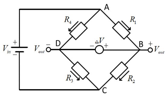
The measurement principle of WOB and torque are basically the same. They mainly measure the system resistance value changes caused by the micro deformation of strain gauges or single-crystal silicon chips with piezoresistive effect through the voltage change collection using a Wheatstone bridge, thereby measuring the corresponding WOB and torque, as shown in Figure 1. The above voltage change measurement is mainly based on the Wheatstone bridge. During the measurement of WOB and torque, four resistors with the same resistance value, R1, R2, R3, and R4, form a Wheatstone bridge.
Figure 1.
The diagram of the Wheatstone bridge circuit.
The voltages at the ends of R2 and R3 are respectively as follows.
The obtained Vout voltage is as follows.
When the strain gauge or single-crystal silicon sheet is not subjected to force, the Wheatstone bridge is in a balanced state and its output voltage is 0; while when the strain gauge or single-crystal silicon sheet undergoes deformation, the resistance values of R1, R2, R3, and R4 will change accordingly, thereby affecting the value of the output voltage Vout. Therefore, the change in pressure is converted into a change in resistance value, and the change in resistance value is converted into the output voltage. When the WOB and torque are different, the output voltage will also be different. The above values can be obtained by measuring the output voltage.
Two sets of strain gauges are used. The set for measuring WOB is arranged at 0° and 90° along the drill tool axis, while the set for measuring torque is arranged at ±45° along the drill tool axis. The measurement bridge adopts a full-bridge configuration. Through a scientific placement method, the coupling between parameters can be effectively reduced. In harsh drilling environments, mechanical deformation causes changes in the resistance of the strain gauges, breaking the Wheatstone bridge balance and outputting a differential voltage. The use of a full-bridge circuit together with temperature-compensated strain gauges cancels out interferences such as temperature and vibration during drilling, thereby accurately converting mechanical deformation into a linear electrical signal.
3.2.2. Rotation Speed Measurement
Rotation speed measurement mainly utilizes MEMS (micro electro mechanical system) gyro for detection. Inside the MEMS gyro, there is a high-frequency vibrating mass. When the drill tool rotates about its axis, the mass is subjected to a Coriolis force proportional to the angular velocity, causing the vibration direction to deflect. The deflection is detected by capacitive or piezoresistive elements and converted into an electrical signal, which directly outputs the real-time angular velocity, i.e., the rotational speed. During the drilling process, anti-vibration filtering, temperature compensation, and dynamic correction algorithms are applied to eliminate interference from drilling dynamic factors on the gyro sensor, achieving continuous and stable measurement of rotational speed.
3.2.3. Vibration Measurement
Vibration measurement mainly utilizes the measurement principle of accelerometers for monitoring. Its working principle is based on the principle of mass inertia and the piezoelectric effect. The sensor contains a small vibrating mass as the acceleration sensitive element, which vibrates along with the object, and the acceleration is proportional to the vibration acceleration of the object. The vibrating mass is usually connected to a piezoelectric material. Under the piezoelectric effect, the strain caused by the vibration generates a charge difference, which in turn produces a voltage signal. The sensor measures the change in voltage signal to indirectly measure the acceleration of the vibrating mass, thereby obtaining the vibration acceleration information of the object. During the drilling process, the acceleration sensor achieves precise and stable vibration measurement by employing mechanical vibration isolation, digital filtering, and temperature compensation to suppress drilling shocks and noise, combined with real-time zero-drift correction.
3.3. Formation Gamma Parameter
Gamma ray is a type of high-energy electromagnetic radiation that can penetrate matter. By measuring the natural gamma ray intensity present in the formation, the content of radioactive elements can be obtained, and then the composition and property of the formation can be inferred. A gamma detector is usually composed of crystals. A dedicated scintillation detector was developed through joint research and development. The detector’s housing and internal circuit do not share a common ground, meeting the explosion-proof and low-power requirements of underground engineering. When gamma rays in the formation pass through the detector, photons are produced, which are captured by the detector and converted into electrical signals. The acquisition circuit amplifies, filters, and corrects the radioactive energy and finally generates an electrical pulse signal.
3.4. Measurement Scheme of Near-Bit Multi-Parameter
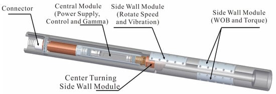
The internal installing space of the small-diameter drill tool at the borehole bottom is limited, making the deployment of multiple sensors difficult. Adopting the conventional approach of placing sensors in the center of the drill tool would bring several problems. First, the inner diameter of the drill tool would need to be enlarged to provide sufficient space for sensor installation, which would significantly reduce the wall thickness and thus the strength of the drill tool, affecting drilling safety. Second, the overall length of the measurement module would increase, placing the measurement point farther from the drill bit and reducing the timeliness of the measurement data. Third, the WOB and torque sensors need to be installed close to the sidewall of the drill tool, a center placement would reduce measurement accuracy. Therefore, an innovative “center + side wall” distributed layout scheme for multiple types of sensors was proposed, as shown in Figure 2. This scheme makes full use of the internal and outer wall space of the drill tool. Sensors such as strain, gyroscope, and acceleration are arranged on the outer wall to collect data on WOB, torque, rotation speed, and vibration. An acceleration sensor is placed at the center to measure the borehole inclination, and a gamma sensor is also installed to identify the rock property. This solution enables the proper installation of multiple sensors within a small-diameter drill tool of 89 mm. Meanwhile, to eliminate the installation errors caused by the distributed layout scheme, precision mechanical positioning and laser calibration are adopted. Combined with multi-position calibration, an error compensation matrix is established. Through a calibration algorithm, the shafting deviation and position misalignment are corrected in real time to ensure measurement accuracy in small-diameter confined spaces.
Figure 2.
Measurement scheme of multiple sensors.
4. Wireless Communication Method of Near-Bit MWD
During near-bit wireless communication, the transmitter sub rotates together with the rotor of the hollow screw tool, imposing high requirements on the anti-interference capability of the wireless communication. At the same time, the near-bit MWD generates a large volume of data, and the construction period for a single borehole in an underground engineering is short, demanding a high wireless communication data rate. Furthermore, the wireless communication module is powered by a battery pack; to reduce the number of trips for battery replacement, the transmission power should be kept as low as possible. Considering the special application requirements of underground operating conditions, data rate, and battery life, and based on a comparison of the characteristics of Bluetooth, EM waves, and acoustic waves, Bluetooth is proposed for wireless transmission across the hollow screw tool, as shown in Table 1. Based on comprehensive consideration of special application scenarios such as the installation size, explosion protection requirement, and data transmission rate in underground and tunnel engineering, it is proposed to use Bluetooth for the wireless transmission of near-bit MWD. Bluetooth is a short-range wireless communication technology that transmits data between devices via radio wave. Its operating frequency ranges from 2.4 to 2.485 GHz, with an emission power of approximately 0.03 W, and the theoretical transmission rate can exceed 1 Mbps [24,25].
Table 1.
Wireless communication methods comparison.
4.1. Characteristics of Wireless Signal Transmission in Water
Since the medium within the Bluetooth transmission channel is water, it is necessary to analyze the transmission characteristics of Bluetooth signal in the water environment, in order to guide the design of the wireless communication scheme across screw drilling tool.
The characteristics of Bluetooth signal propagating in water conform to Maxwell’s equations, and the signal strength attenuation follows an exponential decay law [26]. The attenuation formula of the signal strength with respect to distance is as follows.
The degree of signal attenuation can be calculated using the following formula.
In the formula, S(d) is the signal strength of the Bluetooth transmission reaching point d; S(0) is the signal strength of the Bluetooth transmission; α is the attenuation coefficient of the Bluetooth signal; d is the transmission distance of the Bluetooth signal; L is the attenuation amount of the Bluetooth signal.
The value of the Bluetooth signal attenuation coefficient α depends on the complex dielectric constant of water. Based on Maxwell’s equations, the following formula can be derived.
Formula (11) can be simplified under the condition of high conductivity medium as follows:
In the formula: f is the frequency of the Bluetooth signal; μ is the magnetic permeability of water; σ is the electrical conductivity of water.
Substituting Formula (12) into Formula (9), the Bluetooth signal attenuation model can be obtained as
From Formula (13), the following conclusions can be drawn. In the water environment, the Bluetooth signal shows an exponential rapid attenuation with the increase in transmission distance; in the pure water environment, the attenuation coefficient of the Bluetooth signal is approximately 3.5 to 4.0 Np/m, which is 30 to 35 dB/m; the effective transmission distance does not exceed 0.5 m; in the water containing mineral, the attenuation coefficient of the Bluetooth signal is approximately 9.0 to 11.5 Np/m, which is 80 to 100 dB/m, and the effective transmission distance does not exceed 0.2 m.
The theoretical calculation formula for Bluetooth signal receiving sensitivity is consistent across different media such as air and water; the particularity of underwater applications lies more in the change in the modulation environment [27].
In the formula: −174 dBm is the thermal noise power spectral density; B is the bandwidth, taken as 1 Mbps; NF is the noise figure, typically taken as 7 dBm for low-power Bluetooth; SNRmin is the minimum signal-to-noise ratio, typically taken as 16 dBm in air and 20 dBm in water due to multipath effects. It can be concluded that the Bluetooth receiving sensitivities in air and water are −91 dBm and −87 dBm, respectively.
The Bluetooth signal link margin is the safety margin by which the received signal strength exceeds the sensitivity.
It can be seen from Formula (16) that when Bluetooth transmits over 100 mm in water, the received signal strength is −17.5 dBm and the link margin is 69.5 dB, which can meet the requirements for stable data transmission.
4.2. Wireless Communication Scheme of Near-Bit MWD
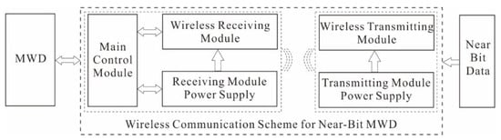
To meet the technical requirements for efficient wireless transmission of near-bit data, based on the analysis of special application scenarios in underground and tunnel engineering, a wireless communication scheme for near-bit MWD in small diameter confined space was designed, as shown in Figure 3.
Figure 3.
Technical proposal of wireless communication technology across screw drilling tool.
This scheme is composed of components such as a wireless transmitting module, a transmitting power supply module, a wireless receiving module, a receiving power supply module and a main control module. The wireless transmitting module is powered by the transmitting power supply module and is used to receive the near-bit data and transmit the data to the wireless receiving module; the wireless receiving module is powered by the receiving power supply module, receives the near-bit data sent by the wireless transmitting module and transmits it to the upper downhole measurement instrument via a wired connection; the wireless transmitting module and the wireless receiving module communicate bidirectionally via Bluetooth; the main control module is used to monitor the working status, and control the transmission and reception of the near-bit data.
4.3. Wireless Communication Simulation Analysis of Near-Bit MWD
All modules of the near-bit MWD wireless communication are arranged within the internal channels of the metal drill tool, and the medium inside the channels is high-pressure water flushing fluid. The metal drill tool has a strong shielding effect on the Bluetooth signal, which can easily form induced eddy currents on the surface of the drill tool and be reflected; at the same time, the high pressure water flushing fluid has a strong polarization absorption effect on the Bluetooth signal, causing rapid attenuation of the Bluetooth signal. However, in actual application conditions, both the metal drill tool and the high-pressure flushing fluid exist simultaneously, and the influence of these factors on the Bluetooth signal is complex and unclear. Therefore, a simulation analysis of Bluetooth wireless communication was conducted to guide the development of near-bit MWD wireless communication technology.
4.3.1. Simulation Model Construction
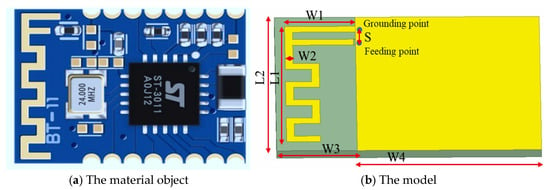
The Bluetooth wireless communication antenna consists of three parts: an inverted F-shaped folded antenna, a dielectric layer, and a ground plane, as shown in Figure 4. The material of the dielectric layer is glass fiber epoxy resin, which is the most commonly used in PCBs (Printed Circuit Board). Its loss tangent is 0.02. The thickness of the dielectric layer is 0.8 mm.
Figure 4.
Antenna circuit of Bluetooth wireless communication.
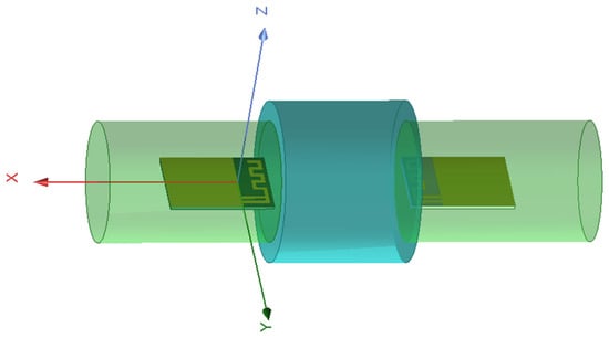
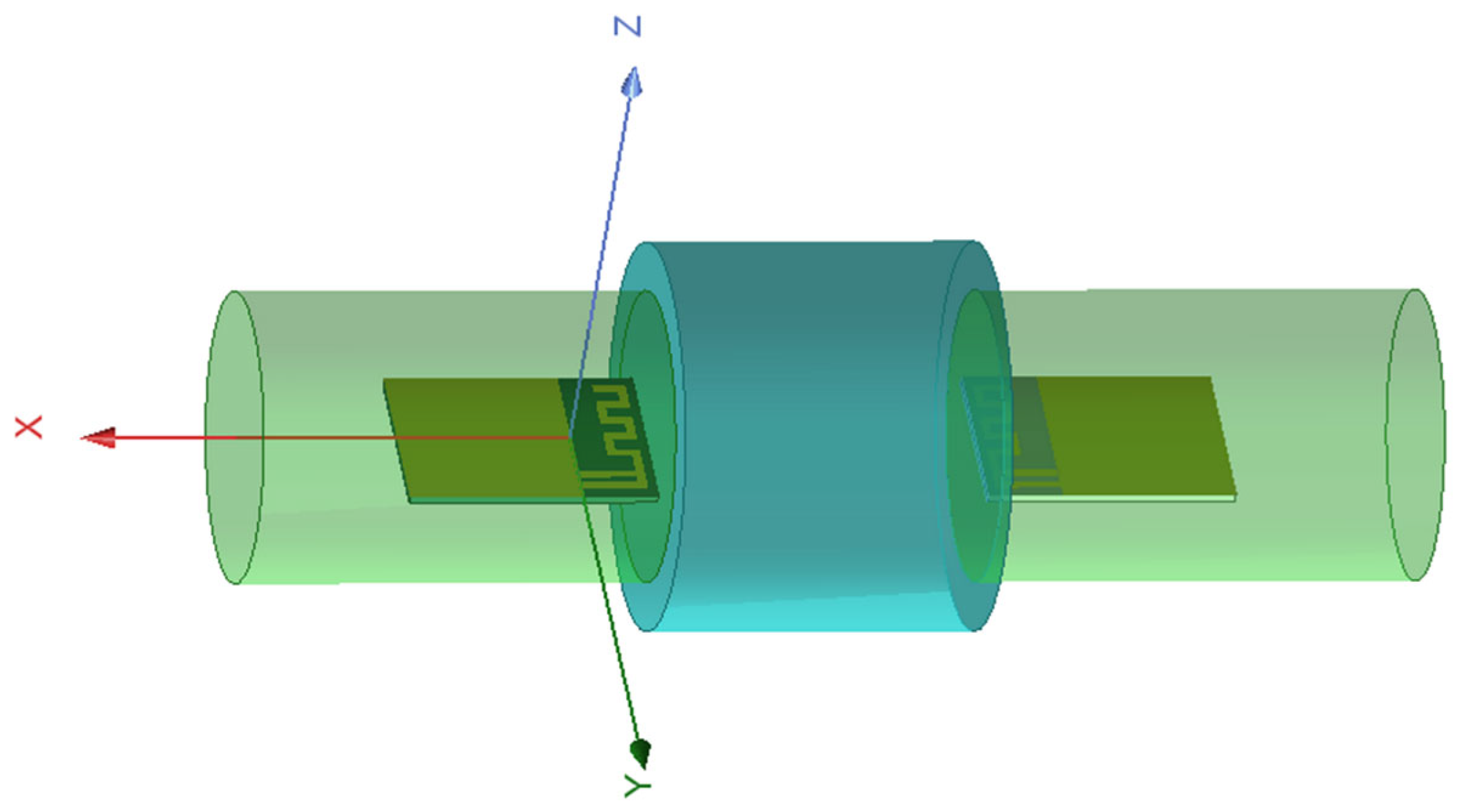
In ANSYS 16.0 EM, the geometric model of the Bluetooth wireless communication antenna is established as shown in Figure 5. The specific model parameters are: the length L2 of the dielectric layer is 100 mm, the width W3 is 40 mm; the length W4 of the ground plane is 120 mm, the width L2 is 100 mm; the horizontal length L1 of the inverted F-shaped folded antenna is 85 mm, the antenna height W1 is 35 mm, the width W2 of the microstrip antenna is 3.0 mm, the distance S between the ground connection point and the feed point is 5.0 mm, and the thickness H of the dielectric layer is 9 mm. The electrical numerical parameters of the simulation model are shown in Table 2. The assumptions of the communication model are as follows: there is no other EM interference during the simulation; the simulation analysis is static, and antenna rotation is not considered.
Figure 5.
Antenna geometric model of Bluetooth wireless communication.
Table 2.
Electrical numerical parameters of the simulation model.
4.3.2. Simulation Result Analysis
- (1)
- Transmission Power
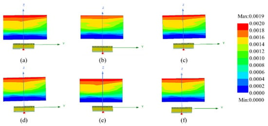
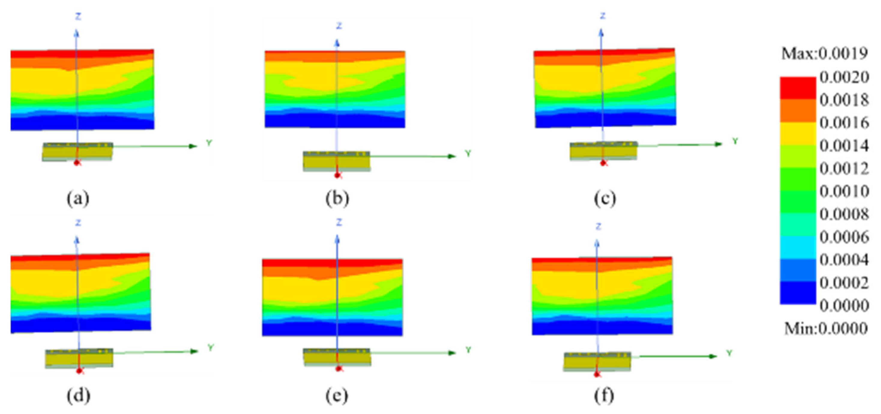
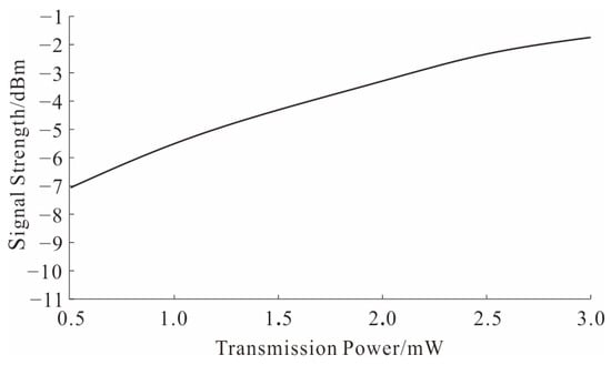
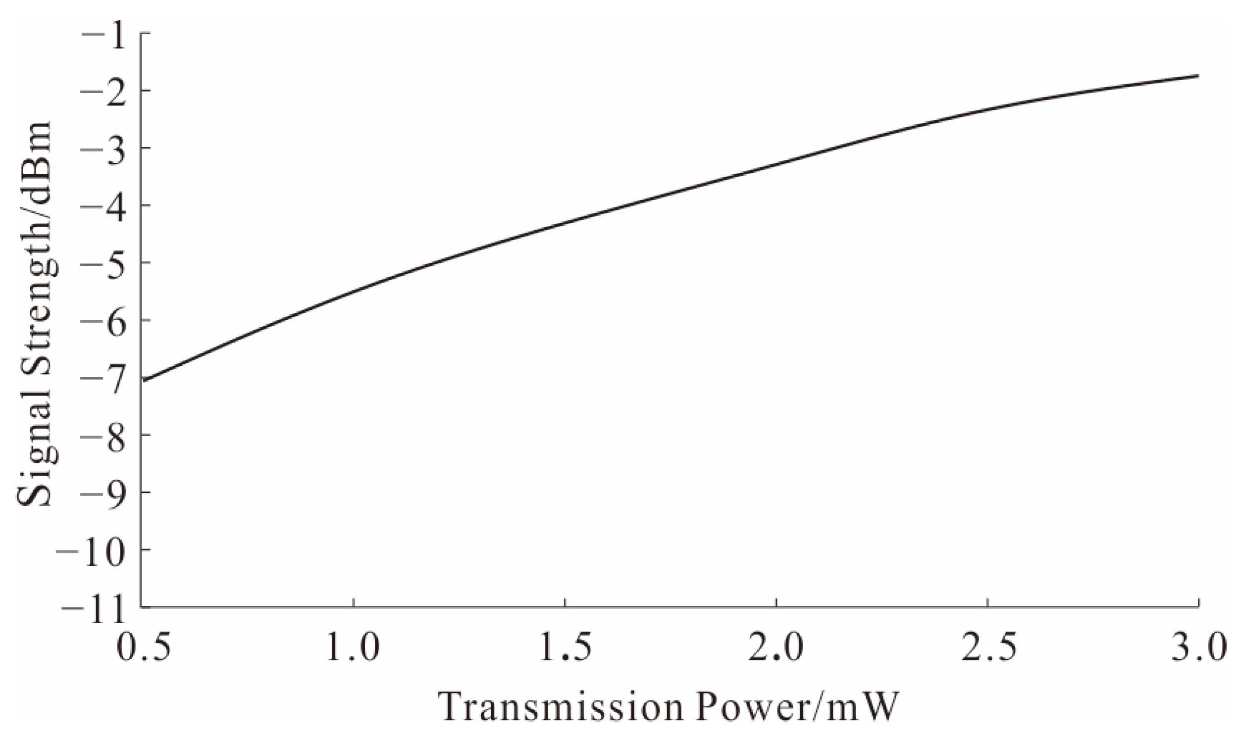
When the transmission power P of the wireless transmitting module changes, the characteristics of the received signal strength by the wireless receiving module are shown in Figure 6 and Figure 7. It can be seen that as the transmission power of the wireless transmitting module increases, the received signal strength changes in an approximately linear trend. The reason is that when the medium and transmission distance are constant, the path loss is a fixed value. The received signal strength equals the transmit power minus this fixed loss. Therefore, the received signal strength increases by exactly the same amount as the transmit power increases. Therefore, appropriately increasing the transmission power can improve the Bluetooth wireless communication effect and extend the communication distance.
Figure 6.
Impact of transmission power on Bluetooth wireless communication. (a) P = 0.5 mW; (b) P = 1.0 mW; (c) P = 1.5 mW; (d) P = 2.0 mW; (e) P = 2.5 mW; (f) P = 3.0 mW.
Figure 7.
Impact of transmission power on received signal strength.
- (2)
- Transmission Medium
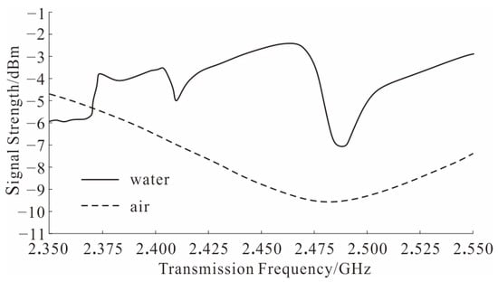
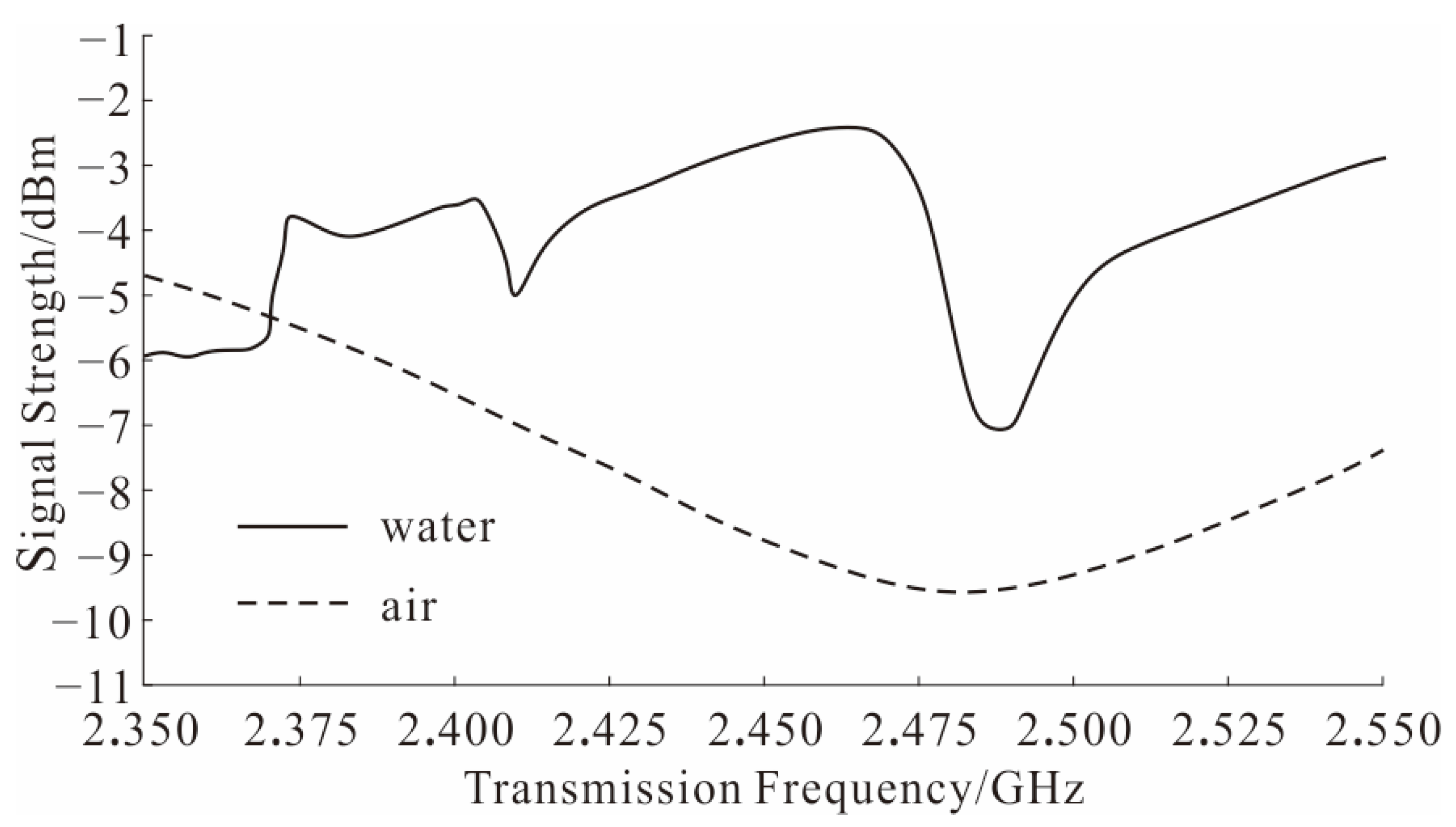
When the transmission medium is water and air, the signal receiving characteristics of the wireless receiving module are shown in Figure 8. It can be seen that when the transmission medium is water, the received signal is unstable, and the echo loss curve shows a fluctuating pattern of highs and lows, demonstrating a frequency shift feature. Oscillation echoes in water arise from the reflection and coherence of EM waves within finite boundaries, forming spatial standing waves. Coupled with severe impedance mismatch caused by extremely short wavelengths and high dielectric constants, which results in energy reflection and fast fading. This causes severe fluctuations of the received signal, burst errors, and spatial instability of the connection, seriously reducing the continuity and reliability of real-time data, and it is a key dynamic factor that must be considered in the model. When the transmission medium is air, the received signal is relatively stable, and the echo loss curve shows a parabolic form; the echo loss of the Bluetooth wireless signal transmitted in water is significantly higher than that transmitted in air, indicating that the Bluetooth signal decays rapidly when transmitted in water. The main reason is that water molecules are strongly polar, and water often contains dissolved ions. When EM waves pass through, the repeated orientation of water molecules generates frictional losses, while ion movement forms conduction currents and eddy currents, rapidly converting energy into heat. In contrast, air has almost no polarity or conductivity, resulting in minimal losses.
Figure 8.
Impact of transmission medium on Bluetooth wireless communication.
- (3)
- Transmission Distance
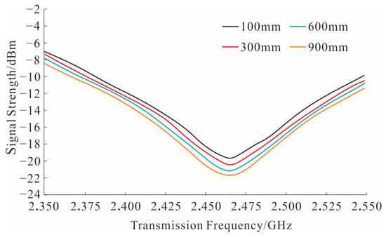
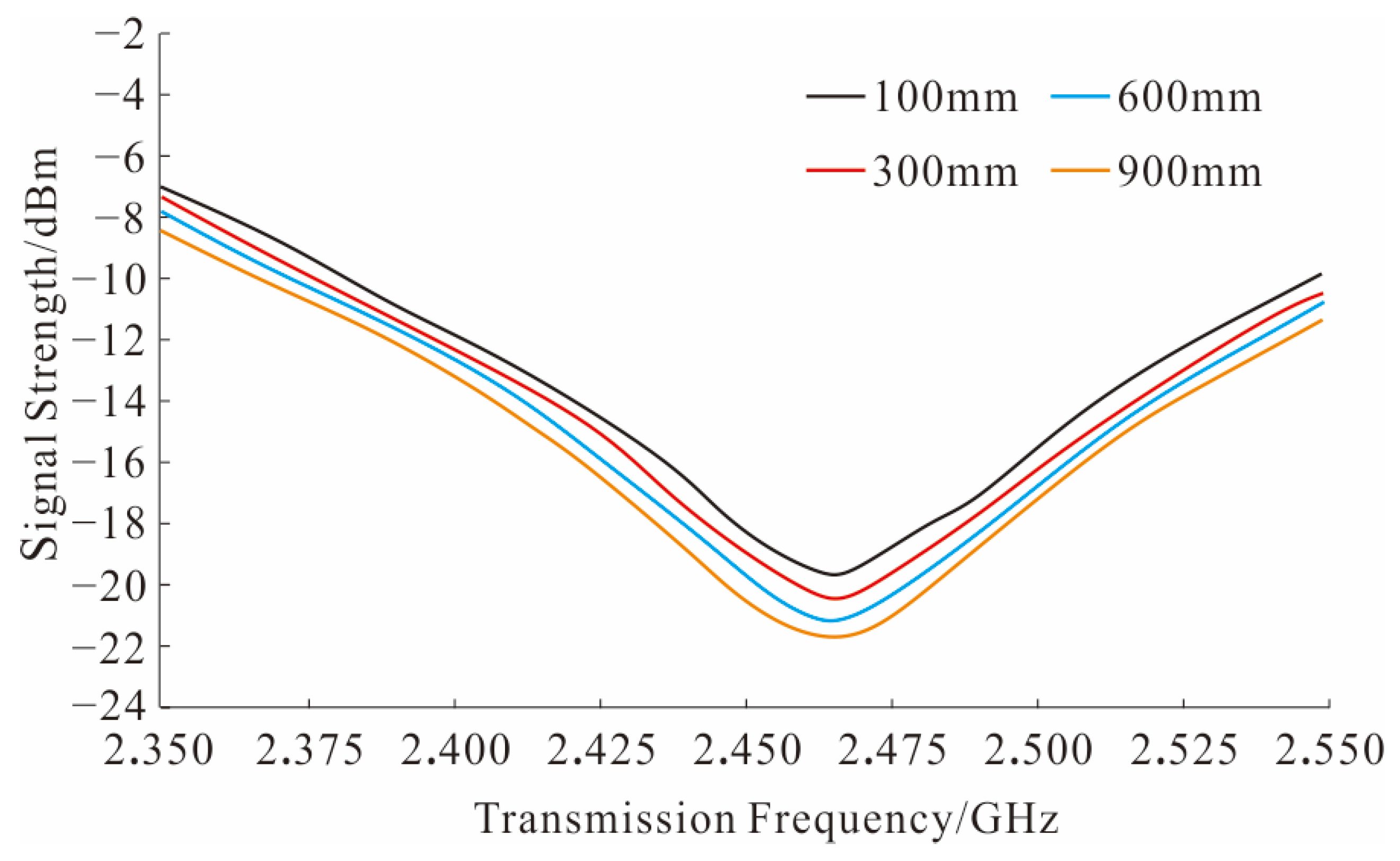
When the transmission medium is water and the transmission distance between the wireless transmitting module and the wireless receiving module changes, the signal strength characteristics received by the wireless receiving module are shown in Figure 9. It can be seen that when the transmission distance increases near the optimal transmission frequency of 2.4 GHz, the return loss increases, and the signal strength received by the wireless receiving module gradually decreases. Therefore, the transmission distance should be appropriately reduced to improve the Bluetooth wireless communication effect.
Figure 9.
Impact of transmission distance on Bluetooth wireless communication.
From the above simulation results, it can be seen that in order to ensure the wireless communication effect of Bluetooth in the complex environment of metal drill tool and high pressure flushing fluid, the transmission power can be set at 1 mW, which will increase the effective battery-powered operating time, under the condition of short-range wireless communication within 1 m; the optimal transmission frequency should be set around 2.4 GHz; at the same time, according to the theoretical analysis results of the link margin, the distance between the wireless transmitting module and the wireless receiving module should be appropriately reduced, so the transmission distance is set at 100 mm.
4.3.3. Theoretical Analysis Verification
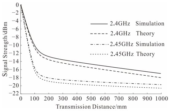
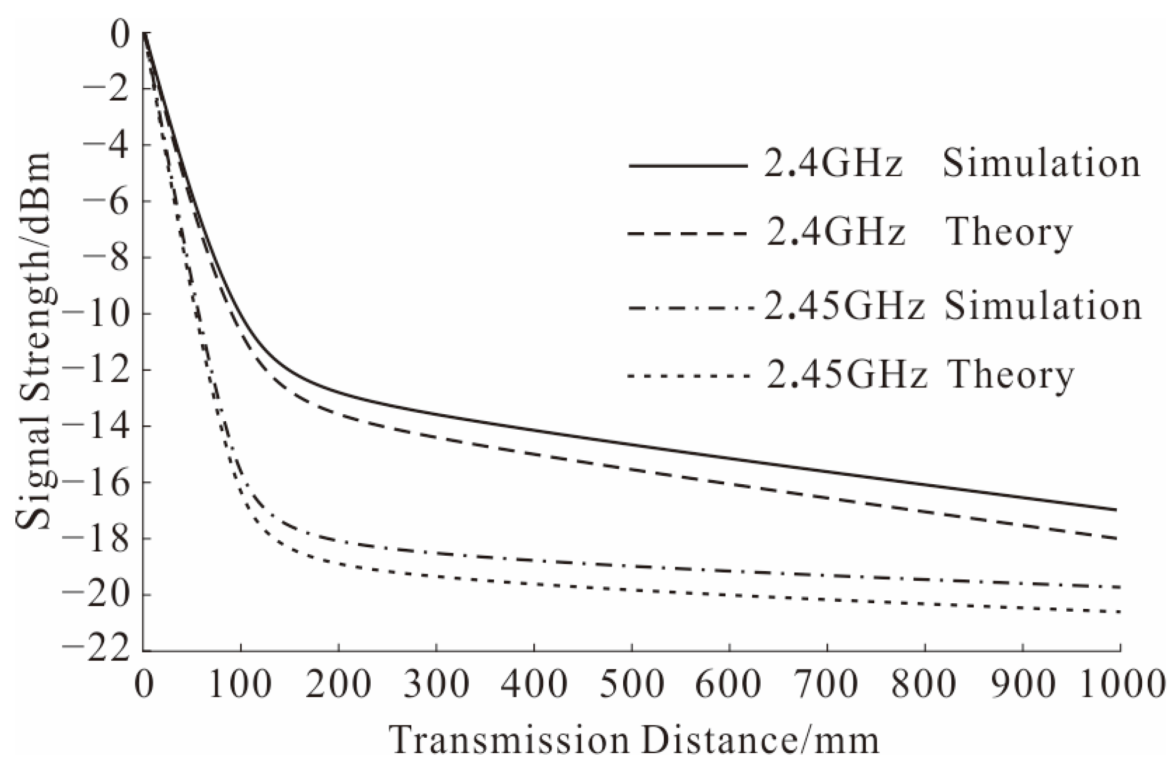
Under the condition of using water as the transmission medium, a comparative analysis was conducted between the theoretical analysis and simulation results of Bluetooth signal transmission characteristics, as shown in Figure 10. At the same signal frequency, both theoretical and simulation results indicate that the signal strength decays rapidly with increasing transmission distance, exhibiting the same trend and similar attenuation levels. When the frequency increases from 2.4 GHz to 2.45 GHz, both theoretical and simulation results show further attenuation of the signal strength. The simulation results are in good agreement with the theoretical analysis, verifying the feasibility of the theoretical analysis.
Figure 10.
Comparison of theoretical analysis and simulation.
5. Device Development of Near-Bit Multi-Parameter MWD
5.1. Overall Design
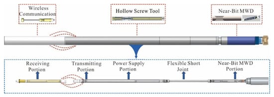
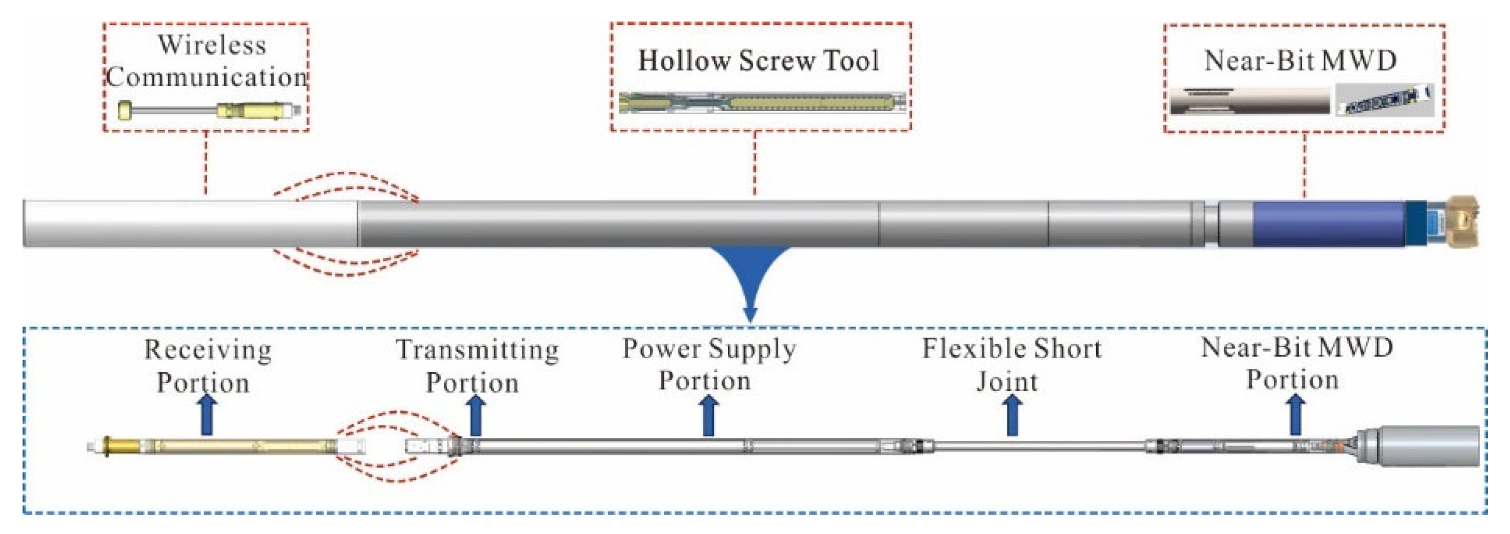
Based on the completion of the overall scheme design, research on multi-parameter MWD method and wireless communication technology was carried out, and the near-bit multi-parameter MWD device was developed. The structural composition is shown in Figure 11.
Figure 11.
Device composition of near-bit multi-parameter MWD device.
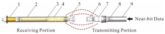
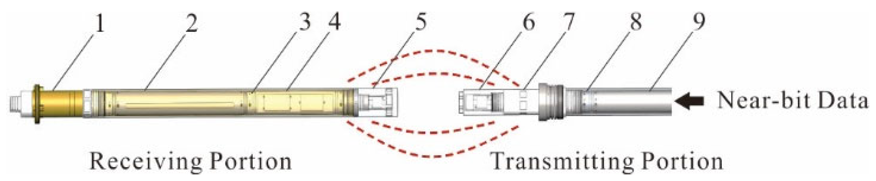
The wireless communication part of the device includes the transmitting circuit board, transmitting battery tube, transmitting circuit board support, transmitting non-metallic plug, receiving circuit board, receiving end battery tube, receiving circuit board support, receiving non-metallic plug, and cable connector, as shown in Figure 12. Both the wireless communication transmitter and receiver are powered by rechargeable lithium iron phosphate battery packs. The output voltage and current are limited to 7.2 V and 3.23 A, respectively. The total capacitance and inductance of the electrical components are 9.2 μF and 48.7 μH, respectively. The system is intrinsically safe and meets the explosion-proof requirements for underground engineering.
Figure 12.
Device composition of wireless communication part. 1. Cable connector, 2. Receiving battery tube, 3. Receiving circuit board support, 4. Receiving circuit board, 5. Receiving non-metallic plug, 6. Transmitting non-metallic plug, 7. Transmitting circuit board support, 8. Transmitting circuit board, 9. Transmitting battery tube.
5.2. Circuit Design
The near-bit MWD circuit uses multiple sensors such as accelerometer, gyroscope, strain gauge, and gamma detector to collect various types of parameters including borehole inclination, WOB, torque, rotation speed, vibration, and gamma in a time-sharing manner. After the parameter collection is completed, the wireless communication circuit transmits the signal. The wireless communication circuit consists of two parts. One part is the automatic transmission and reception circuit centered on the MAX3485 chip, which controls the on-off state of the BC856C transistor through the level of the TX terminal, thereby controlling the transmission and reception direction of the 485; the other part is the CC1310 core chip circuit with a frequency of 2.4 G. The CC1310 core chip communicates with the MAX3485 chip through TTL (Transistor Transistor Logic) signals, and sends instructions through the 485 serial port, thereby enabling wireless transmission of signals between the transmitting circuit board and the receiving circuit board through the CC1310 core chip. The MAX3485 features industrial-grade differential communication characteristics, ensuring stable data transmission from the signal source to the wireless gateway. In addition, both the MAX3485 and the Bluetooth module operate at a supply voltage of 3.3 V, enabling single-power-supply operation and simplifying circuit design. To reduce the interference of water-induced oscillation echoes on real-time data, a small-size ceramic loop antenna is preferred. The signal radiation of this antenna is driven by an alternating magnetic field, which reduces the impact of water on the signal. Meanwhile, impedance matching and antenna tuning are performed based on the signal return loss curve obtained from simulation analysis to compensate for signal absorption by the water medium.
5.3. Program Development
The control instructions for the wireless communication lower-level program of the near-bit MWD mainly include power supply, data acquisition, and data transmission. The terminal at the hole opening sends an on-power command to the receiving circuit board, and after the receiving circuit board is powered on, it sends an on-power command to the sending circuit board; after the sending circuit board is powered on, it controls the near-bit MWD to power on and start continuous data acquisition, and the sending circuit board receives the near-bit data and transmits it wirelessly via Bluetooth to the receiving circuit board; the receiving circuit board receives and uses the wired channel formed by the central communication cable drill pipe to transmit the data in a carrier mode to the hole opening terminal.
5.4. Indoor Test
The physical part of the near-bit MWD device is shown in Figure 13. It is responsible for multi-parameter measurement and data transmission.
Figure 13.
Physical object of near-bit MWD device. The red dotted line represents the illustration of wireless communication.
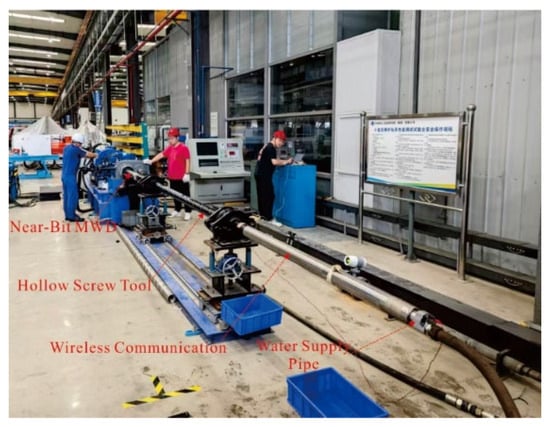
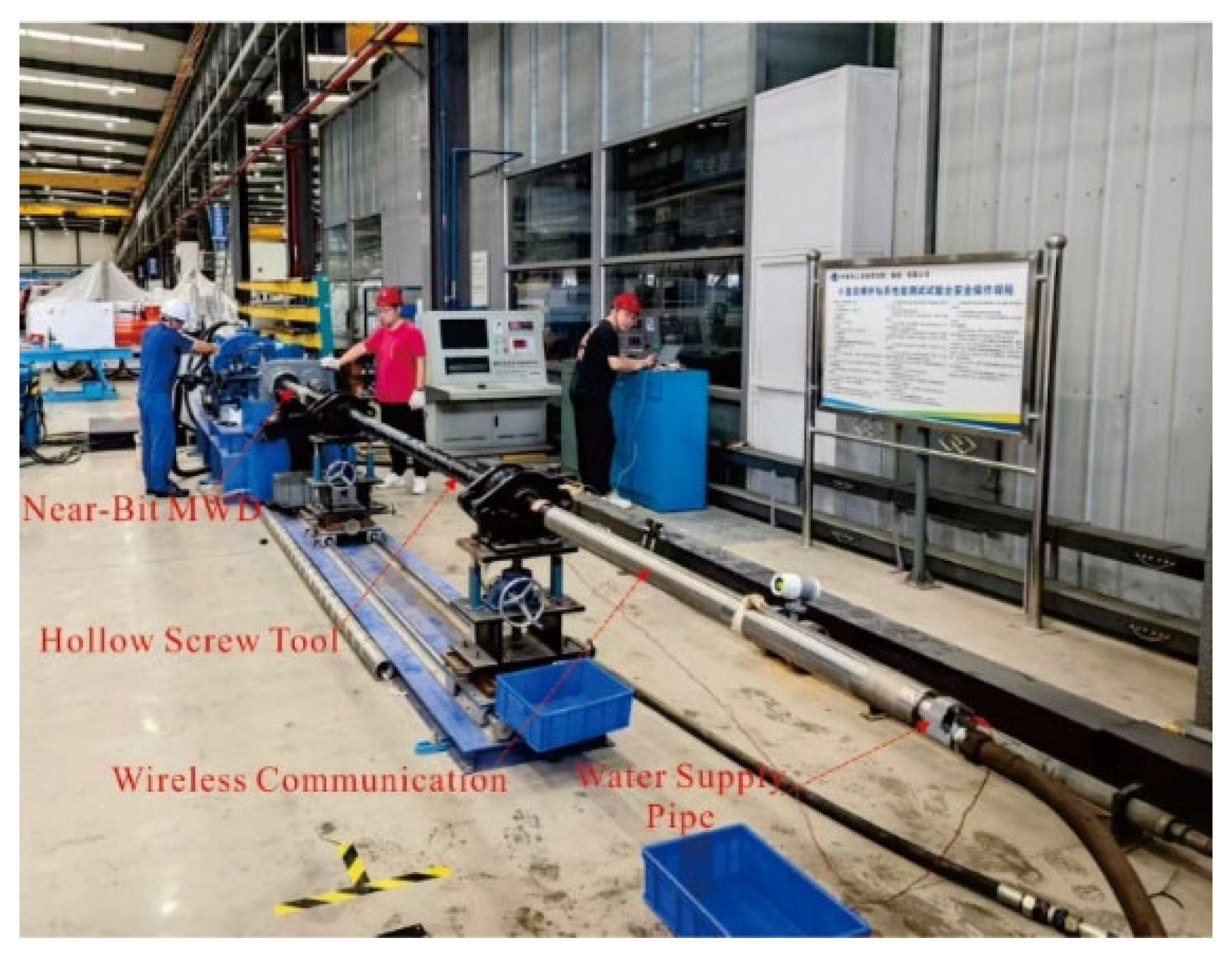
The affiliated unit independently built a screw drill test bench and conducted indoor water flow test, as shown in Figure 14. The near-bit MWD was installed entirely inside the metal drill pipe, with the transmission medium of high-pressure water. The flow rates of the flushing liquid were set at 150, 200, 250, and 300 L/min, respectively. Under the condition of 300 L/min, through the throttling method at the outlet, the maximum water supply pressure reached 10 MPa. The parameter measurement, power supply, and wireless transmission of the near-bit MWD were all normal, and the data reading from the near-bit was stable and continuous. This preliminary verified the performance of the near-bit MWD.
Figure 14.
Indoor test of near-bit MWD device.
5.5. Indoor Test Discussion
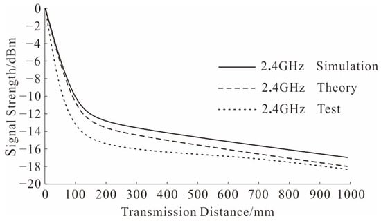
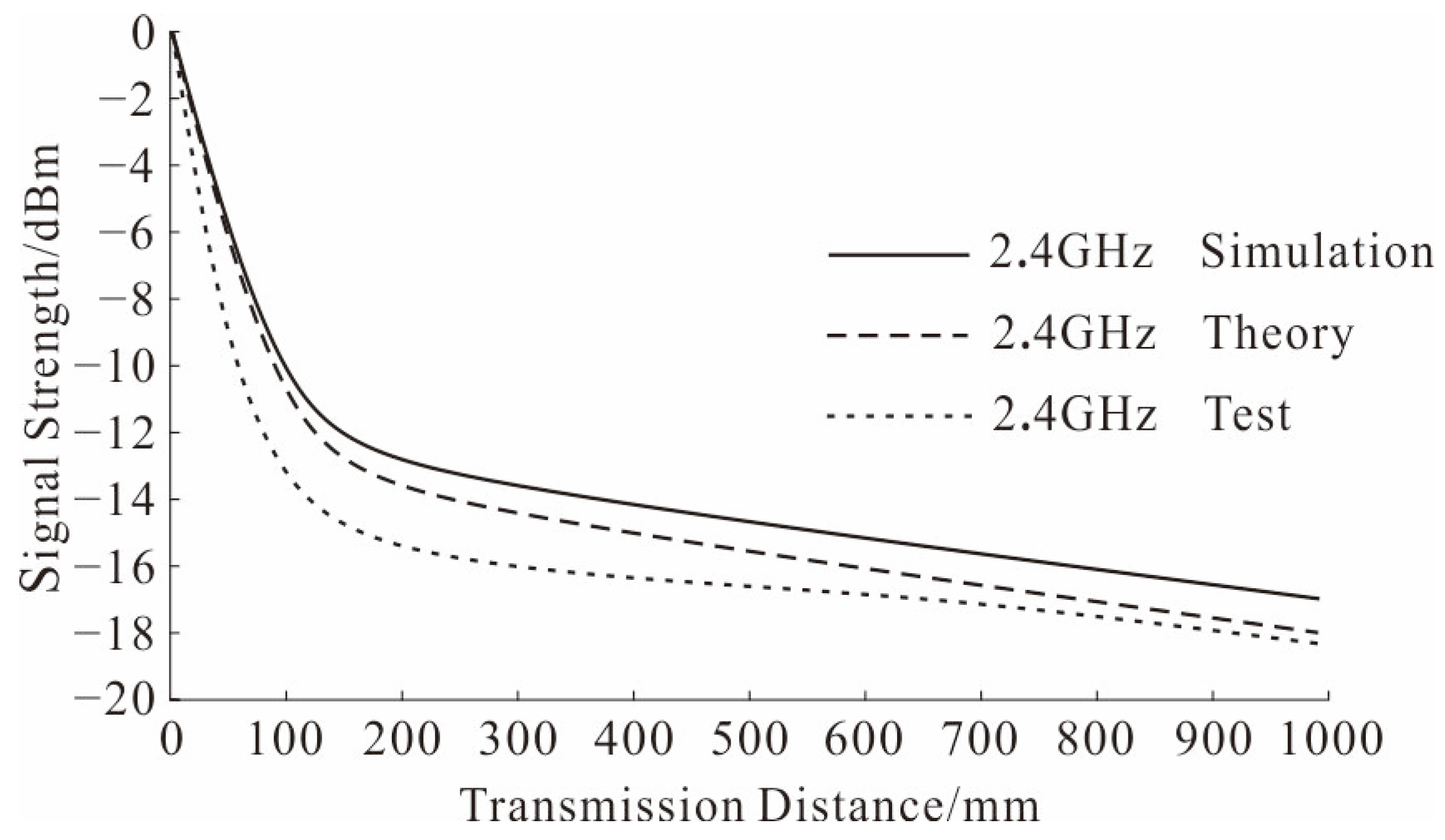
The indoor test results of the Bluetooth signal are shown in Figure 15. Under the conditions of water as the transmission medium and a signal frequency of 2.4 GHz, the signal strength decays rapidly with increasing transmission distance. In the transmission distance range of 0–100 mm, the signal attenuates faster than the theoretical analysis and simulation results. The reason is that the indoor test medium is flowing water, and the unstable flow interface accelerates signal attenuation. In the transmission distance range of 100–1000 mm, the attenuation trend is consistent with the simulation and theoretical analysis trends, verifying the rationality of the theoretical analysis and simulation.
Figure 15.
Indoor test results of signal strength.
The reason why the Bluetooth wireless module operates stably under highly attenuated water environment conditions is as follows: under short-distance wireless communication of 100 mm, the communication mode changes from primarily far-field radiation to a combination of far-field radiation and near-field magnetic induction communication, resulting in improved radiation efficiency and greatly reduced path loss; the pressure-resistant housing of the wireless module is made of non-metallic material, so the penetration loss is low, reducing additional signal attenuation caused by the module itself; the Bluetooth wireless module adopts a small-size ceramic loop antenna, which offers higher radiation efficiency and better directional directivity compared with ordinary PCB antennas.
5.6. Research Innovation Discussion
A comparison between this study and existing near-bit MWD is shown in Table 3. It can be seen that under the same measurement parameters, the near-bit MWD system developed in this study has a smaller size and is applicable to a wider range of scenarios. Meanwhile, the wireless communication rate is significantly improved, meeting the technical requirements for efficient transmission of large data volumes. It should be noted that this study mainly focuses on measurement and communication technologies; multi-parameter fusion analysis and utilization have not yet been carried out. Therefore, it is necessary to make full use of existing near-bit MWD data analysis methods for post-processing of the data.
Table 3.
Comparison with the existing near-bit MWD.
The innovations of this study are reflected in the following aspects: As shown in Figure 9, an innovative overall layout scheme based on a hollow screw tool is proposed, which fully utilizes the internal space to arrange multiple functional modules, solving the problem of module arrangement in confined spaces. As shown in Figure 2, a distributed measurement method of ‘center + sidewall’ is proposed, overcoming the installation constraints of multiple sensors in a small diameter of 89 mm. As shown in Figure 10, on the basis of using the hollow screw tool to move the transmitter module forward to the bit, a Bluetooth-based wireless communication scheme is proposed, achieving high-speed and stable short-distance data transmission of 100 mm in water.
6. Real Drilling Test of Near-Bit MWD
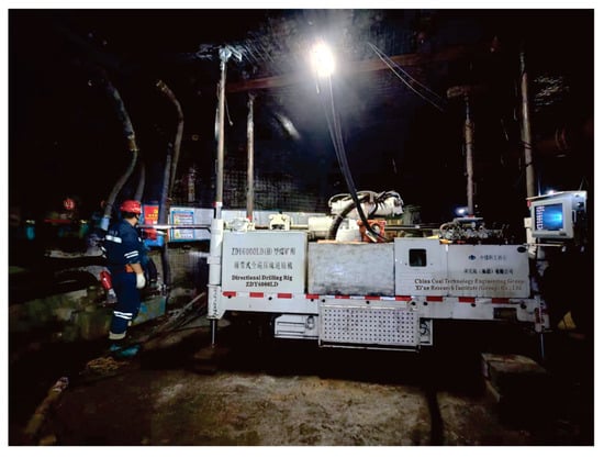
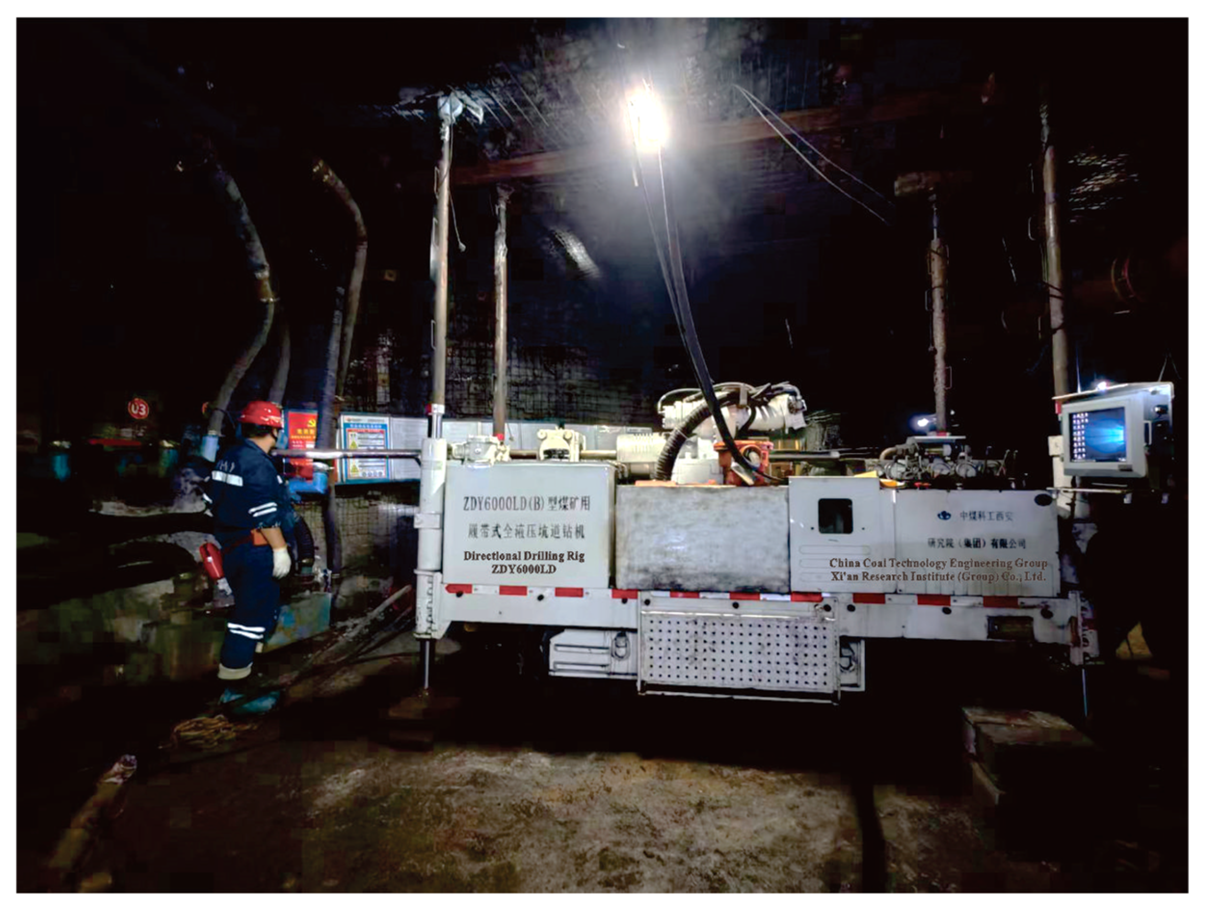
Based on the completion of the near-bit MWD indoor performance test, a real drilling test was carried out in the underground engineering of a coal mine in Wuhai City. The test site is shown in Figure 16.
Figure 16.
Test site of the actual drilling.
6.1. Supporting Equipment
The supporting equipment for the actual drilling test mainly include a directional drilling rig, a mud pump truck, a near-bit MWD module, a transmission screw drilling tool, and a near-bit MWD communication device, etc. The list of supporting equipment is shown in Table 4.
Table 4.
Equipment for actual drilling operation.
6.2. Test Plan
6.2.1. Assembly and Connection of Test Equipment
- (1)
- Assembly of Near-Bit MWD Instrument
First, connect the gamma measurement section, flexible section, and power supply section of the near-bit MWD instrument. After assembly, insert it into the hollow structure from the rear of the hydraulic transmission logging tool until it is extended from the front end of the hydraulic hollow logging tool and connected to the near-bit MWD section. This completes the assembly of the motor end of the near-bit MWD instrument.
- (2)
- Assembly of Near-Bit MWD Communication Device
Assemble the wireless transmitting module, transmitting power supply module, wireless receiving module, receiving power supply module, and main control circuit, and install the near-bit MWD wireless communication device through the fixing ring in the non-magnetic outer tube. The installation position is between the near-bit MWD instrument and the MWD instrument.
- (3)
- Overall Drilling Instrument Connection
Starting from the MWD instrument, connect the central cable drill pipe, water supply device, water supply pipeline, and mud pump truck successively to complete the connection of the test equipment.
6.2.2. Test Procedures
- (1)
- Equipment Debugging
After completing the connection of the test equipment, test the parameter measurement and wireless communication to ensure it is functioning properly before starting to supply water to the equipment; after the water supply pipeline is connected, start the mud pump truck and let it run for a certain period of time to test the connection of the water supply pipeline.
- (2)
- Pipeline Water Supply
Start the mud pump truck and, after the oil temperature reaches the required level, hydraulic oil is used to drive the mud pump, which draws in water, pressurizes it, and delivers it into the pipeline.
- (3)
- Near-Bit MWD Test
After confirming that the hydraulic measurement and transmission drill tool is working properly, collect the display terminal at the hole opening to read the working status of the near-bit MWD instrument and test the near-bit wireless communication.
- (4)
- Real-Drilling Test of Near-Bit MWD
After completing the water supply test of near-bit MWD at the hole opening, connect the central communication cable drill rod and lower it into the test hole for real drilling. During the drilling process, measure the near-bit parameters in real time and test the stability of the near-bit parameter measurement and wireless communication during drilling process.
6.3. Test Results
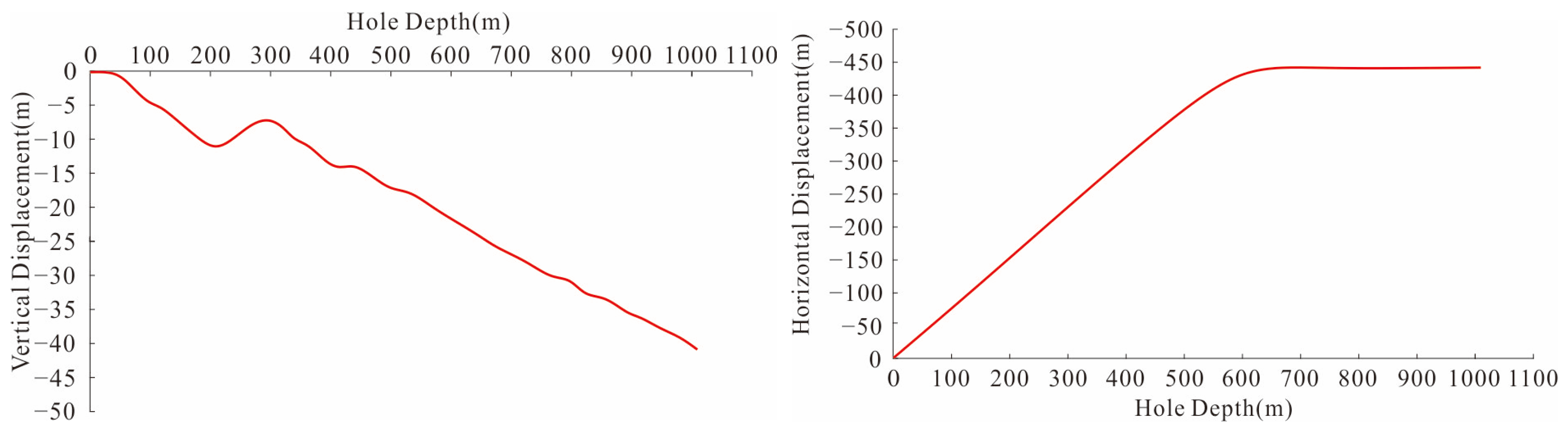
The near-bit multi-parameter MWD device was applied to complete the construction of three test holes. The total test drilling length was 2328 m. The main encountered formation was coal and coal gangue. The borehole trajectory with the greatest depth is shown in Figure 17.
Figure 17.
The trajectory of test drilling boreholes.
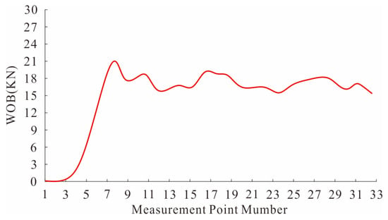
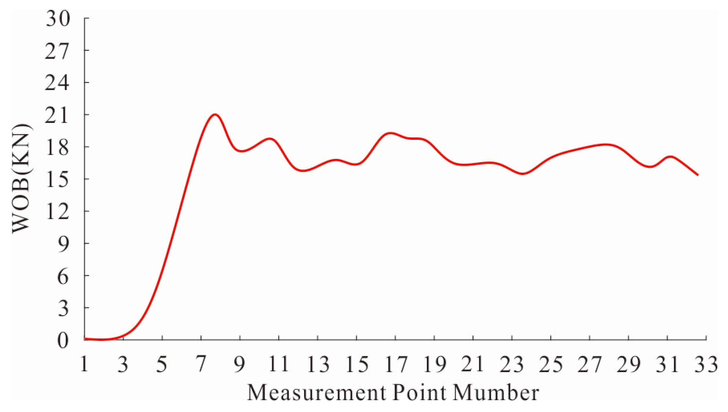
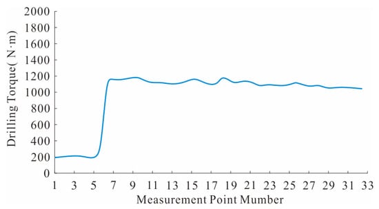
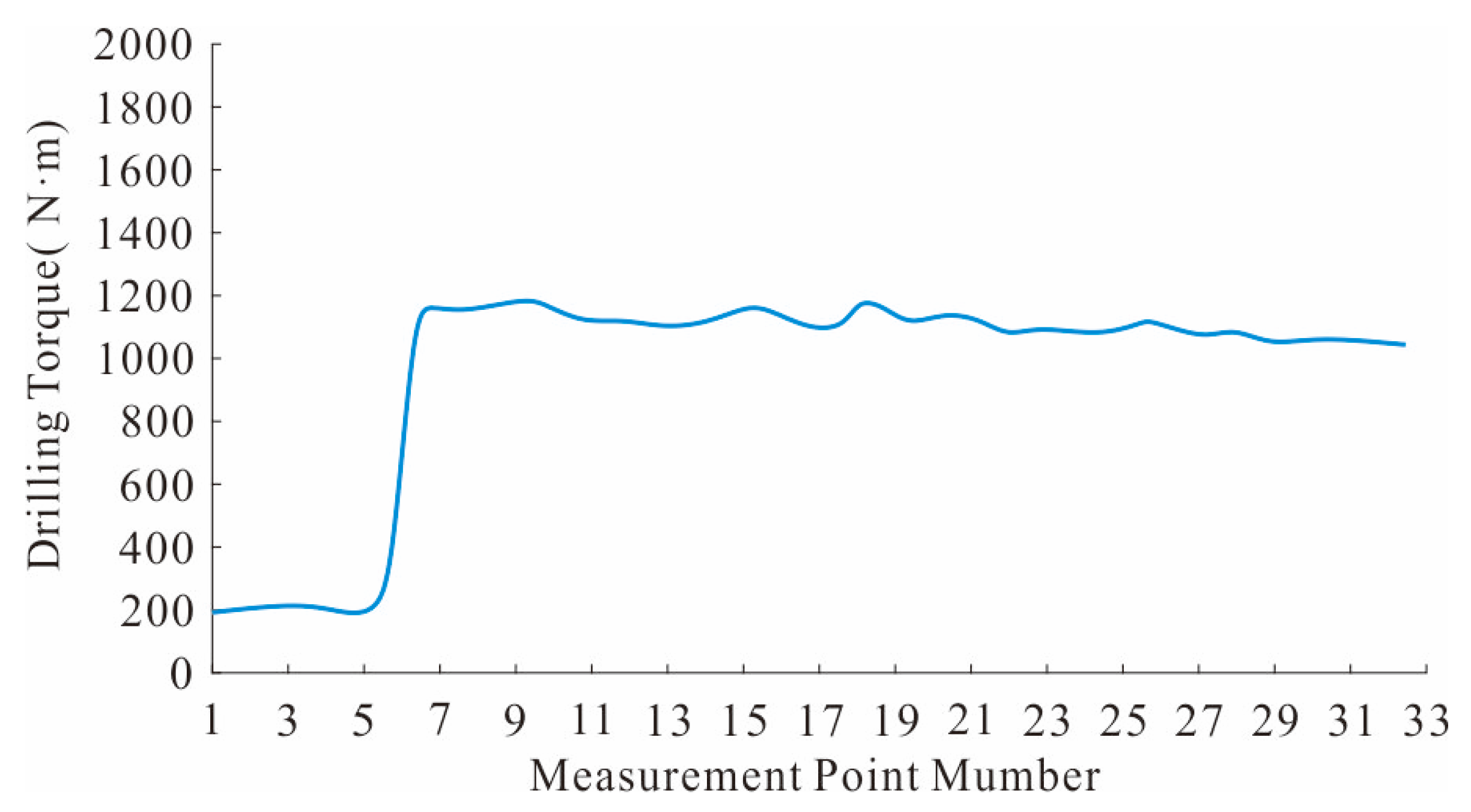
During the test, the near-bit MWD experienced eight packet losses, with a maximum of six consecutive lost frames. The total packet loss rate is approximately 1.4%. No complete signal interruption or permanent link failure occurred. This provided a wireless channel for the data of the near-bit MWD to be transmitted across the screw drilling tool. Various types of data such as WOB, torque, rotation speed, vibration, and gamma were obtained, as shown in Figure 15, Figure 16, Figure 17, Figure 18 and Figure 19. At the same time, a two-way wireless signal channel was provided for the near-bit MWD and the MWD, enabling the communication and exchange of data between them.
Figure 18.
Data of near-bit WOB.
Figure 19.
Data of near-bit torque.
6.4. Test Data Analysis
6.4.1. WOB
As shown in Figure 18 of the measurement results for the WOB, before the drilling construction began, the near-bit WOB was zero; when the drilling rig started to advance and implement sliding directional drilling, the near-bit WOB rapidly increased; during the sliding drilling process, the near-bit WOB remained basically stable at around 15–20 kN.
6.4.2. Torque
As shown in Figure 19 of the measurement results of the torque, before the drilling construction began, water was supplied to the screw drilling tool to start its rotation. At this time, the screw drilling tool was in a no-load state, and the torque near the drill bit was around 200 N·m. When the drilling rig started to advance and implement sliding directional drilling, the torque near the drill bit rapidly increased. During the sliding drilling process, the torque near the drill bit remained basically stable at around 1200 N·m, with a relatively small fluctuation range.
6.4.3. Rotation Speed
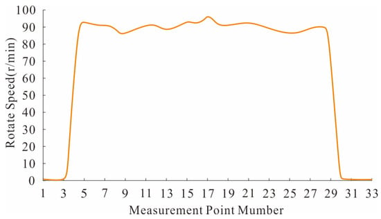
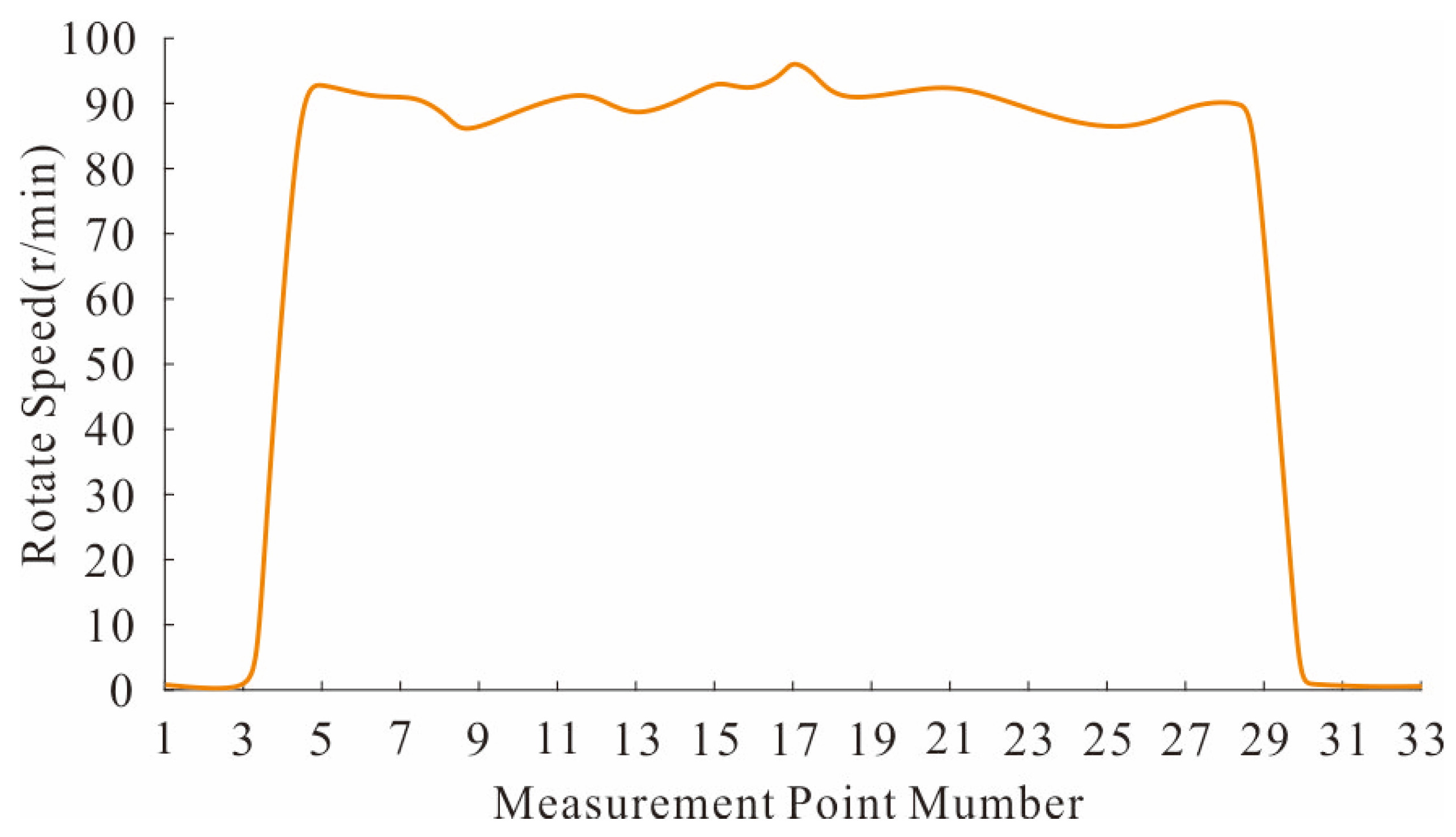
As shown in Figure 20 of the measurement results of the rotation speed, before the drilling operation began, the water screw drilling tool started to rotate in the hole. The rotation speed near the drill bit increased rapidly. When the drilling rig began to advance and implement sliding drilling, the rotational speed near the drill bit remained basically stable at around 90 r/min, with a relatively small fluctuation range.
Figure 20.
Data of near-bit rotation speed.
6.4.4. Vibration
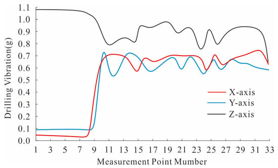
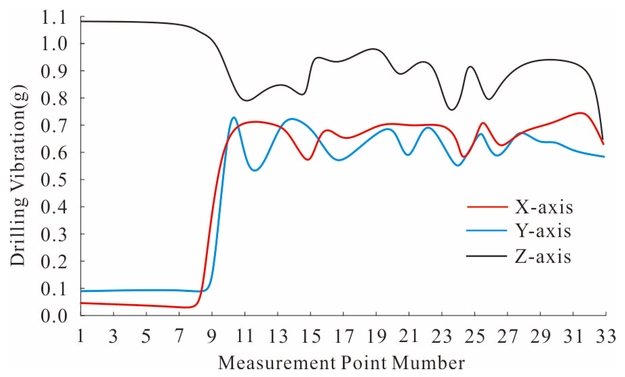
As shown in Figure 21 of the measurement results of the vibration, during the idle rotation, the vibration along the Z-axis was relatively high. However, during the drilling process, the vibration along the Z-axis decreased somewhat. The vibrations along the X and Y axes increase rapidly after the drilling starts and then remain at around 0.7 g. This was because during idle rotation, the drill bit was initially lifted off the bottom of the hole and was in a free state at one end, resulting in relatively large vibrations. After the drilling started, the drill bit pressed against the bottom of the hole, and the drill bit was no longer in a free state, so the vibration was lower compared to the idle rotation.
Figure 21.
Data of near-bit vibration.
6.4.5. Gamma
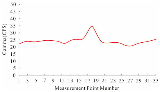
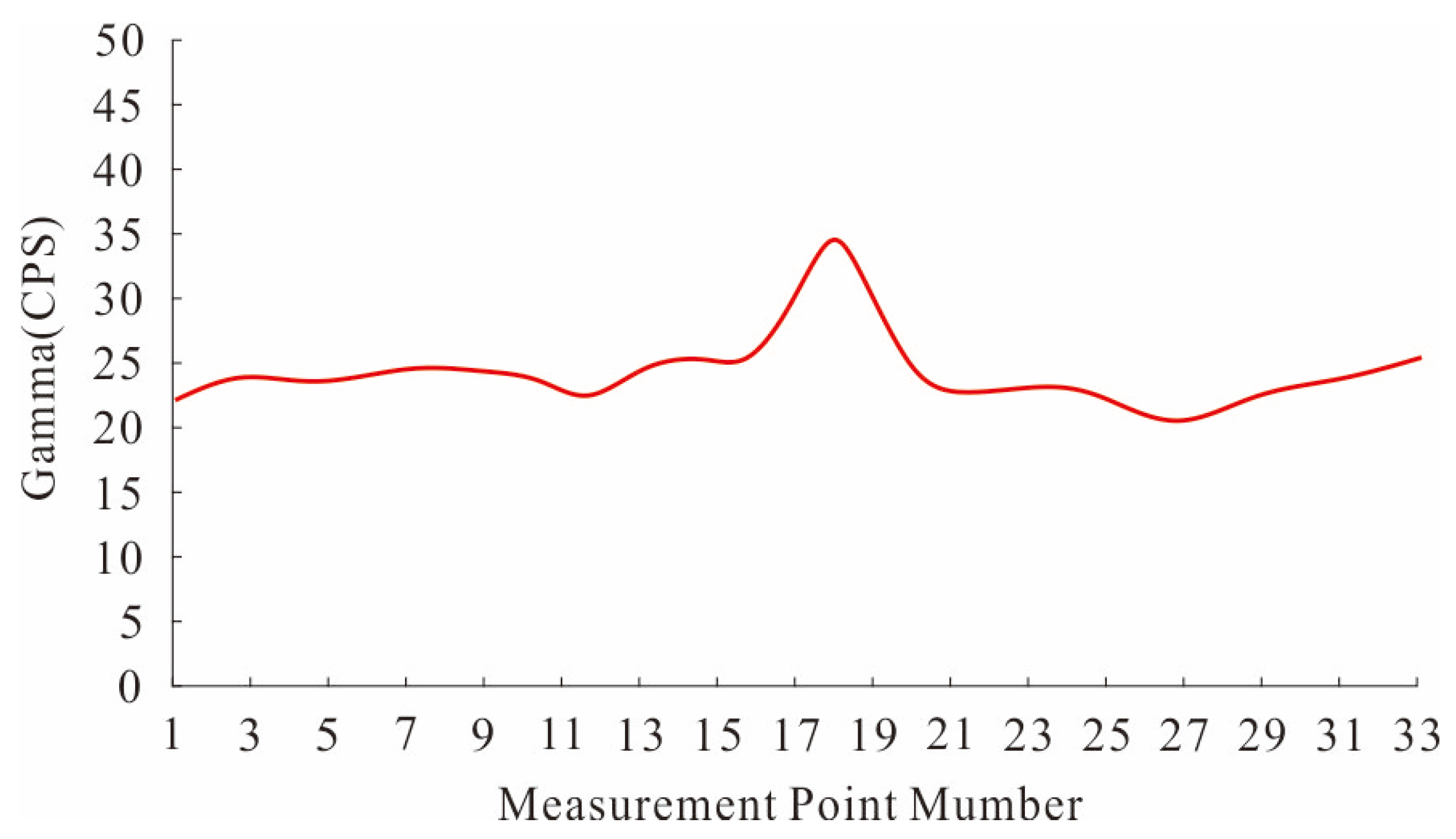
As shown in Figure 22 of the measurement results of the gamma, due to the fact that the borehole extended within the coal and coal gangue, the rock property did not undergo significant change. The overall gamma value fluctuated minimally, generally remaining around 20 CPS. When encountering coal gangue, the gamma value will slightly increase, with the maximum increase being around 10 CPS. Since the natural radionuclide content in coal gangue is generally higher than that in coal, it can be used to assist in identifying coal and coal gangue. The changes could be clearly observed through the return water at the borehole outlet. The actual drilling results were basically consistent with the gamma value test results.
Figure 22.
Data of near-bit gamma.
6.5. System Reliability Discussion Section
In terms of parameter accuracy, based on the distributed measurement layout, each parameter is independently measured by different types of sensors without mutual interference. Taking WOB and torque measurement as an example, a temperature compensation algorithm is used to eliminate temperature drift occurring during long-term use. In terms of wireless communication stability, theoretical analysis, simulation, and experimental tests have all verified the suitability of Bluetooth for short-distance wireless communication in water. Furthermore, by selecting a small-size ceramic loop antenna and optimizing impedance matching and antenna tuning, the radiation capability of the Bluetooth signal has been improved. In terms of structural reliability, the pressure-resistant housing for electronic components is made of high-strength stainless steel, which is widely used in high-end equipment fields, such as petroleum and aerospace. It ensures high water pressure resistance while withstanding the complex loading environment caused by non-coaxial motion inside the positive displacement motor, thus guaranteeing the structural life of the system. In terms of maintenance convenience, a modular design is adopted, facilitating the replacement of power supply module and vulnerable parts during long-term use.
7. Conclusions
To address the technical requirements for precise and efficient borehole trajectory control in underground and tunnel engineering directional drilling, a ‘center + sidewall’ distributed measurement method is proposed. By arranging strain gauges, gyroscope, and accelerometer sensors on the sidewall, and arranging accelerometer and gamma sensors in the center, proper installation of multiple sensors within a small-diameter drill tool of 89 mm can be achieved.
Theoretical analysis of Bluetooth wireless communication was carried out. The attenuation of Bluetooth signals in water can reach up to 80 to 100 dB/m, and the theoretical transmission distance does not exceed 1 m. The receiving sensitivity of Bluetooth in water is approximately −87 dBm. When the transmitting distance is 100 mm, the received signal strength is −17.5 dBm, and the link margin is 69.5 dB.
A wireless communication simulation model for the screw tool was constructed to analyze the influence of transmission power, transmission medium and transmission distance on the Bluetooth signal. Simulation results demonstrate that as the transmit power increases from 0.5 to 3 mW, the received signal strength increases approximately linearly. Considering the battery pack’s endurance, the power is set to 1 mW. When the transmission medium is water, the received is unstable, and the echo loss curve presents a high-low oscillation form; The echo loss of the Bluetooth signal in water is significantly higher than that in air. At the operating frequency of 2.4 GHz, During the process of increasing the transmission distance from 100 mm to 900 mm, the echo loss increases with transmission distance, resulting in a gradually decreasing received signal strength. Considering the multipath effect of Bluetooth transmission in water, the transmission distance is set to 100 mm.
Based on the completion of research on the multi-parameter MWD method and the transmission characteristics of wireless communication, a near-bit multi-parameter MWD device was developed. Five parameters at the near-bit position can be measured, all with measurement zero lengths within 1 m, with the minimum being 0.3 m. The indoor water flow test results show that the wireless communication across the positive displacement motor operates normally in terms of power supply, data acquisition, and transmission commands, and the near-bit data is read stably and continuously. The theoretical analysis, simulation, and indoor test results are in good agreement, verifying the rationality of the signal transmission characteristic analysis.
A drilling test was carried out at an underground engineering of a coal mine in Wuhai City. The total drilling length of the test was 2328 m. Bluetooth wireless communication experienced eight packet losses, with a maximum of six consecutive lost frames. The total packet loss rate is approximately 1.4%. No complete signal interruption or permanent link failure occurred. The test successfully established a wireless data transmission channel across the screw drilling tool. Continuous curves of five parameters at the near-bit position, including WOB, torque, rotational speed, vibration, and gamma, were obtained. This work provides critical technical support for the research and development of near-bit MWD technology in underground and tunnel engineering.
Author Contributions
Conceptualization, Z.C. and S.H.; methodology, Z.C. and S.H.; software, Z.C. and Q.L.; validation, F.L. , Z.C., S.H. and L.C.; formal analysis, F.L., Z.C. and Y.W.; investigation, J.F.; resources, D.Y.; data curation, F.L., J.Z.; writing—original draft preparation, Z.C.; writing—review and editing, S.H. and Q.L.; visualization, Z.C., G.C; supervision, F.L. and G.C.; project administration, Y.W.; funding acquisition, L.C. All authors have read and agreed to the published version of the manuscript.
Funding
This research was funded by the National Key Science and Technology Project, grant number 2024ZD170010201, the Key Research and Development Project of Shaanxi Province, grant number 2025CY-YBXM-607, and the National Natural Science Foundation of China—Regional Innovation Development Joint Fund, grant number U25A20269.
Data Availability Statement
The original contributions presented in this study are included in the article. Further inquiries can be directed to the corresponding author.
Conflicts of Interest
All authors were employed by the company China Coal Technology Engineering Group Xi’an Research Institute (Group) Co., Ltd.
Abbreviations
The following abbreviations are used in this manuscript:
| MWD | Measurement While Drilling |
| MEMS | Micro Electro Mechanical System |
| PCB | Printed Circuit Board |
| EM | Electromagnetic |
| TTL | Transistor Transistor Logic |
References
- Wang, Q.; Gao, H.; Jiang, B.; Li, S.; He, M.; Qin, Q. In-situ test and bolt-grouting design evaluation method of underground engineering based on digital drilling. Int. J. Rock Mech. Min. Sci. 2021, 138, 104575. [Google Scholar] [CrossRef] [Scilit]
- Zhao, R.; Shi, S.; Yao, R.; Yang, S. Application of Relationship model for the Measurement While Drilling Data to Predict Rock Uniaxial Compressive Strength for Tunneling. Rock Mech. Rock. Eng. 2024, 57, 7187–7203. [Google Scholar] [CrossRef] [Scilit]
- Wang, J.; Fang, Q.; Huang, J.; Zheng, G. Multiple-branching hierarchical fusion network for tunnel blasting excavation shape prediction using measurement while drilling data. Tunn. Undergr. Space Technol. Inc. Trenchless Technol. Res. 2026, 171, 107479. [Google Scholar] [CrossRef] [Scilit]
- Wang, G.; Fang, Q.; Wei, J.; Li, J.; Zhang, Q.; Wang, Y. A generalization-oriented fusion model for real-time TBM load prediction. Rock Mech. Bull. 2026, 100313. [Google Scholar] [CrossRef] [Scilit]
- Eldert, J.; Funehag, J.; Saiang, D.; Schunnesson, H. Rock support prediction based on measurement while drilling technology. Bull. Eng. Geol. Environ. 2020, 80, 1–17. [Google Scholar] [CrossRef] [Scilit]
- Werner, C.; Angela, D.; Dieter, K.; Thomas, R.; Günter, S.; Erhard, K.; Hanns, W. Review of the “Tunnel Seismic While Drilling” measurements during construction of the Koralm Tunnel at section KAT2. Geomech. Tunn. 2021, 14, 616–625. [Google Scholar]
- Wang, J.; Fang, Q.; Wang, G.; Zheng, G.; Jin, H.; Chen, J. Semi-supervised recognition of tunnel surrounding rock discontinuities using drilling jumbo data. Autom. Constr. 2024, 166, 105623. [Google Scholar] [CrossRef] [Scilit]
- Lu, M.; Li, H.; Wang, H.; He, Y.; Liu, J.; Wang, Y.; Niu, W. Research and Test on the Device of Downhole Near-Bit Temperature and Pressure Measurement While Drilling. Processes 2023, 11, 11082238. [Google Scholar] [CrossRef] [Scilit]
- Wang, L.; Gou, W.; Wang, J.; Zhou, Z. Anti-Vibration Method for the Near-Bit Measurement While Drilling of Pneumatic Down-the-Hole Hammer Drilling. Appl. Sci. 2024, 14, 8565. [Google Scholar] [CrossRef] [Scilit]
- Li, Z.; Pang, Y.; Liu, Y.; Ke, C.; Song, X.; Liang, Z. Design of positive pulse measurement while drilling system for mine rotary valve mud. J. Phys. Conf. Ser. 2024, 2782, 012019. [Google Scholar] [CrossRef] [Scilit]
- Komadja, C.; Westman, E.; Rana, A.; Vitalis, A. A Machine Learning Approach to Lithology Classification in Mining Using Measurement While Drilling and Exploration Data. Min. Metall. Explor. 2025, 42, 1–19. [Google Scholar] [CrossRef] [Scilit]
- Akyildiz, O.; Basarir, H.; Ellefmo, S. The development of a lithology prediction model using measurement while drilling data in a quartzite quarry. Int. J. Min. Reclam. Environ. 2025, 39, 93–109. [Google Scholar] [CrossRef] [Scilit]
- Chen, J.; Peng, L.; Shan, W.; Lang, L. FPGA-based transceiver implementation with circular polarization excitation for microwave transmission measurement while drilling. Int. J. Electron. Commun. 2026, 206, 156173. [Google Scholar] [CrossRef] [Scilit]
- Zhao, A.; Yu, Y.; Wang, B.; Liu, Y.; Liu, J.; Fu, X.; Zheng, W.; Tian, F. Real-Time Intelligent Recognition and Precise Drilling in Strongly Heterogeneous Formations Based on Multi-Parameter Logging While Drilling and Drilling Engineering. Appl. Sci. 2025, 15, 5536. [Google Scholar] [CrossRef] [Scilit]
- Li, M.; Zhang, H.; Zhao, Q.; Li, W.; Song, X.; Ji, Y.; Wang, J. A New Method for Intelligent Prediction of Drilling Overflow and Leakage Based on Multi-Parameter Fusion. Energies 2022, 15, 5988. [Google Scholar] [CrossRef] [Scilit]
- Xu, X.; Meng, Y.; Liu, Y.; Ji, Y. A study on weight-on-bit data correction method of a near-bit measuring tool. Adv. Mech. Eng. 2019, 11, 1687814018821518. [Google Scholar] [CrossRef] [Scilit]
- Wang, C.; Ke, P.; Cao, C.; Liu, G.; Li, J.; Liu, X.; Deng, J. Study on the downhole measurement method of weight on bit with a near-bit measurement tool. Geoenergy Sci. Eng. 2023, 224, 211633. [Google Scholar] [CrossRef] [Scilit]
- Lu, C.; Zhang, T.; Zhao, H. Improving the application depth of electromagnetic measurement while drilling (EM-MWD) systems by receiveds from adjacent wells. J. Appl. Geophys. 2021, 195, 104468. [Google Scholar] [CrossRef] [Scilit]
- Du, T.; Dong, F.; Xu, R.; Zou, Y.; Wang, H.; Jiang, X.; Xi, Z.; Yuan, H.; Zhang, Y.; Sun, P.; et al. A Drill Pipe-Embedded Vibration Energy Harvester and Self-Powered Sensor Based on Annular Type Triboelectric Nanogenerator for Measurement while Drilling System. Adv. Mater. Technol. 2022, 7, 202200003. [Google Scholar] [CrossRef] [Scilit]
- Oseh, O.; Norddin, M.; Duru, U.; Ismail, I.; Ngouangna, N.; Yahya, N.; Gbadamosi, O.; Agi, A.; Odo, E.; Ofowena, O.; et al. Comparison of Water-Based Drilling Muds with Hydroxyapatite Nanoparticles and Copper II Oxide Nanoparticles for Lifting Cuttings Through Rotating Drill Pipes at Different Hole Inclinations. Arab. J. Sci. Eng. 2024, 49, 8997–9025. [Google Scholar] [CrossRef] [Scilit]
- He, X.; Sun, J.; Liu, F.; Ren, X.; Wang, X.; Chen, L. Study on the shock wave effect and engineering algorithm in the tunnel after structure damage under different explosion conditions. J. Phys. Conf. Ser. 2020, 1507, 032057. [Google Scholar] [CrossRef] [Scilit]
- Liu, J.; Jiang, Y.; Zhang, Y.; Sakaguchi, O. Influence of different combinations of measurement while drilling parameters by artificial neural network on estimation of tunnel support patterns. Geomech. Eng. 2021, 25, 439–454. [Google Scholar]
- Brkić, D.; Praks, P. Secure and Sustainable Oil and Gas Drilling, Exploitation and Pipeline Transport Offshore. J. Mar. Sci. Eng. 2021, 9, 404. [Google Scholar] [CrossRef] [Scilit]
- Berro, M.; Reich, M.; Giese, R.; Estevez, M.; Zandi-Nia, A. Robust unidirectional OFDM-communication system: Integration in a drill string and measurements of the autarkic system. Erdöl Erdgas Kohle 2016, 12, 183–189. [Google Scholar]
- Effah, E.; Ghartey, G.; Aidoo, J.; Thiare, O. Hardware Development and Evaluation of Multihop Cluster-Based Agricultural IoT Based on Bluetooth Low-Energy and LoRa Communication Technologies. Sensors 2024, 24, 6113. [Google Scholar] [CrossRef] [Scilit]
- Khan, M.; Faisal, M.; Alharbi, A.; Diyan, M. Energy Efficient Communication in Bluetooth 5.3 Using Fine-Tuned Dynamic Subrating Interval Optimization. Electron. Lett. 2025, 61, e70290. [Google Scholar] [CrossRef] [Scilit]
- Shan, G.; Roh, B. A slotted random request scheme for connectionless data transmission in bluetooth low energy 5.0. J. Netw. Comput. Appl. 2022, 207, 103493. [Google Scholar] [CrossRef] [Scilit]



Disclaimer/Publisher’s Note: The statements, opinions and data contained in all publications are solely those of the individual author(s) and contributor(s) and not of MDPI and/or the editor(s). MDPI and/or the editor(s) disclaim responsibility for any injury to people or property resulting from any ideas, methods, instructions or products referred to in the content. |
© 2026 by the authors. Licensee MDPI, Basel, Switzerland. This article is an open access article distributed under the terms and conditions of the Creative Commons Attribution (CC BY) license.