


Abstract
Low-Earth orbit satellites are gradually becoming the core infrastructure of integrated aerospace communication networks, with their significant advantages of high communication rates, small transmission delay, and wide coverage. Interference with military communications in response to their security and protection needs is a current research challenge. Consequently, this paper introduces an interference technique optimized for low-Earth orbit satellite signals using a multimodal learning transformer model (OI-MLT). The proposed method incorporates symmetry-aware design by exploiting the inherent time–frequency structural characteristics of LEO satellite signals and the spatially distributed topology of interference sources. An optimized model for distributed interference sources is developed, and multimodal information of spectra and numerical values is processed in parallel through the self-attention mechanism. This approach effectively addresses the problem of dynamic matching between the interference signal and target signal in high-speed LEO scenarios, as well as high-precision interference synchronization under time-varying channels. Experimental results demonstrate that this technique enhances the precision of frequency tracking, reduces the time required for synchronization establishment, and improves the interference success rate by 27.52% on average compared with existing methods.
1. Introduction
LEO satellites are slowly emerging as key components [1] in the worldwide communication network, attributed to their low orbital distance, low signal transmission delay, minimal loss of communication link [2], and various other features. Lately, the benefits of low-orbit satellites, including rapid communication speeds, extensive coverage, and minimal risk of damage, have rendered them versatile for use in civil communication in addition to extensive employment in military operations. Take, for instance, Starlink, the globe’s most extensive commercial low-orbit satellite mega-constellation, which represents a profound amalgamation of advanced computing, artificial intelligence, and other forefront technologies, showcasing its remarkable significance in intelligence research and communication security. Nonetheless, the growth in technology has presented various extensive challenges to military communication security, including detection and early alerts, network autonomy, use of spectrum resources, and space exploration. Therefore, the effective interference of LEO satellites holds substantial research importance.
Present studies in satellite interference concentrate on medium-Earth orbit (MEO) satellites [3], whereas the unique characteristics of low-Earth orbit (LEO) satellites present fresh obstacles for interference methods. Owing to their reduced orbital height (200–2000 km), LEO satellites achieve a signal landing strength 3–4 orders of magnitude greater than that of MEOs, utilizing 10.7–12.7 GHz wide-band communication [4], which makes it difficult for traditional suppression interference techniques to be effective. Although spoofed interference can intrude into the receiver loop by forwarding or generating signals, the fast frequency-hopping characteristics of LEO satellites, coupled with double the operational speed of MEO satellites [5], leads to swift alterations in their signal properties in the space–time realm. Concurrently, the LEO system utilizes narrow-beam communication, necessitating the dynamic capturing of signal progression in the time–frequency spectrum. These characteristics require that interference methods must simultaneously process multimodal data such as time–frequency signal characteristics, satellite orbit parameters, and interference parameters. Conventional single-feature analysis techniques fail to adjust to the evolving nature of LEO systems, necessitating the creation of smart interference strategies that integrate diverse source data to facilitate interactions across different features, catering to the need for interference efficiency in intricate situations.
From the perspective of signal processing and system modeling, symmetry is an important property in signal representation and modeling for communication systems. In LEO satellite interference scenarios, symmetry can be observed in multiple domains, including the time–frequency representation of signals, the spatial distribution of interference sources, and the feature interaction structure in transformer-based models. Properly exploiting these symmetric characteristics can improve the efficiency of feature extraction and the robustness of interference strategies, especially in dynamic and high-dimensional environments.
Consequently, this document conducts an in-depth analysis of the parallels and distinctions between LEO and MEO satellite signals, merges the “spectrum + numerical” multimodal dataset with time–frequency–space multi-domain details, and introduces the optimized interference technique for LEO satellite signals using the multimodal learning transformer model (OI-MLT). Its main innovations are as follows:
- Given the minimal delay in LEO satellite signal transmission, rapid frequency alterations, and a narrow beam angle, the development of an optimization model for the LEO satellite’s distributed interference source is undertaken, considering the spatial symmetry of distributed nodes.
- A multimodal learning method based on a transformer is proposed to optimize the interference of low-Earth orbit satellites. The method makes full use of spectrum and numerical data, and a comprehensive interference strategy is constructed by using a self-attention mechanism to process the characteristics of different modes in parallel, while capturing symmetric relationships among multimodal features.
- A platform for LEO satellite-based distributed interference experiments is developed, and the proposed method is evaluated against current interference approaches; the results indicate an enhancement in frequency tracking precision and a reduction in synchronization time, resulting in a significant improvement in interference success rates.
This paper’s research structure is structured thusly: Section 2 methodically organizes both national and global breakthroughs in satellite communication interference; Section 3 develops a distributed interference system model for LEO satellites; Section 4 introduces a multimodal learning optimization algorithm for transformer-based LEO satellite interference; and Section 5 confirms the algorithm’s accuracy via experimental validation.
2. Related Work
Electronic instruments are capable of sending interference signals at designated frequencies to both LEO and MEO satellite signals, thereby inundating the target signal or leading to errors at the receiver. The nature of this interference signal varies, including forms like continuous wave interference and pulse interference, among others [6]. Furthermore, the signal’s modulation and coding elements can be attacked, preventing accurate decoding or processing [7,8]. As an illustration, disturbances in the communication settings of MEO satellite signals interfere with their bit and frame synchronization, thereby impacting the receiver’s tracking cycle [9]. This identical method is applicable to the interference of signals from LEO satellites. Nonetheless, the frequency and power of MEO satellite signals are comparatively low, making them less effective against interference [10,11]. In contrast, LEO satellite communications, typically adhering to the 3GPP standard [12], exhibit signal features somewhat akin to conventional terrestrial communication systems. The satellite’s reduced elevation results in a briefer signal transmission route and a comparatively strong signal [13], necessitating the use of highly accurate clock synchronization and signal processing methods. In the process of interfering with signals from LEO satellites, it is crucial to account for the satellite’s swift motion and limited beam range [14,15], and to implement more adaptable interference methods.
The essence of spoofing interference technology, a current focal point in research, revolves around employing signals closely resembling satellite signals to accomplish interference objectives [16,17]. Compared with the traditional means, it does not need to transmit high-power signals to drown the original signal, and this characteristic gives it strong concealment [18,19]. Deceptive interference technology, in contrast to high-power direct destruction or suppression interference methods, demonstrates greater flexibility due to its low energy usage and straightforward installation [20,21], offering broader strategic applications in electronic warfare. Spoofed interference primarily falls into two types: forwarding and autonomous generation [22], with the key distinction lying in the dependency of signal generation on the existing satellite signals available for reception. However, LEO satellites have an extremely short over-topping time for a certain designated area, and need to send out interference signals faster, so it is more suitable to consider the forwarding type of interference with higher dynamic range and faster capture time for the harsh application conditions of generative interference.
Various studies in interference optimization have focused on enhancing satellite interference efficiency in complex environments using diverse techniques. A previous study [23] proposed a double spectrum analysis method based on three different spoofing signals, which was implemented using the GA-BP algorithm for the identification of echo signals and spoofing interference. Ref. [24] compares the results obtained when three genetic algorithms are applied to three different spoofing problems, explicitly constructing block links, and provides preliminary evidence that the results using MOMGA-II are positive. Ref. [25] presents a study of interference optimization for the downlink of LEO satellites using a non-dominated sorting genetic algorithm (NSGA-III). The method optimizes the interference parameters in several domains and is able to improve the interference results with an interference coverage higher than 90%. Ref. [26] compared the superiority of particle swarm algorithms and other algorithms in optimizing interference parameters for the problem of collaborative multi-machine spoofing interference. Despite the multi-objective optimization potential of these non-artificial intelligence techniques, their ability to capture features is limited when handling data with high dimensions and complexity, rendering them ineffective in dealing with complex and dynamically changing scenarios.
The advanced features of deep learning, including automated feature extraction and multilevel representation, enable the extraction of nuanced aspects from intricate raw data [27], exceeding the constraints of conventional feature extraction techniques. This ability makes it possible to capture features in multiple dimensions, such as frequency and space, when dealing with high-dimensional data (e.g., image spectra [28] and signal characteristics [29]). For example, Swinney et al. [30,31] used a pre-trained VGG16 model for migration learning based on a dataset of 61,800 GNSS jammer classification spectrograms (covering scenarios with different carrier-to-noise ratios), and cross-validation showed that the average classification accuracy of GNSS jamming signals reached 98%. Wang et al. [32] proposed an interference classification and identification algorithm based on signal feature space and SVM, which can obtain a performance improvement of 2 dB compared to the traditional algorithm. Mun [33] et al. proposed a novel RNN-based algorithm to mitigate interference in OFDM environments. Experiments show that this model can better capture the relationship between time series and recover the original signal. Nonetheless, the mentioned neural network model faces constraints due to local characteristics in handling interference signals, making it challenging to accurately capture long-range dependencies.
Therefore, determining how to extract more comprehensive features and ensure the efficiency of feature extraction is the key to improving the success rate of interference. However, most existing studies either rely on conventional optimization methods with limited feature representation capability or adopt learning models that do not fully exploit multimodal signal characteristics under dynamic LEO scenarios. This limitation motivates the present study. Recent studies have increasingly focused on combining data-driven modeling with dynamic signal characterization in complex satellite communication environments, which further supports the need for multimodal and robust learning-based interference optimization methods for LEO scenarios.
3. System Model
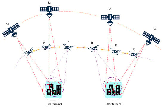
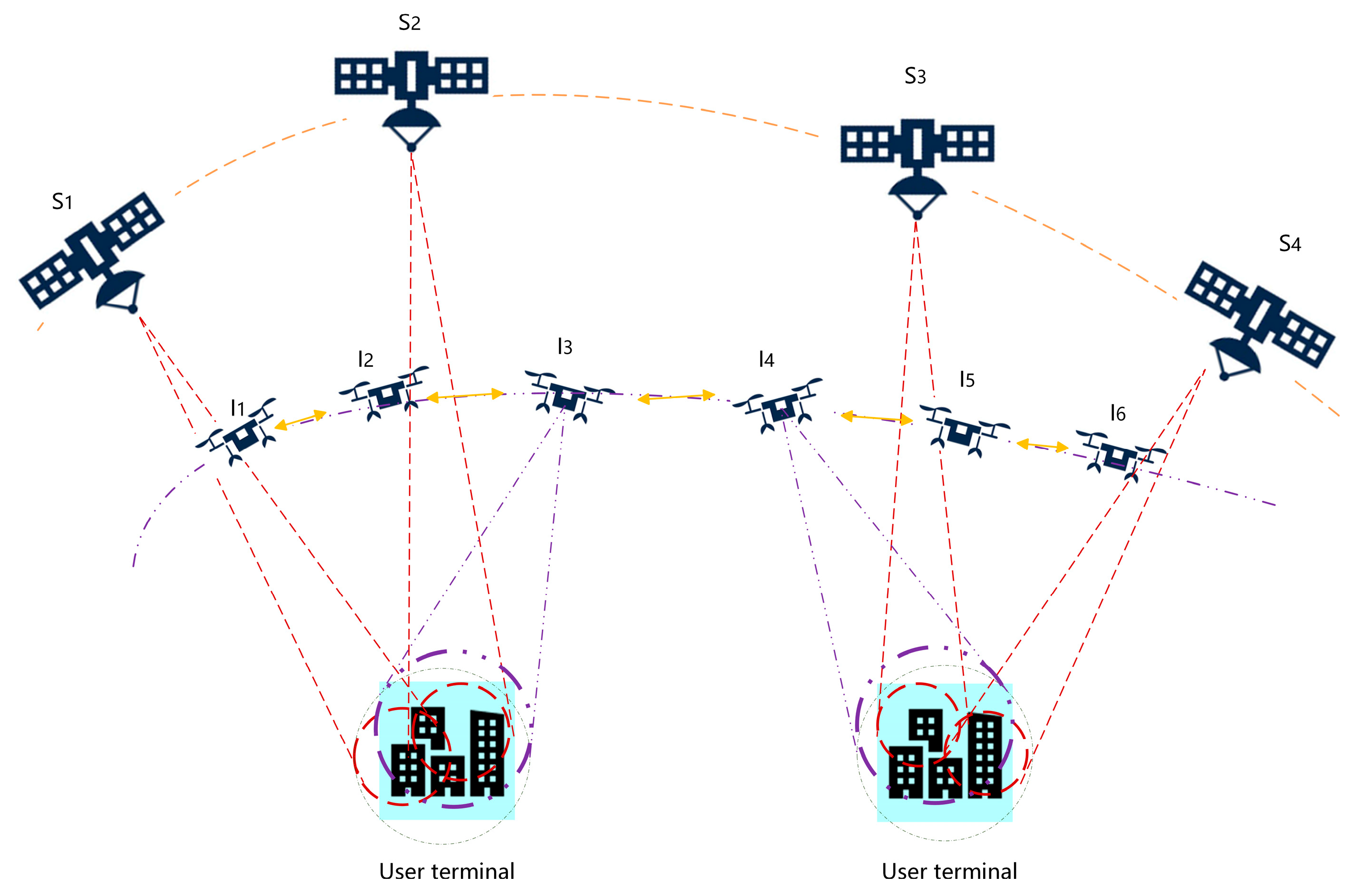
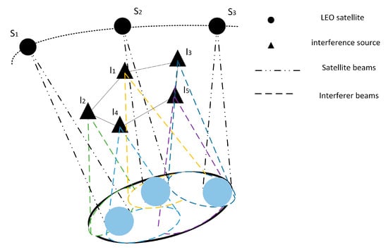
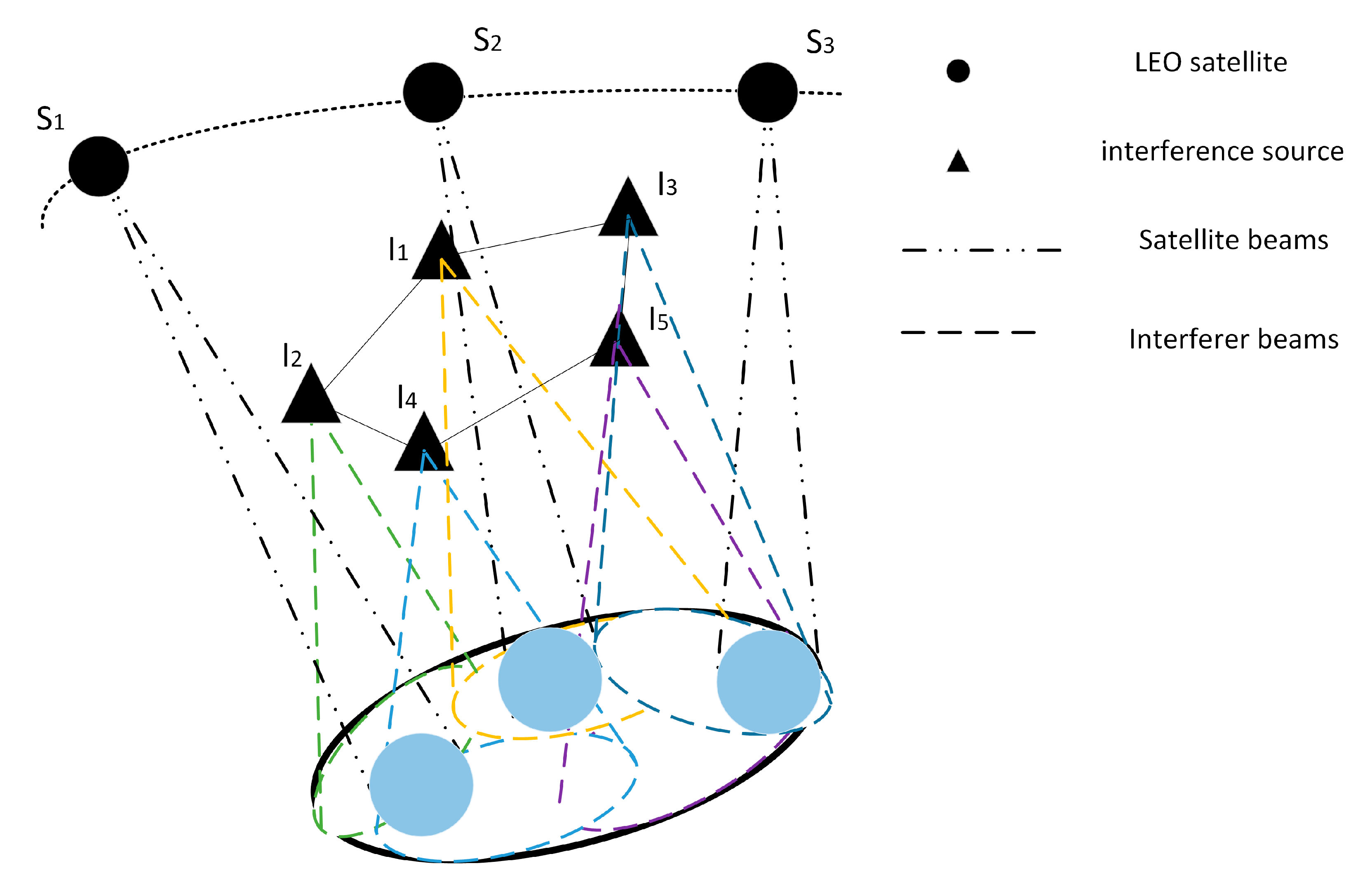
Displayed in Figure 1 is the interference system model for LEO satellites, where symbolizes LEO satellites, and denotes each source of interference in the distributed interference system. The yellow arrows indicate the group communication between each interference source in the whole distributed interference system, and the red dashed line indicates the downlink beam coverage of the user terminal by LEO satellites. In order to avoid the problem of crosstalk in the same frequency when the interference source sends interference signals with the satellite signals it receives, the distributed interference system divides the airspace according to the number of interference sources and the relative positions between the sources: the interference sources within the airspace covered by the satellite beams receive and process the satellite signals, and forward them through the group network communication to the interference sources under the unaffected airspace to broadcast the interference signals. For example, an interference source receives a signal from satellite , and after processing, forwards it to an interference source to broadcast the interference signal. This distributed interference architecture exhibits a spatially symmetric topology, which helps balance resource allocation among interference nodes and enhances the stability and coordination efficiency of the overall system.
Figure 1.
Low-orbit satellite distributed interference system architecture. Different colored dashed lines represent distinct communication links and interference transmission paths in the system.
The entire interference system continuously monitors the target area and forms a cooperative network through the organization of distributed interference nodes. Each interference node recognizes and locates satellite signals in real time and dynamically extracts time–frequency–space characteristic parameters based on satellite interference source interaction data. The system adopts an intelligent decision-making algorithm to intelligently match the optimal interference strategy based on the scene characteristics and maintains the interference performance in the best state through dynamic resource scheduling. When receiving the interference command, the system will automatically complete the cooperative scheduling of multi-source interference resources to form an all-round three-dimensional interference posture.
4. OI-MLT Algorithm
In this study, data sources were diverse and had significant multimodal characteristics, including two main types of data: first, image data with time–frequency characteristics and time–frequency spectra; and second, one-dimensional digital data describing satellite state and interference characteristics. The characteristics and structure of the multimodal data impose high requirements for the design of the algorithm. It is necessary to achieve uniform feature fusion and efficient optimization while ensuring the full expression of each modal feature.
It should be noted that some components used in the proposed framework, such as ResNet50 and the self-attention mechanism in the transformer, are standard modules in deep learning. The novelty of this study lies in their task-specific integration for LEO satellite interference optimization, including the multimodal fusion of time–frequency spectrum data and numerical signal parameters, the composite positional encoding designed for high-dynamic satellite scenarios, and the end-to-end prediction of interference effectiveness indicators. In this study, the objective of modeling is to learn the mapping from the multimodal signal and scenario features to interference effectiveness indicators, so as to support interference strategy optimization under dynamic LEO conditions. Therefore, the contribution of this work is not the invention of an entirely new backbone network, but the design of a LEO-oriented multimodal interference optimization framework that combines standard deep learning modules with task-driven feature fusion and positional modeling. To improve methodological clarity, the revised manuscript further organizes the description of feature extraction, multimodal alignment, positional encoding, and transformer-based interaction in a more structured manner.
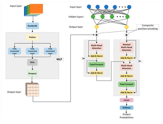
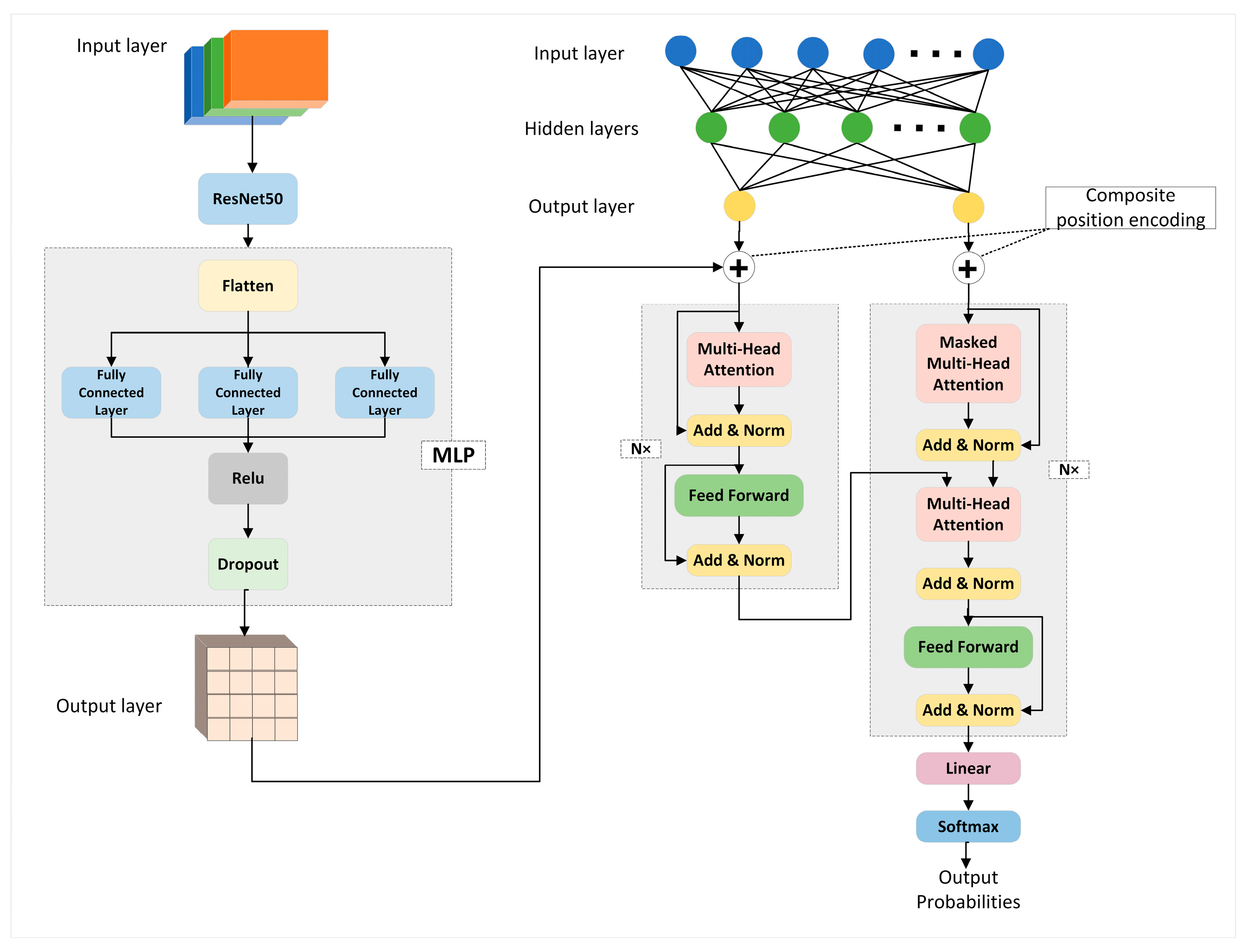
In order to solve the above problems, we propose a multimodal learning framework based on a transformer, OI-MLT, which is mainly composed of the following core modules in Figure 2:
Figure 2.
OI-MLT model framework.
In the entire model, spectrum features are extracted through pre-training ResNet50 and mapped to a fixed dimension through MLP. At the same time, multi-source features are aligned through linear projection and then concatenated and fused with spectrum features. Then, a transformer module containing multi-head attention, residual connections, and feedforward networks is used to model cross-modal spatio-temporal dependencies, forming an end-to-end intelligent processing chain from multimodal data input to target performance prediction. The transformer architecture further enables the modeling of symmetric relationships among multimodal features through its self-attention mechanism, thereby enhancing the consistency and effectiveness of cross-modal feature fusion.
4.1. Interference Performance Indicators
4.1.1. Frequency Tracking Accuracy
Frequency tracking accuracy refers to the ability of the interference system to track the carrier frequency change of the target signal, which means the maximum value of the actual frequency difference between the system output interference signal and the target signal [34]. Let denote the relative speed of the satellite and the interference machine (7.8 km/s for the LEO satellite), denote the carrier frequency (11.7 GHz), and be the speed of light (3 × 10⁸ m/s); then, the maximum Doppler shift is:
The change in radial velocity of the satellite leads to a change in Doppler frequency deviation, the radial acceleration ( is the orbital radius, which for LEO satellites is about 6800 km), and the Doppler change rate :
The Doppler change rate is |ḟ| ≈ 12.3 kHz/s, which indicates the dynamic frequency variation caused by satellite motion.
4.1.2. Synchronization Establishment Time
The frequency is captured in parallel using FFT, considering positive and negative frequency bias; the search range is set to and the frequency search step to . Then, the number of frequency search steps is:
where denotes the ceiling function, i.e., rounding up to the nearest integer.
The coherent integration time does not exceed the symbol period, and the integration time is determined by the signal bandwidth :
Then, the capture time is:
In the LEO satellite communication system, the second-order PLL damping coefficient is often set to to balance stability and dynamic performance in actual engineering applications. In order to lock in a shorter time and quickly respond to the frequency hopping of LEO satellite signals, its loop natural angular frequency is set to and the Doppler change rate is set to ; the phase-locking time is:
Then, the total signal synchronization time is:
4.1.3. Interference Success Rate
When there is no interference, let be the signal-to-noise ratio; in the case of BPSK modulation and QPSK modulation after Gray coding, the BER can be expressed as:
The signal-to-interference-plus-noise ratio (SINR) after the introduction of an interfering signal is:
where is the signal power, is the interference power density, and is the correlation between the interfering signal and the target signal (). Similarly, take the example of BPSK modulation and QPSK modulation after Gray coding; then, the BER after interference can be expressed as:
Then, the criterion for determining the success of interference to LEO satellites can be expressed as:
where it is required that .
4.2. Time–Frequency Domain Spectrum Feature Extraction
Time–frequency domain information processing captures the characteristic changes of signals in electromagnetic environments by analyzing the time and frequency dimensions of signals. Traditional signal processing methods usually only analyze the frequency domain or time domain, but for complex interference signals, joint time domain analysis can more effectively capture their changing characteristics at different moments on the time and frequency axis, especially the characteristics of non-smooth signals. On the basis of time–frequency joint processing, the jamming effect on LEO satellite signals is more obvious and accurate due to feature extraction and optimization. Moreover, the time–frequency representation inherently exhibits symmetric structures, which can be beneficial for capturing consistent signal patterns and improving feature extraction performance.
The time-frequency spectrum is a two-dimensional image used to show the frequency distribution of a signal at different moments, which can clearly capture the process of the different frequency components of the signal over time. Based on the time–frequency spectrum, a more comprehensive characterization of the interfering signal can be made.
However, given that time–frequency spectra are essentially a two-dimensional form of data, traditional one-dimensional signal analysis methods have limitations in feature extraction. Therefore, convolutional neural networks (CNNs) have become the preferred tool for analyzing time–frequency spectra. In this study, ResNet50 is adopted as a standard and mature CNN backbone for time–frequency spectrum feature extraction, while the methodological novelty does not lie in the backbone itself, but in its integration with numerical features within the proposed multimodal interference optimization framework.
CNNs have powerful feature extraction capabilities in image processing tasks and are capable of automatically extracting spatial patterns and local features from data. Time–frequency spectrum features are extracted by using a CNN:
- Capture local features in the time–frequency domain: The CNN can automatically identify local patterns in the frequency and time dimensions and effectively capture the changes of the signal on the time–frequency spectrum.
- Enhance the representation of multi-component signals: Through multi-layer convolution and pooling operations, the CNN is able to extract high-level features layer by layer, helping the model to more accurately differentiate between multiple components in the signal.
- Improve the generalization ability: The convolution operation of the CNN is sensitive to local changes, but it is robust to translation and noise interference, which can enhance the effect of interference feature extraction.
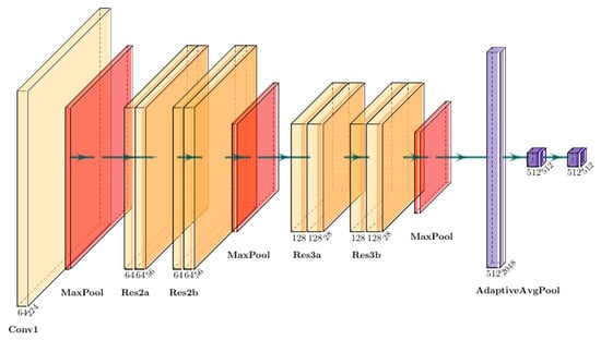
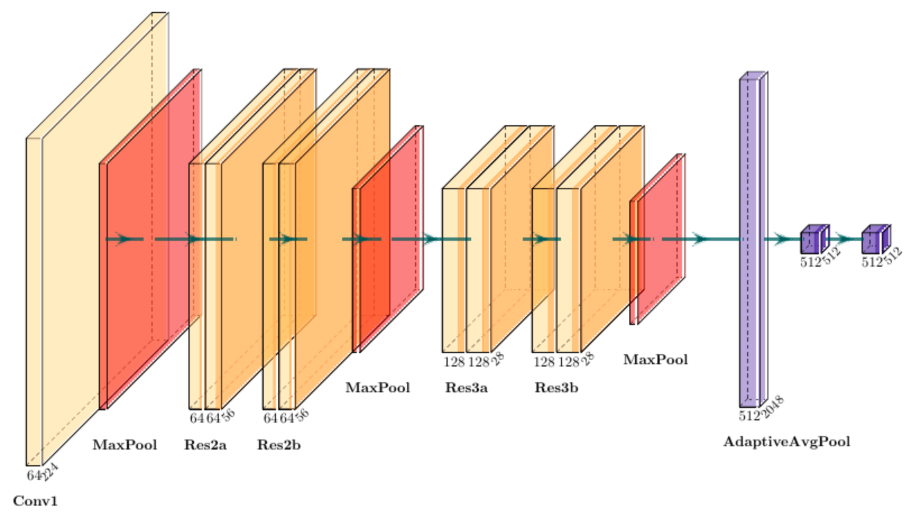
In this study, specific improvements are made to the CNN network based on the ResNet50 structure to accommodate efficient extraction and optimization of time–frequency spectrum features, as shown in Figure 3.
Figure 3.
Time–frequency spectrum feature extraction network structure.
Specific improvements are described below:
Initializing and Adapting to Input Layers: This research employs the pre-trained ResNet50 model to directly apply the model’s expertise on the extensive image dataset ImageNet. To enhance our adaptation to the 3-channel RGB time–frequency spectrum data in ResNet50, we eliminate the fully connected layer and the final global pooling layer, replacing them with the AdaptiveAvgPool adaptive pooling layer to stabilize the output features’ shape, aligning with the input needs of the following processing layers.
The time–frequency spectrum data are feature extracted by the ResNet network to obtain a 2D feature matrix. A multilayer perceptron (MLP) module is then introduced to combine these features in further detail: through a multilayer nonlinear transformation layer, the MLP uses a layer-by-layer mapping approach to combine features from different locations and channels in a weighted manner, allowing the network to focus on key signal features in the time–frequency spectra. After MLP processing, the 2D feature matrix is mapped to a feature space that is consistent with the transformer input dimension . Based on this feature alignment, we input the time–frequency spectrum features into the transformer model in parallel with other 1D feature data (e.g., location information, interference parameters, etc.) to form a unified multimodal dataset. In this way, the transformer can not only capture the complex dynamic features in the time–frequency spectrum, but also combine the auxiliary information of other modes to predict the interference performance index, which further enhances the expressive ability of the integrated interference strategy.
4.3. Spatial Domain-Composite Location Coding
In order to improve the localization accuracy of the OI-MLT model for LEO satellites in high-speed moving scenarios, this study designs composite position coding, which fuses sine–cosine position coding and learnable position coding, and balances the two coding methods by weighting parameters. This composite positional encoding is one of the key task-specific designs of the proposed method because it is introduced to simultaneously capture the periodic orbital regularity of LEO satellites and the local dynamic variations of interference scenarios, thereby improving positional representation in high-mobility conditions.
Sine–cosine position coding: used to capture global periodic information in sequence data, such as the periodic motion of LEO satellites in orbit. Sine–cosine coding can effectively handle the periodic variations in long time series. The sinusoidal functions inherently exhibit periodic symmetry, which is consistent with the cyclic motion characteristics of LEO satellite orbits. In this coding, the position vector for position pos and dimension is defined as:
where denotes the dimension of the location encoding.
Learnable positional coding: used to capture local features in a sequence. Learnable position coding is a dynamically generated coding method, which is not generated according to a fixed formula as in the case of sine–cosine position coding, but by initializing to a trainable parameter matrix and updating it according to the characteristics of the specific task data during the training process. This approach is suitable for capturing data characterized by non-periodic or rapid changes, and can be more flexible in reflecting changes in position information in high-speed moving LEO satellite scenarios. This flexibility complements the symmetric structure of sinusoidal encoding by capturing asymmetric or irregular positional variations.
This learnable position encoding is denoted . Assuming the dimension of the position encoding is and the maximum length of the sequence is max_len, the learnable position encoding matrix is defined as a trainable parameter matrix:
where each element is a learnable parameter, and the coding information suitable for the data is gradually learned by back propagating the gradient update. In the initialization phase, the learnable position coding matrix is usually initialized to small random values close to zero and obeys a Gaussian distribution:
We introduce a trainable parameter with an initial value of 0.5, and assign different weights to the positive cosine code and the learnable code according to the relative position changes of the LEO satellite and the interference source. The combined composite position code is defined as follows:
This weighted combination achieves a balance between symmetric periodic encoding and adaptive asymmetric representation, improving the robustness of positional modeling. This combined positional coding is added to the input feature x to complete the coding enhancement:
By combining the two, composite position coding captures both global and local position information, enhancing the ability of the transformer model to model complex motion scenes.
4.4. Self-Attention Mechanism
The self-attention mechanism is a core component of the transformer model that captures the dependencies between different locations in sequence data. In this study, the self-attention mechanism effectively fuses multimodal feature representations by processing features from different modalities in parallel. In this study, self-attention is adopted as a standard mechanism for modeling long-range dependencies, whereas the methodological contribution lies in using it to perform cross-modal interaction and feature fusion for LEO satellite interference optimization under dynamic time–frequency–space conditions.
The self-attention mechanism optimizes the interference effectiveness index through back propagation by projecting the input features, which are unified dimensional time–frequency–space feature information, to multiple subspaces for attention computation, and then combining the results to form the final output. Its formula is expressed as follows:
4.4.1. Feature Mapping
The input sequence is mapped into a query vector Q, a key vector K and a value vector V to obtain a feature representation of the polytope:
where ℎ is the number of attention heads, is the matrix of learnable parameters, and is the dimensionality of the single-head attention, partitioned by the number of heads :
4.4.2. Similarity Calculations
Similarity between queries and keys is computed by the dot product:
The scaling factor is used to stabilize the gradient update and to avoid too large a dot product result causing the gradient to disappear.
4.4.3. Normalizing Weights
A SoftMax operation is performed on the similarity scores to normalize the weights to the interval [0, 1], and the attentional weights for each header are computed from the dot product of the query and key:
The attention mechanism treats each input position uniformly and captures symmetric dependencies among feature elements. Normalizing weights determines the importance of the value vector V.
4.4.4. Multi-Head Mechanisms
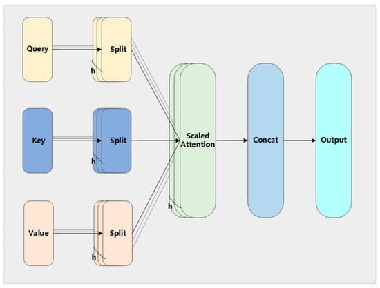
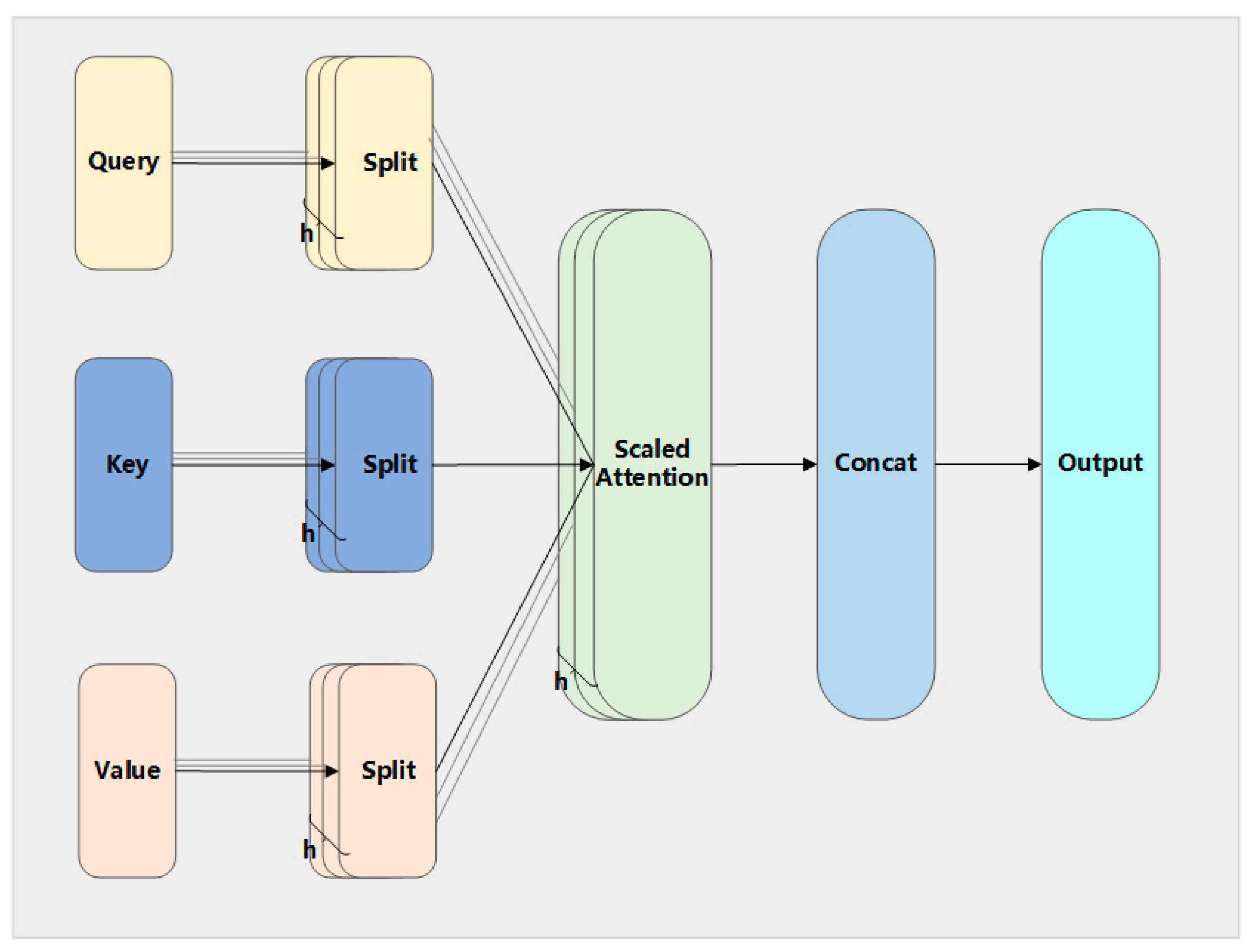
In order to enhance the model’s ability to capture diverse features, the multi-head attention mechanism divides the input into ℎ subspaces and computes the attention separately:
Finally, the outputs of the ℎ attention heads are spliced together and mapped back to the original dimension by linear transformation to obtain the final multi-head attention output, for which :
The self-attention mechanism weights are calculated as shown in Figure 4.
Figure 4.
Schematic diagram of weight calculation of self-attention mechanism.
The self-attention mechanism is able to efficiently fuse the input features of time–frequency mapping (2D features), with those of other modalities (1D features such as positional information, interference parameters, etc.) by calculating in parallel the relevance weights of each position in the sequence with respect to the global information. This process treats each input position in a uniform manner, which reflects a form of structural symmetry and enables balanced contribution of different feature components. The mechanism models inter-modal interactions in parallel on different semantic spaces through a dynamic weight allocation strategy in the multi-head attention subspace, providing a powerful characterization capability for multi-source information fusion in complex interference scenarios. Such a design captures symmetric relationships across different modalities and can be interpreted as a permutation-equivariant operation over the input feature set. Through an end-to-end back-propagation optimization process, the model parameters are continuously adjusted to optimize the jamming effectiveness metrics, thus achieving intelligent optimization and success rate enhancement of interference strategies.
Based on the details above, the flow of this model applied to interference system is summarized in Table 1:
Table 1.
Model application flow.
5. Experimental Results and Analysis
5.1. Experimental Setup
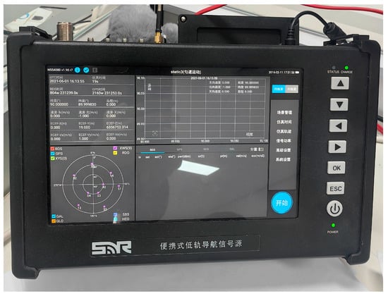
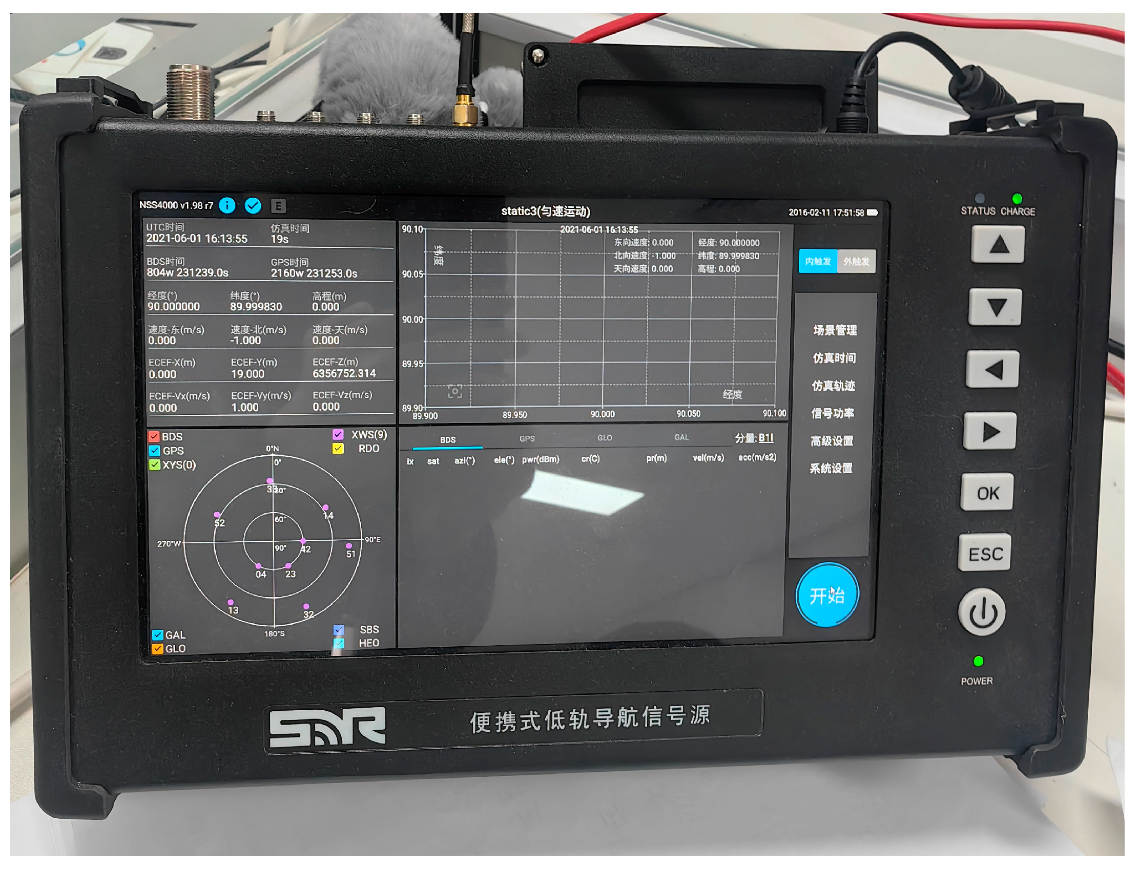
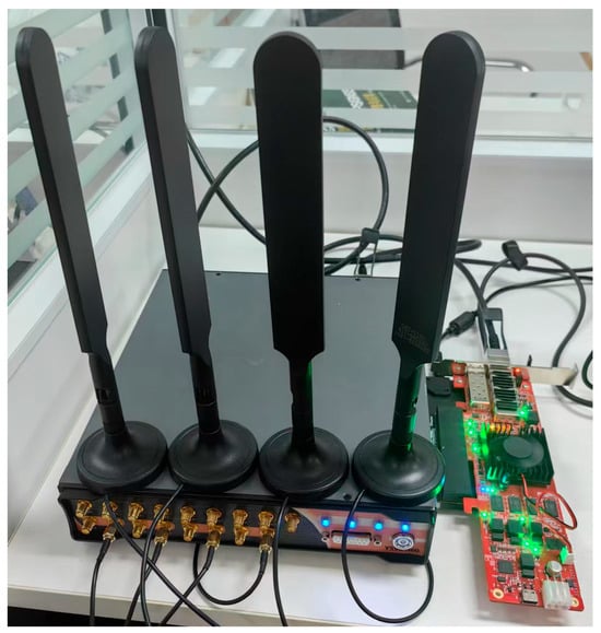
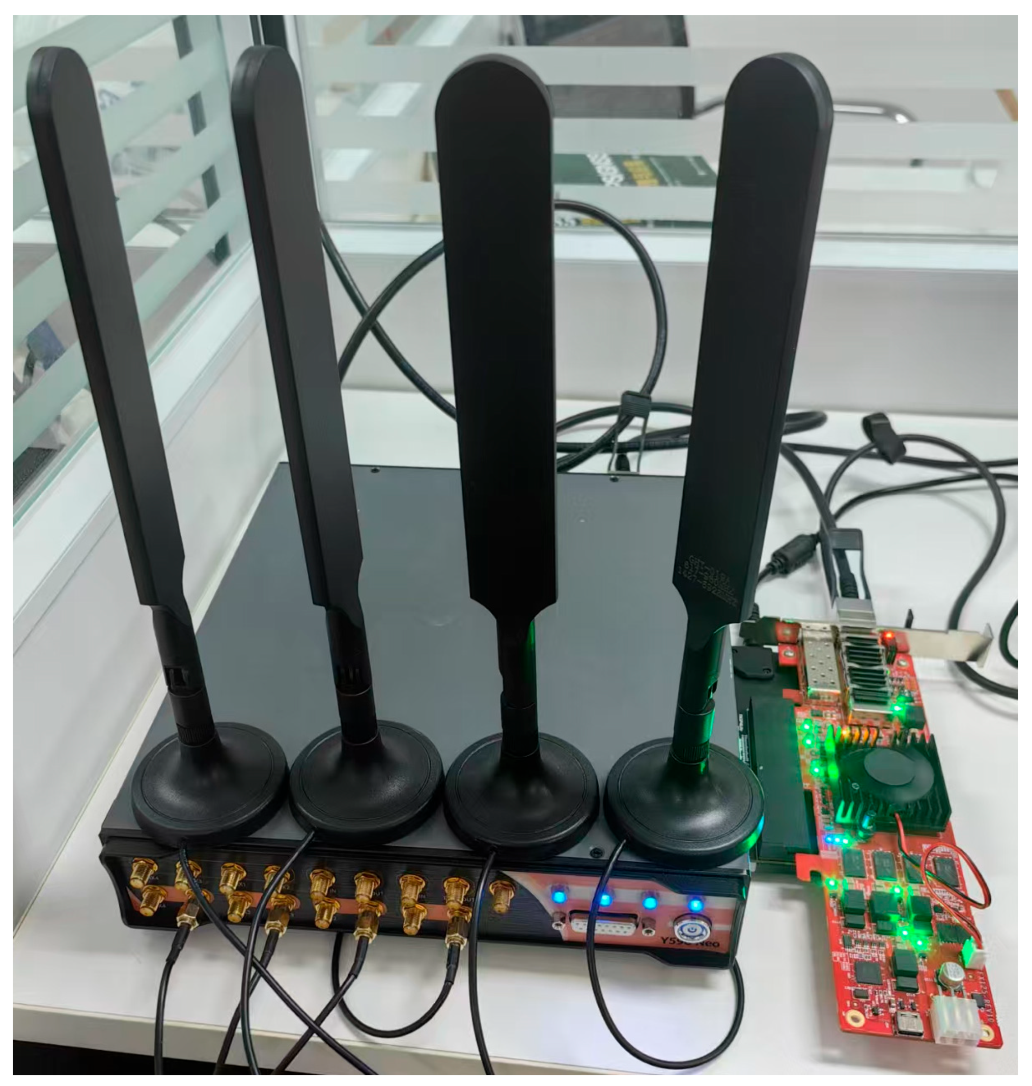
In order to verify the validity of the model of this study, a simulation experiment was conducted using a low-orbit satellite signal source (shown in Figure 5) and a multi-channel interference device (shown in Figure 6).
Figure 5.
Low-orbit satellite signal sources. Some Chinese labels appear in the equipment interface and are retained for authenticity.
Figure 6.
Multi-channel interference equipment.
The signal source can simulate the passage of different numbers of visible stars according to the size of the set area; simulate satellites with different orbital altitudes (while changing the speed) and orbital inclinations according to the location of the area (latitude and longitude settings); change the satellite’s transmit power according to the orbital altitude; and transmit signals with different modulation (BPSK/QPSK) according to the channel conditions of the communication link to ensure the quality of the communication before the interference.
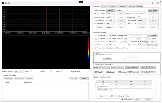
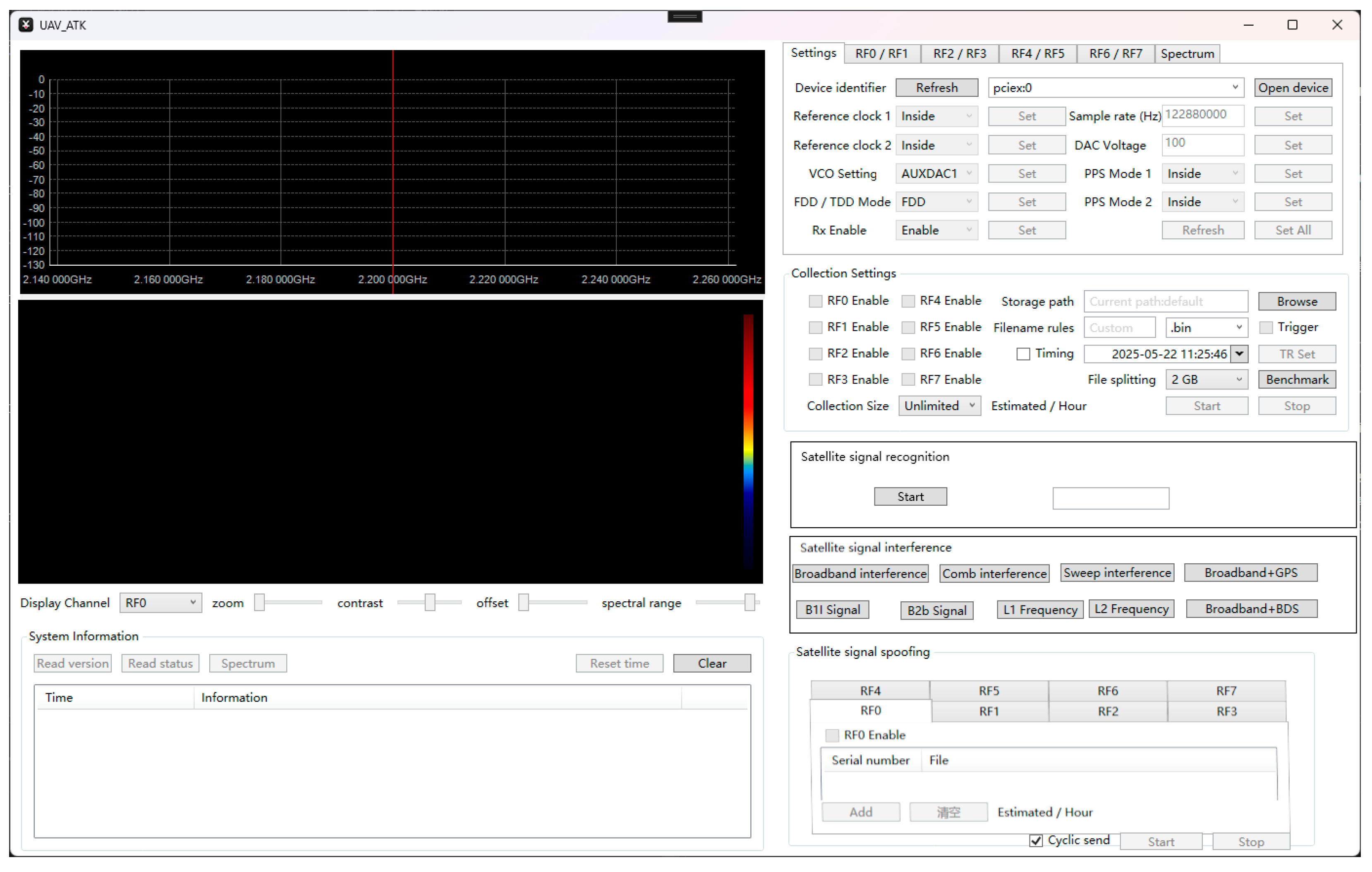
The interference equipment simulates different interference sources through multiple channels, which are controlled by the upper computer of the interference equipment (shown in Figure 7). These channels are organized in a structurally symmetric manner, allowing consistent interference behavior across different signal paths. The equipment is initially turned off, and at the beginning of the experiment, the region is monitored by clicking the “open equipment” button. In the left interface of the upper computer, satellite signals are sensed in real time and displayed in the form of time–frequency diagrams. In the right interface, the modulation mode of the signal can be recognized according to the processed data. The frequency point, power gain and interference mode of the interference signal can be adjusted by the relevant information obtained. The upper computer may adjust other unaffected channels to send interference signals according to the RF channel that senses the signal while listening. Multiple channels of the device communicate with the upper computer through multiple fiber-optic interfaces, constituting a distributed interference system.
Figure 7.
Upper computer interface for interference devices.
The interference scenario is constructed as shown in Figure 8. In the airspace above the protection area, five interference sources form a positive pentagonal topology, dividing the protection area according to their own airspace, judging the airspace to which they belong according to the satellite position, and receiving satellite signals by the interference sources in this airspace and forwarding them to the interference sources in other airspace to broadcast interference signals. The experiment was conducted by changing different scene parameters.
Figure 8.
Interference deployment scenario.
The satellite parameters simulated by the LEO satellite signal source and the interference parameters generated by the multibeam interference equipment are shown in Table 2:
Table 2.
Interference scene parameter settings.
By changing the number of low-orbit satellites passing through the airspace at different moments, altitude, inclination and signal transmitting power for 100 experiments, the low_orbit_satellite_jam_data dataset [35] was established based on the data of 100 sets of experiments. The dataset is categorized into five groups: satellite orbit information, signal parameters, beam states, interference data and time frequency spectra, where label mapping is used for categorical variables such as modulation type. The data are stored in HDF5 format. For reproducibility, the dataset source and related settings are explicitly provided in the manuscript. In addition, the main model hyperparameters and optimizer settings used in the experiments are summarized in Table 3 to improve the transparency of the experimental procedure. These settings are provided to make the experimental configuration more transparent and to facilitate future comparison and verification.
Table 3.
Experimental parameter settings.
The relevant parameters of the model in the experiment are shown in Table 3:
NSE, RMSE, MAE, and were selected as evaluation indicators for the evaluation of the model prediction results:
where: and denote collected and predicted data, respectively; and denote the average values of collected and predicted data, and denotes the set of data; NSE takes values ranging from (unfitted) to 1 (perfect fit); RMSE takes values ranging from 0 (perfect fit) to (unfitted); MAE is the mean of the absolute errors, which describes the difference between the collected data and the predicted results; and takes values ranging from 0 (unfitted) to 1 (perfect fit).
A total of three interference scenarios were created:
- Evaluate the ability of different methods to track changes in the carrier frequency of target signals in LEO satellite interference reflects the ability of the interference system to accurately track changes in the frequency of target signals in a dynamic environment.
- Explore the synchronization establishment time performance of different methods in LEO satellite interference scenarios, reflecting the ability of the interference system to lock onto the target signal quickly.
- Study the interference success rate of different methods and objectively compare the effectiveness of different methods in LEO satellite interference by comparing the BER before and after interference.
The experiments were validated using the optimized interference method with the multimodal learning transformer model (OI-MLT), the optimized interference method with the single-modal learning transformer model (OI-SLT), the traditional interference method (Non-Dominated Sorting Genetic Methods of the Third Generation (NSGA-III)), the support vector machine method (SVM), and the recurrent neural network model (RNN). Among them, OI-SLT is a model using single numerical modal data without a time–frequency spectrum.
5.2. Frequency Tracking Accuracy
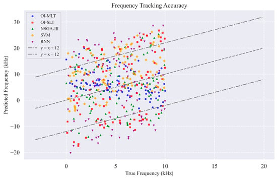
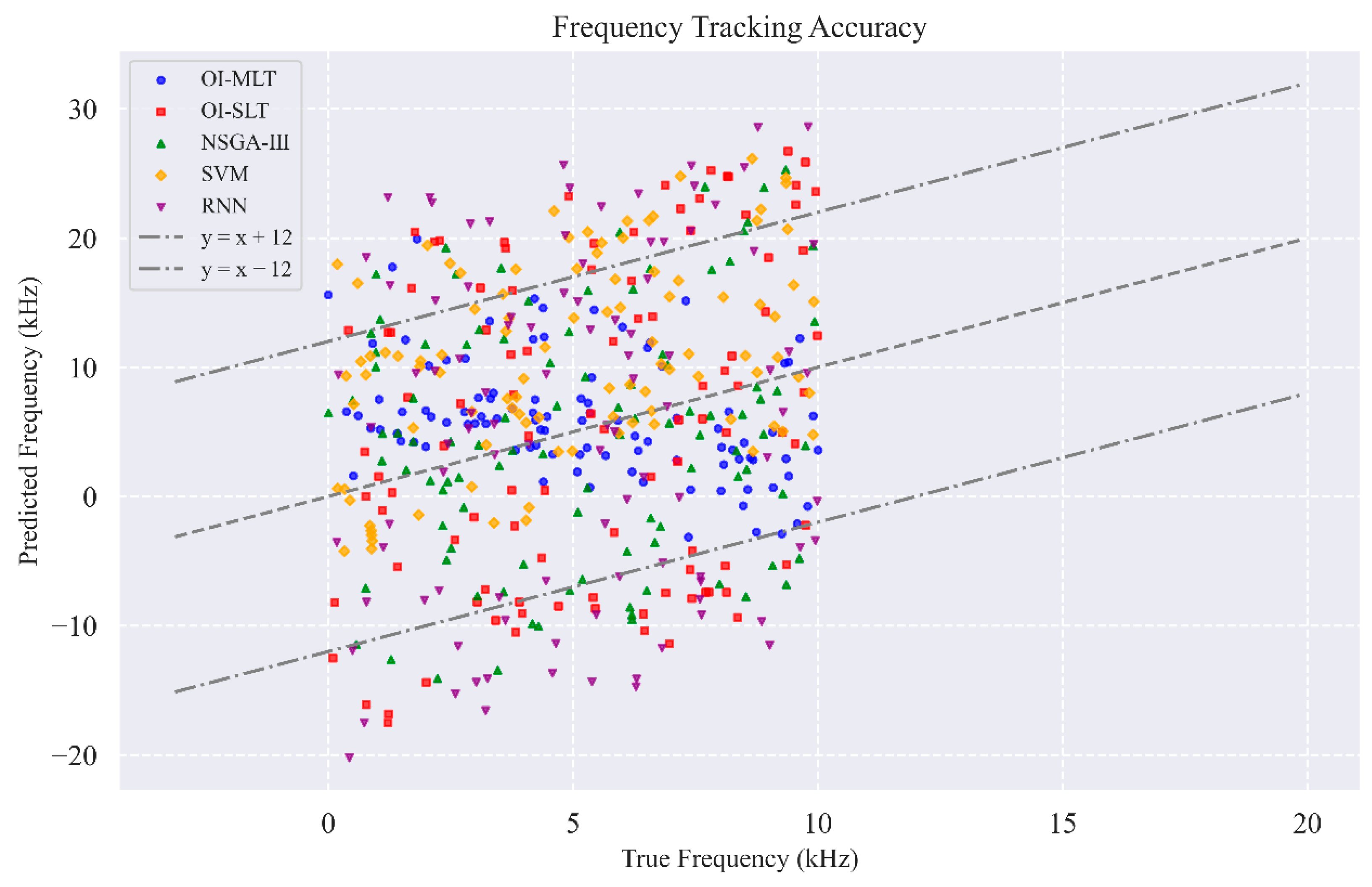
A Doppler shift of approximately ±304.2 kHz is caused by the motion of the LEO satellite at a maximum operating speed of 7.8 km/s, and the frequency tracking error should be controlled within about ±12 kHz. Figure 9 shows the comparison between the predicted Doppler shift and the true Doppler shift. The dashed lines indicate the ±12 kHz frequency tracking error bound. If the tracking accuracy is insufficient, the mismatch between the interference signal and the target carrier frequency will lead to a shift in the interference power spectrum and reduce the success rate of the interference.
Figure 9.
Frequency error tracking accuracy graph.
From the scatter plot of frequency tracking accuracy, the scatter distribution of the predicted frequency and the true frequency of the OI-MLT model is concentrated, and most of the points are distributed between the y = x − 12 and y = x + 12 reference lines, which is in line with the accuracy requirement of frequency tracking, and indicates that it is more capable of tracking the change in the carrier frequency of the target signal. In 100 experiments, the predicted value was worse only 3 times and the maximum value of the frequency difference was 17.63 kHz (predicted frequency 20.16 kHz, true frequency 2.53 kHz). In contrast, the OI-SLT model lacks continuous analysis in the time–frequency domain, and the scatter distribution is more dispersed; the SVM method predicts a high frequency overall, and the RNN and NSGA-III methods perform poorly in frequency tracking, with a more dispersed scatter distribution and a larger deviation from the reference region. The experiments show that the OI-MLT model effectively improves the correlation of time–frequency domain features and demonstrates more robust frequency tracking ability under different interference scenarios.
5.3. Synchronization Establishment Time
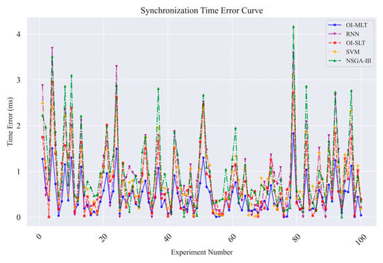
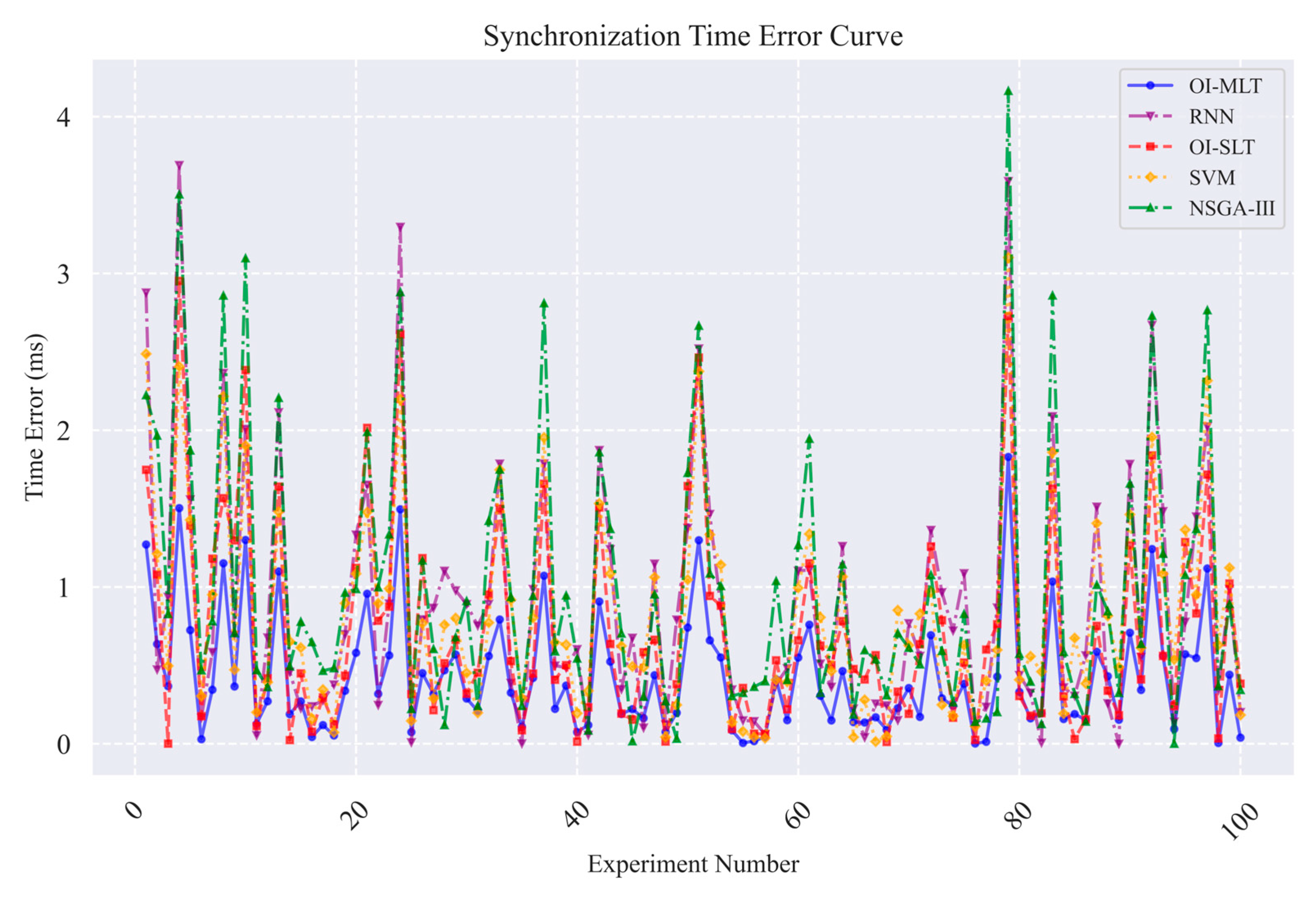
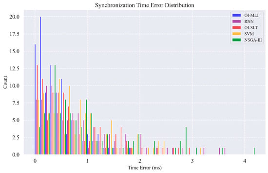
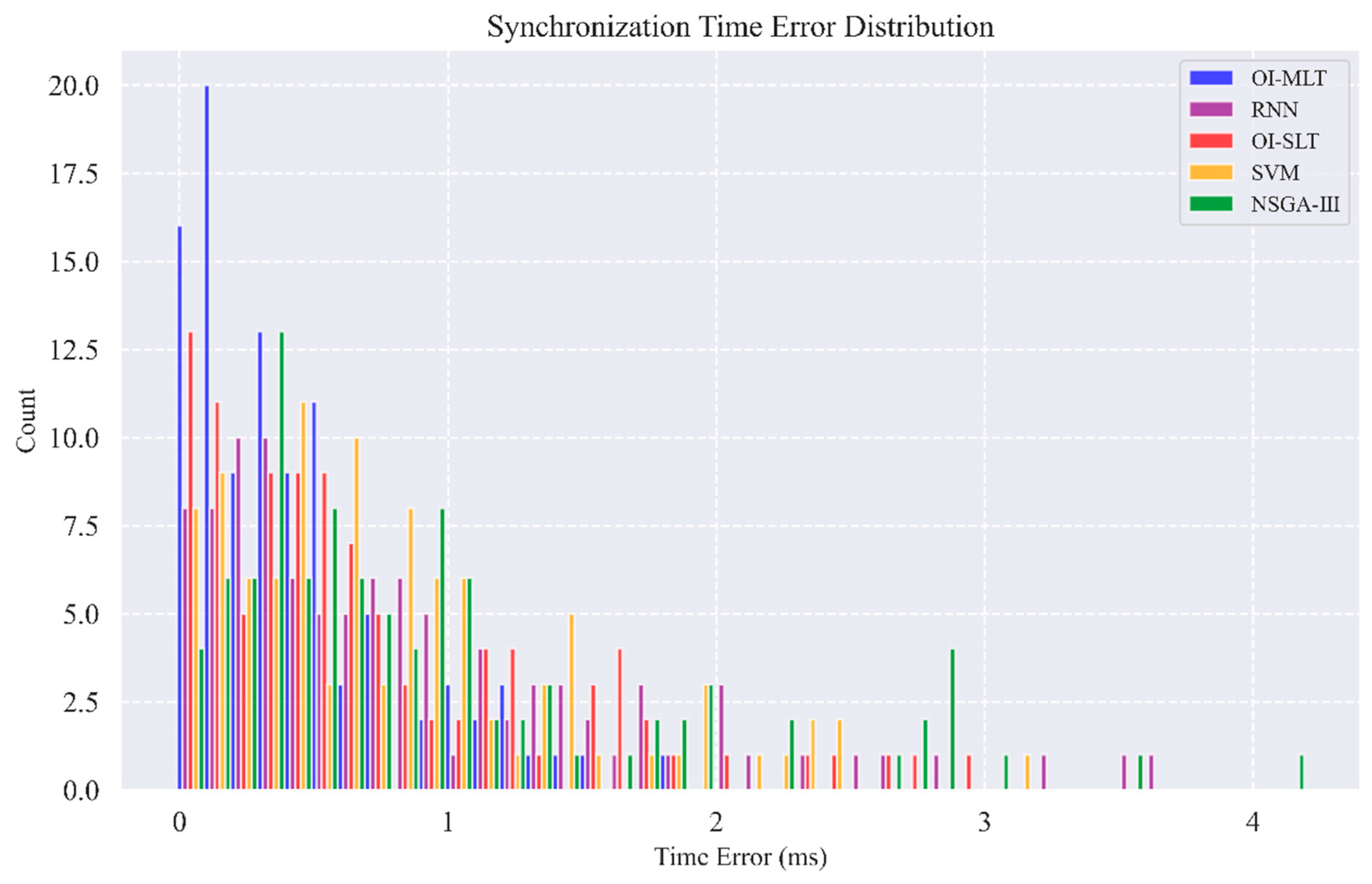
LEO satellite narrow-beam frequency-hopping communications have a very short residence time, and interference synchronization must be completed before the accumulation of signal energy is complete. If the synchronization time is too long, the interference signal will not be able to align with the target beam, resulting in interference failure. In this experiment, the error curves of the synchronization establishment time of each method and its distribution are shown in Figure 10 and Figure 11.
Figure 10.
Synchronization establishment time error graph.
Figure 11.
Distribution of synchronization establishment time error.
By analyzing the OI-MLT model and other methods in the synchronization time error curve and its distribution shows the error curve of the OI-MLT model fluctuates less and the overall error value is concentrated under 1 ms, which is lower than in the other methods. This concentrated distribution indicates a form of statistical symmetry around low error values, reflecting stable synchronization performance. In several experiments, the probability densities of different methods are observed: the synchronization time error of this model is always kept at a low level and no outliers occur. While the OI-SLT model lacks time–frequency spectrum information, and is unable to analyze the time and frequency continuously, the fluctuation is more obvious; the SVM method also shows better performance in synchronization time, and the error of multiple experiments is less than 1.5 ms; and the RNN and NSGA-III methods have multiple points with an error more than 2 ms, and the distribution of the error is more dispersed, which is poorer in terms of stability. This indicates that the OI-MLT model has higher accuracy and stability in synchronization establishment time and can realize signal synchronization more quickly and precisely.
5.4. Interference Success Rate
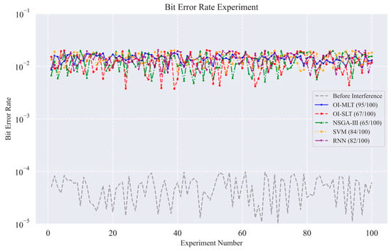
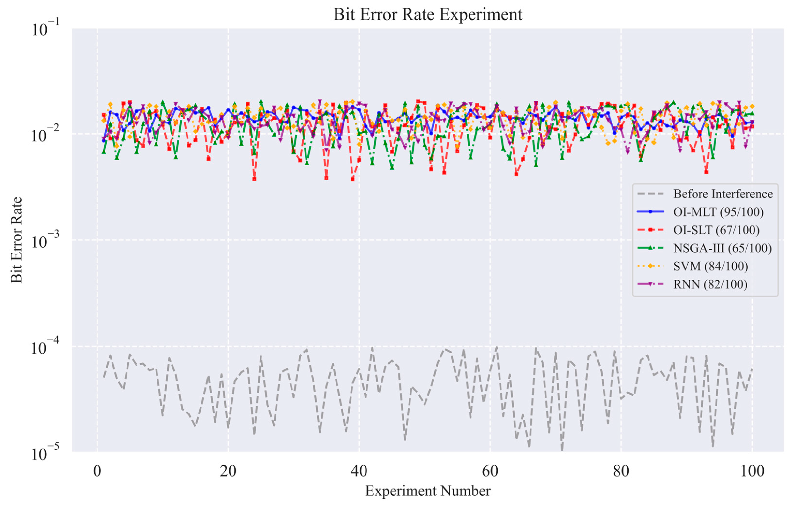
The interference success rate directly reflects the effectiveness of the interference method and the determination of the interference success rate using the BER indicator; the results of the experiment are shown in Figure 12:
Figure 12.
BER comparison graph.
The grey dashed line shows the BER of the LEO satellite system before interference, and the overall value is between 1 × 10⁻⁵ and 1 × 10⁻³, which can be communicated normally; after the application of each interference method, the success rates of OI-MLT, OI-SLT, NSGA-III, SVM, and RNN methods are 95%, 67%, 65%, 84%, and 72%, respectively. The OI-MLT model has the highest success rate, and the overall post-interference BER is in the range of 8 × 10⁻³ to 4 × 10⁻², whereas the SVM and RNN methods are unstable in terms of interference effect although the post-interference BER of several experiments can be up to 5 × 10⁻² orders of magnitude, and the fluctuations of NSGA-III and OI-SLT are more obvious. In comparison with the existing interference methods, the OI-MLT model’s interference success rate was improved by 27.52% on average; this suggests that the OI-MLT model optimizes the interference success rate through multimodal information fusion and dynamic strategy optimization.
5.5. Model Performance Evaluation
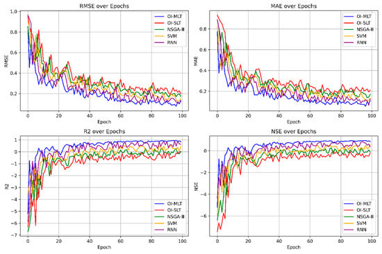
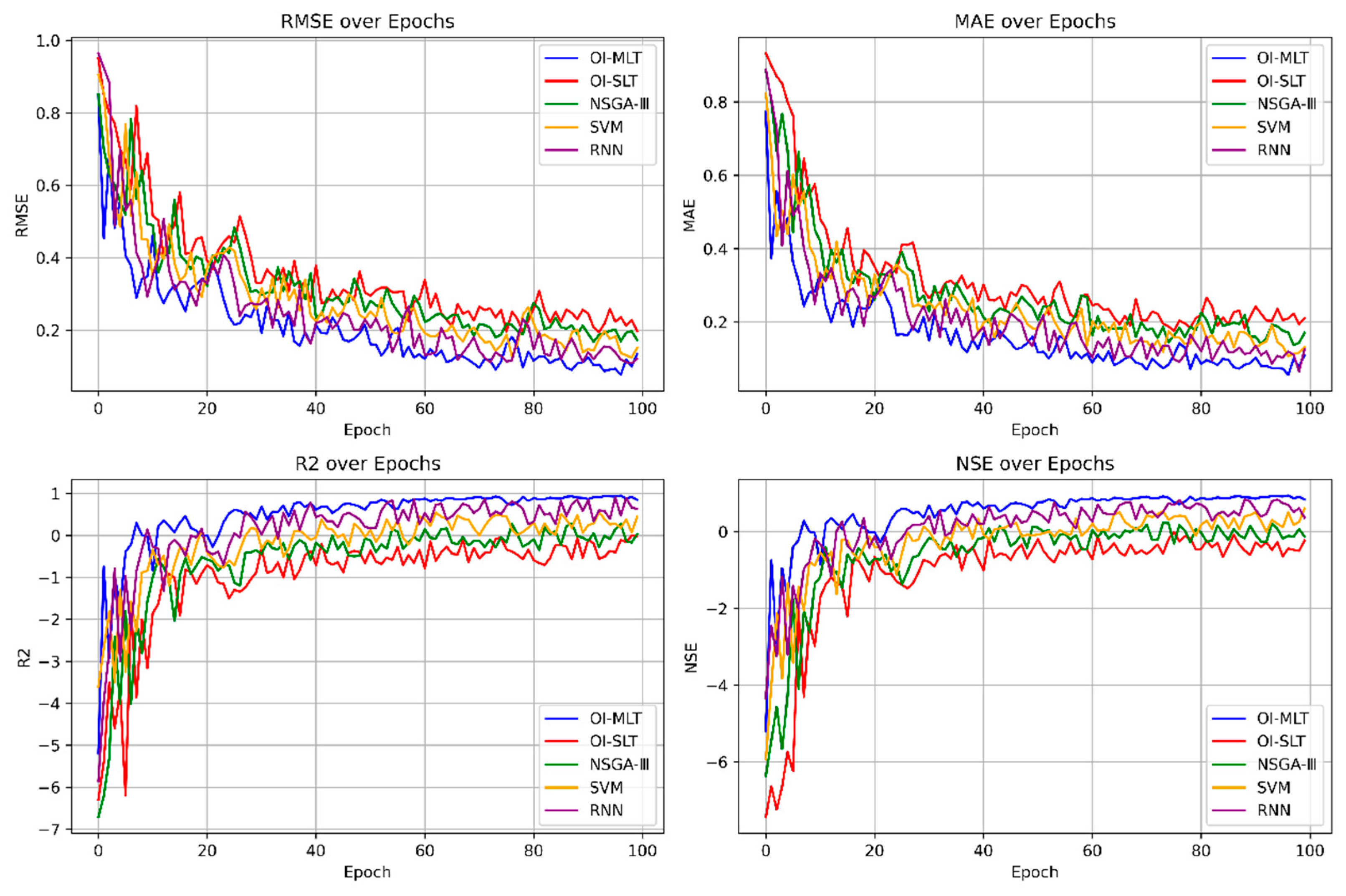
In the experiment, the trend of the performance index of each model with the increase in epoch is shown in Figure 13:
Figure 13.
Evaluation graph of model indicators.
It can be seen that, under 100 epochs, each model finally shows a convergence trend, in which the OI-MLT, RNN, and SVM models were trained in 96, 98, and 98 epochs for the best case of the model, with their RMSE values of 0.0766, 0.1084, and 0.1242, reflecting the small error between their predicted and true values. As can be seen from the and NSE metrics, the predicted and true values are well fitted. In contrast, the RMSE and MAE indexes of NSGA-III and OI-SLT models are still large after 100 epoch trainings, with MAE values of 0.1705 and 0.2106, respectively, and their optimal values are 0.2827 and 0.0215, reflecting the limitations of their understanding of the nonlinear characteristics of the data and the poor fitting effect. In 100 epochs, the best cases of RMSE, MAE, , and NSE metrics are found in the model OI-MLT, with values of 0.0766, 0.0559, 0.9496, and 0.9456, respectively, and the value of RMSE is reduced by 29.3% compared with that of the suboptimal model, which demonstrates that the OI-MLT model achieves the fastest convergence speed while maintaining optimal predictive accuracy.
In addition to the predictive accuracy shown above, the generalization capability of the proposed OI-MLT model should also be discussed. In this study, the dataset was constructed from multiple dynamically changing LEO interference scenarios, including variations in visible satellite number, orbital height, orbital inclination, operating speed, landing power, and modulation conditions. Such diversified scenario settings reduce the risk of overfitting to a single interference condition. Moreover, by jointly modeling time–frequency spectrum data and one-dimensional numerical parameters, the proposed multimodal framework learns complementary feature representations from both signal morphology and physical environment variables, which improves robustness against scene changes. Therefore, compared with single-mode methods, the proposed OI-MLT framework has better potential to generalize across different LEO interference scenarios. Nevertheless, broader validation on cross-platform datasets or real measured environments will be further studied in future work. It should also be noted that the present study is based on a simulation dataset with limited scale. Therefore, the current results are intended to provide a task-oriented validation under controlled LEO interference conditions rather than a claim of universal superiority. Larger-scale validation, broader benchmark comparison, and more detailed module-level analysis will be further considered in future work.
6. Conclusions
This document proposes an approach for optimizing interference through multimodal learning based on a transformer with fast frequency tracking, good synchronization performance, and a stable effect, in response to the threat to military communication security posed by LEO satellites due to their small transmission delay, high communication rate, and fast frequency change. And comparison experiments with a variety of interference optimization methods are carried out in terms of frequency tracking accuracy, synchronization establishment time, interference success rate, and model performance. The findings indicate that, in contrast to alternative methods, the predicted frequency of this model is more in line with the frequency tracking accuracy, and can achieve signal synchronization more quickly and accurately, which effectively improves the success rate of interference. Furthermore, the proposed method implicitly exploits symmetry in multiple domains, including the time–frequency duality of signal representations, the spatial symmetry of distributed interference sources, and the symmetric feature interactions modeled by the self-attention mechanism, thereby enabling more efficient multimodal feature fusion and enhanced robustness under dynamic LEO satellite scenarios. The results also suggest that the proposed multimodal framework has promising generalization potential under varying LEO interference conditions, owing to its joint modeling of spectral structure and numerical scenario parameters. Future work will further investigate symmetry-aware model design to explicitly incorporate structural and geometric symmetries, aiming to improve generalization and adaptability in more complex communication environments. At the same time, the present validation is still limited by the scale of the current simulation dataset, and broader verification will be necessary in future studies.
Author Contributions
Conceptualization, C.T.; Methodology, C.T. and Y.L.; Software, A.C. and J.Y.; Formal analysis, Y.L.; Investigation, A.C.; Data curation, A.C. and J.Y.; Writing—original draft, A.C.; Writing—review & editing, C.T. and Z.D.; Visualization, A.C., Y.L. and J.Y.; Supervision, C.T., Z.D. and Y.L.; Funding acquisition, C.T. and Z.D. All authors have read and agreed to the published version of the manuscript.
Funding
This work was supported in part by National Natural Science Foundation of China under Grant 62171375, 62271397, 62173276, 62101458, 62001392, 61803310 and 61801394, in part by Shenzhen Science and Technology Innovation Program under Grant JCYJ20220530161615033.
Data Availability Statement
The data presented in this study are openly available in Low Earth Orbit Satellite Interference Dataset at https://tianchi.aliyun.com/dataset/198601 (accessed on 20 April 2026).
Acknowledgments
The authors would like to thank editors for rigorous work and the anonymous reviewers for their comments and suggestions.
Conflicts of Interest
The authors declare no conflict of interest.
References
- Li, S.; Wang, H. Research on navigation and positioning technology based on opportunity signal of low orbit satellite. J. Phys. Conf. Ser. 2021, 1952, 042134. [Google Scholar] [CrossRef] [Scilit]
- Tang, C.; Wang, W.; Zhang, L.; Wang, C. UAV cluster geometric information fusion cooperative positioning algorithm with LEO satellite system. IET Control Theory Appl. 2024, 18, 2852–2863. [Google Scholar] [CrossRef] [Scilit]
- Meng, L.; Yang, L.; Yang, W.; Zhang, L. A Survey of GNSS Spoofing and Anti-Spoofing Technology. Remote Sens. 2022, 14, 4826. [Google Scholar] [CrossRef] [Scilit]
- Humphreys, T.E.; Iannucci, P.A.; Komodromos, Z.M.; Graff, A.M. Signal structure of the Starlink Ku-band downlink. IEEE Trans. Aerosp. Electron. Syst. 2023, 59, 6016–6030. [Google Scholar] [CrossRef] [Scilit]
- Chen, Q.; Giambene, G.; Yang, L.; Fan, C.; Chen, X. Analysis of inter-satellite link paths for LEO mega-constellation networks. IEEE Trans. Veh. Technol. 2021, 70, 2743–2755. [Google Scholar] [CrossRef] [Scilit]
- Liu, R.; Yang, Z.; Chen, Q.; Liao, G.; Zhu, Q. Localization of GNSS spoofing interference source based on a moving array antenna. Remote Sens. 2023, 15, 5497. [Google Scholar] [CrossRef] [Scilit]
- Thoelert, S.; Steigenberger, P.; Montenbruck, O.; Meurer, M. Signal analysis of the first GPS III satellite. GPS Solut. 2019, 23, 92. [Google Scholar] [CrossRef] [Scilit]
- Shaheen, E.M.; Elgamel, S.A. Mathematical analyses of the GPS receiver interference tolerance and mean time to loss lock. Def. Technol. 2019, 15, 440–449. [Google Scholar] [CrossRef] [Scilit]
- Zheng, X.; Yang, J.; Tang, C.; Lu, S.; Ding, J.; Kong, Y. Key region UAV fusion immersion deception algorithm. In Proceedings of the IEEE International Conference on Signal Processing, Communications and Computing (ICSPCC), Zhengzhou, China, 14–17 November 2023; IEEE: New York, NY, USA, 2023; pp. 1–6. [Google Scholar] [CrossRef] [Scilit]
- Chen, Z.; Liu, Y.; Liu, S.; Wang, S.; Yang, L. An improved fading factor-based adaptive robust filtering algorithm for SINS/GNSS integration with dynamic disturbance suppression. Remote Sens. 2025, 17, 1449. [Google Scholar] [CrossRef] [Scilit]
- Diao, Z.; Wu, G.; Long, X.; Yin, Y.; Tan, J.; Zhou, W.; Liu, G. Jamming analysis and experimental validation of GPS deception signal to electric patrol UAV. In Proceedings of the International Conference on Energy, Electrical and Power Engineering (CEEPE), Guangzhou, China, 12–14 May 2023; IEEE: New York, NY, USA, 2023; pp. 434–438. [Google Scholar] [CrossRef] [Scilit]
- Zhu, J.; Sun, Y.; Peng, M. Timing advance estimation in low earth orbit satellite networks. IEEE Trans. Veh. Technol. 2024, 73, 4366–4382. [Google Scholar] [CrossRef] [Scilit]
- Wang, S.; Tang, X.; Li, J.; Huang, X.; Liu, J.; Liu, J. Navigation resource allocation algorithm for LEO constellations based on dynamic programming. Remote Sens. 2024, 16, 2231. [Google Scholar] [CrossRef] [Scilit]
- Tang, C.; Zhou, X.; Zhang, L.; Liu, Y.; Dan, Z. LEO satellite navigation signal multi-dimensional interference optimisation method based on hybrid game theory. Remote Sens. 2025, 17, 1444. [Google Scholar] [CrossRef] [Scilit]
- McDowell, J.C. The low earth orbit satellite population and impacts of the SpaceX Starlink constellation. Astrophys. J. Lett. 2020, 892, L36. [Google Scholar] [CrossRef] [Scilit]
- Alrefaei, F.; Alzahrani, A.; Song, H.; Alrefaei, S. A survey on jamming and spoofing attacks on unmanned aerial vehicle networks. In Proceedings of the IEEE International IOT, Electronics and Mechatronics Conference (IEMTRONICS), Toronto, ON, Canada, 1–4 June 2022; IEEE: New York, NY, USA, 2022; pp. 1–7. [Google Scholar] [CrossRef] [Scilit]
- Wang, Y.; Sun, F.-P.; Wang, X. Optimal decision for the satellite navigation system under navigation countermeasures based on spoofing effect evaluation results. IET Control Theory Appl. 2023, 17, 1522–1542. [Google Scholar] [CrossRef] [Scilit]
- Mehmood, S.; Malik, A.N.; Qureshi, I.M.; Khan, M.Z.U.; Zaman, F. A novel deceptive jamming approach for hiding actual target and generating false targets. Wirel. Commun. Mob. Comput. 2021, 2021, 8844630. [Google Scholar] [CrossRef] [Scilit]
- Tang, C.; Ding, J.; Qi, H.; Zhang, L. Smart forwarding deceptive jamming distribution optimal algorithm. IET Radar Sonar Navig. 2024, 18, 953–964. [Google Scholar] [CrossRef] [Scilit]
- Escudero, C.; Massioni, P.; Zamaï, E.; Raison, B. Analysis, prevention, and feasibility assessment of stealthy ageing attacks on dynamical systems. IET Control Theory Appl. 2022, 16, 381–397. [Google Scholar] [CrossRef] [Scilit]
- Wang, Y.; Hao, J.-M.; Liu, W.-P.; Wang, X. Dynamic evaluation of GNSS spoofing and jamming efficacy based on game theory. IEEE Access 2020, 8, 13845–13857. [Google Scholar] [CrossRef] [Scilit]
- Li, X.; Chen, L.; Lu, Z.; Wang, F.; Liu, W.; Xiao, W.; Liu, P. Overview of jamming technology for satellite navigation. Machines 2023, 11, 768. [Google Scholar] [CrossRef] [Scilit]
- Wei, D.; Zhang, S.; Chen, S.; Zhao, H.; Zhu, L. Research on deception jamming of chaotic composite short-range detection system based on bispectral analysis and genetic algorithm–back propagation. Int. J. Distrib. Sens. Netw. 2019, 15, 155014771984744. [Google Scholar] [CrossRef] [Scilit]
- Day, R.O.; Kleeman, M.P.; Lamont, G.B. Multi-objective fast messy genetic algorithm solving deception problems. In Proceedings of the IEEE Congress on Evolutionary Computation, Portland, OR, USA, 19–23 June 2004; IEEE: New York, NY, USA, 2004; pp. 1502–1509. [Google Scholar] [CrossRef] [Scilit]
- Tang, C.; Ding, J.; Zhang, L. LEO Satellite Downlink Distributed Jamming Optimization Method Using a Non-Dominated Sorting Genetic Algorithm. Remote Sens. 2024, 16, 1006. [Google Scholar] [CrossRef] [Scilit]
- Zhao, B.; Zou, W. Coordinated Interference of Multiple UAVs on Networked Radar. Open Access J. Data Sci. Artif. Intell. 2024, 2, 000135. [Google Scholar] [CrossRef] [Scilit]
- Liu, Y.; Wang, C.; Wen, Y.; Huo, Y.; Liu, J. Efficient segmentation algorithm for complex cellular image analysis system. IET Control Theory Appl. 2023, 17, 2268–2279. [Google Scholar] [CrossRef] [Scilit]
- Qi, Q.; Huo, H. Accuracy analysis of farmer behaviour based on big data and efficient video transmission: A convolutional neural network approach. IET Control Theory Appl. 2023, 17, 2047–2055. [Google Scholar] [CrossRef] [Scilit]
- Tanveer, M.; Rastogi, A.; Paliwal, V.; Ganaie, M.A.; Malik, A.K.; Del Ser, J.; Lin, C.-T. Ensemble deep learning in speech signal tasks: A review. Neurocomputing 2023, 550, 126436. [Google Scholar] [CrossRef] [Scilit]
- Fu, Y.; Luo, X.; Qin, X.; Wan, H.; Cui, J.; Huang, Z. Deep Learning-Based Feature Matching Algorithm for Multi-Beam and Side-Scan Images. Remote Sens. 2025, 17, 675. [Google Scholar] [CrossRef] [Scilit]
- Swinney, C.J.; Woods, J.C. GNSS jamming classification via CNN, transfer learning and the novel concatenation of signal representations. In Proceedings of the International Conference on Cyber Situational Awareness, Data Analytics and Assessment (CyberSA), Dublin, Ireland, 14–18 June 2021; IEEE: New York, NY, USA, 2021; pp. 1–9. [Google Scholar] [CrossRef] [Scilit]
- Wang, G.-S.; Ren, Q.-H.; Su, Y.-Z. The interference classification and recognition based on SF-SVM algorithm. In Proceedings of the IEEE 9th International Conference on Communication Software and Networks (ICCSN), Guangzhou, China, 6–8 May 2017; IEEE: New York, NY, USA, 2017; pp. 835–841. [Google Scholar] [CrossRef] [Scilit]
- Mun, J.; Ha, S.; Lee, J. Automotive radar signal interference mitigation using RNN with self attention. In Proceedings of the IEEE International Conference on Acoustics, Speech and Signal Processing (ICASSP), Barcelona, Spain, 4–8 May 2020; IEEE: New York, NY, USA, 2020; pp. 3802–3806. [Google Scholar] [CrossRef] [Scilit]
- Pérez, I.; San-Martín, M.; López, R.; Vergara, E.P.; Wittig, A.; San-Juan, J.F. Extending the hybrid methodology for orbit propagation by fitting techniques. Neurocomputing 2019, 354, 49–60. [Google Scholar] [CrossRef] [Scilit]
- Tang, C.; Yang, J. Low Earth Orbit Satellite Interference Dataset [Dataset], v1. 2025. Available online: https://tianchi.aliyun.com/dataset/198601 (accessed on 20 April 2026).

Disclaimer/Publisher’s Note: The statements, opinions and data contained in all publications are solely those of the individual author(s) and contributor(s) and not of MDPI and/or the editor(s). MDPI and/or the editor(s) disclaim responsibility for any injury to people or property resulting from any ideas, methods, instructions or products referred to in the content. |
© 2026 by the authors. Licensee MDPI, Basel, Switzerland. This article is an open access article distributed under the terms and conditions of the Creative Commons Attribution (CC BY) license.