


Abstract
To address the technical challenges of difficult deduction, limited field measurement, and ambiguous instability determination of roof separation critical values in mining roadways within the weakly cemented coal-bearing strata of Xinjiang, this paper proposes a discrete element method that integrates the fracture of anchor bolt and anchor cable support materials with the damage degree of the surrounding rock. Taking a specific mine in the Hosh Tolgay coalfield as the research object, a systematic study was conducted. The research process was as follows. (1) Model parameter calibration was performed. Intact rock parameters were obtained through laboratory basic mechanical tests, and rock mass parameters were corrected based on reduction empirical formulas and the Hoek–Brown criterion. Numerical model verification showed that the errors between the simulated and theoretical values of the elastic modulus, compressive strength, and tensile strength of the rock mass were all less than 10%, indicating that the corrected parameters are reasonable. (2) The critical damage values of the rock mass considering a non-constant confining pressure environment were proposed. Through triaxial compression simulations, the differential evolution patterns of rapid damage increase in sandy mudstone under low confining pressure and stable damage accumulation in coal were revealed, thereby clarifying the damage thresholds for rock mass instability under different confining pressures. (3) A large-scale model was established to analyze the evolution laws of the fracture field, support field, and displacement field of the roadway surrounding rock. A comprehensive determination method for the instability of the roof anchored bearing structure was proposed. By comparing the damage thresholds of the scaled rock mass and the roadway surrounding rock and analyzing the fracture conditions of the roadway support system, a dual-criterion consisting of surrounding rock damage and support material fracture was constructed. Based on this criterion theory, the critical values for deep and shallow separation were obtained. The research results indicate that the evolution patterns of damage in coal and sandy mudstone differ with confining pressure. The sandy mudstone layers in the shallow part of the roof are more sensitive to mining-induced unloading disturbances. Consequently, the surrounding rock damage and support fracture of the mine roof exhibit distinct distribution characteristics: the dominant failure of the roadway is shear failure, with wide-range coalescence of shallow fractures and gradual development of deep fractures, alongside the concentrated failure of shallow anchor bolts and partial failure of deep anchor cables. Based on the instability state of the roof monitoring zones, the critical value for shallow separation was determined to be 90.7 mm, and the critical value for deep separation was 129.03 mm. These results are very close to the field measured values, verifying the engineering applicability of the method. This paper reveals the damage characteristics of the rock mass and surrounding rock in weakly cemented strata, as well as the mechanism of roof separation initiation and evolution. The proposed method for determining critical values provides a scientific and feasible practical reference for the support optimization and monitoring and early warning of roadway roofs in weakly cemented strata, possessing significant engineering value for ensuring safe and efficient mine production.
1. Introduction
The coal bases in Xinjiang are characterized by the extensive development of weakly cemented coal-bearing strata. The rock masses in these regions are loosely cemented, prone to disintegration, and possess low mechanical strength, making them highly sensitive to disturbances [1,2]. Following roadway excavation, the roof surrounding rock experiences structural deterioration induced by mining stress, leading to separation, fracture propagation, and even catastrophic instability. This has become a core technical challenge restricting the safe and efficient extraction of mines [3,4]. Ju Wenjun [5] pointed out that roof separation is not merely the relative isolation between rock layers, but also represents the elasto-plastic and buckling deformations of the stratified structure in a broader sense. As a key precursor to the instability of roadway surrounding rock, its essence lies in the external mechanical response resulting from the synergistic interaction of the in-situ stress field, rock strata structural characteristics, and the support system [6]. The maximum value of the loosening and expansion displacement of the anchored roadway roof strata while still in a stable state is defined as the critical value of roof separation [7]. As the core threshold for determining the transition of the roof from a stable state to a failure state, its accurate determination holds significant theoretical value and engineering guidance for the prediction and prevention of surrounding rock roof-fall disasters.
Anchor bolt and cable support is the primary method for controlling the stability of coal mine roadway roof strata, providing a reliable technical guarantee for the safe and efficient construction and production of coal mines [8,9,10]. However, due to the concealed nature of catastrophic activities in the surrounding rock of supported roadways, it is essential to improve the anchor bolt and cable support monitoring system to ensure the safety and reliability of the roadway [11]. Regarding the research on the separation mechanism and critical values of roadway roofs within the anchor bolt and cable support system, scholars both domestically and internationally have conducted multi-dimensional studies and achieved a series of results. Zhang et al. [12] introduced the conditions of load, span, and deflection for the occurrence of separation within the immediate roof range. Liu et al. [13] pointed out that the critical value of roof separation in roadways reinforced with anchor cables depends on the maximum elongation of the cable material. Wang et al. [14] established a mechanical model for roof separation considering anchor bolt anchorage and in situ stress factors based on time series and elastic beam bending theory. Jing et al. [15] constructed a mechanical model based on the stress potential function of laminated beams, classifying roof failure into separation dominated by horizontal joints and fracture dominated by vertical joints, and noted that the separation failure zone exhibits hyperbola-like distribution characteristics.
Beyond the theoretical characterization of coal seam roof separation features, scholars have also achieved significant results through field measurements and numerical simulations regarding the development and distribution of separation. Zhou Ming [16] proposed roof separation boundary values for various roadway characteristics based on field measured data, considering the allowable deformation of the anchor bolt support system itself. Hao Dengyun et al. [17] clarified the scientific arrangement method for the base points of roof separation indicators and established a quantitative relationship between roof subsidence and separation volume. The Australian scholar Hebblewhite [18] conducted long-term, full-span field monitoring for stratified weak coal mine roofs, revealing that under mining disturbances, roof deformation is primarily concentrated in the shallow region and exhibits asymmetrical distribution characteristics. Wang and others [19] verified the mechanical response mechanisms of surrounding rock deformation, elasto-plastic transition, and unloading failure in deep soft rock roadways through MATLAB numerical analysis, revealing the spatio-temporal evolution characteristics of soft rock deformation and failure. Wang et al. [20], based on the practice of mining protective layers in close-distance coal seams, found that roof separation under mining disturbances was mostly concentrated at the coal–rock interface. Liu Hongtao et al. [21] argued that the magnitude and angle of the principal stress influence the expansion range and orientation of the plastic zone, respectively, causing asymmetrical expansion of the plastic zone and thereby leading to the asymmetrical deformation of the surrounding rock in the retained roadway roof. Bai et al. [22] utilized the discrete element method to simulate the failure process of stratified jointed roofs, pointing out that micro-crack activity can serve as a precursor signal for roof collapse. Zhao Qifeng et al. [23] performed similarity simulation tests using an independently developed roof separation monitoring device, classifying separation into two categories—gradual-stabilizing type and disaster-inducing type—and proposed node criteria for the critical values of separation.
Despite the deepened understanding of roof separation from mechanical structures and monitoring methods provided by existing research, significant deficiencies remain regarding the quantification and determination of critical roof separation values in roadways. First, existing monitoring technologies typically rely on separation indicators installed at mine sites under relatively good support conditions [24], which differ from the actual instability and deformation of surrounding rock during coal roadway excavation and mining. Moreover, as safety regulations strictly prohibit roof fall accidents at production sites, it is practically impossible to measure the critical values of roof separation under real-world conditions [25]. Second, existing mechanical derivations usually simplify calculations of critical separation values based on the assumption of homogeneous rock beams [26], or use the allowable deformation of anchor cable support systems as a single criterion [27]. These approaches fail to comprehensively consider the coupling of multiple factors—such as the extension of microscopic structural fractures in surrounding rock bedding and the attenuation of support constraints [28,29]—leaving the critical discriminatory link to the instability of anchored bearing structures [30] unclear. Third, current research on critical damage values of surrounding rock only involves threshold comparisons through uniaxial compression of rock masses or triaxial compression tests under constant confining pressure [31]. However, during the coal mining process, the coal-rock mass ahead of the working face does not fail under constant confining pressure. Instead, it undergoes a complete mining-induced mechanical process: transitioning from “in situ stress to increased axial stress, while simultaneously unloading confining pressure until failure and instability, followed by subsequent loading states under excavation or mining stress” [32,33]. Constant confining pressure in conventional triaxial tests fails to accurately simulate the precise performance of the complex stress states experienced by the roadway. Furthermore, although studies have used energy evolution methods to describe the evolution of damage and permeability in coal-rock masses under loading and unloading confining pressures [34], there is a lack of quantitative characterization for the transition process of roadway roof separation from initiation to progressive development and finally to disaster under non-constant confining pressure. Consequently, it is difficult to accurately reflect the dynamic spatial evolution laws of shallow and deep separation under mining stress.
Focusing on a mining roadway in the Heshuotuoluogai Coalfield in Xinjiang, this paper establishes a UDEC Trigon discrete element numerical model. It innovatively proposes a method to characterize the critical values of roof separation in mining roadways within weakly cemented strata by determining the fracture of anchor cable support materials and the degree of surrounding rock damage. This approach effectively improves the accuracy of calculating and monitoring the limit values of roof separation in roadway surrounding rock. The research findings contribute significantly to the prevention of roadway roof accidents.
2. Research Methods
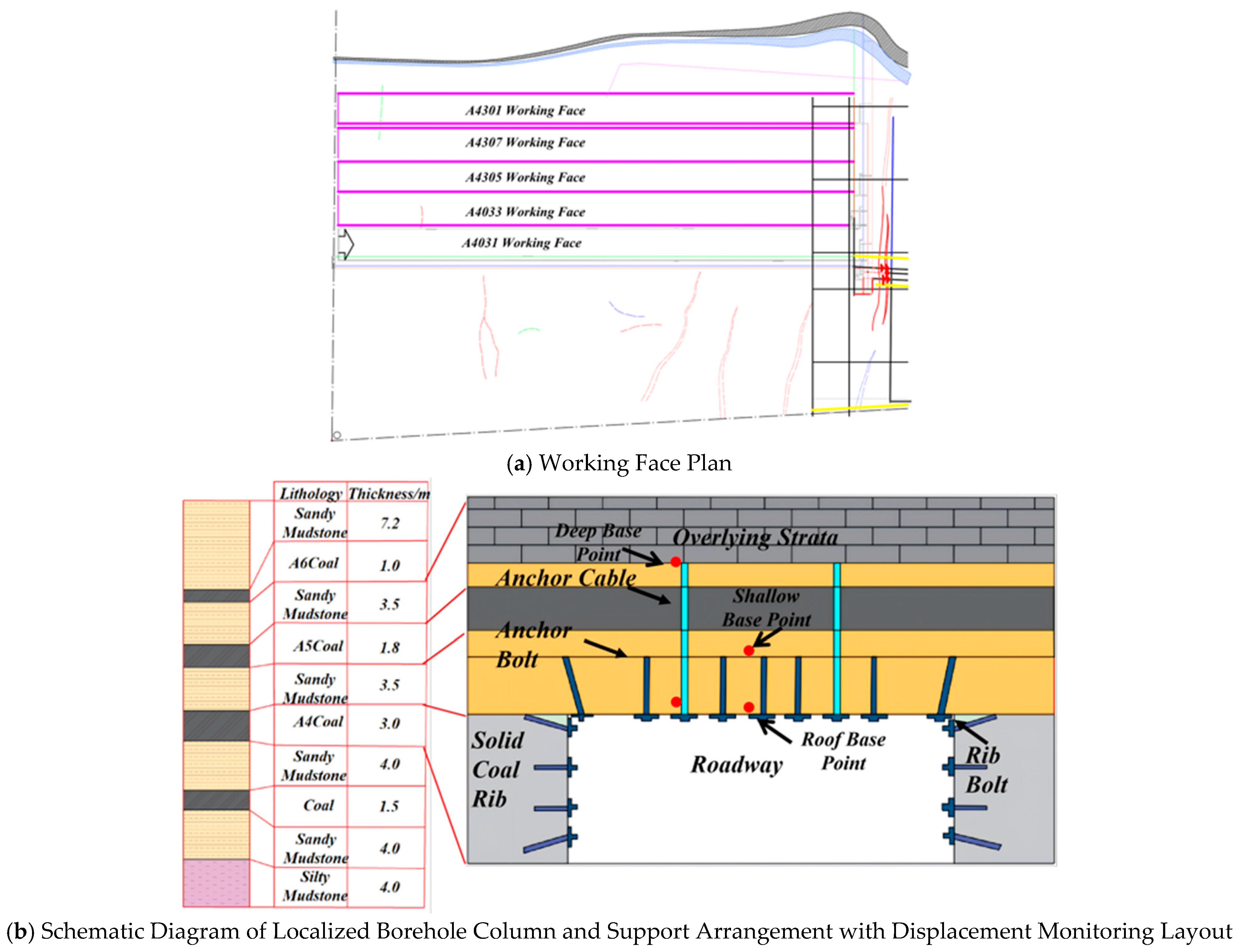
The deposit is located in the Heshitolgai Coalfield of Hubeqxier Mongol Autonomous County, Xinjiang, under the jurisdiction of the Tacheng Prefecture of the Ili Kazakh Autonomous Prefecture. The A4301 longwall roadhead of the initial mining face is situated in the West Third Mining Area, employing a strike-longwall mining technique (Figure 1a). The roadway is laid along the coal seam floor, supported by anchor mesh and cables. It has an excavation width of 5.4 m and height of 2.8 m, surrounded by undisturbed solid coal bodies unaffected by mining activities. The primary exploitable coal seam within the mining area is the A4 seam, with a thickness ranging from 2.46 m to 3.17 m (average 2.60 m). The seam dips at 4° to 7°, making it near-horizontal and sedimentarily stable. The roof and floor consist primarily of sandy mudstone and coal rock. The roadway roof anchors are 22 mm in diameter and 2.4 m long, while the anchor cables are 17.8 mm in diameter and 6.3 m long. Based on actual geological exploration results from a specific borehole at the working face (Figure 1b):
Figure 1.
Overview of the Mining Face.
The roof of the A4 coal seam within a 3.5-m range consists of sandy mudstone. Anchor bolts are anchored in sandy mudstone, meaning that the shallow anchor points are located in sandy mudstone. The roof of the A4 coal seam between 5.3 and 8.8 m consists of the A5 coal seam and sandy mudstone, with the anchor cable passing through the coal seam and anchored in the overlying sandy mudstone, i.e., the deep anchor point is located in sandy mudstone. Neither anchor point could be anchored into stable rock.
3. Calibration of Key Rock Mass Parameters and Damage Characteristics
3.1. Determination and Validation of Rock Mass Parameters in the Trigon Model
In the Trigon model, the rock’s mechanical properties are collectively determined by micro-mechanical parameters, such as the polygonal blocks and their contact interfaces. The elastic modulus of the simulated material is adopted for the blocks, while the deformation of the simulated material is controlled by the normal stiffness and shear stiffness of the block contacts. Gao and Stead [35] investigated the sensitivity relationships between the model’s micro-mechanical parameters and the material’s macro-mechanical parameters, demonstrating that contact cohesion, friction angle, and tensile strength exert significant and effective influences on the material’s overall cohesion, friction angle, and tensile strength. The shear modulus G and bulk modulus K of the Trigon blocks can be converted and determined based on the relationship between the elastic modulus E and Poisson’s ratio ν [36]:
The elastic modulus of the material can be obtained through unconfined uniaxial compression tests. In the numerical model, the elastic modulus of the triangular blocks is kept constant, while the ratio of normal stiffness to shear stiffness is assumed to be a constant value of 0.4. The normal stiffness and shear stiffness of the contact interfaces in the numerical model can be derived from the following equations [35]:
In these equations, ΔZmin represents the minimum edge length of the blocks, while kn and ks denote the normal stiffness and shear stiffness of the contact interfaces, respectively.
The rock parameters obtained from laboratory uniaxial compression and Brazilian splitting tests represent the properties of intact rock blocks, whereas the material parameters used in the numerical simulation models must reflect the properties of the rock mass. To ensure that the simulated rock mass parameters align as closely as possible with the actual physical conditions of the engineering problem, the laboratory-derived intact rock parameters must undergo scaling revision before being implemented in the model. To determine the rock mass parameters, widely recognized empirical formulas are often employed for modification. Specifically, the rock mass elastic modulus can be derived using the following formula [37]:
In these formulas, represents the rock mass elastic modulus, denotes the intact rock elastic modulus, and (Rock Quality Designation)is the rock quality index obtained from in situ borehole core testing. While the sensitivity of RQD to the spacing of discontinuities may be insufficient depending on the selection of threshold values [38], and although certain factors influencing the rock mass deformation modulus are neglected in the derivation, calculating the mean deformation modulus of the rock mass remains highly significant for characterizing the actual engineering conditions.
Additionally, the uniaxial compressive strength of the rock mass can be determined using the following equation [39]:
Among these, represents the maximum principal stress at rock failure, denotes the minimum principal stress at rock failure, signifies the uniaxial strength of rock blocks, while and correspond to Hoek constants. Numerical models typically employ the Mohr–Coulomb linear yield criterion, wherein the maximum and minimum principal stresses satisfy a linear relationship. Therefore, Equation (2) must be fitted into a linear equation:
The y-coordinate value at the intersection of the fitted linear equation with the vertical axis represents the uniaxial strength of the rock mass. The formula for calculating the tensile strength of the rock mass is:
Hoek–Brown [39] recommends a value of ranging from 0.05 to 0.1; in this paper, = 0.1. The modified parameters for each rock mass stratum are shown in Table 1.
Table 1.
Parameters of Stratified Rock Masses.
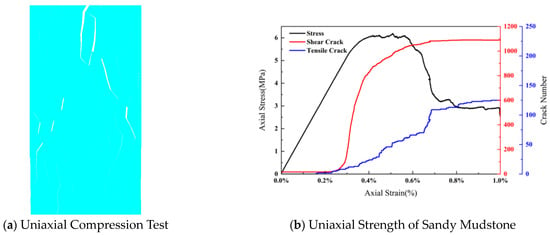
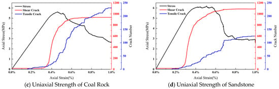
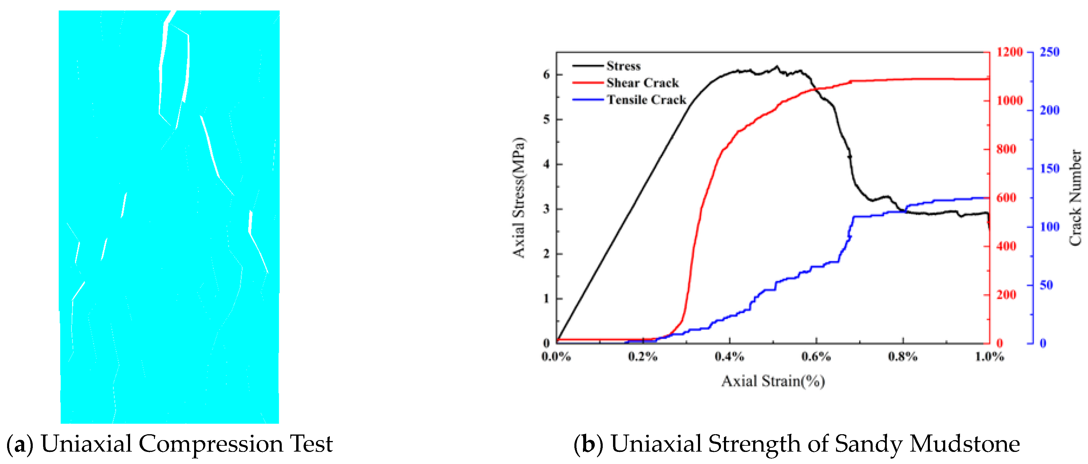
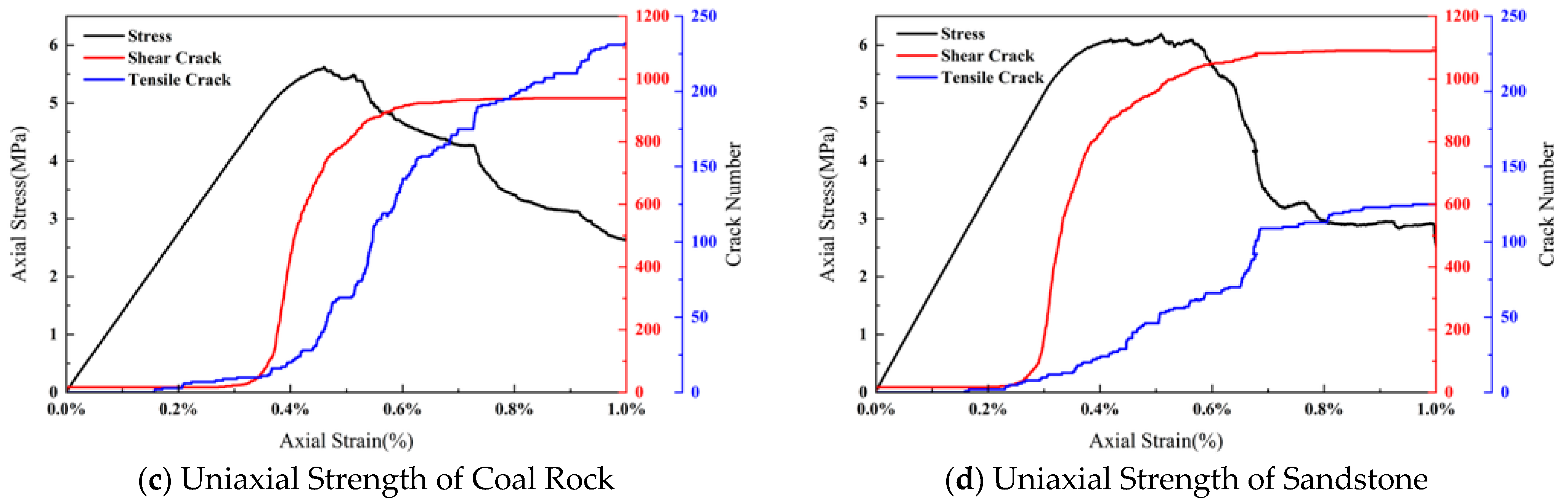
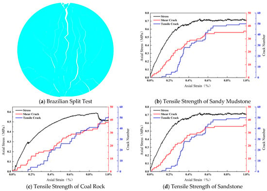
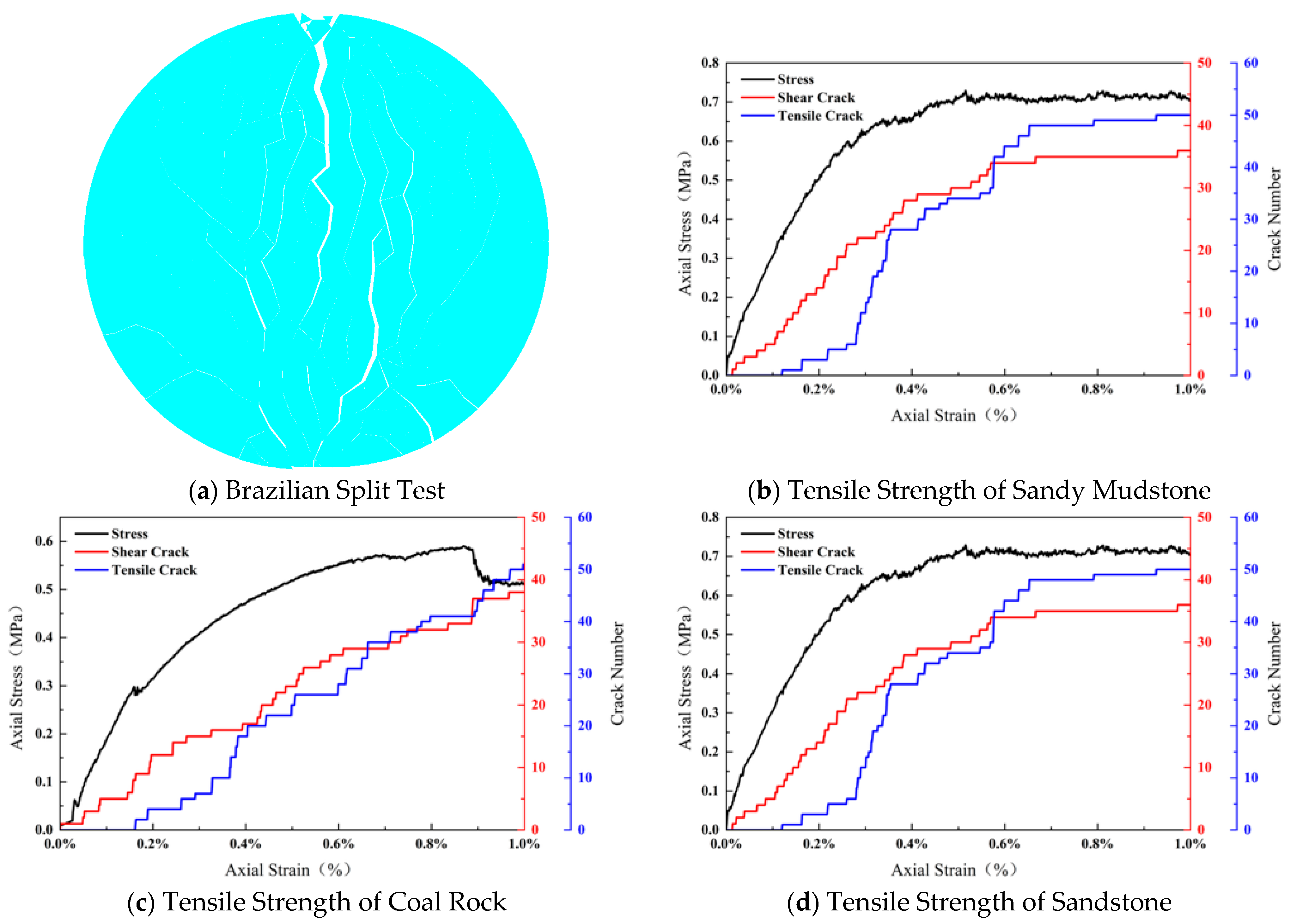
The UDEC Trigon model requires the determination of micro-mechanical parameters, such as polygonal blocks and contact interfaces, for each strata. Based on the aforementioned methodology, four key micro-mechanical parameters were determined: the block elastic modulus (E), contact friction angle (), contact cohesion (), and contact tensile strength (T). The specific micro-mechanical parameters for each rock mass are summarized in Table 2. To verify the rationality of these parameters, multiple uniaxial compression and Brazilian splitting tests were conducted on the determined strata parameters, utilizing a trial-and-error approach for iterative computational adjustments [40]. In the numerical simulations, a rectangular specimen (1 m wide by 2 m high) was used for uniaxial compression, and a circular specimen (2 m in diameter) was used for Brazilian splitting. As illustrated in Figure 2 and Figure 3, under uniaxial compression, the rock mass fractures were dominated by shear cracks, with the number of cracks increasing rapidly when the stress reached 60–80% of the peak strength. In the Brazilian splitting tests, tensile cracks were predominant, and the crack count rose sharply once the stress reached 50–70% of the peak strength.
Table 2.
Micro-Mechanical Parameters for Each Layer in the Trigon Model.
Figure 2.
Uniaxial Compression Stress–Strain Curve of Rock Mass.
Figure 3.
Rock Mass Brazilian Splitting Stress–Strain Curve.
The theoretical values and simulated values for the rock mass elastic modulus, compressive strength, and tensile strength are summarized in Table 3. The error between the simulated values and the theoretical values for each strata was less than 10%, which indicates that the determined micro-mechanical parameters of the rock mass are relatively reasonable. However, the error for certain individual parameters was close to 10%, suggesting that there is still room for fine-tuning and optimization. To minimize the impact of these deviations as much as possible, the rock mass parameters for the subsequent roadway-scale model were further fine-tuned and corrected in combination with field rock pressure monitoring data. This process was conducted to reduce the influence of parameter selection bias on the final simulation results.
Table 3.
Theoretical and Simulated Values of Rock Elastic Modulus and Compressive Strength.
3.2. Characterization of Rock Mass Damage Induced by Mining Activities
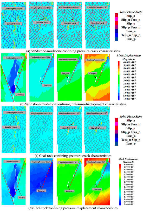
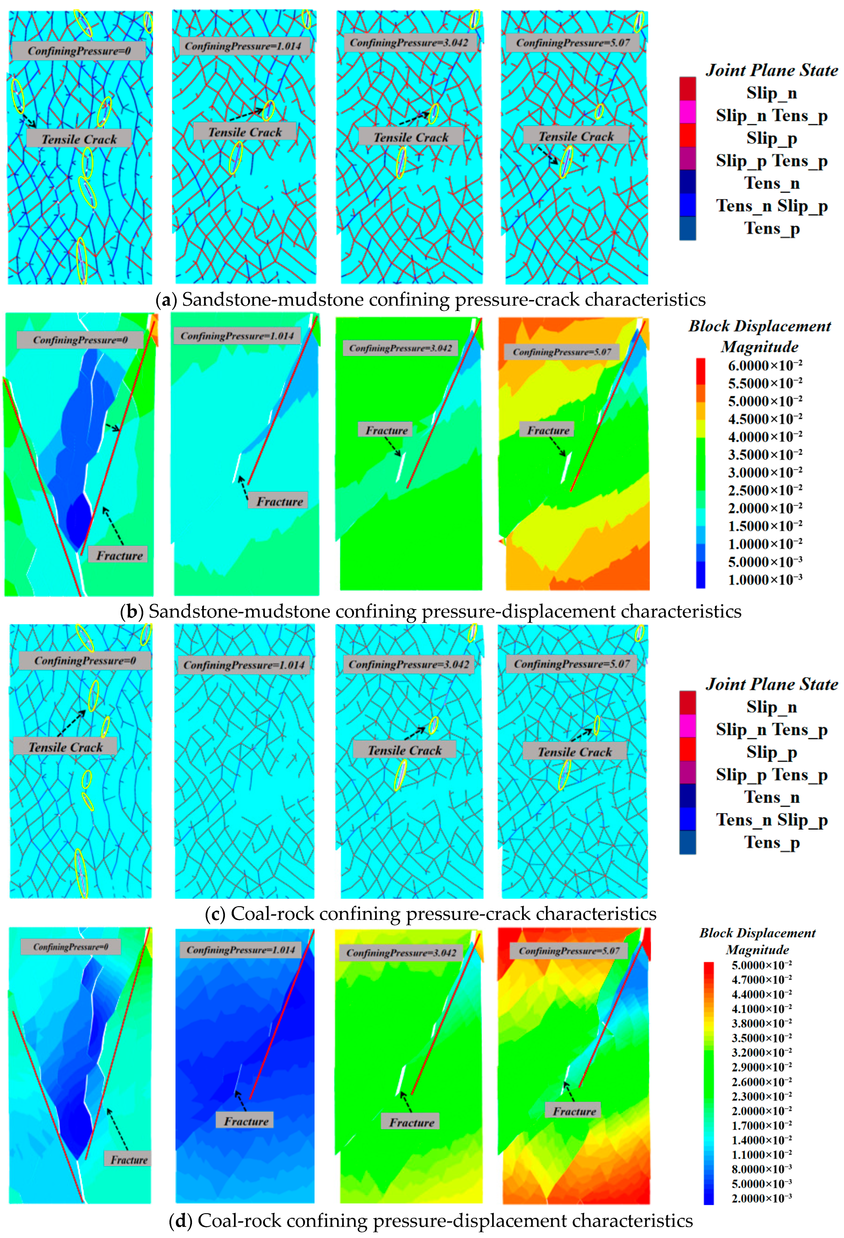
Roadway mining disrupts the original stress equilibrium of rock masses, causing stress redistribution. The surrounding rock in the excavated unloading disturbance zone not only bears axial stresses induced by mining but also experiences confining effects from adjacent rock masses. Mechanically, this is equivalent to confining pressure loading. Therefore, conducting triaxial numerical simulations of rock masses under confining pressure conditions can effectively reproduce the actual mechanical responses and failure mechanisms observed in engineering projects. The roof rock mass of the studied roadway consists of sandy mudstone and coal rock. Using the Trigon numerical model, the damage limit under triaxial compression testing at the rock mass scale was simulated by applying loading in the sequence “confining pressure first, axial pressure second”. As shown in Figure 4, depicting the rock failure process, both sandy mudstone and coal rock exhibited globally penetrating failure characteristics at the termination moment. Tensile fractures formed multiple primary failure zones traversing the rock mass, Tensile stress concentrated at fractures were consistent with Griffith’s failure criterion: initial microcrack tips within the rock induced local tensile stress concentration due to compressive stress. When tensile stress reached the rock’s tensile strength threshold, microcracks propagated along the dominant tensile stress direction and penetrated through. At zero confining pressure, the rock mass exhibits a uniform “V”-shaped fracture, with maximum displacement occurring at the “V” apex. As confining pressure increases, the fracture morphology gradually transitions from ‘V’-shaped to “/” shaped, with maximum displacement distribution becoming more uniform. This indicates that the circumferential constraint of confining pressure enhances the ductile behavior of the rock mass, suppresses sudden crack propagation, and significantly improves its load-bearing capacity.
Figure 4.
Rock Mass Fracture Characteristics under Different Confining Pressures.
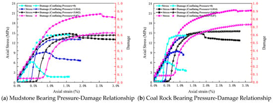
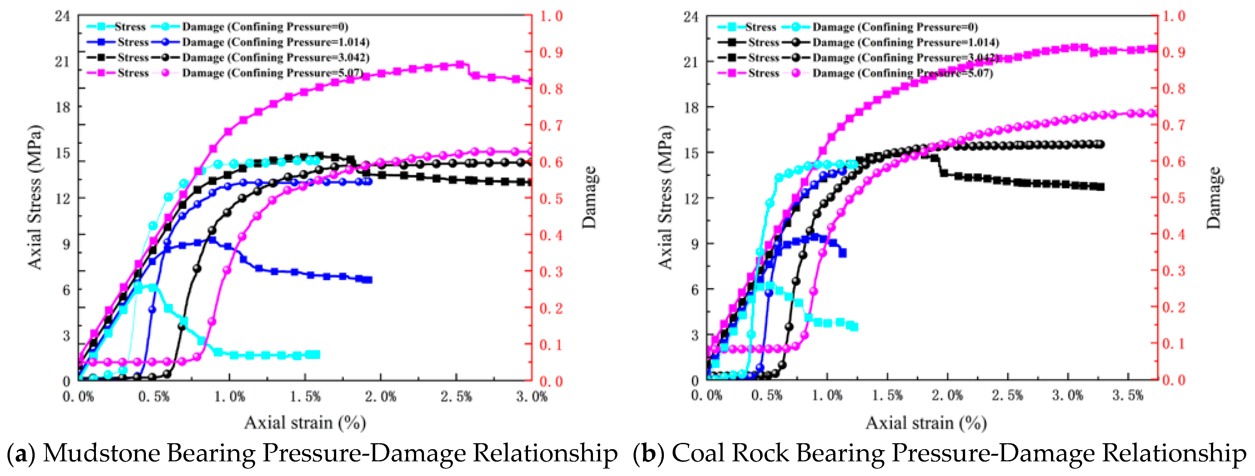
When simulating triaxial compression tests on sandy mudstone and coal rock using the Trigon model, the peak strength exhibited a linear increase trend with increasing confining pressure. The volume strain shifts from compression-dominated to expansion-dominated behavior, demonstrating distinct strain hardening characteristics (Figure 5).
Figure 5.
Critical Values of Rock Mass Damage under Different Confining Pressures.
The damage and failure of brittle rock specimens are closely related to the initiation, propagation, and coalescence of internal micro-fractures. To deeply reveal the damage evolution mechanism of the roadway roof surrounding rock mass, the failure of contacts between blocks in the Trigon numerical model can reflect the development degree of micro-cracks within the surrounding rock. During the process of mining-induced loading, the damage (DI) of the surrounding rock mass is defined as the percentage of the failed block contact length, which includes both shear and tensile failure, relative to the total length of all block contacts [41]. As micro-fractures develop within the surrounding rock mass during mining, the damage effect accumulates, leading to an intensified degree of structural deterioration [42].
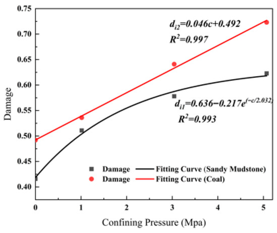
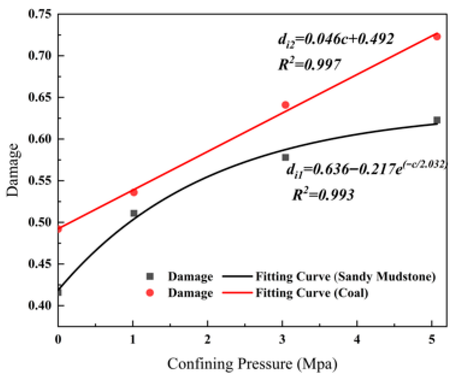
where Ls represents the cumulative tensile crack length at different stages, while Ln denotes the cumulative shear crack length at different stages; L signifies the cumulative crack length, and c represents the confining pressure. The critical damage variable increases when specimen failure occurs: at confining pressures of 0 MPa, 1.014 MPa, 3.042 MPa, and 5.07 MPa, the critical damage variables at failure for mudstone specimens were 0.416, 0.511, 0.578, and 0.623, respectively, while the critical damage variables for coal-rock specimen disintegration were 0.492, 0.536, 0.641, and 0.723, respectively. Analytical equations were derived by fitting the damage critical points of specimens under varying confining pressures (Figure 6). The fitted Equations (10) and (11) for sandy mudstone and coal rock correspond to linear monotonic increasing functions and negative power-law functions, respectively. Based on the functional properties, within this confining pressure range, the damage-promoting effect of confining pressure on coal rock remains stable, while sandy mudstone exhibits rapid damage growth at low confining pressures, with damage slowing as pressure increases. The unloading effect of roadway mining reduces surrounding pressure in shallow zones. Therefore, enhanced support should be prioritized for sandy mudstone and coal seam sections in the shallow regions of the tunnel.
Figure 6.
Fitting Relationship Between Rock Mass Confining Pressure and Damage Critical Value.
4. Criteria for Determining the Critical Value of Roof Separation Based on the Instability of Anchored Support Structures
4.1. Construction of Numerical Models for Roadways
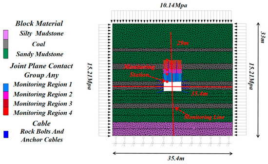
The UDEC Trigon numerical model for the mining roadway of the first working face in the mining district is shown in Figure 7. The dimensions of the model were 35.4 m in width and 33 m in height. The blocks are partitioned using the Voronoi element method, with the maximum allowable edge length set to 0.3 m. After 100 iterations with a rounding coefficient of 0.01, the Trigon elements were further generated. An elastic model was adopted for the block constitutive relationship, while the Mohr–Coulomb model was used for the contact interface constitutive relationship. The numerical model was established based on the dimensions and physical-mechanical parameters of each rock strata shown in Table 2, followed by fine-tuning using field rock pressure monitoring data.
Figure 7.
UDEC Numerical Model.
The numerical boundary conditions were defined as follows: the left and right boundaries are subjected to horizontal fixed constraints and can move freely in the vertical direction, meaning the horizontal displacement at the boundaries is zero. The bottom boundary is a fixed constraint condition, where both the horizontal and vertical displacements of the bottom boundary nodes are zero. Based on the production and geological conditions of the mining area and considering the influence of model boundaries on the numerical simulation, a boundary of approximately 15 m was reserved for the roof, floor, and two ribs of the roadway. Since this paper primarily investigated the failure state of the roadway, the distance between the model boundary and the center of the roadway was set to exceed three times the roadway span [43]. According to the burial depth of the rock strata, a vertical stress of 10.14 MPa was applied to the upper boundary of the model, and the lateral pressure coefficient was set to 1.5. In the UDEC numerical simulation software, cable elements are typically used to simulate anchor cables or rock bolts in support designs. When simulating the sliding deformation of joints controlled by bolts or cables, the cable element itself cannot provide transverse shear force, necessitating the secondary development of the structural elements using the FISH language. A fracture failure criterion for rock bolts and cables, expressed as U(i) greater than or equal to Umax(i), was incorporated into the existing UDEC cable element to satisfy the tensile yield and fracture characteristics of the cable element. In this formula, U(i) represents the length of any unit of the anchor boltor cable, which is detected by the existing UDEC module, while Umax(i) is the limit length of the corresponding unit, which is set manually. In field practice, when the axial direction of an anchor bolt or cable undergoes significant tensile deformation that exceeds the ultimate elongation of the rod body, the rod body fractures. At this moment, the axial force of the rod element at the fracture position instantaneously drops to zero. According to actual pull-out tests, neither the anchor bolt nor the anchor cable experiences de-anchoring; instead, they only undergo tensile rupture and fracture. Therefore, the selected support parameters focus on simulating the tensile failure of the materials. The mechanical parameters of the support units, obtained through field testing and simulation inversion, are summarized in Table 4.
Table 4.
Anchor Bolt and Cable Parameters.
The monitoring of deformation and damage patterns in failure zones prone to severe instability during the coal seam excavation process is a critical objective for conducting simulation experiments. Therefore, displacement monitoring points and damage monitoring zones are established prior to the coal seam excavation. To capture the differences in fracture evolution across various spatial locations, lithologies, and support conditions of the roadway roof surrounding rock, four damage monitoring zones were partitioned in the numerical model according to a spatial gradient of shallow, middle, and deep zones.
Zone 1, located from zero to 2.4 m from the roadway roof, covers the anchor bolt anchorage zone. Its lithology consists of a sandy mudstone section, which serves as the core influence zone for mining-induced stress concentration. Zone 2, located from 2.4 to 3.5 m from the roadway roof, extends from the limit of the anchor bolt anchorage section to the top of this particular rock layer. This layer is situated above the rock bolts and is not constrained by anchor bolt support, functioning as a shallow anchor cable support zone. Zone 3, located from 3.5 to 5.3 m from the roadway roof, is the middle anchor cable support zone, corresponding to the A5 coal seam section in the middle of the roof surrounding rock. Zone 4, located from 5.3 to 7.3 m from the roadway roof, is the anchor cable support limit zone. Its lithology is a sandy mudstone section, which is subjected to a deep stress environment and strong support constraints.
The displacement monitoring points in the model were arranged along survey lines. Observation lines were deployed along the central axes of the roof, floor, and two ribs, respectively, to extract the maximum vertical and lateral displacements in both the shallow and deep areas of the roadway surrounding rock. Simultaneously, monitoring points were arranged at the rock layer boundaries of damage monitoring zones 1 to 4 to extract the roof separation volume of the surrounding rock.
4.2. Simulation Process
Based on the lithology of boreholes in the initial mining face and actual excavation and support conditions, the exploitable coal seam A4 was designated as the roadway excavation zone. Anchor bolts and cables are anchored respectively in the sandy mudstone range above coal seams A4 and A5. The anchor cable anchorage zone constitutes the roadway roof rock mass, with lithology sequentially comprising sandy mudstone, coal rock, and sandy mudstone. During face mining operations, the support pressure within the roadway’s surrounding rock gradually increases due to mining-induced stresses, reaching its maximum value ahead of the working face. By simulating roof separation under various mining stress conditions, which leads to roadway rock mass instability, the ultimate roof separation values within the anchored sections are determined. The maximum values within the bolt anchorage zone and cable anchorage zones are the critical values for shallow and deep roof separation, respectively. The roadway is deemed to have experienced overall instability if any of the following conditions are met: (1) The rock mass damage value within the anchorage range exceeds the critical damage threshold for instability; (2) Large-scale failure of sidewall or roof anchor bolts, or cable rupture.
4.2.1. Development of Microfractures and Characteristics of Surrounding Rock Damage
During the progressive failure process of the surrounding rock mass induced by mining stress loading, the typical micro-damage forms consist of tensile cracks and shear cracks. The former is characterized by splitting failure, which primarily causes surface cracking, spalling, and discretized destruction. The latter typically manifests as sliding failure, which easily leads to block sliding, structural coalescence, and overall instability. To clarify the failure modes of the roadway roof surrounding rock, the fracture fields of the surrounding rock were simulated under conditions where the bearing pressure coefficient K ranges from 1.0 to 2.5. Figure 8 illustrates the evolution characteristics of fractures within the immediate roof of the mining roadway as the bearing pressure coefficient K continuously increases. When K = 1.0, the mining influence is relatively weak; shear cracks are distributed in the shallow part of the immediate roof, while tensile cracks are only sparsely scattered on the surface around the roadway. When K = 1.5, the mining influence strengthens, leading to an increased number of shear cracks in the shallow immediate roof. These cracks are concentrated on the surface and begin to gather locally, while the number of tensile cracks increases slightly. When K = 2.0, the mining influence further intensifies, and the fractures continue to develop into the deeper parts. The loose zone of the surrounding rock nearly covers the anchorage depth of the anchor bolt, and the stability of the roadway roof deteriorates. When K = 2.5, the mining influence reaches its extreme value. The number of fractures within the immediate roof is dense and distributed in a wide range of coalescence. The loose zone of the surrounding rock significantly exceeds the anchorage depth of the anchor bolt. Tensile cracks remain limited to the shallow surface with no significant increase in number, whereas the development of deep shear cracks is prominent and shows a clustered state. Overall, the fracture development of the layered roof exhibits significant asymmetric characteristics. The extent of fracture propagation in the shallow area near the roof surface is markedly higher than that in the deep area, and the damage to the shallow surrounding rock is more severe. Furthermore, influenced by factors such as bedding planes, lithological heterogeneity, and the stiffness mismatch between adjacent layers, non-uniform stress redistribution and differential shear transfer occur within the roof during the process of mining-induced loading and unloading. This leads to distinct differences in the development degree and coalescence range of shear cracks at the left and right shoulder corners of the roadway. Under strong mining conditions, local shear cracks at the shoulder corners are the first to coalesce and develop toward the centerline to form a sliding zone. This asymmetric fracture field further induces differential deformation between the left and right sides of the roof.
Figure 8.
Development Process of Fractures in the Roadway.
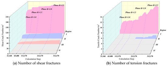
Figure 9 presents the normalized statistics of shear and tensile fracture counts per unit area across four monitoring zones during the mining phase (K = 1.0–2.5). As shown in Figure, shear fractures far outnumber tensile fractures, with shear fractures distributed throughout the entire area, while tensile fractures only emerge sparsely in shallow zones. This indicates that the primary failure mechanism in the monitored roadway section is shear slip failure, with high-value fracture development zones concentrated in the shallow roof area. Simultaneously, both shear and tensile fractures exhibit distinct “regional decline and phased differentiation” characteristics: as the roadway roof rock transitions from shallow to deep zones, the number of fractures decreases progressively from Monitoring Zone 1 to Zone 4. During the intense mining phase (K = 2.5), the peak numbers of shear and tensile fractures per unit area in Zone 1 reached 194.58 and 12.27, respectively, while in monitoring area 2, the peak numbers were 36.03 and 1.51, respectively. In areas 3 and 4, tensile fractures remained constant at zero, with peak shear fracture counts of 24.79 and 1.11, respectively. Overall, fracture development across the monitoring areas exhibited a distinct path of abrupt increase, steady expansion, and gradual accumulation.
Figure 9.
Evolutionary Trend of Fracture Counts in the Roof Rock Monitoring Area.
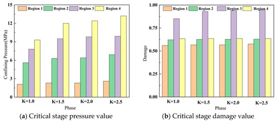
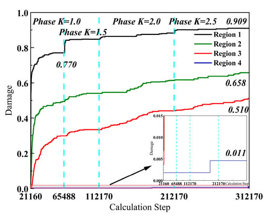
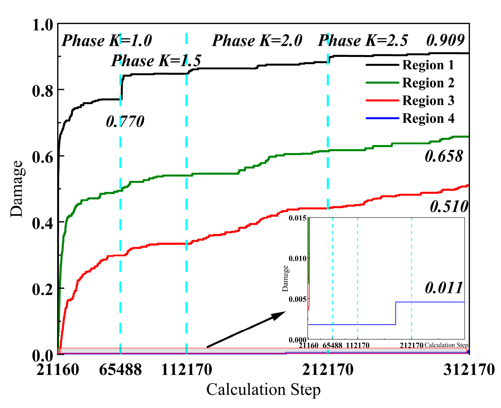
Extensive connectivity of fissures in the roof rock mass of roadways forms continuous failure zones, leading to roof collapse. Quantifying fissure lengths yields damage values to determine whether failure thresholds are reached. Key stage pressure variation data from the monitored model regions were extracted (Figure 10a). Based on lithological differences, these values were substituted into Equations (10) and (11) to derive the rock mass damage thresholds (Figure 10b). Combined with the progressive damage timeline shown in Figure 11 for four monitoring zones in the roadway roof rock mass, regional stability can be assessed by comparing damage values between the roadway surrounding rock models and the rock mass models. Since the rock mass–damage relationship described in Figure 4, Figure 5 and Figure 6 and the sequential damage evolution laws of the roadway roof surrounding rock revealed in Figure 11 were both conducted at the rock mass scale, it is feasible to assess the stability of the specific regions by such comparison of the damage values.
Figure 10.
Bearing Pressure and Damage Values at Key Stages in the Monitoring Area.
Figure 11.
Time-Series Damage Patterns in the Monitoring Area.
The details are as follows: Zone 1 rapidly escalated its damage value to 0.770 during the initial mining phase (K = 1.0), exceeding the sandy mudstone rock mass damage threshold of 0.559. This indicates that Zone 1’s rock mass reached a fractured state first under disturbance. In Zone 2, damage values stabilized at 0.658 during the final mining phase, with rock mass degradation progressively exceeding the failure threshold. Deep roof in Monitoring Zone 3 experienced failure but remained below the coal-rock mass damage threshold, while Zone 4 exhibited stable, controlled damage at extremely low levels.
4.2.2. Failure Conditions of the Support System
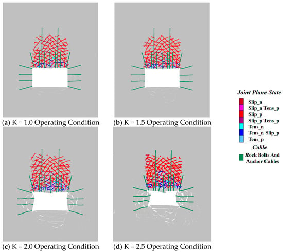
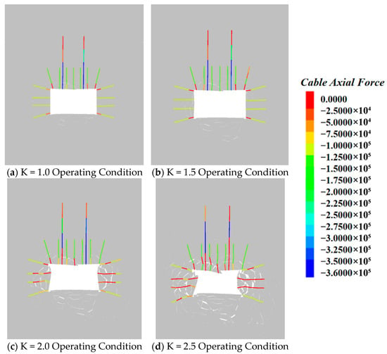
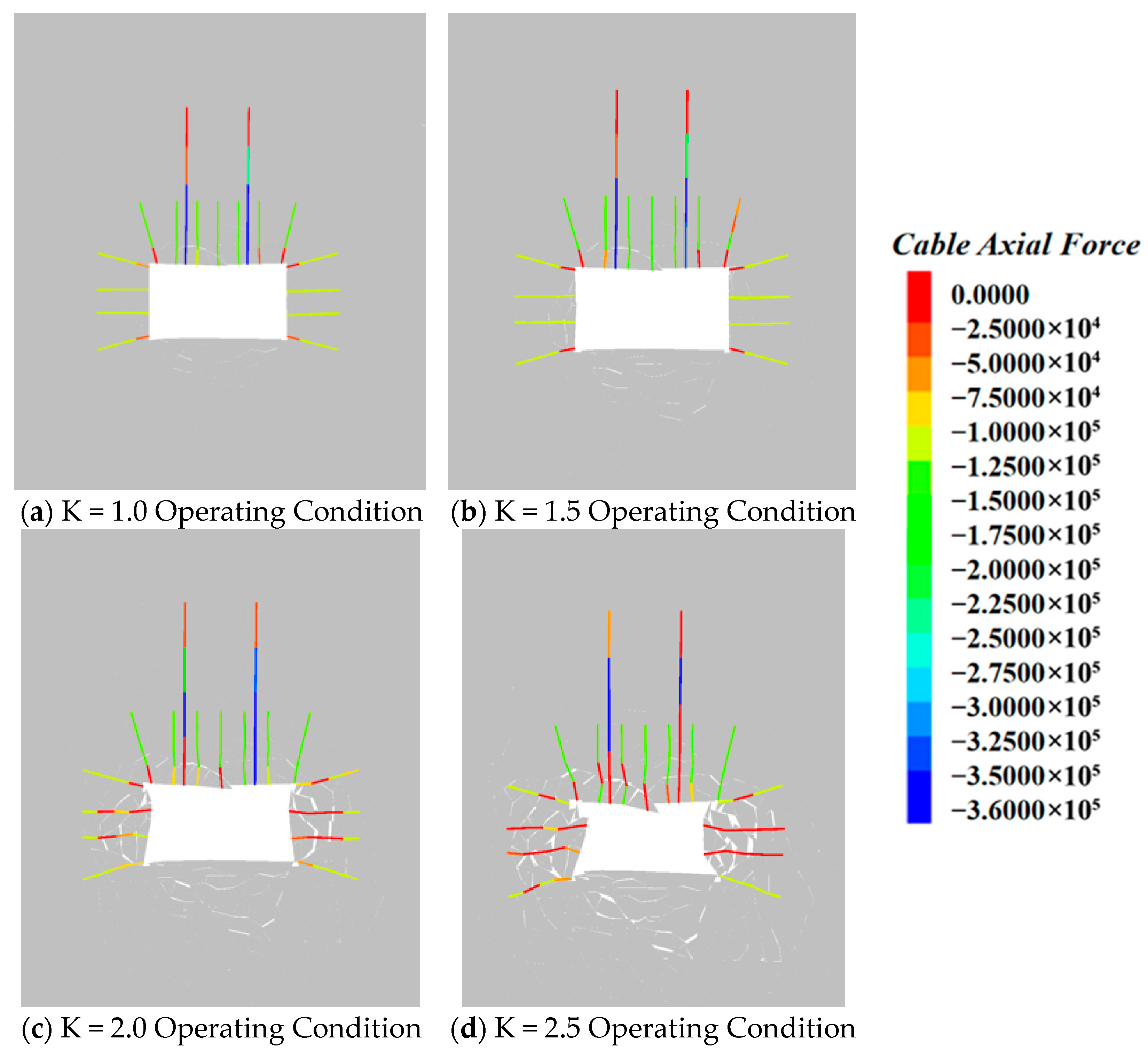
The fracture characteristics of support materials—anchor bolts and anchor cables—under stress response can also serve as critical indicators for the critical state of roof separation in roadways. As shown in Figure 12, the axial tensile stress distribution of anchor bolts and anchor cables in the cable unit revealed the following. At K = 1.0, most support material units exhibited bending yield, while the bottom end of anchor cables underwent tensile yield, with failure occurring at the base of the top anchor rods on both sides and the top section of the cable. At K = 1.5–2.0, most anchor rod elements in the roof and sidewalls exhibited pronounced angular plastic twists, with a significant increase in failed sidewall anchor rods at the roadway shoulder angle. At K = 2.5, the two right-side rib bolts completely failed, with cracks observed at both the bottom and middle sections of the roof bolts, and widespread failure of the cable. Deformation characteristics of support materials in Monitoring Zones 1–4 indicate that as the surrounding rock deformation intensifies, support constraint in the anchoring section diminishes. At K = 1.5, anchor rods exhibited clear fractures while cable segments remained largely intact with minor breaks; at K = 2.0, the ultimate anchoring section of cables failed.
Figure 12.
Failure Patterns of Roadway Support Systems.
4.2.3. Evolutionary Patterns of Roadway Surrounding Rock Displacement
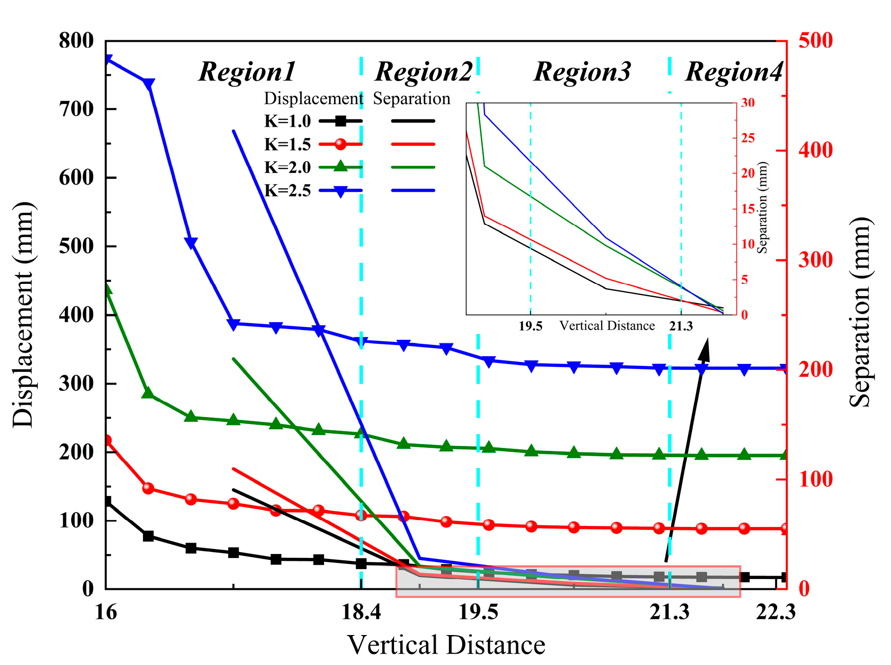
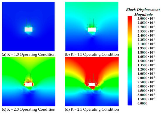
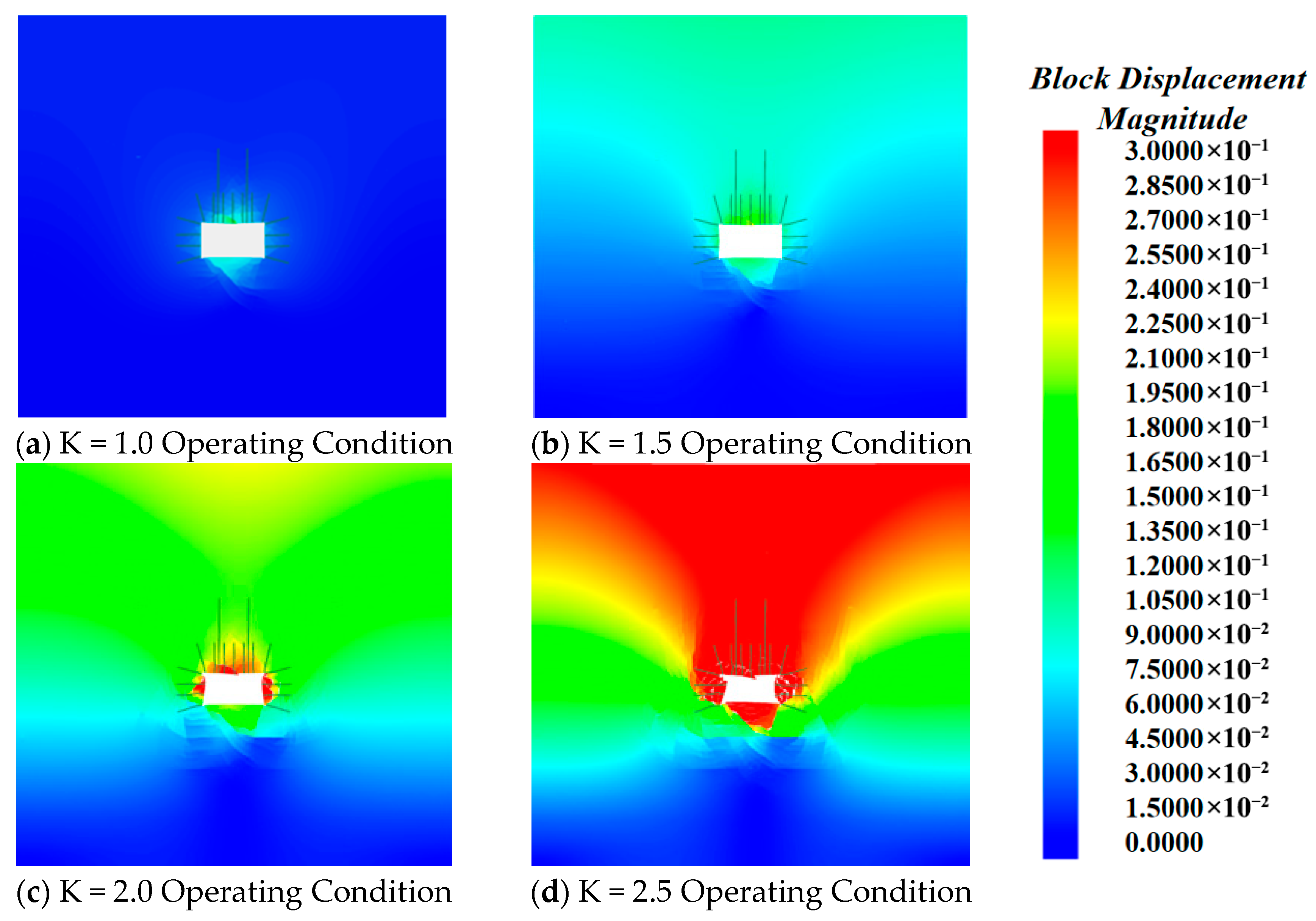
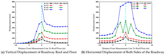
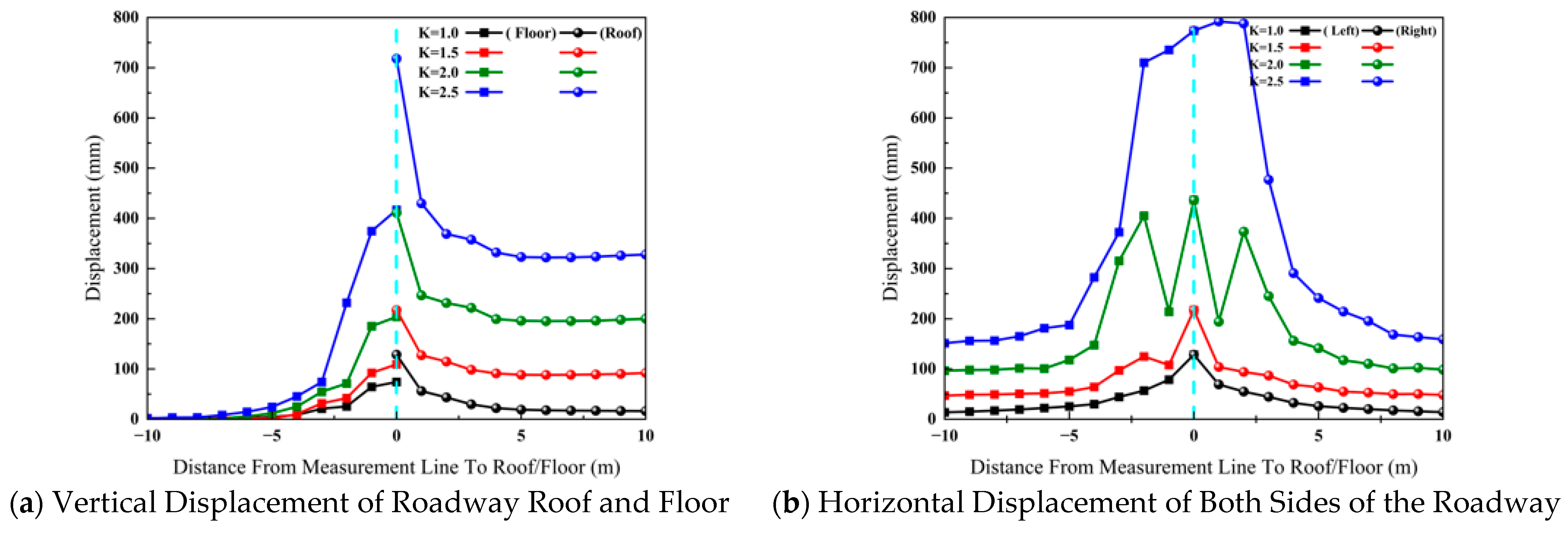
Under mining stress, the evolution of the displacement field in the roadway surrounding rock provides a direct representation of the rock mechanical response, reflecting the development state of the roof separation and the stability of the surrounding rock. The distribution pattern of the maximum displacement contour map for the roadway surrounding rock is shown in Figure 13. As the support pressure coefficient K increases, the overall displacement amplitude continues to grow, with the maximum deformation occurring in the near-surface regions of the roadway roof and both sidewalls. Extracting displacement profiles from survey lines revealed the evolution curve of roadway surrounding rock settlement displacement, as shown in Figure 14a,b. Significant differences exist in the vertical displacement of the roof and floor surrounding rock, while the displacement of the two sidewalls tends to be mirror-image symmetrical. When K = 1.0, roadway deformation was minimal, with roof and floor displacements symmetrically distributed along the roadway center line in the shallow layer. Deformation values for the roof, floor, and both sidewalls were 128 mm, 74 mm, and 128 mm, respectively. Following mining-induced pressure increase, the roadway roof and floor concave inward, the contour lines of rock mass displacement expand, and the gradient difference becomes significant, resulting in a substantial increase in overall deformation. Regarding displacement increments, as K increased from 1.5 to 2.5, the maximum roof subsidence rose from 217 mm to 718 mm, the floor heave increased from 109 mm to 417 mm, and the sidewall convergence increased from 217 mm to 713 mm. The displacement increments were 501 mm, 308 mm, and 496 mm, respectively. The roof exhibited the highest subsidence amplitude and produced significant macroscopic sliding deformation, indicating that the roadway rock mass had entered a stage of overall instability and strong deformation.
Figure 13.
Maximum Displacement Contour Map of the Tunnel.
Figure 14.
Evolutionary Patterns of Surrounding Rock Displacement in the Roadway.
4.3. Determination of Critical Values for Roof Rock Displacement
Combining the quantitative analysis of the roadway fracture field, displacement field, and support system mentioned previously, and classifying based on the horizon relationships between the surrounding rock and support materials, a dual-criterion model is provided. This model integrates the damage degree of surrounding rock and the fracture characteristics of support materials to comprehensively characterize the critical roof separation. The specific logic is as follows.
When the horizon of the support material is higher than that of the surrounding rock, if the damage to the surrounding rock within the anchorage range exceeds the critical threshold but the upper support material has not fractured, a net-bag structure may exist where the rock layer has collapsed but the support system still provides tensioned support. Conversely, if the support material fractures but the surrounding rock damage has not reached the critical value, it may indicate insufficient support strength. Therefore, instability cannot be determined in either of these two cases. When the horizon of the surrounding rock is higher than or equal to that of the support material, the instability of the roadway roof follows a pattern of progressive failure from shallow to deep zones. If the damage threshold of the upper rock layer exceeds the critical value, it represents that the overlying strata have collapsed, and the subsequent settlement of the overlying strata indicates the structural bearing failure of the underlying rock layers. Regardless of the horizon relationship, if the surrounding rock damage exceeds the critical threshold and the support material fractures simultaneously, it signifies that the surrounding rock has collapsed while losing the constraints provided by the support system. Therefore, these two conditions are used to determine instability.
Following the aforementioned discrimination logic, the stability of the four monitoring zones of the roadway roof was assessed in sequence: During the K = 1.0 stage, in the anchor bolt anchorage zone where the rock horizon is equal to the bolt support range, the rock bolts will settle along with the surrounding rock when the damage value exceeds the rock mass damage threshold. At this point, the shallow region of the roadway roof, designated as Monitoring Zone 1, is considered unstable. During the K = 1.5 stage, the rock bolts at the ribs and roof fail extensively, and the damage to the surrounding rock in the shallow region exceeds the threshold. This indicates overall instability of the roadway, including the failure of the deep roof regions designated as Monitoring Zones 2, 3, and 4.
The roof separation volume can be regarded as the deflection difference caused by the uncoordinated deformation between rock layers. According to the rock layer settlement displacement values in the roadway roof monitoring zones shown in Figure 16, the separation volume increases gradually as mining stress is released. The maximum separation volumes in Zones 1 to 4 exhibit a pattern of gradient-based rapid reduction. This indicates that under the induction of mining stress, the surrounding rock near the surface of the roadway is more prone to interlayer sliding. The coordinated control by deep-level anchor cables effectively suppresses the expansion of separation, significantly weakening the deformation of the surrounding rock and maintaining the separation volume at a low level. The lateral constraint effect of the solid coal ribs on both sides of the roadway causes the stress release to be more gradual compared to the central position.
It should be noted that in practical engineering applications, the shallow separation volume typically refers to the distance from the shallow base point to the roof base point, while the deep separation volume is the distance from the deep base point to the roof base point. Therefore, in the numerical simulation, the critical value for shallow separation was selected as the interlayer displacement of Zone 1 during the K = 1.0 stage, and the critical value for deep separation was selected as the sum of the interlayer displacements of Zones 1 to 4 during the K = 1.5 stage. The calculated values were 90.7 mm and 129.03 mm, respectively, as shown in Figure 15. Considering that the RQD of real heterogeneous strata and variable working conditions is a range, which affects the reduced rock mass parameter values in the model, and that the block particles and mesh sizes of the UDEC model may also cause computational deviations [44], a tolerance of 5% was applied. Consequently, the critical values for shallow and deep separation were determined to be 90.7 plus or minus 4.54 mm and 129.03 plus or minus 6.45 mm, respectively.
Figure 15.
Distribution Patterns of Roadway Displacement Field and Displacement Layers.
5. Actual Measurement of Roof Displacement
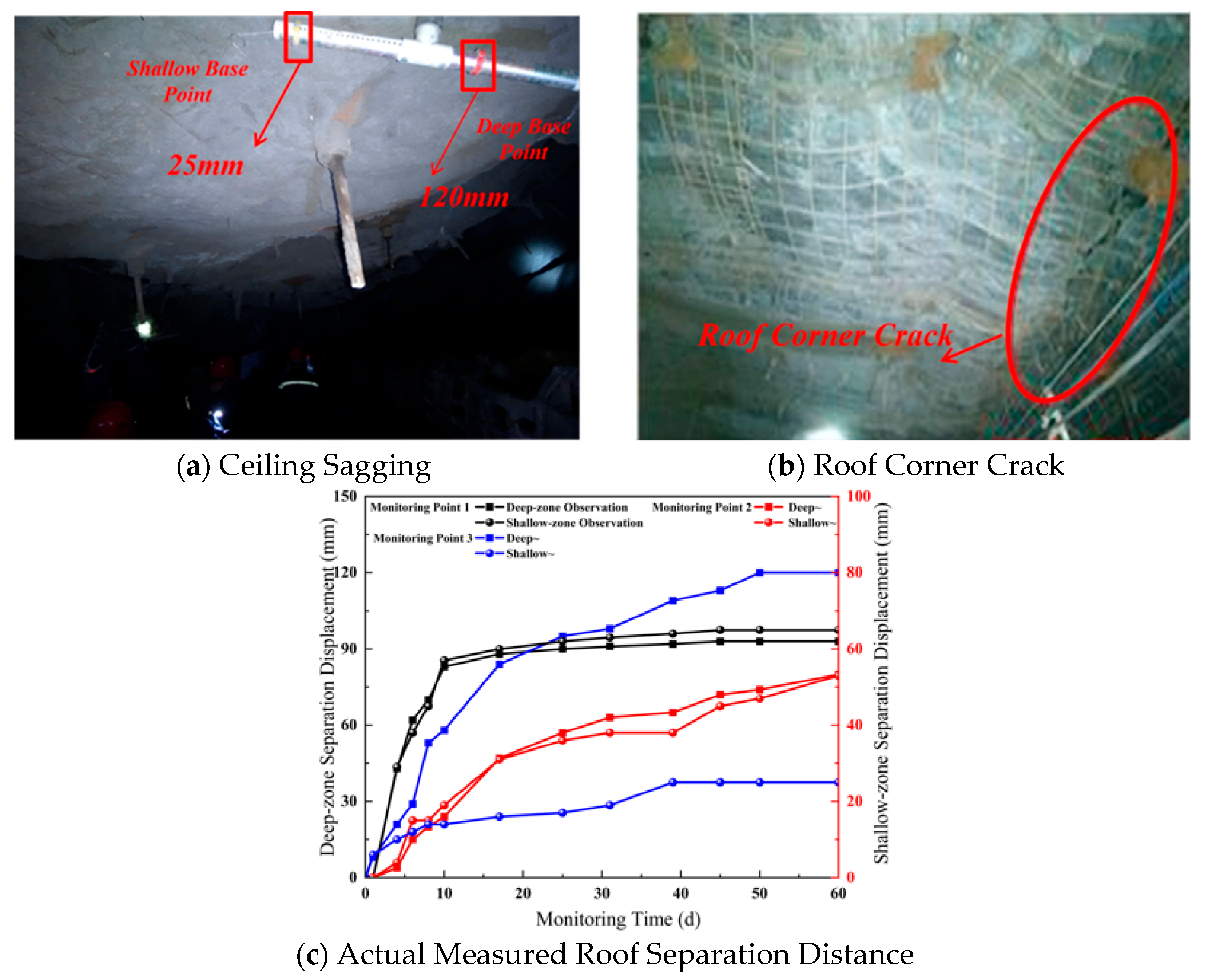
Cracks appeared in several locations along the transport roadway of the A4301 working face, and the roadway roof exhibited significant subsidence, as shown in Figure 16a. As illustrated in Figure 16b, a crack oriented along the direction of the roadway was observed at the roof corner, with a crack length of approximately 7.5 m and a crack width of approximately 30 mm. To observe the separation of the roadway roof, three monitoring stations were arranged closely following the heading face during the excavation of the A4301 transport roadway. The spacing between the stations was 100 m, and a roof separation monitoring point was installed within each station, with the monitoring period covering a complete mining cycle.
As can be seen from Figure 16c, the separation deformation of the roadway roof increased progressively, with the deep separation volume being greater than the shallow separation volume. If no measures are taken, there is a tendency for continued deformation and failure. The deep roof separation volumes at Monitoring Points 1 to 3 were 93 mm, 80 mm, and 120 mm, respectively, while the shallow separation volumes were 65 mm, 53 mm, and 25 mm, respectively. At Monitoring Point 3, when the deep separation volume reached 120 mm, the roof experienced instability. This result exhibited an error of approximately 7% compared to the simulated critical value of 129.03 mm for deep separation. This is fundamentally consistent with the rock mechanics calculation and safety requirements, verifying the engineering applicability of the methodology proposed in this paper.
Figure 16.
Measured Subsidence and Displacement of the Roadway Roof.
6. Conclusions
- (1)
- Inversion of field conditions revealed the triaxial damage patterns of rock masses under confining pressure. Sand-rich mudstone exhibited rapid damage growth at low confining pressures, which slowed under high confining pressures, indicating heightened sensitivity to low-pressure environments caused by shallow mining unloading. In contrast, coal-bearing rock showed stable damage accumulation rates with increasing confining pressure, suggesting that differential confining pressure regulation is the key factor triggering deformation mismatch in interbedded sections of differing lithologies.
- (2)
- Through UDEC discrete element numerical simulation, the instability state of the roof rock in the monitored roadway was analyzed by zone. Four failure types were identified across the monitoring areas, revealing the evolution pattern of stratiform roof failure in the mine’s roadways. Under mining stresses, damage to roof rock fractures exhibited a gradient distribution characterized by intense damage near the surface and gradual damage at depth. Shear slip dominated the failure mode, with anchor rod (cable) failures concentrated in the shallow anchorage zone. This indicates that the shallow roof zone constitutes the core influence zone requiring priority reinforcement. The differential shear transfer within the roof surrounding rock leads to the gradual coalescence of cracks at the left and right shoulder corners of the roadway under strong mining conditions. These cracks develop toward the centerline to form a sliding zone. Furthermore, the resulting asymmetric fracture field further induces differential deformation between the left and right sides of the roof.
- (3)
- To address the challenges in deducing and measuring the critical values of roof separation in mining roadways within the weakly cemented coal-bearing strata of this mine, this paper proposes a determination method for characterizing these critical values based on a dual-criterion approach that integrates support material fracture and surrounding rock damage-induced instability. Compared to traditional theoretical calculation methods that rely on a single criterion, such as the maximum deflection of an anchored rock beam or the ultimate elongation of support materials, the proposed method utilizes discrete element simulation to employ both the damage degree of surrounding rock and the fracture characteristics of support materials as dual criteria. This approach fully reflects the mechanical essence of the coaxial bearing between the surrounding rock and the support system within an anchored bearing structure. Through numerical computation, the critical values for shallow and deep separation at this mine were determined to be 90.7 mm and 129.03 mm, respectively. These results are very close to the actual separation volumes observed during periods of severe roof subsidence, indicating that the proposed methodology is reasonable and effective.
- (4)
- Overall, this research still possesses certain limitations. The fitting relationship between the confining pressure and the damage variable proposed in this paper was obtained through quasi-static triaxial simulation of the rock mass and does not account for the influences of complex rock loading stress paths, moisture content, or rheological effects. Therefore, the damage threshold proposed in this paper should be interpreted as an engineering reference value under conditions of quasi-static stress redistribution rather than a comprehensive dynamic failure criterion. Furthermore, the numerical model calculations represent a result of appropriate simplifications of complex field geological structures and joint distributions, thereby entailing a certain tolerance range. The proposed dual-criterion method for the critical values of roof separation was established based on the specific engineering background of this mine and has not yet undergone extensive validation under varying geological conditions or excavation and support configurations. The universality of these research findings still requires further support from additional field case studies and experimental data.
Author Contributions
Conceptualization, G.L., and Z.L.; methodology, G.L. and Z.L.; software, Z.L.; validation, Z.L., H.W., H.F., K.Z. and G.Z.; formal analysis, Z.L.; investigation, P.G.; resources, P.G. and G.L.; data curation, Z.L.; writing—original draft preparation, Z.L. and G.L.; writing—review and editing, G.L. and H.L.; visualization, Z.L.; supervision, P.G.; project administration, G.L.; funding acquisition, H.L. All authors have read and agreed to the published version of the manuscript.
Funding
This research was supported by the Key Research and Development Projects of Xinjiang Uygur Autonomous Region, China (2025B03001-1, 2023B01010, 2024B03017), National Natural Science Foundation of China (52464008), and Postgraduate Research and Practice Innovation Program of Xinjiang Uygur Autonomous Region, China (XJ2026G094).
Data Availability Statement
The original contributions presented in this study are included in the article. Further inquiries can be directed to the corresponding author.
Conflicts of Interest
Authors Zhiqiang Liu, Guodong Li, Honglin Liu, Hongzhi Wang, Haotian Fu, Kangfei Zhang, and Guodong Zeng were employed by Xinjiang University, Pingtao Gao was employed by the Xu Mine Group Xinjiang Hongshan Energy Co., Ltd. The remaining authors declare that the research was conducted in the absence of any commercial or financial relationships that could be construed as potential conflicts of interest.
References
- Sun, L.; Ji, H.; Yang, B. Physical and mechanical characteristic of rocks with weakly cemented strata in Western representative mining area. J. China Coal Soc. 2019, 44, 866–874. [Google Scholar] [CrossRef]
- Song, Z.; Ji, H.; Zeng, P.; Sun, L.H.; Tan, J. Phase-like transition characteristics of uniaxial compression failure of weakly cemented coarse-grained sandstone in western China. J. Min. Saf. Eng. 2020, 37, 1027–1036. [Google Scholar]
- Zhang, W.; Zheng, X.; Bai, J.; Wang, L.; Chen, J.; Ma, X.; Li, J. Present situation and control countermeasures of roof disaster of weakly cemented roadway in Xinjiang Mining Area. Saf. Coal Mines 2023, 54, 163–169. [Google Scholar]
- Huang, Y.; Pan, X.; Lin, Z. Deformation failure law and control countermeasure of deep buried weakly cemented soft rock roadway. Saf. Coal Mines 2022, 53, 210–218. [Google Scholar]
- Jv, W. Monitoring technology for rock bolting engineering. J. China Coal Soc. 2000, 25, 58–61. [Google Scholar] [CrossRef]
- Yao, B.; Zhou, Y. Roof separation analysis and monitoring techniques in roadways. Coal Min. Technol. 2004, 41–42+51. [Google Scholar]
- Kong, H.; Ma, N.; Wang, M.; Zhang, C. Controlled Stability of Rock Bolting Roadways Based on Roof Abscission Layer Monitor. China Saf. Sci. J. 2002, 58–61+86. [Google Scholar] [CrossRef]
- Wang, J. Analysis on mechanism and effect of rock bolts and cables in gate road with coal seam as roof. J. China Coal Soc. 2012, 37, 1–7. [Google Scholar]
- Kang, H. Sixty years development and prospects of rock bolting technology for underground coal mine roadways in China. J. China Univ. Min. Technol. 2016, 45, 1071–1081. [Google Scholar]
- Meng, Q.; Han, L.; Sun, J.; Min, F.; Feng, W.; Zhou, X. Experimental study on the bolt-cable combined sup-porting technology for the extraction roadways in weakly cemented strata. Int. J. Min. Sci. Technol. 2015, 25, 113–119. [Google Scholar] [CrossRef] [Scilit]
- Hou, C. Key technologies for surrounding rock control in deep roadway. J. China Univ. Min. Technol. 2017, 46, 970–978. [Google Scholar]
- Zhang, G.H.; Liang, B.; Zhang, H.W.; Zhang, X.F. Analysis of the roof separation in mining roadway and technical parameters determination of bolt combined supporting. J. Chongqing Univ. 2010, 33, 135–140. [Google Scholar]
- Liu, C.; Guo, Y. Analysis on roof bedding separation critical value of coal mining gallery supported with bolts (cables). Rock Soil Mech. 2003, 231–234. [Google Scholar] [CrossRef]
- Wang, L.; Tan, X.; Zang, C. Mechanical Model of Roadway Roof Separation Model and Judgment of Surrounding Rock Instability. Coal Eng. 2015, 47, 95–98. [Google Scholar]
- Jing, L.-W.; Peng, S.-C.; Yan, Y.; Li, S.; Li, X.; Jing, W. Study on coal seam roof failure based on stress potential function of laminated beams. Coal Eng. 2022, 54, 84–89. [Google Scholar]
- Zhou, M. Limit value confirmation of roadway roof separation and safety evaluation of Xinwen mining area. Coal Min. Technol. 2008, 13, 86–88. [Google Scholar]
- Hao, D.; Cui, Q.; He, J.; Guo, X.; Cheng, P. Deformation characteristics and separation monitoring of layered roof roadway supported with bolts and cables. J. China Coal Soc. 2017, 42, 43–50. [Google Scholar] [CrossRef]
- Hebblewhite, B.K.; Lu, T. Geomechanical behaviour of laminated, weak coal mine roof strata and the implications for a ground reinforcement strategy. Int. J. Rock Mech. Min. Sci. 2004, 41, 147–157. [Google Scholar] [CrossRef] [Scilit]
- Wang, Y.; Yuan, H.; Gao, M.; Li, M.; Sun, J. Fracture law of different overlying strata in mining of protective seam under close distance coal seam. Energy Sci. Eng. 2023, 11, 1336–1348. [Google Scholar] [CrossRef] [Scilit]
- Wang, X.; Zhang, Y.; Zhang, Q.; Wei, Y.; Liu, W.; Jiang, T. Space-time evolution characteristics of deformation and failure of surrounding rock in deep soft rock roadway. Sustainability 2022, 14, 12587. [Google Scholar] [CrossRef] [Scilit]
- Liu, H.; Wu, X.; Hao, Z.; Zhao, X.; Guo, X. Evolution law and stability control of plastic zones of retained entry of working face with double roadways layout. J. Min. Saf. Eng. 2017, 34, 689. [Google Scholar]
- Bai, Q.; Tu, S. Numerical observations of the failure of a laminated and jointed roof and the effective of different support schemes: A case study. Environ. Earth Sci. 2020, 79, 202. [Google Scholar] [CrossRef] [Scilit]
- Zhao, Q.; Zhang, N.; Peng, R.; Li, G.; Zhang, K.; Han, C.; Shi, J. Similarity simulation experimental study on abrupt collapseof roof separation in large cross-section argillaceous roadway. J. Min. Saf. Eng. 2018, 35, 1107–1114. [Google Scholar] [CrossRef]
- Zhang, W.-J.; Zhang, H.-W.; Yu, S.-G. Study on the monitor method of roof separation in bolter support roadway. J. Liaoning Tech. Univ. 2002, 421–424. [Google Scholar]
- Jv, W.; Liu, D. Determination method for separating layer limit of mine roadway roof supported with roof bolts. Coal Sci. Technol. 2001, 27–29. [Google Scholar] [CrossRef]
- Tang, J.; Deng, Y.; Tu, X.; Hu, H. Analysis of roof separation in gob-side entry retaining combined support with bolting wire mesh. J. China Coal Soc. 2010, 35, 1827–1831. [Google Scholar] [CrossRef]
- Lin, J.; Ma, K.; Yang, J.; Fan, M.J. Determination method for critical value of roof separation limited by anchored bolt supporting system. Coal Ming Technol. 2014, 19, 47–50. [Google Scholar]
- Tan, Y.L.; Yu, F.H.; Chen, L. A new approach for predicting bedding separation of roof strata in underground coalmines. Int. J. Rock Mech. Min. Sci. 2013, 61, 183–188. [Google Scholar] [CrossRef] [Scilit]
- Yan, H.; Zhang, J.; Wang, S.; Cao, Y. Simulation study on key influencing factors to the roof abscission of the roadway with extra-thick coal seam. J. Min. Saf. Eng. 2014, 31, 681–686. [Google Scholar] [CrossRef]
- Zhang, Y. Study on Bearing Characteristic of Composite Bolt-Rock Bearing Structure and Its Application in Roadway Bolting Design; China University of Mining & Technology: Beijing, China, 2013. [Google Scholar]
- Yang, S.-Q.; Li, H.; Du, S.-G.; Yong, R.; Wang, S.-S.; Tian, W.-L.; Hu, Y.-J.; Niu, Y. Experiment and Peridynamics Simulation on Failure Mechanical Behavior of Cylindrical Sandstone Containing Two Persisting Fissures Under Conventional Triaxial Compression. Rock Mech. Rock Eng. 2024, 58, 3129–3157. [Google Scholar] [CrossRef] [Scilit]
- Zhao, Y.-C.; Yang, T.-H.; Qin, T.; Wang, H. Effects of Confining Pressure Paths on Strength and Deformation of Calcareous Argillaceous Cemmented Sandstones. J. Northeast. Univ. Nat. Sci. 2018, 39, 254–259. [Google Scholar] [CrossRef]
- Xie, H.P.; Zhou, H.W.; Liu, J.F.; Xue, D.J. Mining-induced mechanical behavior in coal seams under different mining layouts. J. China Coal Soc. 2011, 36, 1067–1074. [Google Scholar]
- Teng, T.; Wang, Y.; Chen, Y.; Li, Y.; Liu, X. Permeability and Energy Evolution of Coal under Unloading Confining Pressure. Int. J. Geomech. 2026, 26, 04025341. [Google Scholar] [CrossRef] [Scilit]
- Gao, F.; Stead, D. The application of a modified Voronoi logic to brittle fracture modelling at the laboratory and field scale. Int. J. Rock Mech. Min. Sci. 2014, 68, 1–14. [Google Scholar] [CrossRef] [Scilit]
- Kazerani, T.; Zhao, J. Micromechanical parameters in bonded particle method for modelling of brittle material failure. Int. J. Numer. Anal. Methods Geomech. 2010, 34, 1877–1995. [Google Scholar] [CrossRef] [Scilit]
- Zhang, L.; Einstein, H.H. Using RQD to estimate the deformation modulus of rock masses. Int. J. Rock Mech. Min. Sci. 2004, 41, 337–341. [Google Scholar] [CrossRef] [Scilit]
- Priest, S.D.; Hudson, J.A. Discontinuity spacings in rock. Int. J. Rock Mech. Min. Sci. Geomech. Abstr. 1976, 13, 135–148. [Google Scholar] [CrossRef] [Scilit]
- Hoek, E.; Brown, E.T. Practical estimates of rockmass strength. Int. J. Rock Mech. Min. Sci. 1997, 34, 1165–1186. [Google Scholar] [CrossRef]
- Zhang, W. Study on the Stability Mechanism and Control of Argillaceous Weakly Cemented Surrounding Rock Roadway; China University of Mining & Technology: Beijing, China, 2024. [Google Scholar]
- Gao, F.; Stead, D.; Kang, H. Simulation of roof shear failure in coal mine roadways using an innovative UDEC Trigon approach. Comput. Geotech. 2014, 61, 33–41. [Google Scholar] [CrossRef] [Scilit]
- Li, X.; Gu, H.; Tao, M.; Peng, K.; Cao, W.; Li, Q. Failure characteristics and meso-deterioration mechanism of pre-stressed coal subjected to different dynamic loads. Theor. Appl. Fract. Mech. 2021, 115, 103061. [Google Scholar] [CrossRef] [Scilit]
- Chen, X.; Wei, S. The discussion about numerical simulation model’s left-right boundary position of mining engineering. J. Henan Polytech. Univ. 2008, 27, 153–158. [Google Scholar]
- Sun, B.; Yang, H.; Gu, L. Analysis of uncertainty in UDEC grain-based model. Rock Soil Mech. 2019, 40, 3679–3688. [Google Scholar]

Disclaimer/Publisher’s Note: The statements, opinions and data contained in all publications are solely those of the individual author(s) and contributor(s) and not of MDPI and/or the editor(s). MDPI and/or the editor(s) disclaim responsibility for any injury to people or property resulting from any ideas, methods, instructions or products referred to in the content. |
© 2026 by the authors. Licensee MDPI, Basel, Switzerland. This article is an open access article distributed under the terms and conditions of the Creative Commons Attribution (CC BY) license.