Skip to Content
  • Article
  • Open Access

12 April 2026

Energy and Exergy Assessment of a 250 MW Steam Boiler Under Partial Load Conditions: Comparative Analysis of Fuel Oil and Enhanced Crude Oil


,
,
,
,
,
,
,
and
1
Universidad de Moa, Moa 83330, Holguín, Cuba
2
Sección de Ciencias Técnicas, Academia de Ciencias de Cuba, La Habana 10400, Cuba
3
Productivity and Industrial Simulation Research Group (GIIPSI), Universidad Politécnica Salesiana, Quito 170525, Ecuador
4
Department of Mechanical Engineering, University of Guanajuato, Salamanca 36787, Mexico
This article belongs to the Special Issue Symmetry and Thermal Engineering

Abstract

This study presents a comprehensive thermo-energetic and exergetic assessment of a 250 MW steam boiler in a Cuban thermal power plant, operating under partial load conditions (plant: 62–66%; boiler: 58–61%). An integrated diagnostic methodology was developed and implemented in Mathcad 15 to evaluate key performance indicators, including thermal efficiency (ηtGV); exergetic efficiency (ηExGV); exergy destruction ratio (γExGV); steam generation index (IGv); and specific fuel consumption (BEsp). The methodology was applied to two fuels with contrasting thermophysical and chemical properties: fuel oil and Enhanced Crude Oil 650. The results indicate superior performance with fuel oil due to its higher heating value; however, efficiency losses were mainly attributed to operational factors such as excessive air supply (22.7–26.4%), heat transfer surface fouling, and inadequate maintenance. The analysis revealed significant deviations from design values—thermal efficiency (90.27–90.59%) and exergetic efficiency (<60%)—highlighting an untapped potential for energy savings. Quantitative estimates indicate potential annual fuel cost savings of approximately 1.2 million USD through optimized combustion and maintenance practices. The proposed framework enables accurate diagnostics of complex boiler systems and provides actionable indicators to support combustion optimization and energy efficiency strategies in conventional thermal power plants.

1. Introduction

Fuel is a critical component in the operation of steam boilers, particularly in terms of their economic performance, with approximately 80% of operating costs attributed to fuel consumption [1]. This characteristic underscores the need for efficient boiler operation to reduce fuel expenditure and production costs [2,3,4]. To achieve this, comprehensive diagnostics of steam generators are essential to determine key energy performance parameters and implement measures to enhance thermo-exergetic efficiency [5,6,7].
Steam boilers in Cuban thermoelectric power plants (TPPs), due to their socio-economic and environmental impacts, are subject to systematic study. Retirado-Mediaceja et al. [1] conducted an energy balance of a 49 MW steam generation system, identifying performance parameters and proposing an algorithm that integrated established computational methods [8,9]; however, their scope was limited to thermal and exergetic balances. Other studies on boilers in TPPs across various countries have analyzed operations under non-nominal and non-design load conditions [10,11,12,13], applying computational fluid dynamics (CFD) for combustion modeling [14].
Camaraza-Medina et al. [15] evaluated energy efficiency indicators for the boiler investigated in this study during a test under four load conditions: 150 MW (60%); 180 MW (72%); 220 MW (88%); and 250 MW (100%). Their work serves as a key reference though it was limited to Cuban crude with 7.17% sulfur content (crude 2). Currently, the steam generator operates using two fuels—fuel oil and Enhanced Crude 650 (henceforth fuel and crude)—with distinct chemical compositions and thermophysical properties, necessitating an updated evaluation of energy performance.
During the past 5 years (2021–2025), international research has addressed various aspects of boiler energy performance. Babatunde et al. [16] simulated a large-scale boiler, determining energy indicators for natural gas and low-viscosity fuel oil, and provided recommendations for optimal air–fuel ratios based on the thermodynamic performance and exergetic cost. Tic and Guziałowska-Tic [17] analyzed the energy and ecological efficiency of fuel oil combustion using a Fe/Mg/Ce modifier, achieving fuel savings and reduced greenhouse gas emissions in plants up to 5 MW. In addition, studies have explored artificial intelligence (AI) for boiler control and optimization, including neural networks and genetic algorithms [18]; onboard carbon capture systems [19]; electronic combustion control through regulated residual sub-combustion [20]; and fuel cell integration downstream of power plants [21]. These technologies aim to improve efficient and clean energy production [22,23,24,25,26].
Varganova et al. [27] developed a computational system for automated analysis of feasible boiler unit loads, achieving a 1.4% reduction in energy costs through rational fuel redistribution. Abuelnuor et al. [28] evaluated energy and exergetic parameters of a Sudanese TPP boiler, identifying significant heat losses (stack, 18%) and exergy losses (combustion chamber, 39.8%), and proposed efficiency improvements [29]. These studies highlight advances in combustion efficiency, irreversibility reduction, dynamic modeling at partial loads, and utilization of waste heat, as well as a novel trigeneration process [30,31,32,33,34].
The influence of the fuel type on thermal and exergetic performance under varying load conditions in conventional TPPs is a critical research focus due to its socio-economic and environmental implications [1]. This study evaluates the energy and exergetic performance of a 250 MW TPP steam boiler operating with fuel oil and Enhanced Crude Oil 650 under partial load conditions (plant: 62–66%; boiler: 58–61%), highlighting the impact of fuel properties, such as the sulfur content, on stack gas temperature and efficiency. A novel aspect of this work lies in the development of a structured diagnostic procedure that combines direct and indirect methods with a coherence verification loop, implemented in a computational environment tailored to the specific boiler and fuel types. This procedure assesses key performance indicators, including thermal efficiency (ηtGV); exergetic efficiency (ηExGV); exergy loss (γExGV); steam production index (IGv); and specific fuel consumption (BEsp), addressing operational challenges such as suboptimal combustion and inadequate maintenance. Section 2 details the calculation procedure and measurement methods, Section 3 discusses the findings, and Section 4 summarizes the conclusions and future research directions.

2. Materials and Methods

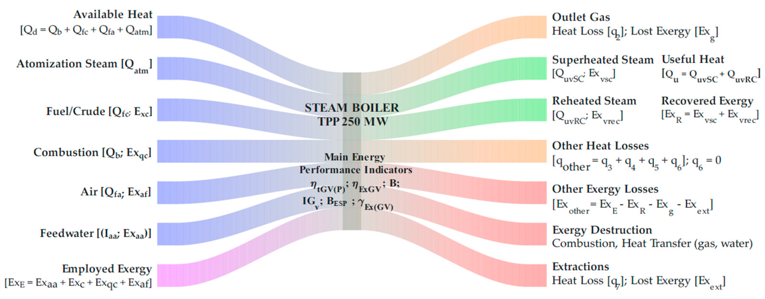
In steam boilers, thermal and exergetic efficiencies are commonly used as energy performance indicators [35]. However, given that the installation under study operates within a TPP, additional indicators are incorporated for a comprehensive analysis: fuel consumption, steam production index, specific fuel consumption relative to total electricity production, and exergy loss. The methodology for energy evaluation, tailored to the investigated boiler, is detailed in the following subsections (Section 2.1, Section 2.2 and Section 2.3), based on a general framework of thermo-exergetic analysis [13] and adapted to the technological characteristics of the studied installation (Figure 1), while branch thickness is uniform and is used only to illustrate the qualitative relationships among the main input, output, and loss streams. A detailed representation of exergy flows considered in the balance is shown in Section 3.3, which provides a Sankey diagram of the input, destroyed, and lost exergies for the two fuels under study.
Figure 1. Conceptual Sankey representation of the energy and exergy scheme of the studied boiler.

2.1. Gross Thermal Efficiency and Heat Losses

The thermal efficiency can be calculated using the direct method (DM, Equation (1)) or the indirect method (IM). The direct method requires measurements of superheated and reheated steam, fuel, air, and atomizing steam parameters [9].
η t G V D M = D v S C I v S C I a a + D v R C I v S R C ( 2 ) I v E R C ( 1 ) ( Q b + Q f c + Q f a + Q a t m ) B M 100
where ηtGVDM represents the gross thermal efficiency of the boiler (%); DvSC is the mass flow rate of superheated steam (kg/s); IvSC and Iaa denote the specific enthalpy of superheated steam and feedwater (kJ/kg), respectively; DvRC refers to the mass flow rate of reheated steam (kg/s); IvSRC(2) and IvERC(1) correspond to the specific enthalpies of the reheated steam at the outlet of reheater 2 and the inlet of reheater 1, respectively, also expressed in kJ/kg; and BM is the fuel consumption measured at the steam generator (kg/s) [36].
The boiler produces superheated steam and reheats steam in two stages. The physical heat of the air (Qfa ≈ 0) is neglected, as it is not preheated by external sources [37]. The heat input is calculated as:
Q b = 339.2 C t + 1030.4 H t 108.9 O t S t 25.14 W t
Q f c = t c 1.737 + 0.0025 t c
Q a t m = D v a t m I v a t m I v s g v
where Qb is the combustion heat (kJ/kg); Qfc is the heat supplied by the preheated fuel (kJ/kg); Qatm is the heat contributed by the atomized steam (kJ/kg); Ct, Ht, Ot, St, and Wt are carbon, hydrogen, oxygen, sulfur, and moisture content in the fuel, respectively (all expressed as main mass fractions (%); Tc is the fuel temperature (°C); Dvatm is the mass flow rate of atomized steam (kgsteam/kgFuel) (typically Dvatm = 0.02–0.1 kgsteam/kgFuel for TPP boilers); and Ivatm and Ivsgv are the specific enthalpies of the steam used for atomization and the steam at the boiler outlet (kJ/kg), respectively.
The indirect method (Equation (5)) requires measurements of gas temperature, chemical composition, superheated steam flow, and extractions, followed by the heat loss calculations [38].
η t G V I M = 100 q 2 + q 3 + q 4 + q 5 + q 6 + q 7
where ηtGVIM is the gross thermal efficiency of the steam generator (calculated by IM), expressed in (%), while q2, q3, q4, q5, q6, and q7 represent the heat losses associated with combustion gases, the incomplete chemical and mechanical combustion, the heat transfer to the surroundings, the unburned residues extracted from the furnace, and the extractions carried out in the dome, respectively, all expressed as percentages [39].
q 2 = I s g v α I a f o 100 q 4 Q d
where
I s g v = I g o + α 1 I a i r e o + I c
α = N 2 N 2 3.76 ( O 2 0.5 C O 0.5 H 2 2 C H 4 )
N 2 = 100 C O + R O 2 + O 2 + H 2 + C H 4
where I s g v   is the enthalpy of the flue gases (kJ/kg); α is the excess air coefficient (dimensionless); I a f o   and I g o are the theoretical enthalpy of cold air and flue gases (kJ/kg), respectively; I a i r e o is the enthalpy of the theoretical air quantity, in kJ/kg; Ic is the enthalpy of volatile ash in the gases (kJ/kg); and N2, O2, CO, H2, CH4, and RO2 are the concentrations of nitrogen, oxygen, carbon monoxide, hydrogen, methane, and triatomic gases in the dry flue gases, all expressed as volume percentages.
Losses q3 and q4 are determined as [35]:
q 3 = 126.4 C O + 108 H 2 + 358.1 C H 4 Q d 1.86 C t + 0.375 S t R O 2 + C O + C H 4 100 q 4
q 4 = q 4 p + q 4 v
where q4p and q4v represent the heat losses due to mechanical unburned residues on the grate and volatile matter, respectively, expressed as percentages.
For liquid fuels, q4p = 0 because they do not produce unburned residues on the grate. Consequently, the Bacharach Index (BI) is used to estimate the magnitude of the total loss (q4 = q4v). The recommended values are provided in Table 1 [1].
Table 1. Loss due to volatile incomplete combustion (q4v) according to Bacharach Index.
Heat loss q5 accounts for radiation, conduction, and convection losses through open registers, walls, the floor, and the ceiling [39]:
q 5 = q 5 D N D N v s c D R v s c
where q5DN is the heat loss at nominal steam production (%), while DNvsc and DRvsc are the nominal and actual superheated steam mass flow rates (kg/s). Dome extraction heat loss is calculated as follows [1]:
q 7 = G e I e Q d B M 100
where Ge is the extraction steam flow rate—Ge = (0.003–0.03) · DvSC for TPP boilers—(kg/s) and Ie is the specific enthalpy of the extracted steam (kJ/kg).
Fuel consumption (BC) is verified using ηb by integrating Equations (1) and (5):
B C = D v S C I v S C I a a + D v R C I v S R C ( 2 ) I v E R C ( 1 ) Q b + Q f c + Q a t m 100 q 2 + q 3 + q 4 + q 5 + q 6 + q 7 100 B M

2.2. Steam Generation Index and Specific Fuel Consumption

In addition to fuel consumption (BM) and thermal efficiency (ηb), other efficiency indicators relevant for TPP boilers include the steam generation index (IGv); specific fuel consumption (BEsp); exergetic efficiency (ηex); and exergy loss (Exp). The steam generation index is defined as [40]:
I G v = D v S C B M D v S C B C
The total fuel supply, whether measured (BM) or calculated (BC), corresponds to all the fuel delivered to the boiler burners. However, this value does not represent the actual burned fuel, as a small portion remains unburned due to mechanical losses. The effective burned fuel flow (BQ) is determined using Equation (16), as proposed by Cabello [41]:
B Q = B M 1 q 4 100 B C 1 q 4 100
Equivalent fuel consumption considers the correction factor (F) for different fuels [42]:
B E = B M F B C F
F = G E Q S M Q S ( r e f ) G E Q S C Q S ( r e f )
Q S C = 339.2 C t + 1257 H t 108.9 O t S t
where QS(ref) = 43,160.00 kJ/kg; BC, BQ, and BE represent the calculated, burned, and equivalent fuel consumption (kg/s); F is the correction factor for the analyzed fuel (dimensionless); GE is the specific gravity of the fuel at 15.5 °C (GE = 0.95–1.05, for heavy fuels), dimensionless; QS(M) and QS(C) are the higher heating values (measured and calculated, respectively) of the analyzed fuel; and QS(ref) is the reference higher heating value (kJ/kg).
Specific fuel consumption is calculated as:
B E s p = B M G E Q S M Q S ( r e f ) P E ( T P P ) B C G E Q S C Q S ( r e f ) P E ( T P P )
where BEsp is the specific fuel consumption (g/kW·h) and PE (TPP) is the rated power output of the TPP (MW).

2.3. Exergetic Efficiency and Exergy Loss

Exergetic efficiency is calculated as [43,44]:
η E x ( G V ) = E x R E x E 100
where ηEx is the exergetic efficiency (%), while ExR and ExE are the recovered and employed exergies (J/s).
All exergy calculations were performed using a reference (dead) state of T0 = Tma = 305.15 K (32 °C) and P0 = Pma = 101.325 kPa (1 atm), corresponding to the average ambient conditions during the measurement campaign (Table 2).
Table 2. Operating parameters measured in the steam boiler.
The exergies of superheated steam (Exvsc); reheated steam (Exvrec); feedwater (Exaa); and extractions (Exext) are:
E x v s c = m v s c h s ( v s c ) h m a ( v s c ) T m a S s ( v s c ) S m a ( v s c )
E x v r e c = m v r e c h s ( v r e c ) h m a ( v r e c ) T m a S s ( v r e c ) S m a ( v s c )
E x a a = m a a h s ( a a ) h m a ( a a ) T m a S s ( a a ) S m a ( a a )
E x e x t = m e x t h s ( e x t ) h m a ( e x t ) T m a S s ( e x t ) S m a ( e x t )
where Ex is the exergy of the corresponding flow (J/s); m is the mass flow rate (kg/s); h is the specific enthalpy (J/kg); S is the specific entropy (J/kg·K); and Tma is the ambient temperature (K).
The exergies of fuel (Exc); combustion heat (Exqc); cold air (Exaf); and flue gases (Exg) are:
E x c = B M t c 1.737 + 0.0025 t c
E x q c = B M 1 q 4 100 Q b 1 T m a T C o m b
E x a f = I a f Q a
E x g = I s g v Q g V g
As stated in Cabello [41]:
Q a = β 1 B M 1 q 4 100 V a o α h T a f + 273.15 273.15 1.01 1 0 5 h b
Q g = β 1 B M 1 q 4 100 V g o + α a v 1 V a o T g + 273.15 273.15 1.01 1 0 5 h b
where Tcomb is the maximum combustion temperature (K); Iaf is the actual enthalpy of the cold air (kJ/m3); Qa and Qg are the airflow and flue gas flow rates from the forced and induced draft fans (FDFs and IDFs) (m3/s); Vg is the actual gas volume (m3N/kg); β1 is the fuel feed reserve coefficient (β1 = 1.05 for Dvsc > 5.6 kg/s), dimensionless; V0 is the theoretical dry-air volume (m3N/kg); αh and αav are the excess air coefficients at the furnace and the FDF inlet—from Equation (8)—(dimensionless); Taf is the temperature of the air entering the FDFs (°C); hb is the barometric pressure (Pa); Tg is the temperature of the flue gases at the IDF inlet (°C); and V0 is the theoretical gas volume (m3N/kg).
Parameters Vg, Vo, and Vo are determined using Equations (32)–(34). To compute them, it is necessary to know the chemical composition of the fuel, the air humidity, and the other previously defined parameters.
V g = V g o + α 1 V a o + 0.00161 d α 1 V a o
V a o = 0.0889 C t + 0.375 S t + 0.265 H t 0.0333 O t
V g o = 1.866 C t + 0.375 S t 100 + 0.79 V a o + 0.8 N t 100 + 0.111 H t + 0.0124 W t + 0.00161 d V a o + 1.24 D v a t m B M
where d—air humidity, in gwater/kgdry air (for Cuba, d = 13–23 gwater/kgdry air).
Then, the exergetic efficiency ηEX(GV) and the exergy destruction ratio γEX(GV) are calculated as:
η E x ( G V ) = E x R G V E x E G V 100 = E x v s c + E x v r e c E x a a + E x c + E x q c + E x a f 100
γ E x G V = 100 η E x ( G V ) = E x P G V E x E G V 100 = E x E G V E x R G V E x E G V 100
where ηEX(GV) is the exergy efficiency of the steam generator (GV), %; γEX(GV) is the exergy destruction ratio of the GV (%); and ExP(GV) and ExE(GV) are the lost and supplied exergies (J/s), respectively.
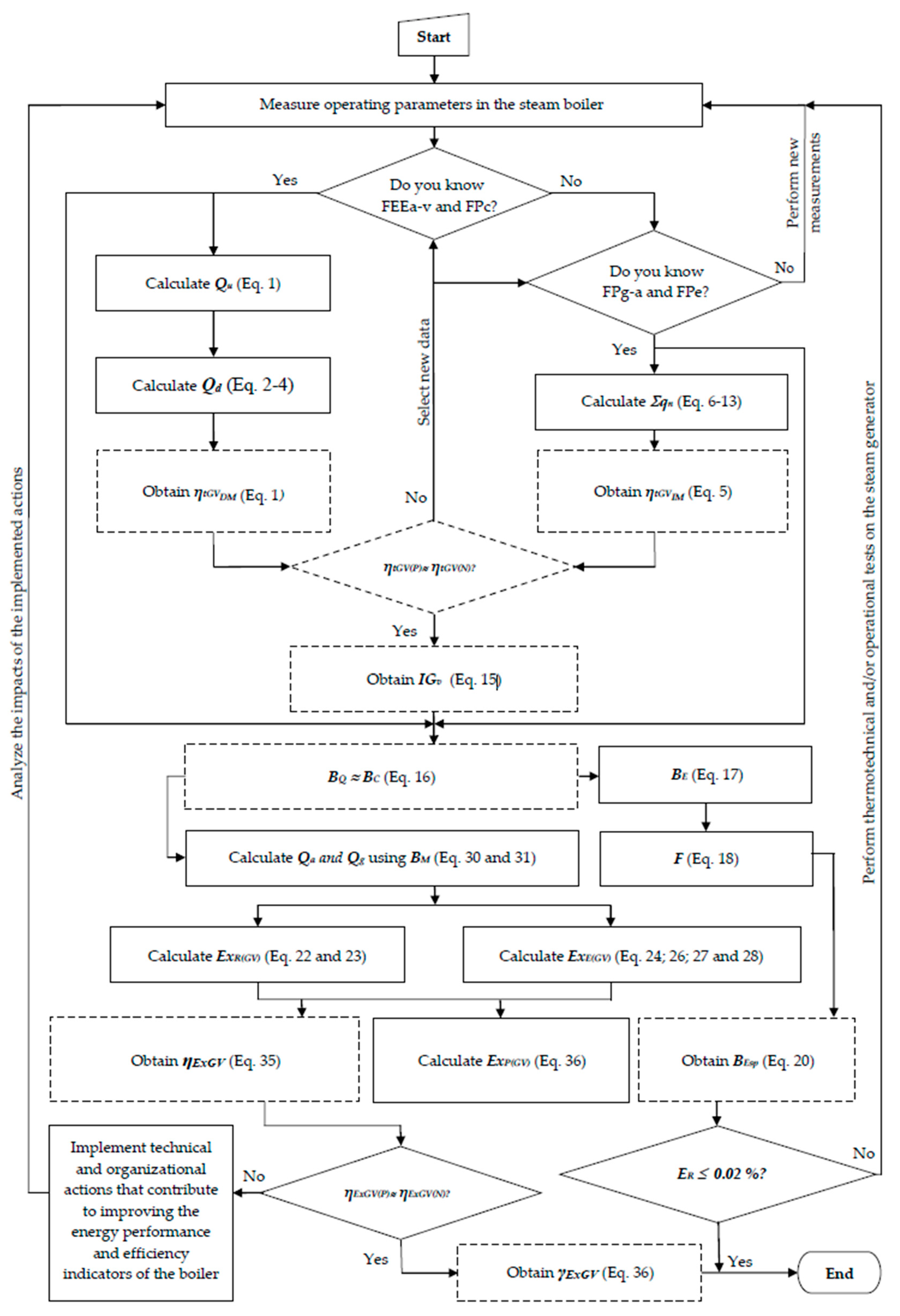
The energy balance procedure is systematized in Figure 2, which constitutes the primary contribution of this work. Implemented in Mathcad 15, the integrated diagnostic methodology is practical for the thermo-exergetic analysis of complex boilers in conventional thermal plants, enabling performance evaluation under different fuels and load conditions. Partial implementation yielded satisfactory results in small TPPs of the Cuban nickel industry [1,13]. Legend: FEEa-v (expenditures and thermodynamic properties of feedwater, superheated steam, reheated steam, and atomization steam); FPc (fuel expenditure and properties); FPg-a (flue gas and air expenditures and properties); FPe (extraction flowrate, enthalpy, and entropy); and ER (relative error).
Figure 2. Flowchart of the integrated diagnostic procedure for determining boiler efficiency indicators.

2.4. Boiler Measurements

Measurements were carried out during operation with two fuels (fuel and crude) of different characteristics [45,46]. The mean values of 30 determinations of operating parameters were calculated (Table 2), followed by the energy evaluation. A passive experiment was conducted due to the continuous operation of the boiler [47].
Measurements were performed using calibrated instruments certified by the TPP Instrumentation and Control Department and used by operators, administrative staff, and researchers. The chemical composition of the fuel and the lower heating values were determined in specialized laboratories using standardized ASTM methods (Table 3).
Table 3. Measurements that were performed on fuels and flue gases.
The following methods were applied: D-4698 (Higher Heating Value); D-1298 (Density and Gravity at 15 °C); D-1548 (Asphaltenes); D-473 (Mechanical Impurities); D-445 (Viscosity at 50 °C); D-382 (Ash); D-189 (Conradson Carbon Residue); D-129 (Sulfur); D-95 (Water); and D-93 (Flash Point); All measured parameters complied with the minimum and maximum thresholds reported in the scientific literature [1]. Performance indicators were calculated using Mathcad 15. Thermodynamic properties were determined using tables [41], online applications, and interpolation methods. The gas composition was measured using ULTRAMAT 23 analyzers powered by 230 V AC, with a 4–20 mA output signal. The equipment used corresponds to model 7MB2335-2CP10-3AA1-Z-A31, with the following measurement ranges: O2 (0–25%); CO2 (0–50%); CO (0–250 mg/m3); SO2 (0–400 mg/m3); and NO (0–250 mg/m3).

3. Results and Discussions

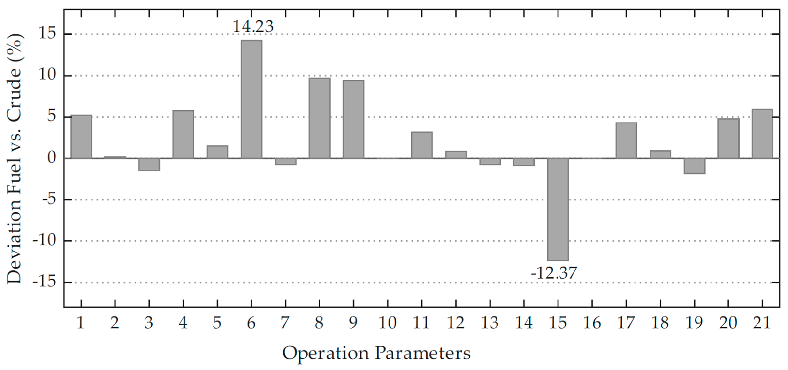
This section analyzes the main findings of the boiler energy evaluation. Preliminary observations indicate that the operating parameters varied when using crude compared to fuel, the latter being the design fuel. The values of the specific parameters are derived from Table 2 and are illustrated in Figure 3.
Figure 3. Deviation between measured operating parameters (listed in Table 2) when using fuel oil and crude oil in the steam boiler.
Generally, the parameter deviations were small (±10%), except for reheater inlet pressure and feedwater temperature (parameters 6 and 15, Table 2). The former resulted from increased expansion work in the high-pressure turbine stage, while the latter resulted from enhanced heat transfer in low-temperature zones (economizers). Both turbine work and feedwater heating were higher with crude, aimed at maximizing its lower energy content compared to fuel. However, this operation increases corrosion risks in the gas evacuation system (ducts, induced draft fans, chimney) due to sulfuric acid (H2SO4) formation, raising maintenance and equipment costs. Evidence of excessive gas cooling is reflected in the chimney outlet temperature, which was 148.38 °C for crude, 7.46 °C lower than for fuel.

3.1. Specific Fuel Consumption

Steam flow rate, the primary energy transport medium for TPP power production, yielded steam-to-power ratios of 3.158 and 3.181 for fuel and crude, respectively. This indicates an additional 23 kg/h of steam per MW with crude, increasing production costs and environmental impact by 3.71 kg of fuel per ton of steam (Table 4). This is attributed to the 1424.5 kJ/kg lower heating value difference between the fuels (Table 3).
Table 4. Specific fuel consumption of the boiler under different operating and maintenance conditions.
Steam quality (pressure and temperature) showed minor variations (0.19 MPa, 0.68 °C) between the fuels within nominal ranges (13.9 MPa, 525 ± 8 °C). Compared to the 220 MW TPP boiler studied by Babatunde et al. [16], the steam-to-power ratio in the present study was less efficient (3.158–3.181 vs. 2.972 t/h per MW). This difference is mainly attributed to the higher sulfur content of the fuels used here (2.18% and 4.86%) compared to the reference fuel (0.3% sulfur), which affects flue gas properties and heat recovery (Table 5). The exergy destruction values obtained (≈41%) are in line with those reported by Abuelnuor et al. [27] for a Sudanese power plant boiler, where the combustion chamber was identified as the main source of irreversibilities (39.8% of input exergy).
Table 5. Impact of fuel quality on selected parameters of the steam generator.

3.2. Excess Air and Air/Gas Flows

The fuel type influences excess air and gas volumes, affecting chimney design, fan selection, and boiler efficiency [13]. The excess air was 22.7% and 26.4% for fuel and crude, respectively (Table 6), exceeding the recommended 10–15% for steam atomized fuel combustion [48]. Crude’s high sulfur content (4.86%) necessitated additional air, requiring solvents, dispersants, and optimized combustion strategies [20,33]. These were partially implemented.
Table 6. Air excess coefficient under different operating conditions.
For TPP heavy fuel oil boilers, the furnace excess air coefficient should be 1.03–1.15 for loads of 50–100% nominal [1]. Non-compliance in the studied boiler resulted from inadequate maintenance and fuel properties. Previous studies [15] showed that at 150–180 MW loads, excess air could be reduced to 11.1–11.7% with crude 2 (7.17% sulfur) through proper maintenance and operational practices [13]. The increases in load from 58 to 61% reduced the excess air by 3.7% (fuel vs. crude) and 5% (crude 2, 61–101% load). Maintenance deficiencies increased excess air by 11 at 61% load, despite fuel’s lower sulfur content.
Air and gas flows (Qa, Qg) increased with TPP load from 155.26 MW (crude) to 165.00 MW (fuel) (Table 7), as expected, due to higher steam and fuel demands [49]. These flows impact on net thermal efficiency (gross efficiency minus auxiliary equipment consumption), affecting 2000 kW forced and induced draft fans and fuel pumping systems [50,51]. Flows exceeded post-maintenance values by 30.41–31.35% at 61% load [15], equivalent to 82.6–83.8% load (206.6–209.6 MW), indicating untapped efficiency potential.
Table 7. Air and gas flow rates under comparable load conditions.

3.3. Boiler Efficiencies

Steam quantity and quality determine useful heat and thermal efficiency (Table 8). The boiler produced high-quality steam near design parameters but had low productivity (61 and 58% of nominal for fuel and crude) due to partial TPP loads (66 and 62%) [16,18,19,28]. Partial loads risk water vapor condensation in gases, reducing temperatures and increasing corrosion in heat transfer surfaces and gas evacuation systems.
Table 8. Heat output and efficiency indicators of the boiler under selected fuel conditions.
The available heat (Qd) was higher with fuel (1.234 kJ/kg), driven by its higher lower heating value (Table 3), yielding greater productivity (27.2 t/h) and useful heat (74 · 106 kJ/h). Average thermal efficiencies (90.59 and 90.27%) indicate satisfactory energy utilization but fall below the 94% design value due to irregular maintenance. Prior studies [15] reported efficiencies 1.74–2.06% higher with crude 2. Exergetic efficiencies were below 60%, slightly improved post-maintenance, due to irreversibilities and temperature differences [13].
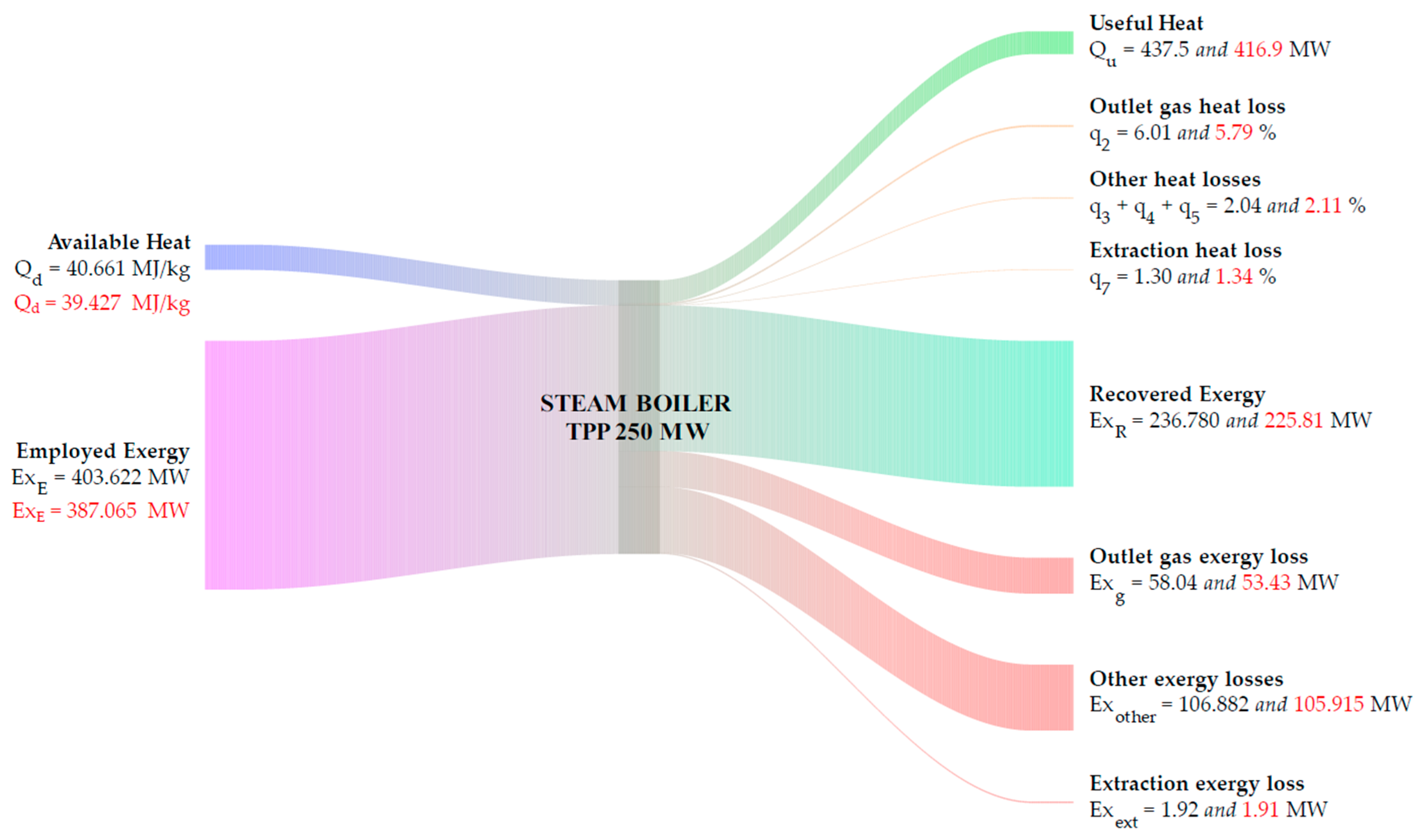
The primary exergy destruction occurs in the combustion chamber, where the flame temperature (≈1800 K) is much higher than the working fluid temperature (≈500 K), generating large irreversibilities. Excess air further increases exergy destruction by diluting the combustion products, reducing the effective flame temperature and increasing entropy generation. The temperature gradient between the flue gases and water/steam in the economizer, evaporator, and superheater also contributes to additional exergy destruction. Figure 4 presents a Sankey diagram that quantifies these contributions; for example, the combustion chamber accounts for approximately 70% of the total exergy destruction under the tested conditions whereas fuel oil (black color) and crude oil (red color).
Figure 4. Thermo-exergetic Sankey diagram steam boiler 250 MW under partial load conditions.

3.4. Steam Production Index and Specific Fuel Consumption

The steam production index (IGv, tsteam/tfuel) and specific fuel consumption (BEsp, gfuel/kW·h) indicate higher efficiency with fuel, producing 0.53 tsteam/tfuel more and consuming 13.02 g/kW·h less than crude (Table 9). The real thermal efficiencies were 3.41–3.73% below design due to excessive air, fouling, and inadequate maintenance [52,53]. High-sulfur fuels exacerbate fouling and corrosion, reducing heat transfer and increasing aerodynamic resistance [54], impacting boiler availability and socio-economic consequences. The exergy-based sustainability indicators developed by Gungor Celik and Aydemir [55] provide a valuable framework for evaluating system performance under realistic conditions, which can inform future combustion tuning and maintenance planning in industrial steam generators.
Table 9. Steam production index and specific fuel consumption of the TPP.

3.5. Proposed Technical and Organizational Actions to Improve the Thermo-Exergetic Performance of the Boiler

Considering the issues identified in the boiler, including prolonged operation under partial load conditions, inadequate maintenance, and the use of a fuel different from the original design specification (i.e., Enhanced Crude Oil 650) that have resulted in suboptimal thermo-exergetic performance of the system (Figure 4), the implementation of the following actions is recommended [1]:
Optimize the boiler energy management system through the application of the ISO 50001 standard [56]. This framework enables systematic monitoring and evaluation of steam generation processes, guiding continuous improvement in alignment with the energy policies of the power plant and national objectives.
Operate the steam generator at or near nominal load, whenever possible, to minimize inefficiencies associated with underutilization, reduce the likelihood of major mechanical failures, and maintain operational safety margins.
Preheat combustion air and ensure adequate air supply to enhance combustion efficiency and increase available exergy. This requires a detailed analysis of the mechanisms of heat transfer in the presence of chemical reactions, particularly in fossil fuel boilers [14].
Operate the burners according to established parameters—atomization flow and pressure, fuel preheating temperature, fuel moisture content, and degree of preparation—to ensure stable and efficient combustion.
Minimize excess air levels and maintain optimal α values during partial load operation to reduce energy consumption by forced and induced draft fans (FDFs and IDFs).
Maximize the recovery of sensible heat from combustion gases to reduce the temperature of the gas outlet of the stack, avoiding water vapor condensation and associated corrosion in the flue gas and water circulation systems.
Maintain clean internal and external heat transfer surfaces and ensure proper technical condition of the boiler insulation to reduce heat losses.
Ensure tight sealing of inspection ports, walls, and registers, and avoid unnecessary openings of these elements to minimize air infiltration and gas leakage.
Maintain the combustion temperature at a stable and optimal level to maximize the conversion of combustion heat into useful exergy.
Reduce the temperature gradient between the working flid (water) and the combustion gases to minimize irreversibilities during heat transfer and phase change, such as implementing multistage feedwater heating in economizers to support this objective.
Through validated numerical methods and simulation tools [57], assess the feasibility of integrating renewable energy sources to preheat feedwater. This strategy would reduce fossil fuel consumption and mitigate the associated environmental impacts [58].
The timely and integrated implementation of these actions, as envisioned in the structured diagnostic procedure presented in Figure 2, will contribute to reducing thermal losses and improving the overall indicators of energy performance of the boiler. However, the positive impacts of such measures remain insufficiently quantified in this specific installation. Future studies will address this gap and explore the use of artificial intelligence for operational and energy optimization in industrial steam generators.

3.6. Estimated Economic Implications

The inefficiencies identified have direct economic consequences. Using the specific fuel consumption values (BEsp) from Table 9 and local fuel prices (approximately 450 USD/t for fuel oil and 420 USD/t for crude), the additional fuel cost associated with operating with crude under the current suboptimal conditions can be estimated. Compared to operation with fuel oil under proper maintenance (BEsp = 238.62 g/kWh), the higher specific consumption for crude (251.64 g/kWh) results in an extra fuel use of about 13.02 g/kWh. For an annual operation of 7000 h at an average load of 160 MW, this translates to approximately 14,560 t of additional fuel per year. Considering the price difference, the net additional annual cost is roughly 1.2 million USD. This estimate, while preliminary, underscores the tangible economic benefit that could be achieved by implementing the corrective measures proposed in Section 3.5.

3.7. Generalization and Applicability of the Methodology

The integrated diagnostic procedure presented in Figure 2 is based on fundamental mass, energy, and exergy balances that are universally applicable to any fossil-fuel-fired steam generator. The coherence verification loop (ER in Figure 2) is a generic tool for improving the reliability of performance assessments by reconciling direct and indirect method results. However, the specific correlations used for certain heat losses—such as the load dependent q5 correlation (Equation (12)) or the treatment of mechanical unburned losses (q4)—must be adapted when applying the methodology to different boiler types (e.g., fluidized bed, grate fired) or to fuels with distinct combustion characteristics (e.g., solid fuels, biomass). Nevertheless, the overall methodological framework is versatile and can be transferred to other industrial boilers after appropriate parameterization.

4. Conclusions

A structured diagnostic procedure was developed for the thermo-energetic evaluation of a 250 MW TPP boiler, enabling precise determination of its energy performance indicators. Applied to the studied steam generator, the procedure proved effective and practical for thermo-exergetic analysis of complex boilers in conventional thermal power plants.
The boiler exhibited superior energy performance with fuel oil (thermal efficiency 90.59% and exergetic efficiency 58.67%) compared to Enhanced Crude 650 (90.27% and 58.34%, respectively). However, these differences were mainly due to operational factors rather than the fuel type, including partial load operation (plant: 66% and 62%; boiler: 61% and 58%), suboptimal combustion adjustments causing elevated excess air (22.7% and 26.4%), and heat transfer surface fouling due to inadequate maintenance.
Key performance indicators—thermal efficiency (ηtGV); exergetic efficiency (ηExGV); exergy loss (γExGV); steam production index (IGv); and specific fuel consumption (BEsp)—revealed progressive deterioration relative to design values. The specific fuel consumption was 238.62 g/kWh for fuel oil and 251.64 g/kWh for crude, indicating an additional fuel cost of approximately 1.2 million USD per year under current operating conditions. Adopting best practices and robust maintenance strategies can unlock significant energy efficiency reserves in the boiler and the TPP.

Author Contributions

Conceptualization, Y.R.-M., Y.C.-M., H.L.L.-A., C.Z., H.J.A.P., B.L.D.l.c. and L.O.; methodology, Y.R.-M., W.Q., Y.C.-M., M.H.-W. and L.O.; software, Y.R.-M., W.Q. and L.O.; validation, Y.R.-M., W.Q. and Y.C.-M.; formal analysis, Y.R.-M., Y.C.-M., H.L.L.-A., C.Z., H.J.A.P., B.L.D.l.c. and M.H.-W.; investigation, Y.R.-M., Y.C.-M., H.L.L.-A., C.Z., H.J.A.P., B.L.D.l.c. and L.O.; resources, H.L.L.-A., C.Z., H.J.A.P., M.H.-W. and B.L.D.l.c.; data curation, Y.R.-M., W.Q., Y.C.-M. and L.O.; writing—original draft preparation, Y.R.-M., Y.C.-M. and L.O.; writing—review and editing, Y.R.-M., W.Q., Y.C.-M., H.L.L.-A., C.Z., H.J.A.P., B.L.D.l.c. and L.O.; visualization, Y.R.-M. and L.O.; supervision, Y.R.-M., Y.C.-M., W.Q., M.H.-W. and L.O.; project administration, Y.R.-M. and W.Q.; funding acquisition, Y.R.-M. and W.Q. All authors have read and agreed to the published version of the manuscript.

Funding

This research received no external funding.

Data Availability Statement

The original contributions presented in this study are included in the article. Further inquiries can be directed to the corresponding authors.

Conflicts of Interest

The authors declare no conflicts of interest.

Abbreviations

The following abbreviations are used in this manuscript:
ASTMAmerican Society for Testing and Materials
BIBacharach Index
DMDirect Method
IMIndirect Method
SGSteam Generator
TPPThermal Power Plant
FDFForced Draft Fan
IDFInduced Draft Fan

References

  1. Mediaceja, Y.R.; Héctor Luis, L.A.; Andres, A.S.-E.; Yanán, C.-M.; Fabián, S.C.M.; Marbelis, L.U.; Ever, G.L. Análisis termoenergético del sistema de generación de vapor de una central térmica de 49 MW. Enfoque UTE 2020, 11, 87–101. [Google Scholar] [CrossRef]
  2. Aliu, S.A.; Ochornma, P.I. Comparative Energy and Exergy Analysis of a Thermal Power Plant with/Without Retrofitted Inlet Air Cooler: A Case Study. Eur. J. Eng. Technol. Res. 2018, 3, 1–9. [Google Scholar] [CrossRef]
  3. Pan, S.-Y.; Snyder, S.W.; Packman, A.I.; Lin, Y.J.; Chiang, P.-C. Cooling water use in thermoelectric power generation and its associated challenges for addressing water-energy nexus. Water-Energy Nexus 2018, 1, 26–41. [Google Scholar] [CrossRef]
  4. Alfonso, H.L.L.; Mediaceja, Y.R.; Tamayo, E.T. Procedimiento para determinar la variación de temperatura del petróleo pesado con comportamiento seudoplástico en tuberías conductoras. Ingeniare. Rev. Chil. Ing. 2024, 31, 40. [Google Scholar] [CrossRef]
  5. González, A.V.; Suárez, J.M.C.; Molina, L.R.P. Evaluación termoexergética de un generador de vapor pirotubular compacto. Ing. Investig. Tecnol. 2020, 21, e1696. [Google Scholar] [CrossRef]
  6. Kılkış, B. Development of an Exergy-Rational Method and Optimum Control Algorithm for the Best Utilization of the Flue Gas Heat in Coal-Fired Power Plant Stacks. Energies 2019, 12, 760. [Google Scholar] [CrossRef]
  7. Eswaravelu, D.; Narayanasamy, M.; Mohan, U.; Narayanagounder, S. Thermodynamic Analysis of Grate Fired Boiler Efficiency using Biomass Fuels. In Proceedings of the 2024 1st International Conference on Innovative Engineering Sciences and Technological Research (ICIESTR), Muscat, Oman, 14–15 May 2024; pp. 1–5. [Google Scholar] [CrossRef]
  8. Satyavada, H.; Baldi, S. Monitoring energy efficiency of condensing boilers via hybrid first-principle modelling and estimation. Energy 2018, 142, 121–129. [Google Scholar] [CrossRef]
  9. Calvo-González, A.E.; Reyes-Becquer, N.; Aballe-Infante, L.; López-García, E.; Domínguez-Machado, R.; Santé-Heredia, V.; Fernando-Mfumo, A. Cálculo térmico normativo de calderas digitalizado para el análisis de regímenes estacionarios Boilers normative thermal calculation digitized for stationary régimes analysis. Ing. Mecánica 2019, 22, 100–107. [Google Scholar]
  10. Husnain, N.; Khan, W.A.; Qureshi, S.R.; Siddiqui, F.A.; Wang, E.; Mehmood, A. Exergetic and energetic analysis of a 210 MW Thermal Power Plant in Pakistan. Univ. Eng. Technol. Taxila. Tech. J. 2017, 22, 66–71. [Google Scholar]
  11. Eke, M.N.; Onyejekwe, D.C.; Iloeje, O.C.; Ezekwe, C.I.; Akpan, P.U. Energy and exergy evaluation of a 220MW thermal power plant. Niger. J. Technol. 2018, 37, 115–123. [Google Scholar] [CrossRef]
  12. Patel, S.S.L.; Agrawal, G.K. Energy and exergy analysis for performance improvement of coal fired thermal power plant. Int. J. Eng. Sci. Res. Technol. 2018, 7, 497–507. [Google Scholar] [CrossRef]
  13. Retirado-Mediaceja, Y.; Camaraza-Medina, Y.; Sánchez-Escalona, A.; Laurencio-Alfonso, H.; Salazar-Corrales, M.; Zalazar-Oliva, C. Thermo-exergetic assessment of the steam boilers used in a cuban thermoelectric facility. Int. J. Des. Nat. Ecodyn. 2020, 15, 291–298. [Google Scholar] [CrossRef]
  14. Centeno-González, F.O.; Lora, E.E.S.; Nova, H.F.V.; Neto, L.J.M.; Reyes, A.M.M.; Ratner, A.; Ghamari, M. CFD modeling of combustion of sugarcane bagasse in an industrial boiler. Fuel 2017, 193, 31–38. [Google Scholar] [CrossRef]
  15. Camaraza-Medina, Y.; Retirado-Mediaceja, Y.; Hernandez-Guerrero, A.; Luviano-Ortiz, J.L. Energy efficiency indicators of the steam boiler in a power plant of Cuba. Therm. Sci. Eng. Prog. 2021, 23, 100880. [Google Scholar] [CrossRef]
  16. Babatunde, D.; Anozie, A.; Omoleye, J.; Babatunde, O. An Air-Fuel Ratio Parametric Assessment on Efficiency and Cost of a Power Plant Steam Boiler. Process Integr. Optim. Sustain. 2021, 5, 561–575. [Google Scholar] [CrossRef]
  17. Tic, W.J.; Guziałowska-Tic, J. A System of Improving Energy and Ecological Efficiency, Using the Example of Fuel Oil Combustion in Power Plant Boilers. Energies 2023, 16, 1107. [Google Scholar] [CrossRef]
  18. Nemitallah, M.A.; Nabhan, M.A.; Alowaifeer, M.; Haeruman, A.; Alzahrani, F.; Habib, M.A.; Elshafei, M.; Abouheaf, M.I.; Aliyu, M.; Alfarraj, M. Artificial intelligence for control and optimization of boilers’ performance and emissions: A review. J. Clean. Prod. 2023, 417, 138109. [Google Scholar] [CrossRef]
  19. Cho, M.; Seo, Y.; Park, E.; Chang, D.; Han, S. Process design and energy assessment of an onboard carbon capture system with boilers or heat pumps for additional steam generation. Ships Offshore Struct. 2024, 19, 1309–1322. [Google Scholar] [CrossRef]
  20. Janta-Lipińska, S.; Shkarovskiy, A.; Chrobak, Ł. Improving the Fuel Combustion Quality Control System in Medium Power Boilers. Energies 2024, 17, 3055. [Google Scholar] [CrossRef]
  21. Kanani, B.; Zahedi, A. Efficiency enhancement by integration of fuel cells in downstream of power plants: Next step in energy generation systems. Next Energy 2025, 7, 100226. [Google Scholar] [CrossRef]
  22. Moreno-Gamboa, F.; Escudero-Atehortua, A.; Nieto-Londoño, C. Alternatives to Improve Performance and Operation of a Hybrid Solar Thermal Power Plant Using Hybrid Closed Brayton Cycle. Sustainability 2022, 14, 9479. [Google Scholar] [CrossRef]
  23. Kumar, V.; Saxena, V.K.; Kumar, R.; Kumar, S. Energy, exergy, sustainability and environmental emission analysis of coal-fired thermal power plant. Ain Shams Eng. J. 2024, 15, 102416. [Google Scholar] [CrossRef]
  24. Elwardany, M.; Nassib, A.; Mohamed, H.A. Advancing sustainable thermal power generation: Insights from recent energy and exergy studies. Process Saf. Environ. Prot. 2024, 183, 617–644. [Google Scholar] [CrossRef]
  25. Wang, T.; Wang, C.; Yan, H.; Liu, Z.; Ma, S. Optimization of secondary air system for enhanced combustion efficiency and CO2 emission reduction in 1000MW boilers. Results Eng. 2025, 27, 105977. [Google Scholar] [CrossRef]
  26. Mardones, C. Contribution of the carbon tax, phase-out of thermoelectric power plants, and renewable energy subsidies for the decarbonization of Chile—A CGE model and microsimulations approach. J. Environ. Manag. 2024, 352, 120017. [Google Scholar] [CrossRef]
  27. Varganova, A.V.; Khramshin, V.R.; Radionov, A.A. Operating Modes Optimization for the Boiler Units of Industrial Steam Plants. Energies 2023, 16, 2596. [Google Scholar] [CrossRef]
  28. Abuelnuor, A.A.; Suliman, M.M.H.; Abuelnour, M.A.; Younis, O.; Mohamed, E.F. Exergy analysis of the boiler in phase 3 of the Khartoum North power plant. Results Eng. 2024, 21, 101919. [Google Scholar] [CrossRef]
  29. Elwardany, M. Enhancing steam boiler efficiency through comprehensive energy and exergy analysis: A review. Process Saf. Environ. Prot 2024, 184, 1222–1250. [Google Scholar] [CrossRef]
  30. Kabeyi, M.J.B.; Olanrewaju, O.A. Performance Analysis and Evaluation of Muhoroni 60MW Gas Turbine Power Plant. In Proceedings of the 2021 International Conference on Electrical, Computer, Communications and Mechatronics Engineering (ICECCME), Mauritius, Mauritius, 7–8 October 2021; pp. 1–8. [Google Scholar] [CrossRef]
  31. Ntonda, J.; Lekané, N.N.; Boupda, O.; Kamhoua, A.; Lontsi, F. Thermodynamic analysis of a combined cooling and power system driven by waste exhaust heat from industrial boilers in the energy and climatic context of the city of Douala, Cameroon. Int. J. Thermofluids 2025, 26, 101150. [Google Scholar] [CrossRef]
  32. Zheng, S.; Liu, B.; Mohammadian, E.; Liu, Y.; Tian, S. Sustainable in-situ steam injection approach for shale oil extraction in Xinjiang, China: A technical and economic analysis. Energy 2024, 308, 132986. [Google Scholar] [CrossRef]
  33. Jacas-Portuondo, F.; Peña-Pupo, L.; Forgas-Brioso, M.R.; Silva-Lora, E.E.; Taborda-Giraldo, J.A.; Nuñez-Alvarez, J.R. Efficiency Improvement in a Crude Oil Heating Furnace Based on Linear Regulation Control Strategies. Energies 2025, 18, 1578. [Google Scholar] [CrossRef]
  34. Chen, F.; Zhang, W.; Liu, Y.; Cai, J.; Zhang, J.; Wang, X.; Su, Q. Simulation and 4E analysis of a novel trigeneration process using a gas turbine cycle combined with a geothermal-driven multi-waste heat recovery method. Process Saf. Environ. Prot. 2023, 176, 1026–1047. [Google Scholar] [CrossRef]
  35. Arjona, A. Revisión de Métodos Para la Determinación de Pérdidas y Eficiencia Energética en Generadores de Vapor. Master’s Thesis, Universidad de Sevilla, Sevilla, Spain, 2019; p. 170. [Google Scholar]
  36. Camaraza-Medina, Y.; Hernandez-Guerrero, A.; Luviano-Ortiz, J.L. View factor for radiative heat transfer calculations between triangular geometries with common edge. J. Therm. Anal. Calorim. 2023, 148, 4523–4539. [Google Scholar] [CrossRef]
  37. Hafdhi, F.; Khir, T.; Ben Yahyia, A.; Ben Brahim, A. Energetic and exergetic analysis of a steam turbine power plant in an existing phosphoric acid factory. Energy Convers. Manag. 2015, 106, 1230–1241. [Google Scholar] [CrossRef]
  38. Ganapathy, V. Industrial Boilers and Heat Recovery Steam Generators; Texas: London, UK, 2002. [Google Scholar]
  39. Borges, R.J.; Rodríguez, M.J.L.; Bravo, O.H.; Medell, E.C. Influencia de los parámetros operacionales en la eficiencia termodinámica de instalaciones de baja y mediana capacidad. Cent. Azúcar 2016, 42, 80–88. [Google Scholar]
  40. Falcón, M.C.; Izquierdo, Y.C.; Vicente, I.A.; Suárez, E.G. Evaluación Del Sistema Energético En El Central Azucarero Quintín Bandera. Energy Syst. Eval. Quintín Bandera Sugar Fact. 2019, 46, 66–78. [Google Scholar]
  41. López, R.C.; Doménech, R.L.; GarcíaVacas, D.S. Problemas Resueltos de Termotecnia; Universitat Jaume I: Castello de la Plana, Spain, 2019. [Google Scholar]
  42. Quitiaquez, W.; Meneses, H.; Quitiaquez, P.; Simbaña, I. Regeneration of Deteriorated Internal Combustion Engine Components used in Thermal Power Plants. Rev. Técnica Energía 2025, 21, 48–59. [Google Scholar] [CrossRef]
  43. Tozlu, A.; Büyükmurat, Y.T.; Özahi, E. Thermoeconomic Analyses of An Actual Power Plant. Turk. J. Electromechanics Energy 2020, 5, 9–15. [Google Scholar]
  44. Granet, I.; Bluestein, M. Thermodynamics Heat Power, 8th ed.; Taylor & Francis: New York, NY, USA.
  45. Laurencio, H.; Delgado, Y. Reological Properties of Emulsions of Petroleum Weighed in Water. Rev. Chil. Ing. 2008, 16, 244–249. [Google Scholar]
  46. Alfonso, H.L.; Hernández, A.G.; Mediaceja, Y.R. Modelado de la viscosidad aparente de un petróleo crudo de 11°API con comportamiento no newtoniano. Ingeniare 2017, 25, 674–680. [Google Scholar] [CrossRef]
  47. Lobaina, A.A.L. Elementos Teóricos y Prácticos de la Investigación Científico-Tecnológica; Editorial Felix Varela: Havana, Cuba, 2022. [Google Scholar]
  48. Albán, C.A.P.; García, A.C.; Benalcázar, J.R.T. Diseño e implementación de un sistema de control para mejorar la calidad de los gases de combustión de una caldera pirotubular de 5 BHP. Enfoque UTE 2016, 7, 55–68. [Google Scholar] [CrossRef]
  49. Camaraza-Medina, Y.; Sánchez-Escalona, A.; Retirado-Mediaceja, Y.; García-Morales, O. Use of Air Cooled Condenser in Biomass Power Plants: A Case Study in Cuba. Int. J. Heat Technol. 2020, 38, 425–431. [Google Scholar] [CrossRef]
  50. Laurencio-Alfonso, H.L.; Pérez-maliuk, O.; Falcón-Hernández, J.; Retirado-Mediaceja, Y. Modelo para cálculo de pérdidas de presión en tuberías conductoras de petróleo pesado (11o API) Model for the calculation of pressure loss through heavy fuel oil transfer pipelines. Minería y Geol. 2012, 28, 70–86. [Google Scholar]
  51. Laurencio-Alfonso, H.; Mediaceja, Y.; Falcón-Hernández, J.; Tamayo, E.; Corrales, M. Modelo para simulación de la potencia de flujo en tuberías conductoras de petróleo pesado con comportamiento seudoplástico. Ingeniare 2022, 30, 171–179. [Google Scholar] [CrossRef]
  52. Camaraza-Medina, Y.; Escalona, A.A.S.; Cruz-Fonticiella, O.M.; García-Morales, O.F. Method for heat transfer calculation on fluid flow in single-phase inside rough pipes. Therm. Sci. Eng. Prog. 2019, 14, 100436. [Google Scholar] [CrossRef]
  53. Camaraza-Medina, Y.; Sánchez-Escalona, A.A.; Retirado-Mediaceja, Y.; García-Morales, O.F. New Procedure for Thermal Assessment of an Air Cooled Condenser Coupled to Biomass Power Plant. Int. J. Sustain. Dev. Plan. 2020, 15, 1297–1302. [Google Scholar] [CrossRef]
  54. Duporté, M. Efectos De Los Gases Producto De La Combustión En Los Generadores De Vapor. Ing. Energética 2004, 25, 18–30. [Google Scholar]
  55. Celik, A.G.; Aydemir, U. Energy, Exergy Analysis and Sustainability Assessment of a Thermal Power Plant Operating in Various Environmental Conditions Using Real Operational Data. Sustainability 2025, 17, 1417. [Google Scholar] [CrossRef]
  56. ISO 50001:2018; Energy Management Systems—Requirements with Guidance for Use. Nqa: Acton, MA, USA, 2018.
  57. Quitiaquez, W.; Estupiñán-Campos, J.; Nieto-Londoño, C.; Quitiaquez, P. CFD Analysis of Heat Transfer Enhancement in a Flat-Plate Solar Collector/Evaporator with Different Geometric Variations in the Cross Section. Energies 2023, 16, 5755. [Google Scholar] [CrossRef]
  58. Estupiñán-Campos, J.; Quitiaquez, W.; Nieto-Londoño, C.; Quitiaquez, P. Numerical Simulation of the Heat Transfer Inside a Shell and Tube Heat Exchanger Considering Different Variations in the Geometric Parameters of the Design. Energies 2024, 17, 691. [Google Scholar] [CrossRef]
Disclaimer/Publisher’s Note: The statements, opinions and data contained in all publications are solely those of the individual author(s) and contributor(s) and not of MDPI and/or the editor(s). MDPI and/or the editor(s) disclaim responsibility for any injury to people or property resulting from any ideas, methods, instructions or products referred to in the content.

Article Metrics

Citations

Article Access Statistics

Multiple requests from the same IP address are counted as one view.