


Abstract
Existing studies on transverse phonon-polaritons in one-dimensional piezoelectric superlattices, based on the assumption of infinite lateral dimensions (perpendicular to the periodic direction of ferroelectric domains), have shown that only transverse superlattice vibrations with a strain component along the periodic direction can couple with electromagnetic waves to generate transverse phonon-polaritons. Real samples, however, inevitably have finite lateral dimensions, indicating that the infinite-lateral-size model requires modification. In this study, we find that in laterally finite systems, pure transverse superlattice vibrations (those without any strain component along the periodic direction) can also couple with electromagnetic waves, giving rise to a new class of pure transverse phonon-polaritons. Theoretical analysis reveals that the energy of this mode is primarily confined to the crystal surface and propagates as surface waves. Experimental verification confirms the existence of this polariton, and this result provides a new degree of freedom for the design of microwave devices based on piezoelectric superlattices.
1. Introduction
The concept of polaritons originated from Huang’s seminal work in 1951 on the coupling between photons and transverse optical phonons in polar crystals [1], was later formally named “polaritons” by Hopfield [2], and was experimentally confirmed in GaP crystals by Henry and Hopfield in 1965 [3]. Since then, polariton research has expanded from natural crystals to artificially structured materials. In recent years, with the rapid development of microfabrication techniques and near-field optical detection methods, polariton research has entered a new era. The engineering of polaritons has become possible in artificial structures such as piezoelectric superlattices and photonic crystals [4,5,6,7,8,9,10], while various polariton modes and their control methods have been successively explored in emerging systems including hyperbolic materials and two-dimensional heterostructures [11,12,13,14].
Among various artificial structures, piezoelectric superlattices (PSLs) with periodically reversed ferroelectric domains provide a unique platform [4,5,6,7,8,9,10]. Unlike natural ionic crystals, where phonon-polaritons (PP) arise solely from transverse optical phonons, the artificial periodic structure in PSL breaks the translational symmetry of a uniform crystal and introduces new coupling mechanisms. For instance, it has been shown that EM waves can couple with longitudinal superlattice vibrations to generate longitudinal PPs (LPP), which do not exist in natural crystals [6].
Under the assumption of infinite lateral dimensions (perpendicular to the periodic direction), transverse superlattice vibrations with a strain component along the periodic direction can couple with EM waves to produce transverse PPs (TPP) in one-dimensional PSL [4,5,6,7,8,9,10]. This understanding has been widely accepted as the theoretical basis over the past two decades.
However, real PSL samples inevitably have finite lateral dimensions. Even when these dimensions are much larger than the domain period, the infinite-lateral-size model may not fully capture the actual coupling behavior. This raises a key question: in laterally finite systems, can pure transverse superlattice vibrations—those without any strain component along the periodic direction—couple with EM waves? If such coupling exists, it would imply that the theoretical model derived from the infinite-period model needs refinement, and would also provide a new degree of freedom for the design of microwave devices based on piezoelectric superlattices.
To address this question, this paper presents a combined theoretical and experimental investigation. In Section 2, based on the piezoelectric constitutive equations, a theoretical model for the coupling between pure transverse superlattice vibrations and EM waves that generates pure transverse phonon-polaritons is established. Using the plane-wave expansion method, the dielectric function is calculated, and the properties of pure transverse phonon-polaritons are analyzed through dielectric anomaly peaks. Section 3 presents the corresponding experimental results and compares them with the theoretical predictions.
2. Dielectric Function of PSL
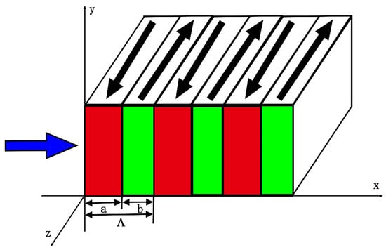
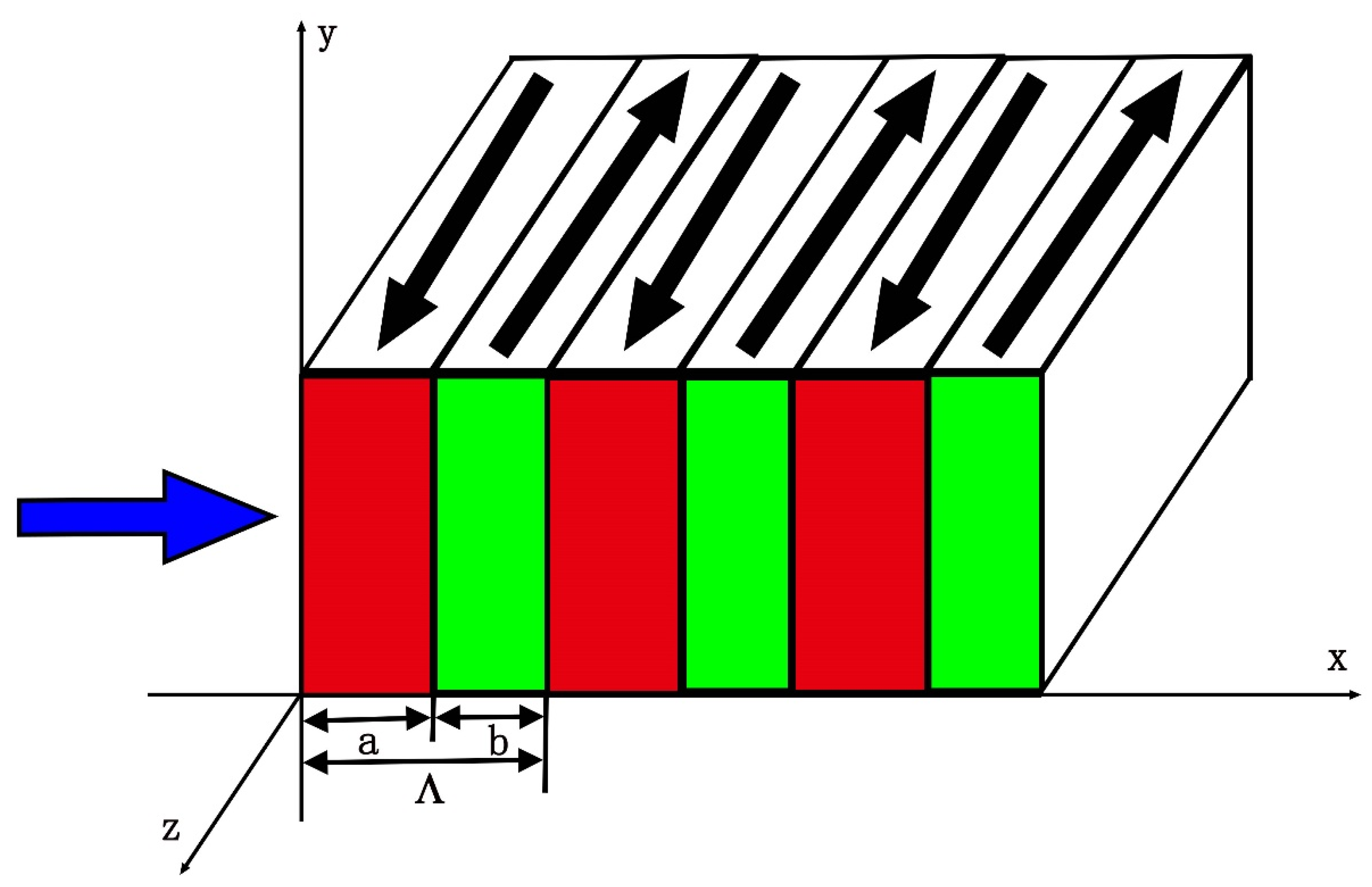
To illustrate the above idea, consider the case where the PSL consists of a periodically poled ferroelectric crystal, e.g., periodically poled LiNbO3 (PPLN). Figure 1 shows a schematic diagram of the PPLN structure, in which the spontaneous polarization is oriented along the z-axis. Positive and negative ferroelectric domains are arranged periodically along the x-axis, and the domain walls lie in the yz-plane. Let a denote the thickness of positive domain and denote the thickness of a negative domain. The domain period is then , and the duty cycle is . Here, only three periods of the PPLN have been shown. We assume that the PPLN has a transverse dimension much larger than the domain period but still exhibits significant finite-size effects (i.e., the boundary conditions are non-negligible).
Figure 1.
Schematic diagram of PPLN. The periodically poled ferroelectric domains are arranged along the x axis. Arrows along the positive z axis indicate the positive domains, and arrows along the negative z axis indicate the negative domains. The leftward arrow denotes the propagation direction of a y-polarized electromagnetic wave. Only three periods of the PPLN are shown.
Due to the piezoelectric effect and the periodic modulation of the piezoelectric coefficients, and accounting for the boundary conditions, the propagation of a y-polarized EM wave along the x-axis will excite a pure transverse and a longitudinal acoustic wave in the PPLN. Acoustic waves and EM waves obey Newton’s equations and Maxwell’s equations, respectively. When excited, the longitudinal mode S1(x, t) and the pure transverse mode S4(x, t) become the dominant vibration modes, both depending on position and time. The simplified piezoelectric and Newton’s equations are as follows [4,5,6]:
here T1,4, E2, and D2 are the stresses, electric field, and electric displacement, respectively, and they depend on position and time. and are the elastic coefficients, and and are the dielectric coefficient and mass density, respectively. The piezoelectric stress coefficients and are periodic in position, and , where
where is the permeability of vacuum.
In the theoretical formulation, a correction factor k (0 ≤ k ≤ 1) is introduced to the piezoelectric coefficient . This factor accounts for the deviation between the response of a finite-sized crystal and that of an idealized one-dimensional infinite periodic model, reflecting the reduced excitation efficiency due to geometric constraints. The physical rationale is as follows. Although the lateral dimensions of the PPLN in the y- and z-directions are much larger than the domain period, they remain finite. Consequently, efficient gradient-driven excitation is confined to limited regions such as crystal edges and domain boundaries. Moreover, the energy of the excited pure transverse superlattice mode becomes confined near the surfaces, causing it to propagate primarily as surface acoustic waves. In contrast, the longitudinal mode permeates the entire crystal volume. As a result, the effective piezoelectric coupling volume for the pure transverse mode is substantially smaller than that for the longitudinal mode, leading to a weaker coupling to the external electric field. The factor k quantitatively describes this reduction in excitation efficiency due to geometric constraints.
From the above equations, a pure transverse acoustic wave S4(y, t) and a longitudinal acoustic wave S1(y, t) are excited by and coupled with the original y-polarized EM waves. Accordingly, two types of PPs are generated: the pure TPP and the LPP. Equation (3) shows that, due to the piezoelectric effect and the modulation of piezoelectric coefficients between alternate layers, the pure transverse and longitudinal acoustic waves can induce an additional electric displacement. Equations (4) and (5) are the wave equations that describe the excitation and propagation of the pure transverse and longitudinal acoustic waves in PPLN, respectively.
The properties of PPs can be derived from the frequency-dependent dielectric function [4,5,6]. Thus, the coupling between superlattice vibrations and EM waves is reflected in the dielectric response. In the long-wavelength approximation, the EM wave has a very small wave vector, and its wavelength is much larger than the crystal length. The dielectric function can be assumed to depend only on the circular frequency. Under this approximation, the y-direction dielectric function of PPLN is obtained from Equations (1)–(5) by the plane-wave method [4,5,6]. Substituting Equations (1) and (2) into Equations (4) and (5), respectively, yields
By applying the Fourier transform, the modulation function is expressed as
where
and the reciprocal vector (n is an integer). Substituting Equation (8) into Equations (6) and (7) yields
The dielectric response reflects the coupling between superlattice vibration and EM waves. Substituting Equations (9) and (10) into Equation (3) gives
where
is the relative dielectric constant as a function of circular frequency ω. and are the frequency positions of the pure TPP and LPP, respectively.
3. Results and Discussion
The crystals used in our experiments are a periodically poled lithium niobate crystal co-doped with Y and Mg (PPLN:Y:Mg). PPLN:Y:Mg was grown along the x-axis using the Czochralski method from a melt with a near-congruent Li/Nb ratio of 0.942, containing 1 wt.% Y2O3 and 2 mol% MgO [15,16]. Yttrium doping was employed to facilitate the formation of a periodically poled domain structure, utilizing the rotation-induced growth striations inherent in bulk LiNbO3 single crystals. Magnesium codoping further enhances the stabilization and pinning of domain walls at these striations. The sample was cut perpendicular to the x-axis and polished. Its input and output surfaces, parallel to the domain walls, measured 1 cm × 1 cm. For the specific sample studied here, the domain period was 20.5 μm, and the duty cycle is . The sample contained more than 147 periods, corresponding to a total length of 3.02 mm along the x-axis.
Theoretically, the model established in this work is derived from PPLN crystals with 3m point group symmetry. The material used in the experiment is PPLN:Y:Mg crystal. Since the 3m point group symmetry of the crystal remains unchanged after doping with Y and Mg ions, the experimental data obtained from PPLN:Y:Mg can be used to validate the theoretical model. The preservation of the 3m point group symmetry after doping is demonstrated below.
First, direct experimental evidence comes from conoscopic interferometry. Under low-power laser excitation, this method confirms that Mg2+-doped, Y3+-doped, and Y3+:Mg2+-codoped lithium niobate crystals remain uniaxial, with no alteration of their trigonal symmetry [17,18].
Second, extensive structural studies support that these dopants occupy specific lattice sites without changing the overall crystal framework. Raman spectroscopy [19], nuclear magnetic resonance [20], X-ray diffraction, and neutron diffraction [21] all support the lithium vacancy model, which has been widely accepted. For Mg incorporation, Iyi et al. reconstructed the mechanism based on this model [22]: Mg ions first replace Nb antisites while maintaining a [Li]/[Nb] ratio of 0.94, with complete replacement occurring at 3 mol%; further Mg ions enter Li sites, reducing [Li]/[Nb] to 0.84; beyond this, Mg ions occupy both Nb and Li sites while the [Li]/[Nb] ratio remains constant. Grabmaier et al. [23] further reported two threshold concentrations in this process. For Y incorporation, comprehensive analysis of FTIR, Raman, and UV-vis spectroscopy indicates that yttrium ions preferentially substitute antisite niobium ions in octahedral sites until complete replacement occurs at a threshold of 3 mol% [24].
Collectively, these findings confirm that although the local defect structure may vary with doping concentration and ion type, the macroscopic trigonal symmetry remains intact. Therefore, PPLN:Y:Mg is applicable within our theoretical framework.
If material damping is considered, introducing damping terms into Equations (4) and (5) yields the damped equations of motion. By applying the plane wave expansion method [4,5,6], the complex dielectric function can be derived as follows:
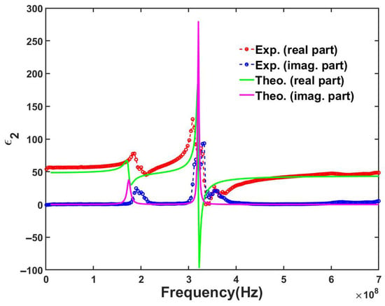
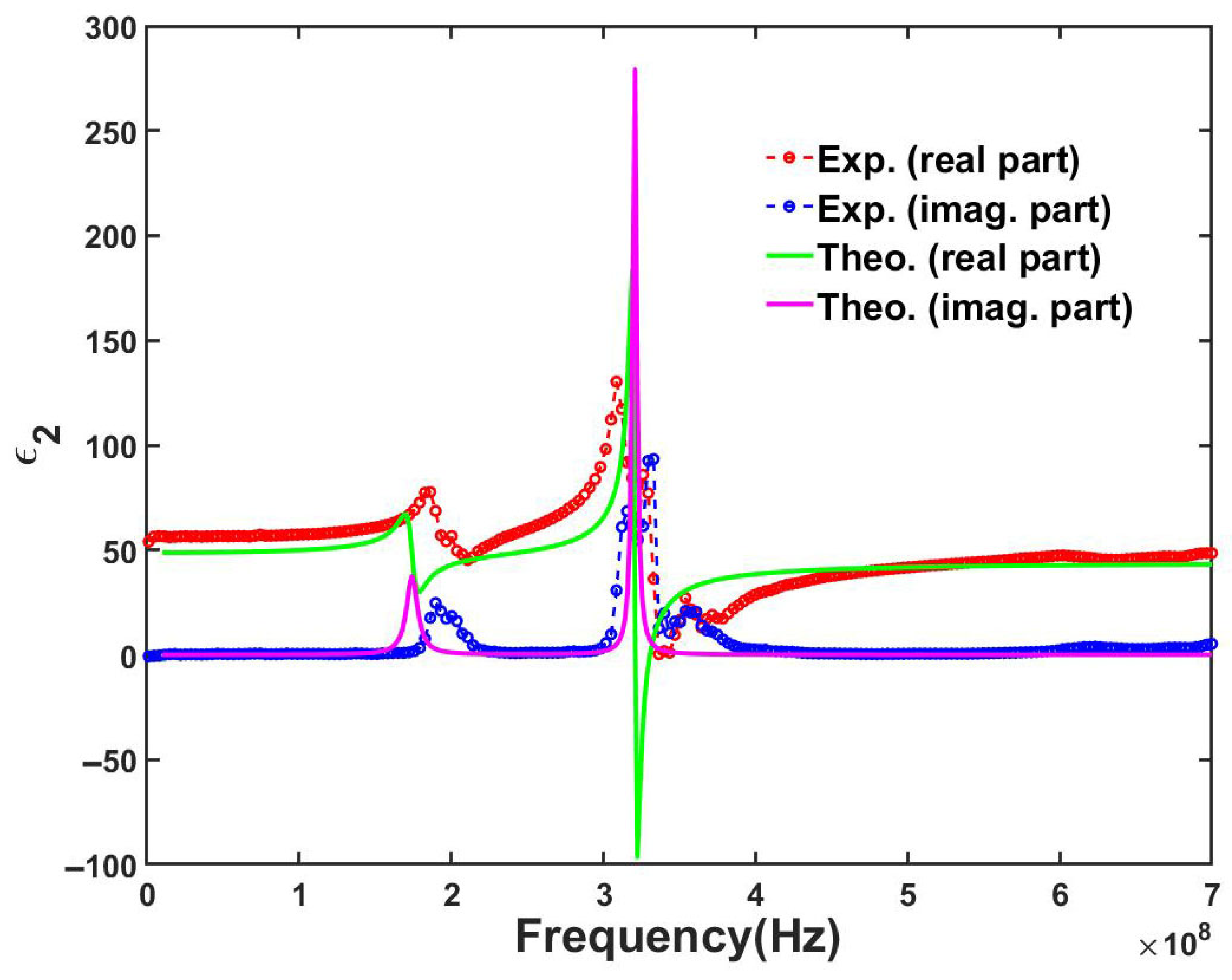
where and are the damping constants of pure TPP and LPP, respectively. In Figure 2, the calculated real and imaginary parts of the complex dielectric function of first-order PP are represented by green and purple solid lines, respectively. Here, the material constants of the congruent LiNbO3 crystal are selected from ref. [25]: , , = 2.50 C/m2, = 3.70 C/m2, , = 44.00. From the experimental data, the damping constants for pure TPP and LPP are set to 0.05 and 0.01, respectively. The correction factor k for the piezoelectric coefficient is determined as 0.3 based on the experimentally observed peak intensity of the pure transverse mode.
Figure 2.
Theoretically calculated and experimentally measured complex dielectric functions of the first-order pure TPP and LPP. The real and imaginary parts of the theoretical dielectric function are shown as green and purple solid lines, respectively. The experimental real and imaginary parts are represented by red and blue dashed lines with circle markers, respectively.
The complex dielectric function of the PPLN:Y:Mg in the y-direction was measured with a home-made nondestructive microstrip dual-resonator system [26]. A direct comparison between the measured data and theoretical predictions is presented in Figure 2. In Figure 2, the real and imaginary parts of the experimentally measured complex dielectric function of first-order PP are represented by red and blue dashed lines with circle markers, respectively.
As shown in Figure 2, both the theoretical and experimental complex dielectric function curves exhibit two dielectric anomaly peaks: the low-frequency peaks correspond to the pure TPP, while the high-frequency peaks correspond to the LPP. Previous studies have shown that transverse phonon-polaritons are generated by the coupling between transverse superlattice vibrations and EM waves, and that the strain associated with these transverse superlattice vibrations possesses a component along the periodic direction of the ferroelectric domains [4,5,6,7,8,9,10]. The theoretical model proposed in this paper demonstrates that even without this component, pure transverse superlattice vibrations can also couple with EM waves, giving rise to pure transverse phonon-polaritons. The experimental data successfully confirm the existence of the pure TPP. By comparing the experimental measurements with the theoretical simulation results, three main discrepancies are identified: (1) the intensities of the dielectric anomaly peaks are lower for the pure TPPs than for the LPPs; (2) the resonance frequency of the PP obtained from theoretical simulations is higher than the experimental value (see Table 1); (3) in the non-resonant region, the real part of the experimentally measured complex dielectric function is larger than the theoretically simulated value. The following section provides a detailed explanation of the above phenomena from the perspective of physical mechanisms.
Table 1.
The center frequency position for the polaritons. The data are taken from Figure 2.
The discrepancies in the dielectric anomaly peak intensity arise from the modulation of the PP coupling strength by the periodic structure and the finite transverse size of the crystal. For the longitudinal acoustic wave corresponding to S1, the direction of superlattice vibration is parallel to the direction of domain periodicity (x-axis). Under the first-order PP condition (where the acoustic wavelength equals the domain period), this mode satisfies the Bragg condition. Scattered waves from all domain walls undergo coherent constructive interference, forming a strong bulk resonance that couples efficiently with the electric field via the piezoelectric effect, resulting in a pronounced dielectric anomaly peak [4,5,6].
The pure transverse acoustic mode S4, which propagates along the x-direction, owes its propagation to the periodic modulation of the piezoelectric coefficients. However, due to the finite lateral dimensions of the sample, the energy of this mode becomes confined near the surfaces, and it exists primarily as surface acoustic waves. Consequently, the effective piezoelectric coupling volume is substantially smaller than that of the longitudinal S1 mode, which permeates the entire crystal. This leads to a significantly weaker coupling to the oscillating electric field of the EM wave, resulting in a faint dielectric anomaly peak in the measured spectrum. Theoretically, the intensity of this peak is modulated by the correction factor k introduced in Equation (2). The value k = 0.3 is determined by comparing the theoretical calculation with the experimentally observed peak intensity; when k = 0.3, the calculated peak amplitude closely matches the experimental data. The introduction of k allows the theoretical framework to self-consistently describe the weak coupling between the pure transverse acoustic wave and the electric field, thereby providing a quantitative account of the observed weak resonance peak signal.
As shown in Figure 2, the experimentally measured resonant frequencies of the first-order pure TPP and LPP are respectively higher than those of their theoretically simulated counterparts. The explicit and direct results of the center frequency position for the polariton are taken from Figure 2 and presented in Table 1. This shift is predominantly attributed to changes in the mechanical properties of the crystal induced by Mg doping. Mg incorporation significantly enhances the hardness of LiNbO3, manifested as an increase in the elastic stiffness constants C11 and C44, while also slightly reducing the material density ρ [27,28,29]. According to the resonant frequency formula, both the increase in elastic constants and the slight reduction in density contribute to the higher experimentally measured resonant frequency compared to the theoretical simulation, which was based on material parameters that did not account for doping-induced modifications.
In the non-resonant region, as shown in Figure 2, the experimentally measured real part of the dielectric function exceeds its theoretically simulated counterpart. This is mainly due to an additional polarization mechanism introduced by domain wall defects. In PPLN crystals grown by the Czochralski method, domain walls are often non-ideal, exhibiting tilts and meandering that increase the total domain wall area and defect density. At the domain walls, the abrupt reversal of spontaneous polarization leads to the accumulation of space charges, including both bound charges and free charges provided by defects, giving rise to significant interfacial polarization, also known as space-charge polarization [30,31,32,33]. This mechanism contributes additively to the dielectric function, causing the experimentally measured dielectric constant to be higher than the theoretical value.
4. Conclusions
We derived the dielectric function of a laterally bounded one-dimensional PSL, taking PPLN as a representative example. Experimentally, we measured the dielectric response of PPLN:Y:Mg. Since co-doping with Y and Mg does not alter the point group symmetry of the crystal, the measured dielectric function of PPLN:Y:Mg, particularly the observation of the dielectric anomaly, provides experimental validation for the existence of PPs predicted by our theoretical model. The measured dielectric function clearly revealed the existence of the pure TPP; however, three main systematic discrepancies between theory and experiment were observed. First, compared to the LPP, the dielectric anomaly peak corresponding to the pure TPP in the experiment was significantly weaker. Second, the experimental resonance frequency of the polariton was higher than the theoretical prediction. Finally, in the off-resonant region, the real part of the experimentally measured dielectric function was larger than the theoretical calculation. We provide corresponding physical explanations for these discrepancies. These include the modulation of the acoustic wave–electromagnetic wave coupling strength by the finite transverse size and periodic structure of the crystal; elastic constant hardening induced by MgO doping; and interfacial polarization effects arising from non-ideal domain walls and defects. This study not only deepens the understanding of acoustic wave–electromagnetic wave coupling mechanisms in bounded PSLs but also offers valuable insights for the design of ultrasonic and electromagnetic wave devices based on such materials.
Author Contributions
W.-C.B.: ideas; formulation or evolution of overarching research goals and aims; management and coordination responsibility for research activity planning and execution; designing computer programs; development or design of methodology. X.-Y.L.: development or design of methodology; creation of models; designing computer programs. X.-Y.H.: conducting the research and investigation process, data collection; programming. G.-X.L.: application of statistical, mathematical, computational, or other formal techniques to analyze or synthesize study data. B.-H.Z.: preparation, creation and/or presentation of the published work, specifically writing the initial draft (including substantive translation). G.T.: preparation, creation, and presentation of the published work, specifically writing the initial draft (including substantive translation). H.-Z.Z.: provision of study materials; management and coordination responsibility for research activity planning and execution. All authors have read and agreed to the published version of the manuscript.
Funding
This work is supported by Teaching Reform Research Project of Hunan Province of China (HNJG-2022-1009) and Scientific Research Fund of Hunan Provincial Education Department of China (25A0554).
Data Availability Statement
The original contributions presented in this study are included in the article. Further inquiries can be directed to the corresponding author.
Conflicts of Interest
The authors declare no conflict of interest.
References
- Huang, K. On the interaction between the radiation field and ionic crystals. Proc. R. Soc. Lond. Ser. A Math. Phys. Sci. 1951, 208, 352–365. [Google Scholar] [CrossRef] [Scilit]
- Hopfield, J.J. Theory of the contribution of excitons to the complex dielectric constant of crystals. Phys. Rev. 1958, 112, 1555–1567. [Google Scholar] [CrossRef] [Scilit]
- Henry, C.H.; Hopfield, J.J. Raman scattering by polaritons. Phys. Rev. Lett. 1965, 15, 964–966. [Google Scholar] [CrossRef] [Scilit]
- Bai, W.C.; Lan, Z.J.; Zhang, H.; Jiang, L. Theoretical investigation of the phonon-polariton mode in Czochralski grown piezoelectric superlattice. Superlattices Microstruct. 2016, 97, 167–175. [Google Scholar] [CrossRef] [Scilit]
- Bai, W.C.; Zhang, H.; Jiang, L.; Zhang, H.Z.; Zhang, L.Q. Theoretical investigation of phonon-polariton modes in undoped and ion-doped PPLN crystals. Solid State Commun. 2011, 151, 1261–1265. [Google Scholar] [CrossRef] [Scilit]
- Zhang, X.J.; Zhu, R.Q.; Zhao, J.; Chen, Y.-F.; Zhu, Y.-Y. Phonon-polariton dispersion and the polariton-based photonic band gap in piezoelectric superlattices. Phys. Rev. B 2004, 69, 428–433. [Google Scholar] [CrossRef] [Scilit]
- Huang, C.P.; Zhu, Y.Y. Piezoelectric-Induced Polariton Coupling in a Superlattice. Phys. Rev. Lett. 2005, 94, 117401. [Google Scholar] [CrossRef] [Scilit]
- Bai, W.C.; Li, B.H.; Zhou, B.H.; Zhao, D.; Lan, Z.-J.; Zhang, H.-Z.; Yuan, L. Transmission properties of electromagnetic waves in piezoelectric photonic crystal with periodically reversed ferroelectric domains. Solid State Commun. 2020, 324, 114143. [Google Scholar] [CrossRef] [Scilit]
- Bai, W.C.; Cao, Y.; Zhou, B.H.; Liu, J.-L.; Liu, G.-X.; Zhang, H.; Zhang, H.-Z.; Hu, H. Theoretical Investigation of Magneto-Electro-Elastic Piezoelectric Phononic Crystal. Crystals 2022, 12, 876. [Google Scholar] [CrossRef] [Scilit]
- Bai, W.-C.; Hu, H.; Zhou, B.-H.; Liu, G.-X.; Tang, G.; Huang, Y.-Y.; Cao, Y.; Zhang, H.; Zhang, H.-Z. Transmission Properties of Electromagnetic Waves in Magneto-Electro-Elastic Piezoelectric Electromagnetic Metamaterials. Symmetry 2022, 14, 1942. [Google Scholar] [CrossRef] [Scilit]
- Ma, W.; Hu, G.; Hu, D.; Chen, R.; Sun, T.; Zhang, X.; Dai, Q.; Zeng, Y.; Alù, A.; Qiu, C.-W. Ghost hyperbolic surface polaritons in bulk anisotropic crystals. Nature 2021, 596, 362–366. [Google Scholar] [CrossRef] [Scilit]
- Liu, L.; Xiong, L.; Wang, C.; Bai, Y.; Ma, W.; Wang, Y.; Li, P.; Li, G.; Wang, Q.J.; Garcia-Vidal, F.J. Long-range hyperbolic polaritons on a non-hyperbolic crystal surface. Nature 2025, 644, 76–82. [Google Scholar] [CrossRef] [Scilit]
- Zhang, S.; Ma, P.; You, O.; Zhou, S.; Feng, K.; Yuan, H.; Zhang, J.; Wu, C.; Luo, Y.; Yang, B. Phonon engineering enables hyperbolic asymptotic line polaritons. Nat. Nanotechnol. 2026, 21, 223–228. [Google Scholar] [CrossRef] [Scilit]
- Xu, J.; Yu, K.; Ni, X.; Renzi, E.M.; Zhou, L.; Yin, Y.; Zhou, Z.; Zhao, Z.; He, T.; Huang, D. Dynamic tuning of Bloch modes in anisotropic phonon polaritonic crystals. Light Sci. Appl. 2026, 15, 41. [Google Scholar] [CrossRef] [Scilit]
- Naumova, I.I.; Evlanova, N.F.; Blokhin, S.A.; Lavrishchev, S.V. Correlation between impurity distribution and location of ferroelectric domain walls in Nd:Mg:LiNbO3 single crystal. J. Cryst. Growth 1998, 187, 102–106. [Google Scholar] [CrossRef] [Scilit]
- Evlanova, N.F.; Naumova, I.I.; Chaplina, T.O.; Blokhin, S.A.; Lavrishchev, S.V. Periodically poled Y:LiNbO3 single crystal: Impurity distribution and domain wall location. J. Cryst. Growth 2001, 223, 156–160. [Google Scholar] [CrossRef] [Scilit]
- Sidorov, N.V.; Pikoul, O.Y.; Kruk, A.A.; Teplyakova, N.A.; Yanichev, A.A.; Palatnikov, M.N. Complex investigations of structural and optical homogeneities of low-photorefractivity lithium niobate crystals by the conoscopy and photoinduced and Raman light scattering methods. Opt. Spectrosc. 2015, 118, 259–268. [Google Scholar] [CrossRef] [Scilit]
- Pikoul, O.Y.; Sidorov, N.V.; Teplyakova, N.A.; Palatnikov, M.N. The laser conoscopy of lithium niobate crystals of different composition. In Asia-Pacific Conference on Fundamental Problems of Opto-and Microelectronics; SPIE: Bellingham, WA, USA, 2016. [Google Scholar]
- Sidorov, N.V.; Palatnikov, M.N.; Serebryakov, Y.A.; Lebedeva, E.L.; Kalinnikov, V.T. Effect of nonstoichiometry on the structure, properties, and Raman spectra of lithium niobate crystals. Inorg. Mater. 1997, 33, 419–427. [Google Scholar]
- Yatsenko, A.V. NMR study of Li-6 in LiNb0. Phys. Solid State 1998, 40, 109–111. [Google Scholar] [CrossRef] [Scilit]
- Wilkinson, A.P.; Cheetham, A.K.; Jarman, R.H. The defect structure of congruently melting lithium niobate. J. Appl. Phys. 1993, 74, 3080–3083. [Google Scholar] [CrossRef] [Scilit]
- Iyi, N.; Kitamura, K.; Yajima, Y.; Kimura, S.; Furukawa, Y.; Sato, M. Defect Structure Model of MgO-Doped LiNbO3. J. Solid State Chem. 1995, 118, 148. [Google Scholar] [CrossRef] [Scilit]
- Grabmaier, B.C.; Otto, F. Growth and investigation of MgO-doped LiNbO3. J. Cryst. Growth 1986, 79, 682. [Google Scholar] [CrossRef] [Scilit]
- Lu, Y. Preparation and Properties of Yttrium-Doped Lithium Niobate Crystals. Master’s Thesis, Harbin Institute of Technology, Harbin, China, 2014. [Google Scholar]
- Auld, B.A. Acoustic Fields and Waves in Solids; Wiley: New York, NY, USA, 1973. [Google Scholar]
- Tan, C.Y.; Chen, L.; Chong, K.B.; Ong, C.K. Nondestructive microwave permittivity characterization of ferroelectric thin film using microstrip dual resonator. Rev. Sci. Instrum. 2004, 75, 136–140. [Google Scholar] [CrossRef] [Scilit]
- Kushibiki, J.; Kobayashi, T.; Ishiji, H.; Chubachi, N. Elastic properties of 5 mol% MgO doped LiNbO3 crystals measured by line focus beam acoustic microscopy. Appl. Phys. Lett. 1992, 61, 2164–2166. [Google Scholar] [CrossRef] [Scilit]
- Xue, D.F.; He, X.K. Dopant occupancy and structural stability of doped lithium niobate crystals. Phys. Rev. B 2006, 73, 064113. [Google Scholar] [CrossRef] [Scilit]
- Kushibiki, J.; Kobayashi, T.; Ishiji, H.; Jen, C.K. Surface-acoustic-wave properties of MgO-doped LiNbO3 single crystals measured by line-focus-beam acoustic microscopy. J. Appl. Phys. 1999, 85, 7863. [Google Scholar] [CrossRef] [Scilit]
- Godau, C.; Kämpfe, T.; Thiessen, A.; Eng, L.M.; Haußmann, A. Enhancing the domain wall conductivity in lithium niobate single crystals. ACS Nano 2017, 11, 4816–4824. [Google Scholar] [CrossRef] [Scilit]
- Gonnissen, J.; Batuk, D.; Nataf, G.F.; Jones, L.; Abakumov, A.M.; Van Aert, S.; Schryvers, D.; Salje, E.K.H. Direct observation of ferroelectric domain walls in LiNbO3: Wall-meanders, kinks, and local electric charges. Adv. Funct. Mater. 2016, 26, 7599–7604. [Google Scholar] [CrossRef] [Scilit]
- Volk, T.; Gainutdinov, R.; Zhang, H.H. Domain patterning in ion-sliced LiNbO3 films by atomic force microscopy. Crystals 2017, 7, 137. [Google Scholar] [CrossRef] [Scilit]
- Lu, H.D.; Tan, Y.Z.; Mcconville, J.P.V.; Ahmadi, Z.; Wang, B.; Conroy, M.; Moore, K.; Bangert, U.; Shield, J.E.; Chen, L.; et al. Electrical tunability of domain wall conductivity in LiNbO3 thin films. Adv. Mater. 2019, 31, e1902890. [Google Scholar] [CrossRef] [Scilit] [PubMed]

Disclaimer/Publisher’s Note: The statements, opinions and data contained in all publications are solely those of the individual author(s) and contributor(s) and not of MDPI and/or the editor(s). MDPI and/or the editor(s) disclaim responsibility for any injury to people or property resulting from any ideas, methods, instructions or products referred to in the content. |
© 2026 by the authors. Licensee MDPI, Basel, Switzerland. This article is an open access article distributed under the terms and conditions of the Creative Commons Attribution (CC BY) license.