


Abstract
Truss-reinforced concrete composite slabs (TRCs) are extensively applied in prefabricated construction, but the limited stiffness of precast base plates may lead to excessive deformation and cracking during construction. This study investigates the truss-reinforced concrete composite slab with a single rectangular rib (TRC-SR) to improve flexural performance. A three-dimensional nonlinear finite element model was developed and verified through experimental results. The validated model was then used to compare the staged responses of TRCs and TRC-SRs and to evaluate the effects of rib height, rib width, precast base plate thickness, truss reinforcement diameter, and truss reinforcement height during the construction and service stages. The results show that the rectangular rib significantly enhances construction-stage stiffness under construction live load, and the maximum mid-span deflection decreases from 26.7 mm for TRC to 9.6 mm for TRC-SR, corresponding to a reduction of 64.0%, while plastic strain is also reduced and more localized. Rib height and precast base plate thickness are the dominant parameters governing construction-stage deformation, whereas the service-stage flexural performance is particularly sensitive to base plate thickness. A simplified method for calculating short-term flexural stiffness was further proposed based on transformed section theory and the average stiffness approach. For 12 parametric models, the mean ratio of finite element to theoretical deflection was 1.027, with a coefficient of variation of 7.57%. The results demonstrate the effectiveness of the rectangular rib in improving construction-stage flexural performance and provide useful references for the design optimization of TRC-SR precast base plates.
1. Introduction
Driven by the rapid advancement of prefabricated concrete construction, composite floor systems have been increasingly adopted because of their advantages in standardized production, construction efficiency, and reduced on-site formwork and wet operations. Among the various prefabricated floor systems, truss-reinforced concrete composite slabs (TRCs) have attracted considerable attention because the precast base plate can serve simultaneously as a permanent structural component and as formwork during construction, while the truss reinforcement contributes to stiffness and stability before the layer develops action. The construction method can reduce temporary formwork, simplify reinforcement installation, and facilitate industrialized building construction [1,2,3]. However, the precast base plate is relatively thin and must independently sustain its self-weight, construction loads, and the subsequently cast concrete during the construction stage. Consequently, the stiffness and cracking resistance may become critical design considerations, particularly as the slab span increases. Increasing the amount or dimensions of truss reinforcement can improve construction-stage stiffness but may also increase steel consumption and reduce the economic efficiency of the system. Therefore, improving the construction-stage mechanical performance of the precast base plate while maintaining material efficiency remains an important issue in the development of truss-reinforced composite floor systems.
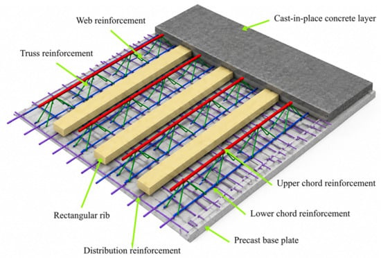
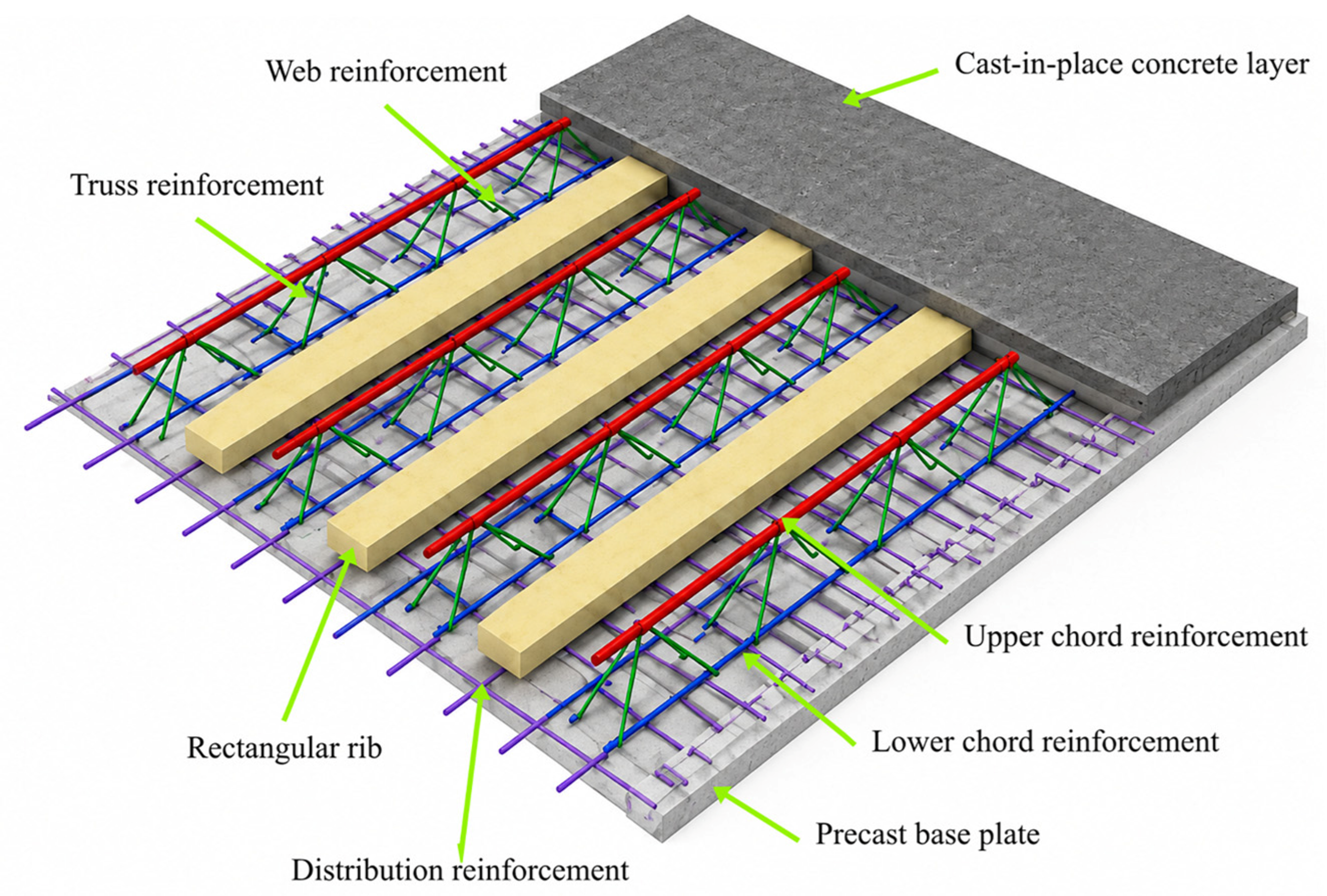
To address the limitations of TRCs, truss-reinforced composite slabs with rectangular concrete ribs have been developed by partially replacing conventional truss reinforcement with longitudinal concrete ribs integrated into the precast base plate. The introduction of rectangular rib increases the effective sectional depth of the precast component and can therefore enhance its flexural stiffness during construction without relying solely on additional truss reinforcement. Compared with conventional TRCs, the precast ribbed base plate exhibits adequate rigidity to act as working platforms during the construction stage, thus minimizing the demand for shoring system and labor [4]. In terms of load-transfer mechanism, the ribs within the prefabricated part function as concrete shear keys, working compositely with the cast-in-place overlay. Meanwhile, the overall integrity is guaranteed by mesh reinforcement located in the cast-in-place section [5]. Regarding construction efficiency, since the base plate is factory-made and only the top layer requires on-site casting, the schedule is shortened and costs are reduced [6]. The structural composition of the truss-reinforced composite slabs with rectangular concrete ribs is shown in Figure 1.
Figure 1.
Schematic diagram of truss-reinforced composite slabs with rectangular concrete ribs.
With the rapid development of prefabricated concrete structures, extensive research has been conducted worldwide on the interfacial composite action, structural configurations, material enhancement, and application of prestressing technology in composite slabs. The research focus has gradually shifted from early investigations of interfacial shear resistance and overall composite behavior toward lightweight design, high-performance materials, and multi-material composite systems.
The effectiveness of interaction is largely governed by the structural behavior of the interface between the two concrete layers. Early investigations mainly focused on interfacial roughness, reinforcement crossing the interface, and relative slip behavior. Subsequent studies explored the impact of surface roughness, processing methods, aggregate characteristics and bond strength on interfacial performance, consistently showing that improved surface roughness and bonding conditions enhance the composite interaction [7,8,9,10,11]. Ibrahim et al. [12] and Mohamed et al. [13] further explored the influence of interface moisture conditions and surface treatments on flexural behavior, shear resistance, and overall stiffness, and proposed corresponding experimental and numerical approaches. Beyond conventional concrete interfaces, Gholamhoseini et al. [14] developed an effective prediction model for full-scale experimental testing and analysis of the longitudinal shear strength. Chen and Shi [15] established a contact based finite element model incorporating adhesion and friction and validated its ability to estimate the load carrying performance through pull out and bending tests. Collectively, these studies have clarified the principal mechanisms governing interfacial load transfer and provided a solid theoretical and numerical basis for evaluating composite action.
Building on these studies, researchers have attempted to further improve the overall performance of composite slabs through structural innovation and material substitution. One research direction has focused on modifying the structural configuration to enhance load-transfer efficiency. Baran et al. [16] explored the composite effect of adding a in situ concrete topping to precast slabs and found that the topping substantially increased structural stiffness and cracking load, although its contribution to ultimate load-bearing capacity was relatively limited. Lee et al. [17] proposed a novel composite floor system, in which hollow concrete was combined with a profiled steel deck containing T-shaped ribs, resulting in favorable overall load-bearing performance. Al-Fakher et al. [18] strengthened precast hollow core slabs using a core reinforcement system (CRS) and demonstrated that the CRS could simultaneously provide internal support and function as additional reinforcement. Another research direction has been devoted to the application of lightweight and advanced materials to reduce structural self-weight while maintaining or improving mechanical performance. Yardim et al. [19] employed autoclaved aerated concrete as filling material in semi-precast slabs and documented that the dead load could be lowered by about 23–32% while delivering structural capacity comparable to that of conventional solid slabs. Mansour et al. [20] introduced steel-fiber-reinforced concrete to improve the ductility and cracking resistance. Joseph et al. [21] incorporated polystyrene cores into precast panels to reduce self-weight, whereas Sohel et al. [22] replaced conventional concrete with ultra-lightweight cementitious composites, resulting in improved capacity. Furthermore, novel materials and configurations such as recycled concrete, glass fiber reinforced bars, steel plates, and steel–timber composite systems have been introduced into composite floor structures, and the mechanical behavior has been thoroughly investigated through experimental and theoretical studies [23,24,25,26,27,28,29]. Overall, research on composite slabs has gradually evolved from simply increasing structural resistance toward lightweight construction, efficient material utilization, and coordinated improvement of multiple performance indicators.
Research specifically examining the staged flexural behavior of truss-reinforced composite slabs with rectangular concrete ribs has received less attention than studies on conventional reinforced concrete composite slabs and other rib-stiffened composite systems. Jakovljević et al. [30] conducted composite slab experiments and finite element parametric studies to examine how the angle between steel sheet ribs and steel beams affects the shear performance of headed shear connectors, and they proposed corresponding analytical expressions for the load-carrying performance. Yang et al. [31] proposed a novel double steel-concrete composite slab with stiffening ribs and connecting plates and investigated the influence of the stud spacing to plate thickness ratio on the buckling behavior of the face plates through two sets of bending tests. Soltanalipour et al. [32] demonstrated that open-rib profiles are prone to vertical separation between the concrete and steel sheet once interface slip initiates, a finding derived from their experimental and numerical investigation into the effect of profiled steel deck cross-sectional configuration on the longitudinal shear-slip response of steel-concrete composite slabs. Jiang et al. [33] investigated a high-ductility concrete composite slab with concrete ribs and truss reinforcement arranged beneath the ribs, and evaluated the effects of flange plates, truss configurations, and rib number on cracking resistance and short-term stiffness. Chen et al. [34] studied a lightweight ultra-thin ribbed precast truss base slab and examined the effects of rib height, rib width, and upper-chord reinforcement diameter on construction-stage short-term stiffness. Hoang et al. [35] investigated conventional reinforced concrete slabs strengthened with ultra-high-performance concrete overlays, with or without fiber-reinforced polymer reinforcement, and demonstrated significant improvements in flexural capacity. Although the previous studies have demonstrated the effectiveness of rib-type or sectional strengthening, existing investigations have mainly focused on lightweight ribbed precast slabs, specific rib configurations, or material enhancement strategies, whereas the present study further investigates the flexural behavior and stiffness evolution of TRC-SRs under different loading stages. The mechanical contribution of a single rectangular rib integrated into the conventional truss-reinforced composite slab, particularly its influence on flexural behavior during the construction and service stages, remains insufficiently understood.
In fact, the flexural performance of concrete composite slabs involves both the construction and service stages, with the construction stage being particularly critical [36]. Although previous studies have significantly improved the ultimate strength and overall performance through investigations of interface behavior, structural configurations, and advanced materials, existing research has explored the flexural resistance, shear capacity, and ultimate failure behavior of completed slabs [37,38,39]. In practical engineering, the construction of composite slabs involves positioning the reinforcement in the base plate and pouring concrete to form the prefabricated base plate. The base plate acts as a permanent formwork during the construction stage and becomes an integral part of the composite slab during the service stage. After curing, the prefabricated base plate is hoisted into place and simply supported on concrete beams at both ends. Subsequently, support reinforcement and additional reinforcement are installed before casting the composite layer. Prior to the cast-in-place concrete layer reaching its design strength, the prefabricated base plate independently bears all loads from the construction stage. Therefore, it is necessary to conduct separate flexural performance analyses for the construction stage and the service stage of composite slabs.
To address the insufficient understanding of the flexural behavior of truss-reinforced concrete composite slabs with rectangular ribs, this study focuses on TRC-SRs. A rectangular rib is introduced to enhance the sectional stiffness of the precast base plate and improve the flexural performance during construction, when the precast component must independently sustain the self-weight, construction load, and the weight of the cast-in-place concrete before composite action is fully developed. A single-rib configuration is adopted in this study to isolate the mechanical contribution of the rectangular rib and avoid the additional effects associated with rib number, spacing, and interaction among multiple ribs, thereby providing the clear basis for identifying the fundamental load-transfer and deformation mechanisms of the proposed system. First, a three-dimensional nonlinear finite element model is established and validated against experimental results. The validated model is then used to compare the construction-stage flexural behavior of conventional TRCs and TRC-SRs and to investigate the effects of rib height, rib width, precast base plate thickness, truss reinforcement diameter, and truss reinforcement height on the structural response during both the construction and service stages. Finally, based on transformed section theory and the average stiffness method, a simplified calculation method for the short-term flexural stiffness of the TRC-SR precast base plate during construction is proposed and the accuracy is verified through comparison with finite element analysis results.
2. Establishment and Validation of the Numerical Model
2.1. Geometric Model
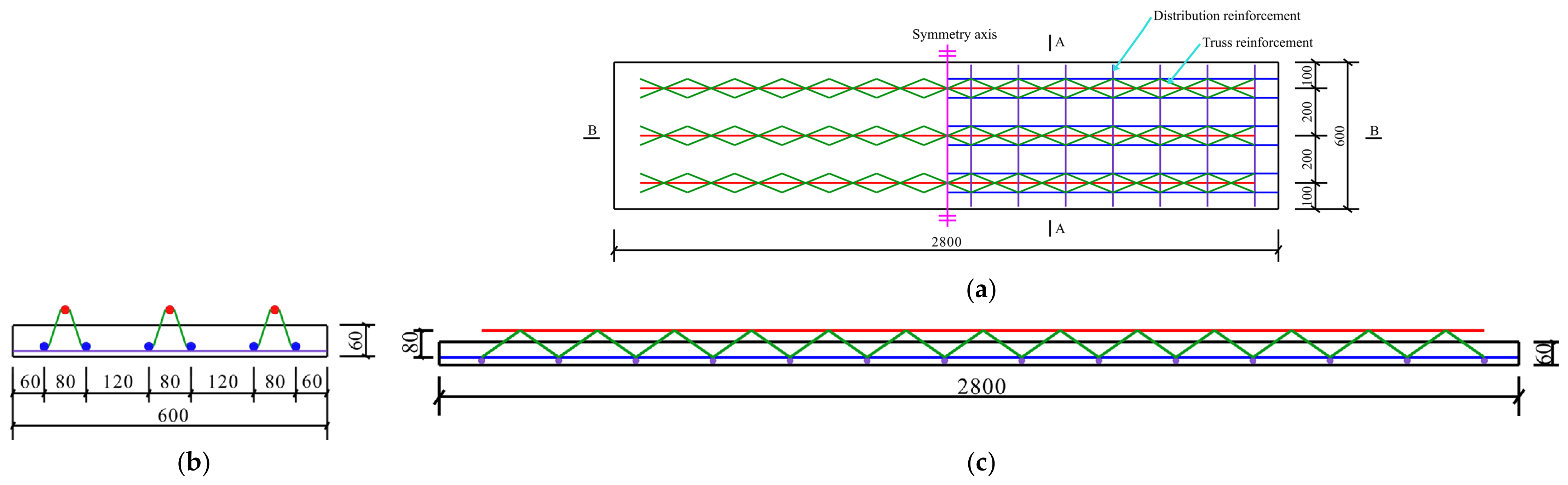
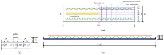
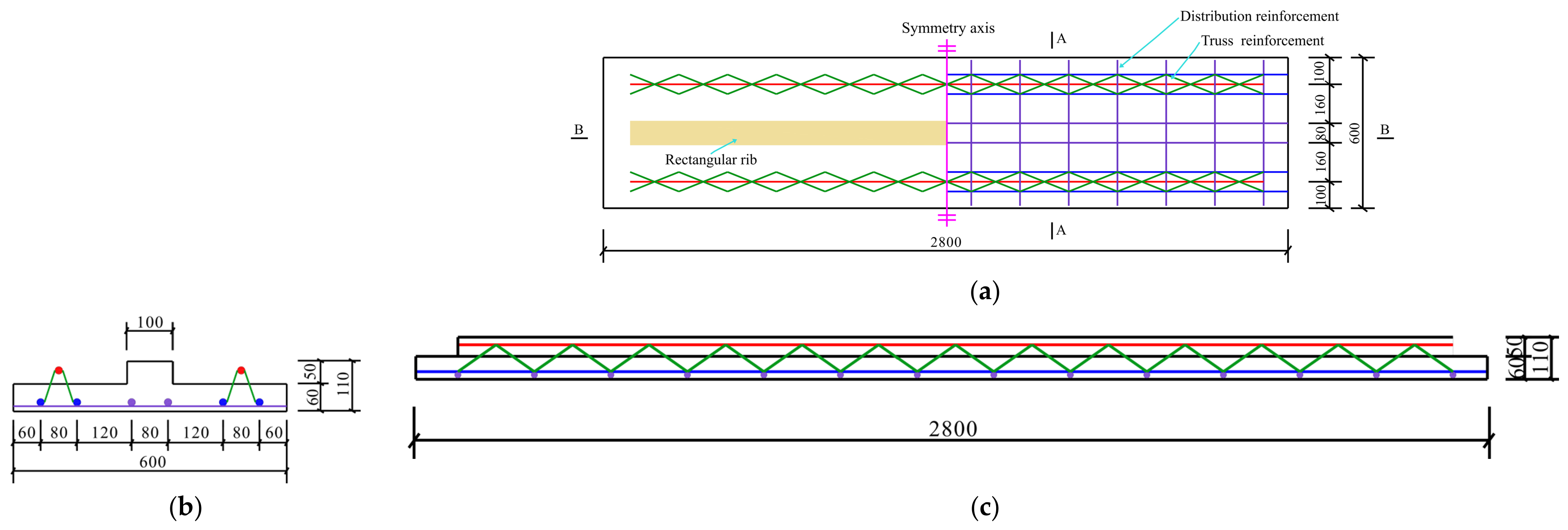
To validate the developed finite element model, specimens GHJ-1 and DLB-2 from the experimental study reported in reference [40] were adopted as representative validation cases for conventional TRCs and TRC-SRs, respectively. And the corresponding experimental results were used for comparison with the numerical predictions. Three-dimensional finite element models were subsequently established to perform the numerical analysis. And the numerical analysis results were compared against the experimental results for validation. Both specimens have an overall length of 2800 mm and a width of 600 mm. The total thickness of the composite slabs is 120 mm, comprising a 60 mm thick precast base plate and a 60 mm thick cast-in-place concrete layer. Specimen GHJ-1 is designed without rectangular ribs, whereas specimen DLB-2 features a single rectangular rib extending continuously along the longitudinal direction of the slab. The cross-sectional dimensions of the rectangular rib are 100 mm in width and 50 mm in height. The height and width of the truss reinforcement are both set to 80 mm. Both the upper and lower chords and the web members of the trusses are made of reinforcement with a diameter of 8 mm. The distribution reinforcement in the precast base plate has a diameter of 8 mm and a spacing of 200 mm. Figure 2 and Figure 3 present the geometric dimensions and reinforcement configurations of the base plate for specimens GHJ-1 and DLB-2, respectively. A half-sectional representation was adopted to illustrate the internal configuration of the base plate. The reinforcement arrangement after sectioning is shown on one side of the symmetry axis, whereas the unsectioned part is presented by the projected view on the other side. The symmetry axis indicates the longitudinal center of the slab and serves as the boundary between the two representations.
Figure 2.
Dimensions and reinforcement layout of the base plate of specimen GHJ-1: (a) plan view; (b) section A–A; (c) section B–B. (Unit: mm.)
Figure 3.
Dimensions and reinforcement layout of the base plate of specimen DLB-2: (a) plan view; (b) section A–A; (c) section B–B. (Unit: mm.)
2.2. Establishment of Finite Element Model
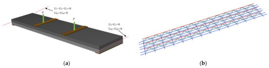
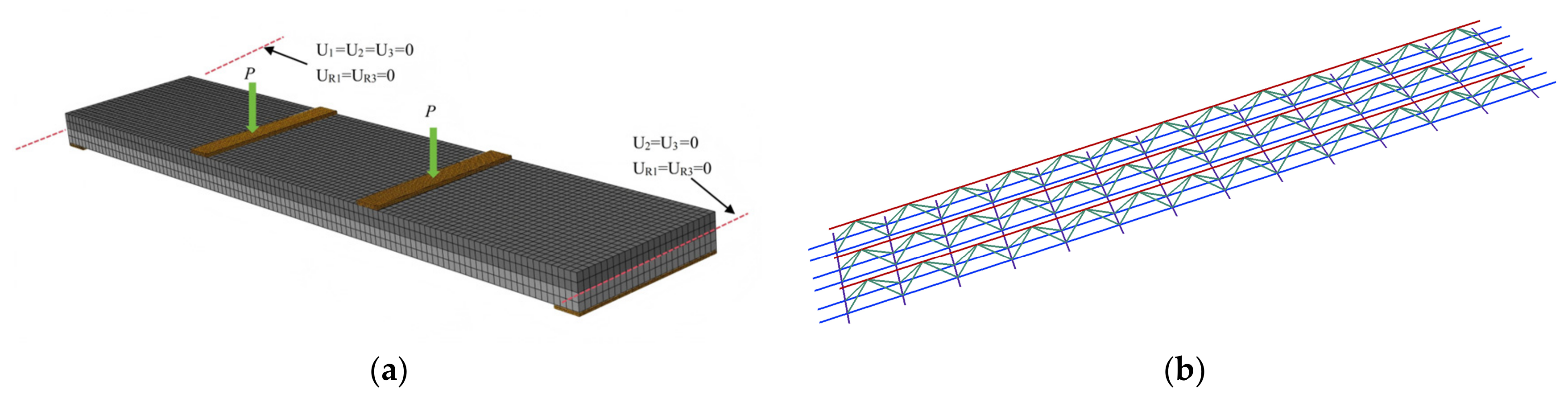
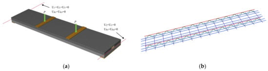
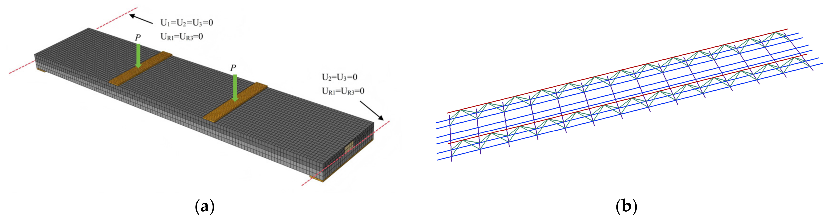
The three-dimensional nonlinear finite element model for the composite slab was developed utilizing finite element analysis program ABAQUS 2024. Figure 4 and Figure 5 present the finite element model of the composite slabs for specimens GHJ-1 and DLB-2, respectively. To clearly illustrate the internal configuration of the concrete rib, the two ends of the finite element model of the TRC-SR were partially sectioned for visualization, thereby exposing the rectangular concrete rib. The sectional treatment was applied only for visualization and did not affect the actual geometry or numerical analysis.
Figure 4.
The finite element model of the specimen GHJ-1: (a) analysis model; (b) reinforcement framework.
Figure 5.
The finite element model of the specimen DLB-2: (a) analysis model; (b) reinforcement framework.
According to the geometric characteristics and main stress forms of each component of the composite plate, appropriate element types are selected for concrete, distribution reinforcement, and truss reinforcement. The concrete was simulated by the three-dimensional eight-node linear reduced integral solid element C3D8R. C3D8R simulates mechanical behavior under a three-dimensional stress state and incorporates nonlinear material constitutive models to capture phenomena such as concrete cracking, compression plasticity, and stiffness degradation. The distribution reinforcement and truss reinforcement have obvious characteristics of slender members, which are mainly subjected to axial tension and compression. Therefore, the two-node truss element T3D2 was used for simulation.
The embedded region constraint in ABAQUS was employed to model the bond between reinforcement and the surrounding matrix. After adopting the constraint, the displacement of the embedded reinforcement node is determined by interpolation of the displacement of the concrete solid element where it is located, so as to maintain deformation coordination between the reinforcement and the surrounding concrete. The surface-to-surface contact with normal hard behavior was applied at the precast base plate and cast-in-place concrete interface, permitting tensile separation but prohibiting compressive interpenetration. Tangentially, a friction coefficient of 0.6 was assigned to capture the interfacial bond-slip response [6]. A sensitivity analysis was conducted using friction coefficients of μ = 0.4, 0.6, and 0.8. The resulting peak loads showed only minor variation, and the overall load–deflection responses and comparative conclusions between TRC and TRC-SR remained essentially unchanged. Relative slip initiates when the equivalent shear stress reaches the critical value defined as the product of the friction coefficient and the normal contact pressure, and a small amount of reversible elastic slip is permitted during the sticking phase to facilitate numerical convergence.
The finite element mesh size not only affects the computational accuracy but also directly influences computational efficiency and convergence of the nonlinear analysis. For nonlinear analysis of concrete, an overly coarse mesh may inadequately resolve localized stress gradients and damage progression, whereas an excessively fine mesh would significantly increase the computational cost and potentially reduce the convergence efficiency once the material enters the nonlinear stage. Considering both accuracy and efficiency, a uniform mesh size of 25 mm was adopted for the precast base plate and cast-in-place layer, while a finer 10 mm mesh was assigned to the distribution and truss reinforcement to ensure that the stress distribution of the reinforcement and the variation along the longitudinal direction can be adequately captured. A mesh sensitivity analysis was further conducted based on specimen DLB-2. Three mesh densities with concrete element sizes of 40 mm, 25 mm, and 15 mm were established under identical modeling conditions. The corresponding mid-span deflections were 18.76 mm, 18.42 mm, and 18.31 mm, respectively. The difference between the 25 mm and 15 mm mesh models was only 0.60%, indicating that the numerical results were essentially mesh independent. Therefore, a mesh size of 25 mm was adopted for the concrete components considering the balance between computational accuracy and efficiency.
The composite slab is loaded under a four-point bending configuration. The vertical load was applied via four-point bending, with two loading points acting synchronously and the load increased in incremental steps to capture the full process mechanical response of the structure. To prevent significant stress concentrations in the local concrete regions caused by concentrated loads and support reactions, rigid bearing plates were installed above both loading points and below both supports. The dimensions of the bearing plates are 600 mm × 100 mm × 12 mm. A pin boundary condition was imposed at the left end, fully restraining its translational degrees of freedom. However, a roller boundary condition was imposed at the right end, permitting longitudinal displacement along the span direction and restraining vertical translation. Both ends were only permitted to rotate freely about the Y-axis. To mitigate stress concentrations that would otherwise arise from the concentrated loads and support reactions, rigid loading plates were placed above the beneath the supports. The rigid plates were tied to the corresponding surfaces of the composite slab using tie constraints, which enforce displacement compatibility between the master and slave surfaces throughout the analysis, thereby neglecting any potential bond slip effect at the plate to slab interfaces.
2.3. Material Properties
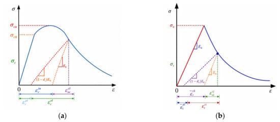
To accurately simulate the material nonlinear behavior of composite slabs during construction and service loading induced by concrete cracking, compression nonlinearity and stiffness degradation, it is essential to incorporate an appropriate constitutive model for concrete. Nie and Wang [41] demonstrated that numerical results obtained by employing the Concrete Damaged Plasticity (CDP) model agree well with experimental data. Building on this, this study adopts the CDP model proposed by Lee and Fenves [42]. The model has been appropriately modified according to actual engineering conditions to more accurately describe the nonlinear mechanical response of concrete under complex stress states. Furthermore, by independently defining tensile and compressive damage variables, it effectively captures the distinct mechanical behaviors of concrete. Consequently, it is particularly suitable for simulating the mechanical behavior of flexural members and exhibits robust convergence during iterative solution procedures [43,44,45]. The uniaxial compressive stress–strain response of concrete is divided into three distinct stages. The uniaxial tensile and compressive stress–strain behaviors of concrete are illustrated in Figure 6.
Figure 6.
Uniaxial tensile and compressive stress–strain curves of concrete: (a) compressive strengthening curve; (b) tensile strengthening curve.
For uniaxial compression, the CDP model defines the stress–strain relationship as a piecewise function that comprises a linear elastic branch, a hardening branch up to the peak stress, and a post-peak softening branch. The explicit formulation is given as follows:
where σc is the compressive stress of concrete, ε is the compressive strain of concrete, E0 is the initial elastic modulus of concrete, fck is the peak compressive strength of concrete, εck is the strain corresponding to the peak compressive stress, αa is the shape parameter of the ascending branch, αc is the shape parameter of the descending branch.
In the CDP model, the uniaxial tensile behavior of concrete comprises an elastic ascending branch followed by a softening branch, which can be described by the following piecewise formulation:
where σt is the uniaxial tensile stress of concrete, ftk is the standard value of concrete uniaxial tensile strength, εtk is the tensile strain corresponding to the peak tensile stress, and αt is the shape parameter for the descending branch.
During the damage evolution phase, the propagation of internal micro-defects within the material, thereby causing a degradation of the macroscopic elastic modulus. Based on the strain equivalence principle proposed by Lemaitre [46], the constitutive relationship between the damaged effective elastic modulus E and the initial undamaged elastic modulus E0 can be characterized by a reduction via the damage factor, which is specifically expressed as
where d is the damage factor (0 ≤ d ≤ 1); d = 0 represents the undamaged initial state of the material, while d approaching 1.0 indicates a complete loss of material stiffness.
When employing finite element software to capture the nonlinear compressive response, the accurate definition of the material inelastic deformation is a fundamental prerequisite for ensuring both the numerical convergence and the computational accuracy of the model. Under compression, the CDP model requires the inelastic strain as the governing parameter for defining the hardening or softening curve. From the perspective of continuum damage mechanics, the inelastic strain characterizes the total accumulated irreversible deformation together with the damage-induced additional deformation of concrete during uniaxial compression, after excluding the ideal linear elastic response. The specific definition is expressed as
where is the inelastic strain, is the undamaged elastic strain, is the equivalent plastic strain, and dc is the compressive damage factor.
In practical finite element analysis, it is essential to input the true stress, as well as the corresponding cracking strain and the associated damage factors. For tensile behavior, the cracking strain is expressed as follows:
where is the cracking strain, is the true elastic strain, is the equivalent plastic strain, and dt is the tensile damage factor.
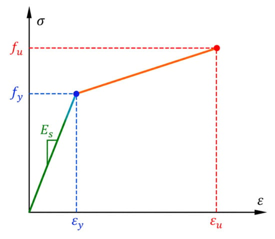
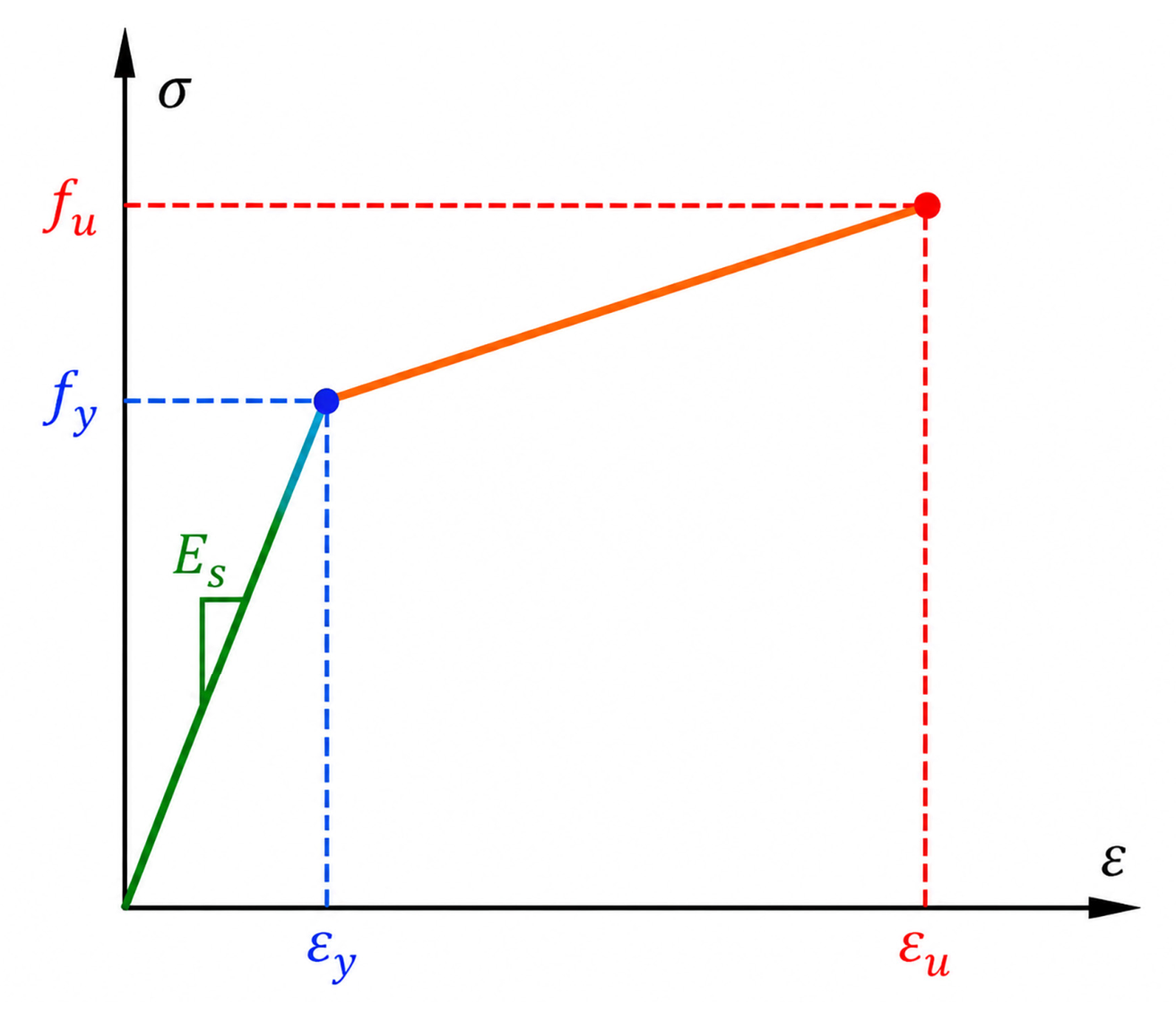
A bilinear model was adopted to capture the stress–strain relationship of reinforcement, as shown in Equation (8). This model consists of an elastic branch and a strain-hardening branch, which adequately captures hardening behavior of reinforcement while maintaining simplicity in parameter calibration and computational cost. For composite slabs primarily subjected to flexure and shear, the bilinear model provides sufficient accuracy in predicting ultimate strength and deformation, and it avoids convergence difficulties associated with more complex hardening laws, making it a common choice in nonlinear structural analyses. The stress–strain relationship curve of the reinforcement is shown in Figure 7.
where Es denotes the elastic modulus of the steel reinforcement, fy and εy represent, respectively, the yield strength and yield strain of the steel reinforcement, and k represents the strain-hardening slope of the strengthening segment in the stress–strain curve. In this study, HRB400 reinforcement was adopted, and the strain-hardening slope k was set to 2000 MPa.
Figure 7.
The stress–strain relationship curve of the reinforcement.
In this study, C30 concrete was used for the precast base plate and cast-in-place concrete layer. The basic mechanical properties of C30 concrete are summarized in Table 1, while the nonlinear stress–strain and damage evolution parameters used for the CDP model are provided in Table 2. The data listed in Table 2 represent typical discrete stress–strain and damage points used to characterize the nonlinear response of concrete in the CDP model. The axial compressive strength fck = 20.1 MPa and tensile strength ftk = 2.01 MPa listed in Table 1 represent the standard strength values adopted for C30 concrete. In contrast, the peak compressive and tensile stresses of 21.15 MPa and 2.43 MPa listed in Table 2 represent the constitutive stress values used to define the nonlinear stress–strain relationships in the CDP model. Plastic damage model parameters for C30 were defined by setting the dilation angle ψ to 31.35°, the flow potential eccentricity ζ to 0.1, and the ratio of biaxial to uniaxial compressive strength fb0/fc0 to 1.16. Additionally, the ratio of tensile meridian stress to compressive meridian stress K was assigned a value of 0.6667, while the viscosity parameter μ was taken as 0.005. The selection of the CDP parameters was based on the mechanical characteristics of C30 concrete and the recommended ranges for normal strength concrete reported in previous nonlinear finite element studies. The dilation angle ψ was selected to represent the plastic volumetric expansion behavior of concrete, while ζ, fb0/fc0, and K were adopted to describe the multiaxial strength characteristics of concrete. The viscosity parameter μ was assigned a relatively small value to improve numerical convergence without significantly affecting the structural response. The overall suitability of the adopted parameter set was further evaluated at the structural level through comparison with the experimental flexural results. The reinforcement adopts HRB400 hot-rolled ribbed bars. The yield strength standard value fyk is 400 MPa, and the elastic modulus ES is 2 × 10⁵ MPa.
Table 1.
Material properties of C30.
Table 2.
Relevant plastic damage parameters of C30.
2.4. Verification of the Finite Element Model
2.4.1. Comparison of Load and Deflection Relationships
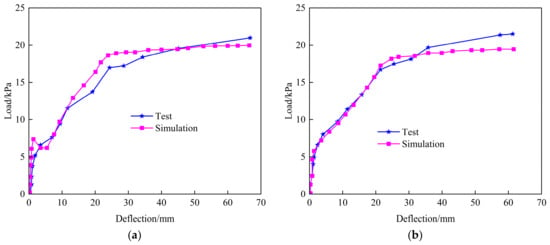
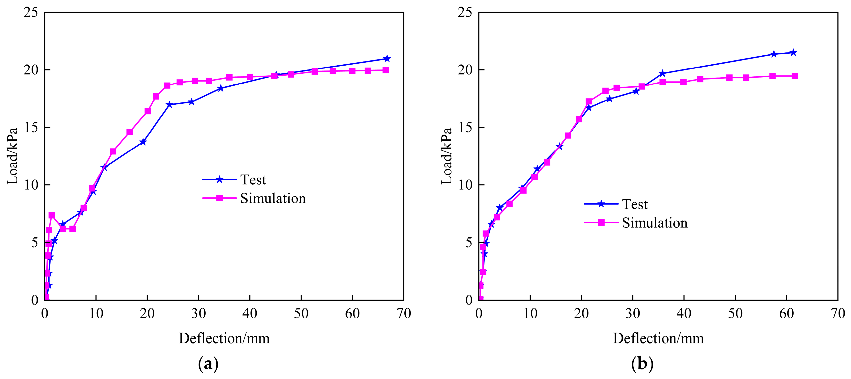
The load–mid-span deflection curve is a key macroscopic indicator that reflects the overall stiffness degradation, cracking, and yielding characteristics during the entire flexural process. To verify the validity of the finite element model, the simulation results of specimens GHJ-1 and DLB-2 are compared with the experimental results. The load–deflection curves were plotted by extracting the reaction forces at the loading points and the mid-span deflection, as shown in Figure 8.
Figure 8.
The mid-span deflection–load curves of test and simulation: (a) specimen GHJ-1; (b) specimen DLB-2.
As shown in Figure 8, for specimen GHJ-1, the experimental curve shows a pronounced change in slope at approximately 17.3 kPa, indicating the onset of yielding. The corresponding yield load predicted by the finite element model is 18.5 kPa, only 6.9% higher than the experimental value. The ultimate load obtained from the test and simulation are approximately 21.6 kPa and 20.8 kPa, respectively, with a deviation of 3.7%. The results indicate that the model provides a reasonable prediction of both the yielding behavior and ultimate load-carrying capacity of GHJ-1. For specimen DLB-2, significant nonlinear behavior develops after the experimental load reaches approximately 17.2 kPa. The simulated yield load is 18.1 kPa, corresponding to a deviation of 5.2%. The experimental ultimate load reaches 21.5 kPa, whereas the simulated value is approximately 19.4 kPa, which is 9.8% lower. The relatively larger deviation in the ultimate load of DLB-2 may be associated with idealizations in the material constitutive models, interaction between reinforcement and concrete, and interfacial contact treatment, as well as the omission of specimen-level variability in material properties and geometry. These effects become more influential near the ultimate state, where localized cracking and nonlinear damage development increasingly govern the structural response. The model can reasonably capture the overall nonlinear response and load-carrying capacity of DLB-2.
Overall, the simulated load–deflection curves of GHJ-1 and DLB-2 agree well with the experimental results. Both the experimental and numerical curves exhibit an approximately linear response at the initial loading stage, followed by stiffness degradation after cracking and accelerated deformation at higher load level. The discrepancies in the yield and ultimate load remain within 10%.
2.4.2. Comparison of Cracking Loads
The cracking load is a key indicator for evaluating whether the established model can accurately characterize tensile damage evolution and stiffness degradation process of concrete. To further validate the rationality of the model, this study compares experimentally measured cracking loads of specimens GHJ-1 and DLB-2 with numerical predictions. In the concrete plastic damage model, there are multiple criteria for determining the cracking direction. Initial cracks occur in regions where the maximum principal plastic strain is positive [47]. Based on this theory, the simulated cracking load was observed by extracting plastic strain contour plots in finite element model. Figure 9 illustrates the plastic strain contour plots for specimens GHJ-1 and DLB-2.
Figure 9.
The plastic strain contour plots of the composite slab: (a) specimen GHJ-1; (b) specimen DLB-2.
As can be seen from Figure 9, the maximum principal plastic strains of specimens GHJ-1 and DLB-2 are primarily concentrated in the mid-span, while the plastic strains near the slab ends and supports remain relatively small. The findings suggest that initial tensile damage in both specimens occurs first in the mid-span region where the bending moment is relatively large, which is consistent with the theoretical mechanical characteristics of composite slabs under four-point bending. The maximum principal plastic strain of GHJ-1 is mainly distributed over a relatively large area in the mid-span, with obvious strain concentration formed in localized regions. Similarly, the plastic strain of DLB-2 is also concentrated in the mid-span region, but the local strain concentration is even more pronounced. The maximum principal plastic strain initiates from zero and gradually propagates to the surrounding areas. Therefore, this study defines the load corresponding to the initial occurrence of significant positive maximum principal plastic strain in the mid-span tension zone as the simulated cracking load.
Following the criterion, the maximum principal plastic strain in the cracked region was extracted during the finite element post-processing, serving as the criterion for determining the simulated cracking load. A comparison was conducted between the numerical results and the tested cracking load, and the results are compiled in Table 3.
Table 3.
Comparison of experimental and simulated cracking load.
Table 3 illustrates that the simulated cracking loads for specimens GHJ-1 and DLB-2 align well with the tested values. The relative errors for the cracking loads of both specimen groups are well within the acceptable range for engineering applications, indicating that the finite element model can reasonably capture the plastic mechanical behavior of the investigated composite slabs.
In summary, the good agreement between the numerical predictions and experimental results demonstrates that the established finite element model can effectively capture the nonlinear flexural behavior of the composite slabs. The consistency in the overall structural response further verifies the rationality of the adopted modeling strategy. Although the geometries adopted in the subsequent parametric analyses differ from those of the validation specimens, the same material models, element formulations, interaction definitions, and numerical modeling framework are consistently employed. On this basis, the validated modeling framework is extended to the parametric models to investigate comparative trends and parameter sensitivities within the investigated range. The resulting comparisons are therefore interpreted primarily in terms of relative structural responses rather than as direct experimental validation of each specific parametric geometry.
3. Flexural Performance Analysis of TRC-SRs
3.1. Analysis Model and Loading Procedure
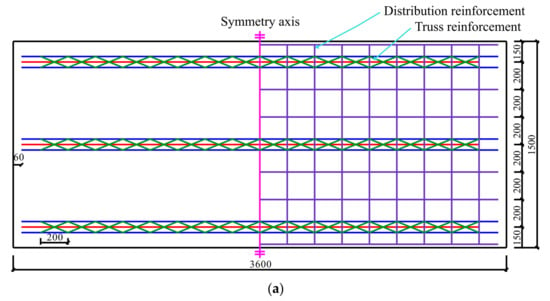
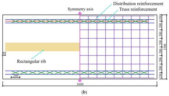
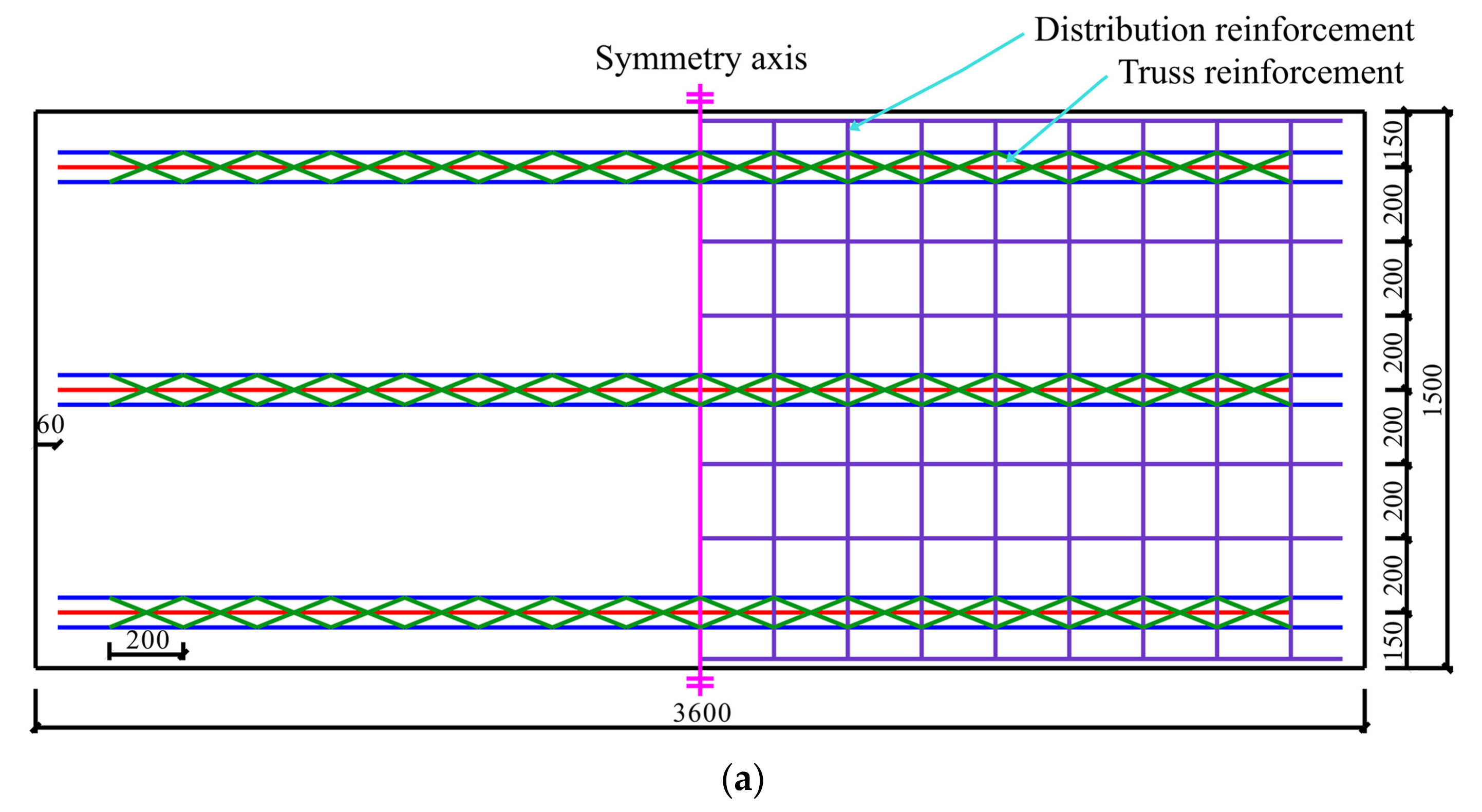
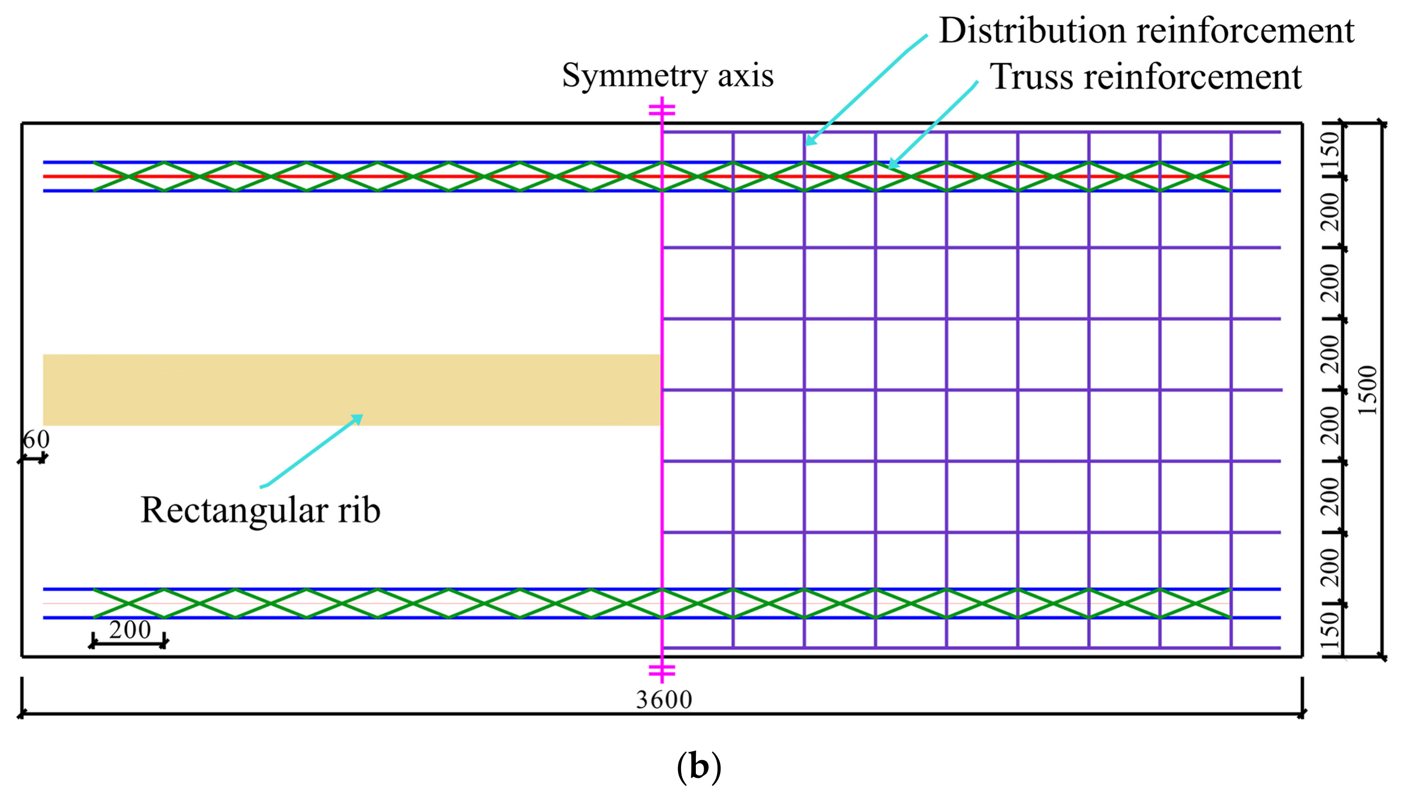
Given that the structural differences between TRCs and TRC-SRs are primarily reflected in the load-bearing performance during the construction stage, a comparative study was conducted on the prefabricated base plate prior to the casting of the concrete layer to evaluate the flexural performance of both systems during the construction stage. A typical TRC base plate with a span of 3600 mm, a width of 1500 mm, and a thickness of 60 mm was selected as the analytical object. Subsequently, keeping the span and cross-sectional dimensions of the base plate unchanged, the truss reinforcement in the middle of the base plate is replaced by a rectangular concrete rib with a cross-section of 200 mm × 50 mm, thereby forming the TRC-SR base plate. The geometric parameters and reinforcement configurations of the precast base plate are shown in Figure 10.
Figure 10.
The geometric parameters and reinforcement configurations of the composite slab base plate: (a) TRC; (b) TRC-SR.
Due to the secondary loading effect during the construction process, the mechanical behavior is relatively complex. To more accurately simulate the actual construction conditions, a total of four analysis steps were set up in the numerical simulation to apply the loads sequentially, including self-weight, construction live load, and the gravity of the cast-in-place concrete layer. It was taken as the maximum standard value of 1.5 kPa with reference to [48].
To reproduce the sequential mechanical response of the precast base plate during construction, a staged loading procedure was adopted in the quasi-static finite element analysis, where the time period of each step was normalized to unity as a dimensionless pseudo-time parameter rather than the actual construction duration. For convenient presentation of the complete loading history, four consecutive analysis steps were set up to control the step-by-step transition of different construction load cases, expressed using a cumulative normalized pseudo-time ranging from 0 to 4. An initial analysis step and four consecutive loading steps were established to consider the application, maintenance, and unloading effects during the construction process. In the initial step, simply supported boundary conditions were applied to the precast base plate to establish the model constraints and determine the initial equilibrium state. Subsequently, the self-weight load of the precast base plate was applied in Step 1 (pseudo-time ranging from 0 to 1) to simulate the initial mechanical state after the component was hoisted into place. In Step 2 (pseudo-time ranging from 1 to 2), a construction live load with a standard value of 1.5 kPa was applied to simulate the actual mechanical state under the action of construction personnel, equipment, and temporary surcharges. In Step 3 (pseudo-time ranging from 2 to 3), the construction live load was removed to evaluate the unloading response after temporary construction activities. It should be noted that the step is introduced to separate the effect of construction live load from the subsequent loading stage and does not imply that all temporary loads are necessarily absent during actual concrete placement. Finally, in Step 4 (pseudo-time ranging from 3 to 4), the self-weight load of the cast-in-place concrete layer was applied to evaluate the structural response after concrete casting. After the completion of the construction stage simulation, the final structural state was retained for the subsequent service stage analysis. The residual deflection and concrete damage accumulated during the construction stage were continuously transferred to the service stage analysis.
The adopted loading sequence aims to separately investigate the influence of different construction-stage loads on the flexural behavior of TRC-SR precast base plates. Although construction live load and wet concrete weight may coexist during practical casting operations, the present study focuses on the comparative evaluation between TRCs and TRC-SRs under representative construction stages. In actual construction, construction personnel, equipment, and freshly placed concrete may act simultaneously. Therefore, the evaluation of construction safety for specific projects should consider the corresponding unfavorable load combinations based on actual construction procedures, site conditions, and applicable design requirements.
3.2. Analysis of Comparison Results
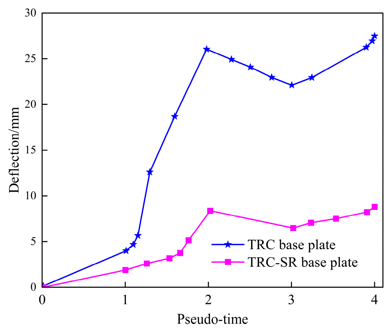
To systematically evaluate the influence of different structural configurations on the flexural performance of the precast base plates during the construction stage, the finite element analysis was conducted. The relationship curves between the mid-span deflection of the two composite slab base plates and the analysis step size are presented in Figure 11.
Figure 11.
The relationship curves between pseudo-time and deflection.
As observed in Figure 11 that TRC and TRC-SR exhibit similar deflection development trends during staged construction loading. Under self-weight in Step-1, both specimens show relatively small deflection increases. In Step-2, the construction live load causes a pronounced increase in deflection, with the TRC base plate reaching 26.7 mm, whereas the TRC-SR base plate reaches only 9.6 mm, representing a reduction of 64.0%. After unloading in Step 3, both specimens exhibit partial elastic recovery but retain residual deformation. In Step 4, the deflection increases again under the self-weight of the cast-in-place concrete, while the TRC-SR consistently maintains a much lower deformation level. The results indicate that the rectangular concrete rib significantly enhances the flexural stiffness of the precast base plate and effectively suppresses construction-stage deformation. This improvement is primarily attributed to the increase in effective sectional depth and moment of inertia introduced by the rib. Compared with the conventional flat precast plate, the rib provides additional compression and tensile force transfer paths, thereby reducing the bending curvature under construction loads. Meanwhile, the rib improves the local stress distribution within the section, which delays tensile damage accumulation and limits the development of plastic strain in the mid-span region.
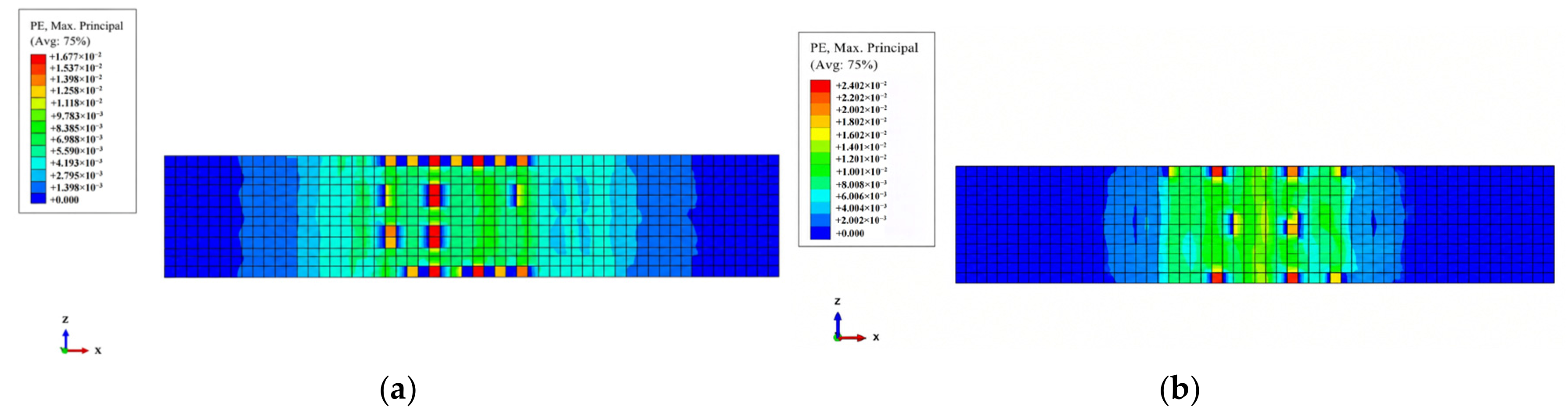
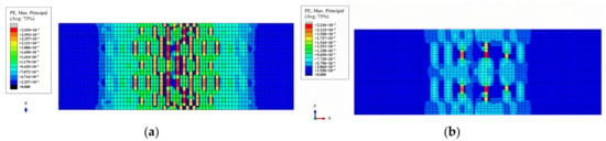
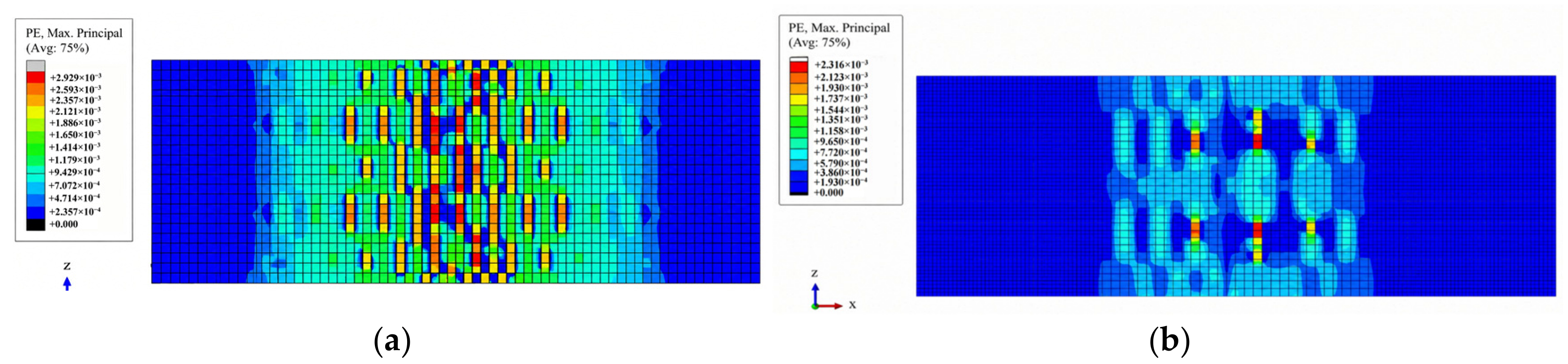
To further reveal the cracking and damage evolution characteristics of the two types of precast base plates during the construction stage, and to evaluate the influence of different structural configurations on concrete damage development from the perspective of local mechanical response, the plastic strain distribution contours of both precast base plates are presented in Figure 12.
Figure 12.
The maximum plastic strain contour of the base plates: (a) TRC; (b) TRC-SR.
As depicted in Figure 12, the plastic strains of both precast base plates are mainly concentrated in the midspan tensile zone, indicating that tensile cracking initiates in the region of high bending moment. However, the strain distributions differ significantly. For the conventional TRC, the maximum principal plastic strain reaches approximately 2.9 × 10⁻³, with continuous high-strain bands distributed over a relatively large area, indicating pronounced tensile cracking and damage development. In contrast, the TRC-SR exhibits a lower maximum plastic strain of approximately 2.3 × 10⁻³, and the high-strain regions are confined to localized areas. This demonstrates that the rectangular concrete rib effectively limits plastic deformation and crack propagation. The rib modifies the internal load-transfer path, enhances the flexural stiffness and moment of inertia of the section, and reduces stress concentration in the tensile zone. Consequently, the TRC-SR exhibits both a lower peak plastic strain and a smaller damage zone under construction load.
Considering the deflection response and plastic strain distribution, the rectangular concrete rib significantly enhances the mechanical performance of the precast base plate during construction. By increasing the sectional stiffness, the rib effectively reduces overall deformation while alleviating plastic strain concentration in the tensile zone, thereby restraining crack propagation and local damage accumulation. As a result, the TRC-SR base plate exhibits improved cracking resistance and deformation control under construction load.
3.3. Influence of Key Parameters on the Flexural Performance of TRC-SR
3.3.1. Parametric Design and Numerical Results
The flexural performance of the TRC-SR is primarily determined by the cross-sectional stiffness of the precast base plate during the construction stage and the overall flexural performance during the service stage after composite action is achieved. To systematically examine the effects of multiple variables on the performance of the precast base plate during the construction stage and the overall structural performance during the service stage, a parametric analysis was conducted based on the baseline model. Five key parameters with representative effects on the flexural performance were selected as variables. During the parametric analysis, all parameters except the investigated variable were kept identical to those of the baseline model S1. The geometric dimensions of all specimens remained unchanged, with a slab span of 3600 mm and a slab width of 1500 mm. The basic parameters of each model are presented in Table 4.
Table 4.
Basic design parameters of the models.
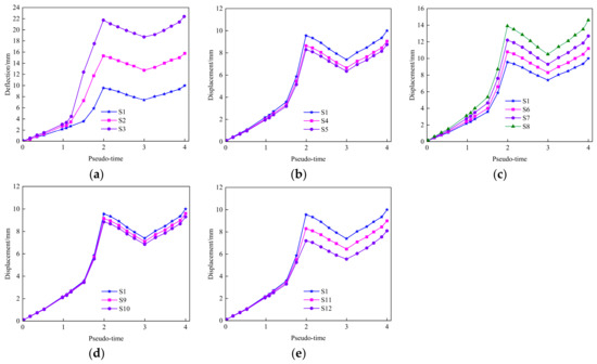
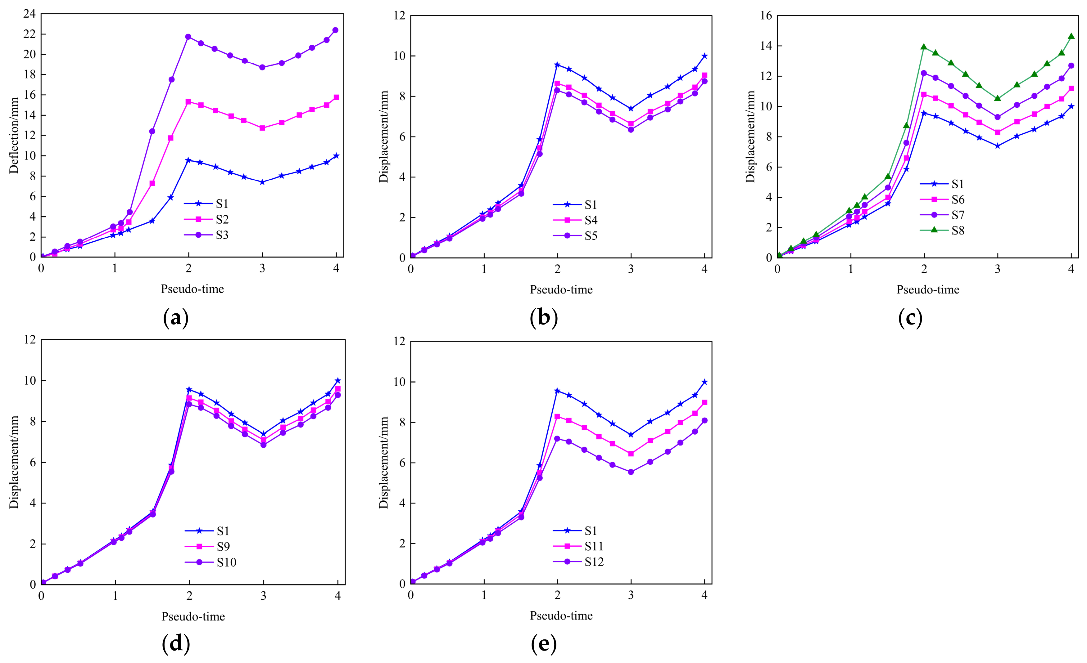
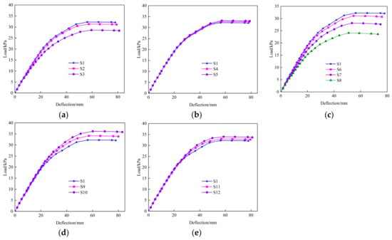
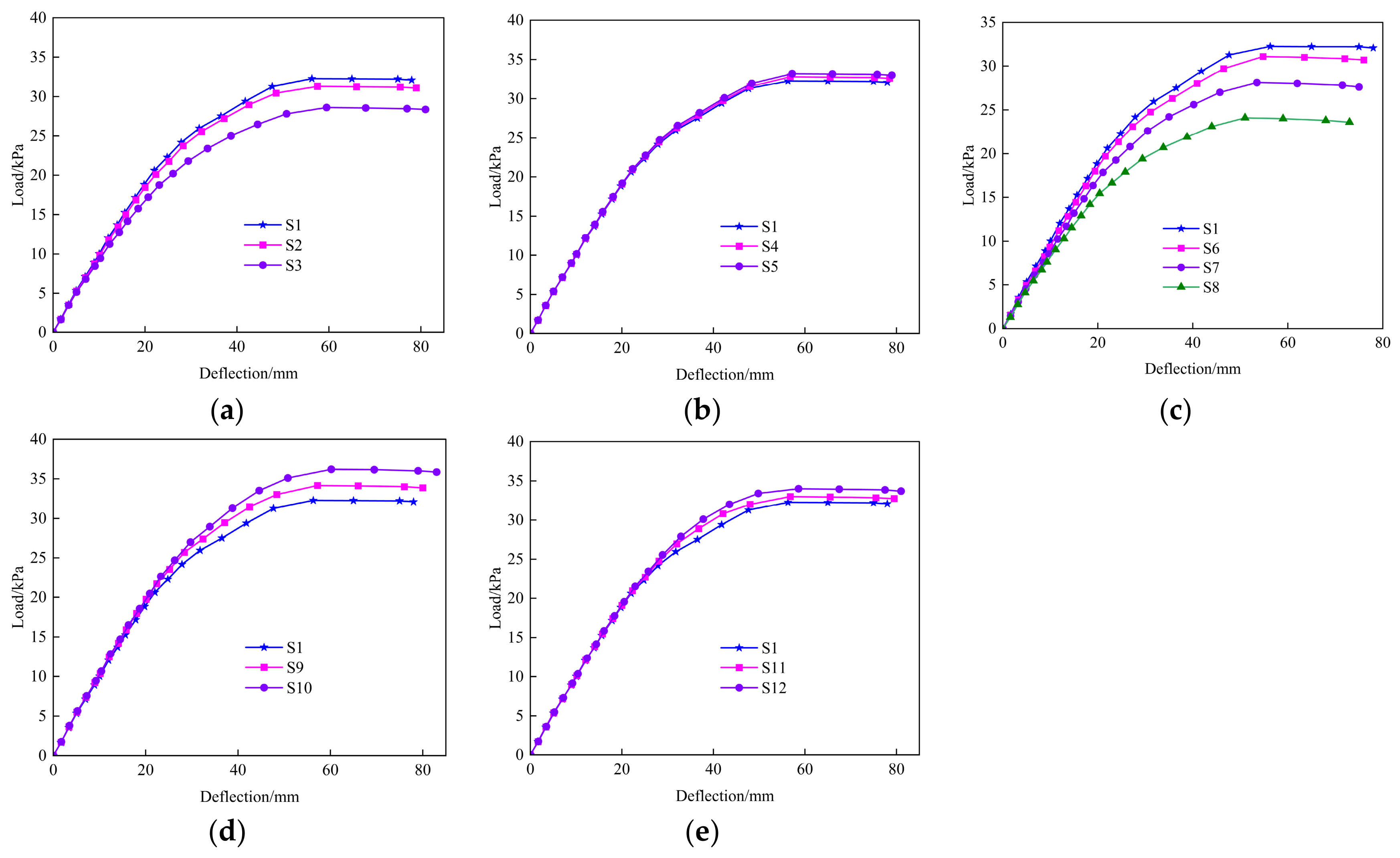
Finite element analyses were conducted on 12 specimens. During the construction stage, the precast base plates were investigated, and the relationship between pseudo-time and mid-span deflection under sequential construction load is presented in Figure 13. During the service stage, the composite slabs were analyzed. During the service stage analysis, monotonic loading was applied until the ultimate state was reached. The peak load was identified as the maximum load obtained from the load–deflection response, representing the ultimate load-carrying capacity of the composite slab. Figure 14 presents the corresponding load–mid-span deflection curves. The service stage responses were obtained based on the completed composite slab state after the construction-stage simulation. The curves represent the incremental deflection induced by service-stage loading.
Figure 13.
The pseudo-time versus deflection curves under different parameters during the construction stage: (a) rib height; (b) rib width; (c) precast base plate thickness; (d) truss reinforcement diameter; (e) truss reinforcement height.
Figure 14.
The mid-span deflection versus load curves under different parameters during the service stage: (a) rib height; (b) rib width; (c) precast base plate thickness; (d) truss reinforcement diameter; (e) truss reinforcement height.
3.3.2. Rib Height
Figure 13a shows that increasing the concrete rib height significantly reduces the deflection of the precast base plate during construction. At Step 2, the maximum deflections of S3, S2, and S1 are 22.6, 15.6, and 9.6 mm, respectively, with S1 showing a 57.5% reduction compared with S3. At Step 4, the corresponding deflections are 22.8, 16.3, and 10.1 mm, and the deflection of S1 is reduced by 55.7% relative to S3. The improvement is mainly attributed to the increased effective section depth and moment of inertia, which enhance the flexural stiffness of the precast base plate. Therefore, increasing the concrete rib height can effectively improve the flexural performance of TRC-SR precast base plates during the construction stage.
Figure 14a shows that the effect of concrete rib height on the overall load–deflection response of the composite slab is relatively limited. The three models exhibit similar stiffness in the initial elastic stage and only moderate differences appear after cracking. The peak loads of S1, S2, and S3 are 32.3, 31.4, and 28.2 kPa, respectively, with S1 showing a 14.5% increase compared with S3. Therefore, increasing the rib height can improve the cracking resistance and post-cracking load-carrying capacity to some extent, but the overall influence on the flexural performance of the composite slab during the service stage is not significant.
3.3.3. Rib Width
Figure 13b shows that increasing the concrete rib width slightly reduces the deflection of the precast base plate during construction, although the overall effect is limited. At Step 2, the maximum deflections of S1, S4, and S5 are 9.6, 8.7, and 8.4 mm, respectively, corresponding to a maximum reduction of 12.5%. At Step 4, the final deflections decrease from 10.1 mm for S1 to 8.8 mm for S5. Therefore, increasing the rib width can moderately improve the flexural stiffness and deformation control of the precast base plate, but its influence is less pronounced than that of rib height.
Figure 14b shows that the load–deflection curves of the three models remain close throughout the loading process, suggesting that the composite slab is relatively insensitive to changes in rib width. Increasing the rib width from 200 mm to 400 mm raises the peak load only from 32.3 kPa to 33.2 kPa, an increase of 2.8%. A slight enhancement is observed mainly in the post-cracking stage, indicating that the wider rib contributes more to improving local stress distribution and crack resistance than to increasing the overall stiffness and bearing capacity of the composite slab.
3.3.4. Precast Base Plate Thickness
Figure 13c shows that reducing the base plate thickness increases the deflection of the precast base plate during construction. At Step 2, decreasing the thickness from 60 mm to 45 mm increases the maximum deflection by 45.8%, while the corresponding increase at Step 4 is 48.7%. This is mainly due to the reduction in sectional moment of inertia and flexural stiffness. Therefore, the base plate thickness has a noticeable influence on construction-stage deformation, although the effect is still less pronounced than that of the rib height.
Figure 14c indicates that the base plate thickness has the pronounced effect on the load–deflection response of the composite slab. As the thickness decreases from 60 mm to 45 mm, the peak load drops from 32.3 kPa to 24.6 kPa, corresponding to a reduction of 23.8%. Thinner base plates also enter the nonlinear stage earlier, reflecting earlier cracking and faster stiffness degradation. Therefore, compared with rib height and rib width, the base plate thickness plays a more important role in governing the service-stage stiffness and bearing capacity of the TRC-SR composite slab.
3.3.5. Truss Reinforcement Diameter
Figure 13d shows that increasing the truss reinforcement diameter produces only a slight reduction in the deflection of the precast base plate during construction. At Step 2, the maximum deflection decreases from 9.6 mm for S1 to 8.8 mm for S10, corresponding to a reduction of 8.3%. Therefore, the truss reinforcement diameter has the relatively limited influence on construction stage deformation, mainly contributing to local load-bearing and crack control performance.
Figure 14d shows that increasing the truss reinforcement diameter mainly improves the post-cracking behavior of the composite slab, while the effect on the initial stiffness is limited. The peak load increases from 32.3 kPa for S1 to 34.1 and 36.5 kPa for S9 and S10, corresponding to increases of 5.6% and 13.0%, respectively. Thus, the larger truss reinforcement diameter can enhance the post-cracking stiffness and bearing capacity, but the influence on the overall load–deflection response remains less significant than that of the base plate thickness.
3.3.6. Truss Reinforcement Height
Figure 13e shows that increasing the truss reinforcement height reduces the deflection of the precast base plate during construction. At Step 2, the maximum deflection decreases from 9.6 mm for S1 to 7.6 mm for S12, corresponding to a reduction of 20.8%. The similar reduction is observed during unloading and at Step 4. Therefore, increasing the truss reinforcement height can moderately improve construction-stage stiffness and deformation resistance, although the effect is less pronounced than that of rib height and base plate thickness.
Figure 14e shows that increasing the truss reinforcement height slightly improves the load–deflection response of the composite slab, mainly after cracking. The peak load increases from 32.3 kPa for S1 to 34.4 kPa for S12, corresponding to an increase of 6.5%. This improvement is attributed to the increased internal lever arm of the reinforcement system. Overall, the truss reinforcement height has only a secondary influence on the service-stage bearing performance compared with the base plate thickness and truss reinforcement diameter.
4. Calculation for Short-Term Flexural Stiffness
4.1. Basic Assumptions
Previous research indicates that rectangular ribs can effectively improve the flexural performance of precast base plates during the construction stage by increasing the effective cross-sectional height and moment of inertia. However, while the numerical simulations can accurately capture nonlinear behavior and crack evolution, the computational complexity limits the direct application in engineering design. Therefore, based on the equivalent section theory, we propose a simplified approach to calculating short-term flexural stiffness in the construction phase, which accounts for the contribution of rectangular rib to the sectional properties of TRC-SR. During the service stage, the cast-in-place concrete hasdeveloped composite action with the precast base plate. The slab behaves as an integral composite member and is similar to that of conventional composite flexural members. Therefore, the calculation method specified in the Code for Design of Composite Structures (JGJ 138-2016) [49] is retained for service-stage stiffness evaluation in this study. As indicated by Figure 14, variations in rib height and rib width cause relatively limited changes in the initial service stage stiffness within the investigated parameter range, although their effects become more evident after cracking. Therefore, this work focuses on determining the short-term flexural stiffness for the precast TRC-SR base plate during the construction stage.
To derive the expression for the short-term flexural stiffness during the construction stage, the following basic assumptions are proposed:
- (1)
- The flexural deformation of the precast base plate satisfies the plane section assumption, and the cross-section remains plane after deformation;
- (2)
- The rectangular rib and the precast base plate work integrally, and the interfacial slip is not considered;
- (3)
- No relative slip occurs between the reinforcement and the concrete;
- (4)
- Since web reinforcement only connects the chords and barely affects flexural stiffness, it is neglected.
4.2. Calculation Formula for the Short-Term Stiffness
In this study, the average stiffness method [49] was adopted. On the basis of the conventional transformed section theory, the effects of the rectangular rib and the spatial arrangement of the truss reinforcement on the sectional stiffness were considered. By establishing transformed section models for both the uncracked and cracked stages of the concrete and incorporating sectional equilibrium analysis, an approach to determining the short-term flexural stiffness of the TRC-SR during construction was proposed. Since the cast-in-place concrete had not yet attained its design strength, the precast base plate was required to independently resist the construction loads and the self-weight of the cast-in-place concrete. Therefore, the transformed section for the uncracked stage was first established to determine the initial sectional stiffness. Subsequently, the effect of the concrete in the tension zone ceasing to carry stress after cracking was considered, and a calculation model for the cracked stage was developed. Finally, the average stiffness method was employed to determine the short-term flexural stiffness of the precast base plate during the construction stage. The calculation diagram is shown in Figure 15.
Figure 15.
The calculation diagram of the precast base plate: (a) before cracking; (b) after cracking.
During the initial loading stage of the construction stage, the concrete in the precast base plate is assumed to be in an uncracked elastic state, and the entire cross-section participates in resisting loads. The modulus ratio αe between the reinforcement and the concrete is defined as follows:
where Es and Ec are the elastic modulus of reinforcement and concrete, respectively.
Considering the transformed reinforcement, the cross-sectional area A0 before cracking can be expressed as
where is the area of the upper chord reinforcement; As is the sum of the area of the longitudinal reinforcement and the lower chord reinforcement.
The distance y0 from the centroid of the transformed section to the bottom surface of the precast base plate can be expressed as follows:
where is the distance from the centroid of the upper chord reinforcement to the bottom of the section; ys is the distance from the centroid of the the lower chord to the bottom of the section.
According to the parallel axis theorem, the moment of inertia Iu of the transformed section in the uncracked stage of the concrete is calculated using the expression given in Equation (12).
After cracking, the concrete in the tension zone is assumed to be ineffective, and the sectional stiffness is provided jointly by the compression concrete and the reinforcement. The position of the neutral axis can be determined based on the equilibrium between the compressive and tensile internal forces by the following equation:
where is the stress of the upper chord reinforcement; x is the distance from the neutral axis of the cracked section to the top surface of the base plate; σc is the maximum compressive stress of the concrete in the compression zone; σr is the maximum compressive stress of the concrete in the rectangular rib; σs is the stress of the lower chord reinforcement.
The position of the neutral axis x in the cracked stage is determined based on the strain compatibility condition and the sectional internal force equilibrium equation. The moment of inertia Ic of the cracked transformed section is then calculated using the parallel axis theorem, as expressed by the following equation:
According to the average stiffness method, the short-term flexural stiffness Bs of TRC-SR during the construction stage accounting for the variation in sectional stiffness before and after concrete cracking can be expressed as follows:
4.3. Verification of the Calculation Formula
Substituting Equation (15), the mid-span deflection δ of the precast base plate under short-term loading is given by
where η is the deflection coefficient associated with the uniformly distributed loading condition and can be taken as 5/384 for the simply supported condition adopted in this study corresponding to the distributed self-weight and construction loads; q is the equivalent uniformly distributed load acting along the span of the precast base plate.
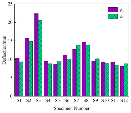
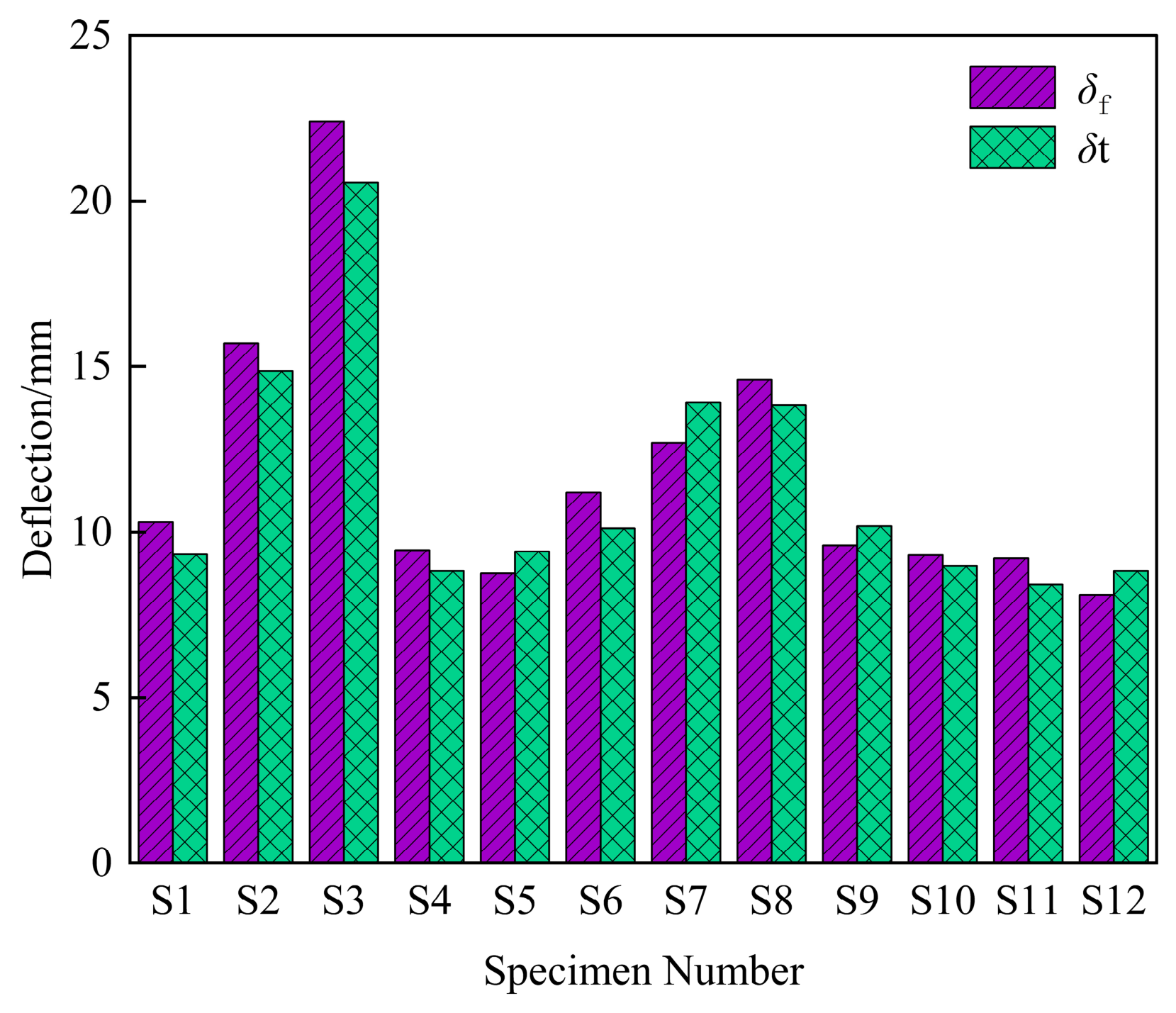
Using Equation (16), the theoretical deflection values δt of the aforementioned 12 specimens were determined. Meanwhile, Finite element analysis was conducted to derive the maximum mid-span deflection δf for the corresponding specimens. The accuracy of the short-term flexural stiffness formula was validated by comparing the theoretical and numerical results. The comparison results are presented in Figure 16.
Figure 16.
Comparison between the theoretical and numerical flexural deformations.
To evaluate the consistency between the theoretical values and the numerical simulations, the ratio of the two was further calculated as v = δf/δt. The results indicate that for the 12 specimens, the average value of v is 1.027, with a standard deviation of 0.078 and a coefficient of variation of 7.57%. The ratio values are generally close to 1 with low dispersion, indicating good agreement between the theoretical deflection values and the finite element simulation results. The individual values of v range from 0.912 to 1.108 and are distributed on both sides of the ideal value of 1.0, indicating no clear systematic bias toward either overprediction or underprediction of deflection by the simplified method. These findings indicate that the proposed short-term flexural stiffness calculation formula can reasonably estimate the construction stage flexural response of the TRC-SR precast base plate within the investigated parameter range.
5. Conclusions
This study investigated the flexural behavior of TRC-SRs, with particular emphasis on the differences between the construction and service stages. A three-dimensional nonlinear finite element model was first established and validated against available experimental results. Based on the verified model, the construction-stage flexural performance of conventional TRC and TRC-SR precast base plates was compared, followed by a parametric study considering the concrete rib height and width, precast base plate thickness, truss reinforcement diameter and truss reinforcement height. Furthermore, a simplified calculation method for the short-term flexural stiffness of TRC-SR precast base plates during construction was developed based on the transformed section and average stiffness approaches. The main conclusions are as follows:
- (1)
- The established nonlinear finite element model can reasonably reproduce the flexural response of the composite slabs. The deviations between the numerical and experimental results for the yielding and ultimate loads are within 10%, while the relative errors in cracking load are 4.7% and 6.5% for the two validation specimens, respectively, demonstrating satisfactory reliability of the numerical model. Although two experimental specimens were used for validation, GHJ-1 and DLB-2 represent the two fundamental structural configurations investigated in this study, namely the conventional TRC and the proposed TRC-SR. The validated model therefore provides a reasonable basis for the comparative analysis and parametric investigations.
- (2)
- Introducing a rectangular concrete rib significantly improves the construction-stage performance of the precast base plate. Under the construction live load, the maximum mid-span deflection of the TRC-SR base plate is 9.6 mm, compared with 26.7 mm for the conventional TRC, corresponding to a reduction of 64.0%. Meanwhile, the maximum principal plastic strain decreases from approximately 2.9 × 10⁻³ to 2.3 × 10⁻³, and the high-strain region becomes more localized. The results indicate that the rectangular rib effectively enhances sectional stiffness and suppresses deformation and tensile damage during construction.
- (3)
- The geometric parameters governing the construction-stage flexural performance of TRC-SRs show different levels of influence. Increasing the rib height from 30 mm to 50 mm reduces the maximum deflection under construction live load by 57.5%, whereas increasing the rib width from 200 mm to 400 mm produces only a 12.5% reduction. Reducing the precast base plate thickness from 60 mm to 45 mm increases the maximum deflection by 45.8%. Therefore, the rib height and precast base plate thickness are the dominant parameters controlling construction-stage deformation, while the effect of rib width is comparatively limited.
- (4)
- During the service stage, the precast base plate thickness has the most pronounced effect on the overall flexural performance of TRC-SRs. Reducing the thickness from 60 mm to 45 mm decreases the peak load from 32.3 kPa to 24.6 kPa, corresponding to a reduction of 23.8%. In comparison, increasing the rib width from 200 mm to 400 mm increases the peak load by only 2.8%, while increasing the rib height from 30 mm to 50 mm results in an increase of approximately 14.5%. The truss reinforcement diameter and height mainly improve the post-cracking response, with the effects on the initial stiffness being relatively limited. It should be noted that the parametric study was conducted using a one-factor-at-a-time strategy to isolate the influence of individual parameters. Therefore, potential interaction effects among multiple parameters were not considered and warrant further investigation in future studies.
- (5)
- A simplified calculation method for the short-term flexural stiffness of the TRC-SR precast base plate during construction was proposed by considering the contribution of the rectangular rib and the change in sectional stiffness before and after cracking. For the 12 parametric models, the mean ratio between the finite element and theoretical deflections is 1.027, with a standard deviation of 0.078 and a coefficient of variation of 7.57%. The good agreement confirms that the proposed method can provide a reasonable prediction of the short-term flexural stiffness and deflection of TRC-SR precast base plates during the construction stage, within the investigated parameter range. The proposed simplified stiffness equation has currently been verified mainly against finite element results, and further validation using independent experimental data is still required before the broader engineering applicability can be established.
Author Contributions
Conceptualization, Y.L.; methodology, Y.L., Y.W. and Z.H. (Zhongde He); software, Y.L. and Z.H. (Ze Huang); validation, Y.W., Y.H. and L.W.; formal analysis, Y.W. and Z.H. (Ze Huang); investigation, L.W.; resources, Z.H. (Zhongde He) and Y.H.; data curation, Y.L. and Y.W.; writing—original draft preparation, Y.L., Y.W. and Z.H. (Zhongde He); writing—review and editing, Y.W. and Z.H. (Zhongde He); visualization, Y.L. and L.W.; supervision, Z.H. (Ze Huang); project administration, Z.H. (Ze Huang) and Y.H. All authors have read and agreed to the published version of the manuscript.
Funding
This research was funded by the Guangdong Provincial Department of Housing and Urban Rural Development Science and Technology Innovation Plan Project (Grant No. 2024-K9-592990).
Data Availability Statement
The authors confirm that the data supporting the findings of this study are available within the article.
Conflicts of Interest
Authors Yun Lin, Yadong Wang and Zhongde He were employed by the company China Railway Shanghai Engineering Bureau Group South China Municipal Construction Co., Ltd. Authors Ze Huang, Yibin Huang and Li Wang were employed by the company Architectural Design & Research Institute of SCUT Co., Ltd. The authors declare that the research was conducted in the absence of any commercial or financial relationships that could be construed as a potential conflict of interest.
References
- Wu, H.; Qiao, G.; Qiao, Y.; Zhong, Z.; Zhou, Z.; Ye, T. Experimental and theoretical research on flexural performance of truss reinforced concrete two-way composite slab with prefabricated baseplate. Structures 2023, 58, 105470. [Google Scholar] [CrossRef] [Scilit]
- Newell, S.; Goggins, J. Experimental Study of Hybrid Precast Concrete Lattice Girder Floor at Construction Stage. Structures 2019, 20, 866–885. [Google Scholar] [CrossRef] [Scilit]
- Xu, A.; Zhu, Y.; Wang, Z.; Zhao, Y. Carbon emission calculation of prefabricated concrete composite slabs during the production and construction stages. J. Build. Eng. 2023, 80, 107936. [Google Scholar] [CrossRef] [Scilit]
- Yee, A.A.; Eng, P.H.D. Social and environmental benefits of precast concrete technology. PCI J. 2001, 46, 14–19. [Google Scholar] [CrossRef] [Scilit]
- Yee, A.A.; Eng, P.H.D. Structural and economic benefits of precast/prestressed concrete construction. PCI J. 2001, 46, 34–43. [Google Scholar] [CrossRef] [Scilit]
- Luo, B.; Tang, Z.H.; Zhao, F.N.; Song, Y.C.; Cao, G. Experimental investigation of the bending behavior of ribbed composite slabs with UHPC liner. Case Stud. Constr. Mater. 2025, 23, e05260. [Google Scholar] [CrossRef] [Scilit]
- Scott, N.L. Performance of precast prestressed hollow core slab with composite concrete topping. PCI J. 1973, 18, 64–77. [Google Scholar] [CrossRef] [Scilit]
- Espeche, A.D.; León, J. Estimation of bond strength envelopes for old-to-new concrete interfaces based on a cylinder splitting test. Constr. Build. Mater. 2011, 25, 1222–1235. [Google Scholar] [CrossRef] [Scilit]
- Hong, L.; Gu, X.; Lin, F. Influence of aggregate surface roughness on mechanical properties of interface and concrete. Constr. Build. Mater. 2014, 65, 338–349. [Google Scholar] [CrossRef] [Scilit]
- Lin, Y.; Wang, H.; Sun, M.; Hu, Y.; Yao, D.; Yan, J. Peak load prediction and interface behavior analysis of steel-ECC composite slabs: Experiments, simulations and theoretical models. Eng. Struct. 2026, 348, 121788. [Google Scholar] [CrossRef] [Scilit]
- Lakshmikandhan, K.N.; Sivakumar, P.; Ravichandran, R.; Jayachandran, S.A. Investigations on efficiently interfaced steel concrete composite deck slabs. J. Struct. Eng. 2013, 2013, 628759. [Google Scholar] [CrossRef] [Scilit]
- Ibrahim, I.S.; Elliott, K.S.; Abdullah, R.; Kueh, A.B.H.; Sarbini, N.N. Experimental study on the shear behaviour of precast concrete hollow core slabs with concrete topping. Eng. Struct. 2016, 125, 80–90. [Google Scholar] [CrossRef] [Scilit]
- Mohamed, M.S.; Thamboo, J.A.; Jeyakaran, T. Experimental and numerical assessment of the flexural behaviour of semi-precast-reinforced concrete slabs. Adv. Struct. Eng. 2020, 23, 1865–1879. [Google Scholar] [CrossRef] [Scilit]
- Gholamhoseini, A.; Gilbert, R.I.; Bradford, M.A.; Chang, Z.T. Longitudinal shear stress and bond-slip relationships in composite concrete slabs. Eng. Struct. 2014, 69, 37–48. [Google Scholar] [CrossRef] [Scilit]
- Chen, S.; Shi, X. Shear bond mechanism of composite slabs-A universal FE approach. J. Constr. Steel Res. 2011, 67, 1475–1484. [Google Scholar] [CrossRef] [Scilit]
- Baran, E. Effects of cast-in-place concrete topping on flexural response of precast concrete hollow-core slabs. Eng. Struct. 2015, 98, 109–117. [Google Scholar] [CrossRef] [Scilit]
- Lee, C.H.; Mansouri, I.; Kim, E.; Hwang, K.S.; Woo, W.T. Flexural strength of one-way composite steel deck slabs voided by circular paper tubes. J. Struct. Eng. 2019, 145, 04018246. [Google Scholar] [CrossRef] [Scilit]
- Al-Fakher, U.; Manalo, A.; Ferdous, W.; Aravinthan, T.; Zhuge, Y.; Bai, Y.; Edoo, A. Bending behaviour of precast concrete slab with externally flanged hollow FRP tubes. Eng. Struct. 2021, 241, 112433. [Google Scholar] [CrossRef] [Scilit]
- Yardim, Y.; Waleed, A.M.T.; Jaafar, M.S.; Laseima, S. AAC-concrete light weight precast composite floor slab. Constr. Build. Mater. 2013, 40, 405–410. [Google Scholar] [CrossRef] [Scilit]
- Mansour, F.R.; Bakar, S.A.; Ibrahim, I.S.; Marsono, A.K.; Marabi, B. Flexural performance of a precast concrete slab with steel fiber concrete topping. Constr. Build. Mater. 2015, 75, 112–120. [Google Scholar] [CrossRef] [Scilit]
- Joseph, J.D.R.; Prabakar, J.; Alagusundaramoorthy, P. Precast concrete sandwich one-way slabs under flexural loading. Eng. Struct. 2017, 138, 447–457. [Google Scholar] [CrossRef] [Scilit]
- Sohel, K.M.; Liew, J.R.; Fares, A.I. Shear bond behavior of composite slabs with ultra-lightweight cementitious composite. J. Build. Eng. 2021, 44, 103284. [Google Scholar] [CrossRef] [Scilit]
- Kefyalew, F.; Imjai, T.; Garcia, R.; Kim, B. Structural and service performance of composite slabs with high recycled aggregate concrete contents. Eng. Sci. 2023, 27, 1021. [Google Scholar] [CrossRef] [Scilit]
- Simoncelli, M.; Pisani, M.A.; Bernuzzi, C.; Zucca, M.; Alibeigibeni, A.; Stochino, F. Finite element simulation of composite slabs with recycled concrete aggregates: Collapse mechanisms and interface behaviour. Mater. Struct. 2026, 59, 17. [Google Scholar] [CrossRef] [Scilit]
- Al-Rubaye, M.; Manalo, A.; Alajarmeh, O.; Ferdous, W.; Lokuge, W.; Benmokrane, B.; Edoo, A. Flexural behaviour of concrete slabs reinforced with GFRP bars and hollow composite reinforcing systems. Compos. Struct. 2020, 236, 111836. [Google Scholar] [CrossRef] [Scilit]
- Zhang, J.L.; Liu, B.D.; Liu, R. Behavior of sinusoidal-corrugated-steel-plate-concrete composite slabs: Experimental investigation and theoretical model development. J. Constr. Steel Res. 2021, 187, 106958. [Google Scholar] [CrossRef] [Scilit]
- Liu, R.; Yang, Y. Research on fatigue performance of steel-plate-concrete composite slab. Thin-Walled Struct. 2021, 160, 107339. [Google Scholar] [CrossRef] [Scilit]
- Ferrer, M.; Marimon, F.; Casafont, M. An experimental investigation of a new perfect bond technology for composite slabs. Constr. Build. Mater. 2018, 166, 618–633. [Google Scholar] [CrossRef] [Scilit]
- Zhang, A.; Chen, Z.; Liu, J. Flexural performance of innovative thin-walled steel-timber composite floor slabs. Eng. Struct. 2024, 318, 118676. [Google Scholar] [CrossRef] [Scilit]
- Jakovljević, I.; Spremić, M.; Marković, Z. Effect of rib-to-beam angle on the shear resistance of headed studs in composite slab. Eng. Struct. 2024, 303, 117574. [Google Scholar] [CrossRef] [Scilit]
- Yang, Y.; Wu, B.; Xu, L.Y.; Yao, Y.P.; Zhang, D.; Zhao, C. Experimental study on the buckling behavior of double steel plate concrete composite slabs with stiffening ribs and tie plates. Eng. Struct. 2022, 255, 113895. [Google Scholar] [CrossRef] [Scilit]
- Soltanalipour, M.; Ferrer, M.; Marimon, F. Experimental and numerical study of the ductility of open-rib and reentrant composite slabs. Eng. Struct. 2022, 256, 113984. [Google Scholar] [CrossRef] [Scilit]
- Jiang, Y.; Liu, L.; Wang, X.; Liu, R.; Yang, H. Study on bending performance of high-ductility composite slab floor with composite ribs. Materials 2025, 18, 658. [Google Scholar] [CrossRef] [Scilit] [PubMed]
- Chen, Y.; Chen, Y.; Zhang, M.; Ye, X.; Zhang, J. Research on the mechanical properties of lightweight unbraced prefabricated reinforced truss composite base slabs. Struct. Durab. Health Monit. 2026, 20, 21. [Google Scholar] [CrossRef] [Scilit]
- Hoang, V.H.; Do, T.A.; Tran, A.T.; Nguyen, X.H. Flexural capacity of reinforced concrete slabs retrofitted with ultra-high-performance concrete and fiber-reinforced polymer. Innov. Infrastruct. Solut. 2024, 9, 113. [Google Scholar] [CrossRef] [Scilit]
- Chen, S. Load carrying capacity of composite slabs with various end constraints. J. Constr. Steel Res. 2003, 59, 385–403. [Google Scholar] [CrossRef] [Scilit]
- Li, Y.; Shen, H.; Shan, W.; Han, T. Flexural behavior of lightweight bamboo-steel composite slabs. Thin-Walled Struct. 2012, 53, 83–90. [Google Scholar] [CrossRef] [Scilit]
- Guo, S.; Bailey, C.G. Experimental behaviour of composite slabs during the heating and cooling fire stages. Eng. Struct. 2011, 33, 563–571. [Google Scholar] [CrossRef] [Scilit]
- Men, P.; Chen, F.; Qin, F.; Peng, X.; Di, J.; Jiao, H. Behavior of composite beams with UHPC-concrete composite slabs under negative bending moment. J. Constr. Steel Res. 2025, 227, 109415. [Google Scholar] [CrossRef] [Scilit]
- Liu, X.; Ni, D.Y.; Li, J. Experimental Study and Finite Element Analysis of Prefabricated ribbed Steel Truss Laminated Slabs. J. Shenyang Jianzhu Univ. (Nat. Sci.) 2018, 34, 42–52. (In Chinese) [Google Scholar]
- Nie, J.G.; Wang, Y.H. Comparison study of constitutive model of concrete in Abaqus for static analysis of structures. Eng. Mech. 2013, 30, 59–68. (In Chinese) [Google Scholar]
- Lee, J.; Fenves, G.L. Plastic-damage model for cyclic loading of concrete structures. J. Eng. Mech. 1998, 124, 892–900. [Google Scholar] [CrossRef] [Scilit]
- Genikomsou, A.S.; Polak, M.A. Finite element analysis of punching shear of concrete slabs using damaged plasticity model in ABAQUS. Eng. Struct. 2015, 98, 38–48. [Google Scholar] [CrossRef] [Scilit]
- Hany, N.F.; Hantouche, E.G.; Harajli, M.H. Finite element modeling of FRP-confined concrete using modified concrete damaged plasticity. Eng. Struct. 2016, 125, 1–14. [Google Scholar] [CrossRef] [Scilit]
- Voyiadjis, G.Z.; Taqieddin, Z.N.; Kattan, P.I. Anisotropic damage-plasticity model for concrete. Int. J. Plast. 2008, 24, 1946–1965. [Google Scholar] [CrossRef] [Scilit]
- Lemaitre, J. Coupled elasto-plasticity and damage constitutive equations. Comput. Methods Appl. Mech. Eng. 1985, 51, 31–49. [Google Scholar] [CrossRef] [Scilit]
- Zheng, F.; Wu, Z.; Gu, C.; Bao, T.; Hu, J. A plastic damage model for concrete structure cracks with two damage variables. Sci. China Technol. Sci. 2012, 55, 2971–2980. [Google Scholar] [CrossRef] [Scilit]
- CECS 273:2010; Code for Composite Slabs Design and Construction. China Planning Press: Beijing, China, 2010.
- JGJ 138-2016; Code for Design of Composite Structures. China Building Industry Press: Beijing, China, 2016.



Disclaimer/Publisher’s Note: The statements, opinions and data contained in all publications are solely those of the individual author(s) and contributor(s) and not of MDPI and/or the editor(s). MDPI and/or the editor(s) disclaim responsibility for any injury to people or property resulting from any ideas, methods, instructions or products referred to in the content. |
© 2026 by the authors. Licensee MDPI, Basel, Switzerland. This article is an open access article distributed under the terms and conditions of the Creative Commons Attribution (CC BY) license.