


Abstract
In the construction of large-scale caissons, it is difficult to obtain accurate values of the end resistance. There are also inclination, sand boiling, and other issues. In this study, a simplified calculation model for the broken-line end-bearing capacity was proposed on the basis of the passive extrusion failure theory of foundations. Simplified calculation formulas for the bearing capacity under different soil support conditions were established, considering the impacts of excavation or burial depth on the failure slip surface and bearing capacity of the foundation. In addition, the impacts of different shapes of caisson components on the end resistance were analyzed. On the basis of this analysis, a bearing capacity correction coefficient was introduced that considers three-dimensional spatial effects; the calculation results of the end resistance method deviate from the on-site measured earth pressure values by no more than 10%. The dominant influences of the inclining moment and resisting moment on the caisson’s attitude varied progressively as the caisson continued to sink. In the construction of large-scale caissons, end resistance emerged as the primary factor governing the caisson’s orientation. Accordingly, a “stepped progressive” sinking control method was developed and implemented during the caisson sinking operations for Pier No. 5 of the Changzhou-Taixing Yangtze River Bridge. By actively controlling the width of the supporting soil at the end of the caisson and the burial depth, the verticality of the caisson throughout the construction process remained within 1/150. The verticality of the final sinking of the caisson exceeded 1/2000, and the torsional angle of the final sinking of the caisson was only 0.07°. This achieved the active control of the end resistance of the large caisson, the process of sinking, the attitude during the sinking, and the risk of sand boiling.
1. Introduction
Large-scale bridges are developing toward long-span heavy-load bridges integrated with multiple traffic functions. With increasing bridge spans and loads, caissons, as common bridge foundation structures, have increasingly larger planar dimensions and scales. However, complex interaction mechanisms exist between large-scale caissons and soil. The sinking process of large-scale caissons is under passive deviation correction control, leading to frequent occurrences of structural cracking, sand boiling, inclination, and other risks.
Researchers have explored the sinking mechanism and construction control techniques for caissons through theoretical analysis, numerical calculations, and field or laboratory tests. Templeman et al. (2023) employed finite element limit analysis to investigate the influence of cutting edge geometry, interface roughness, embedded depth, and soil internal friction angle on open caisson sinking resistance [1]. Suppakul et al. (2024) proposed a bearing capacity calculation equation based on an artificial neural network algorithm [2]. Keskin et al. (2013) analyzed the influences of different parameters on the bearing capacities of sloped foundations via indoor model tests [3]. Numerical simulations were conducted to investigate the failure modes of sloped foundations [3]. Jiang BN et al. (2019) conducted model tests on the caisson foundation of the Shanghai-Suzhou-Nantong Yangtze River Bridge [4]. The results indicated that seepage forces, cutting-edge reaction forces, lateral earth pressures, sand boiling, and sudden sinking are all closely associated with the movement of sand particles. Lai F. et al. (2021) employed a Multivariate Adaptive Regression Splines (MARS) model to analyze the sensitivity of caisson design parameters, demonstrating the model’s capability to accurately capture complex, multidimensional nonlinear relationships between input and output variables [5]. Zhang J. (2021) identified the presence of excess pore water pressure in the soil surrounding the area beneath the caisson’s cutting edge [6]. Additionally, several researchers have examined the earth pressure at the caisson base and the dynamics of the sinking process, offering valuable insights for guiding caisson construction practices (Guo M. et al. 2021) [7]. Taking the caisson for the Oujiang Beikou Bridge as an example, Yan et al. (2021) demonstrated that the earth pressure at the caisson end can be reduced by layered excavation during caisson construction [8]. Yea et al. (2012) conducted field tests and explored the three-dimensional (3D) distribution pattern of earth pressure during the sinking of a caisson at the Yeongjong Bridge in South Korea [9]. However, owing to complex interactions with soil, caisson structures exhibit significantly nonlinear and plastic mechanical properties during sinking (K. Sobhan, 2012) [10]. In recent years, a series of sensors have typically been installed during caisson construction to capture the sinking status (Royston R. et al. 2022) [11]. Consequently, a large volume of data is generated, making data analysis challenging. Existing data-driven analysis and prediction methods include data-driven automatic identification based on computer vision techniques (Zhou X. et al. 2019 and Hoang N D. 2020), crack detection using convolutional neural networks (Kong X. et al. 2018), and algorithms that are based on hybrid artificial neural networks (Gordan M. et al. 2020) [12,13,14,15]. Based on the current research results, it is difficult to obtain the end resistance of the caisson precisely and quickly. During the caisson construction process, the main focus is on sensing the construction status. When abnormalities occur in the caisson’s posture, end resistance, stress, etc., the construction will be adjusted, which are all passive construction control methods. The construction of caissons still has high uncertainty and risks. There is an urgent need to develop precise calculation methods for end resistance and side resistance during the caisson construction process, as well as quantitative correlation calculation methods for the target posture of the caisson and the resistance it experiences. Further research is needed in these areas to achieve active control methods that can predict and adjust before the caisson undergoes abnormalities.
In this study, the sinking mechanism of a large-scale caisson was explored while considering the influence of caisson construction. Calculation methods for foundation bearing capacity considering construction impacts and 3D effects of the structure were derived through analysis of relevant theoretical methods. Furthermore, an active control method for the construction of large-scale caissons was introduced to prevent caisson inclination and deviation. The purpose was to explore a new pattern for the construction of large-scale caissons.
2. Bearing Capacity Calculation Methods
Foundation bearing capacity is a critical parameter in caisson sinking operations. To ensure the smooth progression of construction, it is essential to obtain an accurate estimation of this parameter. Given the dynamic nature of caisson construction, the bearing capacity is not constant but varies in relation to the width and burial depth of the supporting soil at the caisson base. Therefore, this study proposes precise calculation methods tailored to large-scale caissons, taking into account the structural configuration, excavation conditions, and sinking construction characteristics specific to such foundations.
2.1. Simplified Algorithm for the Bearing Capacity
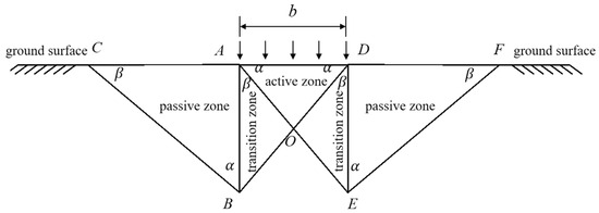
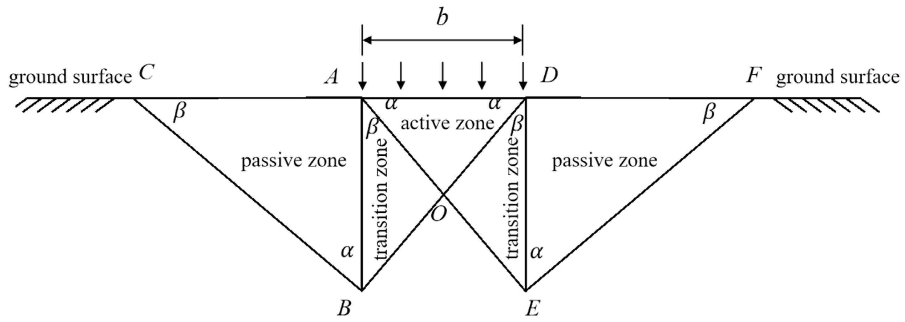
To simplify the calculation of the foundation bearing capacity, the foundation was assumed to undergo bilateral fracture-line slip failure under loading. The failure zone was divided into an active zone, a transition zone, and a passive zone (Figure 1). Given the soil friction angle φ, the following formulas were obtained: α = 45° + φ/2, and β = 45° − φ/2.
Figure 1.
Simplified failure mode of the foundation bearing capacity.
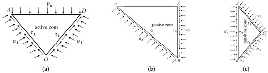
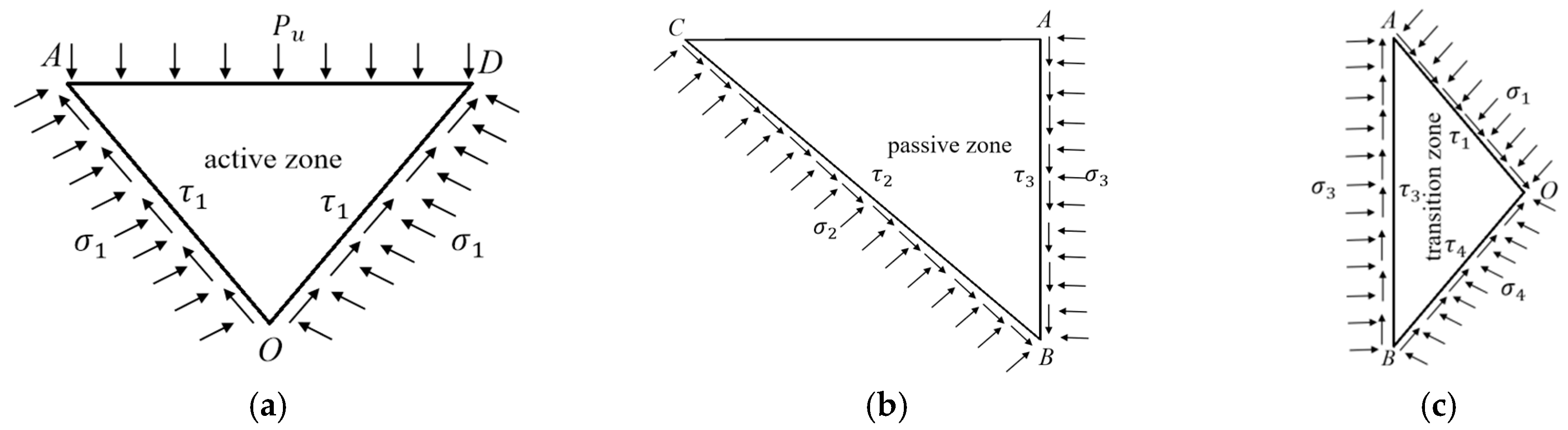
The forces in the active zone, transition zone, and passive zone were analyzed, as shown in Figure 2. When slip failure occurred in the foundation, the following conditions were applied:
Figure 2.
Force analysis of each zone: (a) active zone, (b) passive zone and (c) Transition zone.
According to Figure 1 and Figure 2, there are a total of 9 unknown quantities: , , , , , , , and . The horizontal and vertical forces in the active zone, passive zone, and transition zone are balanced, allowing for the establishment of 6 equilibrium equations. Combined with Formulas (1)–(3), there are a total of 9 equilibrium equations. Through these equilibrium equations, the foundation bearing capacity can be solved as follows:
where is the coefficient for the passive earth pressure:
2.2. Foundation Bearing Capacity Considering Caisson Excavation
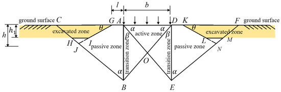
As excavation slopes are created during the excavation of caisson compartments, the excavated zone could weaken the foundation bearing capacity (Figure 3).
Figure 3.
The foundation bearing capacity considering excavation.
The following formula was derived considering the weight of the soil in the excavated zone and its impact on the forces acting on the slip surface, as well as the force equilibrium in each zone:
where is the weakening coefficient for the foundation bearing capacity:
2.3. Foundation Bearing Capacity Considering the Burial Depth of the Foundation
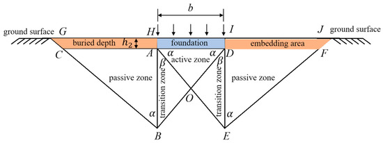
When the foundation bearing capacity was low, the caisson end penetrated to a certain depth into the foundation (Figure 4). The weight of the soil in the buried zone and its acting force on the slip lines further strengthened the foundation bearing capacity.
Figure 4.
The foundation bearing capacity considering the burial depth of the foundation.
Considering the force equilibrium in each zone, the following formula was derived:
where is the enhancing coefficient for the foundation bearing capacity:
2.4. Foundation Bearing Capacity Considering the 3D Effects of the Structure
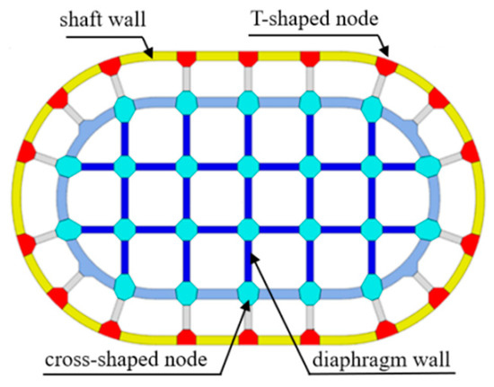
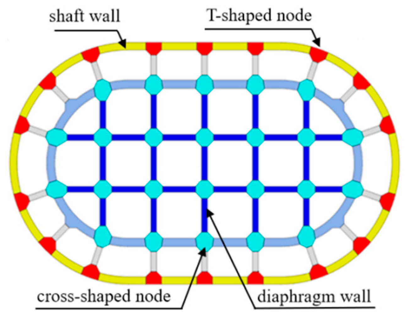
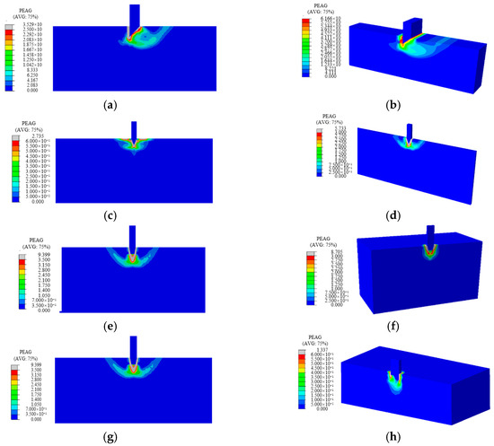
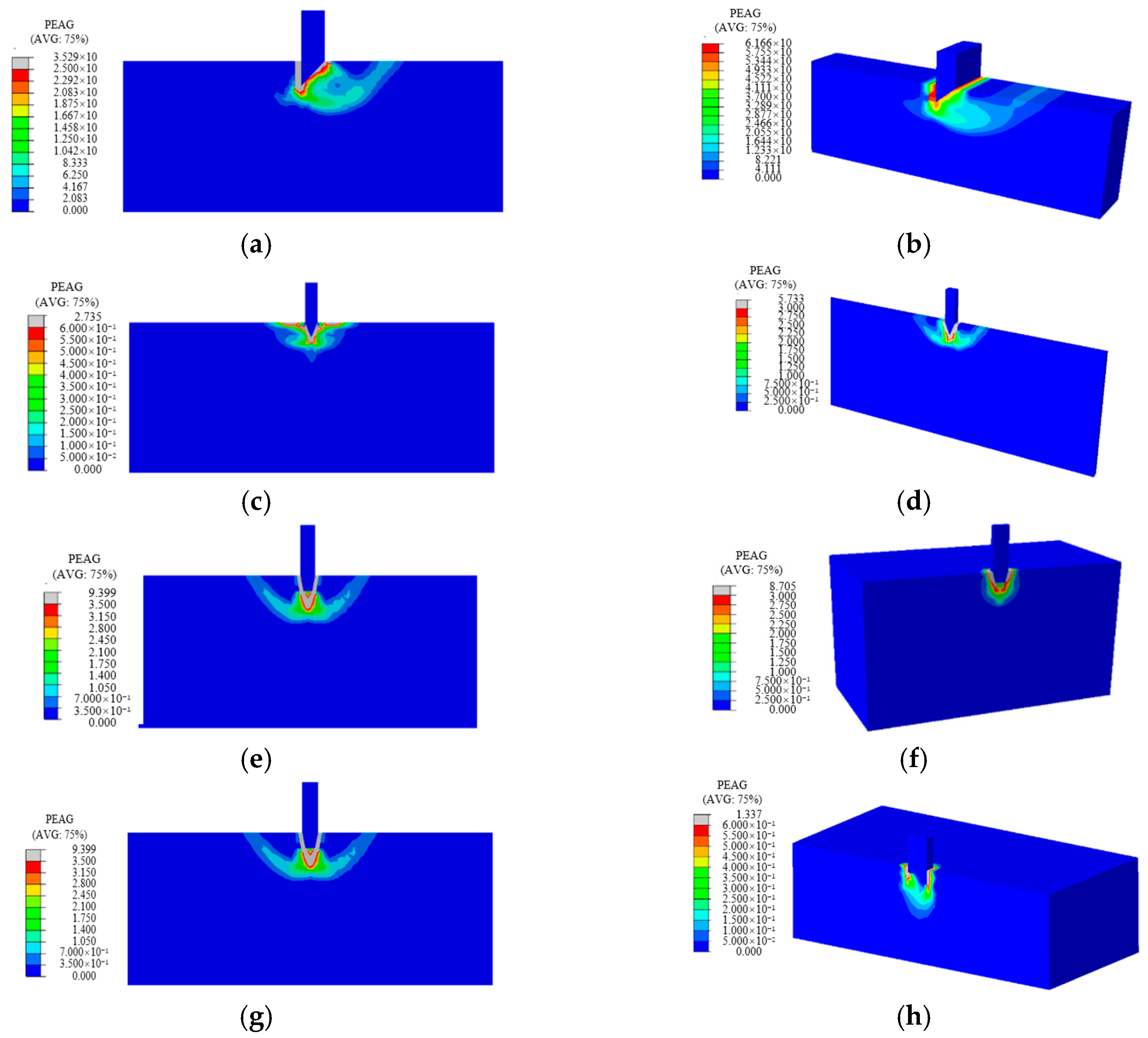
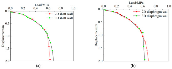
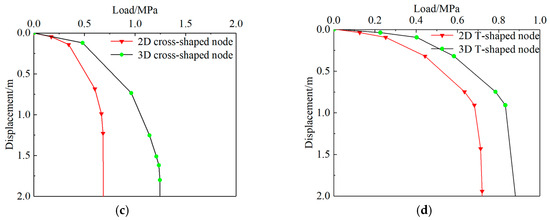
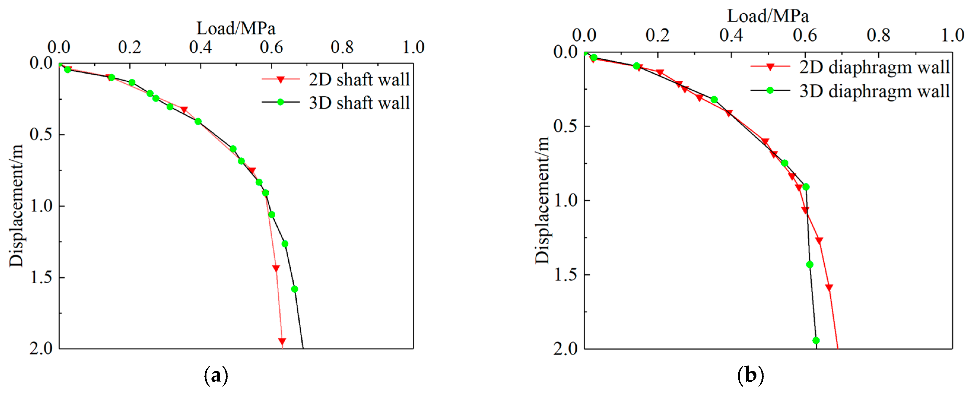
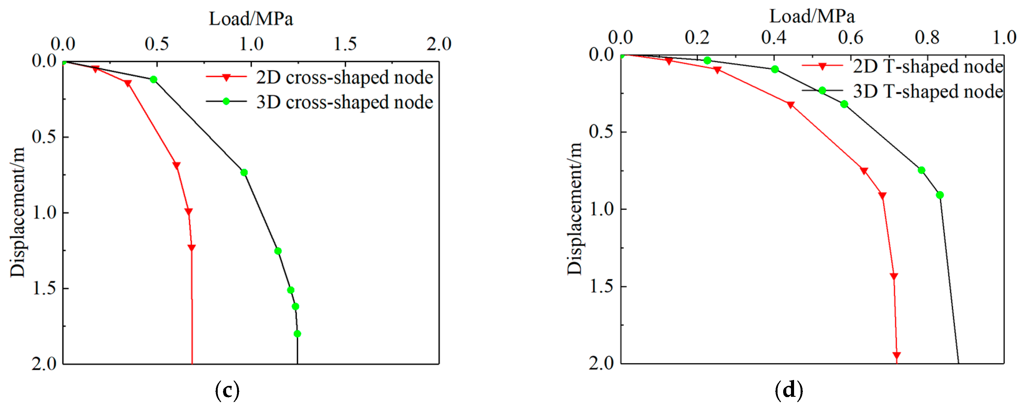
The stability of the supporting soil can be affected by excavation depth and the depth at which the structure is embedded. The caisson structure itself consists of several key elements, including the cutting edges of the shaft wall, diaphragm walls, as well as cross-shaped and T-shaped nodes (Figure 5). Due to the distinct geometric forms and mechanical behaviors of these components, evaluating bearing capacity requires consideration of their 3D structural effects. This section uses the dense silt layer beneath the caisson of Pier No. 5 on the Changzhou-Taixing Yangtze River Bridge as a case study, with soil properties listed in Table 1. The soil layer parameters are derived from the geological investigation report. Using the finite element numerical calculation method, the soil is modeled with the Mohr-Coulomb model, and the caisson structure is calculated using the elastic constitutive model. The unique configurations of the caisson components were analyzed using both two-dimensional (2D) and 3D numerical simulations, as illustrated in Figure 6. The resulting bearing capacity values from these simulations for the different components are shown in Figure 7.
Figure 5.
Components of the caisson.
Table 1.
Parameters of dense silt in the caisson.
Figure 6.
2D and 3D models of different caisson components: (a) 2D model of a shaft wall, (b) 3D model of a shaft wall, (c) 2D model of a diaphragm wall, (d) 3D model of a diaphragm wall, (e) 2D model of a cross-shaped node, (f) 3D model of a cross-shaped node, (g) 2D model of a T-shaped node and (h) 3D model of a T-shaped node.
Figure 7.
Numerical calculation results for different component shapes: (a) shaft walls, (b) diaphragm walls, (c) cross-shaped nodes and (d) T-shaped nodes.
Based on the load–displacement curves obtained through numerical calculation of different component shapes, select the points where the displacement suddenly increases under a certain load condition as the two-dimensional and three-dimensional bearing capacities of component shapes. The ratio of the calculated end resistance of the three-dimensional and two-dimensional cases will be used as the three-dimensional effect correction coefficient for the caisson structure. The values of the 3D effect correction coefficients for different components were as follows: 1.8 for cross-shaped nodes, 1.15 for T-shaped nodes, and 1.0 for the cutting edges of the shaft wall and diaphragm walls. These 3D correction coefficients were then incorporated into the 2D bearing capacity calculation Formulas (4), (6) and (8). By derivation, a refined calculation method for the sinking bearing capacity considering the 3D effects of the cutting-edge structure and the supporting soil yields Formula (10):
3. Interaction Relationship Between Sinking Attitude and Soil
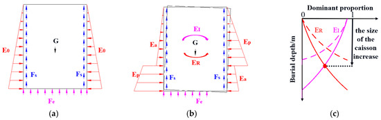
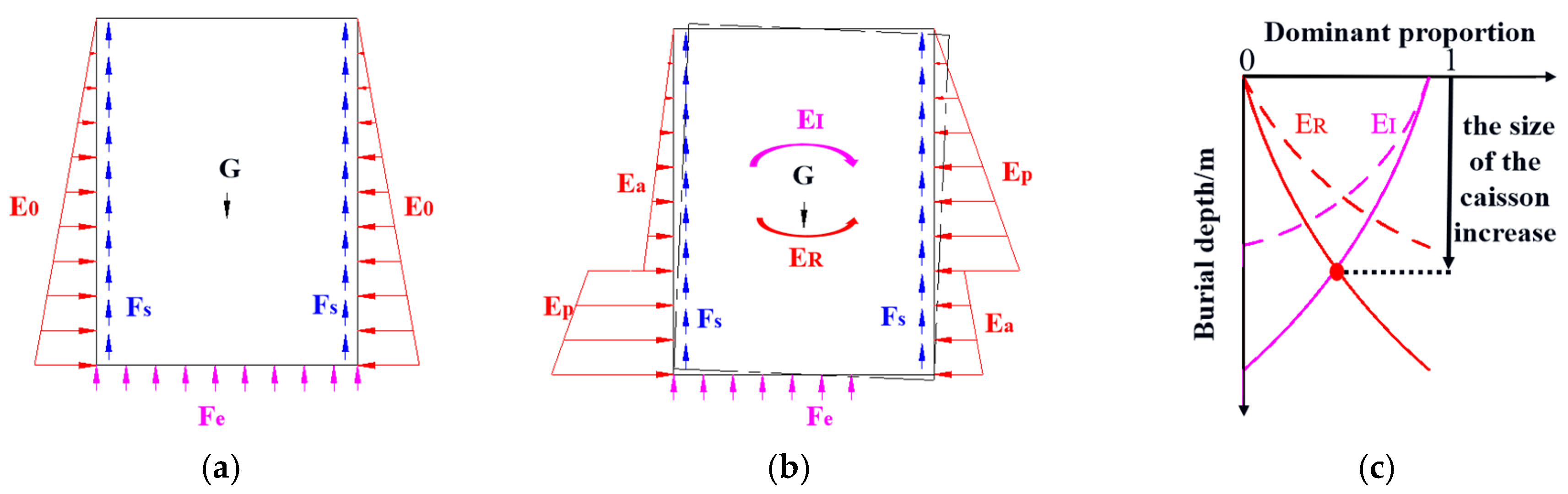
During caisson construction, a structure is subjected primarily to the effects of its weight, buoyancy, end resistance, lateral resistance, and horizontal earth pressure. The weight and buoyancy were accurately calculated on the basis of the volume of the caisson. The end resistance was calculated on the basis of the end support area and foundation bearing capacity. The foundation bearing capacity was calculated using Formula (10) on the basis of the width and burial depth of the soil at the caisson end. The horizontal earth pressure and lateral resistance are related to the caisson attitude. When the caisson maintains a good attitude during sinking, its sides are subjected to earth pressure at rest, as shown in Figure 8a. When the caisson exhibited an unfavorable inclination, the upper two-thirds of its embedded section on the inclined side experienced passive earth pressure, while the lower one-third was subjected to active earth pressure. Conversely, on the opposite side, the upper portion was subjected to active earth pressure and the lower portion to passive earth pressure, as illustrated in Figure 8b. The distribution of horizontal earth pressure was categorized into active pressure, earth pressure at rest, and passive pressure, and was determined using Rankine’s earth pressure theory. The active earth pressure is a function related to the friction angle of the soil, cohesion , active earth pressure coefficient , burial depth , and unit weight of the soil, as expressed in Formula (11):
Figure 8.
Analysis of the forces on the sinking caisson: (a) uniform support, (b) non-uniform support and (c) main control factors for attitude.
The correlation function for the earth pressure at rest is given by Formula (12), where represents the coefficient for the earth pressure at rest:
The correlation function for the passive earth pressure is expressed as Formula (13), where denotes the coefficient for the passive earth pressure:
The frictional force between the soil and the caisson structure was calculated by multiplying the horizontal earth pressure on the structure by the friction coefficient , as expressed in Formula (14):
During the uniform soil extraction and sinking process of the caisson, the support at the end of the caisson presents uniform symmetry. The resistance at the end of the caisson coincides with the center of the caisson, thus no inclination moment will be generated. When the horizontal soil pressure distribution around the caisson is uniform, the caisson will maintain a good posture during the sinking process. When the caisson was under non-uniform excavation or poor attitude, the structure was subjected to asymmetric forces. The end resistance generated an incline moment, whereas the lateral resistance from the surrounding soil and the horizontal earth pressure produced an anti-inclining moment. At the initial sinking stage, the caisson was free from lateral soil constraints, and its attitude fully depended on the uniformity of the end support. At this time, the dominant effect of the end resistance on the caisson attitude was defined as 1. As the burial depth increased, the caisson was under increasing constraints on the surrounding soil, whereas the dominant effect of the end resistance on the caisson attitude weakened. When the inclination moment equaled the resisting moment, the corresponding burial depth represented the depth range where the end resistance dominated the caisson attitude (Figure 8c). Compared with caissons with smaller planar dimensions, caissons with larger planar dimensions exhibit a greater burial depth range where the end resistance dominates the caisson attitude. After the caisson sank to a certain depth, the caisson attitude was well constrained from inclining by the surrounding soil regardless of the distribution of the end resistance. At this stage, the dominant effect of the end resistance on the attitude became zero, whereas that of the surrounding soil constraint on the attitude was 1. For large caissons, the end resistance usually plays a dominant role.
4. Active Control Method for the Singking of Large-Scale Caissons
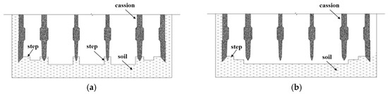
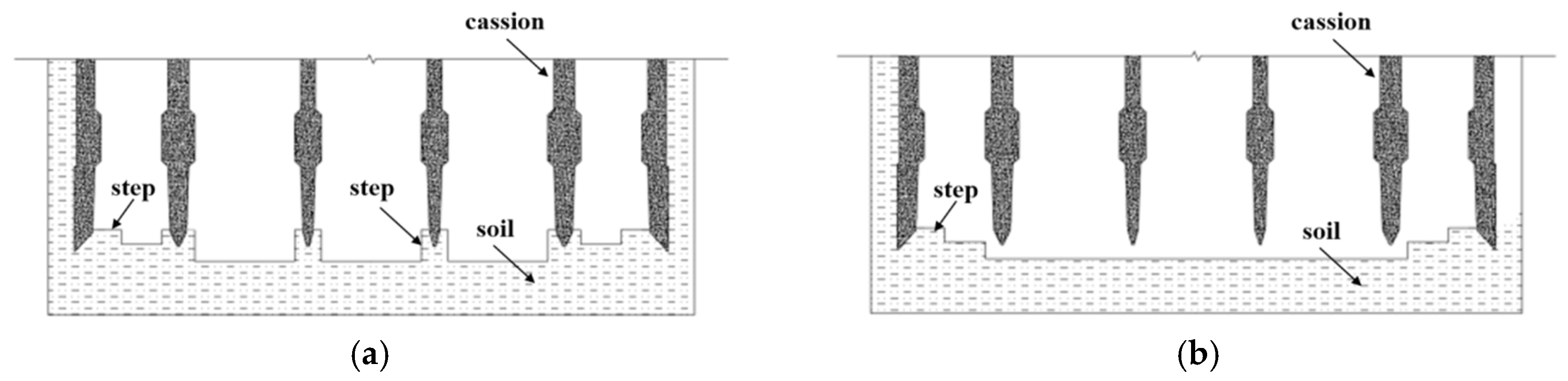
When the conventional “basin-shaped excavation” technique is employed for caisson sinking, the structure becomes highly susceptible to cracking. This vulnerability stems from the caisson’s low initial stiffness and limited confinement by surrounding soil during the early stages of sinking. As a result, it becomes challenging to control the burial depths of the cutting edges in the later stages, heightening the risk of phenomena such as sand boiling and structural inclination. To mitigate these issues, a stepped progressive support conversion strategy was introduced. In particular, a multi-step support system was implemented during the initial sinking phase, as shown in Figure 9a. This approach minimized the suspended span of the caisson, promoting rapid penetration while maintaining structural integrity. As the caisson descended and its stiffness increased, the permissible suspended span was gradually extended. During the subsequent sinking phase, the central step supports were systematically removed, transitioning the structure to a less-stepped support layout, illustrated in Figure 9b. The lateral frictional resistance acting on the caisson was obtained based on Formula (14), and the critical end resistance for sinking of the caisson was calculated. The bearing capacity values under different support conditions were calculated according to Formulas (4), (6), (8) and (10), and the number of sinking steps of the caisson was obtained through calculation. Additionally, the growing burial depth increases the likelihood of sand boiling, necessitating precise control over both the soil support width and the cutting edge burial depth to ensure stable and continuous sinking.
Figure 9.
Stepped progressive support conversion: (a) multi-step support at the initial sinking stage and (b) less-step support at the latter sinking stage.
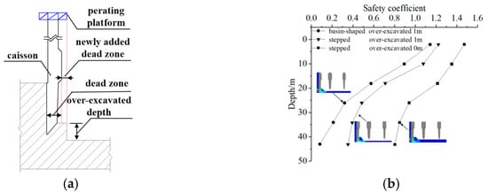
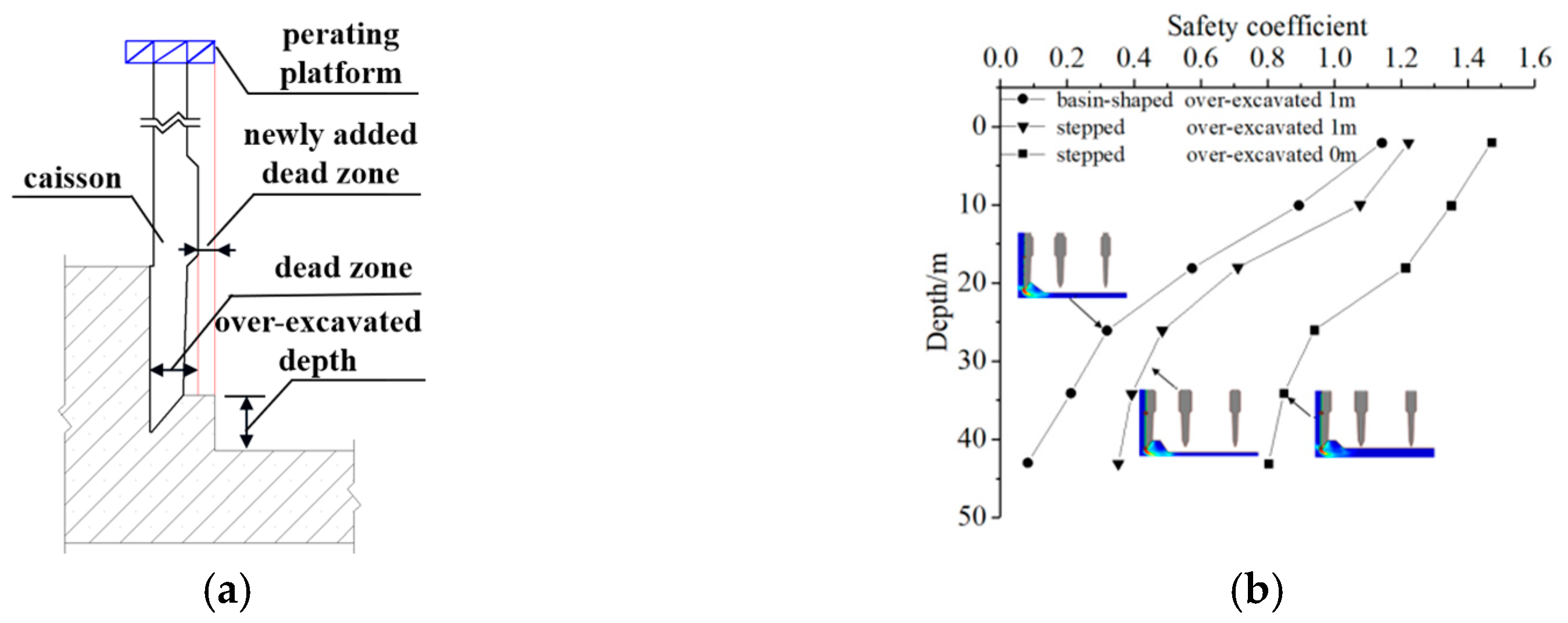
Furthermore, the traditional basin-shaped excavation method was compared with the proposed stepped progressive support conversion method via finite element numerical simulations of surveyed caissons. The results are displayed in Figure 10. When the burial depth of the cutting edge was over-excavated by 1 m, the sand boiling risk of the proposed method was about 30% lower than that of the traditional method.
Figure 10.
Comparative analysis of the risk of sand boiling during caisson sinking: (a) over-excavated depth of the caisson and (b) comparison of sand boiling risks.
5. Engineering Application
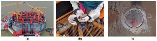
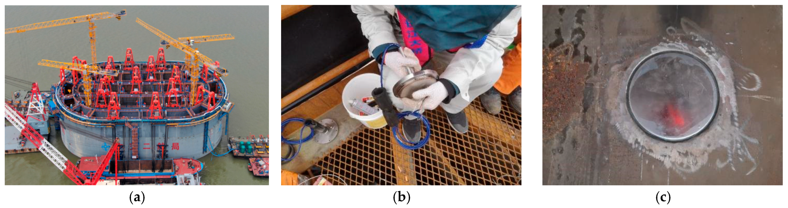
The No. 5 The pier of the Changzhou-Taixing Yangtze River Bridge adopted a caisson foundation (Figure 11a). This caisson, with a size of 95.4 m × 58.2 m × 64 m, is the world’s largest overwater caisson project. The stratum for sinking consists of alternating layers of sand and clay. The soil layer is uneven, with elevation differences of nearly 5 m. It is overlain by a hard plastic silty clay layer. The sand layer contains bedded cemented layers, with thicknesses ranging from 2 to 15 cm and an average compressive strength of 5.59 MPa.
Figure 11.
Caisson for No.5 Pier of the Changzhou-Taixing Yangtze River Bridge: (a) caisson, (b) earth pressure box and (c) Field Installation effect.
Earth pressure at the base of the caisson was monitored, as illustrated in Figure 11b,c. The caisson was embedded in successive strata of dense coarse sand, dense fine sand, and silty clay. The sloped surface’s top edge was located 1 m from the diaphragm wall, with burial depths of 0 m, −0.5 m, and −1.0 m, respectively. Under these conditions, theoretical calculations were conducted to estimate the earth pressure acting on the diaphragm walls and the end bearing resistance, as summarized in Table 2. The calculated end resistance, which accounted for the effects of caisson excavation, showed a deviation of less than 10% from the field-monitored earth pressure values, indicating strong agreement between theoretical predictions and actual measurements.
Table 2.
Comparison between theoretically calculated results and field monitoring data.
The earth pressure values recorded on site were compared across strata comprising dense coarse sand, dense fine sand, and silty clay. The corresponding 3D correction coefficients for cross-shaped and T-shaped nodes are presented in Table 3. The 3D correction coefficient for cross-shaped nodes was found to range between 1.76 and 1.87, aligning closely with the recommended value of 1.80. Likewise, the coefficient for T-shaped nodes ranged from 1.14 to 1.19, showing near equivalence to the recommended value of 1.15.
Table 3.
The 3D Effect correction coefficients for different components of the caisson structure.
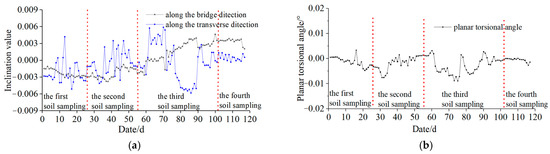
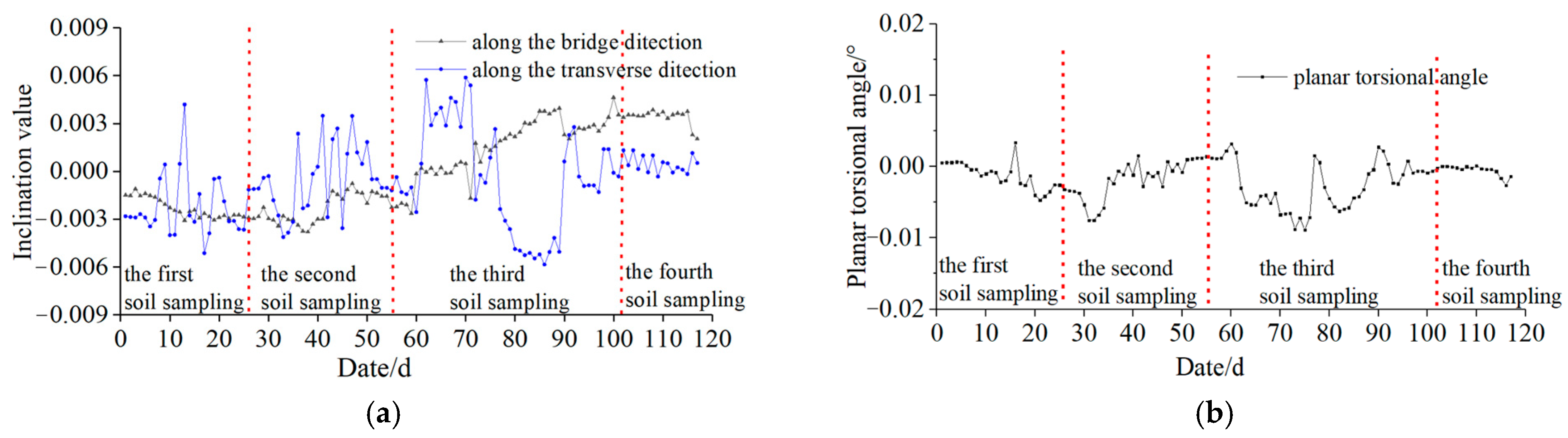
This project employed a bearing capacity calculation method that accounted for the 3D interaction between the caisson structure and the supporting soil, leading to precise evaluations of foundation strength. To address common issues such as structural cracking, tilting, and sand boiling during sinking, a “stepped progressive” control strategy was implemented for large-scale caissons. As a result, vertical alignment was consistently maintained within a tolerance of 1/150 throughout the construction process, with final verticality surpassing 1/2000, as illustrated in Figure 12a. Furthermore, the caisson’s final torsional angle was limited to just 0.07°, as shown in Figure 12b. It is far beyond the current control standards for verticality (1/100) and twist angle (1°) in the construction of caissons. These measures ensured a construction process that was safe, reliable, and of high quality.
Figure 12.
Inclination and planar torsional angle of the caisson: (a) inclination curves and (b) planar torsional angle curve.
6. Conclusions
This study investigated the interaction mechanisms between a large-scale caisson and the surrounding soil. The sinking behavior and active control strategies for such caissons were examined through a combination of theoretical analysis and numerical simulation. The proposed approach was subsequently validated in a practical engineering project. The main conclusions drawn from the study are as follows:
- (1)
- A simplified algorithm for evaluating end resistance was developed by assuming bilateral shear failure beneath the caisson and representing slip lines as segmented lines. The influence of excavation and burial at the caisson base on end resistance was analyzed. Based on these insights, calculation formulas were derived for end resistance under varying excavation angles and depths, as well as for different foundation embedment depths.
- (2)
- A correction coefficient, , was introduced to account for the 3D effects at various structural locations of the caisson foundation. Recommended values for are 1.0 for the cutting edges of the shaft wall and diaphragm walls, 1.8 for cross-shaped nodes, and 1.15 for T-shaped nodes.
- (3)
- The relative contributions of inclining and resisting moments to caisson alignment were found to vary with sinking depth. In the case of large-scale caisson construction, end resistance emerged as the dominant factor influencing the caisson’s orientation.
- (4)
- A “stepped progressive” control strategy for caisson sinking was proposed. This method enabled active regulation of both the width and burial depth of the supporting soil at the caisson base, effectively addressing common issues such as cracking and sand boiling. The method was successfully implemented in the sinking operation of Pier No. 5 of the Changzhou-Taixing Yangtze River Bridge, ensuring high precision and controllable construction performance.
Author Contributions
Conceptualization, H.Z. and D.L.; methodology, D.L.; formal analysis, Y.W.; investigation, F.J.; resources, D.L. and Y.W.; data curation, F.J.; writing—original draft preparation, D.L.; writing—review and editing, F.J.; project administration, H.Z.; funding acquisition, D.L. and Y.W. All authors have read and agreed to the published version of the manuscript.
Funding
This research was funded by the Hubei Natural Science Foundation Youth Project (Grant No. 2024AFB409) and the National Natural Science Foundation of China (Grant No. 42462029).
Data Availability Statement
All the research data can be obtained from this manuscript.
Conflicts of Interest
Author Hong ZHANG, De-jie Li and Fuquan JI were employed by CCCC Second Harbour Engineering Co., Ltd. Author De-jie Li was employed by CCCC Wuhan Harbour Engineering Design and Research Co., Ltd. The remaining authors declare that the research was conducted in the absence of any commercial or financial relationships that could be construed as a potential conflict of interest.
References
- Templeman, J.O.; Phillips, B.M.; Sheil, B.B. Cutting shoe design for open caissons in sand: Influence on vertical bearing capacity. Proc. Inst. Civ. Eng. Geotech. Eng. 2023, 176, 58–73. [Google Scholar] [CrossRef] [Scilit]
- Suppakul, R.; Chavda, J.T.; Jitchaijaroen, W.; Keawsawasvong, S.; Rattanadecho, P. Soft computing-based models for estimating undrained bearing capacity factor of open Caisson in heterogeneous clay. Geotech. Geol. Eng. 2024, 42, 5335–5361. [Google Scholar] [CrossRef] [Scilit]
- Keskin, M.S.; Laman, M. Model studies of bearing capacity of strip footing on sand slope. KSCE J. Civ. Eng. 2013, 17, 699–711. [Google Scholar] [CrossRef] [Scilit]
- Jiang, B.N.; Wang, M.T.; Chen, T.; Zhang, L.L.; Ma, J.L. Experimental study on the migration regularity of sand outside a large, deep-water, open caisson during sinking. Ocean Eng. 2019, 193, 45–53. [Google Scholar] [CrossRef] [Scilit]
- Lai, F.; Zhang, N.; Liu, S.; Sun, Y.; Li, Y. Ground movements induced by installation of twin large diameter deeply-buried caissons: 3D numerical modeling. Acta Geotech. 2021, 16, 2933–2961. [Google Scholar] [CrossRef] [Scilit]
- Zhang, J. Numerical simulation on the whole sinking process of open caisson with an improved SPH method. Math. Probl. Eng. 2021, 2021, 6699880. [Google Scholar] [CrossRef] [Scilit]
- Guo, M.; Dong, X.; Li, J. Study on the earth pressure during sinking stage of super large caisson foundation. Appl. Sci. 2021, 11, 10488. [Google Scholar] [CrossRef] [Scilit]
- Yan, X.; Zhan, W.; Hu, Z.; Xiao, D.; Yu, Y.; Wang, J. Field study on deformation and stress characteristics of large open caisson during excavation in deep marine soft clay. Adv. Civ. Eng. 2021, 2021, 7656068. [Google Scholar] [CrossRef] [Scilit]
- Yea, G.G.; Kim, T.H. Vertical cutting edge forces measured during the sinking of pneumatic caisson. Mar. Georesour. Geotechnol. 2012, 30, 103–121. [Google Scholar] [CrossRef] [Scilit]
- Sobhan, K. Principles of Geotechnical Engineering, 8th ed.; Cengage Learning: Boston, MA, USA, 2012; pp. 1–13. [Google Scholar]
- Royston, R.; Sheil, B.; Byrne, B.W. Monitoring the construction of a large-diameter caisson in sand. Proc. Inst. Civ. Eng. Geotech. Eng. 2022, 175, 323–339. [Google Scholar] [CrossRef] [Scilit]
- Zhou, X.; Zhang, X. Thoughts on the development of bridge technology in China. Engineering 2019, 5, 1120–1130. [Google Scholar] [CrossRef] [Scilit]
- Hoang, N.D. Image processing-based pitting corrosion detection using metaheuristic optimized multilevel image thresholding and machine-learning approaches. Math. Probl. Eng. 2020, 2020, 6765274. [Google Scholar] [CrossRef] [Scilit]
- Kong, X.; Li, J. Vision-based fatigue crack detection of steel structures using video feature tracking. Comput. Aided Civ. Infrastruct. Eng. 2018, 33, 783–799. [Google Scholar] [CrossRef] [Scilit]
- Gordan, M.; Razak, H.A.; Ismail, Z.; Ghaedi, K.; Tan, Z.X.; Ghayeb, H.H. A hybrid ANN-based imperial competitive algorithm methodology for structural damage identification of slab-on-girder bridge using data mining. Appl. Soft Comput. 2020, 88, 16–23. [Google Scholar] [CrossRef] [Scilit]

Disclaimer/Publisher’s Note: The statements, opinions and data contained in all publications are solely those of the individual author(s) and contributor(s) and not of MDPI and/or the editor(s). MDPI and/or the editor(s) disclaim responsibility for any injury to people or property resulting from any ideas, methods, instructions or products referred to in the content. |
© 2026 by the authors. Licensee MDPI, Basel, Switzerland. This article is an open access article distributed under the terms and conditions of the Creative Commons Attribution (CC BY) license.