


Abstract
A design framework is presented for broad-crested weirs with exponential (power-law) head–discharge behavior and three practical control-section shapes: Rectangular, parabolic, and triangular. Unlike ideal-flow sizing, the approach explicitly accounts for real-flow effects through a velocity coefficient at the control section. Starting from the energy equation and the critical-depth condition, analytical relations are obtained for the control-section depth, the critical depth, and the velocity and discharge coefficients. These relations are coupled with geometry-specific critical-flow expressions to derive a general, dimensionless design equation that links the required contraction ratio to the approach-velocity coefficient, the control-section velocity coefficient, and the head exponent n. The core innovation of the framework is a general dimensionless design equation that directly yields the required control-section area ratio /, i.e., the geometric contraction relative to the approach section, for a specified design head and approach-velocity condition. The method provides direct design parameters for each section family: Rectangular width, parabolic parameter, and triangular head angle. A short quantitative check against representative classical experimental ratios shows very good agreement with measured values. For the applied design example based on a trapezoidal approach section and conservative lower-bound values, neglecting real-flow effects underpredicts the required contraction ratio by about 28–39%, depending on the selected section shape. The developed framework provides a transparent, theoretically grounded, and practical tool for the hydraulic design of broad-crested weirs.
1. Introduction
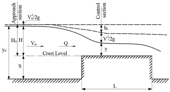
Broad-crested weirs and long-throated flumes are widely used as robust flow-control and flow-measurement structures in irrigation and drainage canals because a single upstream head measurement can be related to discharge through a well-defined control section operating near critical flow (Figure 1) [1,2,3,4,5]. Classical design guidance by Bos, Clemmens, and co-workers provides the foundation for practical sizing, but these methods are largely based on ideal-flow assumptions, geometry-specific charts, or coefficient corrections applied after the control geometry has already been selected [1,2,3,4,5,6,7]. However, practical broad-crested structures exhibit energy losses associated with entrance contraction, streamline curvature, and boundary-layer development on the crest. As a result, the control-section velocity coefficient deviates from unity, and the control depth becomes smaller than the critical depth under free overflow ( < ).
Figure 1.
Definition sketch for the flow over a broad-crested weir.
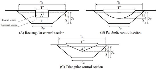
For an exponential family of control sections, the stage–discharge relationship can be written in power-law form , where is the head on the crest and depends on the control-section shape. In this study, three practical members of this family are considered: Rectangular (), parabolic (), and triangular ( as shown in Figure 2. Experimental measurements for rectangular, parabolic, and triangular broad-crested weirs reported by Abourehim confirm systematic departures from ideal assumptions and provide representative ratios for /, /, and (Table 1) [8,9,10]. Modern developments continue to refine broad-crested hydraulics, including analytical stage–discharge relationships for triangular broad-crested devices [11,12,13], numerical investigations of how coefficients vary with geometric parameters [14,15,16], and data-driven models for predicting discharge coefficients [17,18,19,20,21]. Although CFD and machine-learning approaches are powerful for detailed coefficient estimation, they generally require specialized numerical setups, calibration data, or training datasets and are therefore less convenient for rapid preliminary engineering design when a transparent closed-form sizing rule is desired. Standards for critical-depth flow measurement structures also formalize the concepts of a near-critical control section and modular (free-overflow) operation [22].
Figure 2.
Definition sketch for the approach and control sections.
Table 1.
Experimental values of /, /, and [8,9,10].
Despite these advances, there remains limited guidance on how to dimension exponential control sections while explicitly incorporating real-flow effects at the design stage. The present framework differs from classical design charts and recent CFD/data-driven studies by embedding the real-flow coefficients directly in a general contraction equation so that the geometry can be sized analytically rather than corrected only after selection or identified only through numerical/black-box models. This paper develops an energy-based analytical framework for broad-crested weirs with exponential sections under real-flow conditions, derives closed-form coefficient relations, and presents a general, dimensionless design equation linking the required contraction ratio / to the approach-velocity coefficient , the control-section velocity coefficient , and the exponent . The method yields direct design parameters for rectangular width, parabolic parameter, and triangular head angle, enabling straightforward practical application.
2. Materials and Methods
2.1. Assumptions and Range of Validity
This work assumes steady, one-dimensional flow between an approach section and a control section on the crest. The approach channel is prismatic, and the upstream head is measured sufficiently upstream of the crest to avoid local drawdown effects. At the control section, the pressure distribution is assumed hydrostatic, which is appropriate when the crest length is sufficient for near-parallel flow on the crest. Free overflow (modular operation) is assumed unless otherwise stated. Air entrainment is neglected, and adequate ventilation is assumed. Distributed friction losses between the approach and control sections are neglected; local entrance/contraction effects are represented using a velocity coefficient . Within the broad-crested range considered here, this assumption means that distributed along-path friction is treated as secondary to the local losses embedded in . For substantially longer crests, rough crest surfaces, or markedly non-uniform approach conditions, additional calibration of the total loss term may be required.
Broad-crested operation requires a sufficiently long crest. A practical classification places broad-crested behavior approximately within (equivalently, of order 2.5–10 for many applications), Figure 1, and modern numerical studies confirm that coefficients depend on head-to-length ratio and face slopes within this regime [11,15,16,17]. Accordingly, the assumption of negligible along-path friction should be regarded as most reliable inside this interval and may become less accurate outside it, especially for longer, rougher, or non-prismatic crest reaches. Users should verify the applicability of broad-crested and free overflow for the intended operating range.
2.2. Energy Equation and Velocity Coefficient
Using the crest level as datum (Figure 1) and applying the energy equation between the approach and control sections yields:
in which is the head loss at the control section due to flow contraction at the weir entrance, and is represented as in Equation (1), and taking the energy correction coefficient gives:
Defining the velocity coefficient which, under the present energy-loss definition, implies ≤ 1, and using yields:
The total head on the crest is ≈, where is the approach velocity.
2.3. Critical-Depth Relation
At the control section, the flow is assumed to pass through a critical state (). For an arbitrary cross-section, the critical-depth relation is
where and are the cross-sectional area and the top width in the critical condition.
2.4. Exponential Sections and Governing Equation for Control Depth
For the exponential family considered here, three practical control-section shapes are used: Rectangular (), parabolic (), and triangular (). Combining Equation (3) with the appropriate critical-flow expressions yields the following governing equations for the control depth .
2.4.1. Rectangular Section ()
For the rectangular shape and , accordingly , substituting for in Equation (3) gives,
2.4.2. Parabolic Section ()
The parabola equation is where P is the parabola parameter; therefore , and, accordingly, substituting for , in Equation (3), gives
2.4.3. Triangular Section ()
The triangular equation is where is the head angle of the triangle. Hence,, , and .
Based on the above quantities, , Substituting for , in Equation (3), gives
The Equations (5)–(7) can be written in a unified exponential form as
For free overflow (modular operation), the physically meaningful root satisfies ; the alternative root corresponds to submerged conditions (). For convenience in computation, Equation (8) may be expressed in dimensionless form using and .
2.5. Control-Section Depth y, Coefficients , , and Critical Depth
This subsection summarizes the relationships used to evaluate the velocity coefficient , the discharge coefficient , and the critical depth for broad-crested weirs with exponential control sections. The control-section depth is obtained from the general polynomial Equation (8). The physically relevant root is selected based on the flow regime: for free overflow (modular flow) and for submerged (drowned) conditions.
2.5.1. Rectangular Section
For , Equation (8) reduces to the cubic Equation (5). Applying Cardan’s method [23] yields the two physically meaningful roots for (free and submerged), given by Equations (9) and (10):
where the auxiliary angle is defined by:
The solution in Equation (9) satisfies and therefore represents free overflow, while Equation (10) yields and corresponds to submerged conditions. Using the above solution structure, and for the rectangular exponential section are expressed as:
or equivalently: where . The critical depth is:
2.5.2. Parabolic Section
For , Equation (8) yields the quartic Equation (6). Cardan’s procedure provides the relevant real roots for under free and submerged conditions, as given by Equations (15) and (16):
where:
The corresponding coefficient relations for the parabolic exponential section are:
or equivalently: , where . The critical depth is:
2.5.3. Triangular Section
For , Equation (8) leads to the quintic Equation (7), which does not admit a general closed-form analytical solution. Thus, the transformations leading from Equations (20)–(26) to the reduced dimensionless form remain exact analytical derivations, whereas the final determination of the control-section depth is obtained numerically from the reduced equation. Accordingly, by analogy with the values of and in both rectangular and parabolic shapes, the coefficients and for the triangular shape are:
From the critical-depth relation (4), the discharge at critical flow can be written as:
The corresponding weir equation is:
Equating the right-hand sides of Equations (22) and (23) gives:
Combining Equations (21) and (24) yields as a function of :
Or
Substituting Equation (24) into Equation (7) gives:
Substituting and from Equations (20) and (25) into Equation (26) yields the reduced form:
where for the free-overflow range. Equation (27) can be solved numerically (trial-and-error or standard root-finding) to obtain the control-section depth for free overflow, while the preceding coefficient and reduction steps remain analytical. The free-flow solution satisfies .
2.5.4. Unified Exponential-Form Coefficients (All Three Shapes)
The above shape-specific relations (Equations (12)–(14), (17)–(21) and (25)) can be expressed in a unified exponential form in terms of the exponent as follows:
The area of the flow cross-section at the control section can be expressed as:
Finally, the maximum and minimum limits for values of , , and are listed in Table 2. Physically, the lower end of each range corresponds to a more conservative, higher-loss control section, whereas = 1.0 represents the ideal-flow limit. When no calibration or experimental estimate is available, the lower-bound value may be used for conservative design.
Table 2.
Maximum and Minimum limits of , , and .
2.6. Governing Design Equation
Broad-crested weirs act as critical-depth controls by constricting the flow over the crest. Accordingly, the design can be expressed in terms of contraction ratios between the approach and control sections (Figure 2). This subsection derives a general, dimensionless sizing equation that relates the required area contraction to the approach-velocity coefficient , the control-section velocity coefficient , and the head exponent . The resulting equation directly supports the sizing of rectangular, parabolic, and triangular exponential sections.
The contraction ratios of area and top width are defined as the control-section area and top width relative to those at the approach section, i.e., / and , where the superscripts (*) and refer to the control and the approach sections, respectively.
The derivation starts from the critical-depth relation (Equation (4)) written for the control section: , where .
The total head , where . For readers more familiar with the traditional energy-head correction, the approach coefficient is simply the power-law representation of the same approach-velocity effect, because it relates the total head to the static head within the discharge form . The total head is related to the head on the weir crest using the approach-velocity coefficient as:
from which , Equation (32) gives:
For design, the control-section geometry is evaluated at the design head (Figure 2), taking the water-surface elevation at the approach and control sections as the same, i.e., . Accordingly, the relative area and top width are and .
Combining Equations (4) and (33) yields:
Substituting the expressions for , , and into Equation (34), the dimensionless design equation for the required contraction ratio becomes:
Equation (35) is the central result for practical design. Once is obtained, follows from . At , the corresponding top width is found from , where (rectangular), 2/3 (parabolic), and 1/2 (triangular).
2.7. Design Procedure (Algorithmic Steps)
- Select the weir family (exponent ): Rectangular (1.5), parabolic (2.0), or triangular (2.5).
- Specify design discharge and approach geometry; compute and at the approach depth .
- Compute approach velocity and velocity head ).
- Select a trial head on crest H and verify the broad-crested regime and modular operation for the intended range.
- Compute total head ).
- Compute approach coefficient (Equation (32)).
- Select (calibration if available; otherwise, conservative values within Table 2; for conservative sizing, use minimum).
- Compute from Equation (35), and then .
- Compute from with = 1, 2/3, or 1/2 for rectangular/parabolic/triangular sections.
- Compute geometry parameters: Rectangular width ; parabolic parameter ; triangular head angle . Verify under free overflow and iterate if needed.
3. Results
3.1. Quantitative Check Using Representative Experimental Ratios
A short quantitative check is performed using the representative experimental ratios in Table 1. First, is predicted from Equation (28) using measured and compared to the reported . Second, is predicted from Equation (30) using the reported . Third, is predicted by solving Equation (8) for using the reported and (free-overflow root ). Across the three representative points, the mean absolute percentage error (MAPE) is 2.00% for , 2.13% for , and 5.21% for . Detailed values are reported in Appendix A (Table A1). These representative checks are consistent with the classical broad-crested design ranges reported by Bos and Clemmens et al. [2,3,4], although those references primarily provide design guidance rather than a single harmonized raw experimental dataset for direct point-by-point cross-validation across all three exponential shapes.
3.2. Applied Design Example (Real-Flow Sizing)
Design data: ; trapezoidal approach channel with bottom width , side slopes , and upstream depth , so and . The approach velocity is and ) = 0.018 m. For conservative sizing, the minimum admissible values from Table 2 are adopted for each shape. Table 3 summarizes a representative solution procedure and the resulting control-section dimensions.
Table 3.
Solution procedure based on real flow assumptions.
3.3. Ideal-Flow Versus Real-Flow Contraction
To quantify the impact of ideal-flow assumptions, the contraction ratio is recomputed with while keeping other quantities unchanged. Table 4 compares ideal-flow and real-flow contraction ratios.
Table 4.
Comparison between ideal and real flow assumptions for evaluating .
4. Discussion
4.1. Sensitivity and Uncertainty
Equation (35) implies that, for fixed n and , the contraction ratio scales approximately as . Therefore, a ±5% uncertainty in produces approximately a ∓10% change in the required contraction ratio. Table 5 reports this sensitivity for the applied example.
Table 5.
Sensitivity of the design area ratio to uncertainty in (±5%) for the applied example.
4.2. Extension of the Applied Design Example Using Recent Numerical Coefficients
Modern numerical studies often report discharge and velocity-related coefficients that vary with crest geometry. To keep the present paper design-oriented, Table 6 is used only as an extension of the applied example, not as a primary validation dataset. It illustrates how recent numerical coefficients reported by Demirçelik et al. (2025) [15] for a rectangular broad-crested weir and several modified geometries may be inserted into the present framework. Using Equation (32) with = 1.5, is computed from , and Equation (35) is then used to compute an implied contraction ratio .
Table 6.
Example of integrating CFD-based coefficients into Equation (35) computed from the data of Demirçelik et al. (2025) [15] for = 1.5.
As coefficient definitions are not uniform across literature, the values listed in Table 6 should not automatically be interpreted as the same energy-based defined in Equation (3). Some reported values exceed unity because they function as study-specific numerical or velocity-related factors rather than as the loss-based coefficient adopted in the present manuscript. Accordingly, the coefficient definition should be checked before direct use in Equation (35).
Although the coefficient definitions and boundary conditions are study-specific, the exercise demonstrates a practical pathway: Coefficients obtained from recent CFD/experimental studies can be used directly as inputs to Equation (35) only after their definitions are reconciled with the present energy-based framework. When an external study reports only discharge coefficients or alternative velocity factors, a practical correction is to back-calculate an equivalent energy-based coefficient from the reported head–discharge relation before inserting it into the design equation. Conversely, changes in reported coefficients in modern studies can be interpreted as changes in the required opening area, which is useful for performance-based design and uncertainty assessment.
4.3. Limitations and Applicability
The formulation is intended for steady, one-dimensional free overflow over a smooth, broad crest within the broad-crested validity range. For non-prismatic channels, the same framework may still be used if the approach section is defined locally and the corresponding , , and are evaluated consistently, but additional calibration of approach losses may be needed. Rough or vegetated crests, submerged flow, and strongly non-uniform approach conditions require a modified loss representation or separate calibration of and . Future work should therefore target broader experimental datasets, explicit submergence corrections, and calibration procedures for rough and non-prismatic control sections. These extensions would improve the transfer of the framework from idealized hydraulic design to a wider range of field conditions.
5. Conclusions
A unified analytical framework was developed for designing broad-crested weirs with exponential head–discharge behavior for three practical control-section families (rectangular, parabolic, triangular). Starting from the energy equation and critical-depth condition, closed-form relations were obtained for , , , and , and consolidated into a general dimensionless design equation linking the contraction ratio to approach effects (), real-flow losses (), and exponent n. A short quantitative check using representative experimental ratios yields MAPE values of about 2% for and and about 5% for . In the applied design example, ideal-flow sizing () underpredicts the required contraction ratio by about 39.0% for the rectangular section, 34.3% for the parabolic section, and 28.2% for the triangular section, indicating that the sensitivity to real-flow effects is strongest for the rectangular case and lowest for the triangular case among the three shapes considered. Sensitivity results show that is a dominant uncertainty driver; conservative selection or calibration is recommended when high accuracy is required.
Author Contributions
Conceptualization, A.M.A. and M.A.A.; methodology, A.M.A. and M.A.A.; formal analysis, A.M.A. and M.A.A.; investigation, A.M.A. and M.A.A.; writing—original draft preparation, A.M.A. and M.A.A.; writing—review and editing, A.M.A.; supervision, M.A.A. All authors have read and agreed to the published version of the manuscript.
Funding
This research received no external funding.
Data Availability Statement
The original contributions presented in this study are included in the article. Further inquiries can be directed to the corresponding author.
Acknowledgments
The authors would like to thank Prince Sultan University for paying the Article Processing Charges (APC) for this publication.
Conflicts of Interest
The authors declare no conflicts of interest.
Abbreviations
The following abbreviations are used in this manuscript.
| Flow cross-sectional area at the control section | |
| Flow cross-sectional area at the control section when | |
| Flow cross-sectional area at the approach section | |
| Flow cross-sectional area of critical flow | |
| Bed width of the approaching channel | |
| Discharge coefficient | |
| Approach-velocity coefficient | |
| Control-section velocity coefficient | |
| Gravitational acceleration | |
| Head on the weir crest | |
| Total head on the crest | |
| Local head loss between approach and control section | |
| Crest length | |
| Exponent in the head–discharge relationship | |
| Parameter of the parabolic shape | |
| Flow rate (discharge) | |
| Crest height | |
| Top width at the control and approach sections | |
| Top width at the control section when | |
| Top width at critical flow | |
| Velocities at the control and approach sections | |
| Depths of flow at the control and approach sections | |
| Critical depth | |
| Energy correction coefficients | |
| Head loss coefficient | |
| Geometric factor in | |
| Head angle of the triangular shape | |
| auxiliary angle |
Appendix A
Table A1.
Predicted versus representative experimental values using Table 1.
References
- Bos, M.G.; Replogle, J.A.; Clemmens, A.J. Flow Measuring Flumes for Open Channels Systems; John Wiley and Sons: New York, NY, USA, 1984. [Google Scholar]
- Bos, M.G. Long-Throated Flumes and Broad-Crested Weirs; Martinus Nijhoff/Dr. W. Junk Publishers: Dordrecht, The Netherlands, 1985. [Google Scholar]
- Clemmens, A.J.; Bos, M.G.; Replogle, J.A. Contraction ratios for weirs and flumes designs. J. Irrig. Drain. Eng. (ASCE) 1987, 113, 420–424. [Google Scholar] [CrossRef] [Scilit]
- Clemmens, A.J.; Bos, M.G. Critical depth relations for flow measurements design. J. Irrig. Drain. Eng. (ASCE) 1992, 118, 640–644. [Google Scholar] [CrossRef] [Scilit]
- Clements, A.J.; Replogle, J.A.; Bos, M.G. Rectangular measuring flumes for lined and earthen channels. J. Irrig. Drain. Eng. (ASCE) 1984, 110, 121–137. [Google Scholar] [CrossRef] [Scilit]
- Doering, H.A.; Barker, C.L. Pressure momentum theory applied to the broad-crested weir. Trans. ASCE 1941, 106, 1719–1732. [Google Scholar]
- Rao, S.S.; Shulko, M.K. Characteristics of flow over weirs of finite crest width. J. Hydraul. Div. (ASCE) 1971, 97, 1807–1816. [Google Scholar] [CrossRef] [Scilit]
- Abourehim, M.A. Depths of flow over rectangular broad-crested weir. Alex. Eng. J. 1991, 30, C55–C62. [Google Scholar]
- Abourehim, M.A. Characteristics of flow over parabolic broad-crested weir. Alex. Eng. J. 1994, 33, C125–C139. [Google Scholar]
- Abourehim, M.A. Flow over triangular broad-crested weir. Alex. Eng. J. 1995, 34, C23–C31. [Google Scholar]
- Achour, B.; Amara, L. Flow measurement using a triangular broad crested weir: Theory and experimental validation. Flow Meas. Instrum. 2022, 83, 102088. [Google Scholar] [CrossRef] [Scilit]
- Nicosia, A.; Ferro, V. A new approach for deducing the stage-discharge relationship of a triangular broad-crested device. Flow Meas. Instrum. 2022, 85, 102160. [Google Scholar] [CrossRef] [Scilit]
- Nicosia, A.; Carollo, F.G.; Di Stefano, C.; Ferro, V. New stage-discharge relationship for triangular broad-crested weirs. Water 2022, 14, 2993. [Google Scholar] [CrossRef] [Scilit]
- Malekzadeh, F.; Salmasi, F.; Abraham, J.P.; Arvanaghi, H. Numerical investigation of the effect of geometric parameters on discharge coefficients for broad-crested weirs with sloped upstream and downstream faces. Appl. Water Sci. 2022, 12, 110. [Google Scholar] [CrossRef] [Scilit]
- Demirçelik, A.; Duman, M.M.; İkincioğulları, E. Numerical investigation of flow characteristics of broad-crested weirs with different geometry. Int. J. Eng. Res. Dev. 2025, 17, 247–256. [Google Scholar] [CrossRef] [Scilit]
- Amin, J.; Mehmood, K.; Ghani, U. Numerical study of flow characteristics over a compound rectangular broad crested weir. Flow Meas. Instrum. 2025, 102, 102835. [Google Scholar] [CrossRef] [Scilit]
- Simsek, O.; Gumus, V.; Ozluk, A. Prediction of discharge coefficient of the trapezoidal broad-crested weir flow using soft computing techniques. Neural Comput. Appl. 2023, 35, 17485–17499. [Google Scholar] [CrossRef] [Scilit]
- Nouri, M.; Sihag, P.; Kisi, O.; Hemmati, M.; Shahid, S.; Adnan, R.M. Prediction of the discharge coefficient in compound broad-crested-weir gate by supervised data mining techniques. Sustainability 2023, 15, 433. [Google Scholar] [CrossRef] [Scilit]
- Shen, G.; Cao, D.; Parsaie, A. Discharge coefficient prediction and sensitivity analysis for triangular broad-crested weir using machine learning methods. River 2024, 3, 316–323. [Google Scholar] [CrossRef] [Scilit]
- Shadkani, S.; Mohammadi Sergini, M.; Malekzadeh, F.; Saber, A.; Kabiri, N.; Goodarzi, A.; Pak, A. A hybrid hydrodynamic particle simulation methodology for discharge coefficient prediction of broad-crested weirs. Flow Meas. Instrum. 2025, 102, 102806. [Google Scholar] [CrossRef] [Scilit]
- Doustkam, M.; Rahmanshahi, M.; Fathi-Moghadam, M.; Keramat, A.; Duan, H.-F. Experimental study on the hydraulic performance of porous broad-crested weirs with sloping crests. Water Resour. Manag. 2024, 38, 4783–4802. [Google Scholar] [CrossRef] [Scilit]
- ISO 4359:2022; Flow Measurement Structures: Rectangular, Trapezoidal and U-Shaped Flumes. 3rd ed. International Organization for Standardization: Geneva, Switzerland, 2022.
- Korn, G.A.; Korn, T.M. Mathematical Handbook for Scientists and Engineers; McGraw-Hill: New York, NY, USA, 1968. [Google Scholar]

Disclaimer/Publisher’s Note: The statements, opinions and data contained in all publications are solely those of the individual author(s) and contributor(s) and not of MDPI and/or the editor(s). MDPI and/or the editor(s) disclaim responsibility for any injury to people or property resulting from any ideas, methods, instructions or products referred to in the content. |
© 2026 by the authors. Licensee MDPI, Basel, Switzerland. This article is an open access article distributed under the terms and conditions of the Creative Commons Attribution (CC BY) license.