


Abstract
Besides the purification process in the wastewater treatment plant that includes mechanical, biological, and chemical approaches, analysis of hydraulic behavior is also fundamental. This means developing a digital replica of the physical process by simulating the hydraulic parameters. Studying fluid behavior in the plant enables process optimization, improves plant behavior, prevents equipment malfunctions, and more. This paper focuses on defining the concept of a wastewater treatment plant prototype, simulating it, and identifying the available and most suitable software that enables efficient process simulation and validation. The hydraulic parameters, as per the literature review and the proposed concept, that will be simulated are pressure, flow, pressure drop, and water level. MATLAB/Simulink and Python programming languages are considered the most suitable software/programming languages for hydraulic parameters simulation.
1. Introduction
Water resources are rapidly becoming deficient, resulting in water scarcity emerging as one of the defining environmental challenges of the 21st century. Urbanization, industrial expansion, and agricultural production have led to an increased demand for water, while climate variability continues to stress existing freshwater resources [1]. In consequence, sustainable management and reuse of water have become global priorities, with wastewater treatment plants (WWTPs) playing a critical role in protecting both public health and the environment. WWTPs are engineered systems designed to collect, treat, and discharge or reuse municipal and industrial wastewater, thereby reducing pollution loads and enabling water recycling for non-potable applications [2]. A combination of mechanical, physical, chemical, and biological processes is applied to remove pollutants from the incoming wastewater [3]. WWTPs handle highly variable hydraulic loads driven by diurnal patterns, industrial discharges, and storm events. As urbanization increases, wastewater networks are more necessary in modern urban areas to manage growing wastewater demands from residential, sanitary, and industrial sources. Modern WWTPs are expected not only to treat wastewater effectively but also to operate as resource recovery facilities, integrating energy efficiency, nutrient recovery, and water reuse strategies in line with circular economy principles [4]. The hydraulic performance of WWTPs plays a vital role in meeting the newly imposed sustainability requirements.
Hydraulics governs how water, sludge, and air are conveyed through the complex networks of pipes, pumps, valves, storage tanks, clarifiers, and aeration channels, thus influencing process stability, energy consumption, and treatment efficiency. Inefficient hydraulic design or operation can result in short-circuiting, uneven flow distribution, pump cavitation, or sediment accumulation. Therefore, hydraulic modeling is an essential part of both the design and operation of WWTPs, enabling engineers to simulate, predict, and optimize flow conditions under various scenarios before physical implementation. Moreover, developing reliable hydraulic models supports the transition toward smart and adaptive water infrastructure.
Despite substantial advances in biological and chemical modeling, hydraulic simulation within WWTPs remains underexplored. This review aims to address this lack of overview of integrated studies that analyze hydraulic performance as profoundly as the biological and chemical processes in WWTPs by consolidating the state of knowledge on hydraulic modeling tools and their applications in both municipal and industrial WWTPs. Emphasis is placed on numerical approaches, including one-dimensional flow solvers (PipeFlow, EPANET, AFT Fathom, AFT Impulse, AFT Arrow), computational fluid dynamics (CFD) techniques, and MATLAB/Simulink-based modeling frameworks that enable process optimization and predictive operation. By synthesizing peer-reviewed research and practical case studies, the review outlines current capabilities, limitations, and emerging opportunities for hydraulic modeling to enhance the performance and sustainability of modern wastewater treatment systems.
The paper is structured as follows. Section 2 reviews the main categories of hydraulic modeling approaches and software tools, including one-dimensional network solvers, MATLAB/Simulink-based simulation frameworks, and CFD models. The utilization of the software for analyzing WWTPs is demonstrated through case studies. Section 3 describes the developed concept of a hydraulic model for a WWTP, providing an overview of the fundamental hydraulic principles governing flow transport within the WWTP on which the modeling is based, and emphasizing the parameters that influence hydraulic behavior. Finally, Section 4 concludes the paper by summarizing the main findings and proposing directions for future research in hydraulic modeling of WWTPs.
2. Literature Review
2.1. Available Approaches in the Modeling of WWTP in MATLAB/Simulink
WWTPs rely on complex fluid transport systems consisting of pipes, pumps, valves, and tanks to convey water, sludge, and gases between process units. Since its emergence in the mid-1990s, the application of mathematical modeling and simulation in WWTPs has gained growing popularity to support the selection of suitable design parameters [5]. Thus, modeling hydraulic processes in WWTPs is critical for their design and operation, helping to ensure required flow distribution, efficiency, and protection against water hammer. Fluid flow in pipelines and pumping units of WWTPs can be analyzed using various modeling tools and techniques [6].
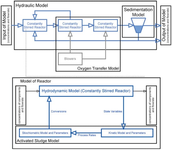
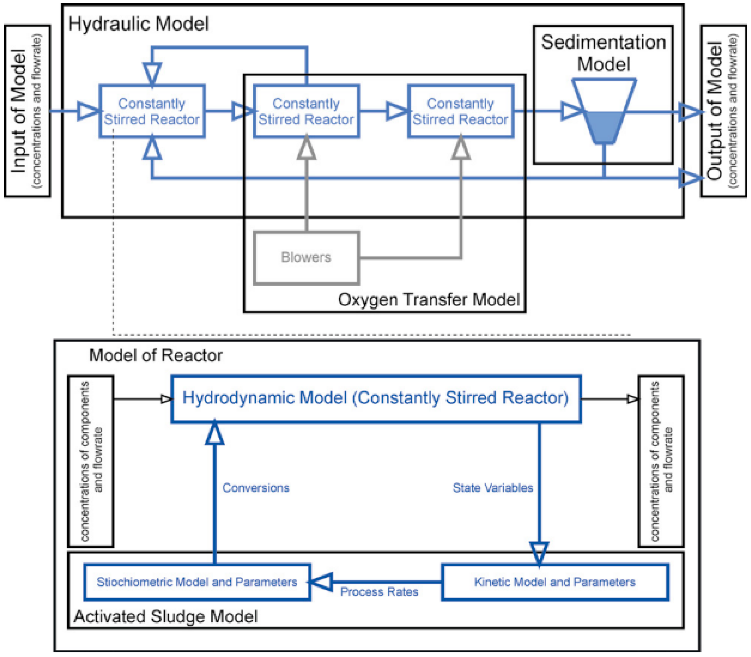
Several methods for purifying wastewater exist, including mechanical, biological, physicochemical, and chemical processes. Most harmful substances contained in wastewater can be removed by mechanical treatment. In [7], a new mathematical model for calculating vertical sediments in local wastewater treatment facilities for small enterprises has been introduced. The model was based on molecular kinetic theory, focusing on improving design parameters and achieving high filtration efficiency. Improving the efficiency of the WWTP in industrial and residential areas is essential. More efficient results can be achieved by developing precise models, executing controlled experiments, and performing detailed calculations. This approach helps predict both technical performance and economic feasibility, leading to a more efficient water purification process. Experimental measurements and tests later confirmed that the approach works as intended. Also, a vertical filter model backed by computational analysis, a solution that balances cost and performance, is developed, making the system suitable for industries and small communities alike. The developed model enables the existence of customized sprinkler systems for different water flow rates. This leads to system adaptability improvement and speeds up construction, helping the projects finish faster without sacrificing quality. The importance of WWTP efficiency during design and operation is introduced in [8]. There, the need for numerical modeling to predict and optimize treatment processes under varying conditions is represented. In this paper, the focus is on making a real-time analysis of water treatment efficiency. Further, reference [9] focuses on developing a mathematical model for industrial wastewater treatment using ion exchange resins. It was tested at the Kungrad soda plant, achieving a cleaning efficiency of up to 98–99%. The focus of this paper is on developing a mathematical model using a stoichiometric matrix method. MATLAB/Simulink is used for constructing concentration change graphs. Another paper that represents the modeling of the treatment processes is described in [10]. The paper represents the development of a water treatment process linear model for dynamic control. Estimating unknown parameters for controlling wastewater treatment processes, by using a Luenberger observer and a Kalman filter, is implemented to provide better water quality and energy efficiency. According to [11], the methane flow and effluent chemical oxygen demand (COD) concentration can be accurately predicted by using an Anaerobic Digestion Model (ADM) if the measured data are quality data sets. Also, the validation model can predict full-scale sludge digester performance under dynamic loadings and optimize methane production at different operating conditions. The simulation and validation are made using a limited number of monitored parameters. Model calibration is made using a long-term data set. The validation model is made with measured data from the full-scale sludge digester. In [12], Monte-Carlo simulation is represented by using the Sobol and easyGSA tools for modeling the temperature (T), nitrate (NO3−), and ammonium (NH4+) that have the highest total impact on liquid N2O emissions in WWTP. Despite the modeling of chemical and biological processes, there are some papers about chemical dosing control. In [13], the non-linear modeling and estimation of a coagulant dosage system for water treatment plants developed using Hammerstein–Wiener models is described. The most suitable model configuration was selected and linearized at an estimated operating point. The proposed model configuration showed remarkable improvement over other models and is compatible with widely used industrial controllers for improved automatic control. Also, references [14,15] represent coagulant dosage modeling with a different methodology. According to [16], the paper applies Simulink for dynamic modeling of activated sludge processes as a part of biological wastewater treatment. Equilibrium between biomass and organic matter is reached after 200 days during dry weather. Rain episodes lead to a decrease in biomass, an increase in organic matter, and significant bacterial growth. Using Simulink for modeling the biological wastewater treatment process in the aerator tank was also undertaken [17,18]. Proposed models and limitations are analyzed to improve control strategies for wastewater treatment. Simulating the aeration system of WWTP to design and optimize aeration control according to [19]. In [20], the paper presents the modeling methods for WWTP to improve process understanding and propose improvements. It highlights the use of analytical models and alternative methods like neural networks for capturing biological and physical processes. The proposed models are represented in Figure 1.
Figure 1.
Analytical models of WWTP. Reprinted/adapted with permission from Ref. [20]. 2022, Stepan Ozana.
Wastewater process modeling provides options for upgrades, new plant design, and operational improvements. Software packages like BioWin, GPS-X, and Aqua Designer are used to solve simulated equations and propose solutions for specific facilities since wastewater process models are very important in understanding and upgrading the processes. The combination of wastewater process modeling with computational fluid dynamics enables the comprehensive testing and examination of flow characteristics and biological, physical, and chemical aspects [21].
MATLAB/Simulink is usually the most used software for the simulation of different processes and scenarios. In [22], the development of hydrologic and water quality models is represented. There, a stormwater runoff model and a finite-volume-based water quality model were developed using Simulink for teaching and research purposes. The models are intended for use in teaching graduate-level courses in hydrology and stormwater modeling. In stratified natural water systems, a finite volume, multi-layer pond model was developed in Simulink. Its purpose was to simulate eutrophication dynamics. It represented a new application of the platform. Also, in another paper [23], the researchers implemented Simulink to create a tank model for rainfall–runoff simulation, showcasing its capabilities in hydrological modeling. The software’s graphical interface and modular design made the model easy to comprehend and adapt. Their work confirmed that Simulink serves as an intuitive yet powerful tool for building hydrological models and analyzing water systems. There are a few old papers that describe hydraulic modeling in a water treatment plant [24,25].
To describe which parameter has the strongest impact on the output change, a sensitivity analysis is described using a few hydraulic parameters that affect the hydraulic behavior of the model system. The selected parameters will include the inflow rate (Qi), which determines the entering water volume in the system. It will strongly affect the water level and downstream flow. Pump head–flow characteristics influence pressure buildup, achieved flow rate, and system response under different operating conditions. Valve discharge coefficient is going to control flow regulation and contribute to local energy losses. Pipe friction coefficient and pipe roughness affect the pressure drop along the pipeline and the overall head required by the pump. Another parameter could be the water loss coefficient, which represents unpredicted losses that affect mass balance accuracy and the tank-level prediction.
2.2. Available Approaches in the Modeling of WWTP in Software for 1D Fluid Flow Simulation
By implementing basic tools, steady-state flow in pipelines can be modeled and simulated by solving the mass and energy conservation in pressurized pipe networks to predict flow rates, pressure, and losses. Such tools include EPANET, AFT Fathom, and PipeFlow Expert, which are widely used for sizing pumps and pipes and evaluating network configurations.
Pipe Flow Expert is a software that computes flow distribution and pressure drops under steady state conditions, supporting complex looped systems with multiple pumps, multiple supply tanks, and multiple discharge points. It includes extensive libraries for fluids and fittings. The software enables up to nine different fluid zones (segments with distinct fluid properties) in one model, allowing the analysis systems to handle sections of differing liquids, but it does not handle multiphase mixtures. Pipe Flow Expert is used in industries ranging from petrochemical to water/wastewater [26]. Even though there are no documented case studies of applying PipeFlow in WWTPs, engineers can use it to size pumps and pipes for sludge recirculation, chemical feed lines, effluent pipelines, to evaluate head loss, and for simple capacity issues. However, due to the inability to simulate time-varying flows, PipeFlow is limited for use in operation and retrofit.
EPANET is a free and open-source software developed by the United States Environmental Protection Agency that performs steady-state and extended-period simulations (EPS) of flow and water quality in pressurized networks, modeling pipes, pumps, valves, and tanks to calculate fluid flow in pipelines and pressure at nodes [27].
However, EPANET does not have features for open channels, sludge, or gas systems, making its WWTP-specific use limited to modeling the clean water side and pumping systems, thus supporting design tasks. Lacking the ability to model pressurized transients or internal WWTP hydraulics limits its value in renovation scenarios. In [28], it was analyzed how greywater reuse affects sewer conveyance in a residential complex. Modeling the water distribution network using EPANET, looking at pressures at junctions and flows in pipes of the domestic water network, meant that the pumps’ energy requirements were obtained. In [29], EPANET 2 was applied to model dual distribution systems that incorporate greywater, rainwater, and treated wastewater to meet non-potable needs for single-family residences, buildings, and communities to evaluate infrastructure demands. The pipeline diameters, the storage tanks’ capacities, and the pumping requirements were determined for three water reuse scenarios. In [30], EPANET was used to model a reclaimed water distribution system at the University of Texas at Austin, which receives treated effluent from Walnut Creek and South Austin Regional WWTPs in Austin, Texas, USA. The embedded energy was calculated for two different water sources: drinking water and reclaimed water for non-potable applications, to support the idea that water reuse can enable energy savings compared to conventional systems for drinking water distribution. In [31], a pipe network was modeled for Beijing, integrating multiple WWTPs to support planning for the utilization of reclaimed water. The hydraulic model is based on EPANET and a geographic information system (GIS). The simulation results were used to adjust the pipeline distribution system so that it meets the reclaimed water demand. In [32,33], a reclaimed water distribution system supplied by Portuguese wastewater resource recovery facilities (WRRFs) was modeled. The hydraulic networks were constructed in EPANET and coupled with the EPANET-MSX extension to capture disinfectant decay processes, thus representing reclaimed water quality behavior of water networks fed by WWTP effluent. The models were calibrated against field measurements, ensuring that the simulated residual concentrations matched observed data. Even though uncalibrated models can show significant discrepancies, field-based EPANET studies confirm that calibration substantially improves performance. The study [34] which uses EPANET 2.2 demonstrated that adjusting Hazen–Williams roughness coefficients to account for pipe aging eliminated statistically significant differences between simulated and observed pressures and achieved a strong correlation (R = 0.967), while reference [35] further showed that EPANET enhanced with genetic algorithm optimization yields improved agreement with measurements, achieving a correlation coefficient of 0.90 and a standard prediction error of 8.93% over 24-h simulations.
While EPANET is not typically used for modeling internal hydraulics of WWTP processes, the literature review shows its relevance in outflow and reuse modeling, especially in contexts where treated wastewater or greywater is repurposed and distributed.
AFT Fathom [36] is a steady-state incompressible flow modeling software, enabling simulation of flows, pressures, head losses, and energy usage in piping networks that include components like pumps, valves, fittings, and tanks. It supports modeling of both Newtonian and non-Newtonian fluids. Addressing deposition and slurry behavior, it can model the effects of pumping fluids containing settling solids.
Fathom is widely suited to both preliminary design and detailed hydraulic evaluation in municipal and industrial applications. AFT Fathom has also been applied to hydraulic modeling of liquid systems within wastewater treatment plants, particularly for sludge handling and thermal recirculation networks.
In a major WWTP expansion in the San Francisco area, a new Thermally Hydrolyzed Sludge (THS) system and five digesters were added. AFT Fathom was used to simulate the distribution of THS via flow control valves to four parallel digesters, maintaining balanced flows. The model also encompassed the digested sludge (DS) cooling loop with variable speed pumps delivering ~86 m3/h through heat exchangers. Both THS (diluted to ~10% solids at ~74 °C) and digested sludge were modeled as non-Newtonian fluids using power law rheology. Besides the sludge’s thermophysical properties, input parameters such as pipe dimensions and lengths, pump curves, and valve characteristics were defined. Operational constraints like required flow rate of 27–30 m3/h, minimum velocity requirements of 1 m/s to prevent solids settling, and minimum temperature of ~74 °C for THS circulation were incorporated. Based on these inputs, the model supported a series of optimization schemes, including scenario testing of pump speeds, THS/DS mixing ratios, and control valve positions. Pump speeds were varied between 40 and 87%, and flow control valves were adjusted to maintain consistent digester feed flows of approximately 19 m3/h per unit. The THS loop was evaluated under high-solids, low-solids, and mixed-flow conditions, with loop flow rates ranging from 62 to 104 m3/h. Such scenario testing ensured that the system could accommodate thermal and hydraulic variations without exceeding pump or valve operating limits. The main results are practically applicable since the accurate sizing of pipes, pumps, and control valves for the digester feed and cooling system provided uniform flow distribution to the four primary digesters and adequate velocities, while preventing sludge settling and sustaining the cooling and heating loops under all expected operating scenarios [37]. In another case [38], AFT Fathom was used to analyze the heat reservoir recirculation loop of a digester complex in a wastewater reclamation plant, where hot water from boilers was circulated through heat exchangers to maintain digester temperature. Both hydraulic and thermal behavior of the loop, including convective heat loss to surroundings, were simulated, while incorporating equipment such as piping, pumps, boiler systems, heat exchangers, and insulation. The main aim was to determine if existing heat reservoir recirculation pumps could deliver the minimal required flow to the heat reservoir loop to maintain the loop temperature. The AFT model validated existing pump capacity and control valve setpoints at the same time, demonstrating that the system could meet seasonal heating demands with high accuracy. In Singapore’s NEWater project, CH2M Hill engineers used AFT Fathom to model the hydraulic distribution of reclaimed effluent produced at a water reclamation plant [39]. The model included flows from the plant treatment train to the solids handling building, anaerobic digesters, and influent pump station, verifying they would receive adequate flow and pressure under different operating conditions. By testing pump curves, pipe diameters, and valve configurations in Fathom, it was confirmed that the reclaimed water network could meet demand without redesigning major components. Besides pipes and pumps sizing, the model also allowed simulation of operating scenarios such as varying effluent flows between digesters and solids processing units to predict system behavior at both normal and peak demand. In the Hydrus Works stormwater system project [40], AFT Fathom was used to model a refinery drainage and lift station network conveying stormwater (clean water with standard liquid properties) through a system of 505 interconnected pipes, 4 pump stations, multiple control valves, and elevation-driven gravity segments. The modeling parameters applied were pump curves, pipe diameters and lengths, fitting losses, and elevation data. Using 160,000 field measurement points, hydraulic resistance and pump operation were calibrated within 3% of measured performance. The optimization scheme used AFT Fathom built-in tools Scenario Manager and Goal Seek & Control to automatically test low-, medium-, and high-investment alternatives by adjusting pump sequencing, valve positions, and pipeline routing. Scenario testing resulted in options that improved overall conveyance capacity by up to 151%, removed critical hydraulic problems, and verified safe operating pressures throughout the system. The calibrated model identified a way to deliver the same hydraulic performance as the client’s original concept but reduced projected capital costs (a 35% savings, or USD 25 million), while demonstrating that the redesigned stormwater network could withstand major Gulf Coast storms, operate pumps safely, and maintain required water levels in all main drainage paths. In an industrial application, a calibrated AFT Fathom model of a nuclear plant service water system reproduced measured flow rates with average relative errors of 1–2.3% and pressure differences within 1.2–1.7 psig, using automated Goal Seek and Control routines to adjust effective pipe roughness and diameters [41].
AFT Arrow is a steady-state compressible flow modeling software developed by Applied Flow Technology designed for gas and air systems, accounting for pressure, temperature, density, heat transfer, choking, and compressibility effects across a piping network [42]. Users can model pipes, fittings, valves, heat exchangers, compressors, blowers, and other equipment, with results including pressures, velocities, Mach numbers, flow rates, and energy requirements.
By including compressible flow analysis in the design process, WWTP engineers can better integrate aeration and gas handling systems with the overall plant hydraulics.
In wastewater treatment plants, AFT Arrow has been applied primarily to aeration systems and digester gas piping [43]. For aeration, it enables engineers to simulate blower performance and distribution piping to ensure reliable oxygen delivery while avoiding surge conditions. For digesters, Arrow is used to evaluate biogas collection, storage, and flaring systems, confirming that pipelines and relief valves can safely accommodate production scenarios.
AFT Arrow was used to model the aeration system of a 64 MGD wastewater treatment plant undergoing a major retrofit of 11 blowers and associated air piping [44]. The plant had been experiencing blower surge events during hot weather, creating operational risks during phased construction when aeration tanks had to remain online. The entire aeration network was modeled in Arrow, applying input parameters such as blower performance curves, air manifold layout, pipe diameters, elevations, and air properties. Based on these inputs, the optimization scheme evaluated multiple construction-phase and operational scenarios, including testing whether the blower discharge pressure setpoint could be safely reduced from 0.55 bar to 0.50 bar; model results confirmed this reduction was feasible while simultaneously increasing total air flow by 48,800 Nm3/h, equivalent to 2.5 additional blowers of effective capacity. These simulations also guided decisions on the sequence in which aeration tanks could be taken offline and replaced while keeping the plant fully operational. The practical application effects were substantial: lowering the pressure setpoint eliminated seasonal surge risk during hot weather, improved operational stability, ensured adequate aeration supply to all tanks during phased construction, and generated USD 200,000–600,000 in avoided capital and installation costs by removing the need for new equipment [44].
At the Sunriver Wastewater Treatment Plant upgrade in Oregon, AFT Arrow was employed to optimize two critical aeration air networks: one for scouring membrane bioreactors and another for sludge basin mixing. The tool was used to model alternative blower configurations and control strategies, ensuring that standalone and future expansion scenarios were adequate from a hydraulic aspect [45]. The Arrow model contributed to efficient duct sizing, reliable standby blower integration, and performance evaluation under variable conditions.
These case studies demonstrate the value of Arrow for evaluating sizing, equipment selection, and construction sequencing scenarios in WWTP aeration systems.
AFT Arrow is not only used for aeration and blower air systems, but also in the design and evaluation of biogas collection networks as a critical WWTP application.
In a 2018 case study [46], Excel-based calculations were replaced by modeling a digester gas handling system associated with a wastewater reclamation plant expansion using AFT Arrow. The modeled network included gas piping that transports biogas (≈61% methane, 38% CO2) from multiple digesters through boilers and flares. Three operational scenarios were simulated: normal operation (digesters feeding boilers), a scenario with boilers offline (all gas flared), and a worst-case scenario without boiler return flow and maximum flare demand. The model determined the system’s maximum safe flow capacity, the required minimum pressure at waste gas burner inlets, and established recommended setpoint and relief valve pressures. In addition to the Brown and Caldwell WWTP cases, the Blue River Biosolids Facility used AFT Arrow in planning its biosolids processing upgrades [47]. The design team modeled biogas collection piping from anaerobic digesters using Arrow, simulating multiple biogas production scenarios (one or both digesters operating). The model, which assumed adiabatic flow and standard gas composition (~61% methane, 39% CO2), confirmed that existing headers could handle anticipated flows based on expected operating pressures. These insights informed decisions about pipe diameter replacement and system modifications, ensuring the digester gas system could safely and effectively meet future capacity demands.
Transient surge modeling is crucial for WWTP fluid systems whenever rapid events can occur. AFT Impulse is a software designed for the analysis of transient flow in liquid piping systems [48]. It combines a steady-state solver utilizing a modified Newton–Raphson method with a transient solver based on the Method of Characteristics to account for pressures, velocities, forces, and system response over time. Especially, it is used to accurately capture effects of pressure surges, cavitation, or liquid column separation because of pump/turbine starts/stops or valve opening/closures, which is significant for evaluating surge suppression strategies to ensure system safety under dynamic operating conditions.
In [49], AFT Impulse was applied to simulate transient pressures in the brine discharge pipeline during frequent shutdowns of the Energy Recovery System (nine RO racks with positive displacement pumps and valves) within a desalination plant (Procure SPA, Chile). The model included pumps, control valves, and storage tanks, and it showed that adding hydraulic chimneys reduced surge pressures by ~35%, raised minimum pressures by more than 50%, and prevented vacuum conditions. While this project relates to desalination, the hydraulic challenges and modeling approach are directly transferable—WWTP effluent outfalls, long sludge pipelines, or treated water reuse lines face similar surge and vacuum risks during pump trips or valve closures.
AFT Impulse provides advanced modeling of hydraulic load fluctuations in pumping stations and rising mains, supporting design (surge protection, pump sizing), operation (diagnosing instability, transient problems), and renovation (evaluating alternative pumping or pipeline upgrades), yet it remains limited to pressurized conveyance systems and cannot simulate hydraulic behavior inside WWTP tanks or channels.
2.3. Available Approaches in the Modeling of WWTP in CFD Software
While 1D network models (steady or transient) assume the flow is well-mixed in each pipe and primarily address bulk hydraulics, there are cases in WWTP design where full 3D CFD simulations are employed. CFD is used to resolve complex flow patterns, turbulence, and multiphase interactions at a fine scale. In the context of WWTP fluid transport, CFD is not used to model entire pipe networks due to high computational cost, but rather to study specific components and phenomena that network models approximate poorly.
Clarifiers (sedimentation tanks) are among the most frequently studied WWTP units using CFD. In the retrofitting of the Esholt WWTP [50], ANSYS CFX-4.4 was applied with an extended drift flux model to evaluate whether existing humus tanks could function as final settlement tanks under activated sludge conditions. The fluid was modeled as a water–sludge suspension, with sludge treated as a dispersed solid phase in the carrier liquid. Boundary conditions included wastewater inflow rates and effluent weir outflow, with the sludge withdrawal modeled at the tank bottom. A standard k-ε model was used to resolve flow fields and interactions with settling solids. More recently, a study at the Souk-Ahras WWTP in Algeria employed ANSYS Fluent using a k-ε SST turbulence model and treating wastewater as incompressible water to analyze a secondary settling tank [51].
A further large-scale study [52] of a high-rate clarifier used ANSYS Fluent 13.0 with a standard k-ε turbulence model, treating wastewater as a water suspension mixture, modeling suspended solids as a dispersed phase, to test different inlet arrangements to improve water distribution uniformity across the clarifiers. All three studies used inflow rates and effluent weir outflows as boundary conditions and enabled the prediction of flow distribution, sludge blanket development, vortex formation, and short-circuiting risks.
CFD has also been widely applied to anaerobic digestion tanks in WWTPs, where mixing strongly affects solids suspension and biogas yield. In [53], ANSYS Fluent was used to simulate mechanical mixing in a high-solids digester, modeling sludge as a non-Newtonian fluid and comparing impeller and helical ribbon designs to evaluate velocity fields, torque, and suspension efficiency. In [54], a 3D single-phase CFD model of a full-scale municipal digester with an external liquid recirculation system was developed and validated, applying k–ε turbulence modeling and tracer tests to confirm CFD predictions. Results quantified circulation patterns and mixing homogeneity under different flow rates. Similarly, in [55], two-phase CFD modeling was applied to digesters with gas–sludge mixing, representing sludge as a non-Newtonian liquid and gas as a dispersed phase. The study assessed alternative gas injection strategies and highlighted dead zones at low mixing intensities.
CFD has been widely applied to aeration tanks in WWTPs, where energy efficiency and mixing performance are critical. In a lab-scale aeration tank, a transient CFD model using the Euler–Euler multiphase approach with k-ω SST turbulence was developed to assess bubble dynamics, gas holdup, and oxygen transfer efficiency, providing an aeration optimization [56]. At the full scale, oxidation ditches have been modeled with ANSYS CFX using multiphase Euler–Euler formulations and rotor–stator representations of aerators, detecting circulation patterns and identifying optimal agitator operation under varying loads [57]. Similarly, a surface-aerated tank was studied in Fluent using the Multiple Reference Frame (MRF) and Volume of Fluid (VOF) methods with a k-ε turbulence model, demonstrating how aerator submergence depth affects flow distribution, mixing efficiency, and power consumption [58].
Besides clarifiers, anaerobic digesters, and aeration tanks, CFD has also been applied to other hydraulic units in WWTPs, but less extensively. At the headworks, CFD has been used to study flow through bar screens and grit chambers, predicting velocity fields, head loss, and particle capture efficiency to improve solids removal. In influent pump stations and wet wells, CFD models help identify swirl, vortices, and air entrainment, supporting pump intake design. At the disinfection stage, CFD has been combined with radiation models to optimize UV channels and chlorination contact tanks, revealing short-circuiting and stagnant zones. Finally, chemical mixing basins (such as flocculators) have been studied with CFD to analyze flow fields and turbulence distribution, ensuring efficient mixing without damaging flocs.
CFD models resolve internal flow structures and are essential for identifying inefficient designs such as short-circuiting or dead zones, making them valuable in design (unit layout), operation (diagnosing internal hydraulic issues), and renovation (testing retrofit elements like baffles), but they cannot model the whole plant or capture large-scale hydraulic load fluctuations.
For CFD-based approaches, ref. [59] demonstrated that three-dimensional SPH–LES simulations of turbulent flow in curved pipes reproduce experimentally measured velocity profiles with maximum mean root-square deviations below 1.8%, while ref. [60] showed that combined numerical–experimental analysis of asymmetric and S-shaped pipe bends can achieve flow rate errors as low as 0.625% relative to reference measurements. For more complex internal conditions, such as partially filled pipes, reference [61] reported that CFD predictions of mean velocity and shear stress agree with LDV measurements within 10%, highlighting both the strengths and limitations of turbulence modeling and mesh resolution in near-wall regions.
Despite its capabilities, CFD is resource-intensive in terms of time consumption, requirement for detailed geometry, and complex modeling. While three-dimensional CFD models offer higher fidelity and fewer simplifying assumptions for predicting liquid flow in tubes, they are computationally expensive, whereas 1D methods provide comparable approximations with many orders of magnitude lower computational cost [62,63]. Thus, CFD is usually applied for critical components where flow behavior is uncertain or highly complex. In WWTP design, it is common to use 1D tools for the overall network and CFD for local analysis to contemplate the hydraulic model.
2.4. Implementation of ANN/ML in WWTP Modeling
Since the implementation of artificial neural networks (ANN) is present in the field of everyday living, in [64], the use of ANN is represented to model and simulate the performance of a full-scale activated sludge of WWTP. As an ANN technique, in the paper, we used a multilayer feed-forward network for predicting the process performances. Input parameters in the network are mixed with liquor suspended solids and the organic load rate. The output parameters were total suspended solids, COD removal, and sludge volume index. Using the ANN techniques, the results provided a robust tool for predicting the performance of WWTP and its effluent characteristics. The validation between the actual and modeled data is measured with the R-squared value, and its value in the paper is 0.9. Despite modeling, ANN, and some machine learning (ML) techniques have been used to predict WWTP performances. In [65], the adaptive neuro-fuzzy inference system (ANFIS) is represented as a very effective method for signal modeling to predict WWTP performances. Other than ANFIS, feed-forward neural network (FFNN), support vector machines (SVM), multiple linear regression (MLR), and simple average ensembles have been used to improve biological oxygen demand (BOD) prediction. All these techniques have been used to predict performance parameters such as BOD, COD, and total nitrogen (TN). Another paper on effluent prediction [66] represents the use of a recurrent neural network (RNN), especially long-short term memory (LSTM), where the data set has been taken from Nine Springs WWTP. LSTM is usually widely used in WWTP modeling because of the network’s ability to learn temporal dependences in multivariate process data. Typical LSTM architectures usually include an input layer, one or more hidden layers that are composed of memory cells with forget, input, and output gates, and a fully connected output layer. These models are usually trained on time-series datasets containing historical influent and effluent parameters such as BOD, COD, TSS, TN, and DO. The sequence lengths are in the range from several hours to multiple days. The predictive performance is commonly evaluated using RMSE, MAE, and R2. In [67], the Autoregressive Integrated Moving Average (ARIMA) technique is used to model the future behavior of BOD, COD, and TSS in WWTP in Doha, while in [68], to predict the water quality parameters, random forest (RF), SVM, and multilayer perceptron (MLP) are used. According to [69], a hybrid approach of transfer learning and physics-informed modeling (PIM) is used to improve the prediction performance of dissolved oxygen (DO) concentration in industrial WWTP. The presented results show improvement in the test and validation performance by up to 27% and 59%. The newest paper in the field [70] represents a new approach, a methodology using Physics-Informed Neural Networks (PINNs) to model bioreactor dynamics, addressing the limitations of traditional methods. In PINNs, the loss function combines measurement data with physical constraints such as substrate degradation kinetics, biomass growth, and oxygen transfer equations. Typical architectures include 5–8 hidden layers with 20–50 neurons per layer and activation functions such as tanh. Performance is assessed through both data fitting errors (e.g., MSE) and the residuals of the embedded physical equations. According to the findings, this leads to more intelligent and autonomous solutions in industrial biotechnology.
To evaluate the performance of MATLAB/Simulink and Python-based models, standard accuracy metrics are going to be used. The point is that the simulation output and laboratory measurements are going to be compared to present the simulation accuracy of the models. The standard accuracy metrics that are going to be used are: Rooth Mean Squared Error (RMSE), Mean Absolute Error (MAE), Coefficient of Determination (). The mentioned metrics are going to be applied to key parameters such as flow rate, tank water level, pressure drop, and pump operating point. While using the software mentioned to determine operational efficiency, a few criteria will be assessed. These are computational time, numerical stability, and ease of model development, which includes the difference between graphical modeling with Simulink and scripting with MATLAB and Python. Also, flexibility is important for integrating advanced control and optimization methods. Each software has its own advantages. MATLAB/Simulink has its advantages in graphical modeling, block diagram design, and rapid prototyping of control algorithms, while Python’s advantages are in automation, data processing, and integration with ML libraries.
2.5. An Overview of the Reviewed Literature
In Table 1, a systematic arrangement of the reviewed literature is represented with the focus of the paper and modeling directions.
Table 1.
Overview of the reviewed literature describing the modeling approaches.
In Table 2, overview of the reviewed literature describing the equations and approaches that are used in modeling.
Table 2.
Overview of the reviewed literature describing the equations/modeling formulas.
3. Modeling Concept Development
3.1. Model Representation
The conceptual model treats the hydraulic system as a one-dimensional pressurized flow network. A one-dimensional pressurized flow model represents the hydraulic system as a network of pipes, nodes, pumps, and valves governed by mass and energy conservation.
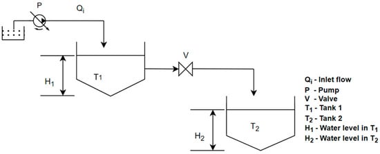
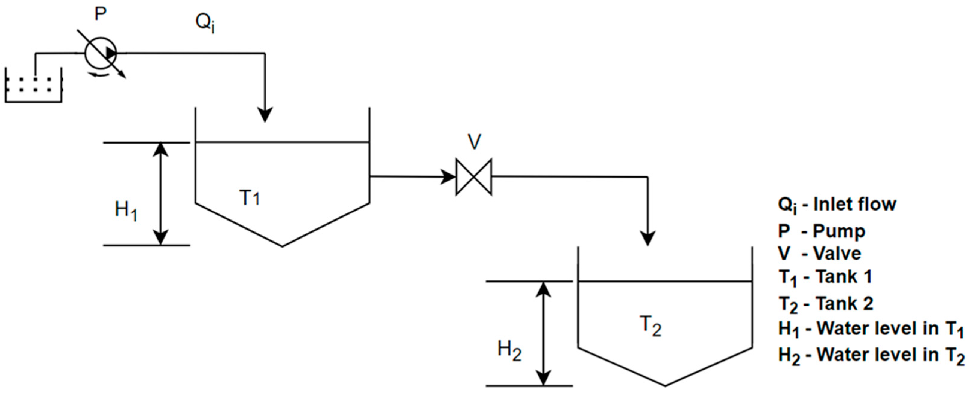
The system represents a pressurized water pipeline between two storage tanks within a wastewater treatment plant. The upstream tank T1 serves as the supply reservoir, while the downstream tank T2 functions as the receiving unit. The difference in water surface elevation between the two tanks (H1–H2) establishes the static head of the system. The water is conveyed through the pipeline by means of a pump P, which compensates for additional losses to maintain the required flow. The pipeline includes a valve V for flow regulation.
The section of WWTP that will be modeled is illustrated in Figure 2.
Figure 2.
The concept of the modeling process.
3.2. Governing Equations
The flow in the system is governed by steady-state incompressible fluid mechanics laws.
Each pipe is modeled using the continuity equation and the momentum/energy equation (head loss, pump head, and elevation changes), while junctions enforce flow distribution and pressure equilibrium.
The continuity equation is applied at every junction j, ensuring conservation of mass throughout the network:
where Qin,j is the flow entering a certain junction j and Qout,j is the flow leaving the junction j.
The Bernoulli equation is applied for every pipe segment between two connected nodes i (upstream) and j (downstream), ensuring that energy is conserved:
where Hi is the total head at the upstream section, Hp is the head added by a pump, Hj is the head at the downstream section, and hl is the total energy losses in the pipe segment from section i to section j.
The model assumes fully filled conduits, uniform velocity across each pipe cross-section, and uses empirical head loss formulations to describe friction effects. The total head loss in the pipe segment is calculated as a sum of the friction losses and minor losses in the pipe segment between the two sections.
The friction losses occur as the fluid flows through a pipe because of friction between the moving fluid and the internal pipe wall, as well as internal friction within the fluid itself. The friction losses hf are calculated by the Darcy–Weisbach equation:
where f is the friction factor, L is the pipe segment length, D is the pipe diameter, and v is the average fluid velocity in the pipe cross-section.
Minor losses occur in a piping system due to disturbances in the flow caused by fittings, transitions, and devices such as bends, valves, tees, reducers, expansions, inlets, outlets, and others, which create turbulence or flow separation. The minor losses hm are calculated by the equation:
where ∑ξ is the sum of the fitting’s loss coefficients.
Device behavior is captured by a pump head curve (Q) and a valve loss relation represented by the valve loss coefficient (Q).
The outlined equations serve as the basis for future numerical simulations.
The hydraulics models that are going to be developed in the future are going to address several core engineering problems, fundamental to the WWTP operation and its transport system. The core objectives include accurate flow regulation, pressure drop control, and optimization of internal flow transport between the tanks, pipelines, pumps, and valves. All the mentioned parameters are essential because they offer stable water distribution between the objects, preventing system imbalance, maintaining safe operating conditions, avoiding cavitation in pumps, reducing the appearance of water hammer events, minimizing the water losses, etc.
3.3. Model Parameters and Objectives
The input parameters of the model will include:
- Geometric data: pipe length, pipe diameter, elevation of tanks and nodes;
- Hydraulic data: pipe roughness, fluid density, and fluid viscosity;
- Equipment characteristics: pump curve represented by coefficients, valve loss coefficient, fittings losses;
- Operating conditions: water discharge, tank water level, pressure above tanks.
The determination of the model input parameters is based directly on measured physical characteristics of the experimental system, laboratory documents, and best engineering practices. Pipe length, diameter, and wall thickness will be taken from laboratory specifications or direct measurements. Pipe roughness will be selected from standard values for the given material. The thermophysical properties of water will be determined based on diagrams for temperature dependence. One set of data on operating conditions, such as water flow rate and pressure, would be physically measured and intended for validating the model, while another set of data would be defined for further numerical analysis. Additional parameters such as minor loss coefficients, pump performance, and valve characteristics will be obtained from laboratory documentation or equipment datasheets.
The conceptual model provides the theoretical framework for analyzing the hydraulic behavior of the water network. It establishes relationships between flow, head, and losses that affect system performance.
The hydraulic model will be developed in some of the software mentioned above to simulate steady-state flow conditions, accounting for head losses due to pipe friction, as well as minor losses from valves, bends, and other fittings. As a result of the simulation, the variation in pressure and velocity throughout the system will be obtained under certain operating conditions to evaluate the hydraulic performance of the system.
3.4. Model Construction Process
The development of the modeling concept will link real engineering practice with numerical model implementation. This procedure will ensure that the hydraulic behavior of the laboratory WWTP equipment, which will consist of two interconnected tanks, a regulating valve, and a centrifugal pump, will be accurately represented while maintaining computational efficiency. System simplification, parameter acquisition, and parameter calibration will be the three key stages.
System simplification: This step involves translating the physical hydraulic setup into a simplified mathematical model. The system’s essential hydraulic components will be:
- Tank 1 and Tank 2 are going to be modeled as variable-level control volumes with inflow–outflow relationships controlled by continuity.
- Pump is going to be represented by using head–flow (H–Q) performance curves.
- Valve is going to be simplified as a hydraulic resistance with a characteristic flow coefficient (Cv or discharge coefficient).
- Connecting pipelines are going to be represented as one-dimensional elements governed by the energy equation, including friction losses and local/linear losses.
This will allow the model to reproduce important hydraulic behavior such as flow distribution, pressure drop, pump performance, and water-level evolution while avoiding unnecessary geometric modeling or CFD-level complexity.
Parameter acquisition: When the system structure is defined, the next step will be collecting the physical and operational parameters required for hydraulic computation. These parameters can be grouped into four categories:
- Geometric parameters: Tank cross-sectional area and volume–height relationship, pipe length, diameter, roughness, valve type, and opening characteristics.
- Hydraulic resistance parameters: Darcy–Weisbach friction factor or Hazen–Williams coefficient, local loss coefficients (elbow, t-piece, contraction/expansion), valve discharge coefficient (Cd), or flow coefficient (Cv).
- Pump performance parameters: Manufacturer H–Q curve, best efficiency point (BEP), power, and rotational speed.
- Water loss and leakage parameters: Small leak flows through joints, fittings, or intentional orifices. Evaporation (if relevant).
These parameters will be obtained from laboratory measurements, manufacturer data, or standard hydraulic correlations. Accurate parameter acquisition will be essential because these values directly influence the capabilities of the simulation.
Parameter calibration: The final step is parameter calibration. In this step, model parameters are going to be adjusted to ensure a good relationship between simulated results and measurements collected from the laboratory equipment. Calibration will focus on core hydraulic parameters. The ones that significantly influence system behavior are:
- Flow-related parameters: Pump head–flow curve adjustment (curve-fitting), valve Cd/Cv coefficient tuning based on measured flows, leak-loss coefficient tuning, etc.
- Pressure drop parameters: Calibration of friction factor to match measured head loss, adjustment of minor-loss coefficients (K-values).
- Head–flow dependence: Fitting pump H–Q curves to ensure realistic response under different valve openings, adjusting pipeline resistance to match flow–head relationships.
- Tank dynamics: Validation of tank level change rates, adjusting effective cross-sectional area if geometry introduces nonlinearities.
Parameter calibration is going to be carried out by using iterative simulation–measurement comparison in the software MATLAB/Simulink R2021a, AFT, or the programming language Python 3.8.10. Performance indicators such as RMSE and R2 are going to be used to quantify the fitting quality. This systematic tuning process ensures that the final model accurately reflects real hydraulic behavior under different operational scenarios, including start-up of the pump, valve adjustments, and water transfer between tanks.
4. Conclusions
Modeling hydraulic parameters is crucial in the design and operation of a wastewater treatment plant. Having a simulation can help by ensuring reliable flow distribution, system efficiency, and addressing some operational risks, etc. Most of the available and reviewed papers are dedicated to modeling physical, chemical, and biological parameters in WWTPs, while very few deal with modeling hydraulic parameters. Also, the newest papers in this field are mostly about using ANN/ML for predicting the efficiency of WWTP or predicting the quality of the effluent. This paper is focused on developing a concept for the modeling of the hydraulic parameters in WWTP, such as flow, pressure drop, the dependence between head and flow, and water losses. In this paper, the concept of WWTP is represented, as well as the modeling and simulation of it.
4.1. Basis for Software Selection
Available software according to the reviewed literature, and further, that will be used is MATLAB/Simulink, AFT, and the Python programming language. Other software is CFD, EPANET, PipeFlow Expert, but in further research, they will not be used for modeling and simulation. Also, control strategies will not be part of this paper since they will be a topic for future research.
MATLAB/Simulink is mostly used software for WWTP dynamic modeling. It supports the development of electro-mechanical, data-driven, and hybrid models. Usually, it has been used for simulating activated sludge processes, clarifier dynamics, aeration control, and hydrologic runoff behavior. The result from the simulation provides a flexible environment for differential equation modeling, control design, and real-time simulation. AFT software tools, including AFT Fathom, Arrow, and Impulse, were selected because of their capabilities in modeling hydraulic networks, pumps and valves, compressible/incompressible flow, and transient events. According to the references, AFT has been successfully applied to sludge transport, aeration air systems, digester recirculation loops, gas piping networks, and surge analysis. As an open-source programming language, Python is used for numerical modeling, optimization, ML, and data analysis in environmental engineering. The literature represents its implementation in developing AI/ML models for WWTP performance prediction, including ANN, LSTM, RF, SVM, ARIMA, and PINN-based approaches. NumPy, SciPy, TensorFlow, PyTorch, and Pandas, as Python’s scientific libraries, will enable flexible implementation of conventional and intelligent modeling approaches.
CFD, EPANET, and PipeFlow Expert were selected as supporting tools because of their capabilities for hydraulic and process modeling. CFD solvers—primarily ANSYS Fluent and CFX—offers high-resolution 2D/3D analysis of flow patterns, turbulence, mixing, settling behavior, and multiphase interactions in WWTP units. It is usually used for modeling aeration basins, clarifiers, digesters, and oxidation ditches. EPANET is used for modeling pressurized distribution networks and reclaimed water systems. It enables simulation of flow, pressure, water age, and disinfectant decay. According to the literature, it has been effectively applied to greywater reuse and effluent reuse systems. PipeFlow Expert provides a modeling and simulation environment for steady-state pipeline analysis, pump sizing, energy calculations, and friction loss evaluation. Mostly, it is suitable for preliminary hydraulic design of WWTP auxiliary pipelines and closed-loop process networks. Together, these software tools support detailed hydraulic characterization from component-level CFD insights to system-level pipeline simulations.
4.2. Recommendation for Future Work
Modeling and simulation of the proposed hydraulic parameters are going to be possible by using the mentioned software, such as MATLAB/Simulink, Python, and AFT. The results from the simulation will be compared with the results from the measurements that will be made with the didactic equipment for WWTP that will be installed in the Laboratory of Automation at the Faculty of Mechanical Engineering, Department of Hydraulic Engineering and Automation, to validate the model and verify the experimental results. In order to capture the impact of different operating conditions, numerical simulations will be performed for flow regimes outside the measurement points.
Because of the needs of Macedonia to align with the European Union (EU), in recent years of the country’s development, the need for WWTP construction in every big and small city or village is extremely important. Therefore, the results from both simulations and laboratory measurements will serve as a foundation for analyzing different operational scenarios and proposing optimal and efficient process configurations for real facilities.
Therefore, future steps will be installing the equipment in the laboratory, making models, simulations, measurements, and results analysis. Furthermore, different control techniques could be implemented and analyzed on a didactic plant that should be replicated in real plants. Creating a Digital Twin of WWTP is another future step that should be taken using the existing laboratory equipment and the software or programming language mentioned.
Author Contributions
Conceptualization, R.K. and M.L.; Investigation, R.K. and M.L.; Writing—Original Draft Preparation, R.K. and M.L.; Writing—Review and Editing, R.K., M.L., Z.M., E.Z. and D.B.; Supervision, Z.M., E.Z. and D.B.; Project Administration, Z.M. All authors have read and agreed to the published version of the manuscript.
Funding
This research was funded by the Ministry of Education and Science of the Republic of Macedonia, grant number 15-6171/30 signed on 7 August 2025. The funders had no role in the design of the study; in the collection, analyses, or interpretation of data; in the writing of the manuscript; or in the decision to publish the results.
Data Availability Statement
The original contributions presented in this study are included in the article. Further inquiries can be directed to the corresponding author.
Acknowledgments
This paper is written under the project title Digital Modeling and Control of a Wastewater Treatment Plant, which is supported by the Ministry of Education and Science of the Republic of Macedonia under the grant agreement number 15-6171/30 signed on 7 August 2025. The authors have reviewed and edited the output and take full responsibility for the content of this publication.
Conflicts of Interest
The authors declare no conflicts of interest.
Abbreviations
The following abbreviations are used in this manuscript:
| WWTP | Wastewater Treatment Plant |
| CFD | Computational Fluid Dynamics |
| COD | Chemical Oxygen Demand |
| ADM | Anaerobic Digestion Model |
| MRF | Multiple Reference Frame |
| ANN | Artificial Neural Network |
| ML | Machine Learning |
| ANFIS | Adaptive Neuro-Fuzzy Interface System |
| FFNN | Feed-Forward Neural Network |
| SVM | Support Vector Machines |
| MLR | Multiple Linear Regression |
| BOD | Biological Oxygen Demand |
| TN | Total Nitrogen |
| RNN | Recurrent Neural Network |
| LSTM | Long Short-Term Memory |
| ARIMA | AutoRegressive Integrated Moving Average |
| RF | Random Forest |
| GIS | Geographic Information Systems |
| WRRF | Wastewater Resource Recovery Facilities |
| THS | Thermally Hydrolyzed Sludge |
| MLP | Multilayer Perceptron |
| DO | Dissolved Oxygen |
| PINN | Physical-Informed Neural Network |
| T | Temperature |
| NO3− | Nitrate |
| NH4+ | Ammonium |
References
- UNESCO. The United Nations World Water Development Report 2021: Valuing Water; UNESCO: Paris, France, 2021. [Google Scholar]
- Tchobanoglous, G.; Stensel, H.; Tsuchihashi, R.; Burton, F. Wastewater Engineering: Treatment and Resource Recovery, 5th ed.; McGraw Hill: New York, NY, USA, 2014. [Google Scholar]
- Hreiz, R.; Latifi, M.A.; Roche, N. Optimal design and operation of activated sludge processes: State-of-the-art. Chem. Eng. J. 2015, 281, 900–920. [Google Scholar] [CrossRef] [Scilit]
- Muga, H.E.; Mihelcic, J.R. Sustainability of wastewater treatment technologies. J. Environ. Manag. 2008, 88, 437–447. [Google Scholar] [CrossRef] [Scilit]
- Rivas, A.; Irizar, I.; Ayesa, E. Model-based optimisation of Wastewater Treatment Plants design. Environ. Model. Softw. 2008, 23, 435–450. [Google Scholar] [CrossRef] [Scilit]
- Duarte, M.S.; Martins, G.; Oliveira, P.; Fernandes, B.; Ferreira, E.C.; Alves, M.M.; Lopes, F.; Pereira, M.A.; Novais, P. A Review of Computational Modeling in Wastewater Treatment Processes. ACS EST Water 2024, 4, 784–804. [Google Scholar] [CrossRef] [Scilit] [PubMed]
- Umarov, U.; Arifjanov, A.; Rizayev, A.; Umarova, D. Mathematical modeling of wastewater treatment facilities of transport enterprises. E3S Web Conf. 2023, 401, 03031. [Google Scholar] [CrossRef] [Scilit]
- Biliaiev, M.M.; Kozachyna, V.A.; Kyrychenko, M.V.; Skuratov, M.O.; Chirkov, A.O.; Filonenko, H.K. Mathematical models for water treatment problems. Sci. Transp. Prog. 2025, 109, 5–13. [Google Scholar] [CrossRef] [Scilit]
- Eshbobaev, J.A.; Khamidov, B.T.; Norkobilov, A.T.; Kodirov, O.S. Development of the computer model of the waste water treatment process using ion-exchange resins in the matlab program. Chem. Technol. Control. Manag. 2023, 2023, 63–69. [Google Scholar] [CrossRef] [Scilit]
- Hodasz, N.I.; Bradila, V.I.; Nascu, I.; Lendek, Z. Modeling and parameter estimation for an activated sludge wastewater treatment process. In Proceedings of the 2016 IEEE International Conference on Automation, Quality and Testing, Robotics (AQTR), Cluj-Napoca, Romania, 19–21 May 2016; IEEE: New York, NY, USA, 2016; pp. 1–6. [Google Scholar] [CrossRef] [Scilit]
- Ersahin, M.E. Modeling the dynamic performance of full-scale anaerobic primary sludge digester using Anaerobic Digestion Model No. 1 (ADM1). Bioprocess Biosyst. Eng. 2018, 41, 1539–1545. [Google Scholar] [CrossRef] [Scilit]
- Hwangbo, S.; Al, R.; Sin, G. An integrated framework for plant data-driven process modeling using deep-learning with Monte-Carlo simulations. Comput. Chem. Eng. 2020, 143, 107071. [Google Scholar] [CrossRef] [Scilit]
- Bello, O.; Hamam, Y.; Karim, D. Non-linear modelling and identification of a coagulant dosage system for water treatment plants. In Proceedings of the 2014 IEEE International Conference on Industrial Technology (ICIT), Busan, Republic of Korea, 26 February–1 March 2014; IEEE: New York, NY, USA, 2014; pp. 11–17. [Google Scholar] [CrossRef] [Scilit]
- Bello, O.; Hamam, Y.; Djouani, K. Modelling and validation of a coagulation chemical dosing unit for water treatment plants. In Proceedings of the 2014 IEEE Conference on Control Applications (CCA), Antibes/Nice, France, 8–10 October 2014; IEEE: New York, NY, USA, 2014; pp. 765–771. [Google Scholar] [CrossRef] [Scilit]
- Haghiri, S.; Moharramzadeh, S.; Daghighi, A. Optimum Coagulant Forecasting with Modeling the Jar Test Experiments Using ANN. Drink. Water Eng. Sci. 2018, 11, 1–8. [Google Scholar] [CrossRef] [Scilit]
- Kuriqi, A. Simulink Application on Dynamic Modeling of Biological Waste Water Treatment for Aerator Tank Case. Int. J. Sci. Technol. Res. 2014, 3, 69–72. Available online: https://www.ijstr.org/ (accessed on 8 August 2025).
- Sardarova, S.A.I.; Azizov, A.G.H. Control model of the wastewater treatment process. PAHTEI-Proc. Azerbaijan High Tech. Educ. Inst. 2024, 36, 34–41. [Google Scholar] [CrossRef] [Scilit]
- Dordescu, M.; Nicolescu, F. Modelling the active sludge treatment process in recirculation basins using the Simulink environment. IOP Conf. Ser. Earth Environ. Sci. 2021, 664, 012046. [Google Scholar] [CrossRef] [Scilit]
- Alex, J.; To, T.B.; Hartwig, P. Improved design and optimization of aeration control for WWTPs by dynamic simulation. Water Sci. Technol. 2002, 45, 365–372. [Google Scholar] [CrossRef] [Scilit]
- Nemcik, J.; Krupa, F.; Ozana, S.; Slanina, Z. Wastewater Treatment Modeling Methods Review. IFAC-PapersOnLine 2022, 55, 195–200. [Google Scholar] [CrossRef] [Scilit]
- Serdarevic, A.; Dzubur, A. Wastewater process modeling. Coupled Syst. Mech. 2016, 5, 21–39. [Google Scholar] [CrossRef] [Scilit]
- Bowen, J.; Perry, D.; Bell, C. Hydrologic and Water Quality Model Development Using Simulink. J. Mar. Sci. Eng. 2014, 2, 616–632. [Google Scholar] [CrossRef] [Scilit]
- Song, J.-H.; Her, Y.; Park, J.; Lee, K.-D.; Kang, M.-S. Simulink Implementation of a Hydrologic Model: A Tank Model Case Study. Water 2017, 9, 639. [Google Scholar] [CrossRef] [Scilit]
- Worm, G.I.M.; Mesman, G.A.M.; Van Schagen, K.M.; Borger, K.J.; Rietveld, L.C. Hydraulic Modelling of Drinking Water Treatment Plant Operations. Drink Water Eng. Sci. 2009, 1, 15–20. [Google Scholar] [CrossRef] [Scilit]
- Małoszewski, P.; Wachniew, P.; Czupryński, P. Hydraulic Characteristics of a Wastewater Treatment Pond Evaluated through Tracer Test and Multi-Flow Mathematical Approach. Pol. J. Environ. Stud. 2006, 15, 105–110. [Google Scholar]
- PipeFlow—Fluid Thinking Software Solution. Available online: https://www.pipeflow.com/pipe-flow-expert-software (accessed on 1 September 2025).
- EPA, Water Research. Available online: https://www.epa.gov/water-research (accessed on 25 August 2025).
- Chowdhury, R.K.; Rajput, M.A. Will greywater reuse really affect the sewer flow? Experience of a residential complex in Al Ain, UAE. Water Supply 2017, 17, 246–258. [Google Scholar] [CrossRef] [Scilit]
- Killion, S.M. Design and Modeling of Infrastructure for Residential and Community Water Reuse. Master’s Thesis, University of Nebraska, Lincoln, NE, USA, 2011. [Google Scholar]
- Stillwell, A.S.; Twomey, K.M.; Osborne, R.; Greene, D.M.; Pedersen, D.W.; Webber, M.E. An integrated energy, carbon, water, and economic analysis of reclaimed water use in urban settings: A case study of Austin, Texas. J. Water Reuse Desalination 2011, 1, 208–223. [Google Scholar] [CrossRef] [Scilit]
- Jia, H.; Wei, W.; Xin, K. Hydraulic model for multi-sources reclaimed water pipe network based on EPANET and its applications in Beijing, China. Front. Environ. Sci. Eng. China 2008, 2, 57–62. [Google Scholar] [CrossRef] [Scilit]
- Costa, J.; Mesquita, E.; Ferreira, F.; Figueiredo, D.; Rosa, M.J.; Viegas, R.M.C. Modeling Chlorine Decay in Reclaimed Water Distribution Systems—A Lisbon Area Case Study. Sustainability 2023, 15, 16211. [Google Scholar] [CrossRef] [Scilit]
- Ramirão Costa, J.M.S. Modelling Chlorine Decay in Reclaimed Water Distribution Systems. Ph.D. Thesis, University of Lisbon, Lisbon, Portugal, 2023. [Google Scholar]
- Limbong, B.; Suripin, S.; Sudarnoutaomo, S. EPANET Model Clean Water Network Calibration using Modified Roughness C Number Hazen William Method. J. Pensil Pendidik. Tek. Sipil 2022, 11, 171–185. [Google Scholar] [CrossRef] [Scilit]
- Shiu, C.C.; Chung, C.C.; Chiang, T. Enhancing the EPANET Hydraulic Model through Genetic Algorithm Optimization of Pipe Roughness Coefficients. Water Resour. Manag. 2024, 38, 323–341. [Google Scholar] [CrossRef] [Scilit]
- AFT—Fathom 14. Available online: https://www.aft.com/products/fathom (accessed on 26 August 2025).
- Robillard, D. Simulation of Transfer and Distribution of Thermally Hydrolyzed Sludge with AFT Fathom. Available online: https://www.aft.com/images/casestudies/Water_F_CH2MHill_2018.pdf (accessed on 26 August 2025).
- Knight, T. Digester Complex Heat Reservoir Recirculation System Hydraulic and Thermal Analysis Accomplished with AFT Fathom. Available online: https://www.aft.com (accessed on 26 August 2025).
- Garikipati, S. Water Reclamation System Modeling with AFT Fathom. Available online: https://www.aft.com (accessed on 25 August 2025).
- Arthur, M. AFT Fathom™ Integral to Resolving Stormwater Flooding Issues, Provides Alternatives $25MM Under Competitor Scope. Available online: https://www.aft.com (accessed on 25 August 2025).
- Onat, E.; Walters, T.; Mobley, D.M.; Mead, J.J. Hydraulic Model Calibration of a Nuclear Plant Service Water System. In Proceedings of the ASME 2016 Power and Energy Conference, Charlotte, North Carolina, 26–30 June 2016. [Google Scholar]
- AFT Arrow. Available online: https://www.aft.com/products/arrow (accessed on 25 August 2025).
- AFT in the Water & Wastewater Industry. Available online: https://www.aft.com/industries/water-wastewater (accessed on 22 December 2025).
- Deal, M. Wastewater Treatment Plant Resolves Downtime Issue and Saves Up to $600,000 with AFT Arrow. Available online: https://www.aft.com (accessed on 22 December 2025).
- Steiner, M.; Murphy, J. How Optimized Aeration Systems Can Save Millions at Treatment Plants. Available online: https://www.parametrix.com/how-optimized-aeration-systems-can-save-millions-at-treatment-plants/ (accessed on 26 August 2025).
- Knight, T. Digester Gas Unit Expansion Modeled with AFT Arrow Confirms Pressure and Flow Capacity. Available online: www.aft.com (accessed on 27 August 2025).
- KC Water. Blue River Wastewater Treatment Plant Biosolids Facility. January 2020. Available online: https://www.blueriverbiosolids.com/wp-content/uploads/2020/04/BRBF_Final_BODR_20200124.pdf (accessed on 27 August 2025).
- AFT Impulse. Available online: https://www.aft.com/products/impulse (accessed on 27 August 2025).
- Lira, C. AFT Impulse Helps Desalinization Plant Reduce Shutdowns and Save $175,000 Annually. Available online: https://www.aft.com/images/casestudies/Water_I_Procure.pdf (accessed on 27 August 2025).
- Janus, T.; Burt, D.; Taylor, A.; Glancy, V. Application of CFD and dynamic process simulation for retrofitting of a 800,000 PE trickling filter WWTP. In Proceedings of the 1st European Water and Wastewater Management Conference, Newcastle, UK, 2007; Available online: https://conferences.aquaenviro.co.uk/proceedings/application-of-cfd-and-dynamic-process-simulation-for-retrofitting-of-a-800000-pe-trickling-filter-wwtp/ (accessed on 27 August 2025).
- Dairi, S.; Khoualdia, W.; Mrad, D.; Bouamrane, A.; Djebbar, Y.; Abida, H. Improving secondary settling tanks performance by applying CFD models for design and operation. Water Supply 2023, 23, 2313–2331. [Google Scholar] [CrossRef] [Scilit]
- Xu, Q.; Luo, X.; Xu, C.; Wan, Y.; Xiong, G.; Chen, H.; Zhou, Q.; Yan, D.; Li, X.; Li, Y.; et al. The Whole Process CFD Numerical Simulation of Flow Field and Suspended Solids Distribution in a Full-Scale High-Rate Clarifier. Sustainability 2022, 14, 10624. [Google Scholar] [CrossRef] [Scilit]
- Yu, L.; Ma, J.; Chen, S. Numerical simulation of mechanical mixing in high solid anaerobic digester. Bioresour. Technol. 2011, 102, 1012–1018. [Google Scholar] [CrossRef] [Scilit] [PubMed]
- Arnau, R.; Climent, J.; Martínez-Cuenca, R.; Rodríguez, J.; Chiva, S. Evaluation of hydraulic mixing performance in a full-scale anaerobic digester with an external liquid recirculation system using CFD and experimental validation. Chem. Eng. Sci. 2022, 251, 117392. [Google Scholar] [CrossRef] [Scilit]
- Wu, B. CFD simulation of mixing for high-solids anaerobic digestion. Biotechnol. Bioeng. 2012, 109, 2116–2126. [Google Scholar] [CrossRef] [Scilit] [PubMed]
- Karpinska, A.M.; Bridgeman, J. CFD as a Tool to Optimize Aeration Tank Design and Operation. J. Environ. Eng. 2018, 144, 05017008. [Google Scholar] [CrossRef] [Scilit]
- Mamedov, T. CFD Simulation of Aeration and Mixing Processes in a Full-Scale Oxidation Ditch. Master’s Thesis, Politecnico Di Milano, Milano, Italy, 2019. [Google Scholar]
- Bekrentchir, K.; Mahdi, K.; Debab, A.; Khelladi, M. Numerical Investigation of Hydrodynamic in a Full-Scale Surface Aeration Tank. Int. J. Heat Technol. 2022, 40, 927–938. [Google Scholar] [CrossRef] [Scilit]
- Alvarado-Rodriguez, C.E.; Sigalotti LDi, G.; Klapp, J.; Fierro-Santillan, C.R.; Aragon, F.; Uribe-Ramirez, A.R. SPH simulations of turbulent flow in curved pipes with different geometries. A comparison with experiments. J. Fluids Eng. 2021, 143, 091503. [Google Scholar] [CrossRef] [Scilit]
- Jia, L.; Zeng, Y.; Liu, X.; Peng, C.; Li, D.; Liu, F.; He, L. Numerical Simulation and Experimental Verification of the Velocity Field in Asymmetric Circular Bends. Sci. Rep. 2024, 14, 13933. [Google Scholar] [CrossRef] [Scilit]
- Alihosseini, M.; Ackl, R.A.; Thamsen, P.U. CFD Modelling and Experimental Investigation of Flow Behaviour in Sewer Pipes. In Proceedings of the Conference on Modelling Fluid Flow (CMFF’18), Budapest, Hungary, 4–7 September 2018. [Google Scholar]
- Wiens, T. Correction Factors for the Use of 1D Solution Methods for Dynamic Laminar Liquid Flow through Curved Tubes. Fluids 2024, 9, 138. [Google Scholar] [CrossRef] [Scilit]
- Kesler, T. Comparing 1D, 2D, and 3D Hydraulic Models in Urban Flooding Applications. Master’s Thesis, Utah State University, Logan, UT, USA, 2023. Available online: https://digitalcommons.usu.edu/etd/8691 (accessed on 28 August 2025).
- Banaei, F.K. Dynamic Performance Analysis and Simulation of a Full Scale Activated Sludge System Treating an Industrial Wastewater Using Artificial Neural Network. Int. J. Eng. 2013, 26, 465–472. [Google Scholar] [CrossRef] [Scilit]
- Nourani, V.; Elkiran, G.; Abba, S.I. Wastewater treatment plant performance analysis using artificial intelligence—An ensemble approach. Water Sci. Technol. 2018, 78, 2064–2076. [Google Scholar] [CrossRef] [Scilit] [PubMed]
- Wongburi, P.; Park, J.K. Prediction of Wastewater Treatment Plant Effluent Water Quality Using Recurrent Neural Network (RNN) Models. Water 2023, 15, 3325. [Google Scholar] [CrossRef] [Scilit]
- Al-Asheh, S.; Mjalli, F.S.; Alfadala, H.E. Forecasting Influent-Effluent Wastewater Treatment Plant Using Time Series Analysis and Artificial Neural Network Techniques. Chem. Prod. Process Model. 2007, 2. [Google Scholar] [CrossRef] [Scilit]
- Fuck, J.V.R.; Cechinel, M.A.P.; Neves, J.; de Andrade, R.C.; Tristão, R.; Spogis, N.; Riella, H.G.; Soares, C.; Padoin, N. Predicting effluent quality parameters for wastewater treatment plant: A machine learning-based methodology. Chemosphere 2024, 352, 141472. [Google Scholar] [CrossRef] [Scilit] [PubMed]
- Koksal, E.S.; Aydin, E. A Hybrid Approach of Transfer Learning and Physics-Informed Modeling: Improving Dissolved Oxygen Concentration Prediction in an Industrial Wastewater Treatment Plant. Chem. Eng. Sci. 2024, 304, 121088. [Google Scholar] [CrossRef] [Scilit]
- Mexis, K.; Xenios, S.; Trokanas, N.; Kokossis, A. A Physics-Informed Approach to Dynamic Modeling and Parameter Estimation in Biotechnology. In Proceedings of the 35th European Symposium on Computer Aided Process Engineering, Ghent, Belgium, 6–9 July 2025; pp. 1750–1755. [Google Scholar] [CrossRef] [Scilit]

Disclaimer/Publisher’s Note: The statements, opinions and data contained in all publications are solely those of the individual author(s) and contributor(s) and not of MDPI and/or the editor(s). MDPI and/or the editor(s) disclaim responsibility for any injury to people or property resulting from any ideas, methods, instructions or products referred to in the content. |
© 2026 by the authors. Licensee MDPI, Basel, Switzerland. This article is an open access article distributed under the terms and conditions of the Creative Commons Attribution (CC BY) license.