


Abstract
This study proposes a systematic decision-making framework for optimizing the location and construction timing of dynamic interference sediment reduction measures in heavily silted harbor basins. The methodology integrates hydrodynamic modeling, sediment transport analysis, and construction process optimization to minimize engineering costs while maximizing the efficiency of sediment reduction. The core principle involves leveraging hydrodynamic and sediment transport dynamics to identify critical intervention points (location) and favorable construction windows (timing). Taking the southern harbor basin of Jiangsu Yancheng Binhai Port as a case study, the Lagrangian particle tracking method is used to analyze particle transport pathways in different areas during various tidal phases. The results show that in the southern part of the harbor basin, disturbed suspended sediment can be effectively transported out of the basin during most of the tidal cycle, with only about 3.34 h per tidal cycle being unsuitable for operations; thus, this area is identified as the optimal operation location. In contrast, the central area is dominated by a vortex that prevents sediment from being flushed out within a short time, making it unsuitable for sediment reduction operations. Although the northern area cannot fully export sediment within a single tidal cycle, it can rapidly convey sediment to the southern area, where sediment can be removed through relay operations over multiple tidal cycles. This study provides a quantitative method for determining optimal operation locations and construction timing for dynamic interference sediment reduction technology in heavily silted ports.
1. Introduction
The construction of harbor breakwaters and other structures alters the local flow field structure in the vicinity of the harbor basin. When the alignment of the breakwater forms a large angle with the predominant current direction in the adjacent waters, the flow velocity inside the harbor basin is reduced due to the sheltering effect of the breakwater. In areas with fine-grained seabed sediments, this often leads to siltation problems inside the harbor basin, as observed in Chinese ports like Huanghua Port, Zhuhai Port, and Lianyungang Port. To ensure the navigational safety of harbor basins and channels, dredging is required to remove accumulated sediment. Dredging methods can be primarily categorized into mechanical dredging, hydraulic dredging, and jet or pneumatic disturbance dredging [1,2,3,4].
Mechanical dredging, which relies on dredgers for excavation, is the primary method for maintaining large ports and navigation channels. For instance, the Deepwater Channel of the Yangtze River Estuary requires the annual removal of tens of millions of cubic meters of sediment by dredgers [5]. Hydraulic dredging enhances hydrodynamic conditions by regulating water discharge and is mainly applied in approach channels below sluices and estuarine areas [6,7].
Pneumatic or submerged jet dredging utilizes high-pressure airflow or water jets to disturb bottom sediment, increase local flow turbulence, and thereby enhance the local flow’s sediment-carrying capacity. This suspends the sediment, allowing it to be transported away from the area by the current. This technology has been successfully applied to manage siltation below the tidal barrage of the Xinyi River Estuary Hub [8]. While this method is commonly used in high-dam reservoirs and urban rivers, its application in port navigation channels is relatively limited [6]. More recently, Mikac et al. [9] demonstrated that a jet pump-based ejectors plant effectively reduced sediment mud content and restored benthic diversity, offering an eco-friendly alternative to conventional dredging. These studies collectively support the hydrodynamic disturbance principle underlying the dynamic interference approach adopted in the present study.
High-velocity water jetting, also known as water injection dredging (WID), is an effective hydrodynamic dredging technique. As early as 1987, the Netherlands constructed the first purpose-built jet dredging vessel, Jetsed [10]. Jet dredgers operate by pumping water and ejecting it through nozzles to generate high-velocity jets (or injecting large volumes of water under low pressure) that impact and fluidize sediment deposits. The suspended sediment is then transported away by natural tidal or river currents, achieving the dredging purpose [11,12,13]. Since then, WID has been used worldwide for maintaining breakwaters, locks, and harbor basins. In recent years, many researchers have conducted various optimizations to improve the dredging efficiency of jet dredging machinery [14,15,16,17,18]. Furthermore, studies on the far-field impacts of WID and sediment resuspension under mechanical disturbance have provided deeper insights into sediment transport dynamics. These studies collectively support the theoretical basis of the dynamic interference approach employed in the present research.
The dynamic interference siltation reduction method (such as pneumatic or submerged water jetting) is a novel approach. Its core principle involves using high-pressure water flow to disturb bottom sediment, increasing local flow turbulence intensity, thereby enhancing the local flow’s sediment-carrying capacity to eliminate siltation. The sediment is suspended and transported away from the deposition area by the tide current [19]. Compared to the traditional “excavate and remove” approach of mechanical dredging, this method focuses more on “agitation and transport,” theoretically offering potential advantages like lower energy consumption and no need for spoil disposal. However, as the flow field inside the harbor basin is significantly influenced by the layout of structures such as breakwaters and entrance orientation, the effectiveness of dynamic interference operations varies greatly depending on the operation location and tidal phase. In heavily silted ports, dredging costs account for a high proportion of maintenance expenses, even significantly reducing corporate profits [19]. Therefore, optimizing operational strategies to improve siltation reduction efficiency and reduce costs is crucial.
Although the principle of dynamic interference technology is recognized, its practical application in complex harbor flow fields still faces challenges. The key lies in scientifically determining the optimal operation locations and corresponding operation timings, so that the disturbed and suspended sediment can be most effectively carried away by the tide currents. A method for determining maintenance dredging timing for the middle reaches of the Yangtze River waterway was proposed in 2024, incorporating multiple factors including water level processes, riverbed scour and deposition, and navigation conditions, thus providing a reference for related research [18].
The Lagrangian particle tracking method has been widely applied in estuarine transport studies [20,21] and proven effective for identifying optimal operation locations and timing for sediment reduction. Adopting this approach, the present study takes the heavily silted harbor basin of Jiangsu Binhai Port as the research object and aims to propose a systematic optimization framework for determining the optimal siting and construction timing of dynamic interference sediment reduction measures. This research integrates hydrodynamic modeling, sediment transport analysis, and construction process optimization. The core principle involves leveraging hydrodynamic and Lagrangian particle transport dynamics to identify critical intervention points (location) and favorable construction windows (timing), thereby minimizing engineering costs while maximizing siltation reduction efficiency.
The dynamic interference dredging equipment used in this study is an automatic dredging robot that can navigate underwater as required. It consists of two robots—one underwater and one at the sea surface—connected by a mud-water pipe. The underwater robot is responsible for suctioning sediment from the seabed, while the surface robot disperses the sediment into the water column. As this dredging robot has limited resistance to wind and waves, it cannot perform sediment dispersal operations under strong wind conditions. Therefore, when determining the operation time window for dynamic interference dredging in this study, we exclude periods with strong winds and large waves, and consider only the tidal operation windows under normal weather conditions.
2. Mathematical Model
2.1. Hydrodynamic Governing Equations
The Delft3D software (version 4.05.01) is used to construct the hydrodynamic model [22,23], and the Lagrangian particle tracking method is subsequently employed to simulate the transport pathways of sediment suspended by dynamic interference operations.
The model adopts a layered three-dimensional orthogonal curvilinear coordinate system. Through coordinate transformation, the irregular shoreline boundaries are converted into an orthogonal curvilinear framework, in which ξ = ξ(x,y) denotes the coordinate along the river channel direction, and η = η(x,y) denotes the coordinate perpendicular to the channel direction, and the σ is the vertical coordinate.
The layered three-dimensional hydrodynamic equations are as follows:
Depth-integrated continuity equation for the free-surface elevation equation:
Here, , are the coordinate conversion coefficients in the ξ and η directions, respectively; d is the still water depth; ζ is the water surface elevation. Q is Source/Sink term; U and V are the depth-averaged velocities in the ξ and η directions:
u and v represent the flow velocities in the ξ, η.
Momentum Equations:
ξ-direction:
η-direction:
In these equations, w represents the flow velocities in the σ directions; are the pressure gradient terms in the ξ and η directions; are the body force terms; are the momentum diffusion terms; f is the Coriolis parameter representing the effect of the Earth’s rotation; and is the density of water, is the vertical eddy viscosity coefficient.
k-ε turbulence model:
In these equations, Pk is the production term, Pkw is the production of turbulent kinetic energy due to waves, Bk is the buoyancy term, Pε is the production term, Pεw is the production of turbulent kinetic energy due to waves, c2ε is constant, and Bε is the buoyancy flux.
Eddy viscosity coefficient:
Vertical eddy viscosity coefficient is defined by:
2.2. Lagrangian Particle Tracking Method
After obtaining the tidal current field by solving with Delft3D-FLOW, a Lagrangian particle tracking model is established to track the trajectories of particles suspended by dynamic interference. The particles are marked so that their movement paths can be observed and it can be determined whether they are likely to be carried out of the harbor basin [24,25,26,27,28]. The spatial position of particles is determined by the following equation:
Here, denotes the spatial position of the i-th particle at the end of the k-th time step; represents the depth averaged velocity U and V at the spatial position , provided by the hydrodynamic model; Δt is the computational time step; denotes the additional displacement at the position due to diffusion.
2.3. Model Setup
Binhai Port in Yancheng, Jiangsu Province is a heavily silted port located near the Abandoned Yellow River Estuary—a region profoundly influenced by the historical sediment supply of the Yellow River. Since 1855, when the river shifted its course northward to enter the Bohai Sea in Shandong, the sediment supply to the abandoned delta was cut off, leading to continuous coastal erosion. Nevertheless, centuries of massive sediment discharge prior to the shift deposited a thick layer of fine clay across the seabed of the delta. This fine-grained sediment serves as the primary source material for subsequent harbor siltation.
Under the combined action of waves and currents, the subaqueous slope has been continuously eroded and deepened, with erosion intensity being greatest between depths of −2 and −10 m, especially around the −5 m depth zone. Consequently, the slope profile has progressively steepened and developed a concave shape. As erosion continues, its intensity gradually diminishes. Based on equilibrium profile predictions, the stable slope of the subaqueous foreshore is approximately 1:85, with the lower limit of equilibrium around −15 m. Seaward of the −15 m depth, the seabed becomes extremely flat, extending for tens of kilometers with gradients generally ranging from 1/300 to 1/2000. Despite the ongoing erosion, the widespread presence of fine clay in the area creates conditions highly conducive to sedimentation.
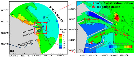
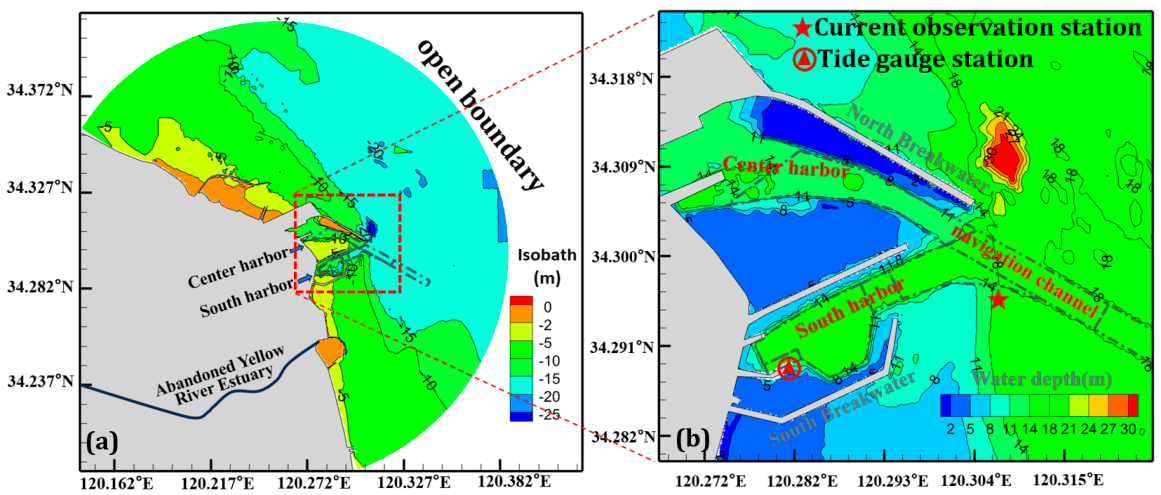
Given the favorable water depth and the socioeconomic demand for maritime transport, the Binhai Port Central Harbor Area and the South Harbor Basin were successively constructed near the Abandoned Yellow River Estuary (Figure 1a). The central harbor basin primarily handles dry bulk cargo (e.g., coal), liquid bulk cargo, and general cargo, while also accommodating container shipping. The southern harbor basin is dedicated to LNG operations. The layout features two harbor basins embraced by a pair of training jetties: the longer North Breakwater of the central basin and the shorter South Breakwater of the southern basin, as shown in Figure 1b.
Figure 1.
Binhai Port, Yancheng, Jiangsu Province, China. (a) The regional location of Binhai Port, the open boundary. (b) general layout of Binhai Port, water depth and tidal level and current observation stations.
Based on tidal gauge data from Binhai Port, Jiangsu, spanning 1963 to 1994, the statistics indicate that the average tidal range at Binhai Port is 1.76 m, with a maximum tidal range of 3.13 m. The flood tide duration is 4 h and 50 min, while the ebb tide duration is 7 h and 36 min.
A hydrodynamic model for Yancheng Port, Jiangsu, was established using the Delft3D model. The model employs a curvilinear coordinate grid, with the computational domain shown in Figure 1a. The grid spacing is 20 m × 20 m within the harbor basin, gradually coarsening to 100 m × 50 m toward the open boundaries, with 5 vertical layers. The open boundaries of the model are forced by the harmonic constants of nine major tidal constituents (M2, S2, N2, K2, K1, O1, P1, Q1, M4) from the astronomical tide [29]. The simulated flow fields during typical flood and ebb tides in the Binhai Port sea area obtained through numerical simulation are presented in Figure 2.
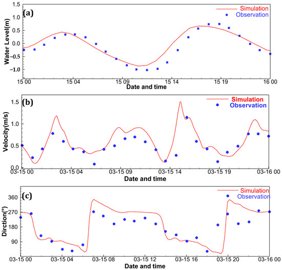
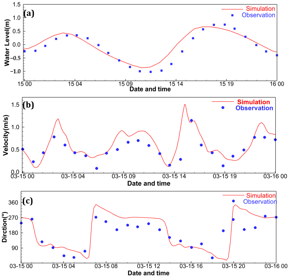
Figure 2.
Hydrodynamic validation of measured and simulated results at Binhai South harbor in March 2026. (a) Tidal level; (b) Depth-averaged flow velocity; (c) Depth-averaged flow direction.
2.4. Model Validation
Field measurements were conducted in 15 March 2026. Water level data were recorded at the wharf of the southern harbor basin, while tidal current velocities were measured simultaneously near the navigation channel at the entrance of Binhai Port. The spatial distribution of the observation points is shown in Figure 1b. Figure 2 compares the model predictions with field observations. The computed water levels and current directions capture the observed tidal rise and fall with good fidelity, and the high-water, low-water, and major phase features are generally well reproduced. These results demonstrate that the model adequately represents the hydrodynamic conditions in the Jiangsu Binhai Port basin and the surrounding coastal area.
3. Hydrodynamic and Sediment Siltation Characteristics of Heavily Silted Ports
3.1. Hydrodynamic Characteristics Analysis
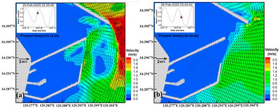
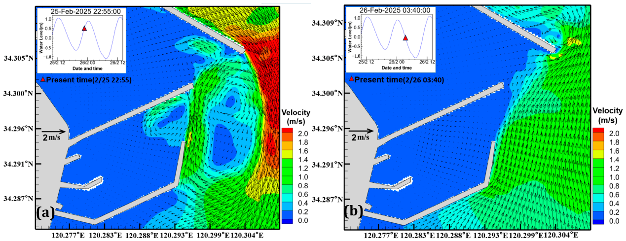
As shown in Figure 3a,b, during flood tide, the primary tidal current direction is from northwest to southeast. Due to the considerable length of the North Breakwater of the central basin, it exerts a strong flow-deflecting effect, generating a relatively large-scale vortex near the entrance of the dual-basin system. Simultaneously, because the South Breakwater of the southern basin turns toward the north-northeast direction at its entrance section and lies within the vortex induced by the flow deflection of the central basin’s North Breakwater, this unique layout results in the flow direction at the entrance of the southern basin being predominantly aligned with the South Breakwater toward the north-northeast for most of the flood tide duration.
Figure 3.
Typical tide flow field. (a) Flood tide flow field. (b) Ebb tide flow field. The inset panels denote the time series of tidal water level and the flow field.
At the entrance section of the southern harbor basin, the middle breakwater obstructs the north-northeast (NNE) directed flow, causing a portion of the water mass to enter the southern basin along the breakwater in the form of a counterclockwise vortex, thereby creating a flow diversion effect on the main current. As the water mass gradually moves into the relatively open waters in the central part of the basin, the flow velocity decreases progressively. The velocity in the western part of the harbor basin is very low, approximately 0.1 m/s, which is significantly lower than that outside the training jetties.
As shown in Figure 3b, during ebb tide, the primary tidal current direction is from southeast to northwest. The flow velocity inside the harbor basins remains very low, approximately 0.12 m/s, still much lower than the velocity outside the training jetties. Due to the flow-guiding effect of the South Breakwater of the southern basin, the flow direction at its entrance is predominantly aligned with the South Breakwater toward the north-northeast for most of the ebb tide duration.
Consequently, this unique embracing layout causes the flow direction at the entrance of the southern harbor basin to be predominantly north-northeast during most of the flood and ebb tide periods.
3.2. Substance Exchange in the Southern Harbor Basin
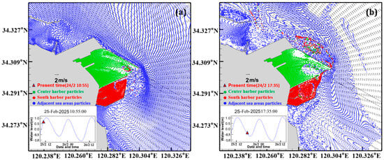
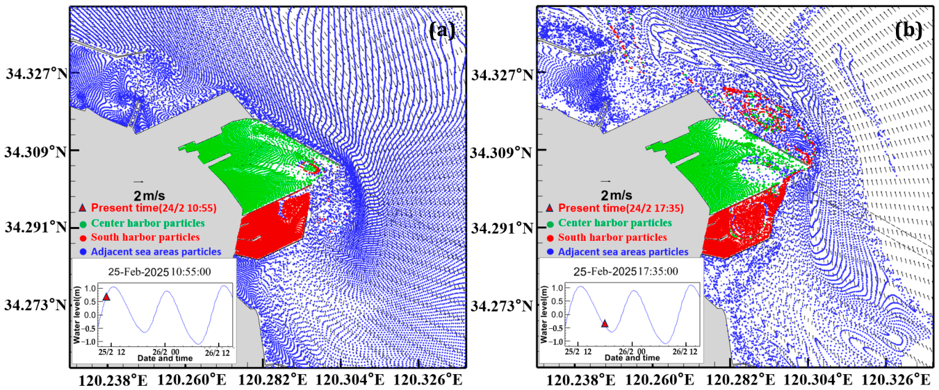
To characterize the substance exchange process between the inside and outside of the harbor basins, as well as the pathways for suspended sediment entering/exiting the basins and its transport routes within, green, red, and blue particles were deployed instantaneously in the central harbor basin, the southern harbor basin, and the area outside the basins, respectively. A Lagrangian particle tracking model was employed to trace the deployed particles. By analyzing the trajectories of the differently colored particles moving in and out of the basins, the substance exchange and its transport pathways within the harbor basins were examined. The results are shown in Figure 4.
Figure 4.
Substance exchange between inside and outside the harbor basin with particle tracking method. (a) Initially deployed particles. (b) Particle distribution at Typical time.
It can be observed that the hydrodynamic conditions within the harbor basins are weak, leading to slow substance exchange. In the southern harbor basin, the primary pathway for substance exchange is characterized by inflow from the north and outflow from the south. Particles entering the southern basin from the north are advected by the large vortex in the central part of the basin, making it difficult for them to be carried out. Particles carried out from the south drift northward with the prevailing current, and are then entrained into the vortex outside the entrance—induced by the flow-deflecting effect of the North Breakwater of the central basin—where they circulate with the flood and ebb tides.
3.3. Sediment Siltation Characteristics in the Southern Harbor Basin
The unique embracing layout results in a predominant north-northeast flow direction at the entrance for most of the time. Meanwhile, within the harbor basin, hydrodynamic conditions are extremely weak. Additionally, in the Abandoned Yellow River Estuary to the south of the southern harbor basin a substantial amount of fine-grained sediment has accumulated on the seabed, creating conditions conducive to sedimentation within the southern basin.
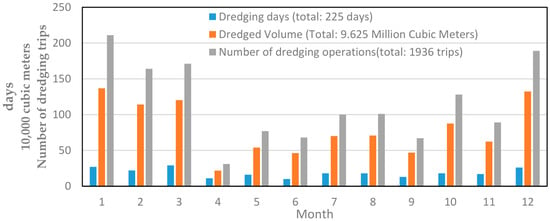
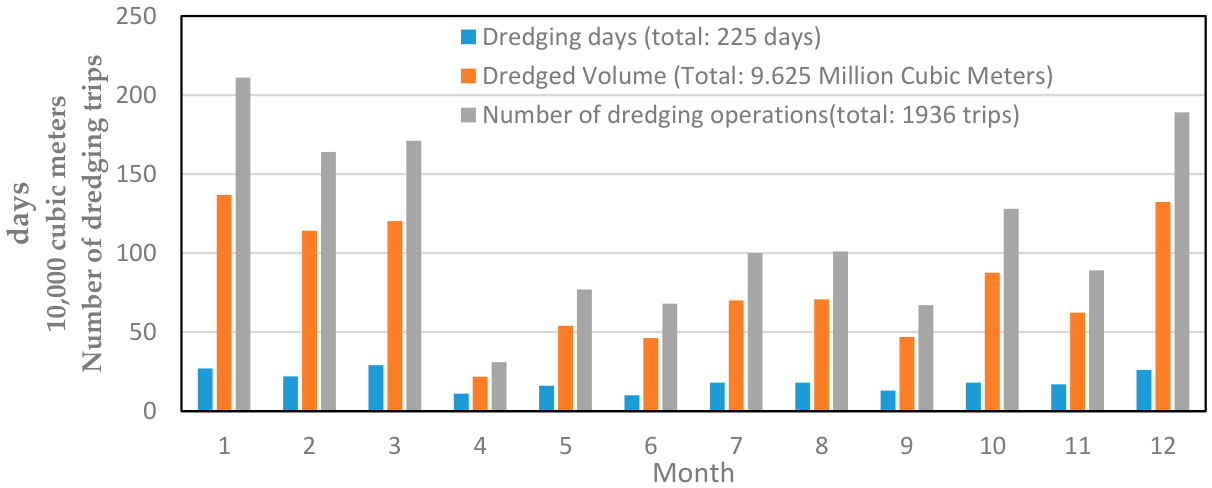
Monitoring data indicate that severe sedimentation occurred both inside the southern harbor basin and in the navigation channel area during 2023 and 2024, following the basin’s completion in June 2022. To maintain adequate water depth for vessel access and ensure unimpeded entry for LNG carriers, dredging operations were conducted for a total of 277 days in 2023, accounting for nearly 76% of the year, with 1921 dredging operations performed. In 2024, dredging was carried out over 224 days, removing a total of 9.625 million cubic meters of sediment, resulting in a daily average dredging volume of 26,400 cubic meters, as shown in Figure 5.
Figure 5.
Dredging days, number of trips, and volume in the Southern Harbor Basin in 2024.
The southern harbor basin is divided from west to east into three dredging zones: Zone 1, Zone 2, and Zone 3. The median grain sizes (D50) of the bed sediment in these three zones are 0.006 mm, 0.00613 mm, and 0.00675 mm, respectively, with an average D50 of 0.00629 mm. The proportions of fine sand, silt, and clay in the three zones are 0.1%:65.6%:34.4%, 0.15%:65.8%:34.1%, and 1.6%:66.7%:31.7%, respectively, with average proportions of 0.6%:66.1%:33.4%. This is consistent with that in the surrounding waters at depths of −10 to −15 m, classifying it as clayey silt.
Sediment disturbance during dredging operations increased the suspended sediment concentration in the water, leading to the formation of a thick fluid mud layer in the southern harbor basin, which affected channel depth and navigation safety. As the project gradually reaches full operational capacity, the frequency of LNG vessel arrivals is expected to increase significantly, making it urgent to improve the port’s sedimentation conditions.
4. Decision-Making for Determining Optimal Locations and the Construction Timing for Dynamic Interference Measures
At present, the dredging of the south basin and navigation channel of Binhai Port in Yancheng, Jiangsu Province, is carried out using mechanical dredging methods. During dredging, the disturbance of bottom sediment leads to increased suspended sediment concentration in the water body, resulting in a significant thickness of fluid mud in the basin. This affects the channel depth and navigation safety. Dredging costs account for a high proportion of maintenance expenses in heavily silted ports, even significantly reducing corporate profits. There is an urgent need to research siltation reduction strategies and develop new siltation reduction technologies for such heavily silted ports.
Currently, dynamic interference siltation reduction is a novel approach. It utilizes dynamic interference methods such as water jets or air injection to suspend sediment, followed by the use of tidal currents to transport the suspended sediment along the direction of the flow, thereby achieving the effect of reducing siltation in the basin.
Dynamic interference siltation reduction requires consideration of tidal current characteristics, flow field structures, and sediment transport pathways within the basin. The transport pathways of sediment suspended by dynamic interference vary at different locations, and even at the same location, the pathways differ depending on the timing of the suspension. Therefore, to achieve optimal siltation reduction, the scientific selection of operational locations and their corresponding operational timings is essential when employing dynamic interference methods.
Particles are released over a single tidal cycle only at different locations within the harbor basin at 10 min intervals. Each group of six particles (i.e., those released within one hour) is assigned the same color, with the earliest released particles represented in red and the latest released particles in purple. This color-coding scheme temporally tags the released particles. Using the Lagrangian particle-tracking method, the positions of the particles at different times are calculated. By observing the colors of particles that exit the harbor, it can be determined whether particles released during different tidal phases are efficiently transported out of the harbor.
The southern harbor basin has a water depth of nearly 15 m, and the sediments are predominantly fine-grained. This sediment composition is prone to flocculation [30]. The settling velocity of such sediment in similar coastal environments is approximately 0.7 mm/s [31]. Based on this settling velocity, the resuspended sediment lifted to the surface layer would take about 6 h to settle back to the bed. Given the semidiurnal tidal regime at Binhai Port, this settling duration corresponds to roughly half a tidal cycle. Particles were released at 10 min intervals from 12:00 noon over one typical tidal cycle, with simulation extended by another half cycle to 6:45 the next day.
The criterion for determining the operational time window is as follows: For each particle exported from the basin, its release time, exit time, and residence time were recorded. A release moment is feasible for dynamic interference sediment reduction if its residence time is less than 6 h. Moreover, to ensure the validity of the operational duration, the operational time window is further required to encompass a continuous 30 min feasible period.
4.1. Northern Area
A representative location in the northern part of the harbor basin was selected for particle release. Their spatiotemporal positions were tracked using the Lagrangian method, and the results are shown in Figure 6. Due to the flow field characteristics of northern inflow, southern outflow, and a central vortex structure in the harbor basin, particles released in the northern region are transported counterclockwise to the southern region during ebb tide, after which a portion is carried out of the basin. The particle transport distance is relatively long.
Figure 6.
Timing of particle release in the northern area of the Southern Harbor Basin; all particles exhibit residence times exceeding 6 h prior to basin exit, rendering this site devoid of any operational time window. (a) Within one tidal cycle, only the 3 particles released between 13:00 and 13:20 were carried out through the northern side, and only the 6 particles released 14:30 to 15:20 (orange and light brown) were carried out through the southern side. (b) Within 1.5 tidal cycles, only the particles released between 16:10 and 17:50 were carried out to the northern side.
The release time, basin exit time, and post-exit transport direction of each particle were statistically compiled, and the residence time within the harbor basin was calculated, as shown in Table 1.
Table 1.
Statistics of particle release time, basin exit time, residence time, and movement direction after exiting the basin of the station in the northern area.
As presented in Table 1, particles released during the three periods of 13:00–13:20, 14:30–15:20, and 16:10–17:50 can all be advected out of the harbor basin, with the transport directions after exiting being northward, southward, and northward, respectively. However, the residence times of these particles within the basin before exiting are 12.92 h, 6.40 h, and 9.98 h, respectively, all of which exceed 6 h. This implies that if robotic sand-raising operations were performed at this site, the tidal currents would be inadequate to effectively transport the raised sediment out of the basin before it settles back to the bed.
4.2. Central Area
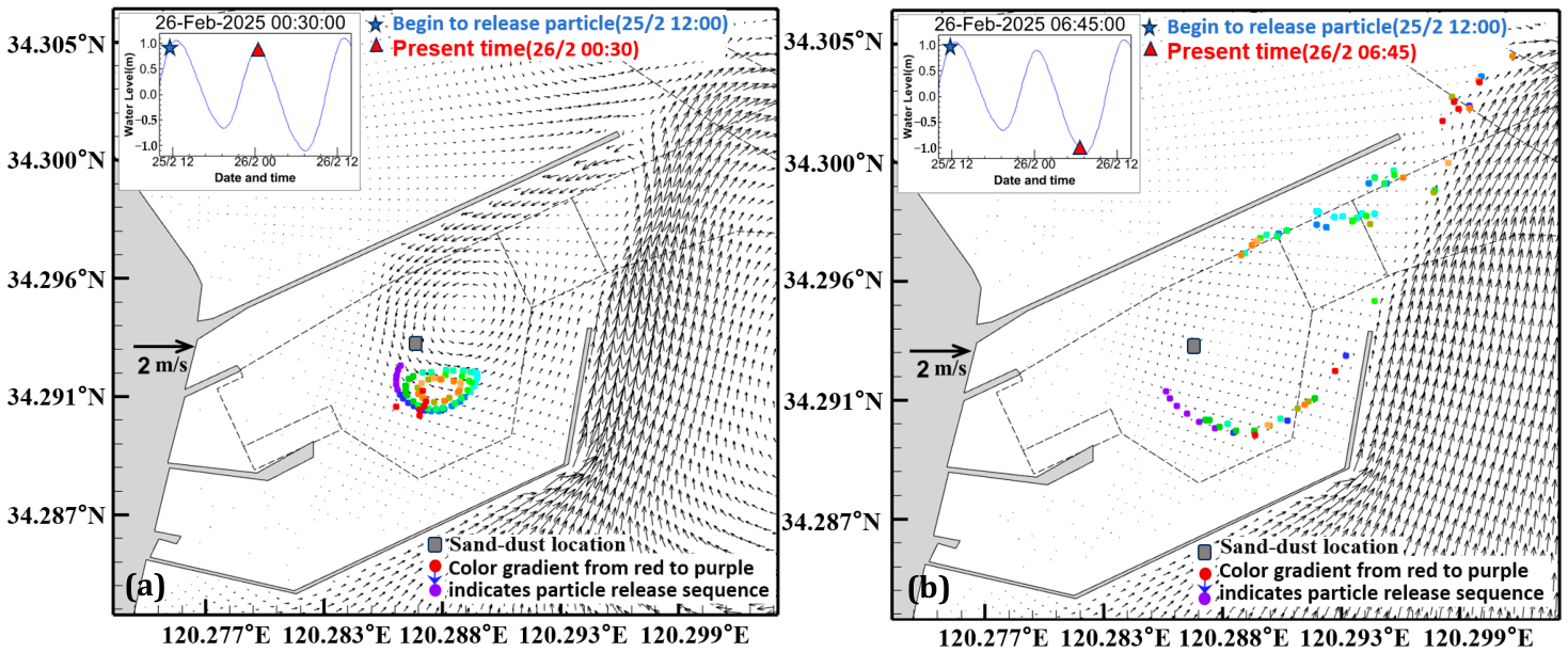
A representative location in the central area of the harbor basin was selected. Starting at 12:00 noon during high tide, particles were released continuously over a single tidal cycle only. The results are shown in Figure 7. From Figure 7a, it can be observed that, as the central part of the basin lies at the vortex center of the flow field where flow velocity remains consistently low, all released particles remain circulating and transported around the vortex center over one tidal cycle (including both ebb and subsequent flood tides), with no particles carried out of the harbor. From Figure 7b, it can be seen that after experiencing one full tidal cycle followed by an additional ebb tide—i.e., over one and a half tidal cycles—particles released at different times have the potential to be transported to the vicinity of the northern entrance, but cannot be carried out of the harbor within 6 h. Therefore, the central area of the harbor basin offers no viable operational time window for sand-dispersal activities and is consequently unsuitable as a site for dynamic interference-based sediment reduction operations.
Figure 7.
Timing of particle release in the central area of the Southern Harbor Basin. (a) After one cycle of release, all particles continue to undergo vortex motion around the center. (b) After 1.5 tidal cycles, particles begin to move outward. Particles released at various times all have the potential to be carried out. However, they cannot be carried out of the harbor basin within 6 h.
4.3. Southern Area
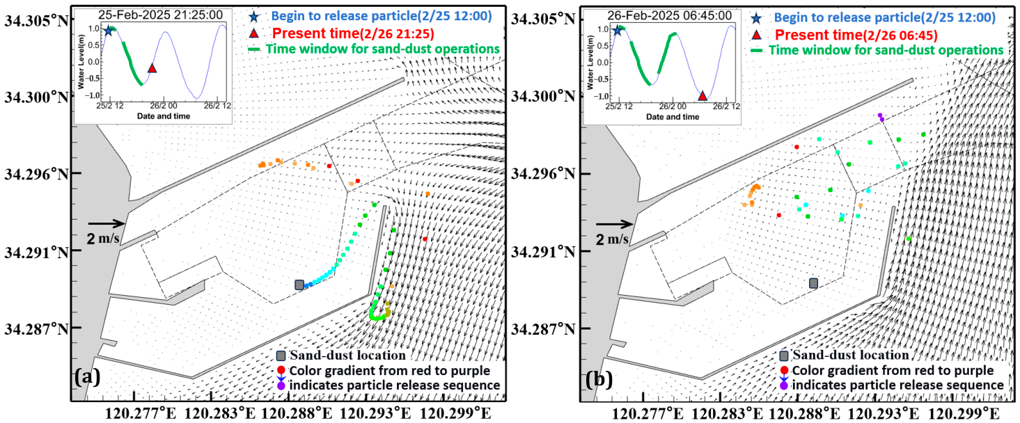
A representative location in the southern area of the harbor basin was selected. Particles were released continuously at 10 min intervals over a single tidal cycle, starting at 12:00 noon (high tide). The release time, basin exit time, and post-exit transport direction of each particle were statistically compiled, and the residence time within the harbor basin was calculated, as shown in Table 2. Following the criteria for operational time window determination, the operational time windows for the southern representative site were identified as 12:00–12:40, 15:10–19:00, and 20:30–00:20, totaling 8.33 h.
Table 2.
Statistics of particle release time, basin exit time, residence time, and movement direction after exiting the basin of the station in the southern area.
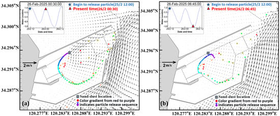
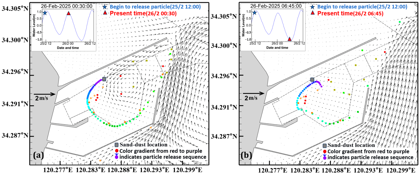
With reference to Table 2 and Figure 8a, particles released from 12:00 to 12:40 were observed to be flushed out of the harbor basin and transported northward, with a mean residence time of approximately 3.21 h. Particles released during the period of 15:10–19:00 were likewise advected out of the basin, exhibiting an average residence time of about 3.90 h; their exit occurred during the flood phase, and they were subsequently transported to the southern offshore waters. As depicted in Figure 8b, after one and a half tidal cycles, particles released between 20:30 and 00:20 were progressively carried out of the basin, with an average residence time of roughly 3.42 h. Their departure coincided with the ebb phase, and they were transported northward by the ebb current. In contrast, particles released from 12:50 to 15:00 and from 19:10 to 20:20 remained within the harbor basin even after one and a half tidal cycles, with residence times exceeding 6 h. Accordingly, these two intervals, amounting to a total of 3.34 h, are considered unsuitable for sediment dumping operations.
Figure 8.
Timing of particle release in the southern area of the Southern Harbor Basin. (a) After one tidal cycle, particles released from 12:50 to 15:00 remain inside; particles released from 12:00 to 12:40 and 15:10 to 19:00 are carried out to the southern offshore area. (b) After 1.5 tidal cycles, particles released from 20:30 to 0:20 are carried out to the northern offshore area.
5. Conclusions
The current velocity within the southern harbor basin of Jiangsu Binhai Port is low, with weak hydrodynamic conditions. The exchange of water, sediment, and other materials follows a pattern of inflow from the north and outflow from the south, forming a large-scale counterclockwise eddy in the central part of the harbor basin. Small-scale eddies exist near the entrance, resulting in complex flow field structures in this area.
At the entrance of the central harbor basin and the southern harbor basin, the layout features an enclosed planar arrangement formed by the northern breakwater, which extends further outward from the central harbor basin, and the southern breakwater of the southern harbor basin. The flow deflection effect of the northern breakwater is significant. During flood tide, the flood current flowing from northwest to southeast forms a large clockwise eddy on the western side of the entrance due to the flow deflection by the northern breakwater. During ebb tide, a counterclockwise eddy forms outside the northern breakwater as a result of its flow deflection effect. Regardless of flood or ebb tide, the flow direction outside the southern guide dike near the entrance of the southern harbor basin remains constant, always flowing northward along the dike. Due to the thick accumulation of sediment from the abandoned Yellow River estuary, this flow field characteristic is an important contributing factor to siltation in the southern harbor basin.
In the southern region of the southern harbor basin, particles released within 2.17 h after high tide turns to low tide and within 1.17 h after low tide turns to high tide cannot be taken out of the harbor basin throughout the entire tidal cycle. This means that operations are unsuitable for only 3.34 h within one tidal cycle, while particles released during most of the remaining time can be taken out. Therefore, the southern region of the harbor basin is the preferred location for operations. Particles released in the central part of the southern harbor basin move in an eddy motion and cannot be transported out of the harbor in a short time, making it unsuitable as an operational location for hydrodynamic interference to reduce siltation. Although most particles released in the northern region of the southern harbor basin cannot be transported out of the harbor within one tidal cycle, they can be quickly conveyed to the southern part of the harbor basin. Thus, sediment can be transported out of the harbor through multiple relay operations.
This study employs the Lagrangian particle tracking method to propose an approach for identifying optimal operational locations and corresponding timing for dynamic interference to reduce siltation in harbor basins characterized by fine-grained sediment accumulation. Although the gravity of sediment particles is not considered, the method provides valuable guidance for designing computational simulation schemes to evaluate siltation reduction effects in subsequent sediment modeling.
Author Contributions
Conceptualization, K.Z. and J.H.; Methodology, K.Z. and C.L. (Changgen Liu); Software, J.X.; Validation, J.X. and C.L. (Changgen Liu); Formal Analysis, J.X. and C.L. (Changgen Liu); Investigation, J.R. and J.H.; Data Curation, J.R. and C.L. (Chaoping Li); Writing—Original Draft, K.Z.; Writing—Review and Editing, C.L. (Changgen Liu); Visualization, C.L. (Chaoping Li); Supervision, C.L. (Changgen Liu). All authors have read and agreed to the published version of the manuscript.
Funding
This research received no external funding.
Data Availability Statement
The data presented in this study are available at [https://github.com/lchg-tju/Water-Article (accessed on 7 July 2026)]. These data were derived from the following resources available in the public domain: [https://github.com/lchg-tju/Water-Article/blob/main/data.zip (accessed on 7 July 2026)].
Conflicts of Interest
Authors Kezheng Zhang, Jianxun Ren, Chaoping Li and Jiaquan Hou were employed by the company CNOOC Gas and Power Group Co., Ltd., Beijing, China. The remaining authors declare that the research was conducted in the absence of any commercial or financial relationships that could be construed as potential conflicts of interest.
References
- Ren, S.; Hu, X.; Xing, L.; Lü, C.; Gao, Y. Aerodynamic dredging technology for deep water in front of three gorges reservoir. J. Yangtze River Sci. Res. Inst. 2023, 40, 24–28. [Google Scholar]
- McAnally, W.H. Managing sedimentation in federal navigation channels and harbors. J. Waterw. Port. Coast. Ocean Eng. 2016, 142, 04015013. [Google Scholar]
- Rajaratnam, N.; Mazurek, K.A. Erosion of sand by circular impinging water jets with small tailwater. J. Hydraul. Eng. 2003, 129, 225–229. [Google Scholar] [CrossRef] [Scilit]
- Qu, K.; Chen, K.; Van der Wegen, M. Impact of the permeable breakwater on spatiotemporal siltation in a semi-enclosed harbor: Case study of Binhai Harbor, China. Coast. Eng. 2026, 207, 104986. [Google Scholar] [CrossRef] [Scilit]
- Lu, C.; Jia, X.; Han, Y.; Bai, Y. Numerical simulation of sudden silting in the Yangtze Estuary deepwater channel by the wave of typhoon. Adv. Water Sci. 2018, 29, 696–705. [Google Scholar]
- Cong, X.; Zhu, W.; Gong, N.; Li, M.; Tian, A. Research review on the problem and treatment of the siltation under the tidal gate in coastal waters. J. Yancheng Inst. Technol. (Nat. Sci. Ed.) 2018, 31, 6–10. [Google Scholar]
- Xu, J.; Li, Y.; Xuan, G.; Liu, B.; Jin, Y. Study on the sediment scouring rules by dynamic water effect in approach channel under the action of ship lock sluicing. Adv. Water Sci. 2016, 27, 186–195. [Google Scholar]
- Chen, B.; Ding, L.; Ding, Y.; Yang, F.; Yang, X.; Hu, Z.L. Application of pneumatic antisilting technology in the tide gates of Xinyi River estuary hub. Jiangsu Water Resour. 2023, 11, 8–12. [Google Scholar] [CrossRef] [Scilit]
- Mikac, B.; Abbiati, M.; Adda, M. The environmental effects of the innovative ejectors plant technology for the eco-friendly sediment management in harbors. Water 2024, 16, 3574. [Google Scholar]
- Verhagen, H.J. Water Injection Dredging. In Proceedings of the 2nd International Conference on Port Development and Coastal Environment (PDCE), Varna, Bulgaria, 5–7 June 2000. [Google Scholar]
- Winterwerp, J.C.; Wang, Z.B.; van Kester, J.A.T.; Verweij, J.F. Far-field impact of water injection dredging in the Crouch River. Water Manag. 2002, 154, 285–296. [Google Scholar] [CrossRef]
- Hayes, D.F.; Crockett, T.R.; Ward, T.J.; Averett, D. Sediment Resuspension During Cutterhead Dredging Operations. J. Waterw. Port. Coast. Ocean Eng. 2000, 126, 153–161. [Google Scholar] [CrossRef] [Scilit]
- den Broeder, M.; van den Heuvel, M. UK sets global trend with water injection dredging. Port. Technol. Int. 2013, 60, 45–48. [Google Scholar]
- Chen, S.-C.; Wang, S.-C.; Wu, C.-H. Sediment removal efficiency of siphon dredging with wedge-type suction head and float tank. Int. J. Sediment Res. 2010, 25, 149–160. [Google Scholar] [CrossRef] [Scilit]
- Aderibigbe, O.O.; Rajaratnam, N. Effect of Sediment Gradation on Erosion by Plane Turbulent Wall Jets. J. Hydraul. Eng. 1998, 124, 1034–1042. [Google Scholar] [CrossRef] [Scilit]
- Yeh, P.H.; Chang, K.A.; Henriksen, J.; Edge, B.; Chang, P.; Silver, A.; Vargas, A. Large-scale laboratory experiment on erosion of sand beds by moving circular vertical jets. Ocean Eng. 2009, 36, 248–255. [Google Scholar] [CrossRef] [Scilit]
- Wang, C.; Wang, X.; Shi, W.; Lu, W.; Tan, S.K.; Zhou, L. Experimental investigation on impingement of a submerged circular water jet at varying impinging angles and Reynolds numbers. Exp. Therm. Fluid Sci. 2017, 89, 189–198. [Google Scholar] [CrossRef] [Scilit]
- Liu, S.L.; Zheng, L.; Wang, Y.; Hu, Y. Maintenance Dredging Timing of Taipingkou Waterway. Port Waterw. Eng. 2024, 9, 86–92. [Google Scholar]
- Mo, Z.; Mao, X.; Lu, C.; Wang, S. Numerical simulation study on dredging disturbance for sediment reduction in silt-prone ports and channels with high siltation. Mar. Forecast. 2025, 42, 34–45. [Google Scholar]
- Gu, B.H.; Woo, S.B.; Kwon, J.I.; Park, S.H.; Kim, N.H. Case study of contaminant transport using Lagrangian particle tracking model in a macro-tidal estuary. Water 2024, 16, 617. [Google Scholar] [CrossRef] [Scilit]
- Deltares. Port of Salaverry Siltation and Maintenance Dredging Program; Deltares: Delft, The Netherlands, 2023. [Google Scholar]
- Deltares. User Manual of Delft3D-FLOW: Simulation of Multi-Dimensional Hydrodynamic Flows and Transport Phenomena, Including Sediments; Deltares: Delft, The Netherlands, 2003. [Google Scholar]
- Zhang, M.; Wang, X.; Liu, C.; Cui, J.; Tian, Y.; Xu, X. Analysis of aquaculture safety in marine cage culture area of Maniao bay under the effect of typhoon. Appl. Ocean Res. 2024, 144, 103902. [Google Scholar] [CrossRef] [Scilit]
- Andruszkiewicz, E.A.; Koseff, J.R.; Fringer, O.B.; Ouellette, N.T.; Lowe, A.B.; Edwards, C.A.; Boehm, A.B. Modeling environmental DNA transport in the coastal ocean using Lagrangian particle tracking. Front. Mar. Sci. 2019, 6, 477. [Google Scholar] [CrossRef] [Scilit]
- Ivelina Zlateva, A.; Ricker, M. Analysis of terrestrial and riverine sources of plastic litter contributing to plastic pollution in the Western Black Sea using a lagrangian particle tracking model. Mar. Pollut. Bull. 2024, 209, 117108. [Google Scholar] [CrossRef] [Scilit]
- Cloux, S.; Perez, P. A regional Lagrangian model to evaluate the dispersion of floating macroplastics in the North Atlantic Ocean from land and river sources in the western coast of Spain. Mar. Pollut. Bull. 2024, 209, 117110. [Google Scholar] [CrossRef] [Scilit] [PubMed]
- Cox, R.X.; Senevirathna, L.; Mulligan, S.; Felder, S. Particle tracking to assess safe fish transport through closed conduit components. Ecol. Eng. 2025, 218, 107677. [Google Scholar] [CrossRef] [Scilit]
- Abbasali Rahmani, A.; Stocchino, A. Eulerian–Lagrangian simulation of wave-induced microplastic dispersion in nearshore zones: Processes and implications. Estuar. Coast. Shelf Sci. 2026, 328, 109626. [Google Scholar] [CrossRef] [Scilit]
- Tide Model Driver (TMD) Version 2.5, Toolbox. Available online: https://www.github.com/EarthAndSpaceResearch/TMD_Matlab_Toolbox_v2.5 (accessed on 24 September 2025).
- Xu, C.; Odum, B.; Chen, Y.; Yao, P. Evaluation of the Role of Silt Content on the Flocculation Behavior of Clay-Silt Mixtures. Water Resour. Res. 2022, 58, e2021WR030964. [Google Scholar] [CrossRef] [Scilit]
- Sun, J.; Wang, N.Y.; Wang, X.M. Feasibility Assessment of Dynamic Interference Sediment Reduction Technology Based on Mathematical Modeling and In-Situ Monitoring; Technical Report; Tsinghua University: Beijing, China, 2026. [Google Scholar]

Disclaimer/Publisher’s Note: The statements, opinions and data contained in all publications are solely those of the individual author(s) and contributor(s) and not of MDPI and/or the editor(s). MDPI and/or the editor(s) disclaim responsibility for any injury to people or property resulting from any ideas, methods, instructions or products referred to in the content. |
© 2026 by the authors. Licensee MDPI, Basel, Switzerland. This article is an open access article distributed under the terms and conditions of the Creative Commons Attribution (CC BY) license.