


Abstract
This study investigates the synthesis, structure, and electrochemical performance of Ni/NiO@NiS and its composite with few-layer graphene (GN) as anode materials for LIBs. Ni/NiO was first synthesized via thermal treatment, followed by the hydrothermal growth of rod-like NiS on Ni/NiO particles to form Ni/NiO@NiS. Subsequently, Ni/NiO@NiS@GN was prepared by incorporating GN into the composite. Characterization by Transmission Electron Microscope etc. confirmed the successful formation of heterostructures with mesoporous features and a specific surface area of 25.74 m2·g−1 for the GN composite. Electrochemical tests showed that Ni/NiO@NiS@GN delivered a high discharge specific capacity of 1005.6 mAh·g−1 after 100 cycles at 0.1 C and excellent rate performance (517.37 mAh·g−1 at 5 C), with a capacity recovery of 84.9% when returning to 0.1 C. The enhanced performance is attributed to the synergistic effects among Ni, NiO, and NiS, combined with GN’s high conductivity and structural buffering. This work demonstrates that GN is an optimal carbon matrix for Ni/NiO@NiS anodes.
1. Introduction
With the increasing depletion of fossil fuels and the ongoing deterioration of the ecological environment, the development of clean energy and efficient energy storage systems has become a global focus. Meanwhile, the widespread adoption of electric vehicles and the extensive use of electronic products such as smartphones, tablets, and computers have raised higher demands for the energy density, cycle life, and rate performance of energy storage systems. For an extended period, lithium-ion batteries (LIBs) have maintained a dominant position in the market due to their outstanding overall performance, establishing themselves as one of the most promising energy storage devices for mobile electronic applications and electric vehicles [1,2,3]. However, in light of the increasingly diverse application scenarios, traditional LIBs continue to encounter numerous challenges concerning capacity and rate performance, necessitating further advancements [4,5,6,7]. As a core component of LIBs, electrode materials play a decisive role in the overall performance of the battery, with research on anode materials becoming crucial for overcoming technical bottlenecks. Among various anode material systems, conversion-type anode materials have attracted significant attention from researchers due to their high theoretical specific capacity [8,9]. Since the pioneering work by the Tarascon team on transition metal oxides (TMOs) as lithium anode materials, a series of high-performance TMOs, such as NiO, TiO2, Fe3O4, and Co3O4, have been discovered [10,11]. These materials facilitate multiple electron transfer processes through reversible conversion reactions and even alloying reactions, thereby achieving specific capacities that significantly exceed those of conventional graphite anodes. Among these, nickel oxide (NiO) is considered one of the most promising anode materials for LIBs due to its low cost, straightforward synthesis process, environmental friendliness, and a theoretical specific capacity of up to 718 mAh·g−1 [12]. However, NiO still faces significant challenges in practical applications. During the charge and discharge processes, the substantial volume expansion and contraction associated with conversion reactions can lead to the pulverization of the electrode material, resulting in the loss of electrical contact between the active substance and the current collector. This ultimately leads to rapid capacity degradation and poor rate performance [13]. To address this issue, researchers have explored various modification strategies, including morphology regulation, element doping, and the construction of composite materials. For instance, the Feng Zou team successfully synthesized raspberry-like hollow Ni/NiO nanospheres anchored on graphite carbon sheets by introducing NaCl as a morphology control agent during the synthesis process. This composite material, through its unique structural design, provides more active sites and effectively buffers the volume expansion, demonstrating far superior cycling stability and reversible capacity compared to pure NiO [14]. This indicates that through rational structural design and material compounding, it is possible to overcome the intrinsic defects of NiO.
Among the various modification strategies, constructing heterostructures in conjunction with metal sulfides has been demonstrated to be an effective approach. In specific systems, the sulfide counterparts (such as NiS) exhibit higher structural stability and electrochemical reversibility compared to NiO [15]. Research has shown that combining NiO with NiS can produce a synergistic effect that significantly enhances the overall performance of the materials. The NiO-NiS nanocomposite films prepared by Dai et al. [16]. demonstrate superior electrochemical performance and cycling stability compared to individual NiO or NiS films, with the mechanism attributed to the reversible lithium reaction of both components during cycling. Wu et al. [17]. designed a hierarchical NiO@β-NiS@Ni3S2 composite material that fully utilizes the synergistic effects of the three components and the advantages of its three-dimensional structure. As a self-supporting integrated anode, it exhibits excellent lithium storage capacity and rate performance. Additionally, Zhang et al. [18]. proposed a three-dimensional nanoporous NiS/CuS pillar array structure that effectively alleviates the volume expansion stress during cycling, providing a new perspective for addressing the structural degradation of electrodes. These studies confirm that constructing binary and even multi-component composite materials, including NiS, is an effective approach to optimizing the electrochemical performance of NiO-based anodes.
Although the composite of NiO and NiS can improve electrochemical performance, the intrinsic conductivity of the materials still requires enhancement, and the volume changes during cycling need further suppression. Combining active materials with carbonaceous materials is another effective solution to address these issues [19]. Carbon materials not only possess excellent conductivity, which accelerates electron transport to enhance rate performance, but their good mechanical flexibility and high specific surface area can also buffer the volume expansion of active substances and prevent particle agglomeration, thereby maintaining the structural integrity of the electrodes [20]. In recent years, various carbon-based matrices such as graphene, graphene oxide, and carbon nanotubes have been widely applied in the modification research of NiO-based anodes. For example, Shi et al. [21] incorporated NiO nanobelts into three-dimensional graphene sheets (3DGS), effectively accommodating the volume changes in NiO due to the large pore structure of 3DGS, achieving ultra-long cycling life and exceptionally high capacity retention at high current densities. Fernando et al. [22] prepared a porous NiO/graphene composite film using electrostatic spray deposition technology, which, benefitting from the graphene nanosheets as an efficient conductive medium, significantly enhanced the reaction kinetics and rate performance of the electrode. Shao et al. [23] also noted that the synergistic effect between NiO and graphene not only enhances the conductivity of the composite material but also effectively prevents the loss of NiO particles due to volume expansion by utilizing graphene as a flexible substrate, thereby buffering the resulting stress. These studies clearly indicate that doping with carbon materials is a crucial strategy for improving the conductivity and structural stability of NiO-based anode materials.
In this study, we have rationally designed a Ni/NiO@NiS@GN nanocomposite anode material by synergistically combining Ni doping, NiS nanorod arrays, and few-layer graphene, in order to address critical issues associated with NiO-based anode materials, including poor conductivity, significant volumetric expansion, and insufficient cycling stability. The optimized Ni/NiO@NiS@GN material features a unique structure with nanorod arrays anchored within graphene, exhibiting an average pore diameter of 20.7 nm. Electrochemical evaluations demonstrate that this material exhibits outstanding performance: after 100 cycles at a current density of 0.1 C, the discharge specific capacity remains at 1005.6 mAh·g−1, with a capacity retention rate of 74.3% and an initial coulombic efficiency of 78.5%. Additionally, it possesses exceptional rate capability, with a capacity recovery rate of 84.9% when the current density is reduced from 5 C back to 0.1 C. The incorporation of metallic Ni enhances electronic conductivity, while the built-in electric field generated by the NiS heterojunction facilitates charge transfer. Furthermore, the few-layer graphene framework effectively buffers mechanical stress during cycling, reduces charge transfer impedance, and accelerates lithium-ion diffusion. Systematic characterizations using X-ray Diffraction (XRD), X-ray Photoelectron Spectroscopy (XPS), Scanning Electron Microscopy (SEM), Transmission Electron Microscopy (TEM), Brunauer–Emmett–Teller (BET), Thermal Gravimetric Analyzer (TGA), Cyclic Voltammetry (CV), Electrochemical Impedance Spectroscopy (EIS), and rate performance tests deeply elucidate the synergistic effects among Ni, NiO, NiS, and graphene. This research provides an effective strategy for the multi-component synergistic engineering design of high-performance NiO-based anodes.
2. Materials and Methods
2.1. Preparation of Ni/NiO Nanomaterials
6.664 g of C4H6O4Ni·4H2O (Manufactured by Shanghai Zhongtai Chemical Reagent Co., Ltd., Shanghai, China) was placed in a porcelain boat and heated in a muffle furnace at 300 °C for 4 h in an air atmosphere. At the reaction temperature, nickel acetate decomposes to yield organic pyrolysis intermediates, namely hydrocarbons and carbon monoxide, which collectively generate a locally confined, mildly reducing atmosphere. This ambient condition serves to inhibit the full oxidation of Ni2+, thereby enabling the survival of a small proportion of zero-valent Ni and resulting in the formation of a Ni/NiO sample. The obtained preliminary sample was then subjected to centrifugation washing three times with deionized water and anhydrous ethanol, respectively. Finally, the product was dried in a vacuum drying oven at 60 °C for 12 h to obtain the final product.
2.2. Preparation of Ni/NiO@NiS Nanocomposite Anode Materials
Ni/NiO@NiS nanocomposite anode materials were synthesized using a one-step hydrothermal method. The specific procedure involves dissolving 0.747 g of Ni/NiO material and 2.4 g of Na2S·9H2O (produced by Tianjin Baishi Chemical Co., Ltd., Tianjin, China) in 50 mL of deionized water. The solution is then stirred thoroughly for 30 min to achieve a homogeneous state. Subsequently, the prepared homogeneous solution was transferred to a stainless-steel autoclave lined with polytetrafluoroethylene (PTFE). The autoclave was then placed in an oven and heated at 160 °C for 6 h. After the autoclave naturally cooled to room temperature, the obtained sample was removed and subjected to three rounds of centrifugation washing with deionized water and anhydrous ethanol, respectively. Finally, the washed sample was dried in an oven at 60 °C for 12 h, resulting in the final product-Ni/NiO@NiS nanocomposite material.
2.3. Preparation of Ni/NiO@NiS@GN Nanocomposite Anode Materials
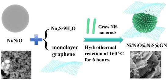
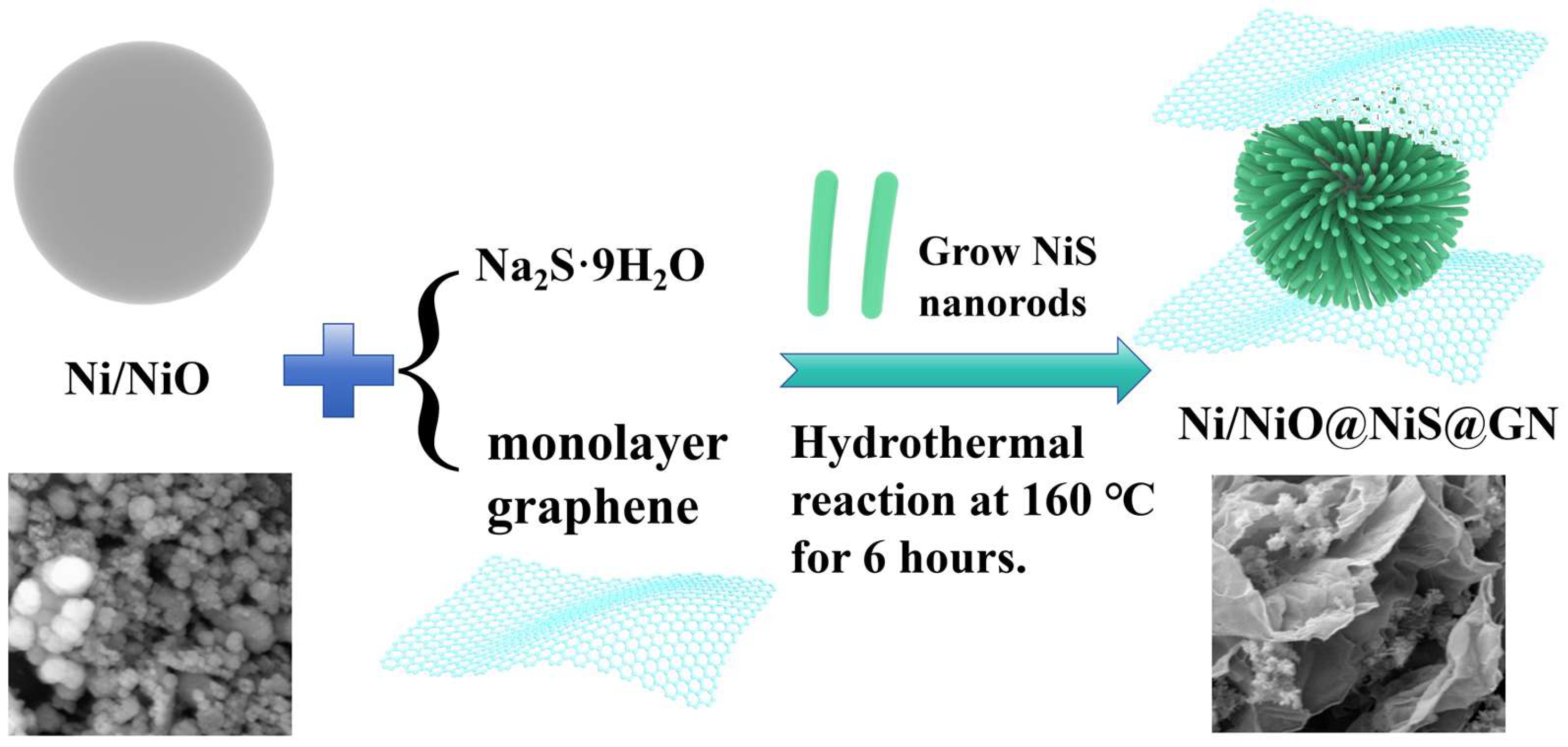
The preparation method of this material is analogous to that of the Ni/NiO@NiS materials, employing a one-step hydrothermal approach. The sole distinction lies in the additional incorporation of 0.01 g of few-layer graphene during the solution preparation process. The preparation process is shown in Figure 1.
Figure 1.
Schematic Diagram of the Synthesis Mechanism of Ni/NiO@NiS@GN Nanocomposite Material.
2.4. Material Characterizations
This study utilized various testing equipment, including the crystal structure of the samples was characterized by XRD (Bruker D8, Cu Kα radiation, 40 kV, Bruker AXS GmbH, Karlsruhe, Germany). The surface composition and chemical state were obtained by XPS (SCALAB250Xi, Thermo Fisher Scientific, Waltham, MA, USA). The SEM (JSM-6700F, JEOL Ltd., Tokyo, Japan) and TEM (JEM-2010, JEOL Ltd.), the XRD (Rigaku D/max-2400, Rigaku Corporation, Tokyo, Japan), the TGA (STA 449F3, NETZSCH-Gerätebau GmbH, Selb, Germany), and the BET surface area analyzer (TriStar 3020, Micromeritics Instrument Corp., Norcross, GA, USA) were also used.
2.5. Electrochemical Measurements
The electrochemical properties of the synthesized anode materials were evaluated using CR2032 coin-type half-cells constructed in an argon-filled glovebox. For the working electrodes, the active material, conductive carbon black, and polyvinylidene difluoride (PVDF) binder were homogeneously blended at a 7:2:1 mass ratio in N-methyl-2-pyrrolidone (NMP), followed by coating the uniform slurry onto copper foil substrates, which afforded an active material areal loading of ~1 mg·cm−2. A 1.0 M LiPF6 solution in a 1:1 (v/v) ethylene carbonate (EC)/dimethyl carbonate (DMC) blend was employed as the electrolyte. Charge–discharge cycling tests under galvanostatic conditions were carried out between 0.01 and 3.0 V on a LAND CT-2001A cycler. A CHI600E electrochemical workstation was utilized to acquire both CV curves at a scan rate of 0.1 mV·s−1 from 0.001 to 3.0 V and electrochemical impedance spectroscopy (EIS) data spanning 0.01 Hz–100 kHz.
3. Results and Discussion
3.1. Morphology and Structure Analyses
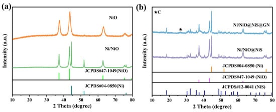
X-ray diffraction analysis was used to investigate the phase composition and crystal structure of the prepared materials, as shown in Figure 2. The diffraction patterns of the obtained Ni/NiO, Ni/NiO@NiS, and Ni/NiO@NiS@GN materials indicate that all characteristic peaks of the Ni/NiO sample match perfectly with the face-centered cubic crystal structure of NiO (JCPDS#47-1049). As shown in Figure 2a, the diffraction peaks at 37.25°, 43.28°, 62.88°, 75.41° and 79.41° correspond to the (111), (200), (220), (311) and (222) crystal planes, respectively. The additional diffraction peaks at 44.5°, 51.8° and 76.3° was exhibited in the Ni/NiO sample, which correspond to the (111), (200) and (220) crystal planes of the cubic phase Ni according to JCPDS#04-0850 [23]. Furthermore, as shown in Figure 2b, peaks at 30.3°, 32.2°, 48.8°, correspond to the (101), (300), (131), crystal planes of the rhombohedral β-NiS material (JCPDS&12-0041) [8]. Additionally, a peak around 26.38° corresponded to the (002) crystal plane of carbon, which confirms the composited graphene appeared in the samples. No other diffraction peaks were observed, indicating that the purity of the materials is high and that there are no other impurity phases present. The sharpness of the diffraction peaks indicates good crystallinity, and the crystal structure of the Ni/NiO@NiS sample did not be changed after being combined with carbon materials.
Figure 2.
(a) XRD patterns of Ni/NiO material; (b) XRD pattern of Ni/NiO@NiS and Ni/NiO@NiS@GN composite material.
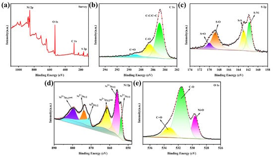
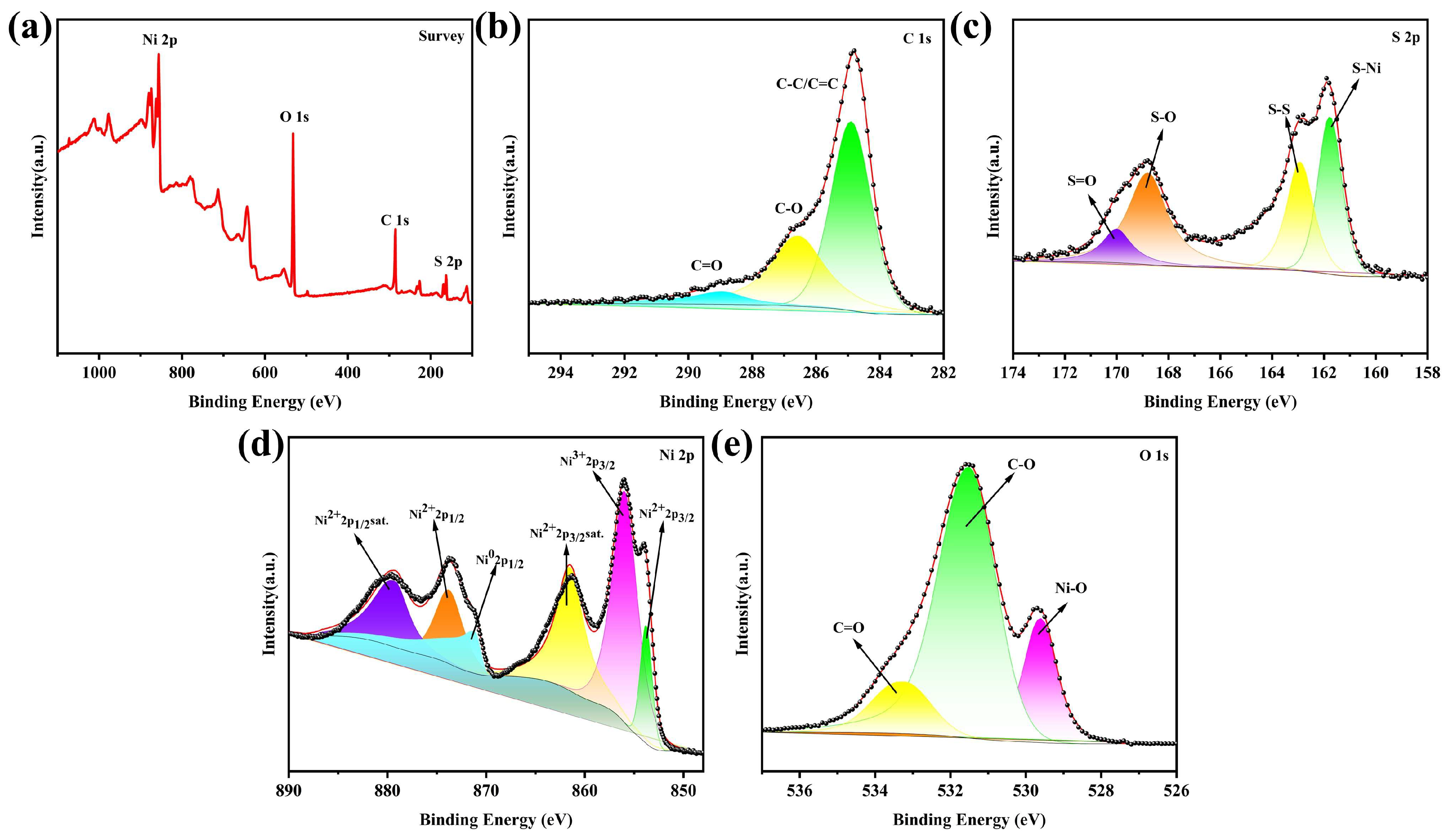
A detailed investigation of the oxidation states of elements and the chemical bonds within the synthesized Ni/NiO@NiS@GN material was conducted using XPS. As illustrated in the full spectrum of the photoelectron spectroscopy shown in Figure 3a, the Ni/NiO@NiS@GN sample contains four elements: Ni, S, C, and O. To further examine the specific oxidation states and chemical bonds of these three elements, a fine spectrum analysis was performed. As shown in the fine spectrum of C 1s in Figure 3b, the analysis reveals that the main peak at a binding energy of 284.8 eV corresponds to the C-C/C=C bond environment, which is a characteristic peak of carbon and confirms the presence of few-layer graphene within the material. A peak at 286.7 eV corresponds to the C-O bond [19], which can be attributed to the oxidation of the graphene on the material’s surface. Additionally, a feature peak appearing at 289 eV is characteristic of C=O double bond functional groups. The fine spectrum of S 2p shown in Figure 3c indicates that the peak at 161.9 eV corresponds to the S-Ni bond, thereby confirming the presence of NiS within the Ni/NiO@NiS@GN material. The characteristic peak at 163.2 eV is attributed to the S-S bond. Furthermore, the characteristic peaks at 169.1 eV and 170.2 eV correspond to the S-O and S=O bonds, respectively [24,25,26]. The fine spectrum of Ni 2p depicted in Figure 3d reveals the presence of two primary peaks corresponding to Ni3+ and Ni2+, specifically the Ni 2p3/2 and Ni 2p1/2 states, along with their satellite peaks. The two prominent peaks at binding energies of 853.9 eV and 872.9 eV are characteristic of Ni2+, while the peak at 855.7 eV corresponds to Ni3+ [27,28,29]. The formation of the Ni3+ peak is attributed to the development of oxygen-rich nickel oxides during the heating process. However, due to the coexistence of Ni and NiO phases, the amount of oxygen-rich nickel oxides is deemed negligible, a conclusion supported by the XRD results, which did not show any characteristic peaks related to oxygen-rich nickel oxides in the XRD spectrum. The satellite peaks observed at 861.0 eV and 879.2 eV correspond to the two types of Ni 2p3/2 and Ni 2p1/2, respectively. Furthermore, a significant peak at 871.2 eV represents a characteristic peak of zero-valent Ni [30,31,32], indicating the presence of a single-phase Ni within the Ni/NiO@NiS@GN material. The fine spectrum of O 1s shown in Figure 3e exhibits two prominent peaks at 529.8 eV and 531.5 eV, which correspond to the Ni-O bond and the C-O bond, respectively. The former indicates the presence of NiO in the material, while the latter can be attributed to the characteristic peak caused by adsorbed carbon dioxide in the sample. Additionally, the feature peak located at 533.3 eV is typical of the C=O double bond. These results collectively demonstrate the presence of Ni, NiO, NiS, and graphene within the Ni/NiO@NiS@GN material, consistent with the findings from the XRD results.
Figure 3.
XPS spectrum of Ni/NiO@NiS@GN materials: (a) Full spectrum; (b) C 1s high-resolution spectrum; (c) S 2p high-resolution spectrum; (d) Ni 2p high-resolution spectrum; (e) O 1s high-resolution spectrum.
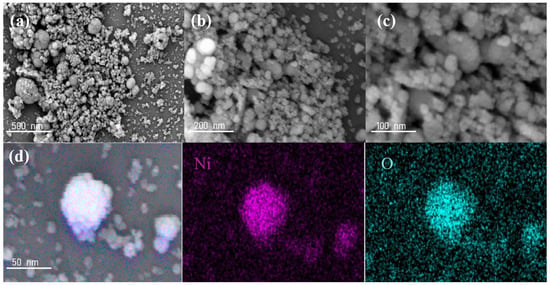
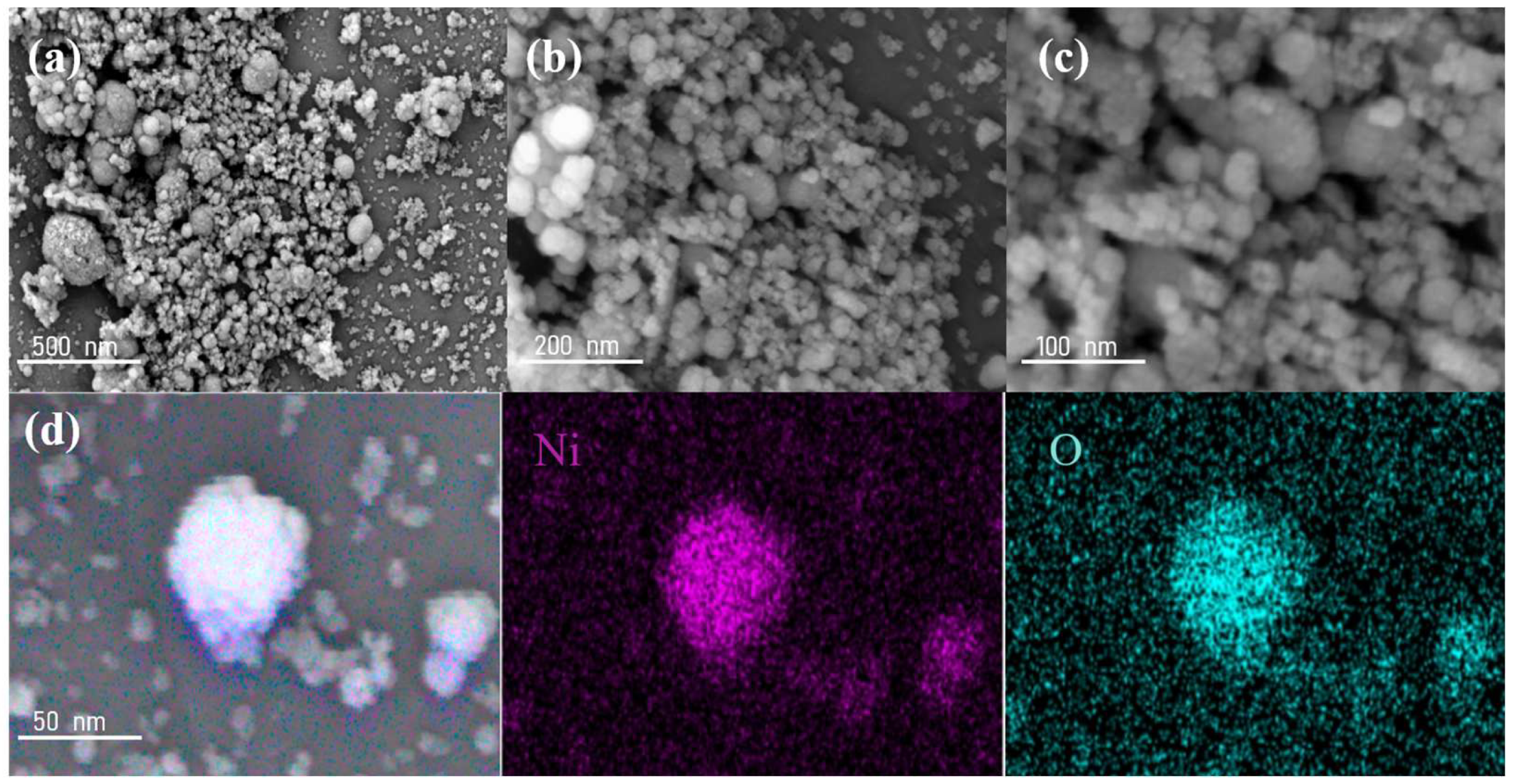
The microstructure of Ni/NiO nanomaterials was analyzed using SEM. As shown in Figure 4a–c, the Ni/NiO nanomaterials consist of numerous spherical nanoparticles with good dispersion. The diameter of each nanoparticle is approximately 30–50 nm. Generally, smaller particle sizes result in shorter diffusion paths for lithium ions, enabling faster lithium-ion migration within the small-sized particles. This leads to improved electrochemical kinetics compared to larger NiO particles, thereby exhibiting better electrochemical performance. Moreover, the relatively rough surface of the sample provides a larger specific surface area, which offers more active sites for electrochemical reactions during the electrode cycling process. As shown in Figure 4d, the energy-dispersive X-ray spectroscopy (EDS) analysis of Ni/NiO nanomaterials reveals the presence of Ni and O elements within the nanoparticles, which are uniformly distributed.
Figure 4.
Ni/NiO nanomaterials: (a–c) SEM images at different magnifications; (d) EDS elemental distribution image.
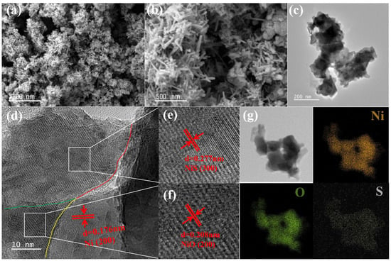
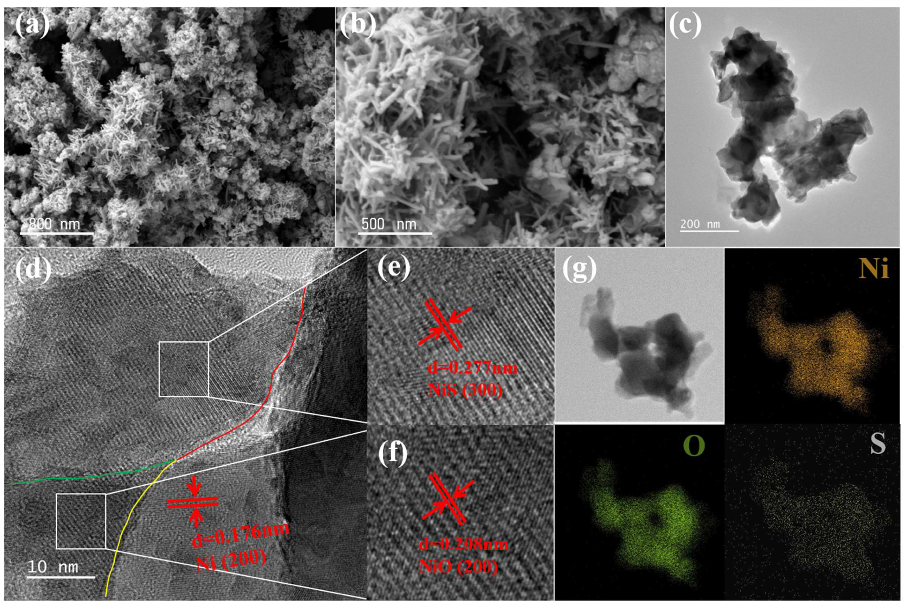
The microstructure and surface morphology of the prepared Ni/NiO@NiS nanocomposite materials were further characterized using SEM and TEM. Figure 5 show the SEM images, TEM images, and EDS spectra. As illustrated in Figure 5a, the synthesized nanocomposite materials show no obvious agglomeration and are relatively well-dispersed, with each particle having a diameter of approximately 80 nm. Furthermore, Figure 5b clearly demonstrates that the Ni/NiO@NiS nanocomposite material features rod-like NiS nanostructures growing on the spherical Ni/NiO particles, with each rod measuring around 50–100 nm in length. These nanorods contribute to a rougher surface for the Ni/NiO@NiS nanocomposite, resulting in a larger specific surface area compared to the spherical Ni/NiO particles. This increased surface area provides more active sites for electrochemical reactions, thereby enhancing its electrochemical kinetics and lithium storage capacity. To further investigate the nanoscale microstructure of the Ni/NiO@NiS nanocomposite materials, observations were made using transmission electron microscopy. As shown in Figure 5c, the TEM images clearly reveal that the Ni/NiO@NiS nanocomposite is composed of spherical Ni/NiO particles with a diameter of approximately 50 nm and rod-like NiS arrays growing on their surfaces, with lengths ranging from 50 to 100 nm. This structure not only buffers the stress generated by volumetric changes during charge and discharge cycles, making it more stable as an electrode material and reducing the likelihood of detachment from the current collector, but also interlaces the rod-like structures, further shortening the diffusion path for lithium ions. This results in faster electrolyte penetration and lithium-ion diffusion rates, significantly improving the stability and electrochemical kinetics of the lithium-ion battery. High-resolution TEM images were utilized for further analysis of the crystal structure of the Ni/NiO@NiS nanocomposite materials. As shown in Figure 5d, the phase interfaces of Ni, NiO and NiS can be distinctly observed (indicated by the red, green, and yellow curves in the image), along with the distribution of lattice fringes of different orientations, which further confirms that NiS grows on the surface of the Ni/NiO nanoparticles. Additionally, a lattice fringe spacing of approximately 0.176 nm is identified as the (200) plane of the cubic phase Ni (JCPDS#04-085). Analysis of the lattice fringes of the other two phases, shown in Figure 5e,f, indicates that a lattice fringe spacing of approximately 0.277 nm corresponds to the (300) plane of the rhombohedral β-NiS (JCPDS12-0041) material, while a lattice fringe spacing of approximately 0.208 nm is identified as the (200) plane of the face-centered cubic NiO phase (JCPDS#47-1049). Finally, the elemental composition and distribution of the Ni/NiO@NiS nanocomposite materials were characterized using EDS. The EDS elemental distribution image in Figure 5g clearly shows that the material contains Ni, O, and S elements. Furthermore, it was observed that the distributions of Ni, O, and S elements within the nanoparticles were relatively uniform.
Figure 5.
Ni/NiO@NiS nanocomposite materials: (a,b) SEM images at different magnifications; (c) TEM image; (d) high-resolution TEM image; (e,f) lattice diffraction patterns; (g) EDS elemental distribution image.
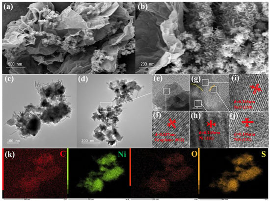
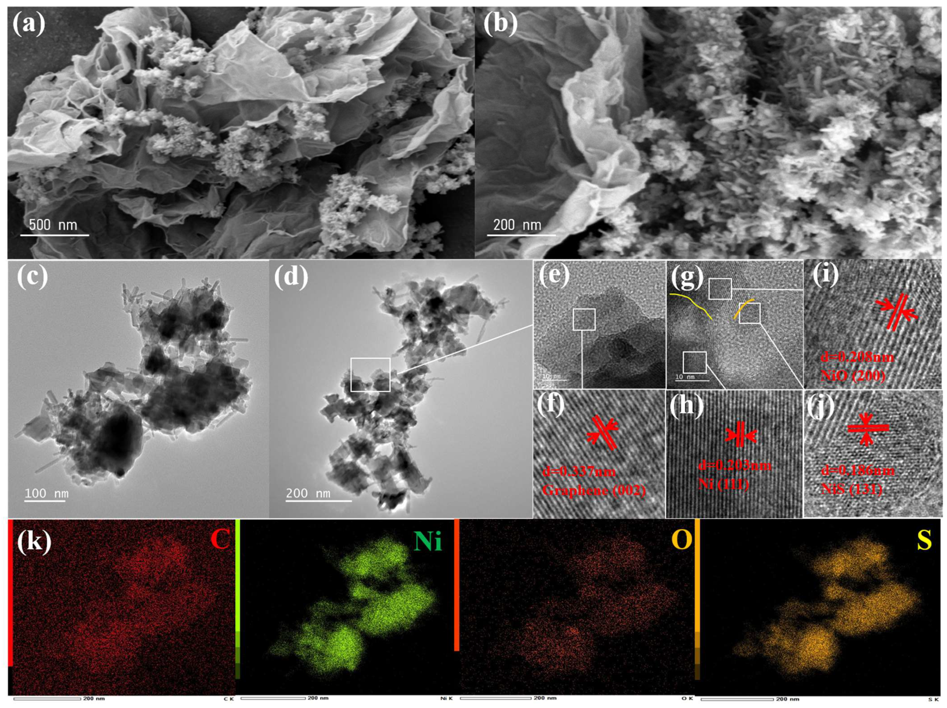
As depicted in Figure 6a,b, the morphology and structure of the Ni/NiO@NiS@GN material are characterized. In the low-magnification images, the few-layer graphene structure is clearly visible, with the Ni/NiO@NiS nanoparticles uniformly attached to the surface of the layered graphene structure. Each layer of graphene exhibits bending and folding, providing more gaps for the attachment of Ni/NiO@NiS nanoparticles. The relatively rough surfaces of the nanoparticles and the folded structure of the few-layer graphene contribute to a larger specific surface area for Ni/NiO@NiS@GN materials, which will provide more active reaction sites for electrochemical reactions. The layered graphene structure can shorten the diffusion path for lithium ions, thus increasing the lithium-ion migration rate. Furthermore, due to the stability of the few-layer graphene structure and its excellent electrical conductivity, when the Ni/NiO@NiS composite material is uniformly distributed on the surface of graphene and within the interlayer gaps, the stable framework of few-layer graphene can further enhance the conductivity and mechanical stability of the composite material. Moreover, this unique structure ensures that each layer of graphene evenly spaces the Ni/NiO@NiS composite particles apart, preventing large-scale aggregation during cycling, thereby effectively improving the electrochemical kinetics and charge–discharge cycling stability of LIBs.
Figure 6.
Ni/NiO@NiS@GN nanocomposite materials: (a,b) SEM images at different magnifications; (c,d) Low magnification TEM images; (e–j) High-resolution TEM images and their lattice diffraction patterns; (k) EDS elemental distribution image.
The Ni/NiO@NiS@GN nanocomposite material was further characterized in detail using TEM, as illustrated in Figure 6. From Figure 6c,d, it can be observed that the microstructure is similar to that of Ni/NiO@NiS, consisting of a granular Ni/NiO matrix and rod-like NiS growing on its surface. However, due to the incorporation of few-layer graphene, the presence of graphene sheets is clearly visible at the edges, as illustrated in the high-resolution image in Figure 6e. The few-layer graphene sheets are tightly integrated with the Ni/NiO@NiS particles. As shown in Figure 6f, the lattice fringe with a spacing of 0.337 nm is indexed as the (002) plane of carbon. This structure of few-layer graphene composite with Ni/NiO@NiS particles possesses a higher specific surface area, providing more active sites for electrochemical reactions during the cycling process. Additionally, it significantly buffers the mechanical stress caused by volume strain during cycling, thereby preventing the structure of the material from being damaged under high current cycling conditions, which results in improved rate performance. In Figure 6g, the interfaces between Ni, NiO, and NiS can be distinctly observed (marked by the yellow and green curves in the image). As shown in Figure 6h–j, the interplanar spacings of approximately 0.203 nm, 0.208 nm, and 0.186 nm are respectively attributed to the (111) crystal plane of the cubic phase of Ni (JCPDS#04-085), the (200) crystal plane of the face-centered cubic structure of NiO (JCPDS#47-1049), and the (131) crystal plane of the rhombohedral β-NiS material (JCPDS #12-0041). This evidence confirms that NiS grows in a rod-like structure on the granular surface of Ni/NiO, accompanied by the coating of graphene. Finally, EDS analysis was conducted to characterize the elemental composition and distribution in the Ni/NiO@NiS@GN nanocomposite materials, as shown in Figure 6k. The EDS elemental distribution image clearly shows that the material comprises four elements: Ni, O, S, and C. Further observation reveals that the distributions of Ni, O, and S elements within the nanoparticles are relatively uniform. However, the C element is exclusively present in the few-layer graphene and exhibits bending and overlapping. Additionally, there is some distribution of C in areas where Ni/NiO@NiS grains are absent. Therefore, the EDS image of C shows a minor distribution outside the Ni/NiO@NiS grains, but the majority of the C distribution exists within the regions where the Ni, O, and S elements are distributed, thus confirming that the composite material is Ni/NiO@NiS@GN.
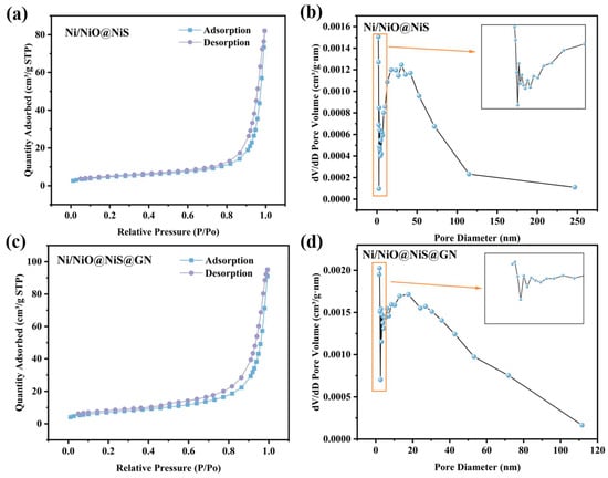
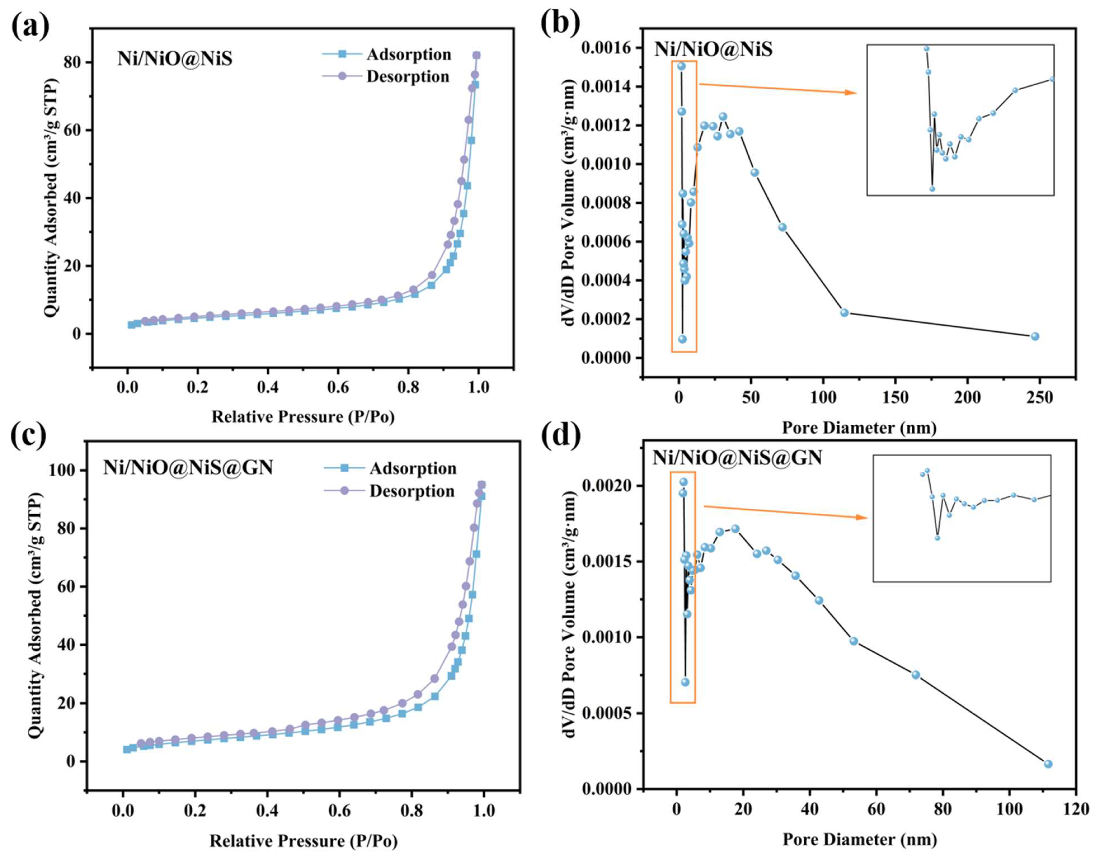
To investigate the specific surface area and pore size distribution of the Ni/NiO@NiS@GN nanocomposite material, N2 adsorption/desorption isotherms of the synthesized samples were analyzed using a surface area analyzer. The initial tests were conducted on the Ni/NiO@NiS sample (Figure 7a), where a typical Type IV isotherm curve was observed within the relative pressure range of 0.01–1 P/P0. According to the nitrogen adsorption tests, the BET specific surface area of the composite material is 16.9 m2·g−1. A larger specific surface area provides more active sites for electrochemical reactions, resulting in greater specific capacity and improved electrochemical kinetics, which allows for faster charge and discharge rates. However, a larger specific surface area can also lead to the formation of more solid electrolyte interphase (SEI) films during the first cycle, resulting in lower initial coulombic efficiency. Therefore, an appropriate specific surface area is more beneficial for enhancing electrochemical performance. Additionally, the Barrett-Joyner-Halenda (BJH) pore size distribution calculated based on the adsorption branch of the isotherm further confirms the mesoporous characteristics of the material, as shown in Figure 7b. The average pore size is 28.59 nm. Generally, microporous structures have pore sizes less than 2 nm, mesoporous structures have pore sizes ranging from 2 to 50 nm, and macroporous structures have pore sizes greater than 50 nm. Therefore, the Ni/NiO@NiS nanocomposite exhibits a mesoporous structure. A sharp peak can be clearly seen in the pore size range of 2–4 nm, attributed to the mesoporous channels in the Ni/NiO nanomaterials. The peak in the range of 6–100 nm corresponds to the pores formed by the NiS growing on the surface of Ni/NiO. Notably, mesoporous structures with high specific surface areas often play a crucial role in enhancing electrochemical activity, as they provide efficient reactant transport pathways and sufficient free space to alleviate volumetric expansion.
Figure 7.
Ni/NiO@NiS nanocomposite materials: (a) Nitrogen adsorption/desorption curves; (b) Pore size distribution. Ni/NiO@NiS@GN nanocomposite materials: (c) Nitrogen adsorption/desorption curves; (d) Pore size distribution.
The specific surface area and pore size distribution of the Ni/NiO@NiS@GN nanocomposite materials are shown in Figure 7c. A typical type IV isotherm curve is observed within the relative pressure range of 0.01–1 P/P0, accompanied by a small H3-type hysteresis loop, indicating the presence of mesoporous structures in the synthesized Ni/NiO@NiS@GN nanocomposite. The observed isotherm is consistent with a mesoporous architecture, and the accompanying H3-type hysteresis loop indicates the existence of slit-like pores, which are typically associated with the packing or agglomeration of plate-like or lamellar particles within the composite. According to the nitrogen adsorption test, the BET specific surface area of the composite material is 25.7m2·g−1, which is significantly larger than the specific surface area of the Ni/NiO@NiS nanocomposite (16.9 m2·g−1). This increase is attributed to the few-layer graphene, which provides a substantial amount of additional surface area, indicating that the material has more active sites and thus exhibits better electrochemical performance. Additionally, the BJH pore size distribution calculated based on the adsorption branch of the isotherm further confirms the mesoporous characteristics of the material, as shown in Figure 7d. The average pore size is 20.7 nm, which is smaller than that of the Ni/NiO@NiS material. This confirms that the Ni/NiO@NiS@GN nanocomposite exhibits a mesoporous structure. The smaller pore size acts as a channel for the electrolyte, accelerating the diffusion rate of lithium-ions.
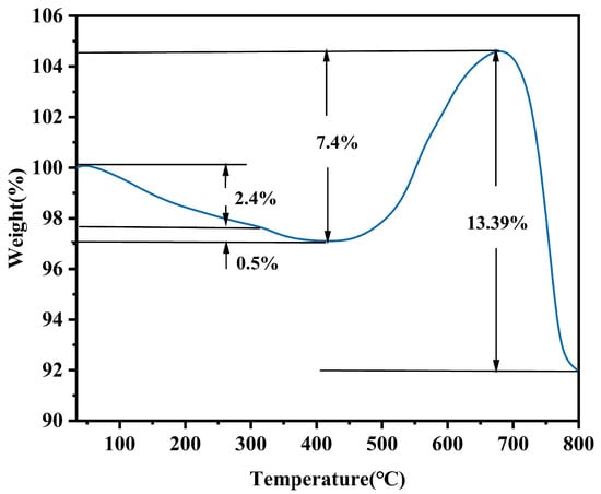
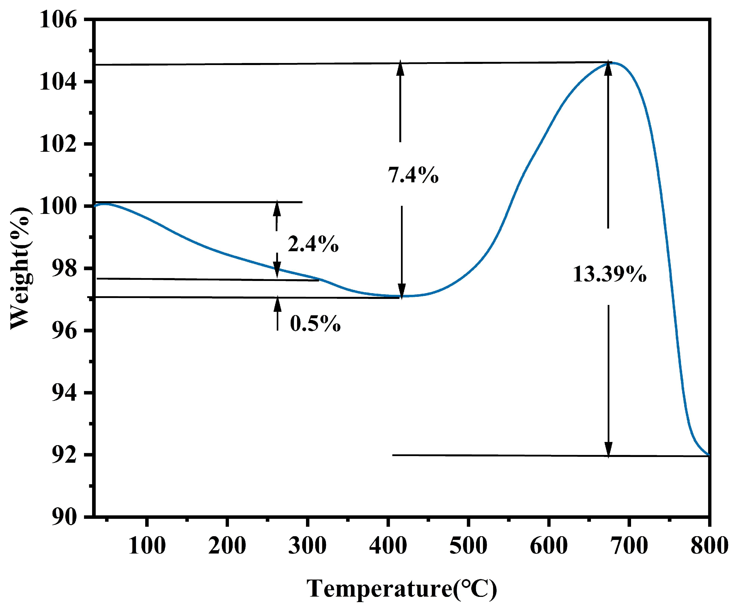
To investigate the content of graphene and other components in the Ni/NiO@NiS@GN composite material, the TGA was performed under atmospheric air conditions, as shown in Figure 8. Between 34 °C and 315 °C, the sample exhibits approximately 2.4% weight loss, which is attributed to the high-temperature evaporation of moisture adsorbed on the surface and within the pores of the composite material as the temperature increases. From 315 °C to 420 °C, a smaller weight loss of about 0.5% occurs, which can be attributed to the oxidation of NiS in the composite material to NiO due to oxygen in the air, simultaneously producing SO2 gas, as shown in Equation (1). Between 420 °C and 681 °C, there is a noticeable weight increase of approximately 7.4%, which is caused by the oxidation of Ni in the composite material to NiO, as indicated in Equation (2). From 681 °C to 800 °C, a significant weight loss of about 13.39% is observed, which can be attributed to the reaction of graphene with oxygen at high temperatures to produce carbon dioxide. From this thermogravimetric analysis, it can be concluded that the proportion of Ni/NiO@NiS@GN attributed to graphene is 13.39%. The observations indicate that (1) the weight gain observed between 420 and 681 °C can be entirely attributed to the oxidation of metallic Ni to NiO, with the oxidation reaction nearing completion within this temperature range; (2) the weight loss occurring from 681 to 800 °C can be wholly ascribed to the oxidative combustion of graphene, during which NiO remains stable; (3) the preliminary weight losses of approximately 2.4% due to dehydration and approximately 0.5% due to the oxidation of NiS do not contribute to the subsequent baseline correction calculations, as their effects on the final results are negligible, being less than 0.5%. Consequently, the carbon mass loss within the temperature range of 681 °C to 800 °C is attributed to graphene.
Figure 8.
Thermogravimetric curve of Ni/NiO@NiS@GN materials.
3.2. Electrochemical Performance
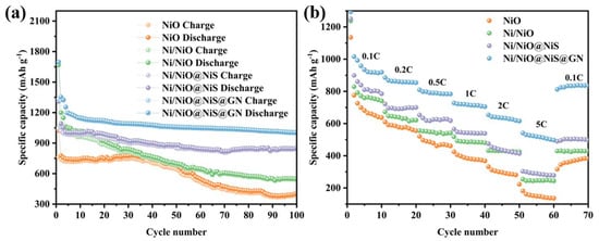
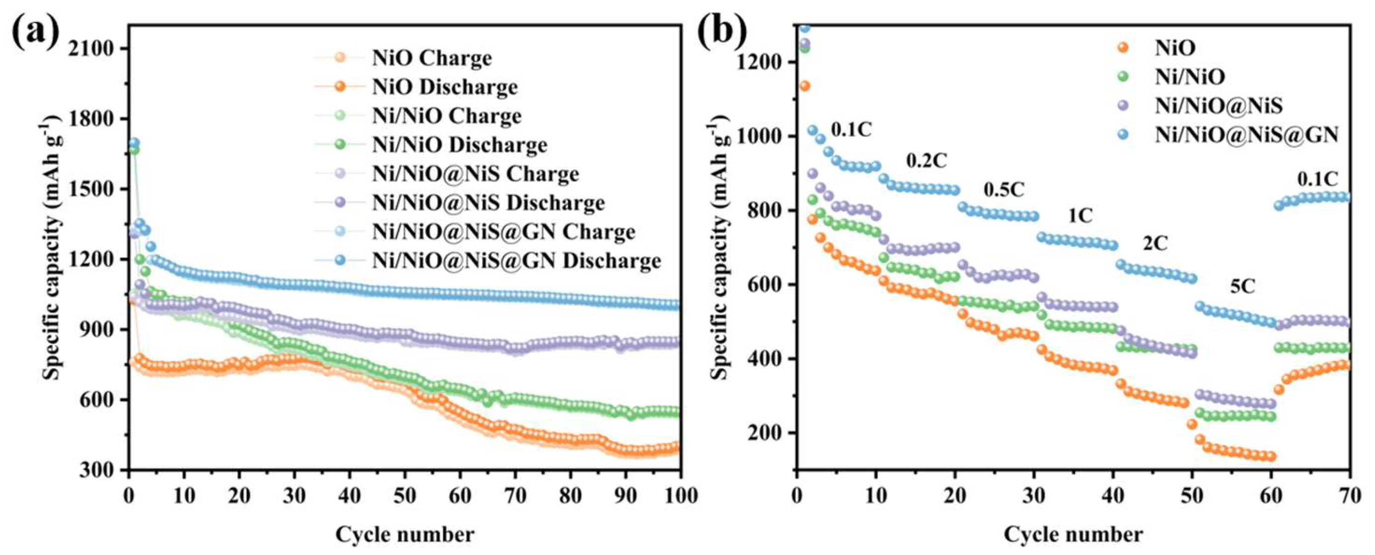
A detailed study was conducted on the cycling and rate performance, lithium storage mechanism, and electrochemical kinetics of the materials by assembling half-cells. First, a cycling test was performed on the assembled half-cells at a current density of 0.1 C within a voltage range of 0.01–3 V for 100 cycles to compare the cycling performance of the anode materials. As shown in Figure 9a, both NiO and Ni/NiO nanomaterials exhibited low initial coulombic efficiencies after the first cycle. This is attributed to limitations in reaction kinetics and the formation of the SEI film during the first discharge, which consumed a significant amount of lithium ions to form Li2O, leading to considerable capacity loss [33]. From the cycling performance curves, it can be observed that pure NiO materials have poor cycling stability, with a significant decrease in capacity after 40 cycles. This is primarily due to NiO being a semiconductor material with low conductivity and poor mechanical strength, which prevents the material from buffering the significant volume changes during cycling, causing it to collapse and detach from the current collector. Both materials exhibited low capacity retention rates. The Ni/NiO nanomaterials displayed better cycling stability, and the cycling curve showed a relatively stable trend. This is attributed to the incorporation of metallic Ni in the Ni/NiO heterostructure. On one hand, the conductivity of nickel is second only to aluminum, which enhances the conductivity of the material and increases the electron transport rate; on the other hand, the excess metallic Ni can decompose the SEI film, reducing capacity loss caused by the SEI film. The initial coulombic efficiency of the Ni/NiO@NiS nanocomposite material was 79.52%. The cycling performance curve indicates that due to its unique microstructure, it significantly buffers the pulverization of the material caused by volume strain during cycling, resulting in less electrode material detaching from the current collector. Consequently, the Ni/NiO@NiS nanocomposite material exhibits slower capacity decay and better cycling stability, along with higher capacity. After 100 cycles, the capacity retention rate was 65%, which is attributed to the synergistic effects of the three components in the composite material that facilitate reversible reactions, leading to partial decomposition of the SEI film and significantly improving the capacity and stability of the battery. Clearly, the incorporation of NiS significantly enhances the capacity and stability of Ni/NiO nanomaterials. The Ni/NiO@NiS@GN electrode material exhibits an initial coulombic efficiency of up to 78.5%. After 100 cycles, the discharge specific capacity remains at 1005.6 mAh·g−1, while the charge specific capacity is recorded at 998.6 mAh·g−1, yielding a coulombic efficiency of 99.3%. The capacity retention rate after 100 cycles is 74.3%. In comparison, the Ni/NiO@NiS@GN anode material demonstrates stable cycling performance over extended periods, characterized by consistent charge and discharge processes and minimal capacity degradation. This indicates that the doping of graphene contributes to buffering the mechanical stresses experienced by the electrode material during the charge and discharge cycles, preventing structural damage and significantly enhancing the optimization of battery capacity degradation.
Figure 9.
(a) Cycling performance of NiO, Ni/NiO, Ni/NiO@NiS and Ni/NiO@NiS@GN at a current density of 0.1 C; (b) Rate performance of NiO, Ni/NiO, Ni/NiO@NiS and Ni/NiO@NiS@GN at different current densities.
To investigate the charge and discharge performance of the four materials, charging and discharging tests were conducted within a voltage range of 0.01 to 3 V at varying current densities from 0.1 C to 5 C. As shown in Figure 9b, the Ni/NiO@NiS@GN anode material exhibited average discharge specific capacities of 978.5 mAh·g−1, 862.29 mAh·g−1, 791.31 mAh·g−1, 716.05 mAh·g−1, 633.3 mAh·g−1, and 517.37 mAh·g−1 at current densities of 0.1 C, 0.2 C, 0.5 C, 1 C, 2 C, and 5 C, respectively. In contrast, the other three materials demonstrated inferior rate capabilities at equivalent current densities. Furthermore, when the tested current density was decreased from 5 C back to 0.1 C, the discharge specific capacity was restored to 831.07 mAh·g−1, indicating a capacity recovery rate of 84.9%. In comparison, the capacity recovery rates for NiO, Ni/NiO, and Ni/NiO@NiS nanocomposites were only 49.9%, 52.5%, and 57.7%, respectively. This demonstrates that the Ni/NiO@NiS@GN anode material exhibits superior rate performance. The material enhances both electronic and ionic conductivity, allowing it to maintain a high specific discharge capacity during charge and discharge processes at both low and high current densities. Additionally, the heterojunction between NiO and NiS generates an internal electric field, further promoting the migration rate of ions and electrons within the material. In summary, the composite modification of NiS effectively enhances the rate performance of the anode material. The incorporation of few-layer graphene endows the material with a higher specific capacity, not only improving the electrical conductivity and lithium-ion diffusion properties of the Ni/NiO@NiS material but also significantly buffering the stresses encountered during the charge and discharge processes. This ensures the mechanical integrity of the material, allowing for a rapid recovery of capacity when the current density is reduced from 5 C to 0.1 C. The superior electrochemical performance of the Ni/NiO@NiS@GN anode material is primarily attributed to synergistic effects among its constituents. First, the multiphase heterointerfaces among Ni, NiO, and NiS contain abundant defects and lattice-mismatched regions, which possess higher lithium-ion adsorption energy and thus contribute additional interfacial charge storage capacity. Second, the flexible layered confinement effect of graphene restricts the active particle size to the nanoscale (approximately 50 nm), which shortens the solid-state diffusion pathways for Li+ ions and enables more NiO and NiS to participate deeply in the conversion reactions, thereby enhancing the utilization efficiency of the active materials. Finally, the strong electronic coupling effect at the triple-phase interfaces lowers the activation energy barriers of the conversion reactions, rendering certain originally irreversible reaction pathways reversible (as verified by the subsequent cyclic voltammetry curves), which further increases the effective cycling capacity.
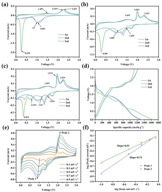
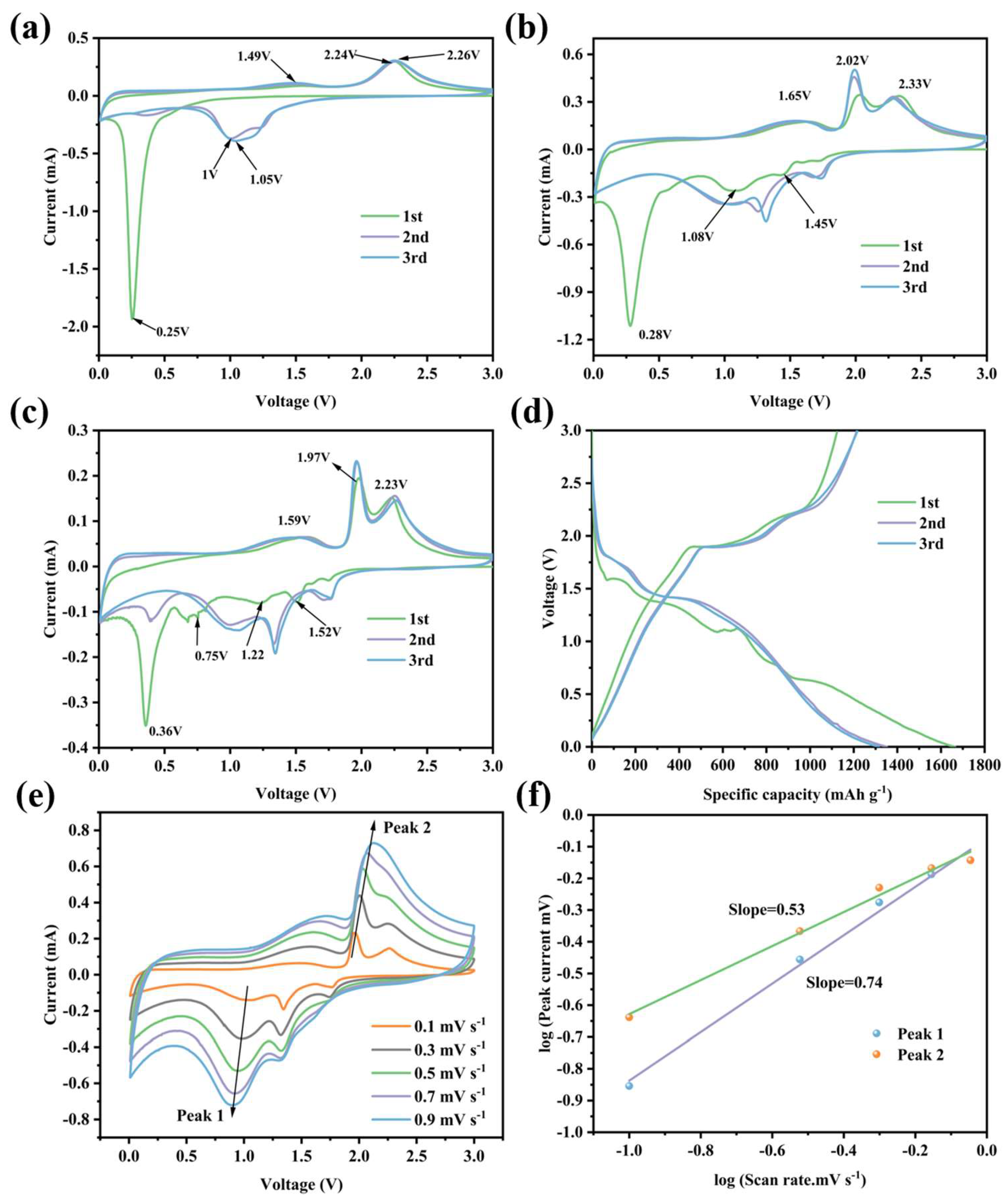
The electrochemical reactions and lithium storage mechanisms of the Ni/NiO, Ni/NiO@NiS, and Ni/NiO@NiS@GN nanocomposite anode materials during charge and discharge processes were studied using CV. The tests were conducted in a voltage range of 0.01–3.0 V with a scan rate of 0.1 mV·s−1. As shown in Figure 10a, the CV curves of the Ni/NiO anode reveals that the reduction peaks correspond to the lithium intercalation (discharge) process, while the oxidation peaks correspond to the lithium deintercalation (charge) process. During the first discharge process, three prominent current peaks can be observed. A strong reduction peak appears at 0.25 V, indicating the reduction of NiO to Ni, with Li+ converting to Li2O [34,35], as represented by Equation (3). Concurrently, this process is accompanied by the decomposition of the electrolyte at the electrode surface to form the SEI film. The oxidation peaks observed at 1.49 V and 2.24 V primarily correspond to the decomposition of the SEI film and the oxidation of Ni back to NiO, along with Li2O converting back to Li+, as represented by Equation (4) [36]. The oxidation peaks in the first cycle closely overlap with those in the subsequent two cycles; however, the reduction peaks shift to higher potentials. This shift is due to the transformation of the material from a crystalline state to a composite structure of nanoparticles with Li2O during the first cycle. This structural reorganization is not fully reversible, leading to changes in the pathways for lithium-ion intercalation/deintercalation, which raises the reduction reaction potential. Nonetheless, the voltammograms for the second and third cycles are largely overlapped, indicating that the lithium intercalation/deintercalation process of the Ni/NiO nanomaterials has stabilized.
Figure 10.
(a) The first three cyclic voltammetry curves of Ni/NiO nanomaterials; (b) The first three cyclic voltammetry curves of Ni/NiO@NiS nanocomposites; (c) The first three cyclic voltammetry curves of Ni/NiO@NiS@GN nanocomposites; (d) The first three charge–discharge curves; (e) CV curves at different scan rates; (f) Linear fitting relationship of log(i) and log(v) at the oxidation and reduction peaks.
The cyclic voltammetry curves of the Ni/NiO@NiS anode are shown in Figure 10b. In the first scan, a strong reduction peak appears at 0.28 V, corresponding to the decomposition of NiO to Ni, while also forming amorphous Li2O and the SEI film, as shown in Equation (3). In subsequent cycles, two additional reduction peaks appear at 1.08 V and 1.45 V, which are related to the two-step reaction of NiS during the discharge process [37,38], as represented by Equations (5) and (6). The oxidation peak at 1.49 V corresponds to the decomposition of the SEI film and the oxidation of Ni back to NiO, along with the conversion of Li2O to Li+, as represented in Equation (4). Additionally, a large charging current peak is observed at 2.02 V, while a smaller peak occurs at 2.33 V, associated with the extraction of Li from Li2S and the regeneration of NiS. After the first cycle, the reduction peaks shift to higher potentials, which is attributed to the transition of the material from a crystalline state to a composite structure of nanoparticles with Li2O and Li2S during the first cycle. This structural reorganization is not fully reversible, leading to changes in the pathways for lithium-ion intercalation/deintercalation, thus increasing the reduction reaction potential. However, the curves for the following two cycles approach overlap, indicating that the electrochemical reactions have stabilized.
The CV curves of the Ni/NiO@NiS@GN anodel are generally similar to those of the Ni/NiO@NiS anode, as shown in Figure 10c. Notably, during the first scan, some weak reduction peaks are observed around 0.75 V, and smaller reduction peaks appear near 0.4 V during the second scan. This can be attributed to the presence of Ni/NiO@NiS particles located deeper within the graphene interlayers, which did not fully react during the initial scan. Additionally, the SEI film near 0.36 V was not completely formed during the first scan, and in subsequent cycles, the small amount of unreacted material deeper within the graphene interlayers continued to react, forming the SEI film. After the first cycle, due to the formation of the SEI film, the reduction peaks shifted to higher potentials. Furthermore, the peak current of the oxidation process increased significantly, indicating the generation of a greater number of electrochemically active sites in the subsequent reaction processes. Meanwhile, the subsequent CV curves exhibited good overlap, fully demonstrating the excellent stability and reversibility of the Ni/NiO@NiS@GN material. Figure 10d displays the first three charge–discharge curves of the Ni/NiO@NiS@GN nanocomposite material measured at a current density of 0.1 C within a voltage range of 0.01–3 V. As shown in the figure, each plateau corresponds to the reduction peaks in the CV curves. However, the reaction platform around 0.36 V is delayed, which is due to the fast scanning rate and the incomplete first reaction after the incorporation of graphene. This platform represents the reduction of NiO to Ni, the conversion of Li+ to Li2O, and the formation of the SEI film.
To further understand the lithium-ion storage capabilities of the Ni/NiO@NiS@GN anode, the reaction kinetics were comprehensively evaluated using CV testing. CV curves were measured at different scan rates ranging from 0.1 mV·s−1 to 0.9 mV·s−1, as shown in Figure 10e. The CV curves at different scan rates exhibited consistent peak characteristics. Notably, as the scan rate increased, the peak current response significantly intensified, indicating an improvement in kinetic performance. At higher scan rates, slight shifts in the oxidation and reduction peak positions were observed, which can be attributed to the limitations of lithium-ion diffusion and electrode polarization under rapid scanning conditions. Typically, the charge storage mechanism in nanomaterials includes diffusion-controlled and capacitive-controlled processes, which can be distinguished by analyzing the relationship between peak current (i) and scan rate (v) [39], as described in Equations (7) and (8). Constants “a” and “b” play key roles in modeling electrochemical behavior.
i(v) = avb
log(i) = log(a) + blog(v)
The value of “b,” which serves as an indicator of the electrochemical mechanism, usually ranges between 0.5 and 1. It can be determined from the slope of the log(i) versus log(v) plot, as shown in Figure 10f. A “b” value close to 0.5 indicates that the capacity of the electrode is primarily diffusion-controlled, while a “b” value close to 1.0 suggests that the capacity is governed by a capacitive process. In the analysis of the Ni/NiO@NiS@GN anode, the “b” values for a reduction peak (Peak 1) and an oxidation peak (Peak 2) were calculated to be 0.74 and 0.53, respectively. These results indicate that the charge storage mechanism within the Ni/NiO@NiS@GN nanocomposite material is jointly controlled by both diffusion and capacitive processes.
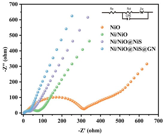
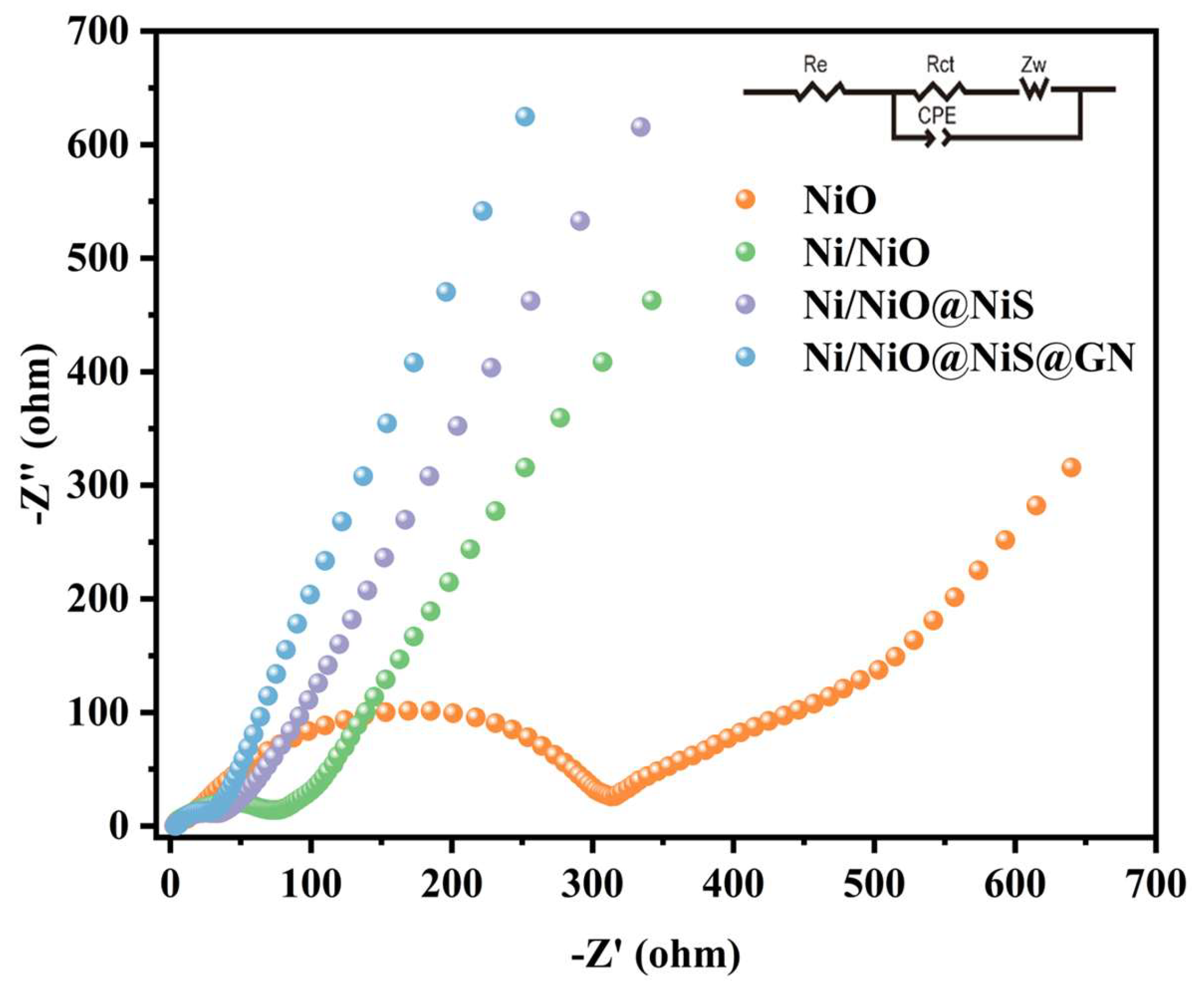
To further investigate the electrochemical performance of the materials, the EIS tests were conducted, and a comparative study was performed. As shown in Figure 11, the Nyquist curves of the two samples exhibit generally similar characteristics, consisting of a semicircle in the high-frequency region and a sloping line in the low-frequency region. The semicircle in the high-frequency region mainly corresponds to the migration process of Li+ within the electrode material, and the charge transfer resistance (Rct) at the electrode-electrolyte interface can be estimated from the diameter of the semicircle; a smaller semicircle diameter indicates a lower Rct value for the electrode [40]. The sloping line in the low-frequency region represents the Warburg impedance (Rw) [41], with a steeper slope indicating better lithium-ion diffusion performance. It can be observed that the Ni/NiO@NiS@GN electrode has the smallest semicircle radius in the high-frequency region, indicating that it has a lower charge transfer resistance. Additionally, the slope of the Warburg line in the low-frequency region for the Ni/NiO@NiS@GN electrode is greater, suggesting that its lithium-ion transport performance is better and faster. This improvement is attributed to the incorporation of few-layer graphene, which enhances the overall conductivity of the material due to graphene’s excellent conductivity, thereby reducing the charge transfer resistance. The Ni/NiO@NiS particles are well distributed within the stable framework of graphene, ensuring good overall contact and making it less likely to detach from the current collector. Furthermore, graphene provides a larger specific surface area, resulting in shorter lithium-ion transport pathways, which leads to faster lithium-ion transfer within the Ni/NiO@NiS@GN material.
Figure 11.
Nyquist plots of the NiO, Ni/NiO, Ni/NiO@NiS and Ni/NiO@NiS@GN composite anodes.
4. Conclusions
In summary, a Ni/NiO@NiS@GN nanocomposite material was successfully synthesized via a one-step hydrothermal method. This composite exhibits a unique structure in which NiS nanorods grow on the surface of spherical Ni/NiO particles, and are uniformly anchored onto a few-layer of graphene, providing a high specific surface area of 25.74 m2·g−1, abundant active sites, and enhanced structural stability. Electrochemical testing indicates that the Ni/NiO@NiS@GN anode achieves a reversible capacity of up to 998.6 mAh·g−1 after 100 cycles at a current density of 0.1 C and demonstrates outstanding rate performance (517.37 mAh·g−1 at 5 C). Moreover, when the current density is shifted from 5 C back to 0.1 C, the capacity recovery rate reaches 84.9%. The improvement in performance is attributed to the synergistic effects among Ni, NiO, and NiS, as well as the excellent conductivity of graphene and its mechanical buffering effect against volume expansion. This study provides valuable insights for the development of high-performance, long-lifespan anode materials for LIBs.
Author Contributions
Conceptualization, S.D. and Q.M.; methodology, W.D.; software, W.D.; validation, N.L., L.L. and F.Q.; formal analysis, Q.M.; investigation, Q.M.; resources, W.D.; data curation, X.T.; writing—original draft preparation, S.D.; writing—review and editing, Q.M.; visualization, W.D.; supervision, Q.M.; project administration, N.L.; funding acquisition, Q.M. All authors have read and agreed to the published version of the manuscript.
Funding
This work was financially supported by Natural Science Foundation of Henan (Grant No. 262300421976).
Data Availability Statement
The raw data supporting the conclusions of this article will be made available by the authors on request.
Conflicts of Interest
Author Qianfei Ma was employed by Henan CAERI Vehicle Testing and Certification Center Company Ltd. The author confirms that the research was conducted in the absence of any commercial or financial relationships that could be perceived as potential conflicts of interest.
References
- Fernando, N.; Kannan, H.; Robles Hernandez, F.C.; Ajayan, P.M.; Meiyazhagan, A.; Abdelkader, A.M. Graphitic Nanostructure Integrated NiO Composites for High-Performance LIBs. J. Energy Storage 2023, 71, 108015. [Google Scholar] [CrossRef] [Scilit]
- Yu, J.; Chen, X.; Wang, H.; Gao, B.; Han, D.; Si, Z. Conjugated Ladder-Type Polymers with Multielectron Reactions as High-Capacity Organic Anode Materials for LIBs. Sci. China Mater. 2022, 65, 2354–2362. [Google Scholar] [CrossRef] [Scilit]
- Masias, A.; Marcicki, J.; Paxton, W.A. Opportunities and Challenges of Lithium Ion Batteries in Automotive Applications. ACS Energy Lett. 2021, 6, 621–630. [Google Scholar] [CrossRef] [Scilit]
- Zhan, R.; Wang, X.; Chen, Z.; Seh, Z.W.; Wang, L.; Sun, Y. Promises and Challenges of the Practical Implementation of Prelithiation in Lithium-Ion Batteries. Adv. Energy Mater. 2021, 11, 2101565. [Google Scholar] [CrossRef] [Scilit]
- Lin, X.; Khosravinia, K.; Hu, X.; Li, J.; Lu, W. Lithium Plating Mechanism, Detection, and Mitigation in LIBs. Prog. Energy Combust. Sci. 2021, 87, 100953. [Google Scholar] [CrossRef] [Scilit]
- Piao, N.; Gao, X.; Yang, H.; Guo, Z.; Hu, G.; Cheng, H.-M.; Li, F. Challenges and Development of LIBs for Low Temperature Environments. eTransportation 2022, 11, 100145. [Google Scholar] [CrossRef] [Scilit]
- Zhou, Q.; Li, Q.; Liu, S.; Yin, X.; Huang, B.; Sheng, M. High Li-Ion Conductive Composite Polymer Electrolytes for All-Solid-State Li-Metal Batteries. J. Power Sources 2021, 482, 228929. [Google Scholar] [CrossRef] [Scilit]
- Singh, D.; Samtham, M.; Bisht, N.; Choudhary, E.; Kumar, V.; Jangir, R.; Sonnathi, N.; Hosmani, S.S.; Katre, A.; Devan, R.S. Theoretical and Experimental Studies on 2D β-NiS Battery-Type Electrodes for High-Performance Supercapacitor. Electrochim. Acta 2024, 506, 144998. [Google Scholar] [CrossRef] [Scilit]
- Wang, H.; Wang, Y.; Wu, Q.; Zhu, G. Recent Developments in Electrode Materials for Dual-Ion Batteries: Potential Alternatives to Conventional Batteries. Mater. Today 2022, 52, 269–298. [Google Scholar] [CrossRef] [Scilit]
- Liu, W.; Chen, L.; Cui, L.; Yan, J.; Zhang, S.; Shi, S. Freestanding 3D Nanoporous Cu@1D Cu2O Nanowire Heterostructures: From a Facile One-Step Protocol to Robust Application in Li Storage. J. Mater. Chem. A 2019, 7, 15089–15100. [Google Scholar] [CrossRef] [Scilit]
- Chen, C.; Huang, Y.; Zhang, H.; Wang, X.; Wang, Y.; Jiao, L.; Yuan, H. Controllable Synthesis of Cu-Doped CoO Hierarchical Structure for High Performance Lithium-Ion Battery. J. Power Sources 2016, 314, 66–75. [Google Scholar] [CrossRef] [Scilit]
- Hao, Q.; Wang, J.; Xu, C. Facile Preparation of Mn3O4 Octahedra and Their Long-Term Cycle Life as an Anode Material for Li-Ion Batteries. J. Mater. Chem. A 2014, 2, 87–93. [Google Scholar] [CrossRef] [Scilit]
- Park, S.-K.; Choi, J.H.; Kang, Y.C. Unique Hollow NiO Nanooctahedrons Fabricated through the Kirkendall Effect as Anodes for Enhanced Lithium-Ion Storage. Chem. Eng. J. 2018, 354, 327–334. [Google Scholar] [CrossRef] [Scilit]
- Zou, F.; Chen, Y.-M.; Liu, K.; Yu, Z.; Liang, W.; Bhaway, S.M.; Gao, M.; Zhu, Y. Metal Organic Frameworks Derived Hierarchical Hollow NiO/Ni/Graphene Composites for Lithium and Sodium Storage. ACS Nano 2016, 10, 377–386. [Google Scholar] [CrossRef] [Scilit] [PubMed]
- Sheikh, F.; Arshad, A.; Marriam, F.; Ahmad, Z.; Haider, A.; Iqbal, M.; Mansoor, M.A. Fabrication of a Nickel Sulfide/Nickel Oxide Heterostructure for Efficient Electrochemical Oxidation of Methanol. New J. Chem. 2023, 47, 17970–17983. [Google Scholar] [CrossRef] [Scilit]
- Dai, H.-Q.; Zhou, Y.-N.; Sun, Q.; Lu, F.; Fu, Z.-W. Enhanced Electrochemical Properties of NiO–NiS Nanocomposite Thin Film. Electrochim. Acta 2012, 76, 145–151. [Google Scholar] [CrossRef] [Scilit]
- Wu, X.; Li, S.; Xu, Y.; Wang, B.; Liu, J.; Yu, M. Hierarchical Heterostructures of NiO Nanosheet Arrays Grown on Pine Twig-like β-NiS@Ni3S2 Frameworks as Free-Standing Integrated Anode for High-Performance LIBs. Chem. Eng. J. 2019, 356, 245–254. [Google Scholar] [CrossRef] [Scilit]
- Zhang, Y.; Wang, H.; Zhang, S.; Liu, W. nanoporous Cu-Ni Column Arrays with Integrated NiS/CuS Composites as Anode for LIBs: A Reinforced Buffer Structure for High-Performance Electrodes. Chem. Eng. J. 2025, 509, 161003. [Google Scholar] [CrossRef] [Scilit]
- Duraisamy, E.; Sujithkrishnan, E.; Kannadasan, K.; Prabunathan, P.; Elumalai, P. Facile Metal Complex-Derived Ni/NiO/Carbon Composite as Anode Material for Lithium-Ion Battery. J. Electroanal. Chem. 2021, 887, 115168. [Google Scholar] [CrossRef] [Scilit]
- Li, X.; Fan, L.; Li, X.; Shan, H.; Chen, C.; Yan, B.; Xiong, D.; Li, D. Enhanced Anode Performance of Flower-like NiO/RGO Nanocomposites for LIBs. Mater. Chem. Phys. 2018, 217, 547–552. [Google Scholar] [CrossRef] [Scilit]
- Shi, W.; Zhang, Y.; Key, J.; Shen, P.K. Three-Dimensional Graphene Sheets with NiO Nanobelt Outgrowths for Enhanced Capacity and Long Term High Rate Cycling Li-Ion Battery Anode Material. J. Power Sources 2018, 379, 362–370. [Google Scholar] [CrossRef] [Scilit]
- Ata-ur-Rehman; Iftikhar, M.; Latif, S.; Jevtovic, V.; Ashraf, I.M.; El-Zahhar, A.A.; Abdu Musad Saleh, E.; Mustansar Abbas, S. Current Advances and Prospects in NiO-Based Lithium-Ion Battery Anodes. Sustain. Energy Technol. Assess. 2022, 53, 102376. [Google Scholar] [CrossRef] [Scilit]
- Shao, J.; Zhou, H.; Feng, J.; Zhu, M.; Yuan, A. Facile Synthesis of MOF-Derived Hollow NiO Microspheres Integrated with Graphene Foam for Improved Lithium-Storage Properties. J. Alloys Compd. 2019, 784, 869–876. [Google Scholar] [CrossRef] [Scilit]
- Fantauzzi, M.; Elsener, B.; Atzei, D.; Rigoldi, A.; Rossi, A. Exploiting XPS for the Identification of Sulfides and Polysulfides. RSC Adv. 2015, 5, 75953–75963. [Google Scholar] [CrossRef] [Scilit]
- Haghverdi Khamene, S.; Van Dalen, N.; Creatore, M.; Tsampas, M.N. Structural and Electrochemical Evolution of Nickel Sulfides During Alkaline Hydrogen Evolution Reaction. ChemSusChem 2026, 19, e202501880. [Google Scholar] [CrossRef] [Scilit] [PubMed]
- Suleimenova, D.; Tashenov, Y.; Ibrayeva, A.; O’Reilly, R.J.; Baptayev, B.; Balanay, M.P. Tailored Manganese Oxide and Nickel Sulfide Composites with MWCNTs as Platinum-Free Electrodes for Solar Energy Conversion. Sci. Rep. 2025, 15, 29723. [Google Scholar] [CrossRef] [Scilit] [PubMed]
- Zhu, Y.; Guo, H.; Wu, Y.; Cao, C.; Tao, S.; Wu, Z. Surface-Enabled Superior Lithium Storage of High-Quality Ultrathin NiO Nanosheets. J. Mater. Chem. A 2014, 2, 7904. [Google Scholar] [CrossRef] [Scilit]
- Yuan, Y.; Lu, Y.; Jia, B.-E.; Tang, H.; Chen, L.; Zeng, Y.-J.; Hou, Y.; Zhang, Q.; He, Q.; Jiao, L.; et al. Integrated System of Solar Cells with Hierarchical NiCo2O4 Battery-Supercapacitor Hybrid Devices for Self-Driving Light-Emitting Diodes. Nano-Micro Lett. 2019, 11, 42. [Google Scholar] [CrossRef] [Scilit] [PubMed]
- Zhu, J.; Li, Y.; Kang, S.; Wei, X.-L.; Shen, P.K. One-Step Synthesis of Ni3S2 Nanoparticles Wrapped with in Situ Generated Nitrogen-Self-Doped Graphene Sheets with Highly Improved Electrochemical Properties in Li-Ion Batteries. J. Mater. Chem. A 2014, 2, 3142. [Google Scholar] [CrossRef] [Scilit]
- Liu, W.; Lu, C.; Wang, X.; Liang, K.; Tay, B.K. In Situ Fabrication of Three-Dimensional, Ultrathin Graphite/Carbon Nanotube/NiO Composite as Binder-Free Electrode for High-Performance Energy Storage. J. Mater. Chem. A 2015, 3, 624–633. [Google Scholar] [CrossRef] [Scilit]
- Jiang, Z.; Liu, C.; Zhang, L.; Wei, T.; Jiang, H.; Zhou, J.; Shi, M.; Liang, S.; Zhang, S.; Fan, Z. Ultra-Small NiO Nanoparticles Anchored on Nitrogen-Doped Carbon Flowers through Strong Chemical Bonding for High-Performance LIBs. J. Power Sources 2019, 441, 227182. [Google Scholar] [CrossRef] [Scilit]
- Du, J.; Cheng, F.; Wang, S.; Zhang, T.; Chen, J. M(Salen)-Derived Nitrogen-Doped M/C (M = Fe, Co, Ni) Porous Nanocomposites for Electrocatalytic Oxygen Reduction. Sci. Rep. 2014, 4, 4386. [Google Scholar] [CrossRef] [Scilit] [PubMed]
- Liu, L.; Li, G.; Ouyang, T.; Ogundare, S.A.; Yao, X.; Balogun, M.-S.J.T. 3D Carbon Networks/NiO Nanosheets Thick Electrodes for High Areal Capacity Lithium Ion Batteries. Electrochem. Commun. 2022, 139, 107306. [Google Scholar] [CrossRef] [Scilit]
- Cao, W.; Hu, A.; Chen, X.; Liu, X.; Liu, P.; Tang, Q.; Zhao, X.S. NiO Hollow Microspheres Interconnected by Carbon Nanotubes as an Anode for Lithium Ion Batteries. Electrochim. Acta 2016, 213, 75–82. [Google Scholar] [CrossRef] [Scilit]
- Hu, Q.; Zhu, F.; Li, R.; Du, M.; Meng, Y.; Zhang, Y. Facile Synthesis of Ni-NiO/C Anode with Enhanced Lithium Storage and Long Cycling Life. Ionics 2019, 25, 5759–5767. [Google Scholar] [CrossRef] [Scilit]
- Chen, J.; Wang, Z.; Mu, J.; Ai, B.; Zhang, T.; Ge, W.; Zhang, L. Enhanced Lithium Storage Capability Enabled by Metal Nickel Dotted NiO–Graphene Composites. J. Mater. Sci. 2019, 54, 1475–1487. [Google Scholar] [CrossRef] [Scilit]
- Zhang, S.; Wang, G.; Wang, B.; Wang, J.; Bai, J.; Wang, H. Carbon Nanotube Network Bridged Hetero-Structured Ni-Fe-S Nanocubes toward High-Performance Lithium, Sodium, and Potassium Storage. Adv. Funct. Mater. 2020, 30, 2001592. [Google Scholar] [CrossRef] [Scilit]
- Guan, M.; Li, Z.; Ouyang, J.; Li, G.; Chen, L.; Zhou, M.; He, B.; Xu, W.; Wang, W.; Hou, Z. A Facile Electrospinning Strategy for Fibrous NixSy Quantum Dots @ N Doped Carbon Nanofibers as High-Performance Li-Ion Battery Anodes. Mater. Today Commun. 2022, 31, 103652. [Google Scholar] [CrossRef] [Scilit]
- Pang, M.; Song, Z.; Jiang, S.; Zhang, R.; Xi, Y.; Wu, Z.; Jiao, Y.; Zhao, J. Carbon-Coated SnS/NiS Heterostructures Scattered on the rGO Lamellas as Composite Anode for LIBs. J. Alloys Compd. 2025, 1010, 177272. [Google Scholar] [CrossRef] [Scilit]
- Wang, Y.; Roller, J.; Maric, R. Novel Flame Synthesis of Nanostructured α-Fe2O3 Electrode as High-Performance Anode for Lithium Ion Batteries. J. Power Sources 2018, 378, 511–515. [Google Scholar] [CrossRef] [Scilit]
- Lee, J.; Choi, C.; Lee, H.; Ma, S.; Tan, J.; Jang, G.; Shim, S.G.; Park, Y.S.; Yun, J.; Kim, D.; et al. Elucidating the Synergistic Behavior of Orientation-Controlled SnS Nanoplates and Carbon Layers for High-Performance Lithium- and Sodium-Ion Batteries. Adv. Energy Mater. 2022, 12, 2103138. [Google Scholar] [CrossRef] [Scilit]
Disclaimer/Publisher’s Note: The statements, opinions and data contained in all publications are solely those of the individual author(s) and contributor(s) and not of MDPI and/or the editor(s). MDPI and/or the editor(s) disclaim responsibility for any injury to people or property resulting from any ideas, methods, instructions or products referred to in the content. |
© 2026 by the authors. Licensee MDPI, Basel, Switzerland. This article is an open access article distributed under the terms and conditions of the Creative Commons Attribution (CC BY) license.