


Abstract
Lightweight polymer composites with effective electromagnetic interference (EMI) shielding are of increasing interest for advanced electronic and aerospace applications; however, conventional glass fiber-reinforced polymers (GFRPs) exhibit inherently low electrical conductivity, limiting their shielding performance. In this study, a hierarchical hybrid conductive architecture was developed by integrating graphene-coated multiaxial glass fiber fabrics with carbon black (CB)-reinforced epoxy matrices to enhance EMI shielding behavior in the X-band (8–12 GHz). Graphene coatings were deposited onto glass fibers via a surfactant-assisted ultrasonic dispersion method, while carbon black (0–1 wt.%) was incorporated into the epoxy matrix using ultrasonication-assisted mixing. Multilayer composites were fabricated using a vacuum bagging process. X-ray diffraction analysis revealed that the composites retained a predominantly amorphous epoxy/glass fiber matrix while exhibiting broad carbon-related diffraction features associated with disordered graphitic domains. Electrical conductivity measurements indicated that all composites remained in the insulating regime (~10−9 S/m), suggesting that a fully interconnected conductive network was not established within the investigated filler range. Despite the absence of a continuous conductive network, measurable EMI shielding performance was achieved. The composite containing 0.25 wt.% CB exhibited the highest shielding effectiveness, reaching approximately 12 dB at ~11.2 GHz. Analysis of the shielding contributions showed that absorption contributions (SEA) were consistently higher than reflection contributions (SER) across the studied frequency range. Morphological observations revealed that well-dispersed CB at low loading facilitated the formation of localized conductive domains that may contribute to tunneling-assisted polarization and interfacial charge accumulation. At higher CB contents, particle agglomeration reduced dispersion quality and limited effective pathway formation, while dynamic mechanical analysis indicated enhanced stiffness at low CB loading. FTIR results confirmed the absence of new chemical bonding, indicating that CB acts as a physically dispersed conductive filler. Overall, the results show that effective EMI shielding can be achieved in electrically insulating composites through the combined effect of hierarchical structural design and localized conductive features. This approach provides a practical pathway for developing lightweight EMI shielding materials with controlled filler loading and preserved structural integrity for aerospace and electronic applications.
1. Introduction
The rapid expansion of wireless communication systems, high-frequency electronics, and aerospace technologies has increased the demand for materials capable of mitigating electromagnetic interference (EMI). Uncontrolled EMI can degrade device performance, reduce signal integrity, and compromise the reliability of sensitive electronic systems. Consequently, the development of lightweight, corrosion-resistant, and structurally robust materials with effective EMI shielding capability has become an important research focus [1,2,3].
Glass fiber-reinforced polymer (GFRP) composites are widely used in aerospace, transportation, and structural applications because of their favorable mechanical performance and low density. However, their inherently low electrical conductivity limits their EMI shielding capability [4,5,6]. To overcome this limitation, conductive carbon-based fillers such as carbon black (CB), carbon nanotubes, and graphene have been incorporated into polymer matrices to promote electromagnetic attenuation [7,8,9,10]. Conventional EMI shielding strategies typically rely on conductive filler concentrations above the electrical percolation threshold, where a continuous conductive network is established, and shielding is primarily associated with conduction and reflection mechanisms [11,12]. Nevertheless, increasing filler loading often promotes agglomeration, processing difficulties, and deterioration of other functional properties. Recent studies have therefore explored hierarchical and multiscale composite architectures that combine conductive coatings with dispersed conductive fillers to enhance electromagnetic attenuation at lower filler concentrations [13,14,15,16,17,18,19,20].
Recent investigations have demonstrated that effective EMI shielding does not necessarily require the formation of a fully interconnected conductive network. In electrically insulating composites operating below the percolation threshold, electromagnetic attenuation may still occur through dielectric-loss-related mechanisms such as interfacial polarization, dipolar relaxation, tunneling-assisted charge displacement, and multiple internal reflections [21,22,23,24]. However, the combined influence of hierarchical architecture, filler dispersion, agglomeration behavior, and interfacial interactions on EMI shielding performance remains insufficiently understood, particularly in multilayer composite systems operating within the X-band frequency range (8–12 GHz) [25,26,27].
In this study, graphene-coated multiaxial glass fiber fabrics and carbon black-reinforced epoxy matrices were combined to develop hierarchical composite structures for EMI shielding applications. Multilayer composites containing different CB loadings (0–1 wt.%) were fabricated via vacuum bagging and systematically characterized using SEM, FTIR, DMA, electrical conductivity measurements, and vector network analyzer (VNA)-based EMI shielding analysis. Electrical measurements confirmed that all formulations remained below the electrical percolation threshold, allowing the influence of non-percolative attenuation mechanisms to be investigated. The novelty of this work lies in demonstrating that measurable and absorption-dominated EMI shielding can be achieved while maintaining the electrically insulating character of the composite system. The findings provide new insight into the role of interfacial polarization, localized carbonaceous regions, and hierarchical structural design in the development of lightweight multifunctional shielding materials for aerospace and advanced electronic applications.
2. Experimental Details
2.1. Materials
Multiaxial E-glass fiber fabrics with an areal density of 1238 g/m2 (FiberElyaf Market, Kocaeli, Türkiye) were used as the reinforcement material for composite fabrication. The matrix system consisted of a low-viscosity epoxy resin (F-1564) and its corresponding amine hardener (F-3486) supplied by Fibermak Composites (İzmir, Türkiye). According to the manufacturer’s specifications, the epoxy resin exhibits a viscosity of 1200–1400 mPa·s and a density of approximately 1.15 g/cm3 at 25 °C. The epoxy and hardener were mixed at a weight ratio of 100:34, following the manufacturer’s recommendation.
Conductive carbon black (VULCAN XCmax™ 22, Cabot Corporation, Alpharetta, GA, USA), a high-conductivity specialty carbon black, was employed as a secondary conductive filler within the epoxy matrix. Few-layer graphene powder (N006-P, Angstron Materials, Dayton, OH, USA) was used for the surface modification of glass fiber fabrics. According to the supplier specifications, the material possesses a carbon purity of ≥98 wt.%, oxygen content ≤2 wt.%, specific surface area >20 m2/g, and a median particle size (D50) of approximately 9 ± 1 µm. Isopropyl alcohol (IPA, Merck, Darmstadt, Germany) was used as the dispersion medium during the graphene coating process, while sodium dodecyl sulfate (SDS, Sigma-Aldrich, St. Louis, MO, USA) was employed as a surfactant to improve graphene dispersion stability.
2.2. Graphene-Coated Glass Fibers
Prior to composite fabrication, graphene coating optimization studies were conducted using different graphene concentrations. Few-layer graphene (FLG) was dispersed in 400 mL of isopropyl alcohol containing 0.4 g SDS. The suspension was ultrasonically treated using an ultrasonic bath (SK5210LHC, operating frequency: 35.53 kHz, ultrasonic power: 200 W) at 30 °C for 1.5 h to ensure homogeneous surfactant distribution.
Subsequently, few-layer graphene (FLG) was added to the suspension, and ultrasonication was continued for an additional 1.5 h. Graphene concentrations of 0.025 g, 0.05 g, 0.075 g, and 0.1 g were investigated. Finally, glass fiber fabrics and glass substrates were immersed in the graphene suspension and maintained under ultrasonic treatment for a further 1.5 h to promote uniform coating deposition.
The selection of the optimum graphene concentration was based on preliminary characterization studies involving SEM observations, contact angle measurements, and electrical resistance analysis. The graphene amount reported in this section refers to the quantity introduced into the coating dispersion system rather than the exact mass deposited on the fiber surface.
2.3. Fabrication of Hybrid Composites
Graphene-coated glass fiber fabrics were used to fabricate multilayer composite laminates. Each laminate consisted of three graphene-coated glass fiber layers arranged in a symmetric stacking sequence. The fiber architecture, number of reinforcement layers, and resin-to-fiber ratio were maintained constant for all formulations to ensure that the influence of carbon black content could be evaluated independently.
The epoxy resin and curing agent were mixed according to the manufacturer’s recommended ratio (epoxy:hardener = 100:34 by weight). Carbon black (CB) was incorporated into the epoxy matrix at concentrations of 0, 0.25, 0.5, and 1 wt.% relative to the resin system. To promote homogeneous filler distribution, the CB/epoxy mixtures were ultrasonicated for 30 min at a nominal power of 320 W prior to laminate fabrication.
The resulting CB-filled epoxy suspensions were applied between the graphene-coated fiber layers to achieve uniform impregnation of the reinforcement architecture. Composite laminates were subsequently manufactured using a vacuum bagging process to improve consolidation and minimize entrapped air within the laminate structure.
After curing, composite plates with approximate dimensions of 18 × 27 cm were obtained. The measured laminate thickness varied between approximately 2.39 and 3.16 mm (Table 1). These variations are attributed to local differences in resin flow, compaction behavior, and fiber packing during vacuum-assisted processing rather than differences in formulation. The fabricated composites were designated as E0 (0 wt.% CB), E25 (0.25 wt.% CB), E50 (0.5 wt.% CB), and E1 (1 wt.% CB).
Table 1.
Thickness, median resistance, resistivity, and electrical conductivity values of the fabricated composites.
2.4. Materials Characterization
The structural characteristics of pristine carbon black and the fabricated composites were investigated by X-ray diffraction (XRD) using a Rigaku D/Max-2200/PC diffractometer (Rigaku Corporation, Tokyo, Japan) equipped with Cu Kα radiation. Measurements were performed at 40 kV and 36 mA over a 2θ range of 3–90° with a scanning step size of 0.02°.
Electrical characterization was conducted at room temperature using a S302-6 four-point probe system (Lucas Labs, Gilroy, CA, USA). Measurements were performed at multiple locations on each specimen to evaluate repeatability and spatial variability. The median resistance values were used to calculate electrical resistivity, considering the measured sample thickness, and electrical conductivity was subsequently determined as the inverse of resistivity. The reported conductivity values correspond to bulk (volume) conductivity calculated from the measured sample thickness and electrical resistance data.
The surface morphology of the composites and the dispersion state of carbon black within the epoxy matrix were examined using scanning electron microscopy (SEM) using a ZEISS GeminiSEM 300 field-emission scanning electron microscope (Carl Zeiss AG, Oberkochen, Germany). Prior to imaging, the specimens were coated with a thin conductive layer to minimize charging effects. SEM observations were used to evaluate filler distribution, agglomeration behavior, and microstructural features of the composite system.
Fourier transform infrared (FTIR) spectra were collected in attenuated total reflectance (ATR) mode using a Nicolet iS50 FTIR spectrometer (Thermo Fisher Scientific, Madison, WI, USA) to identify characteristic functional groups and evaluate possible changes associated with filler incorporation. Dynamic mechanical analysis (DMA) was performed using a Q800 Dynamic Mechanical Analyzer (TA Instruments, New Castle, DE, USA) to determine the storage modulus (E′), loss modulus (E″), and loss factor (tan δ) as a function of temperature. The glass transition temperature (Tg) was obtained from the maximum of the tan δ curve.
The electromagnetic interference (EMI) shielding performance of the composites was evaluated in the X-band frequency range (8–12 GHz) using a PNA-L N5230C Vector Network Analyzer (Agilent Technologies, Santa Clara, CA, USA) and a WR-90 rectangular waveguide. Composite specimens were machined to dimensions of 22.86 mm × 10.16 mm to ensure proper waveguide fitting. Prior to testing, a full two-port Short–Open–Load–Thru (SOLT) calibration procedure was performed. For each formulation, at least three independent specimens were measured, and the reported values correspond to the average response.
The total shielding effectiveness (SET) was calculated from the transmission coefficient according to:
SET = −10 log10(|S21|2)
The reflection coefficient (R) and transmission coefficient (T) were obtained from:
while the absorption coefficient was calculated as:
R = |S11|2
T = |S21|2
A = 1 − R − T
The shielding effectiveness contributions associated with reflection (SER) and absorption (SEA) were calculated according to:
SER = −10 log10(1 − R)
SEA = −10 log10(T/(1 − R))
The calculated values satisfy the relationship:
SET = SER + SEA
3. Results and Discussion
3.1. XRD Structural Analysis
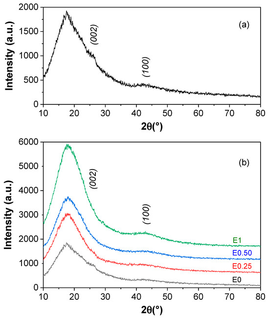
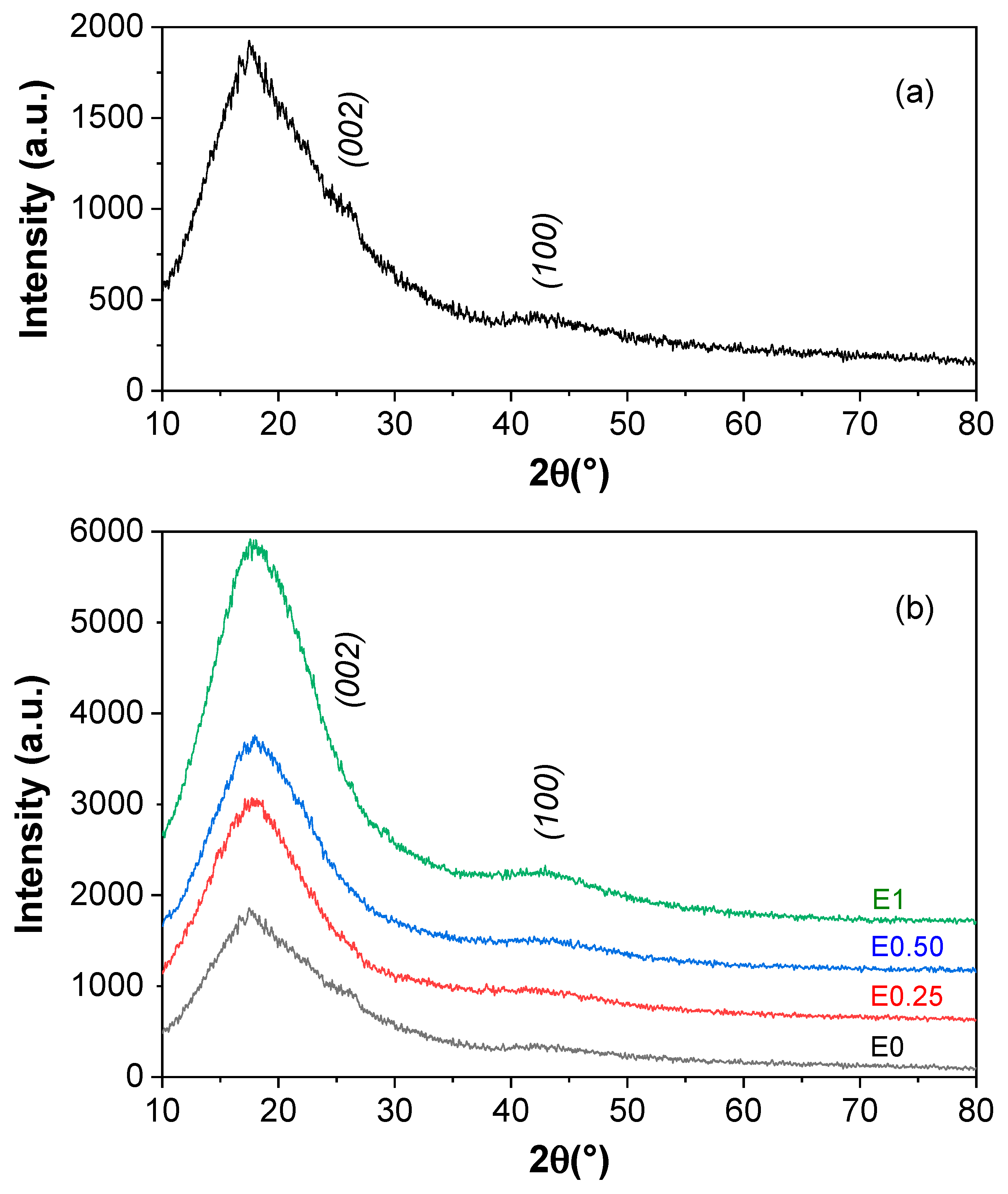
X-ray diffraction (XRD) analysis was performed to investigate the structural characteristics of pristine carbon black (CB) and graphene-coated glass fiber/epoxy composites containing different CB loadings. The corresponding diffraction patterns are presented in Figure 1.
Figure 1.
XRD patterns showing the structural features of (a) pristine carbon black (CB) and (b) graphene-coated glass fiber/epoxy composites reinforced with different carbon black loadings.
The diffraction pattern of pristine CB (Figure 1a) exhibits broad diffraction features rather than sharp crystalline peaks. A broad contribution is observed within the 2θ range of approximately 15–30°, corresponding to the graphitic (002) diffraction region, while a weak feature near 2θ ≈ 42–44° can be associated with the graphitic (100) reflection. The broad nature of these peaks indicates a predominantly disordered carbon structure with limited graphitic ordering, which is characteristic of conductive carbon black materials [28].
The diffraction patterns of the composite laminates (Figure 1b) are dominated by a broad amorphous halo centered around 2θ ≈ 18–20°, originating primarily from the epoxy matrix and glass fiber reinforcement. No sharp crystalline peaks were detected, indicating that the overall composite structure remained predominantly amorphous after the incorporation of carbon-based fillers. Similar diffraction behavior has been reported for epoxy-based composites containing carbonaceous nanofillers, where the polymer matrix remains structurally amorphous despite filler incorporation [28].
As the CB content increased, a slight increase in diffraction intensity was observed within the graphitic diffraction regions. However, these features remained broad and diffuse, suggesting the presence of localized carbonaceous regions rather than the formation of a highly ordered or continuous graphitic structure. This observation is consistent with the electrical conductivity results, which showed that all formulations remained within the insulating regime and did not exhibit an electrical percolation transition.
The coexistence of an amorphous polymer matrix and dispersed carbonaceous regions creates structural heterogeneity within the composite architecture. Such heterogeneous interfaces may contribute to dielectric-loss-related attenuation mechanisms under electromagnetic excitation. Therefore, the XRD results support the interpretation that the EMI shielding behavior of the developed composites is associated primarily with interfacial interactions and localized carbon-rich regions rather than the formation of a continuous conductive network. The absence of sharp graphitic reflections further confirms that the incorporated carbonaceous fillers remained largely disordered within the epoxy matrix.
3.2. Electrical Conductivity Results
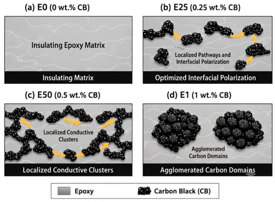
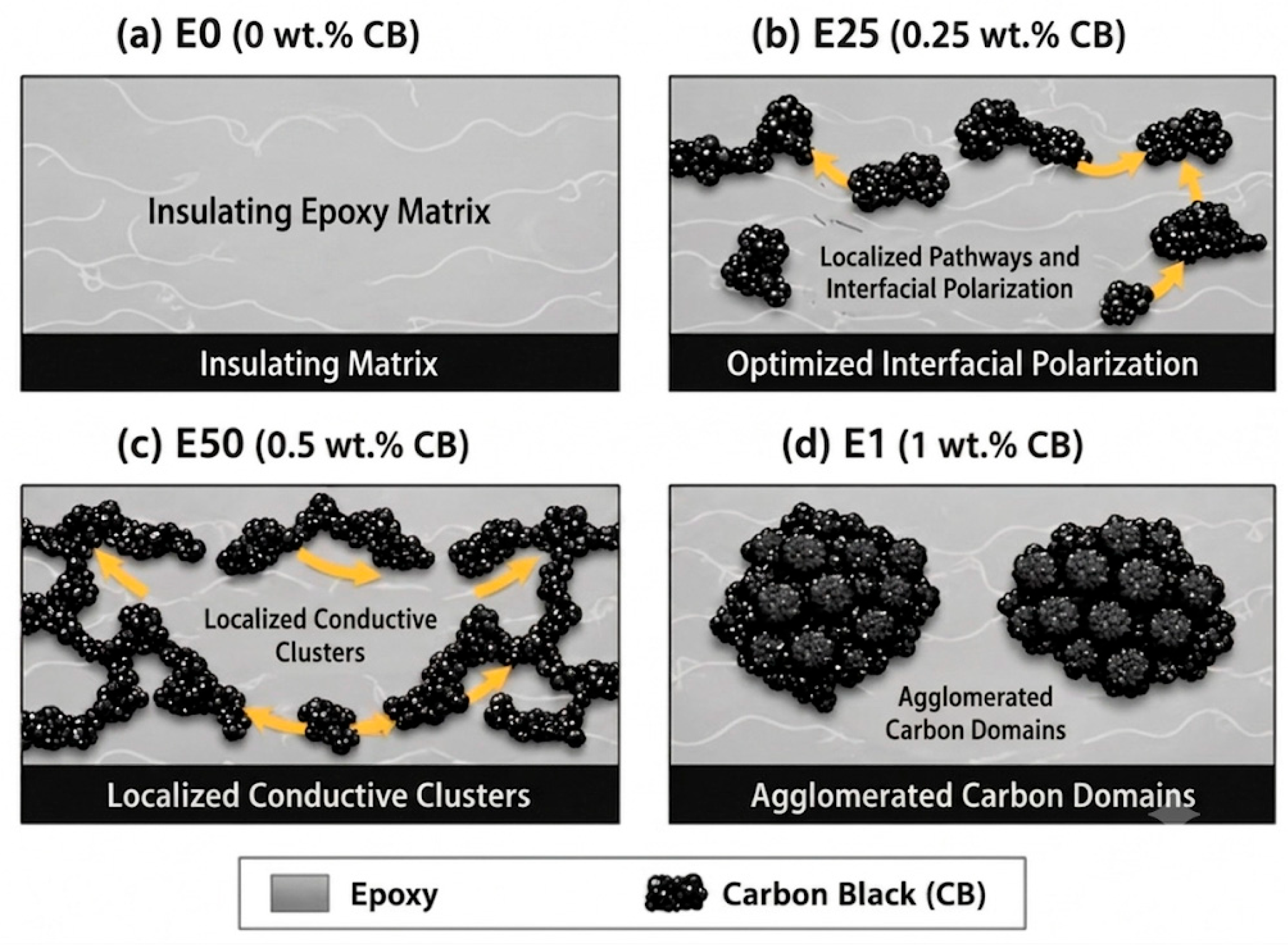
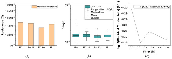
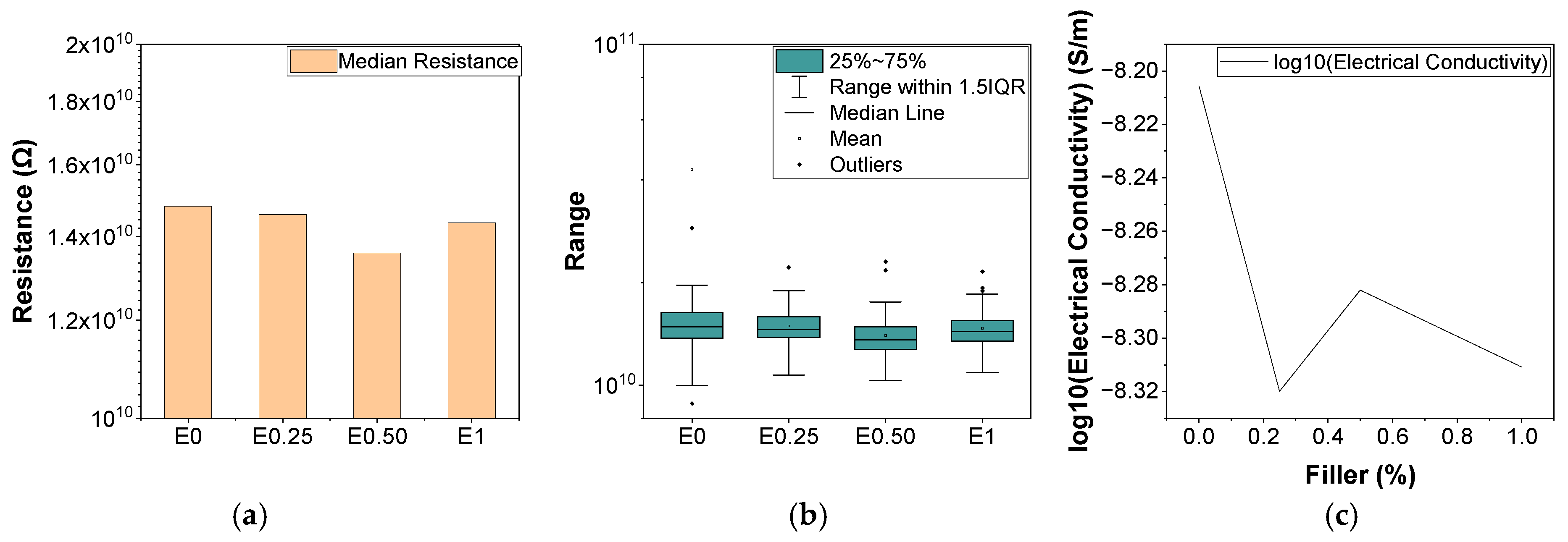
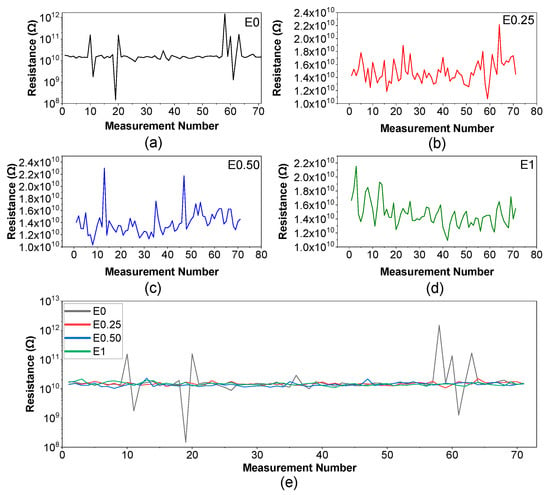
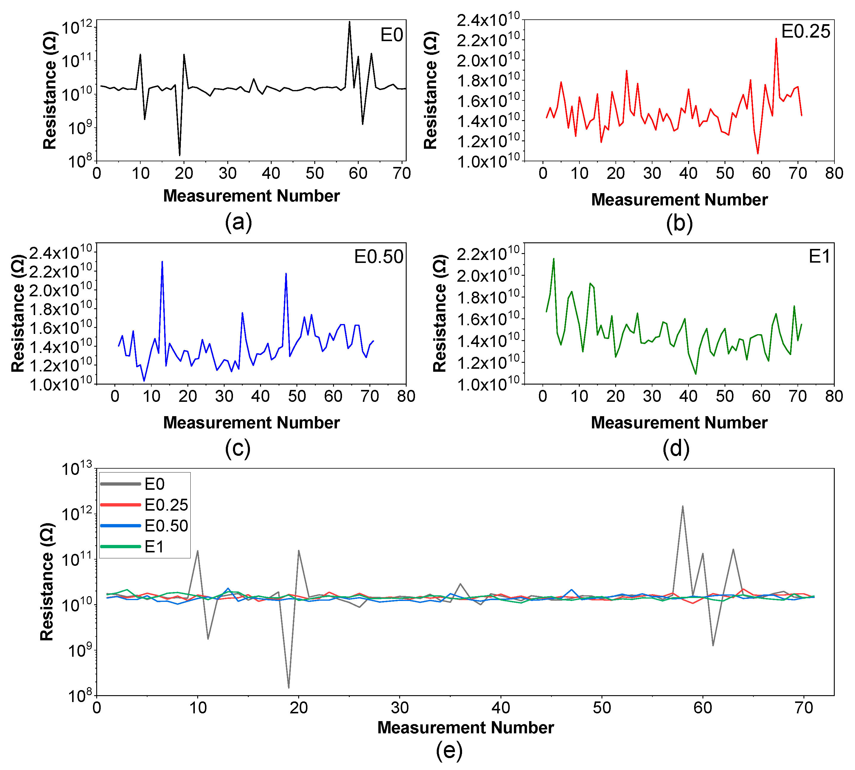
The electrical behavior of the fabricated composites was evaluated using the four-point probe (4PP) method. The measured resistance values were analyzed statistically using median values and box-plot representations to assess measurement repeatability and variability. The corresponding results are summarized in Table 1 and Figure 2, Figure 3 and Figure 4.
Figure 2.
Schematic illustration of localized conductive domain evolution and interfacial polarization behavior with increasing carbon black (CB) loading: (a) E0 (0 wt.% CB), (b) E25 (0.25 wt.% CB), (c) E50 (0.5 wt.% CB), and (d) E1 (1 wt.% CB).
Figure 3.
(a) Median resistance values, (b) box plot distribution of resistance, and (c) logarithmic conductivity as a function of CB content.
Figure 4.
Resistance as a function of measurement number for (a) neat epoxy (E0), (b) 0.25 wt.% CB (E25), (c) 0.5 wt.% CB (E50), and (d) 1 wt.% CB (E1), together with (e) the comparative resistance behavior of all samples.
The median resistance values ranged from 1.36 × 10¹⁰ Ω to 1.48 × 10¹⁰ Ω, with only minor differences among the investigated formulations (Table 1 and Figure 3a). Although the E50 sample exhibited a slightly lower median resistance, the substantial overlap of the interquartile ranges shown in Figure 3b indicates that carbon black incorporation up to 1 wt.% did not significantly modify the bulk electrical response of the composites.
The electrical conductivity values, calculated by considering the measured laminate thickness, varied between 4.79 × 10⁻⁹ and 6.23 × 10⁻⁹ S/m (Table 1). All formulations remained within the same order of magnitude, indicating that the investigated carbon black concentrations were insufficient to induce an electrical percolation transition. The absence of an abrupt conductivity increase further confirms that a continuous conductive network was not established within the composite structure. This observation is consistent with classical percolation theory, which predicts a sharp increase in conductivity only after the formation of an interconnected conductive pathway [11,12].
The logarithmic conductivity variation as a function of CB content is presented in Figure 3c. No systematic conductivity enhancement was observed with increasing filler concentration. The slightly higher conductivity calculated for the E0 sample is associated primarily with thickness normalization effects rather than intrinsic differences in electrical behavior. Consequently, all investigated formulations retained their electrically insulating character despite the incorporation of conductive carbonaceous fillers.
In addition to the average electrical properties, measurement stability was evaluated through repeated 4PP measurements. The resistance fluctuations recorded for individual samples are presented in Figure 4a–d, while the comparative behavior is summarized in Figure 4e. The E0 sample exhibited larger resistance fluctuations than the CB-containing formulations. In contrast, the E25, E50, and E1 composites showed comparatively more stable resistance responses with reduced fluctuation amplitudes. Although all formulations remained within the insulating regime, the incorporation of carbon black appears to improve the uniformity of the electrical response, possibly due to a more homogeneous distribution of carbonaceous regions within the composite structure.
The electrical conductivity results demonstrate that the developed composites remained below the electrical percolation threshold throughout the investigated filler range. Therefore, the EMI shielding behavior discussed in subsequent sections cannot be attributed solely to bulk electrical conductivity. Instead, the results support the interpretation that electromagnetic attenuation is governed primarily by dielectric-loss-related mechanisms associated with heterogeneous interfaces, localized carbon-rich regions, and hierarchical composite architecture.
3.3. Morphological Analysis
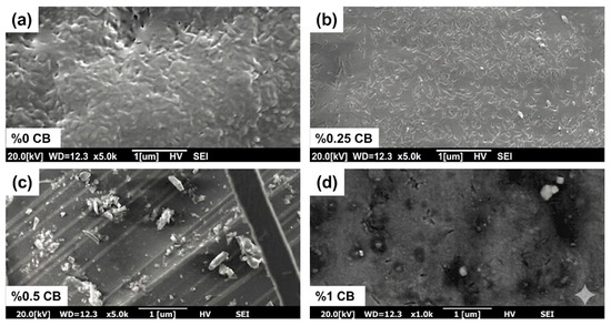
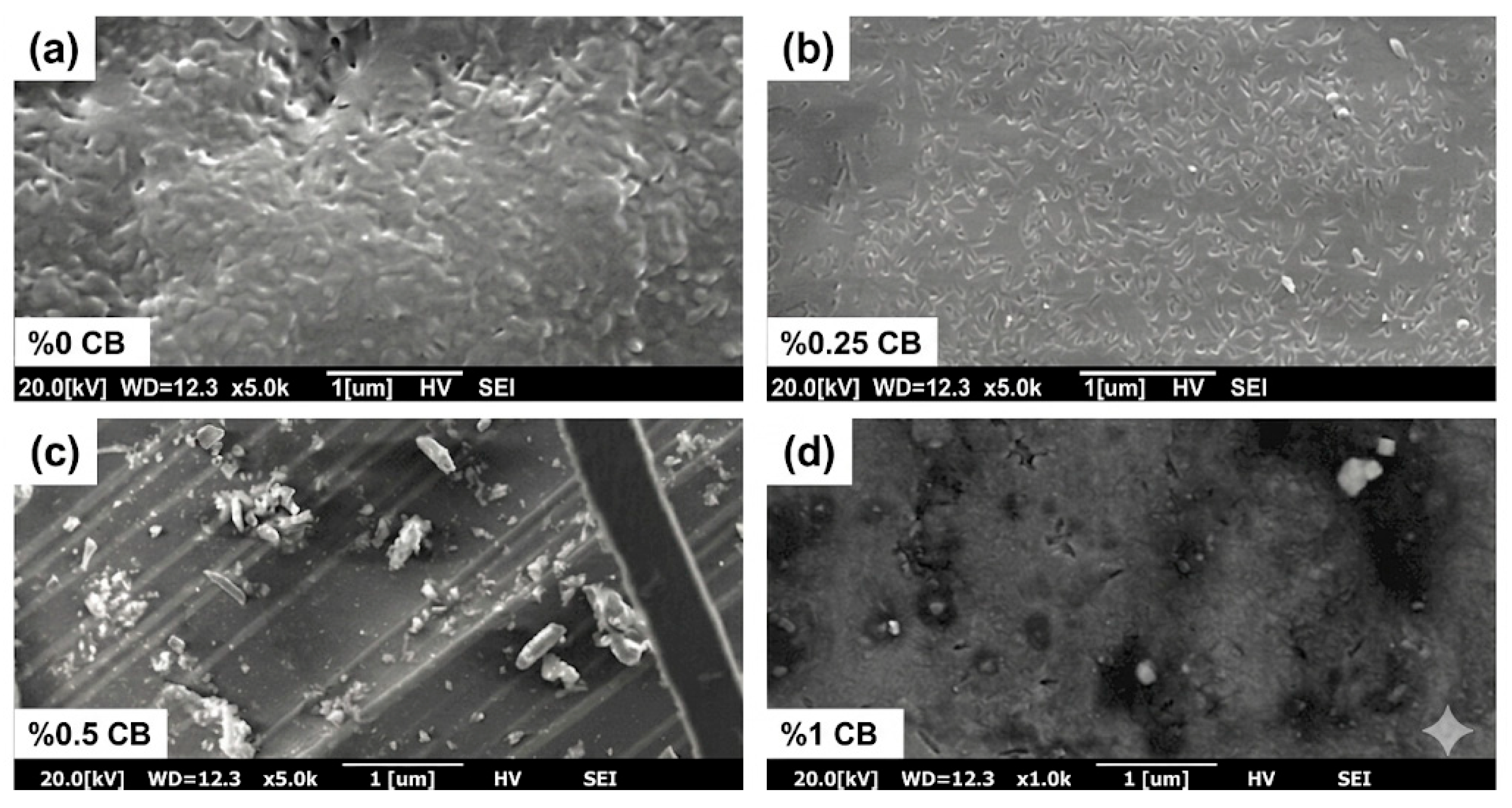
The morphological characteristics of composites containing different carbon black (CB) loadings were investigated by scanning electron microscopy (SEM) to evaluate filler dispersion, agglomeration behavior, and microstructural evolution. Representative SEM micrographs are presented in Figure 5.
Figure 5.
Representative SEM micrographs of epoxy-carbon black composites showing overall microstructural variations across different CB loadings: (a) neat epoxy, (b) 0.25 wt.% CB, (c) 0.5 wt.% CB, and (d) 1 wt.% CB.
The E0 composite (Figure 5a) exhibited a relatively homogeneous morphology dominated by the epoxy matrix and glass fiber reinforcement. No carbon-rich regions were observed, resulting in a comparatively uniform microstructure. Minor surface irregularities are attributed to sample preparation and curing-related effects.
Following the incorporation of 0.25 wt.% CB (E25, Figure 5b), the filler particles appeared to be distributed more uniformly throughout the matrix, with minimal evidence of agglomeration. The relatively homogeneous dispersion increases the effective interfacial area between the carbonaceous filler phase and the insulating polymer matrix. Such heterogeneous interfaces are favorable for polarization-related electromagnetic attenuation mechanisms.
As the CB loading increased to 0.5 wt.% (E50, Figure 5c), localized particle clusters became visible, indicating the onset of agglomeration. A further increase to 1 wt.% CB (E1, Figure 5d) resulted in more pronounced agglomerated regions and a less uniform filler distribution. Representative agglomerated areas are indicated in the revised SEM micrographs. The formation of these clusters reduces the effective interfacial area available for polarization processes and increases microstructural heterogeneity within the composite.
The observed microstructural evolution suggests that the improved EMI shielding response of the E25 composite is associated with a favorable balance between filler dispersion and interfacial area. In contrast, increasing CB content beyond this level promotes agglomeration and reduces the uniformity of the carbonaceous phase distribution. These observations are consistent with the electrical conductivity results, which showed that all formulations remained below the electrical percolation threshold despite the presence of carbon-based fillers.
The SEM observations further support the XRD results, which indicated the coexistence of an amorphous polymer matrix and dispersed carbonaceous regions rather than a highly ordered or continuous graphitic structure. From an EMI shielding perspective, the developed composites can therefore be interpreted as heterogeneous dielectric systems in which attenuation is promoted primarily by interfacial interactions and absorption-related mechanisms rather than by the formation of a continuous conductive network.
3.4. FTIR Results and Discussion
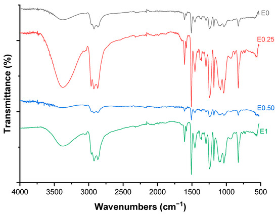
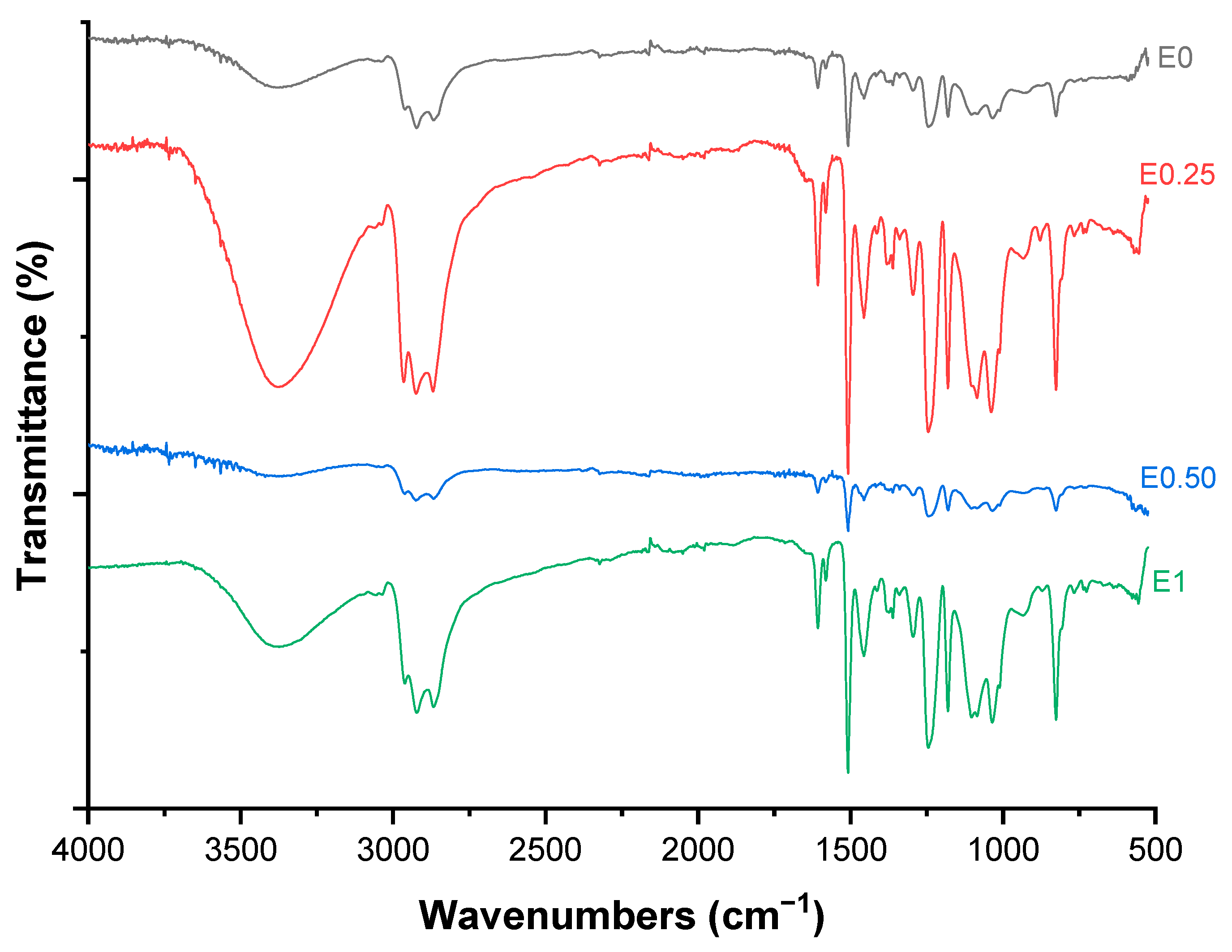
The FTIR spectra of neat epoxy and carbon black (CB)-reinforced composites are presented in Figure 6. All spectra exhibit the characteristic absorption bands of a cured epoxy system, indicating that the fundamental chemical structure of the matrix is preserved after CB incorporation.
Figure 6.
FTIR spectra of neat epoxy and CB-reinforced composites with varying CB contents.
A broad absorption band observed in the range of approximately 3370–3390 cm−1 is attributed to O–H stretching vibrations associated with hydroxyl groups generated during epoxy curing. Aromatic C–H stretching vibrations are observed in the region of 3060–3030 cm−1, while the bands near 2960, 2920, and 2865 cm−1 correspond to aliphatic C–H stretching vibrations of CH2 and CH3 groups. The aromatic C=C stretching vibrations are identified by the characteristic peaks near 1607, 1580, and 1507 cm−1.
The fingerprint region contains the typical absorption bands of cured epoxy systems. Peaks located at approximately 1450–1420 cm−1 are associated with C–H bending vibrations, while the band near 1360 cm−1 corresponds to CH3 deformation. The absorption bands observed around 1295 cm−1, 1245 cm−1, 1180 cm−1, 1100 cm−1, and 1030 cm−1 are attributed to C–O and C–O–C stretching vibrations associated with ether linkages formed during curing [29,30].
No new absorption bands or significant peak shifts were observed following CB incorporation. This indicates that the carbon black acts primarily as a physically dispersed filler and does not introduce detectable changes to the chemical structure of the epoxy network within the investigated concentration range. The characteristic epoxy-related absorption bands remain present in all formulations, suggesting that the curing process was not adversely affected by filler addition.
Minor variations in relative peak intensity were observed among the investigated formulations. However, these changes are insufficient to indicate the formation of new chemical bonds or reaction products. Overall, the FTIR results demonstrate that the structural evolution of the composites is governed primarily by physical dispersion of carbonaceous fillers within the polymer matrix rather than by chemical modification of the epoxy network. These observations are consistent with the XRD and electrical conductivity results, which likewise indicate the absence of significant structural transformations following carbon black incorporation.
3.5. Dynamic Mechanical Analysis (DMA) Results
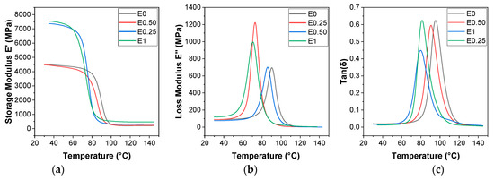
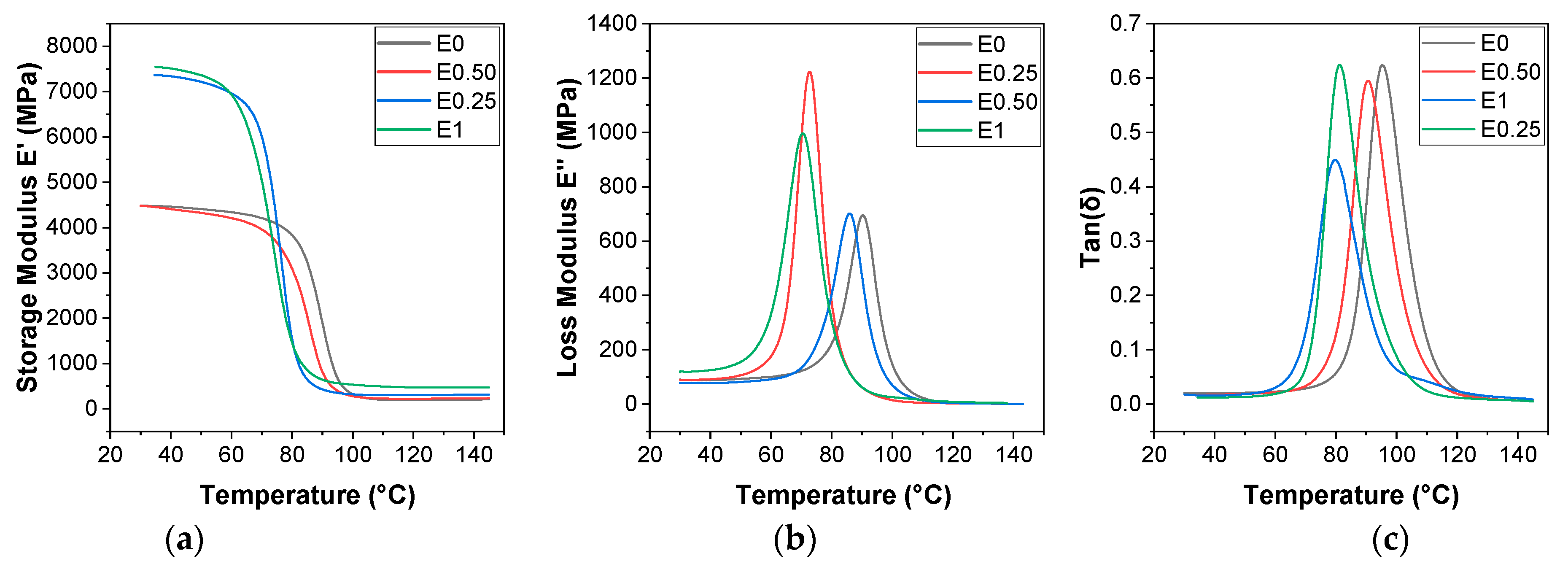
Dynamic mechanical analysis (DMA) was performed to evaluate the viscoelastic behavior of the composites containing different carbon black (CB) loadings. The storage modulus (E′), loss modulus (E″), and loss factor (tan δ) as a function of temperature are presented in Figure 7.
Figure 7.
(a) DMA storage modulus (E′) versus temperature, (b) DMA loss modulus (E″) versus temperature, (c) DMA tan δ versus temperature of epoxy composites with varying CB content (0–1 wt.%).
The storage modulus curves (Figure 7a) exhibit the characteristic behavior of thermoset epoxy systems, with a high modulus in the glassy region followed by a pronounced decrease through the glass transition region and a lower modulus plateau in the rubbery region [31,32]. The neat epoxy exhibited a storage modulus of approximately 4400 MPa in the glassy state. Incorporation of 0.25 wt.% CB resulted in a substantial increase in stiffness, with the storage modulus reaching approximately 7300 MPa. This improvement can be attributed to effective filler dispersion and enhanced stress transfer between the carbonaceous filler phase and the surrounding polymer matrix [7,9,33,34].
For the E50 formulation, a reduction in storage modulus was observed relative to E25, which is consistent with the SEM observations indicating the onset of filler agglomeration. At 1 wt.% CB, the storage modulus increased again, suggesting that the higher filler content contributes to mechanical reinforcement despite the presence of localized agglomerated regions. In the rubbery region, all CB-containing formulations exhibited higher modulus values than the neat epoxy, indicating restricted segmental mobility at elevated temperatures.
The loss modulus (E″) curves shown in Figure 7b provide information regarding molecular relaxation processes within the composite structure. The neat epoxy exhibited a relaxation peak near 90–95 °C. Following CB incorporation, a moderate shift of the peak toward lower temperatures was observed, suggesting changes in polymer chain mobility associated with the presence of dispersed filler particles. The E50 sample exhibited a broader relaxation peak, indicating a wider distribution of local microenvironments and relaxation processes within the composite.
The tan δ curves (Figure 7c) exhibited similar trends. The neat epoxy displayed the highest glass transition temperature (Tg), while the CB-containing composites showed slightly lower Tg values. These observations indicate that the incorporation of carbon black influences the relaxation behavior of the epoxy network through physical filler–matrix interactions rather than through significant chemical modification of the polymer structure.
Variations in tan δ peak intensity further suggest differences in damping behavior among the investigated formulations. The observed changes are consistent with variations in filler dispersion quality, interfacial interactions, and microstructural heterogeneity. Overall, the DMA results demonstrate that carbon black incorporation affects both stiffness and relaxation behavior, with the balance between dispersion quality and agglomeration playing a key role in determining the viscoelastic response of the composites. These findings are consistent with the SEM observations and support the interpretation that composite performance is governed primarily by physical microstructural effects rather than by the formation of a continuous conductive network.
3.6. EMI Shielding Mechanism and Frequency-Dependent Behavior
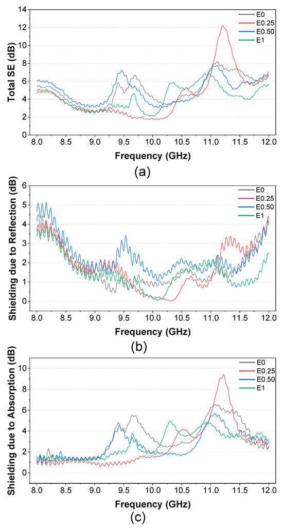
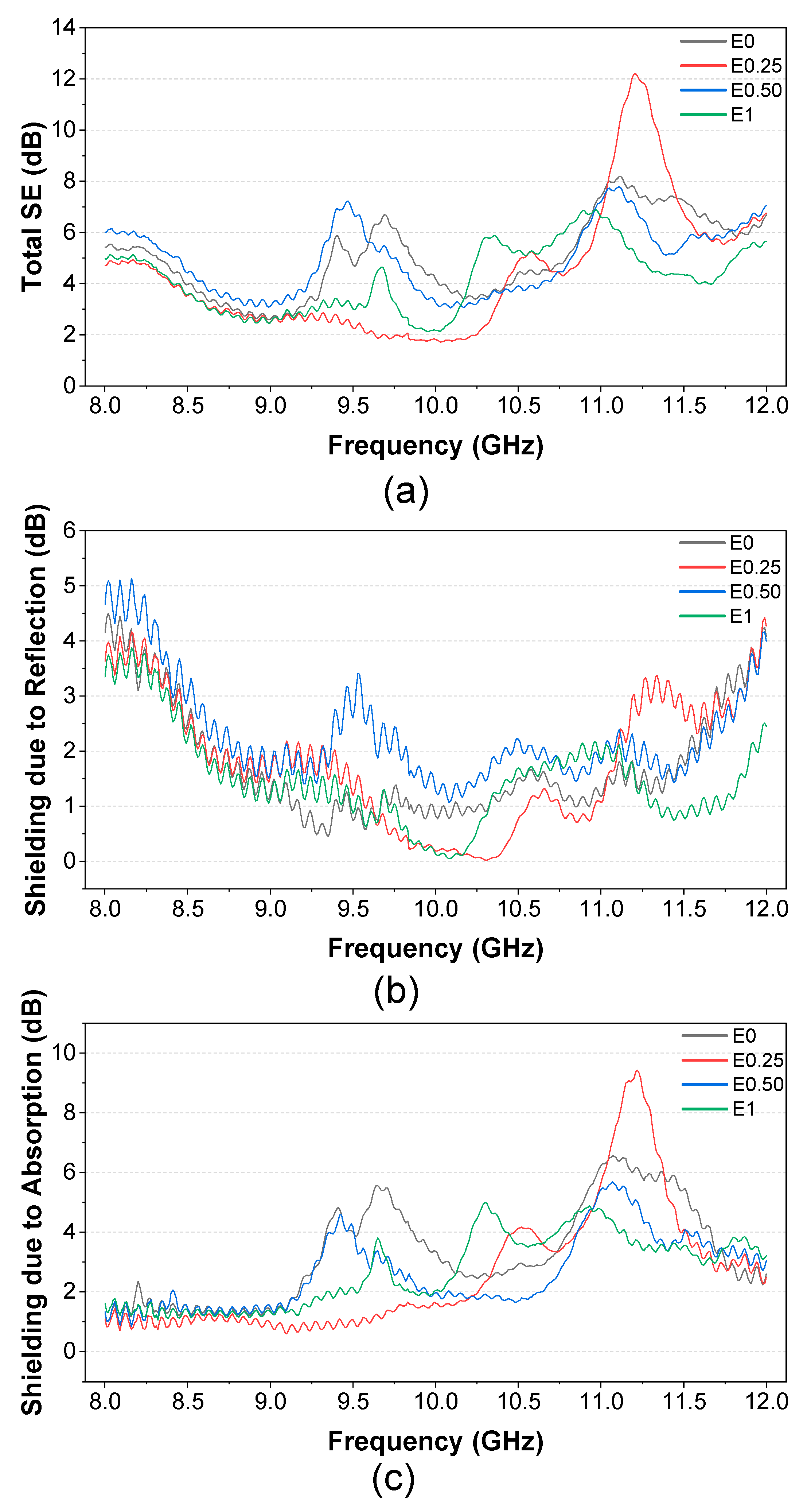
The electromagnetic interference (EMI) shielding performance of the fabricated composites was evaluated within the X-band frequency range (8–12 GHz). The calculated shielding effectiveness components (SEA and SER) together with the total shielding effectiveness (SET) are presented in Figure 8. For all investigated formulations, the shielding response was dominated by absorption rather than reflection. The SEA values consistently exceeded the corresponding SER values throughout the investigated frequency range, indicating that electromagnetic attenuation occurred primarily through internal energy dissipation mechanisms. This behavior is characteristic of electrically insulating polymer composites in which dielectric-loss-related processes contribute more significantly than reflection-based shielding [2,3,7,35]. To further evaluate the attenuation behavior, the reflected (R), transmitted (T), and absorbed (A) power fractions were determined from the measured S-parameters. Analysis of these coefficients confirmed that the observed shielding effectiveness was associated predominantly with attenuation of transmitted electromagnetic energy rather than increased surface reflection. These observations are consistent with the electrical conductivity results, which demonstrated that all formulations remained below the electrical percolation threshold.
Figure 8.
(a) Total shielding effectiveness (SET), (b) shielding effectiveness due to reflection (SER), and (c) shielding effectiveness due to absorption (SEA) as a function of frequency (8–12 GHz) for epoxy composites with varying CB content.
Among the investigated formulations, the E25 composite exhibited the highest peak shielding effectiveness, reaching 12.21 dB at 11.21 GHz. At this frequency, the absorption contribution (SEA = 9.36 dB) was substantially higher than the reflection contribution (SER = 2.85 dB), corresponding to an absorption contribution of approximately 76.6%. This confirms that the peak shielding response of E25 originates primarily from absorption-related attenuation rather than surface reflection, as supported by the higher SEA contribution shown in Figure 8c and the total SET response shown in Figure 8a. The enhanced performance of this formulation is attributed primarily to its favorable filler dispersion and the resulting increase in heterogeneous interfaces within the composite structure. SEM observations showed that E25 exhibited a more uniform carbon black distribution than the higher-loading formulations, while electrical measurements confirmed that the composite remained electrically insulating. Consequently, the improved shielding response is associated with enhanced dielectric attenuation rather than the formation of a continuous conductive network.
Increasing the carbon black content beyond 0.25 wt.% did not produce a proportional improvement in shielding performance. In the E50 and E1 composites, SEM analysis revealed the presence of localized agglomerated regions, which reduce filler dispersion quality and decrease the effective interfacial area available for polarization processes. These observations suggest that filler dispersion plays a more significant role than filler concentration within the investigated loading range.
The relatively low SER values observed across the frequency range indicate improved impedance matching between the composite surface and free space. Reduced reflection allows a greater fraction of the incident electromagnetic energy to penetrate the composite structure, where attenuation occurs through absorption-related mechanisms [36]. In addition, the multilayer architecture formed by graphene-coated glass fiber fabrics promotes multiple internal reflections, increasing the effective propagation path length of electromagnetic waves within the composite.
Frequency-dependent maxima observed near approximately 9.5 GHz and 11–11.5 GHz suggest the presence of resonance-related attenuation phenomena. Such behavior may be associated with dipolar relaxation and Maxwell–Wagner–Sillars (MWS) interfacial polarization processes, both of which are strongly dependent on frequency [19,20]. The hierarchical architecture produced by graphene-coated fibers and dispersed carbonaceous fillers provides numerous heterogeneous interfaces that facilitate these polarization mechanisms.
Overall, the EMI shielding behavior of the developed composites is governed primarily by dielectric-loss-related attenuation mechanisms rather than bulk electrical conduction. The combined effects of dipolar polarization, interfacial polarization, localized charge displacement, and multiple internal reflections contribute to electromagnetic wave attenuation while preserving the electrically insulating character of the composite system. Consequently, the observed shielding performance can be interpreted as a non-percolative and absorption-dominated attenuation process.
3.7. Comparison with Previously Reported EMI Shielding Composites
To better position the present results within the existing literature, the EMI shielding performance of the developed composites was compared with representative carbon-based epoxy composite systems reported previously (Table 2). Most reported graphene-, CNT-, and hybrid carbon-based composites achieve EMI shielding through the formation of electrically conductive networks operating above the percolation threshold [7,14,15,18,20,25,29,37]. Similar behavior has also been reported for epoxy-based composites reinforced with graphene-derived conductive coatings, where improved EMI shielding performance was achieved through interfacial engineering and carbonaceous conductive pathways [30]. In such systems, electrical conductivity typically ranges from 10−4 to 101 S/m, and shielding effectiveness is largely associated with conduction loss and absorption.
Table 2.
Comparison of electrical conductivity, EMI shielding effectiveness, and percolation behavior of representative carbon-based polymer composites reported in the literature.
In contrast, the composites developed in this study remained electrically insulating, exhibiting conductivity values on the order of 10−9 S/m. Despite the absence of electrical percolation, a maximum shielding effectiveness of 12.21 dB was achieved at 11.21 GHz. The results therefore demonstrate that measurable EMI attenuation can be obtained through absorption-dominated dielectric-loss mechanisms, heterogeneous interfaces, and hierarchical composite architecture without relying on high bulk electrical conductivity. This behavior distinguishes the present system from conventional conductivity-driven EMI shielding composites [39] and highlights the potential of non-percolative composite designs for lightweight structural EMI shielding applications.
4. Conclusions
Graphene-coated glass fiber-reinforced epoxy composites containing low carbon black (CB) loadings (0–1 wt.%) were successfully fabricated and evaluated for electromagnetic interference (EMI) shielding applications in the X-band frequency range. Electrical conductivity measurements confirmed that all formulations remained within the electrically insulating regime and did not reach the electrical percolation threshold.
Among the investigated formulations, the composite containing 0.25 wt.% CB exhibited the highest shielding effectiveness, reaching approximately 12 dB near 11.2 GHz. SEM observations revealed that this behavior was associated with improved filler dispersion and increased interfacial areas, whereas higher CB content promoted agglomeration and reduced shielding efficiency. XRD, FTIR, and DMA analyses further demonstrated that CB incorporation primarily influenced the composite through physical microstructural effects, including changes in dispersion and stiffness, without introducing significant chemical modifications to the epoxy network.
Overall, the EMI shielding performance of the developed composites is governed predominantly by absorption-related attenuation mechanisms rather than bulk electrical conduction. The combined effects of interfacial polarization, dipolar relaxation, localized charge displacement, and multiple internal reflections enabled measurable EMI shielding while preserving the electrically insulating character of the material. These findings demonstrate that effective EMI shielding can be achieved without the formation of a continuous conductive network and provide a practical design strategy for lightweight multifunctional composite materials intended for aerospace and advanced electronic applications. The present results demonstrate that effective EMI shielding can be achieved without electrical percolation, highlighting interfacial engineering and hierarchical composite design as viable alternatives to conventional conductivity-driven shielding approaches.
Author Contributions
M.Y. (Muhammed Yilmaz): visualization, investigation, writing—original draft preparation, methodology, resources. M.Y. (Metin Yurddaskal): supervision, writing—reviewing and editing. All authors have read and agreed to the published version of the manuscript.
Funding
This research received no external funding.
Data Availability Statement
The raw data supporting the conclusions of this article will be made available by the authors on request.
Acknowledgments
This work was supported by the infrastructural facilities of Dokuz Eylul University, Center for Production and Applications of Electronic Materials (EMUM). During the preparation of this manuscript, the authors used ChatGPT (OpenAI, GPT-5.5) for language editing, improving clarity, and refining readability. The authors reviewed and edited all outputs and took full responsibility for the content of this publication.
Conflicts of Interest
The authors declare no conflicts of interest.
References
- Geetha, S.; Kumar, K.K.S.; Rao, C.R.K.; Vijayan, M.; Trivedi, D.C. EMI shielding: Methods and materials—A review. J. Appl. Polym. Sci. 2009, 112, 2073–2086. [Google Scholar] [CrossRef] [Scilit]
- Chung, D.D.L. Electromagnetic interference shielding effectiveness of carbon materials. Carbon 2001, 39, 279–285. [Google Scholar] [CrossRef] [Scilit]
- Shahzad, F.; Alhabeb, M.; Hatter, C.B.; Anasori, B.; Hong, S.M.; Koo, C.M.; Gogotsi, Y. Electromagnetic interference shielding with 2D transition metal carbides (MXenes). Science 2016, 353, 1137–1140. [Google Scholar] [CrossRef] [Scilit] [PubMed]
- Kim, J.K.; Mai, Y.W. Engineered Interfaces in Fiber Reinforced Composites; Elsevier: Amsterdam, The Netherlands, 1998. [Google Scholar]
- Mallick, P.K. Fiber-Reinforced Composites: Materials, Manufacturing, and Design; CRC Press: Boca Raton, FL, USA, 2007. [Google Scholar]
- Friedrich, K.; Fakirov, S.; Zhang, Z. Polymer Composites: From Nano- to Macro-Scale; Springer: Berlin/Heidelberg, Germany, 2005. [Google Scholar]
- Al-Saleh, M.H.; Sundararaj, U. Electromagnetic interference shielding mechanisms of CNT/polymer composites. Carbon 2009, 47, 1738–1746. [Google Scholar] [CrossRef] [Scilit]
- Bauhofer, W.; Kovacs, J.Z. A review and analysis of electrical percolation in carbon nanotube polymer composites. Compos. Sci. Technol. 2009, 69, 1486–1498. [Google Scholar] [CrossRef] [Scilit]
- Kim, H.; Abdala, A.A.; Macosko, C.W. Graphene/polymer nanocomposites. Macromolecules 2010, 43, 6515–6530. [Google Scholar] [CrossRef] [Scilit]
- Spitalsky, Z.; Tasis, D.; Papagelis, K.; Galiotis, C. Carbon nanotube–polymer composites: Chemistry, processing, mechanical and electrical properties. Prog. Polym. Sci. 2010, 35, 357–401. [Google Scholar] [CrossRef] [Scilit]
- Kirkpatrick, S. Percolation and conduction. Rev. Mod. Phys. 1973, 45, 574–588. [Google Scholar] [CrossRef] [Scilit]
- Stauffer, D.; Aharony, A. Introduction to Percolation Theory; Taylor & Francis: London, UK, 1994. [Google Scholar]
- Yang, Y.; Gupta, M.C.; Dudley, K.L.; Lawrence, R.W. Novel carbon nanotube–polystyrene foam composites for electromagnetic interference shielding. Nano Lett. 2005, 5, 2131–2134. [Google Scholar] [CrossRef] [Scilit] [PubMed]
- Shen, B.; Zhai, W.; Zheng, W. Ultralight multifunctional graphene aerogels: A review. Adv. Funct. Mater. 2014, 24, 4542–4553. [Google Scholar]
- Zhang, H.B.; Yan, Q.; Zheng, W.G.; He, Z.; Yu, Z.Z. Tough graphene–polymer microcellular foams for electromagnetic interference shielding. ACS Appl. Mater. Interfaces 2011, 3, 918–924. [Google Scholar] [CrossRef] [Scilit] [PubMed]
- Li, X.; Gao, H.; Chen, G.; Zhang, Y.; Liu, Y. Graphene-coated glass fiber composites with enhanced interfacial properties. Compos. Sci. Technol. 2015, 123, 125–132. [Google Scholar] [CrossRef] [Scilit]
- Rafiee, M.A.; Rafiee, J.; Wang, Z.; Song, H.; Yu, Z.; Koratkar, N. Enhanced mechanical properties of nanocomposites at low graphene content. ACS Nano 2009, 3, 3884–3890. [Google Scholar] [CrossRef] [Scilit] [PubMed]
- Liu, Y.; Zhang, X.; Li, X. Lightweight graphene-based composites for EMI shielding. Carbon 2020, 167, 777–789. [Google Scholar] [CrossRef] [Scilit]
- Chen, Z.; Xu, C.; Ma, C.; Ren, W.; Cheng, H.M. Lightweight and flexible graphene foam composites. Adv. Mater. 2013, 25, 1296–1300. [Google Scholar] [CrossRef] [Scilit] [PubMed]
- Liang, J.; Wang, Y.; Zhang, D. Multiscale conductive networks in polymer composites. Compos. Sci. Technol. 2021, 202, 108596. [Google Scholar] [CrossRef] [Scilit]
- Dang, Z.M.; Yuan, J.K.; Zha, J.W.; Zhou, T.; Li, S.T.; Hu, G.H. Fundamentals, processes and applications of high-permittivity polymer–matrix composites. Prog. Mater. Sci. 2012, 57, 660–723. [Google Scholar] [CrossRef] [Scilit]
- Sillars, R.W. The properties of a dielectric containing semiconducting particles of various shapes. J. Inst. Electr. Eng. 1937, 80, 378–394. [Google Scholar] [CrossRef] [Scilit]
- Cole, K.S.; Cole, R.H. Dispersion and absorption in dielectrics. J. Chem. Phys. 1941, 9, 341–351. [Google Scholar] [CrossRef] [Scilit]
- Jalali, M.; Esmaeili, A. Dielectric-dominated EMI shielding. ACS Appl. Mater. Interfaces 2020, 12, 45012–45023. [Google Scholar] [CrossRef] [Scilit] [PubMed]
- Song, W.L.; Cao, M.S.; Lu, M.M.; Bi, S.; Wang, C.Y.; Liu, J.; Yuan, J. Flexible graphene/polymer composite films in EMI shielding. Adv. Mater. 2012, 24, 2469–2474. [Google Scholar]
- Zeng, Z.; Jin, H.; Chen, M.; Li, W.; Zhou, L.; Zhang, Z. Lightweight and anisotropic EMI shielding materials. Adv. Mater. 2010, 22, 4569–4573. [Google Scholar]
- Van Loock, F.; Ravichandran, P.; Li., X.; Anderson, P.D.; Cardinaels, R. Design of lossy dielectric polymer nanocomposite alternating A–B multilayers for absorption-dominated EMI shielding in the X-band regime. Compos. Part A Appl. Sci. Manuf. 2025, 191, 108715. [Google Scholar] [CrossRef] [Scilit]
- Drakopoulou, N.; Giannakopoulou, T.; Trapalis, C.; Tarantili, P.A. Solution mixing synthesis of epoxy nanocomposites reinforced with MWCNTs and graphene: Thermal stability and EMI shielding effectiveness study. J. Compos. Sci. 2025, 9, 326. [Google Scholar] [CrossRef] [Scilit]
- Antunes, M. Recent Trends in Polymeric Foams and Porous Structures for Electromagnetic Interference Shielding Applications. Polymers 2024, 16, 195. [Google Scholar] [CrossRef] [Scilit] [PubMed]
- Odabaşı, H.K. Electrical, thermal, flexural, and EMI-shielding properties of epoxy-based polymer composites reinforced with RGO/AgRGO spray-coated carbon fibers. Coatings 2025, 15, 1404. [Google Scholar] [CrossRef] [Scilit]
- Coates, J. Interpretation of infrared spectra, a practical approach. In Encyclopedia of Analytical Chemistry; Meyers, R.A., Ed.; Wiley: Chichester, UK, 2000. [Google Scholar] [CrossRef] [Scilit]
- Silverstein, R.M.; Webster, F.X.; Kiemle, D.J. Spectrometric Identification of Organic Compounds, 7th ed.; Wiley: New York, NY, USA, 2005. [Google Scholar]
- Menard, K.P. Dynamic Mechanical Analysis: A Practical Introduction, 2nd ed.; CRC Press: Boca Raton, FL, USA, 2008. [Google Scholar]
- Ferry, J.D. Viscoelastic Properties of Polymers, 3rd ed.; Wiley: New York, NY, USA, 1980. [Google Scholar]
- Sumfleth, J.; Gojny, F.H.; Wichmann, M.H.G.; Fiedler, B.; Schulte, K. A review of the electrical and mechanical properties of carbon nanotube/epoxy composites. Polymer 2010, 51, 3814–3825. [Google Scholar] [CrossRef] [Scilit]
- Gajić, B.; Radoičić, M.; Yasir, M.; Saeed, W.; Bolka, S.; Nardin, B.; Potočnik, J.; Bajuk-Bogdanović, D.; Ćirić-Marjanović, G.; Šaponjić, Z.; et al. Synergistic Integration of Polypyrrole, Graphene Oxide, and Silver Nanowires into Flexible Polymeric Films for EMI Shielding Applications. Molecules 2025, 30, 4221. [Google Scholar] [CrossRef] [Scilit] [PubMed]
- Kim, H.; Park, J.; Hong, J. Enhanced EMI shielding effectiveness of graphene nanoplatelet composites. Carbon 2014, 77, 868–874. [Google Scholar] [CrossRef] [Scilit]
- Reis, R.H.M.; Lima, R.C.; Monteiro, S.N.; Figueiredo, A.B.-H.; Santos, C.L.S.; Nascimento, L.F.C. Ballistic and Electromagnetic Shielding Properties of Epoxy Resin Reinforced with Carbon Black and Jute Fabric. Polymers 2025, 17, 336. [Google Scholar] [CrossRef] [Scilit] [PubMed]
- Jang, D.; Park, J.; Jang, W.; Bang, J.; Kim, G.M.; Choi, J.; Seo, J.; Yang, B. Influence of Conductive Filler Types on the Ratio of Reflection and Absorption Properties in Cement-Based EMI Shielding Composites. Materials 2024, 17, 4913. [Google Scholar] [CrossRef] [Scilit] [PubMed]

Disclaimer/Publisher’s Note: The statements, opinions and data contained in all publications are solely those of the individual author(s) and contributor(s) and not of MDPI and/or the editor(s). MDPI and/or the editor(s) disclaim responsibility for any injury to people or property resulting from any ideas, methods, instructions or products referred to in the content. |
© 2026 by the authors. Licensee MDPI, Basel, Switzerland. This article is an open access article distributed under the terms and conditions of the Creative Commons Attribution (CC BY) license.