


Abstract
Tubing couplings are recognized as a vulnerable link in pipe string integrity, accounting for over 60% of all failure incidents. In this study, a perforation-failed N80 double-male short sub retrieved from a coalbed methane jet pump well was systematically investigated. A multi-faceted analytical approach was adopted, integrating macroscopic morphological examination, scanning electron microscopy (SEM), and X-ray diffraction (XRD) for material characterization, in conjunction with computational fluid dynamics (CFD) numerical simulations based on the Realizable k-ε turbulence model. The objective was to elucidate the causes of corrosion failure and the underlying mechanism of flow-field-induced corrosion acceleration. The results show that the corrosion products on the inner wall of the short sub are mainly composed of FeCO3 and iron oxides, resulting from the synergistic electrochemical corrosion of CO2 and dissolved oxygen. The “J”-shaped groove formed at the junction between the double-male short sub and the adjacent upper and lower couplings introduces a geometric discontinuity that significantly perturbs the local flow field, leading to a binary partitioned flow structure. This structure comprises a high-shear-stress zone at the groove edges, with a peak wall shear stress reaching up to 58.5 Pa, and a vortex-stagnation dead zone at the groove center, where the flow velocity drops to as low as 0.13 m/s. This flow-field structure is the primary cause of local corrosion. High shear stress continuously scours and removes the protective corrosion film, accelerating the corrosion process, while the vortex-stagnation zone facilitates localized enrichment of corrosive species. The synergistic interplay between these two mechanisms ultimately results in localized perforation within the threaded region of the short sub. The results provide theoretical support for optimizing oil pipe coupling structures and suppressing erosion corrosion in oil and gas well pipe strings.
1. Introduction
As oil and gas exploration and development continue to extend into deeper and more complex geological formations, operating conditions for downhole pipe strings have become increasingly demanding, posing significant challenges to pipe-string integrity [1,2]. According to statistics, among all types of pipe column failure incidents, the threaded connection between the pipe column body and the joint is the most critical failure area, accounting for approximately 64% of the failure incidents [2,3]. As a critical component connecting tubing strings, the tubing coupling not only sustains complex composite loads including tension, compression, bending, and internal pressure, but also exhibits a distinct structural configuration that renders it highly susceptible to corrosion-related failures [3,4]. Once the coupling fails, it will directly lead to leakage of the pipe string, a decrease in production volume, and even trigger major safety accidents such as well blowouts, causing huge economic losses and environmental pollution. Therefore, an in-depth investigation of the failure mechanism of tubing couplings is crucial for ensuring the safe and efficient development of oil and gas fields.
The factors contributing to tubing coupling failure are multifaceted and generally attributable to the synergistic effects of three categories: material properties, environmental media, and mechanical loading [5,6,7]. Firstly, research has been conducted on the load-bearing and deformation behavior of threaded connections under applied loads. The threaded connection part inherently has geometric discontinuities, such as wear, clearance and fit errors [2,4,8,9]. Wang analyzed the coupling effect of thread lubricant friction and the engagement position (J value) on the sealing performance. The results showed that the assembly displacement caused by friction, approximately 1 mm (about 0.3 turns), could trigger seal failure by reducing the thread contact pressure, and the critical leakage threshold was determined to be J ≈ 12.3 mm [10]. Li et al. established a failure pressure assessment model based on the nonlinear finite element method, and analyzed the influence of defect shape, size parameters and external loads on the ultimate internal pressure-bearing capacity of CO2 injection tubing [11]. Chen et al. established a finite element simulation model of the 12in tubing joint, and studied the influence of radial load and pitch on the tightening characteristics and torsional-tension relationship of the tubing joint. The results showed that the radial load caused the stress distribution of the tubing joint to change from “central symmetry” to “symmetry along the gravitational direction”, and at the same time, it exacerbated the bearing ratio of the two teeth at the end; the stress distribution of the teeth under different pitch conditions indicated that in this complex environment, the small pitch threads had more advantages in the uniformity of load distribution [12]. The above studies have provided an important basis for understanding the mechanical behavior of threaded connections, but they have mostly focused on static behavior and sealing performance, with relatively little attention paid to the role of the flow environment. Moreover, the corrosive components such as CO2, H2S, Cl− and dissolved O2 in downhole environments constitute a highly aggressive electrochemical corrosion environment [13,14]. Especially when CO2 and O2 coexist, the corrosion behavior of N80 steel becomes more complex, and its corrosion products mainly consist of FeCO3 and iron oxides [15]. The thread’s special structure allows corrosive media such as CO2, H2S, and chloride ions to seep in and remain inside the thread, while the sudden change in the pipe body’s geometry further exacerbates local corrosion. Yang et al. conducted research on the failure behavior and mechanism of oil pipes in CO2-driven production wells. The results indicate that the pipe fracture is caused by stress corrosion cracking triggered by the corrosion of the root of the threads. Corrosive substances accumulated in the thread gaps, leading to local acidification and an increase in the concentrations of Cl− and S2−, thereby inducing local corrosion [3].
In addition, fluid-dynamic effects arising from multiphase flow within the pipe are another crucial factor that cannot be ignored [15,16,17]. After making up API round-thread tubing couplings, a groove of specified width is retained at the center of the coupling, forming a “J”-shaped zone. When the fluid passes through structurally abrupt changes, such as the “J”-shaped area of the coupling, the sudden change in flow area triggers flow the reformation, generating local vortices, high wall shear stress and intense pressure fluctuations. This flow field change significantly accelerates the mass transfer process between the corrosive medium and the pipe wall and hinders the formation of a stable protective corrosion product layer, thereby inducing severe erosion-corrosion [18,19]. In the high-pressure and atmospheric pressure condenser for ammonia recovery, the 316L stainless steel tube experienced thinning of the inner wall at the inlet end due to erosion corrosion. This tube was also affected by stress corrosion cracking and crevice corrosion, and eventually failed and leaked due to SCC penetrating the wall thickness [20]. Under multiphase flow containing sand, abrupt structural changes such as a four-way valve/stop valve (or pipe joint) can cause erosion corrosion failure of 316L stainless steel (or super 13Cr stainless steel) due to high-speed fluid impact induced by vortices [6]. Malka et al. focused on AISI 1018 carbon steel and investigated in a real flow environment featuring sudden changes in pipe diameter, expansion, and protrusions. They explored the interaction between erosion and corrosion and quantified their synergistic effect. The results indicated that erosion and corrosion mutually promoted each other, with a significant synergistic effect. Among them, the enhancing effect of corrosion on erosion was the dominant mechanism [21]. Gu et al., through large-scale field surveys, systematic fluid analysis, and downhole coupon tests, identified the high salinity (7278.66–18,922.74 mg/L) and high CO2 partial pressure (0.16–0.99 MPa) of the produced water as the core environmental factors driving electrochemical corrosion, and as important causes of tubing string failure [22]. Under high Cl− conditions, Cl− disrupts the integrity of the FeCO3 protective film through a “competitive adsorption-chemical dissolution” mechanism, thereby inducing pitting corrosion. This study also employed grey relational analysis to preliminarily evaluate the relative importance of various factors, among which the contributions of flow-field shear stress (relational degree 0.89) and Cl− concentration (relational degree 0.83) were relatively prominent. However, the flow regime within the wellbore was not further analyzed.
According to the existing research, research on pipe coupling failure mainly focuses on static mechanics and sealing performance. For instance, the influence of upper-threading torque, axial load and bending load on the connection strength and sealing performance is analyzed, and corresponding theoretical models and numerical simulation methods are established [1,9]. However, studies on the impact of local flow field changes caused by structural abrupt changes at the coupling joint on its failure are relatively scarce. Existing research often considers corrosion and fluid mechanics separately, making it difficult to comprehensively reveal the intrinsic laws governing the accelerated evolution of local corrosion at the joint connection under complex flow fields.
This work focuses on an N80 steel tubing double-male crossover sub that failed due to experienced corrosion perforation in a coalbed methane well. A comprehensive approach integrating macroscopic and microscopic morphological observations, corrosion product phase analysis, and computational fluid dynamics (CFD)-based numerical simulations was employed to systematically investigate the flow-field reconfiguration patterns induced by the structural discontinuity of the coupling “J” region, and to elucidate the erosion–corrosion mechanism governed by the synergistic action of high shear stress and vortex stagnation. The findings of this research are expected to provide a scientific theoretical basis for the failure prevention and structural optimization design of tubing couplings.
2. Materials and Methods
2.1. Failure Information and Working Condition Background
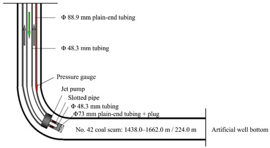
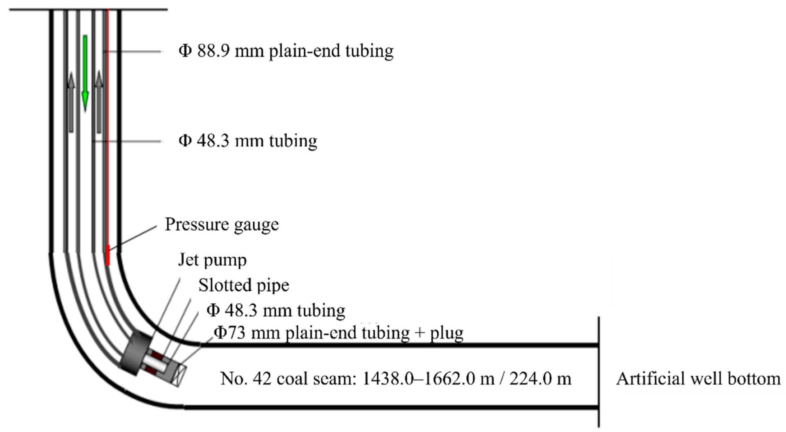
A coalbed methane production well was commissioned in May 2024, employing jet pump technology for gas extraction, with a total completed depth of 1691.00 m. Figure 1 illustrates the well completion string and borehole configuration. The tubing and center pipe are made of N80 steel. The wellbore structure of this well is centered on the central pipe—oil pipe annulus configuration, and the variable coupling short section is located near the central pipe coupling. The bottom hole temperature was approximately 35.9 °C. The produced fluid was liquid, with a mineralization degree of 11,778–13,295 mg/L, hardness of 170.64–346.78 mg/L, and a pH ranging from 7.7 to 8.2, with minor amounts of SiO2 solid particles. The coal seam water type is a weakly alkaline NaHCO3 type. The cations in the produced liquid were K+, Na+, Ca2+, Mg2+, NH4+, and the main anions were Cl−, SO42−, HCO3−, NO3−. Table 1 presents detailed ion concentrations. The gas components of the coal seam exhibit typical characteristics of low-rank coal seams, with methane as the main component, followed by carbon dioxide, and other gases accounting for a smaller proportion. In the No. 39 coal seam, CO2 content ranges from 6.48% to 23.89%, averaging 10.83%, with most values concentrated between 6% and 12%. For the No. 41 coal seam, the CO2 content varies between 6.48% and 27.95%, averaging 18.69%. In the No. 42 coal seam, CO2 content ranges from 10.04% to 25.37%, with a mean value of 20.15%.
Figure 1.
Well completion string and borehole configuration.
Table 1.
Composition of produced fluid.
2.2. Material Characterization Methods
The phase composition of the corrosion product film on the double-male crossover sub was characterized by X-ray diffraction (XRD, D8 Advance, Bruker, Karlsruhe, Germany) over a 2θ scanning range of 10° to 90° at a scanning rate of 10°/min. The microscopic corrosion morphology of the double-male crossover sub was examined using scanning electron microscopy (SEM, SU-70, Hitachi, Tokyo, Japan), and the elemental composition of the corrosion products was analyzed by means of the attached energy-dispersive X-ray spectroscopy (EDS) system.
2.3. Numerical Simulation Analysis
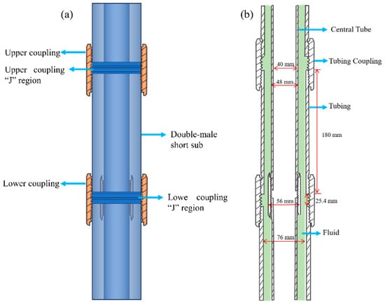
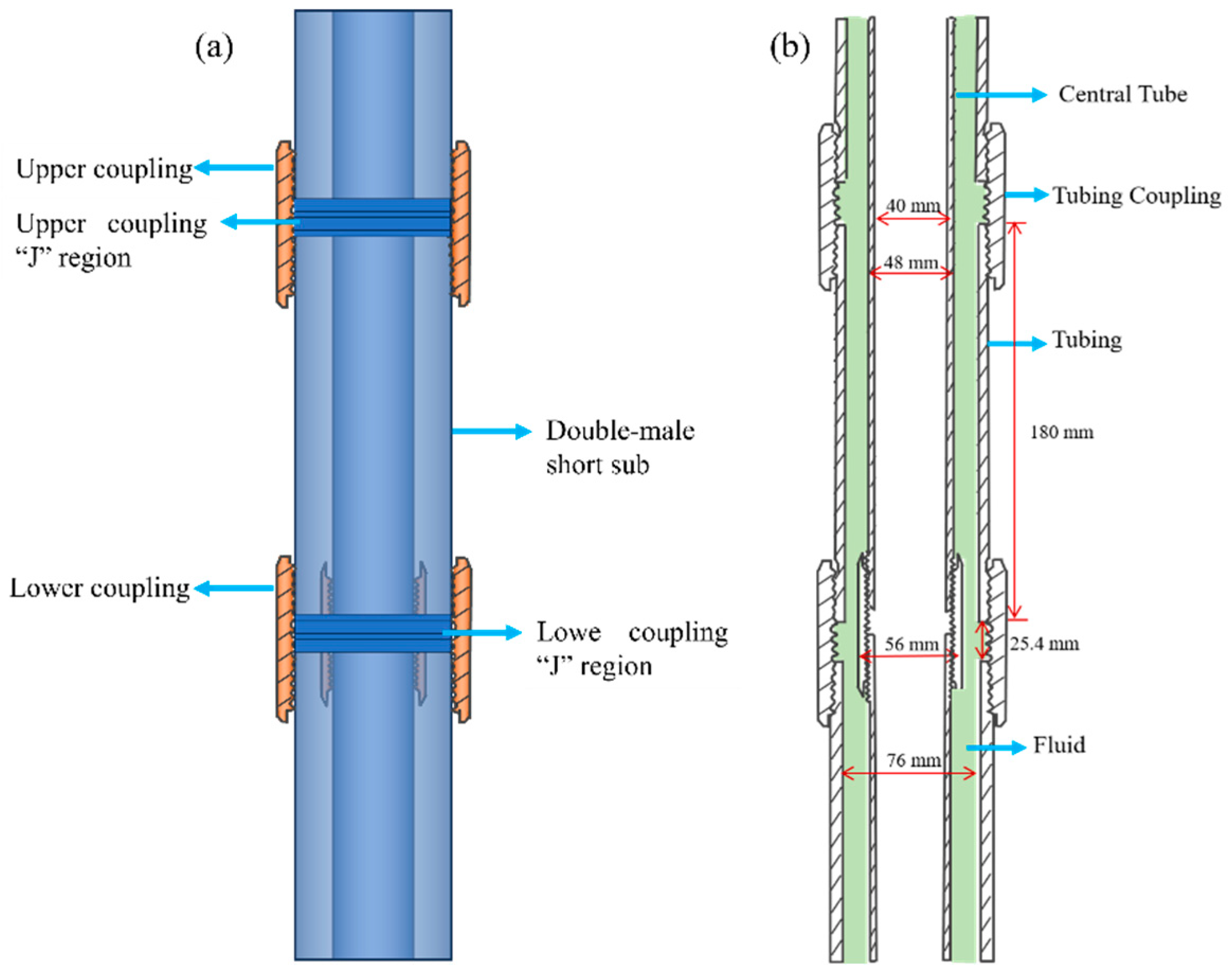
The corrosion process under flowing conditions is closely governed by flow-related parameters. To investigate the flow-field variations induced by surface depressions, numerical simulations were performed using computational fluid dynamics (CFD) software to obtain detailed near-wall flow-field characteristics in the presence of surface defect pits. A three-dimensional model of the annulus between the central pipe and the tubing was established based on the actual dimensions of the test section, as depicted in Figure 2. The central pipe has an outer diameter of 48 mm and an inner diameter of 40 mm, while the tubing has an outer diameter of 88.9 mm and an inner diameter of 76 mm. The double-male crossover sub corresponds to a Φ73 mm plain-end to Φ73 mm upset double-male crossover sub.
Figure 2.
(a) Schematic diagram of tubing coupling connection, (b) tubing string dimensions.
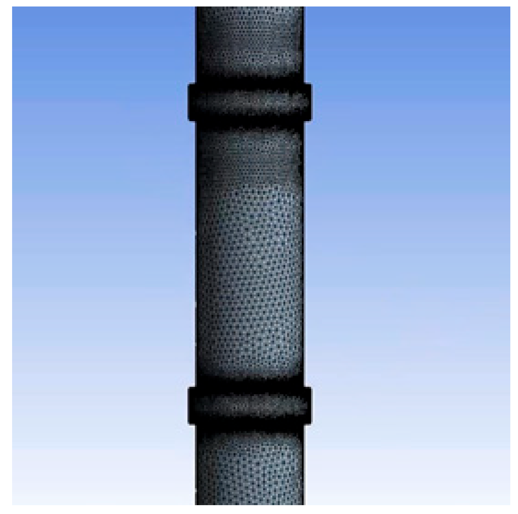
The standard k-ε turbulence model was used to numerically solve the flow process, assuming the fluid is incompressible. The boundary conditions were configured as follows: a velocity inlet was adopted, with the inlet flow velocity calculated as 2.212 m/s based on the produced fluid rate, under which the flow-field analysis was conducted. Because the distance from the coupling to the outlet exceeds 30 times the hydraulic diameter, the outlet flow was considered fully developed, and an outflow boundary condition was specified at the outlet. To balance computational accuracy and efficiency, a mesh system consisting of 3,893,234 elements was ultimately adopted, with the meshing scheme illustrated in Figure 3. The walls were set as stationary no-slip wall boundaries.
Figure 3.
Mesh generation scheme of the computational domain.
3. Results and Discussion
3.1. Macroscopic Corrosion Morphology Analysis
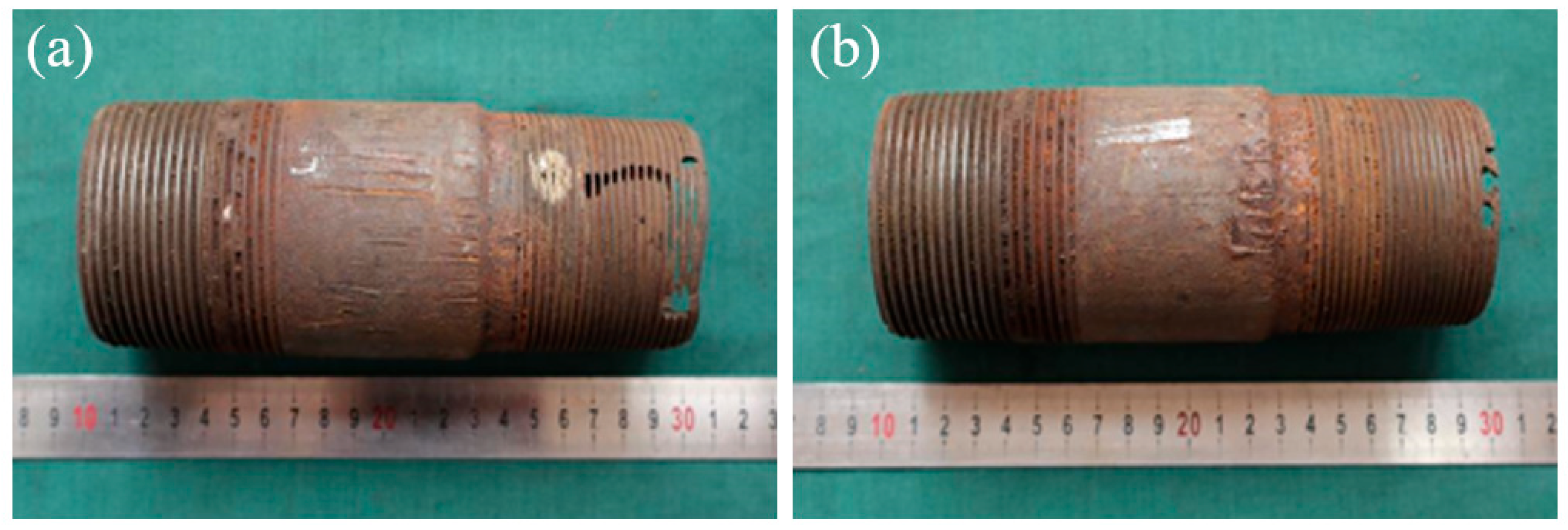
During workover operations, a Φ73 mm plain-end to Φ73 mm upset double-male crossover sub located at a depth of 1220.03–1220.15 m, was found to be severely corroded. Figure 4 presents the macroscopic morphology of its outer wall. As shown in the figure, the upset end is on the left side, and the plain end is on the right side. Corrosion damage is predominantly concentrated in the plain-end pin-threaded region, where extensive perforation and structural deformation are widely observed on the external threads. In contrast, the upset-end pin threads exhibit only mild corrosion, with the thread profile remaining relatively intact. No obvious signs of corrosion are visible on the outer wall of the central pipe section between the two pin ends. It is preliminarily inferred that the corrosion perforation of this crossover sub propagated from the inner wall to the outer wall.
Figure 4.
Macroscopic morphology of the outer wall of the double-male crossover sub: (a) 0°, (b) 180°.
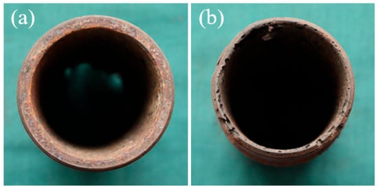
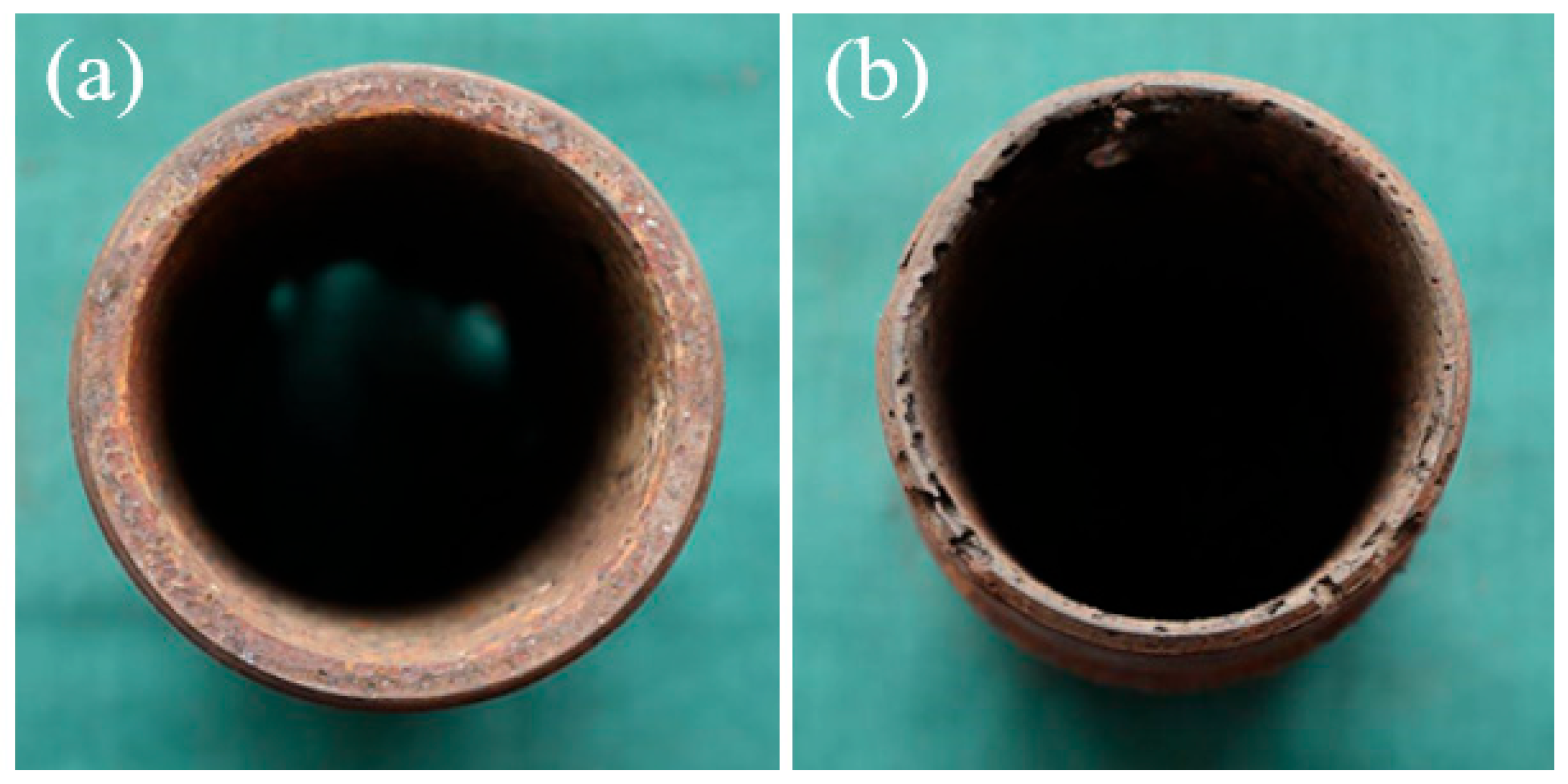
Figure 5 shows the macroscopic morphology of the end faces of the double-male crossover sub. The upset end face is relatively flat, with minor variations in inner and outer diameters, and no significant wall-thickness reduction is evident; the measured minimum remaining wall thickness is 5.64 mm. In contrast, the plain end face is uneven and irregular, with wall-thickness reduction in areas without perforation already falling below 0.81 mm.
Figure 5.
Macroscopic surface morphology of the short section end of the double-male crossover sub: (a) thickened end face, (b) flat end face.
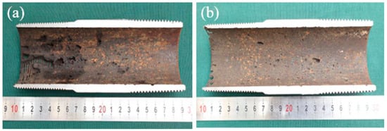
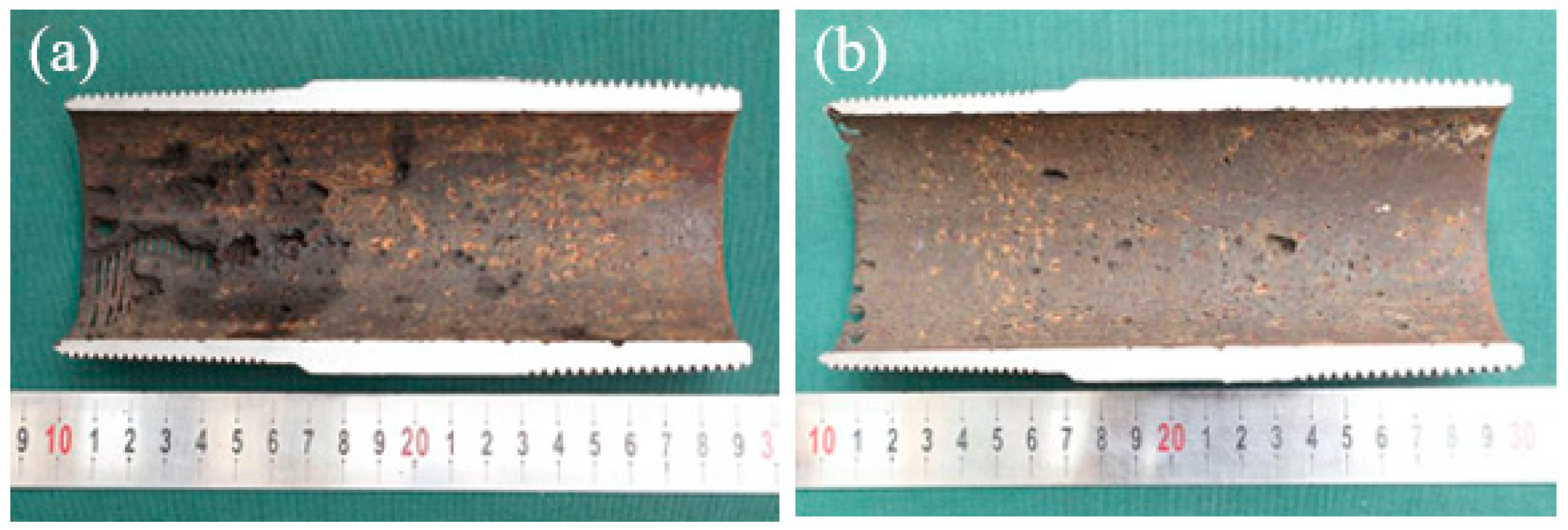
Figure 6 shows the macroscopic morphology of the inner wall of the double male coupling short section. As shown in the figure, the inner wall is severely corroded, and the overall surface is yellowish-brown. At the same time, several corrosion pits of different sizes are distributed on the inner wall, and in some areas, the pits are dense. The corrosion degree near the flat end is particularly prominent, presenting a large area of metal loss, but no obvious corrosion products are observed, showing the typical characteristics of fluid erosion corrosion.
Figure 6.
Macroscopic morphology of the inner wall of the double-male crossover sub: (a) 0°, (b) 180°.
3.2. Analysis of Microscopic Corrosion Morphology and Corrosion Products
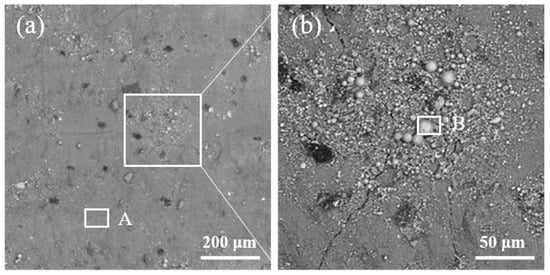
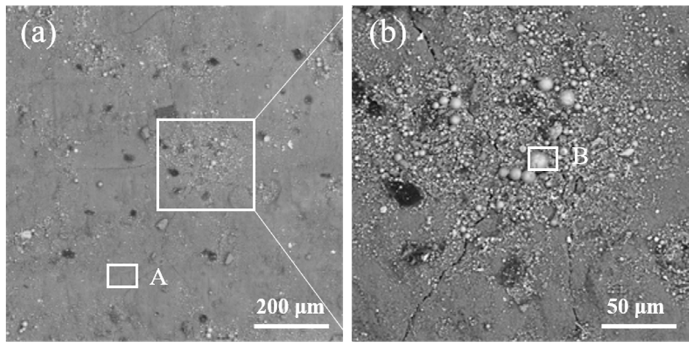
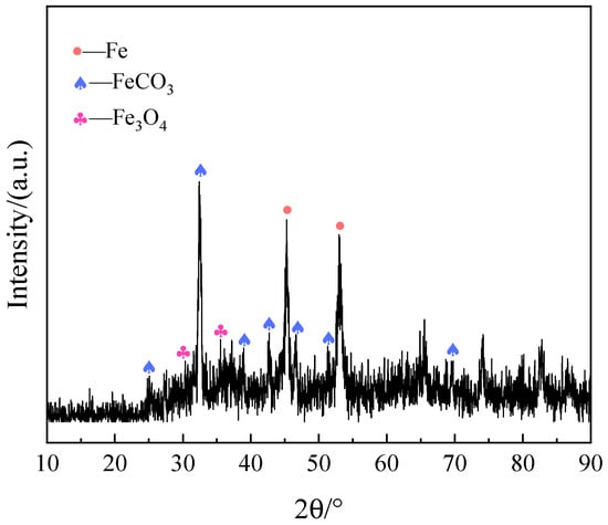
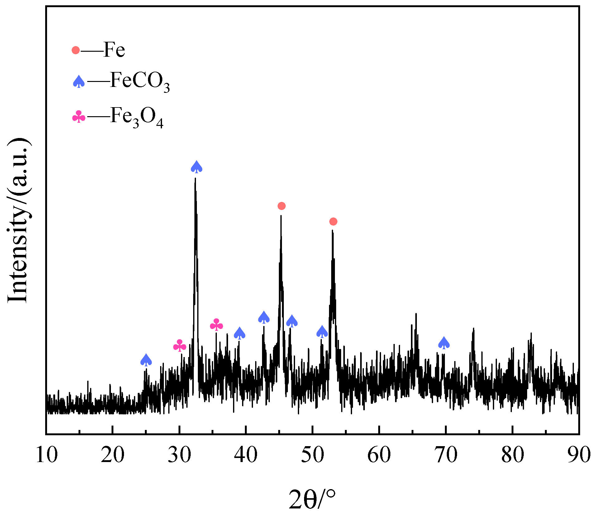
Samples were taken from the severely corroded areas on the inner wall section, and corrosion products on the inner surface were analyzed. Figure 7 shows the microscopic morphology of the corroded area. As shown in the figure, the surface corrosion products have a layered structure. The lower layer of products is relatively complete in coverage, but local cracking occurs. The surface products are scattered on the lower-layer products, mostly spherical, and the particle sizes are not uniform. EDS analysis was performed on the out-layer product (Region A) and the inner-layer product (Region B), and the results are shown in Table 2. The table shows that the main elements in the lower-layer corrosion products are Fe, C, and O; the spherical particles on the surface layer are mainly composed of Fe. Combined with the XRD analysis results (see Figure 8), the inner-surface corrosion products are mainly iron oxides (Fe3O4) and FeCO3. Thus, the inner wall mainly undergoes O2 and CO2 corrosion.
Figure 7.
Microscopic corrosion morphology of the inner surface: (a) low-magnification overview, with region A selected for EDS analysis; (b) high-magnification morphology of the boxed area in (a), with region B selected for EDS analysis.
Table 2.
EDS analysis results of corrosion products on inner surface.
Figure 8.
XRD analysis spectrum of the corrosion products on the inner wall of the short section.
3.3. Analysis of Flow Field-Induced Accelerated Corrosion Mechanism
3.3.1. Simulation of Flow Field in the “J” Shape Area of the Coupling Ring
Investigation of API tubing corrosion failures shows that corrosion damage is mostly concentrated in the tubing joint area. For API coupling-connected tubing, after the upper and lower couplings are connected, a 25.4 mm-wide groove (i.e., the “J” shape area) forms in the middle of the coupling. To explore whether corrosion of the tubing joint is related to its structural shape and how changes in flow patterns through the joint’s groove area affect corrosion behavior, this study uses computational fluid dynamics (CFD) for numerical simulation.
Based on the geometric structure of the upper and lower pipe columns connected by the failed double male coupling short section, while considering the existence of the central pipe inside the tubing, a three-dimensional finite element model of the pipe column was established, as shown in Figure 1. Based on the CFD software, the flow field in the annular space between the central pipe and the tubing was numerically simulated, with a focus on analyzing the pressure and velocity distribution characteristics of the flow regime transition area on the inner wall of the double male coupling. The flowing medium in the annular space is mainly the produced liquid. According to the on-site pipe column structure design, the coupling with the center pipe coupling at the lower end of short section of the double male coupling is arranged in a centered and opposite position.
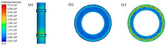
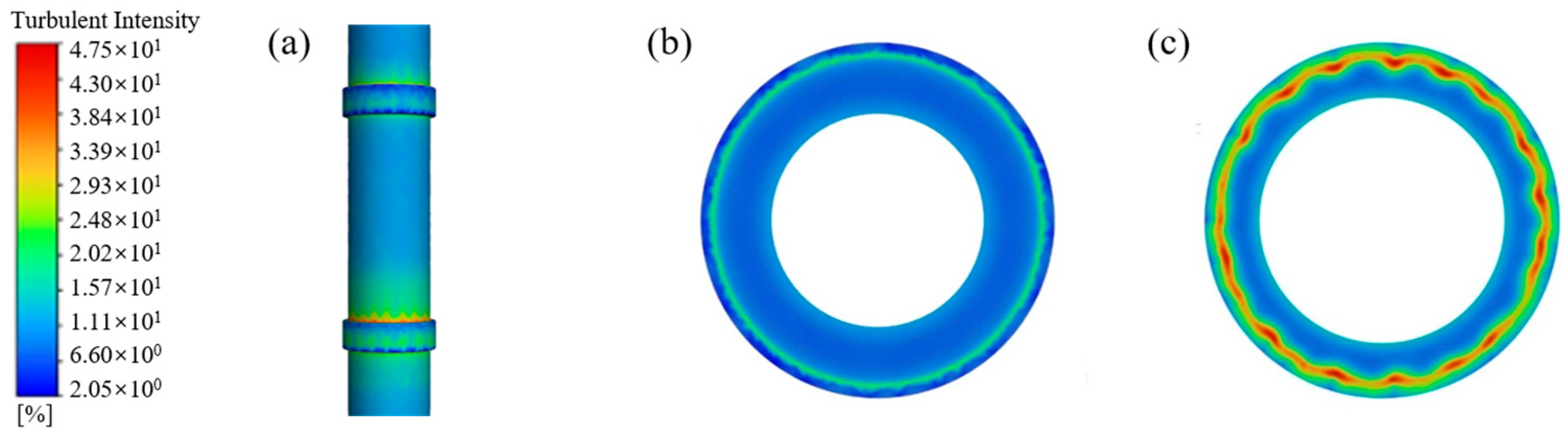
The turbulence intensity distribution of the fluid within the tubular string is presented in Figure 9. As shown in the figure, the red area represents higher turbulence intensity, while the blue area corresponds to lower turbulence intensity, clearly reflecting spatial differences in the degree of flow-field disorder. In the “J” shape area of the upper and lower couplings connected by the short section, significant high turbulence intensity areas (mainly red/yellow) appeared, especially at the upper edge of the “J” shape area of the lower coupling, indicating that the structure gap at this location caused intense flow field disturbance. In contrast, the turbulence intensity in the pipe body and the main body of the coupling remains relatively low, indicating a comparatively stable flow regime.
Figure 9.
Contour of turbulence intensity distribution on the inner wall of the double-male crossover sub: (a) overall, (b) lower edge of the upper coupling, (c) upper edge of the lower coupling.
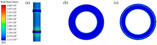
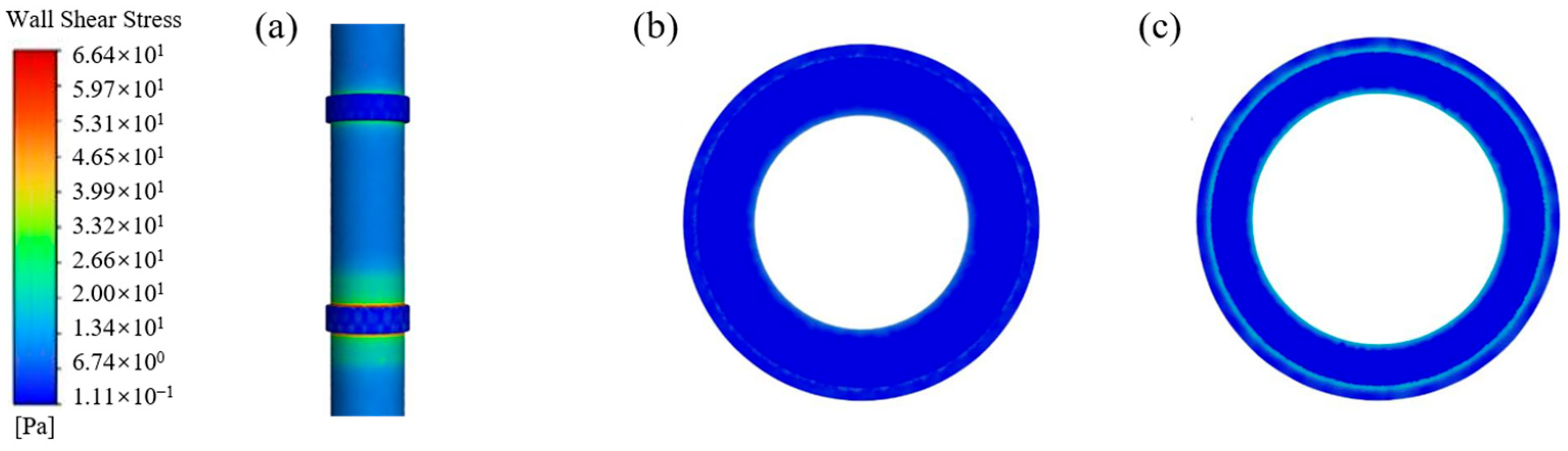
Figure 10 presents the contour of wall shear stress distribution on the inner wall of the tubular string, providing a direct visualization of the spatial variation in the shear action exerted by the fluid on the pipe wall. As shown in the figure, pronounced high-shear-stress zones occur at both the upper and lower edges of the “J”-shaped groove of the lower coupling connected to the double-male crossover sub, indicating that fluid shear stress on the pipe wall is most intense in these regions. In contrast, the “J”-shaped groove of the upper coupling and the pipe body sections exhibit relatively low shear stress levels. Wall shear stress is closely associated with the risk of erosion-wear damage. Sustained fluid shear in high-shear-stress zones not only accelerates the removal of pipe wall material but also readily entrains solid particles, further exacerbating the abrasive effect. Consequently, these regions are identified as critical zones for erosion damage.
Figure 10.
Contour of wall shear stress distribution on the inner wall of the double-male crossover sub: (a) overall, (b) lower edge of the upper coupling, (c) upper edge of the lower coupling.
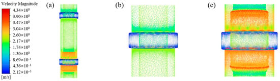
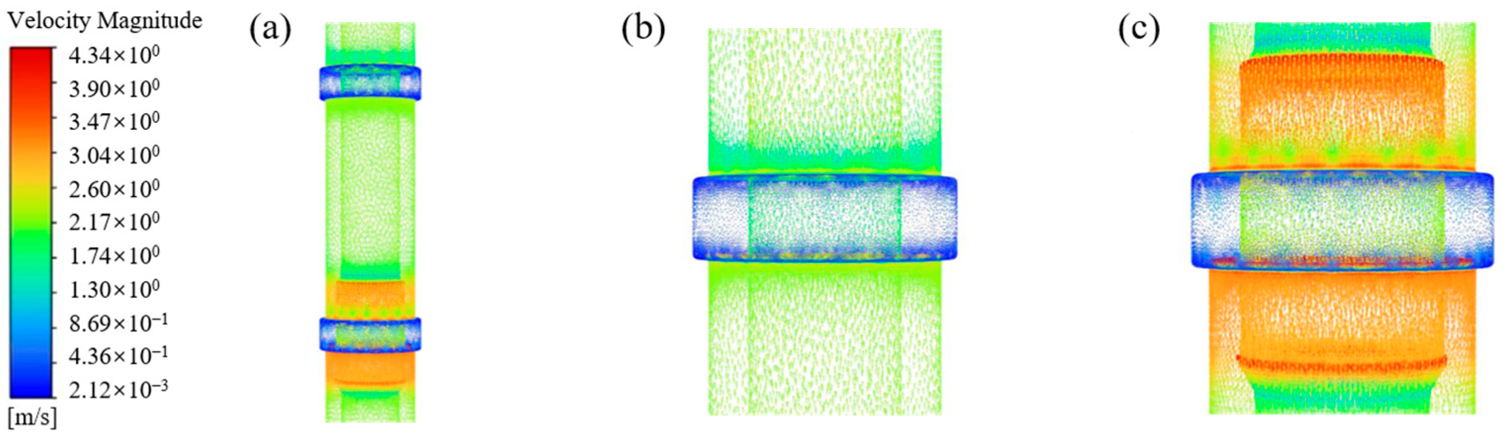
Figure 11 shows the contour of fluid velocity vector distribution within the tubular string. As shown in the figure, the “J”-shaped groove regions of both the upper and lower couplings connected to the double-male crossover sub belong to low-velocity stagnation zones, where the fluid flow is relatively quiescent and tends to facilitate the deposition of solid particles. The relatively smooth flow likely causes solid particles to deposit in this area. At the same time, the direction of the velocity vectors in this area is relatively dispersed, indicating that there is a local disorder in the flow field. The upper and lower edges of the “J” shaped area of the lower coupling ring present obvious high-speed flow zones, indicating that the impact of the fluid is strongest here. The upper and lower edges of the “J” shaped area of the upper coupling ring and the pipe body area are medium-speed flow zones, with the fluid flow direction being relatively concentrated, but the vector arrows with directional deflection further intensify the disorder of the flow field to a certain extent.
Figure 11.
Contour of fluid velocity vector distribution in the “J”-shaped groove region of the double-male crossover sub coupling: (a) overall, (b) lower edge of the upper coupling, (c) upper edge of the lower coupling.
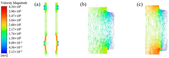
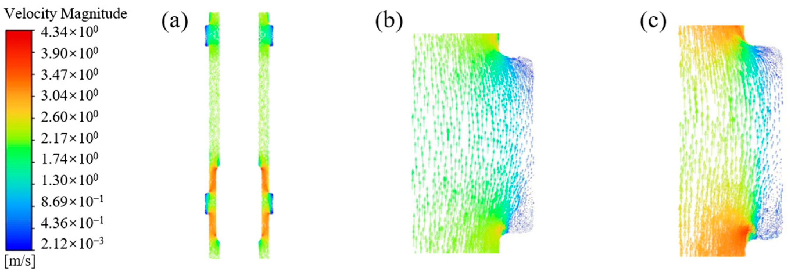
Figure 12 shows the cloud diagram of the fluid velocity vector distribution in the annular space between the inner wall of the tubing and the outer wall of the central tube. From the figure, it can be seen that the “J” shaped area is a low-speed stagnant flow zone, and the flow field presents a low-speed stagnant state with local recirculation. The flow velocity in this area is significantly lower than that in the surrounding areas, and the fluid flow is smooth, which is conducive to the formation of medium stagnation; at the same time, the direction of the velocity vector is dispersed and the density is low, indicating that there are weak recirculations and local flow disorders in the flow field. The upper and lower edges of the “J” shape area of the lower coupling show high flow velocity zones, with a sharp increase in flow velocity, indicating that the fluid impact at this location is strongest. While the upper and lower edges of the “J” shape area of the upper coupling show no obvious change in the flow field and no significant increase in flow velocity.
Figure 12.
Contour of fluid velocity vector distribution in the annular space between the inner wall of the double-male crossover sub and the outer wall of the central pipe: (a) overall view; (b) “J”-shaped groove region of the upper coupling; (c) “J”-shaped groove region of the lower coupling.
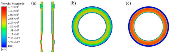
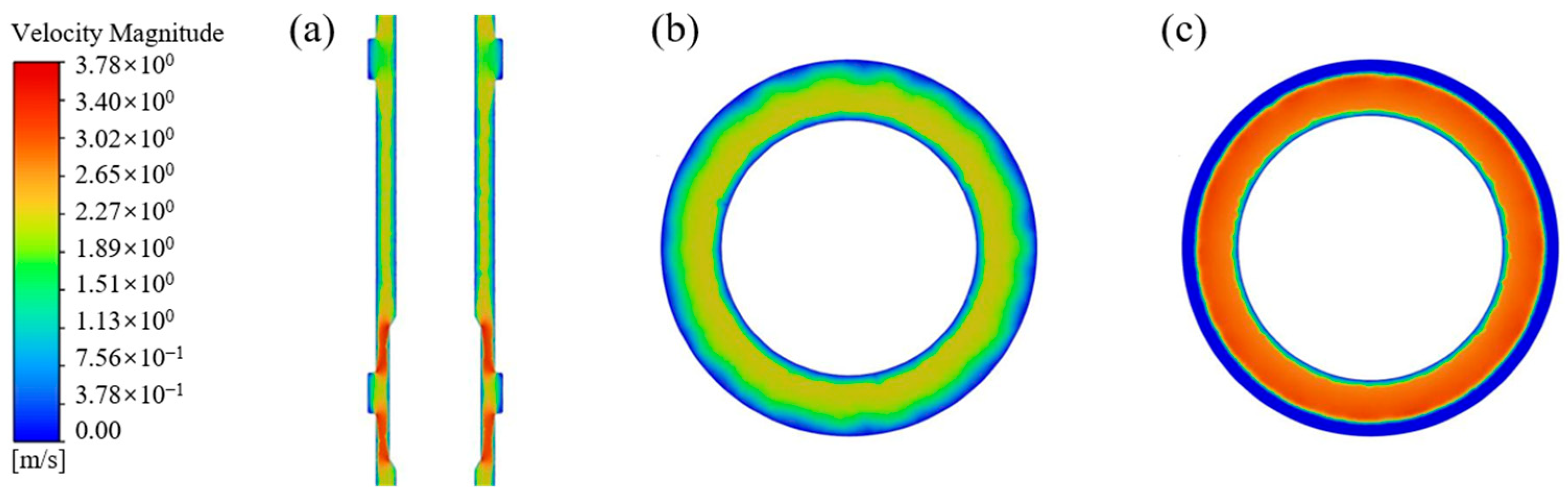
Figure 13 shows the cross-sectional distribution cloud map of the fluid velocity in the annular space between the inner wall of the double public transformer coupling short section and the outer wall of the central tube. As can be seen from the figure, the velocity is highest in the central area of the annular space, gradually decreasing near the inner wall of the oil pipe and the outer wall of the central tube, and the velocity is the lowest in the middle position of the “J” shape area of the oil pipe coupling “J” shape section, which is 0.13 m/s. Low velocity causes the corrosive medium to stagnate locally, forming a concentration cell and accelerating the corrosion rate at the coupling “J” shape area. There are obvious high-velocity zones at the upper and lower edges of the “J” shape area, with the velocity at the lower edge of the “J” shape area being 2.61 m/s and that at the upper edge being 2.58 m/s, indicating that the velocity gradient in this area is large and the fluid disturbance is intense, which is prone to induce the synergistic effect of erosion and corrosion.
Figure 13.
Cross-sectional distribution of fluid velocity in the annular space between the inner wall of the double-male crossover sub and the outer wall of the central pipe: (a) overall view; (b) center of the “J”-shaped zone on the upper coupling; (c) upper edge of the “J”-shaped zone on the lower coupling.
Table 3 presents the simulation results for wall shear stress, flow velocity, and flow state in the “J” shaped area and the main flow area of the upper and lower coupling rings of the double male coupling short section. As can be seen from the table, in the area where the recirculation vortex intersects with the main flow body in the “J” shape area, the flow velocity is high and the shear stress is concentrated; while in the vortex center area, the shear stress is extremely small and the flow velocity is extremely low, which is prone to cause solid phase particles and corrosive media to remain here.
Table 3.
Simulation results of the “J”-shape groove region of the tubing coupling.
3.3.2. Failure Mechanism
Based on corrosion morphology observations, corrosion product phase analysis, and CFD flow field simulation results, the failure of the N80 steel double-male crossover sub is attributed to the synergistic effect of corrosive media attack and flow-induced erosion in the “J”-shaped groove region of the coupling. The failure mechanism is elaborated below from two aspects: the electrochemical corrosion process and the hydrodynamic process.
(1) The process of CO2 and O2 synergistic corrosion
The failed section is located at a depth of 1220.03 m to 1220.15 m in the well. The temperature of this well section is approximately 33.61 °C. The bottom hole pressure is approximately 10.15 MPa. Based on the gas component results, the partial pressure of CO2 in this well is 1.62 to 1.88 MPa, with an average partial pressure of 1.78 MPa, and the partial pressure of O2 is 0.02 to 0.06 MPa, with an average partial pressure of 0.03 MPa. XRD and EDS results indicate that the internal wall corrosion products are mainly iron oxides and FeCO3, and that the corrosion type is electrochemical corrosion under the combined action of CO2 and O2. In the CO2-O2 coexisting environment, the corrosion process is not a simple superposition of the effects of the two gases, but there are complex interactive influences [23].
CO2 dissolves in water to form a weakly acidic environment, which promotes the anodic dissolution of the steel substrate and the release of Fe2+. The dissociation of CO2 in water proceeds as follows [24]:
CO2 + H2O ⇄ H2CO3
H2CO3 ⇄ H+ + HCO3−
HCO3− ⇄ 2H+ + CO32−
The H+ released by this dissociation promotes the anodic dissolution of Fe:
Fe − 2e−→ Fe2+
When the ion product of the concentration of Fe2+ near the wall surface and that of CO32− exceeds the solubility product of FeCO3 (Ksp = 3.13 × 10⁻¹¹), FeCO3 deposits on the steel surface, resulting in the reaction (5):
Fe2+ + CO32− → FeCO3(s)
The inherent protective property of the FeCO3 membrane depends on its density and structural integrity [25]. At the wellbore temperature of 33.6 °C in the interval where the failed sub was located, the FeCO3 film can hardly form a dense and stable protective layer, and thus provides limited effective protection to the substrate [26]. This is consistent with the SEM and XRD results-the corrosion products are dominated by Fe3O4 and FeCO3, which offer poor protection to the substrate, and the presence of Fe3O4 further indicates that O2 participated in the corrosion process.
In addition, the well is produced by jet pump technology, which involves an aeration step in which atmospheric O2 enters the wellbore. It participates in the cathodic process through the following reaction and accelerates corrosion [27,28]:
O2 + 2H2O + 4e−→4OH
Fe 2+ + 2OH−→Fe(OH)2
4Fe(OH)2 + 2O2 + 2H2O→4Fe(OH)3
2Fe(OH)3→Fe2O3 + 3H2O
Fe(OH)3→FeO(OH) + H2O
Fe2+ + 8FeOOH + 2e−→3Fe3O4 + 4H2O
O2 oxidizes Fe2+ to Fe3+, causing the oxidation and decomposition of FeCO3. The iron oxides (Fe2O3, Fe3O4, FeOOH) and the FeCO3 crystals deposit together, reducing adhesion between the FeCO3 crystals and resulting in a loose, porous film layer that offers no protection to the substrate [23,29]. The produced fluid in this well has a salinity of 11,778–13,295 mg/L, with a Cl− concentration of approximately 1550 mg/L and an ionic strength of about 0.25–0.30 mol/kg. The presence of Cl− makes FeCO3 precipitation more difficult, thereby hindering the formation of an effective protective layer [22]. This is also supported by the macroscopic morphology-relatively little corrosion product is observed on the inner wall of the sub.
(2) High shear force—vortex retention combined with erosion effect
The middle part of the API coupling has a 25.4 mm groove, forming a J-shaped, geometrically discontinuous structure. When fluid flows through this area, the flow field undergoes a drastic reconfiguration. CFD quantitatively simulates the mechanical behavior of the partition and forms two different corrosion acceleration mechanisms.
On the one hand, at the upper and lower edges of the J-shaped zone, the simulation measured the maximum wall shear stress of the failed double male coupling short section’s collar at the upper edge of the J-shaped zone to be 58.5 Pa, and at the lower edge to be 46.22 Pa, which was much higher than the 31.18 Pa in the main flow zone; the fluid velocity in this area reached 2.58 to 3.25 m/s, and the turbulence intensity was at the peak of the entire region. Under continuous high shear, the interface bonding force of the loose porous FeCO3-iron oxide composite film was insufficient to resist the fluid shear load, resulting in large-scale mechanical peeling and exposing the substrate. The exposed metal then rapidly corroded again. A repetitive “scouring-corrosion-re-scouring” cycle formed [19,30]. At the same time, the trace SiO2 solid particles in the formation water are impacted by the high-speed fluid at the upper and lower edges, causing a combined action of scraping and micro-cutting on the corrosion interface [31,32], which further aggravates the failure of the short section.
On the other hand, in the J-shaped central vortex stagnation zone, extremely low flow velocity leads to the accumulation of corrosive media, intensifying local electrochemical corrosion. A stable recirculation vortex forms at the center of the J-shaped groove, with the lowest flow velocity being only 0.13 m/s. The fluid convective mass transfer nearly stops, forming a stagnant zone where the medium is retained. Corrosive media such as CO2, dissolved O2, Cl−, and H+ continuously accumulate in the vortex zone. The local ion concentration is significantly higher than that of the main flow, greatly enhancing the kinetics of anodic and cathodic reactions. A macroscopic galvanic couple is formed between the stagnant zone and the high-speed erosion edge. The vortex-rich area acts as the anode and is preferentially dissolved, while local corrosion pits continue to deepen in a longitudinal direction by [33,34,35]. In a low-speed environment, SiO2 solid particles and corrosion product fragments deposit at the bottom of the groove, forming blocked corrosion gaps. The medium inside the gaps is continuously acidified, and the concentration cell effect continuously amplifies, causing the corrosion pits to rapidly deepen along the wall thickness direction.
In conclusion, the binary partition flow field caused by the J-shaped groove geometric discontinuity is the structural root of local corrosion concentration. The synergistic effect of CO2 and O2 in generating an unprotected loose corrosion film is the medium foundation for the continuous development of corrosion. The coupling of these two factors ultimately leads to large-scale metal loss on the inner wall of the short section and local perforation in the threaded area.
4. Conclusions
- (1)
- The synergistic effect of CO2 and O2 promotes corrosion of the sub. The corrosion products on the N80 double-male crossover sub in this coalbed methane well are dominated by Fe3O4 and FeCO3, and XRD and EDS results indicate that the corrosion type is electrochemical corrosion under the combined action of CO2 and O2. CO2 serves as the primary corrosive medium, while O2 introduced through the aeration step of the jet pump process acts as a cathodic depolarizer, accelerating the cathodic reaction. The resulting corrosion product film is loose and porous, offering poor protection to the substrate, and the high Cl− concentration further inhibits the formation of a protective FeCO3 film.
- (2)
- Flow field reconstruction at the “J”-shaped region of the coupling promotes wall thinning of the sub. At the edge of the “J”-shaped groove in the central region of the API coupling, a high shear turbulent zone forms (peak wall shear stress of 58.5 Pa), which continuously strips off the loose corrosion product film and exposes the highly active metal surface. At the groove center, a low-velocity vortex retention zone forms (flow velocity of only 0.13 m/s), where corrosive species such as CO2, O2, Cl−, and H+ accumulate and induce concentration cell corrosion. The combined action of electrochemical corrosion, scouring removal, and corrosive species enrichment lead to substantial wall thinning, extensive metal loss at the plain-end pin-threaded region. Accordingly, for jet pump production, special threaded joint with a face seal structure (axial seal) are recommended to eliminate the “J”-shaped region and reduce the risk of erosion corrosion and wear-corrosion.
Author Contributions
Conceptualization, Y.C. and J.Z.; methodology, Y.G., X.L. and J.W.; validation, W.Z. and Q.Z.; formal analysis, Q.Y. and J.Q.; investigation, J.W.; resources, Y.C., J.Z. and Q.L.; data curation, Y.B. and Q.L.; writing—original draft preparation, W.Z. and Q.Z.; writing—review and editing, Y.C. and W.Z.; visualization, L.M. and Q.F.; supervision, W.Z.; project administration, Y.C.; funding acquisition, J.Z. All authors have read and agreed to the published version of the manuscript.
Funding
This research was supported by the Science and Technology Program of Xinjiang Uyghur Autonomous Region (No. 2023A01004, 2023A01004-5), the Natural Science Basic Research Program of Shaanxi (Program No. 2025JC-YBMS-613, 2025JC-YBMS-466), and the Postgraduate Innovation and Practice Ability Development Fund of Xi’an Petroleum University (YCS23214299).
Data Availability Statement
The original contributions presented in this study are included in the article. Further inquiries can be directed to the corresponding author(s).
Conflicts of Interest
Authors Yumiao Cui, Jian Zhang, Yongjun Guo, Jiaying Wu, Quan Yuan, Jiang Qin, Lei Ma, and Qiang Fu were employed by Xinjiang Yaxin Oil & Gas Co., Ltd. Author Yumiao Cui was also employed by Xinjiang Yaxin Coalbed Methane Investment & Development (Group) Co., Ltd. and Xinjiang Yaxin Coalbed Methane Resources Technology Research Co., Ltd. Yongjie Bao and Qiang Li were employed by Xinjiang Yaxin Coalbed Methane Resources Technology Research Co., Ltd. The remaining authors declare that the research was conducted in the absence of any commercial or financial relationships that could be construed as a potential conflict of interest.
References
- Chen, W.; Di, Q.; Zhang, H.; Chen, F.; Wang, W. The sealing mechanism of tubing and casing premium threaded connections under complex loads. J. Pet. Sci. Eng. 2018, 171, 724–730. [Google Scholar] [CrossRef] [Scilit]
- Yan, R.; Wang, F.; Zhang, D.; Zhu, H.; Zeng, D. Failure analysis of API tubing round threaded connection induced by flow field. Pet. Drill. Tech. 2012, 40, 111–114. [Google Scholar]
- Yang, G.; Wang, X.; Yan, L.; Huang, T.; Li, Z.; Ma, H.; Sun, B.; Liu, Z.; Li, X. Failure behavior and mechanism of N80 tubing threaded joints in CO2 flooding production well. Eng. Fail. Anal. 2026, 191, 110811. [Google Scholar] [CrossRef] [Scilit]
- Zhang, H.; Wang, G.; Zhao, J.; Deng, B.; Zhang, L. Failure analysis of tripping tubing in an oilfield. J. Fail. Anal. Prev. 2022, 22, 1268–1275. [Google Scholar] [CrossRef] [Scilit]
- Zhu, S.; Wei, J.F.; Cai, R.; Bai, Z.Q.; Zhou, G.S. Corrosion failure analysis of high strength grade super 13Cr-110 tubing string. Eng. Fail. Anal. 2011, 18, 2222–2231. [Google Scholar] [CrossRef] [Scilit]
- Zhou, Z.; Gong, D.; Zeng, Z.; Lin, T. Failure analysis of a four-way flange erosioning in a KQ52 wellhead Christmas tree. Eng. Fail. Anal. 2021, 129, 105641. [Google Scholar] [CrossRef] [Scilit]
- Yang, Y.; He, M.; Yu, P.; Kan, C.; Wang, X.; Yu, X.; Chen, X.; Tao, S.; Zhao, C.; Duan, J.; et al. Investigation on critical erosion of gas production channel for sand carrying during injection and production process in gas storage. Geoenergy Sci. Eng. 2024, 239, 212945. [Google Scholar] [CrossRef] [Scilit]
- Yuan, G.; Yao, Z.; Han, J.; Wang, Q. Stress distribution of oil tubing thread connection during make and break process. Eng. Fail. Anal. 2004, 11, 537–545. [Google Scholar] [CrossRef] [Scilit]
- Shi, T.; Qi, Z.; Liu, C.; Li, X. Tension and torsion distributions in tapered threaded connections. Int. J. Mech. Sci. 2025, 291–292, 110135. [Google Scholar] [CrossRef] [Scilit]
- Wang, Z.; Yao, Z.; Meng, Y.; Ju, L.; Chen, S.; Ji, B.; Shi, J. Failure mechanism of low-pressure leakage in small-diameter API EU tubing induced by friction-controlled make-up position. Eng. Fail. Anal. 2026, 187, 110597. [Google Scholar] [CrossRef] [Scilit]
- Li, S.; Li, X.; Zhang, R. Failure assessment of injection tubing in high pressure dense-phase CO2 injection well. Eng. Fail. Anal. 2026, 183, 110284. [Google Scholar] [CrossRef] [Scilit]
- Chen, Q.; Yang, W.; Li, M.; Yang, L.; Zhu, J. Study on the influence of radial load on the fastening characteristics of oil pipe joints. China Mech. Eng. 2026, 2026, 1–10. [Google Scholar]
- van Riet, E.; Van Wittenberghe, J.; Van Hoecke, D.; Roijmans, R.; Vanderschueren, M.; Thibaux, P. On the suitability of premium OCTG tubing connections for CCS CO2 injection wells—A full scale physical evaluation. Int. J. Greenh. Gas Control 2023, 123, 103834. [Google Scholar] [CrossRef] [Scilit]
- Obaseki, M.; Nwankwojike, B.N.; Abam, F.I. Diagnostic and prognostic development of a mechanistic model for multiphase flow in oil-gas pipelines. J. King Saud Univ.-Eng. Sci. 2022, 34, 562–570. [Google Scholar] [CrossRef] [Scilit]
- Feng, D.; Li, Y.; An, J.; Yang, Z.; Wang, Y.; Ni, J. Cause analysis of corrosion and performance of tubing pup joint in water injection well at offshore oil field. Corros. Prot. Petrochem. Ind. 2024, 41, 52–58. [Google Scholar]
- Xu, H.; Zhang, C.; Xiang, S.; Gao, Q.; Zhang, Z.; Shi, T. A prediction method for sustained casing pressure due to leakage of premium connection for tubing strings in deep gas wells. Geoenergy Sci. Eng. 2026, 266, 214616. [Google Scholar] [CrossRef] [Scilit]
- Chen, R.; Li, W.; Tian, Z.; Wang, W.; Wu, B.; Zhang, H.; Liu, W.; Ma, Y. Research on the erosion damage mechanism and structural optimization design of tubing couplings. In Computational and Experimental Simulations in Engineering; Springer Nature: Cham, Switzerland, 2026; pp. 357–377. [Google Scholar]
- Xian, Q.; Lin, Y.; Li, Y.; Zhu, H.; Xia, T.; Yan, R. Numerical simulation analysis of flow field inducing factors in drill string’s failure. Oil Field Equip. 2010, 39, 35–38. [Google Scholar]
- Tan, Z.; Yang, L.; Wang, Z.; Dou, X.; Zhang, D.; Zhang, M.; Jin, Y. Study on interaction mechanism of local turbulent flow induced by local corrosion of X80 pipeline steel in high shear flow field. J. Chem. Ind. Eng. 2021, 72, 2203–2212. [Google Scholar]
- Ahmed, T.M.; Alfantazi, A.; Budac, J.; Freeman, G. Failure analysis of 316L stainless steel tubing of the high-pressure still condenser. Eng. Fail. Anal. 2009, 16, 1432–1441. [Google Scholar] [CrossRef] [Scilit]
- Malka, R.; Nešić, S.; Gulino, D.A. Erosion–corrosion and synergistic effects in disturbed liquid-particle flow. Wear 2007, 262, 791–799. [Google Scholar] [CrossRef] [Scilit]
- Gu, J.; Xing, K.; Xue, W. Corrosion Mechanisms and Precision Protection Technologies for Deep Coalbed Methane Wells in Fukang, Xinjiang. J. Oil Gas Technol. 2026, 48, 280–292. [Google Scholar]
- Wang, Z.; Li, X.; Li, X.; Zhu, S.; Liang, X.; Yuan, J.; Fu, A. Research progress of corrosion behavior of petroleum pipes under mutifactor coupling of CO2/O2 and CO2/H2S/O2. Corros. Prot. 2026, 47, 1–6+72. [Google Scholar]
- Wang, X.; Wang, X.; Wang, J.; Wang, G.; Pan, Y.; Yan, S. The Influence of O2 on the Corrosion Behavior of the X80 Steel in CO2 Environment. Int. J. Electrochem. Sci. 2020, 15, 889–898. [Google Scholar] [CrossRef] [Scilit]
- Matamoros-Veloza, A.; Barker, R.; Vargas, S.; Neville, A. Mechanistic insights of dissolution and mechanical breakdown of FeCO3 corrosion films. ACS Appl. Mater. Interfaces 2021, 13, 5741–5751. [Google Scholar] [CrossRef] [Scilit] [PubMed]
- Dana, M.M.; Javidi, M. Corrosion simulation via coupling computational fluid dynamics and NORSOK CO2 corrosion rate prediction model for an outlet header piping of an air-cooled heat exchanger. Eng. Fail. Anal. 2021, 122, 105285. [Google Scholar] [CrossRef] [Scilit]
- Leng, J.; Frank Cheng, Y.; Liao, K.; Huang, Y.; Zhou, F.; Zhao, S.; Liu, X.; Zou, Q. Synergistic effect of O2-Cl− on localized corrosion failure of L245N pipeline in CO2-O2-Cl− environment. Eng. Fail. Anal. 2022, 138, 106332. [Google Scholar] [CrossRef] [Scilit]
- Dong, B.; Liu, W.; Wu, F.; Zhu, J.; Wongpat, B.; Zhao, Y.; Fan, Y.; Zhang, T. Determination of critical salinity of pitting and uniform corrosion of X60 under CO2-O2 coexistence environment. Anti-Corros. Methods Mater. 2020, 67, 166–177. [Google Scholar] [CrossRef] [Scilit]
- Tavangar, R.; Simons, A.; Verbeken, K.; Depover, T. From bicarbonate supersaturation to sweet corrosion: A multiscale study of FeCO3 film development on pipeline steels. Eng. Fail. Anal. 2026, 196, 111060. [Google Scholar] [CrossRef] [Scilit]
- Luo, X.; Wang, K.; Zhao, Q. The influence mechanism of flow-interface-reaction interaction on the erosion-corrosion synergistic damage of liquid-solid two-phase flow. Sci. Sin. Technol. 2026, 56, 1810–1824. [Google Scholar] [CrossRef] [Scilit]
- Du, Y.; Yang, G.; Chen, S.; Ren, Y. Research on the erosion-corrosion mechanism of 304 stainless steel pipeline of mine water in falling film flow. Corros. Sci. 2022, 206, 110531. [Google Scholar] [CrossRef] [Scilit]
- Yang, G.; Xiong, S.; Li, Y.; Luo, J.; Wang, X. Cause analysis of countermeasures of tubing failure in injection well of Nanhai E Oilfiel. Petrochem. Ind. Technol. 2025, 32, 70–72. [Google Scholar]
- Rameshk, M.; Soltanieh, M.; Masoudpanah, S.M. Effects of flow velocity and impact angle on erosion-corrosion of an API-5 L X65 steel coated by plasma nitriding of hard chromium underlayer. J. Mater. Res. Technol. 2020, 9, 10054–10061. [Google Scholar] [CrossRef] [Scilit]
- Zhang, S.; Hou, L.; Wei, H.; Wei, Y.; Liu, B. Failure analysis of an oil pipe wall perforated by pitting corrosion. Mater. Corros. 2018, 69, 1123–1130. [Google Scholar] [CrossRef] [Scilit]
- Eliyan, F.F.; Alfantazi, A. Mechanisms of corrosion and electrochemical significance of metallurgy and environment with corrosion of iron and steel in bicarbonate and carbonate solutions—A review. Corrosion 2014, 70, 880–898. [Google Scholar] [CrossRef] [Scilit] [PubMed]

Disclaimer/Publisher’s Note: The statements, opinions and data contained in all publications are solely those of the individual author(s) and contributor(s) and not of MDPI and/or the editor(s). MDPI and/or the editor(s) disclaim responsibility for any injury to people or property resulting from any ideas, methods, instructions or products referred to in the content. |
© 2026 by the authors. Licensee MDPI, Basel, Switzerland. This article is an open access article distributed under the terms and conditions of the Creative Commons Attribution (CC BY) license.