


Abstract
Metal corrosion and microbial contamination cause severe damage to marine facilities and result in immeasurable economic losses. Highly efficient and durable anti-corrosion and anti-fouling coatings represent the most effective solution strategy widely employed, whilst two-dimensional graphitic carbon nitride (g-C3N4), owing to its non-toxic and highly effective properties, is frequently utilized as a coating filler. Herein, this work innovatively engineered g-C3N4 into rod-like structures with layer-oriented alignment through a two-step simplified synthesis process, naturally achieving the self-assembly integration of ultrathin sheets. Subsequently, the special rod-like g-C3N4 (RCN) was blended with a polydimethylsiloxane (PDMS) matrix, ultimately yielding a multifunctional nanocomposite coating (RCN/PDMS) that combines mechanical reinforcement, long-term corrosion resistance, and microbial fouling protection. Notably, the compact lamellar structure within uniformly dispersed RCN particles in the polymer matrix effectively enhances the crosslinking density of the composite, significantly improving the coating’s adhesion and tensile strength (1.795 MPa). Furthermore, upon exposure to light, the modified RCN-2 releases substantial reactive oxygen species (ROS), exhibiting pronounced antibacterial activity (90.3% of E. coli and 95.1% of S. aureus) against surface-adhering microorganisms. Following a 60 d marine immersion simulation test, the impedance arc radius of the RCN-2/PDMS coating remained as high as 5.17 × 10⁹ Ω·cm2, representing an improvement of nearly two orders of magnitude over pure PDMS coatings. This work expands the application of morphology-controlled g-C3N4-based fillers in marine anti-fouling and anticorrosion coatings.
1. Introduction
Globally, metal corrosion, as a persistent and pervasive form of material degradation, incurs economic losses amounting to approximately US $2.5 trillion annually, representing 3–4% of the total annual output [1,2], which not only poses a serious threat to the safety and reliability of industrial facilities but also imposes long-term constraints on energy consumption and resource utilization efficiency [3]. Whilst traditional anti-corrosion techniques, exemplified by chromate coatings, offer relatively enduring protection, their potent carcinogenicity and inherent environmental toxicity subject them to stringent restrictions under the dual imperatives of modern green manufacturing and sustainable development [4]. Consequently, driven by mounting concerns over resource scarcity and ecological impact, the corrosion protection sector now faces a critical demand for innovative solutions that are both high-performing and environmentally sustainable [5].
Over the past decade, employing clean solar energy to generate reactive oxygen species (ROS) via photocatalytic materials for the inactivation of microorganisms has emerged as an innovative strategy [6]. By utilizing the band structure of semiconductor materials, photo-generated electrons and holes react with O2 and H2O adsorbed onto the coating surface, producing reactive species, including superoxide radicals (·O2−) and hydroxyl radicals (·OH) and thereby destroying microbial cell walls [7]. When a photocatalyst is incorporated into a coating matrix as a functional filler, it not only enhances the physical barrier effect through the ‘maze effect’ but the light-induced ROS also endows the coating with the ability to resist biofouling [8]. Among numerous photocatalytic materials, graphitic carbon nitride (g-C3N4) is widely regarded as an ideal candidate for photocatalytic generation of ROS to achieve anti-fouling properties due to its non-toxicity, non-metallic nature, ease of preparation, excellent chemical stability, and suitable bandgap width [9]. Its two-dimensional layered structure forms a ‘labyrinth effect’ that effectively retards the diffusion of corrosive media within the coating, thereby providing physical barrier protection [10,11]. However, bulk g-C3N4 still faces inherent limitations such as a low specific surface area, high charge recombination rate, and limited active sites, severely restricting its practical application performance in complex corrosion systems [12]. Extensive research indicates that enhancing the specific surface area of g-C3N4 by regulating its morphological structure, modulating its energy band structure, and promoting the separation and migration of photogenerated carriers constitutes an effective strategy for overcoming its application limitations [13,14]. Consequently, diverse structural engineering approaches are being continuously developed, including the fabrication of ultrathin nanosheets, nanomembranes, and composite materials with specialized morphologies [15,16]. For example, Sun et al. combined ultrathin g-C3N4 nanosheets prepared via a secondary thermal exfoliation method with highly conductive graphene to fabricate a composite structure rich in carbon dioxide adsorption sites, which significantly prolongs carrier lifetime and enhances barrier properties, thereby effectively inhibiting the diffusion of corrosive ions [17]. Similarly, Yang et al. employed a one-step chemical vapor deposition method using urea as a precursor to deposit g-C3N4 films onto magnesium alloy surfaces, which effectively protects the magnesium alloy and enhances its corrosion resistance whilst also exhibiting excellent biocompatibility [18].
Currently, investigations into g-C3N4 nanofillers predominantly focus on their inherent two-dimensional layered structure, and when incorporated into anti-corrosion systems as functional fillers, this structure effectively impedes external Cl- corrosion by forming highly tortuous ion transport pathways, thereby delaying the onset of corrosion reactions, which has sustained its long-standing interest among corrosion researchers [19,20]. However, despite the potential physical barrier advantages of such layered structures, the spacing between internal layers often exhibits random and difficult-to-control disordered arrangements. Such structural heterogeneity inevitably provides local pathways for permeation by corrosive ions, thereby diminishing the intended barrier efficacy. Furthermore, g-C3N4, as one of the most prevalent photocatalytic materials, possesses remarkable photocatalytic antibacterial and antifouling potential due to its ability to efficiently generate multiple reactive oxygen species (ROS) under illumination [21,22,23]. Nonetheless, conventional layers are prone to severe agglomeration during spontaneous stacking, shielding numerous edges and defect active sites, which has long prevented the full exploitation of their photocatalytic reactivity and associated antifouling properties within anti-corrosion coating systems [24]. Consequently, designing a novel g-C3N4 nanostructure with oriented arrangements of nanosheets to enhance both photocatalytic reactivity and physical barrier effects remains highly anticipated. Promisingly, multiple performance optimizations are expected from this novel architecture: (i) by regulating the spatially ordered distribution of layers, it can effectively suppress interlayer agglomeration while maintaining or even enhancing the material’s barrier effect in corrosive media; (ii) the increased specific surface area and fully exposed active sites resulting from the oriented unfolding of layers will significantly enhance photocatalytic efficiency and ROS generation capacity; (iii) the unique structure may also macroscopically improve the mechanical properties of the coating system, thereby further extending its service life and achieving synergistic enhancement through structure–property integration.
Building upon the research context and potential application value, this work successfully synthesized a series of rod-shaped g-C3N4 (RCN) constructed from stacked ultrathin sheets through direct calcination of hydrothermally pretreated melamine at varying heating rates, which was subsequently incorporated into a polydimethylsiloxane (PDMS) matrix to construct multifunctional RCN/PDMS corrosion-resistant coatings. The RCN/PDMS composite coating demonstrated outstanding long-term corrosion protection after 60 days of immersion in a simulated marine environment (3.5 wt.% NaCl). Concurrently, adhesion and tensile mechanical tests validated the reinforcing effect of the rod-like structure in enhancing coating integrity and resistance to delamination, while the increased ROS generated by the higher specific surface area and more exposed active sites significantly inhibited microbial activity. This study pioneers the incorporation of rod-shaped g-C3N4 into marine anti-corrosion and anti-biofouling systems, providing novel design concepts and technical pathways for constructing multifunctional coatings that concurrently exhibit long-term corrosion resistance, mechanical stability, and antimicrobial contamination resistance.
2. Results and Discussion
2.1. Morphology and Composition
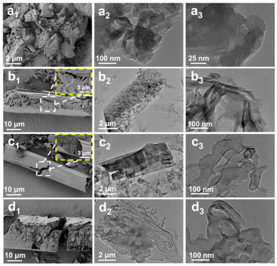
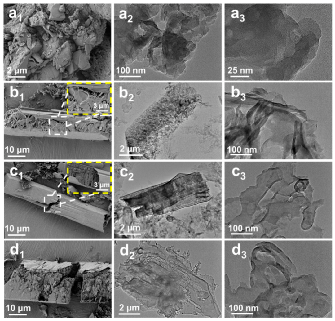
To study the effect of controlling the morphology of g-C3N4 on its performance as an anti-corrosion filler, the corresponding appearance changes were observed using scanning electron microscopy (SEM) at calcination rates of 1, 2, and 3 °C/min and compared with BCN produced by direct calcination. It can be distinctly observed that BCN exhibits an irregular and disordered block structure, accompanied by obvious agglomeration, which is detrimental to the exposure of active sites (Figure 1(a1)). After hydrothermal pretreatment, the precursor exhibits a micro-rod structure with layered aggregation (Figure S1). By controlling different calcination rates, the effects of gas release during thermal polymerization and volume shrinkage of the precursor on the interlayer structure are compared. Surprisingly, RCN-1 displays an obvious layered wrinkled structure during slow heating, significantly increasing the material’s surface area and featuring abundant surface defects and active sites (Figure 1(b1)). In contrast, RCN-2 exhibits a more complete columnar structure compared to RCN-1, but its surface features noticeable damage and cracks (Figure 1(c1)). The layered phenomena within it result in a needle-like, densely packed structure, which increases the total contact surface area while introducing numerous active edge sites and crystal defects. Additionally, the layered structure itself generates interfacial stress, which induces defect formation. Both structures exhibit a regular and orderly layered stacking morphology, providing a high density of active edge sites for efficient charge separation. Furthermore, the oriented stacking structure of RCN-2 can significantly shorten the migration path of charge carriers from the bulk phase to the surface, thereby further promoting the generation of ROS. In comparison, the surface structure of RCN-3 is loose, with obvious layer fractures and debris accumulation, which may be due to rapid heating causing uneven thermal expansion of the material, triggering internal stress and accelerating interlayer fracture and fragmentation (Figure 1(d1)). To further quantify the morphological characteristics of RCN and assess its macroscopic distribution, additional multi-region, multi-magnification SEM images and EDS elemental analysis were performed. As depicted in Figure S2a, at a lower magnification (500×), RCN-2 typically appears as short rod-like structures of varying sizes, with a rough surface and a rich lamellar and porous structure. Statistical analysis estimates that the lengths of these rod-like structures range from 5 to 20 μm, with diameters ranging from 1 to 5 μm. Figure S2b,c represent high-magnification SEM images, clearly demonstrating that the interlayer structure within the rod-like structures is assembled from stacked ultra-thin nanosheet units, with interlayer spacings ranging from 0.05 to 0.1 μm. Furthermore, the corresponding elemental analysis spectrum (EDS) mapping images in Figure S2d show that C, N, and O elements are uniformly distributed across the observed area, consistent with the chemical composition of bulk CN. Meanwhile, the sudden rise in temperature causes gas to be ejected, leaving dense pores inside the material and forming a loose accumulation. Although this structure provides a high specific surface area, excessive porosity will affect the physical barrier function of the coating. To further elucidate the influence of rod-like morphology on graphite-derived carbon nitride, transmission electron microscopy (TEM) was employed. As depicted in Figure 1(a2,a3), the morphology of BCN reveals a distinctly large-block structure, featuring pronounced agglomeration and stacking characteristics within its interior. In this case, the uniform dispersion of BCN filler is significantly compromised, rendering the coating susceptible to permeation by corrosive ions. The subsequent comparison of the RCN regimes revealed an overall morphology exhibiting a fundamental rod-like structure, and TEM observations shown in Figure 1(b2,b3) demonstrated pronounced rod-like characteristics. Notably, the surfaces of RCN-1 displayed numerous loose, porous cavities, with locally thicker lamellar layers exhibiting overlapping and agglomeration phenomena, and a uniform and dense protective layer is thus hindered, resulting in limited corrosion resistance. In contrast, RCN-2 displays a clearly defined, regular rod-like morphology (Figure 1(c2,c3)), featuring congruously stacked, ultra-thin interlayers without discernible agglomerate stacking, which presents favorable interlayer bonding, enabling the formation of a dense, continuous barrier structure within the coating that delays the formation of corrosion pathways. Significantly, pronounced structural fragmentation (Figure 1(d2,d3)) was found within RCN-3, with layered flakes displaying disordered bending and multiple structural defects such as fractures and voids, which allows the coating to be highly susceptible to the formation of micro-corrosion channels, ultimately leading to coating failure.
Figure 1.
SEM images of (a1) BCN, (b1) RCN-1, (c1) RCN-2, and (d1) RCN-3. TEM images of (a2,a3) BCN, (b2,b3) RCN-1, (c2,c3) RCN-2, and (d2,d3) RCN-3.
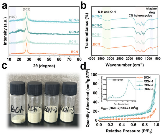
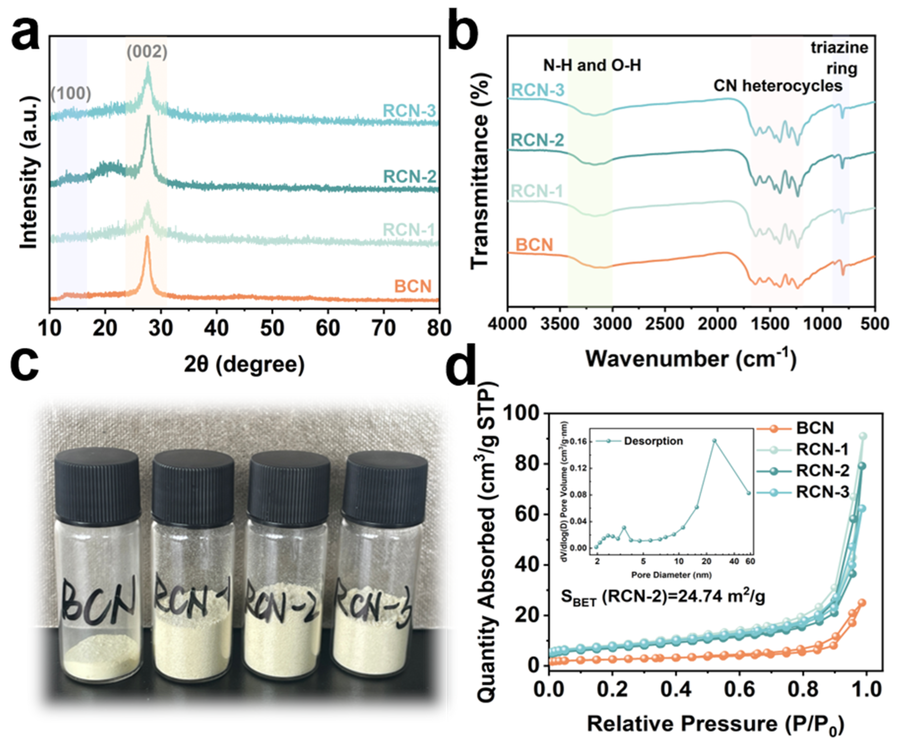
The crystal structures of BCN and RCN-X (X = 1, 2, 3) were investigated using X-ray diffraction analysis (XRD, Figure 2a). All samples exhibit a distinct characteristic peak at 2θ about 27.4°, corresponding to the stacking distance of the interlayer aromatic rings and assigned to the (002) crystal plane [25]. Meanwhile, the presence of a weak characteristic peak of BCN located at 13.1° was observed, attributed to the periodic stacking of the structure of the interlayer heptazine ring (100) [26]. Interestingly, the peak located at the (100) crystal plane in the RCN materials is significantly weaker than that of BCN, suggesting that the periodic structure of the interlayer of RCN samples has been disrupted and allowing for the exposure of more marginal active sites. According to Fourier transform infrared spectroscopy (FT-IR, Figure 2b), the RCN with a rod-like structure has a similar chemical structure to the bulk one. In addition, the presence of distinct broad peaks located at 3000–3500 cm−1 was observed, and this is attributed to the stretching vibrations between the uncondensed terminal amino group (-NH2) or interlayer hydrogen bonds [27]. Furthermore, the strong fluctuation region located between 1200 and 1700 cm−1 is caused by the characteristic stretching vibration of C-N heterocycles, verifying the stability of their short-range structure [28]. The absorption peak at 810 cm−1, on the other hand, corresponds to the breathing vibration mode of the triazine ring [29]. Figure 2c displays a comparison of the optical images of the BCN and RCN series at the same mass (500 mg), and it can be observed that rod-shaped RCN materials exhibit a volume expansion phenomenon, which has a looser morphological surface compared to BCN. In addition, the N2 adsorption–desorption isotherms of RCN exhibit typical type IV isotherms accompanied by the adsorption behavior of H3-type hysteresis loops dominated by slit-like pores (Figure 2d) [30]. Notably, the total void volume of BCN is substantially lower than values observed for the RCN series, which is due to the severe agglomeration present in the bulk structure, whereas the rough layer stacking on the surface of the rod structure exposes more edge-active sites, which in turn leads to considerable increases in both specific surface area and porosity [31]. Among them, RCN-2 displays a higher calculated Brunauer–Emmett–Teller (BET) specific surface area value of about 24.74 m2/g, which is nearly 2.7 times higher compared to BCN (9.016 m2/g, Table S1), while the cumulative pore volume of RCN-2 reaches 0.1407 cm3/g, roughly 3.6 times greater than that of BCN (0.0387 cm3/g), and the average pore diameter is approximately 19.791 nm, confirming a predominantly mesoporous size distribution. Such features originate from interlayer stacking behavior among rod-like units, which facilitates the creation of non-rigid slit-shaped cavities. However, the pore width of RCN-3 declines moderately to 13.998 nm, indicating that an excessively rapid heating rate disturbs the regularity of layer stacking, which aligns with structural deterioration detected via SEM analysis. Meanwhile, the RCN-2 pore size distribution derived from the desorption branch displays a bimodal pattern. A dominant peak centered near 20–25 nm verifies the mesoporous character of the material, arising from oriented stacking of thin sheets that create interlayer pathways. Additionally, a wide subsidiary signal emerged around 3–4 nm. The feature originates from the inherent porosity of g-C3N4, suggesting that the hierarchically porous architecture leads to a notable rise in overall void volume. RCN was analyzed using X-ray photoelectron spectroscopy (XPS), as provided in Figure S3. Figure S3a shows the XPS survey spectra for BCN and RCN-2, both clearly displaying core level peaks for carbon, nitrogen, and oxygen. The high-resolution C 1s spectrum of BCN in Figure S3b presents two distinct peaks, with the intense peak at 288.0 eV being the characteristic main peak of g-C3N4, which is attributed to the N-C=N bond, representing sp2-hybridized carbon atoms within the triazine and heptazine rings constituting the g-C3N4 framework structure [32]. Correspondingly, the N 1s spectrum of BCN in Figure S3c comprises three sub-peaks: The peak at 398.5 eV corresponds to sp2-hybridized nitrogen atoms in the triazine rings, and the peak at 400.1 eV is influenced by the heptazine rings, while the peak at 401.1 eV may be attributed to hydrogen bonding or charged states [33]. Notably, compared to BCN, the hybridization peaks in both the C 1s and N 1s spectra of RCN-2 exhibit a slight negative shift, which indicates that the rod-like structure typically forms a more complete conjugated aromatic system, leading to stronger shielding effects on the core atoms and consequently a slight reduction in binding energy [34,35]. Finally, Figure S3d illustrates the O 1s energy band spectra of BCN and RCN-2, with characteristic oxygen peaks observed at approximately 532.0 eV and 533.2 eV for both materials, which are attributed to oxygenated moieties, including C-O-C and C=O groups, respectively [36]. Comparisons with the above-mentioned XPS data indicate that the micro-rod RCN-2 formed by layer stacking retains the characteristic conjugated ring framework of g-C3N4 [37]. Rather, its unique rod-like morphology endows RCN-2 with superior electronic structure and surface active sites, thereby conferring enhanced application potential in the field of corrosion resistance.
Figure 2.
(a) XRD patterns and (b) FT-IR spectra of BCN and RCN samples. (c) Comparison of optical images of different samples with a mass of 500 mg. (d) N2 adsorption–desorption isotherms of BCN, RCN-1, RCN-2, and RCN-3.
2.2. Coating Surface Characteristics
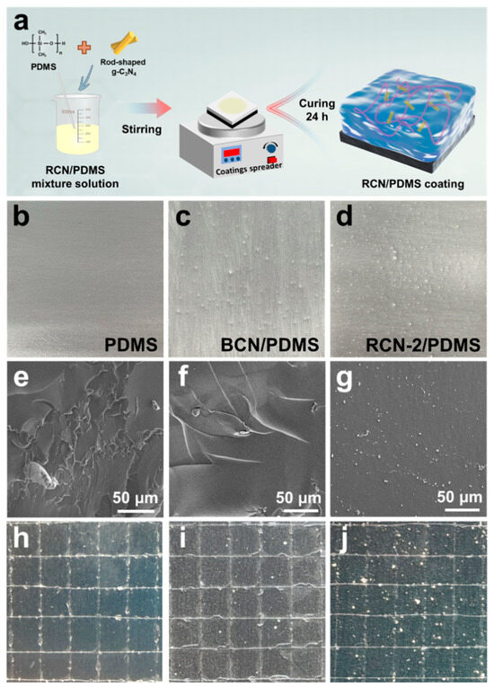
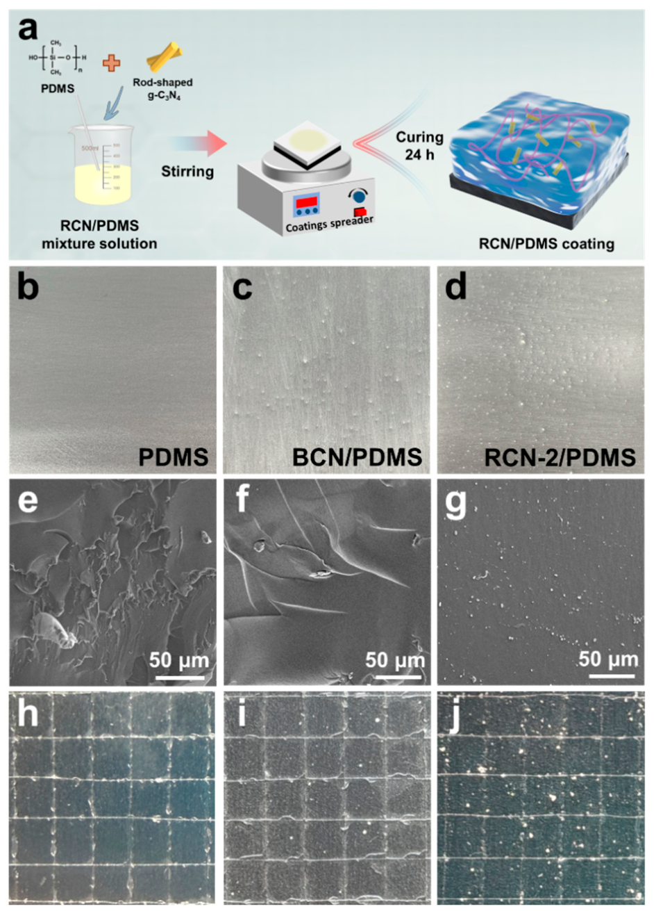
The composite coating was deposited evenly onto the polished Q235 carbon steel substrates via spin coating (Figure 3a), whilst the spin-coated finish is illustrated in Figure 3b–d. Observation of the cross-sectional structure of the coatings can effectively provide information on the internal coating structure of the composite materials, the toughness of the linkage, and the adhesion strength to the substrate. Initially, the cross-sectional morphology of the prepared coatings was compared using SEM (Figure 3e–g). Visible fractures and microcracks are discernible across the cross-section of the PDMS coating. In contrast to bare PDMS, the cross-sectional morphology of BCN/PDMS exhibits no significant alteration, whereas the cross-section of RCN-2/PDMS exhibits a smooth and uniform morphology interspersed with fine particles of the RCN-2 filler. As further evidence, the incorporation of RCN-2 demonstrates its capacity to fill minute cracks and voids within the coating, thereby substantially enhancing the coating’s compactness. Building upon this foundation, scratch testing was employed to evaluate the enhancing effect of as-prepared RCN filler incorporation on the adhesive strength of the coating (Figure 3h–j and Figure S4). In contrast to the pronounced delamination observed in scratches on both pure PDMS and BCN/PDMS coatings, the RCN-2/PDMS coating exhibited superior integrity and smoothness along the scratch edges, which effectively demonstrated the RCN filler’s capacity to enhance the coating’s adhesive properties.
Figure 3.
(a) Schematic for the formation process of RCN/PDMS composite coating on Q235 carbon steel. Optical images of as-prepared coatings: (b) PDMS, (c) BCN/PDMS, and (d) RCN-2/PDMS. Cross-section SEM images of the prepared (e) PDMS, (f) BCN/PDMS, and (g) RCN-2/PDMS coatings. Adhesion strength tests of (h) PDMS, (i) BCN/PDMS, and (j) RCN-2/PDMS coatings.
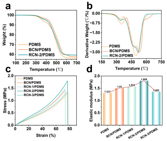
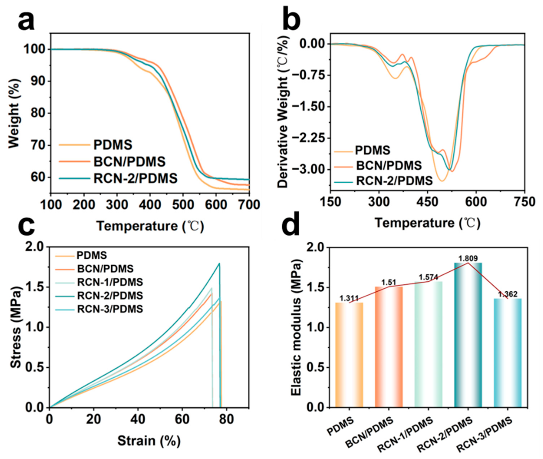
The investigations outlined above encompassed the characterization of the composite coating’s fundamental properties through an intuitive approach, followed by a further in-depth analysis of the structural characteristics within the coatings. First and foremost, the thermodynamic stability of the composite coatings was verified using thermogravimetric analysis (TGA), as illustrated in Figure 4a. For all coatings, there was no obvious mass loss below 350 °C, while the differential thermogravimetric (DTG) analysis curves (Figure 4b) also presented a well-marked mass-loss rate peak at 500 °C, which corresponded to the breakage of the main chain of the PDMS, indicating that the doping of BCN and RCN-2 had no effect on the thermal stability of the composite coatings. The stress–strain curves of the as-prepared coatings are indicated in Figure 4c, and it can be seen that compared to the unmodified pure PDMS coating, the incorporation of fillers enhanced the strain capacity of the coating to a certain extent. Notably, the RCN-2/PDMS composite coating exhibited optimal mechanical properties, achieving a peak value of 1.795 MPa, which may be attributed to the dense interlayer effects of the rod-like structure enhancing physical cross-linking within the coating. Furthermore, a positive influence of the rod-like structure on enhancing the mechanical properties of the coating is confirmed, thereby further extending the service life of the coating. Additionally, the elastic modulus values of all layers are annotated in Figure 4d, which confirms that an elevated elastic modulus manifests macroscopically as enhanced coating hardness and rigidity, thereby conferring superior resistance to deformation, wear resistance, and structural stability. Consequently, monitoring and comparing the Young’s modulus values of the composite coatings revealed a marked increase in the measured values of the RCN-2/PDMS coating (1.809 MPa). The enhanced properties are likely attributable to the highly cross-linked polymer network within the coating and the strong chemical bonds and molecular interactions imparted by the fillers. Such interactions result in a tightly bonded internal surface, thereby reinforcing the barrier effect and anti-permeation characteristics of the anti-corrosion coating, which provides long-term protection for the substrate metal.
Figure 4.
(a) TGA and (b) DTG analysis of PDMS, BCN/PDMS, and RCN-2/PDMS. (c) Stress–strain curves and (d) elastic modulus of PDMS, BCN/PDMS, and RCN-2/PDMS coatings.
2.3. Anti-Corrosion Performance
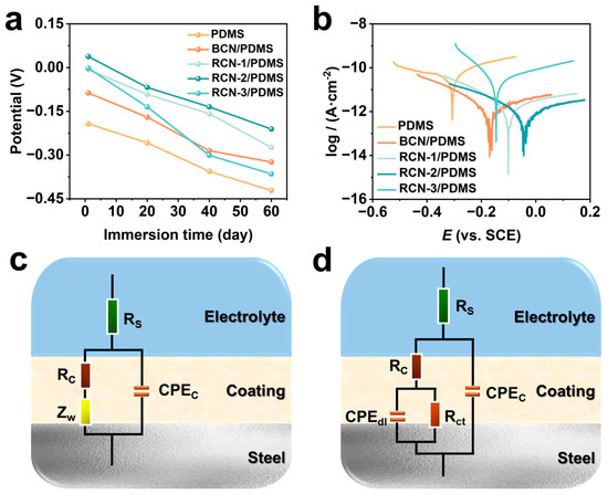
The open circuit potential (OCP) test is one of the most important characterizations for directly observing the corrosion resistance of coatings [38]. Thus, all as-prepared coatings were continuously immersed in a 3.5 wt.% NaCl solution, and the electrochemical properties of the coatings were periodically tested, where higher OCP values indicated stronger corrosion resistance of the coatings. As represented in Figure 5a, the initial OCP value of the pure-phase PDMS coating was about −0.193 V, and the OCP value demonstrated a significant decay with increasing immersion time. OCP values of the BCN/PDMS coatings were both slightly increased compared to the pure PDMS during the test period, but both were much lower than those of the RCN/PDMS coatings. It is noteworthy that the OCP value of the RCN-2/PDMS coating exhibits a significant positive shift and weak attenuation during the corrosion process, and its OCP value still reaches −0.211 V after 60 days. Figure 5b shows the Tafel curves of all composite coatings under dark conditions, where the corrosion kinetics of the coatings can be intuitively assessed from the corrosion current density (Icorr) and corrosion potential (Ecorr) at the intersection of the anodic and cathodic polarization curves [39]. Overall, the rod-shaped modified RCN fillers exhibit superior corrosion resistance, while the RCN-2/PDMS coating demonstrates the best physical barrier effect (Table S2), exhibiting an Icorr as low as 1.03 × 10⁻¹² A·cm−2 and the most positive Ecorr (−0.044 V), with the lowest corrosion rate of 1.20 × 10⁻⁸ mm/year [40]. These results indicate that this material can effectively suppress charge transfer processes and possesses the highest chemical stability. In contrast, the pure PDMS and BCN/PDMS coatings exhibited poorer corrosion resistance. To further validate the continuous protective effect of coatings, electrochemical impedance spectroscopy is often used for corrosion resistance assessment [41]. Nyquist plots were fitted by equivalent circuits (Figure 5c,d), where Rs, Rc, and Rct denote the solution resistance, coating resistance, and charge transfer resistance, respectively, whilst CPEc represents the constant phase element of the coating capacitance, and it is used to describe the dielectric properties and surface roughness of the coating [42]. Correspondingly, CPEdl denotes the double-layer capacitance at the metal–electrolyte interface, and finally, Zw reflects the diffusion behavior of the corrosive medium within the coating or at the interface. Among them, higher values of Rct indicate greater corrosion resistance of the coating, which corresponds to a larger radius of arc tolerance presented in the Nyquist diagram [43].
Figure 5.
(a) OCP values over as-prepared coatings after immersion in 3.5 wt.% NaCl solution for 1, 20, 40, and 60 d. (b) Tafel curves of as-prepared coatings. (c,d) Analog circuitry used in fitting the data.
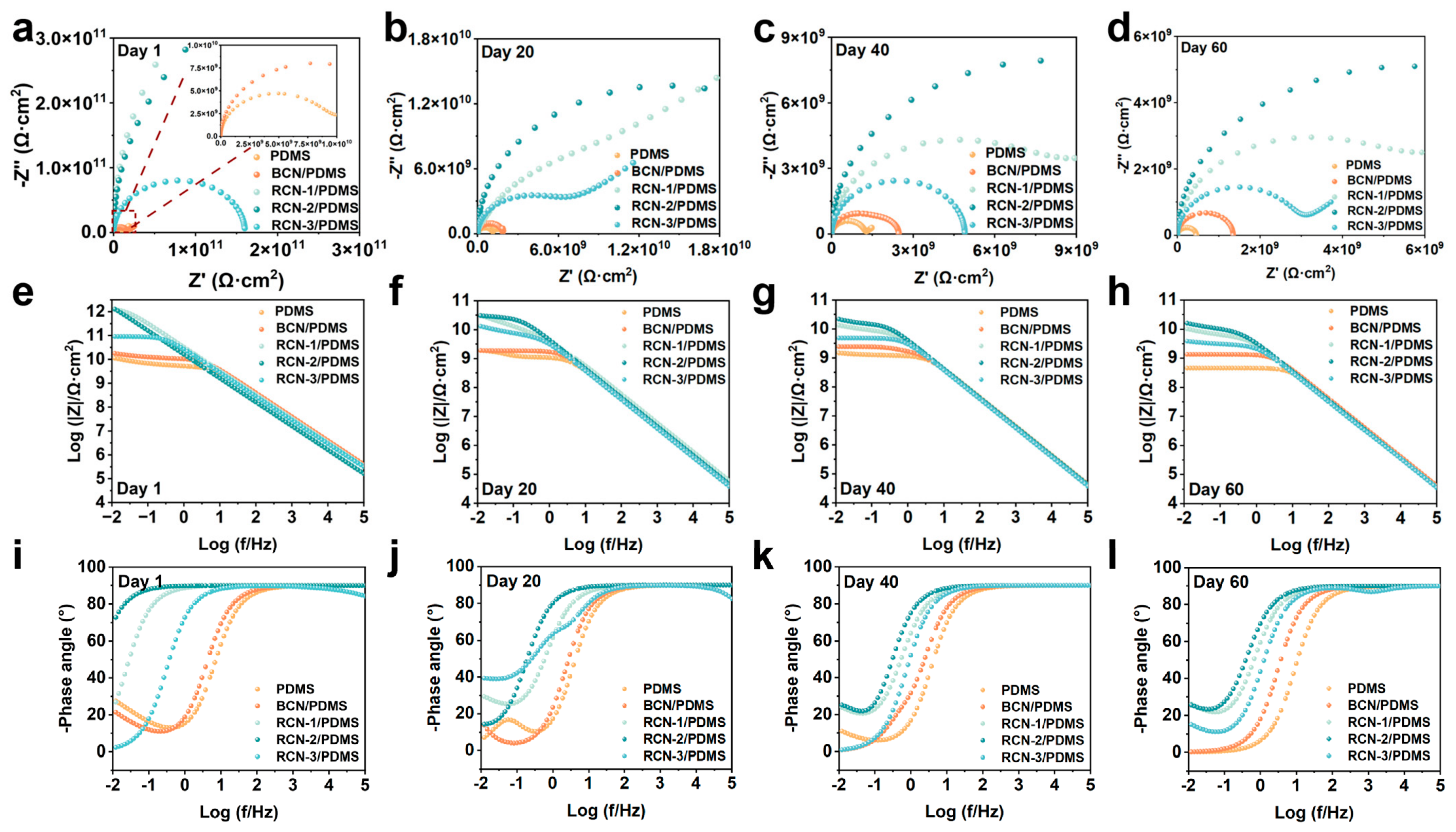
Figure 6a–d disclose the comparative impedance plots of the coatings prepared under different immersion times (Table S3), respectively, and it can be observed that at the early stage of immersion, the impedance arc radius of the RCN-modified composite coating is much higher than that of the pristine PDMS and the BCN/PDMS composite coatings, among which RCN-2/PDMS exhibits the optimum impedance arc radius, and as immersion duration increases, the impedance arc shows a slight reduction in radius, but at 60 days, it still maintains the impedance radius of the RCN-2/PDMS coating at 5.17 × 10⁹ Ω·cm2. This phenomenon indicates that the addition of rod-modified RCN material can effectively hinder the erosion of corrosive ions and enhance the barrier effect of the coating. In addition, Bode plots and phase angle curves of different coatings at corresponding time nodes are presented in Figure 6e–h and Figure 6i–l, respectively. The low-frequency modulus (|Z|0.01 Hz) in the Bode plot is a crucial indicator of the coating’s corrosion resistance, reflecting that corrosion is governed by the ion transport rate [44]. Among them, the low-frequency modulus of RCN-2/PDMS is much higher than that of pure PDMS and BCN/PDMS coatings, indicating the greater charge transfer resistance of the corrosion reaction and stronger corrosion resistance. Correspondingly, the phase angle is close to 90° in the high-frequency region of the phase angle curves, indicating that this region approximates a purely capacitive structure and reveals dense passivation properties or barrier effects. In electrochemical impedance tests, there are several key parameters characterizing the protective properties and failure mechanisms of coatings, of which LogZf=0.01 Hz represents the logarithm of the low-frequency impedance value, which directly reflects the shielding ability of the coating against corrosive media [45]. Comparing the decreasing trend of LogZf=0.01 Hz curves of different coatings in Figure S5a, the decreasing trend of the RCN-2/PDMS coating is gentler, and the value of Zf=0.01 Hz after 60 days is 3.31 × 10⁹ Ω·cm2, which is much higher than that of pure PDMS and BCN/PDMS coatings. Furthermore, the fluctuation of charge transfer resistance Rct verifies the ease of corrosion of the metal substrate [46]. In Figure S5b, the Rct of the RCN-2/PDMS coating always remains at the highest level, which indicates that the corrosion rate of the coating is slow, in agreement with the conclusion of the test of the above parameters. All the above tests confirm that the doping of rod-shaped RCN materials in PDMS coating enhances barrier protection and achieves long-term corrosion resistance.
Figure 6.
(a–d) Nyquist plots for as-prepared coatings in 3.5 wt.% NaCl solution for 1, 20, 40, and 60 days. (e–h) Bode plots and (i–l) phase angles at 1, 20, 40, and 60 days of BCN and RCN-X (X = 1, 2, 3) series.
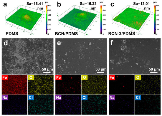
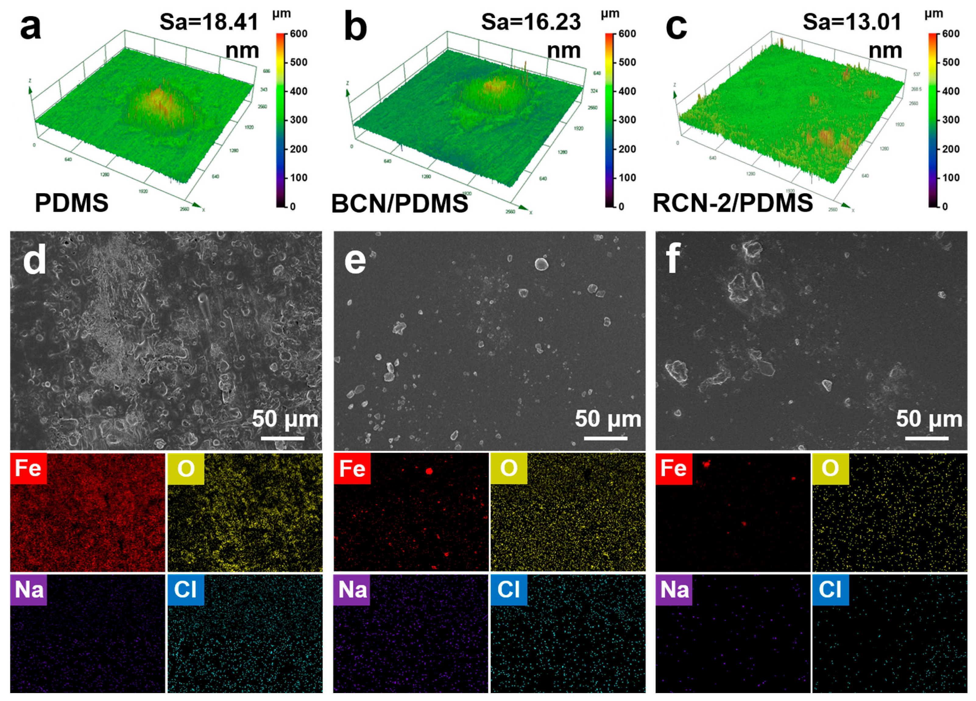
Surface roughness can, to a certain extent, reflect the corrosion resistance of a coating, and generally speaking, the higher the roughness of the surface, the more severe the micro-pitting, cracks, and other corrosion conditions, resulting in weakened penetration and dissolution resistance of the coating, which accelerates the penetration speed of corrosion ions, ultimately leading to accelerated coating failure. Additionally, a rough surface provides numerous attachment sites, facilitating the adhesion and proliferation of fouling organisms on the coating surface. Consequently, low roughness demonstrates that the coating has excellent anti-fouling and anti-corrosion properties. Comparing the surface roughness of pure PDMS, BCN/PDMS, and RCN-2/PDMS coatings before and after immersion in 3.5 wt.% saline solution for 60 days (Figure 7a–c and Figure S6), it is clearly observed that the initial PDMS exhibits a relatively smooth surface due to the low surface energy characteristics of the silane chain segments, with an Sa value of 5.96 nm. After adding BCN and RCN-2 as nanofillers, the surface roughness slightly increased. As pitting and rust spots formed on the coating’s surface, creating microscopic peak-and-valley structures, the roughness of the PDMS and BCN/PDMS coatings increased significantly. In contrast, the roughness of the RCN-2/PDMS coating changed minimally before and after corrosion (increase by about 9.7%), demonstrating excellent structural stability and superior corrosion resistance. Following completion of the 60-day electrochemical test, the corrosion condition of the coating surface in the corrosion area was examined using SEM and energy-dispersive spectroscopy (EDS). As depicted in Figure 7d, the surface beneath the PDMS coating was covered and penetrated by corrosive agents, forming extensive rust and cracks that provided readily accessible pathways for corrosive ions, which resulted in a widespread distribution of Fe and corrosion elements. Under the BCN/PDMS coating, the matrix corrosion was mitigated due to the barrier effect of the BCN filler, though visible pitting corrosion remains (Figure 7e). Remarkably, the surface covered by the RCN-2/PDMS coating exhibits only trace amounts of Fe and corrosion elements, indicating no discernible rusting (Figure 7f), which is attributed to the dense layered structure of the rod-like RCN material forming an insulating barrier between the metal and the corrosive medium; this significantly delays the penetration of corrosive ions, thereby inhibiting the corrosion process and providing a reliable foundation for extending the coating’s lifespan.
Figure 7.
(a–c) Roughness of different coatings after 60 d of immersion in 3.5 wt.% NaCl solution. Surface morphology and energy dispersive spectroscopy analysis of carbon steel coatings after a 60-day test period: (d) PDMS, (e) BCN/PDMS, and (f) RCN-2/PDMS coatings.
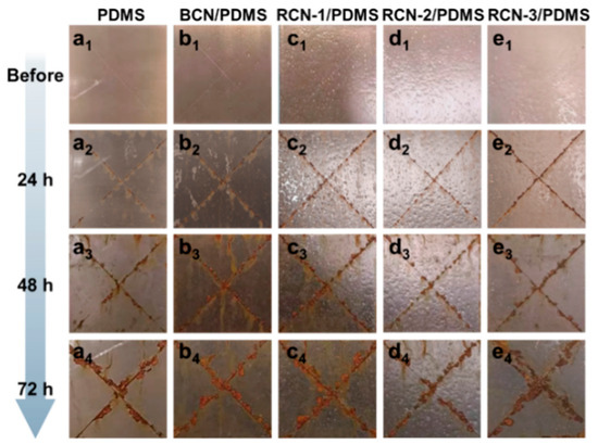
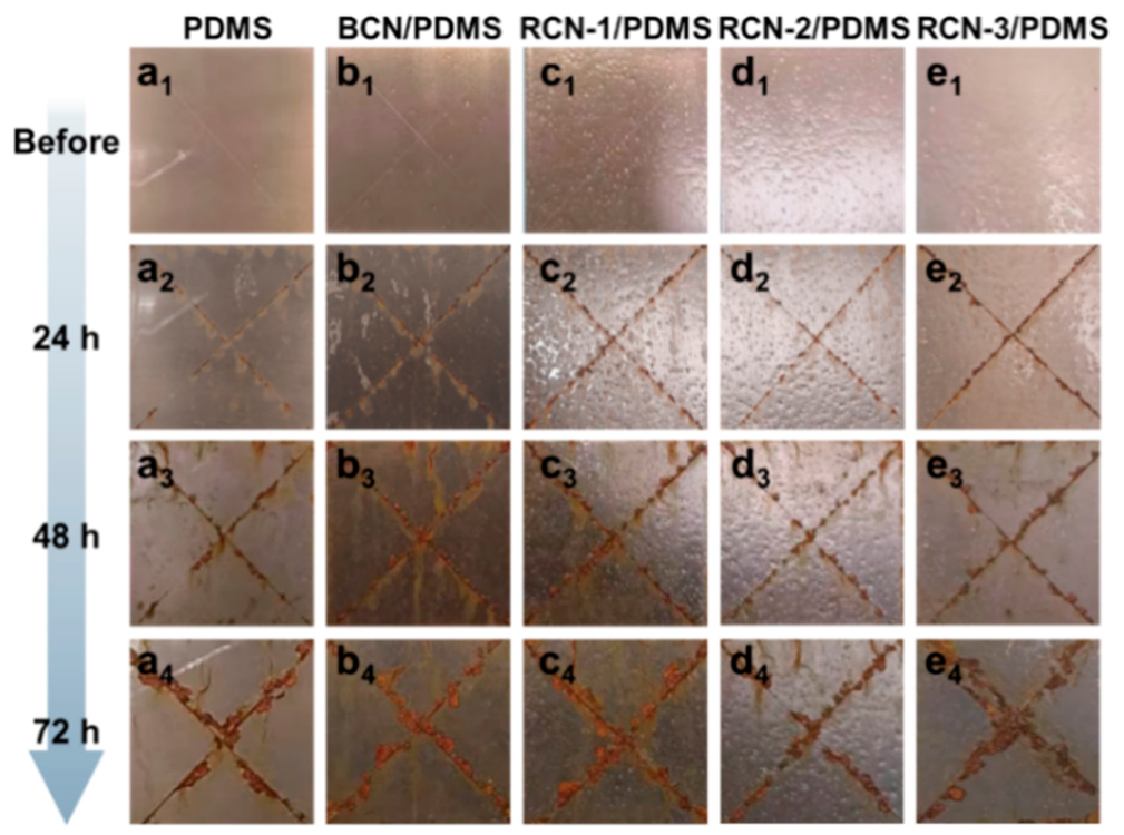
Salt spray testing is a process that simulates a marine or industrial environment with high salt and humidity to accelerate the corrosion process of coatings and thus assess corrosion resistance [47]. The scratched coating specimens were placed in a salt spray chamber for a period of 3 days to monitor the corrosion of the coating surface in real time, and optical images were taken at 24 h intervals for assessing the corrosion resistance of the scratched edges (Figure 8). These images suggest that both pure PDMS and BCN/PDMS specimens expressed numerous rust spots and corrosion traces at the scratches and in the surrounding areas after 72 h. In contrast, the composite coatings with added RCN-2 fillers exhibited relatively weak diffusion of corrosive substances, indicating superior protective performance, likely because the compact rod-like morphology of RCN-2 creates a dielectric barrier layer that separates the metallic substrate from the corrosive electrolyte, effectively blocking the penetration of corrosive ions.
Figure 8.
Digital images of the salt spray texting: (a1,b1,c1,d1,e1) represent pre-test conditions, (a2,b2,c2,d2,e2) represent conditions after 24 h, (a3,b3,c3,d3,e3) denote the state after 48 h and (a4,b4,c4,d4,e4) denote 72 h over as-prepared coatings.
2.4. Microbial Fouling Resistance
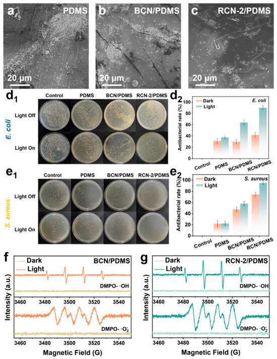
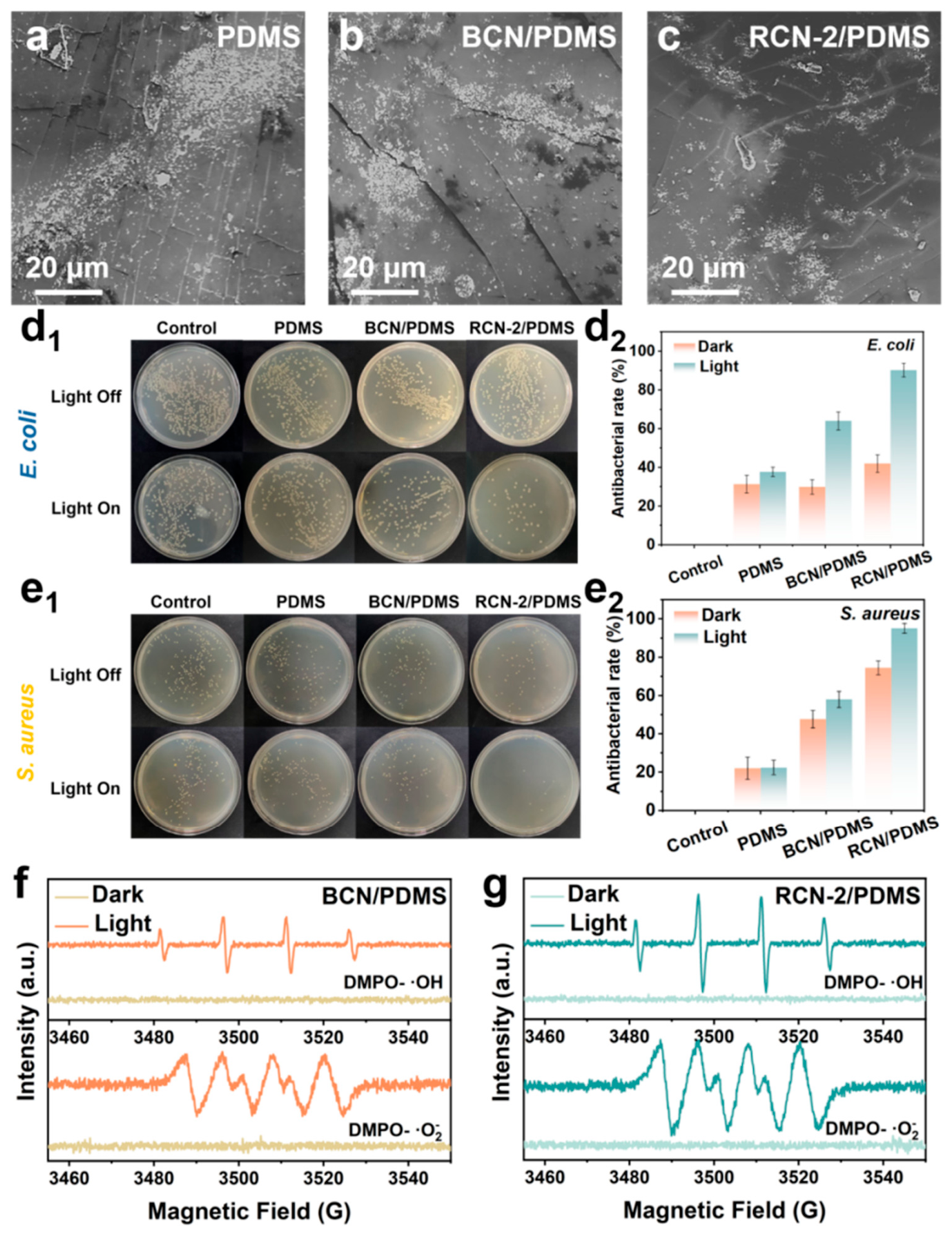
During ship navigation, exposure to algal and microbial fouling environments is inevitable, and microbial adhesion can corrode the hull substrate, significantly reducing the service life of coatings [48]. Accordingly, Chlorella, E. coli, and S. aureus were employed as test organisms to evaluate the coating’s resistance to biofouling. The samples were evaluated under a 300 W Xenon lamp (PLS-SXE300, Beijing Perfect Light Technology Co., Ltd., China), with the vertical distance between the lamp and the sample surface set at a fixed 20 cm to achieve an irradiance of approximately 1500 W/m2. Figure 9a–c demonstrate the anti-fouling efficacy of different coatings against Chlorella attachment. Substantial Chlorella growth was observed on the PDMS coating surface, whereas the BCN/PDMS coating exhibited markedly reduced attachment rates. Significantly, the RCN-2/PDMS surface displayed only minimal fouling, which exhibits superior anti-fouling properties against microorganisms. This is attributed to its capacity to generate a substantial number of electron–hole pairs under illumination and its ability to generate ROS with strong redox properties through reactions with adsorbed O2 and H2O on the coating’s surface [49,50], thereby disrupting the cell walls of Chlorella and inhibiting its growth. To quantitatively assess the antimicrobial performance of the samples, we conducted antimicrobial tests on the coated samples against E. coli and S. aureus. After incubating the samples for 3 h under continuous illumination or in complete darkness, bacterial activity on their surfaces was compared using the plate count method, where the colony counts are shown in Figure 9(d1,e1). Compared with the blank control group, all coated surfaces exhibited varying degrees of reduction in colony counts, which was primarily attributed to the hydrophobic and anti-adhesive properties of the PDMS substrate. A focused comparison of the antibacterial rates under light and dark conditions (Figure 9(d2,e2)) revealed that the antibacterial rates of all samples were higher under light than under dark conditions, clearly confirming that illumination substantially enhanced the antibacterial activity. It is worth noting that under light exposure, the antimicrobial performance of RCN-2/PDMS was significantly enhanced, with the antimicrobial rate against E. coli rising sharply from 42.0% in the dark to 90.3%, whilst the rate against S. aureus increased from 74.4% to 95.1%; this improvement far exceeded the results observed in the control samples, such as pure PDMS or BCN/PDMS. Consequently, a clear correlation can be observed between this phenomenon and the results of electron spin resonance (ESR) testing (Figure 9f,g). The ROS signal from BCN/PDMS is weaker, and the improvement in antibacterial efficacy under illumination is relatively limited. In contrast, under illuminated conditions, RCN-2 exhibits the strongest ROS signal, where enhanced ROS generation is attributed to the abundant edge active sites present in the optimized rod-like structure, facilitating charge separation and migration [51]. Consequently, RCN-2 generates a greater abundance of charge carriers under illumination, leading to efficient ROS production and significantly enhancing the coating’s resistance to biofouling.
Figure 9.
Comparative images of Chlorella adhesion on (a) PDMS, (b) BCN/PDMS, and (c) RCN-2/PDMS coatings. Digital images of antimicrobial testing and the corresponding graphs analyzing quantitative bacterial inhibition rates against (d1,d2) E. coli and (e1,e2) S. aureus for different coatings. ESR spectra of (f) DMPO- ·OH and (g) DMPO- ·O2− for BCN/PDMS and RCN-2/PDMS coatings.
2.5. Optical Properties and Photoelectrochemical Tests
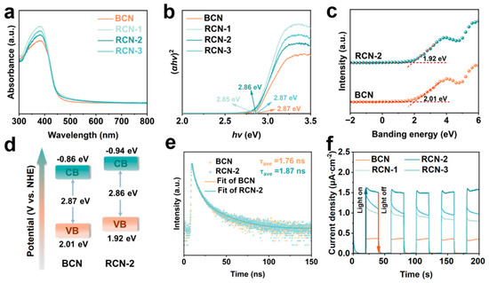
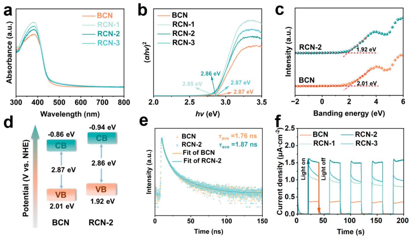
To comprehensively investigate the positive effect of modified RCN fillers on the corrosion resistance of coatings, a series of photoelectrochemical studies were conducted, with particular emphasis on analyzing the influence of their light absorption characteristics and band structure shifts on the redox capabilities of the coating surface. The UV-vis diffuse reflectance spectra of BCN and a series of RCN photocatalytic fillers are presented in Figure 10a. Intuitively, the absorption edge of the prepared RCN samples exhibits a slight red shift [52], which may be attributed to the rod-like structure possessing a larger specific surface area, coupled with the presence of more voids and defect states within the rods. Under illumination, these features induce multiple reflections and scattering effects, effectively extending the transmission path of visible light and thereby enhancing the overall absorbance of RCN materials. Correspondingly, the bandgap widths of the BCN and RCN systems are displayed in Figure 10b. It is noteworthy that the bandgap width of RCN-2 exhibits slight narrowing, signifying enhanced photoexcitation reactivity and increased photogenerated electron production. In contrast, the valence band’s (VB) position was determined by valence band X-ray photoelectron spectroscopy (VB-XPS, Figure 10c), where the VB edge of BCN was found at 2.01 eV and that of RCN-2 was found at 1.92 eV. According to the band energy calculation formula Eg = EVB − ECB [53], the corresponding conduction band (CB) potentials for the BCN and RCN-2 fillers are −0.86 eV and −0.94 eV, respectively, where the final band structure diagram is depicted in Figure 10d. A more negative conduction band position implies that its photo-generated electrons possess a stronger thermodynamic driving force to reduce O2 to ·O2−, thereby enhancing ROS generation. For an in-depth investigation of the effect of the laminated rod structure on the behavior of photogenerated carriers, the photoluminescence (PL, Figure S7) spectra and time-resolved photoluminescence (TRPL, Figure 10e) spectra of BCN and RCN-2 were collected. Crucially, the PL curves directly respond to the distribution of carriers generated by photoexcitation with wavelength, and a significant reduction in PL intensity is observed for RCN-2 compared to BCN, implying that the low-complex photogenerated electrons can be fully utilized for ROS generation [54]. While TRPL records the dynamic decay of fluorescence intensity with time after photoexcitation, the higher average fluorescence lifetime (τ) indicates the prolongation of carrier lifetime, which can continue to participate in the ROS generation process [55]. Comparisons of the above materials reveal that τ increases from 1.76 ns to 1.87 ns, which confirms that the introduction of RCN-2 reduces electron–hole complexation and promotes corrosion inhibition of the metal substrate. Moreover, the photocurrent response curve of the composite material, as revealed in Figure 10f, demonstrates that RCN-2 exhibits a more pronounced photocurrent response characteristic, signifying superior carrier recombination suppression and photogenerated charge separation efficiency [56]. The Mott–Schottky curves for both BCN and RCN-2, displayed in Figure S8a,b, demonstrate characteristic N-type semiconducting behavior. Under illumination, the flat-band potential (Efb) of RCN-2 undergoes a more pronounced negative shift than that of BCN, signifying efficient injection of photo-excited electrons into the conduction band. Additionally, a decrease in curve slope under light exposure indicates an enlargement of the space charge layer’s width, which favors improved charge transport. Furthermore, the donor density (ND) was calculated using the following formula [57,58]:
where e is the elementary charge (1.602 × 10⁻¹⁹ C), is the relative permittivity of the semiconductor, and is the permittivity of vacuum (8.854 × 10⁻¹² F/m). The slope was obtained from the linear region of each M-S plot. Consequently, Figure S8c reveals that the measured ND value of RCN-2 is significantly higher than the carrier concentrations of BCN in both dark and illuminated states. Such a substantial enhancement lays the foundation for excellent charge transfer kinetics. The experimental data presented above demonstrate that the modified RCN materials exhibit superior photocatalytic anti-corrosion properties. Not only does it enhance the utilization of ultraviolet-visible light but it also promotes the separation and transport of photo-generated electron–hole pairs through optimization of the band structure. Hence, it holds promise for providing highly efficient and durable light-driven anti-biofouling protection, while the physical barrier effect ensures corrosion resistance.
Figure 10.
(a) UV–vis diffuse-reflectance spectra and (b) estimated band gap values of as-prepared samples. (c) VB-XPS spectra and (d) band structure diagrams of as-prepared BCN and RCN-2 samples. (e) TRPL spectra of BCN and RCN-2. (f) Photocurrent response curves of BCN and RCN series.
2.6. Mechanism of Anti-Corrosion and Anti-Fouling
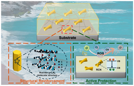
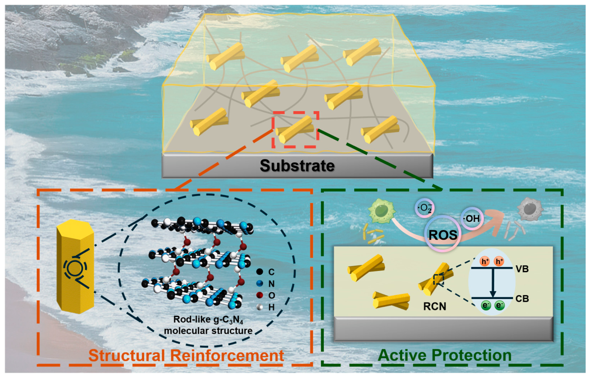
Based on the above analysis, the protection mechanism of the RCN/PDMS composite coatings is demonstrated in Figure 11, attributed to the dense lamellar morphology inside the rod-like structure, which provides greater specific surface contact for the tight composite of nanofillers with the PDMS polymer matrix, while the greater number of contact points greatly improves the mechanical interlocking and adhesion of the coatings with the metal substrate. The highly internally stacked rod-like structure provides a superior physical barrier to metal protection, blocking corrosive media through tortuous pathways and providing greater mechanical stability against damage. More significantly, the highly exposed active edges and defects provide enhanced surface activity and physical protection, which adsorb corrosion factors and enhance mechanical interlocking of interfaces. Meanwhile, RCN shows more active carrier excitation characteristics under light conditions, resulting in more efficient electron–hole pair separation and sustained ROS production, and its strong redox properties directly and efficiently inhibit microbial activity to achieve anti-fouling performance against bacteria and algae. The synergistic effect of the physical barrier and ROS-mediated anti-biofouling provides strong support for the long-lasting protection of metal corrosion.
Figure 11.
Schematic diagram of anti-corrosion and anti-fouling mechanism of RCN/PDMS composite coating.
3. Experimental Section
3.1. Materials
Melamine (C3H6N6) was supplied by Shanghai Macklin Biochemical Co., Ltd. (Shanghai, China). Polydimethylsiloxane (PDMS) and its curing agent (Dow Corning, DC184) were purchased from Guangzhou Weng Jiang Chemical Reagent Co., Ltd. (Guangzhou, China).
3.2. Synthesis of Rod-Shaped g-C3N4
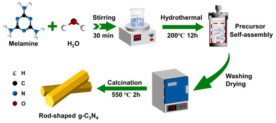
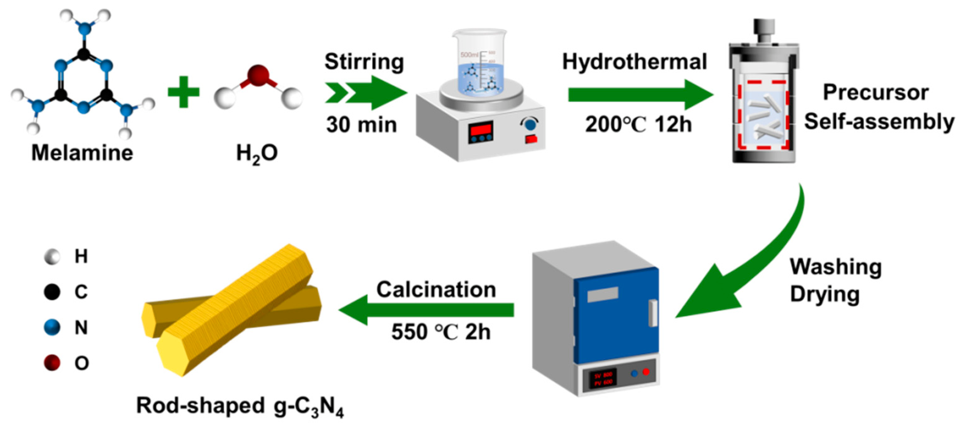
Rod-like g-C3N4 nanostructures were fabricated using a two-step synthesis strategy comprising sequential hydrothermal treatment and pyrolysis, adapted from a previously reported procedure [59], with detailed adjustments to the procedures; a schematic representation of the synthesis is given in Scheme 1. Initially, 2 g of melamine was dispersed in 30 mL of deionized water, followed by continuous magnetic stirring at 600 rpm for 30 min. The resulting mixture was then transferred to a 50 mL Teflon-lined stainless steel autoclave and subjected to hydrothermal treatment at 200 °C for 12 h. After hydrothermal reactions, the resulting precipitate was washed several times with deionized water and finally dried at 60 °C in a vacuum drying oven. The obtained rod-like precursor was subsequently annealed in a muffle furnace under controlled thermal conditions. By regulating the heating rates, rod-like g-C3N4 (abbreviated as RCN-X, X = 1, 2 and 3) was obtained, where X represents heating rates controlled at 1, 2, and 3 °C/min, respectively. All samples were eventually heated to 550 °C in a muffle furnace and maintained isothermally for 120 min. Correspondingly, the control samples, which are designated as bulk g-C3N4 (BCN), were synthesized via direct calcination of melamine under identical thermal processing parameters.
Scheme 1.
Schematic representation of the synthesis of rod-shaped g-C3N4 fillers.
3.3. Preparation of RCN-X/PDMS Hybrid Coatings
The composite coating was fabricated by first homogeneously dispersing the synthesized nanofillers into an anticorrosive polymer matrix (PDMS) and then depositing the resulting mixture onto the surface of a carbon steel substrate. Firstly, after mechanical grinding of the Q235 mild steel surface using 200-grit sandpaper, the steel was treated by anhydrous ethanol immersion treatment, which effectively removed particulate contaminant residues and achieved the cleanliness necessary for subsequent surface characterization. Customarily, 30 mg of the prepared RCN-X was uniformly dispersed in 10 g of PDMS matrix to which an appropriate amount of curing agent was added, where the ratio of PDMS to curing agent was ensured to be 10:1. The resulting mixture was homogenized under ambient conditions, followed by deposition onto the Q235 carbon steel substrate via spin coating, and then, it was cured in an oven at 60 °C for 24 h. The final RCN-X/PDMS composite coatings were obtained after being cured in an oven for 24 h. Correspondingly, the composite coating BCN/PDMS with added BCN powder and the blank PDMS were obtained using the same preparation method.
3.4. Anti-Corrosion Measurements
To simulate the marine corrosion microenvironment, a plastic cup containing 3.5 wt.% NaCl electrolyte was bonded to a Q235 mild steel plate coated with the sample for electrochemical impedance spectroscopy (EIS) analysis. The protocol consisted of several consecutive stages: First, a circular section was excised from the base of a plastic container, which was then securely bonded onto the Q235 steel surface using a two-component epoxy adhesive. Following room-temperature curing for 24 h, 40 mL of the 3.5 wt.% NaCl solution was poured into the cup. The samples were maintained under ambient laboratory conditions for corrosion resistance testing. Full electrochemical monitoring, including open circuit potential (OCP) stabilization, polarization potential (Tafel curves), and Nyquist plot acquisition, was carried out on an electrochemical workstation (CHI 660E) at defined immersion intervals. A three-electrode system consisting of a coated substrate as the working electrode, a saturated calomel reference electrode, and a platinum plate as the counter electrode was tested over a frequency spectrum from 100,000 Hz to 0.01 Hz with a sinusoidal perturbation of 5 mV.
4. Conclusions
This study successfully innovates a novel rod-shaped g-C3N4 nanofiller based on morphology regulation, ultimately producing an RCN/PDMS composite coating that integrates long-term physical barrier corrosion resistance, mechanical reinforcement, and antibacterial fouling prevention capabilities. The oriented RCN formed by this supramolecular self-assembly in the RCN/PDMS composite coating markedly enhanced the coating’s crosslinking properties and effectively suppressed interlayer crack formation and propagation while significantly improving mechanical reinforcement and adhesion characteristics. Correspondingly, EIS and salt spray tests demonstrated that the optimal RCN-2/PDMS coating exhibited markedly enhanced corrosion resistance, with its impedance modulus value (Zf=0.01Hz) remaining as high as 3.31 × 10⁹ Ω·cm2 after 60 days of exposure to a corrosive environment, with no discernible surface rust observed. Furthermore, the coating exhibits heightened reactive oxygen species activity under ultraviolet-visible light irradiation, conferring potent anti-fouling and antibacterial properties, with inhibition rates against E. coli and S. aureus reaching 90.3% and 95.1%, respectively. This work proposes a structurally innovative rod-shaped RCN nanofiller, with the resulting composite coating meeting both long-term anti-corrosion and antibacterial fouling prevention requirements, enabling its broad applicability in industrial infrastructure and marine systems.
Supplementary Materials
The following supporting information can be downloaded at https://www.mdpi.com/article/10.3390/catal16080749/s1. Figure S1. SEM image of rod-shaped precursor after melamine water bath treatment. Figure S2. RCN-2 packing material: (a) SEM image at 500× magnification; (b) SEM image at 2 kX magnification; (c) SEM image at 10 kX magnification. (d) Elemental analysis spectrum (C, N, O) mapping images of the RCN-2. Figure S3. (a) Survey and corresponding high-resolution XPS spectra of (b) C 1s, (c) N 1s and (d) O 1s over BCN and RCN-2 samples. Figure S4. Adhesion strength tests of (a) RCN-1/PDMS and (b) RCN-3/PDMS coatings. Figure S5. (a) Log Zf=0.01 Hz and (b) Log Rct of various coatings during the 60 d of immersion in 3.5 wt.% NaCl solution. Figure S6. Roughness of (a) PDMS, (b) BCN/PDMS and (c) RCN-2/PDMS coatings before 60 d of immersion in 3.5 wt.% NaCl solution. Figure S7. PL spectra of BCN and RCN-X (X=1,2,3) photocatalytic fillers. Figure S8. Comparison of Mott-Schottky curves under illuminated and dark conditions: (a) BCN and (b) RCN-2. (c) Comparison of carrier density estimation in BCN and RCN-2 under light and dark conditions. Table S1. Key parameters for specific surface area test. Table S2. Tafel parameters of all as-prepared composite coatings. Table S3. Summary of chi-squared (χ2) values for all samples at each time point.
Author Contributions
Conceptualization, K.C. and W.S.; methodology, K.C.; software, K.C.; validation, K.C.; formal analysis, K.C.; investigation, K.C.; resources, F.G.; data curation, K.C. and J.S.; writing—original draft preparation, K.C.; writing—review and editing, W.S.; visualization, K.C.; supervision, W.S.; project administration, W.S.; funding acquisition, W.S. All authors have read and agreed to the published version of the manuscript.
Funding
This research was funded by the National Natural Science Foundation of China (No. 22578190), the Science and Technology Planning Social Development Project of Zhenjiang City (No. JC2025004), and the Ministry of Education and Postgraduate Research & Practice Innovation Program of Jiangsu Province (China) (26CXJH7357).
Institutional Review Board Statement
Not applicable.
Informed Consent Statement
Not applicable.
Data Availability Statement
The raw data supporting the conclusions of this article will be made available by the authors upon request.
Conflicts of Interest
The authors declare no conflicts of interest.
References
- Liu, Y.P.; Zhou, Y.Y.; Wang, W.Z.; Tian, L.M.; Zhao, J.; Sun, J.Y. Synergistic damage mechanisms of high-temperature metal corrosion in marine environments: A review. Prog. Org. Coat. 2024, 197, 108765. [Google Scholar] [CrossRef] [Scilit]
- Szabó, S.; Bakos, I. Catalytic processes on the metal corrosion. Korroz. Figy. 2010, 50, 47. [Google Scholar]
- Li, Y.X.; Zhang, Y.Y.; Jungwirth, S.; Seely, N.; Fang, Y.D.; Shi, X.M. Corrosion inhibitors for metals in maintenance equipment: Introduction and recent developments. Corros. Rev. 2014, 32, 163–181. [Google Scholar] [CrossRef] [Scilit]
- Eshaghi, A.; Eshaghi, A. Effect of chromate conversion coatings on the adhesion and corrosion resistance of painted 5083 aluminum alloy. Mater. Sci. 2012, 48, 171–175. [Google Scholar] [CrossRef] [Scilit][Green Version]
- Chavan, T.K.; Sethi, S.K. Eco-friendly self-cleaning coatings: Fundamentals, fabrication, applications, and sustainability. J. Mater. Chem. B 2025, 13, 429–453. [Google Scholar] [CrossRef] [Scilit]
- Li, M.; Lou, T.F.; Li, Q. TiO2 nanoparticles anchored on hollow carbon spheres for enhanced photocatalytic antibacterial. Chin. J. Inorg. Chem. 2023, 39, 1489–1500. [Google Scholar]
- Wu, Y.Y.; Zhang, L.L.; Zhou, Y.Z.; Zhang, L.L.; Li, Y.; Liu, Q.Q.; Hu, J.; Yang, J. Light-induced ZnO/Ag/rGO bactericidal photocatalyst with synergistic effect of sustained release of silver ions and enhanced reactive oxygen species. Chin. J. Catal. 2019, 40, 691–702. [Google Scholar] [CrossRef] [Scilit]
- Tang, H.; Jiang, Q.T.; Xie, R.; Wu, S.W.; Liu, C.; Sun, Q.; Zhang, X.Y.; Jin, Z.Q.; Duan, J.Z.; Hou, B.R. Corrosion and antimicrobial property of TiO2/Cu2O and TiO2/Cu2O@CeO2 micro-arc oxidation coatings on Ti-6Al-4V alloys in natural seawater. J. Cent. South Univ. 2024, 31, 3482–3501. [Google Scholar] [CrossRef] [Scilit]
- Zhang, X.; Xu, B.G.; Yang, P. CuSe nanoplates horizontally implanted on C-doped g-C3N4 nanosheets for H2O splitting and highly selective CH4 conversion. J. Alloys Compd. 2026, 1057, 186771. [Google Scholar] [CrossRef] [Scilit]
- Song, Z.W.; Sun, Y.M.; Wang, J.; Qian, B. Effects of g-C3N4 on the corrosion protection performance of polyvinyl butyral coatings. Prog. Org. Coat. 2024, 187, 108139. [Google Scholar] [CrossRef] [Scilit]
- Chen, C.L.; He, Y.; Xiao, G.Q.; Zhong, F.; Xia, Y.Q.; Wu, Y.Q. Graphic C3N4-assisted dispersion of graphene to improve the corrosion resistance of waterborne epoxy coating. Prog. Org. Coat. 2020, 139, 105448. [Google Scholar] [CrossRef] [Scilit]
- Li, X.; Jiang, Z.Y.; Shi, S.K.; Yuan, Z.M.; Zhu, X.L. Constructing carbon nitride-based homojunction photocatalyst for enhanced hydrogen evolution and selective benzyl alcohol oxidation. J. Photochem. Photobiol. A 2026, 471, 116709. [Google Scholar] [CrossRef] [Scilit]
- Zhang, S.H.; Tang, Y.H.; Wang, X.Y.; Shen, Y.; Zhou, T.; Lu, C.Y.; Guo, F.; Shi, W.L. Photothermal Self-Healing Black g-C3N4 Nanosheet-Based Coatings: A Novel Approach for Enhanced Anticorrosion and Antibiofouling Protection. Small 2025, 22, 2411729. [Google Scholar] [CrossRef] [Scilit]
- Song, P.H.; Yang, P.; Zhang, X. B-derived charge carrier transfer in SnO2/g-C3N4 heterostructures towards enhanced photocatalytic H2O2 production and tetracycline removal. J. Alloys Compd. 2025, 1010, 177659. [Google Scholar] [CrossRef] [Scilit]
- Li, L.L.; Shi, Y.X.; Xu, Z.; Sun, H.R.; Amin, M.D.S.; Yang, X.L.; Guo, F.; Shi, W.L. Environmentally friendly synthesis of oxygen-doped g-C3N4 nanosheets for enhancing photocatalytic corrosion resistance of carbon steel. Prog. Org. Coat. 2022, 163, 106628. [Google Scholar] [CrossRef] [Scilit]
- Zhu, X.L.; Zhou, E.L.; Tai, X.S.; Zong, H.B.; Yi, J.J.; Yuan, Z.M.; Zhao, X.L.; Huang, P.; Xu, H.; Jiang, Z.Y. G-C3N4 S-Scheme Homojunction through Van der Waals Interface Regulation by Intrinsic Polymerization Tailoring for Enhanced Photocatalytic H2 Evolution and CO2 Reduction. Angew. Chem. Int. Ed. 2025, 64, e202425439. [Google Scholar] [CrossRef] [Scilit] [PubMed]
- Sun, Y.; Yuan, S.; Bai, Z.; Liang, B.; Fu, D.; Hu, H.; Pei, L.; Wang, R.; Zhu, Y.; Wang, H. A unique anti-corrosion composite coating with CO2 gas barrier and acid resistance suitable for CCUS environment. Chem. Eng. J. 2023, 472, 144879. [Google Scholar] [CrossRef] [Scilit]
- Yang, G.; Chen, T.; Feng, B.; Weng, J.; Duan, K.; Wang, J.; Lu, X. Improved corrosion resistance and biocompatibility of biodegradable magnesium alloy by coating graphite carbon nitride (g-C3N4). J. Alloys Compd. 2019, 770, 823–830. [Google Scholar] [CrossRef] [Scilit]
- Xia, Y.Q.; He, Y.; Chen, C.L.; Wu, Y.Q.; Zhong, F.; Chen, J.Y. Co-modification of polydopamine and KH560 on g-C3N4 nanosheets for enhancing the corrosion protection property of waterborne epoxy coating. React. Funct. Polym. 2020, 146, 104405. [Google Scholar] [CrossRef] [Scilit]
- Xia, Y.Q.; Zhang, N.G.; Zhou, Z.P.; Chen, C.L.; Wu, Y.Q.; Zhong, F.; Lv, Y.M.; He, Y. Incorporating SiO2 functionalized g-C3N4 sheets to enhance anticorrosion performance of waterborne epoxy. Prog. Org. Coat. 2020, 147, 105768. [Google Scholar] [CrossRef] [Scilit]
- Hu, Z.S.; Han, B.C.; Li, J.H.; Liu, D.; Qi, J. Antibacterial and Anticorrosive Hydrogel Coating Based on Complementary Functions of Sodium Alginate and g-C3N4. Molecules 2024, 29, 4192. [Google Scholar] [CrossRef] [Scilit]
- Zhang, X.; Jiang, S.P. Recent advances in g-C3N4 nanoarchitectonics for efficient photocatalytic H2O2 evolution. Coord. Chem. Rev. 2026, 560, 217889. [Google Scholar] [CrossRef] [Scilit]
- Cuadra, J.G.; Gonçalves, N.P.F.; Tayeb, K.B.; Venâncio, C.; Costa, S.; Lopes, I.; Trindade, T.; Labrincha, J.A.; Novais, R.M. Surface-functionalized g-C3N4/3D-printed alkali-activated materials for the removal of emerging water pollutants. Chem. Eng. J. 2026, 529, 172457. [Google Scholar] [CrossRef] [Scilit]
- Zhang, H.; Yuan, Z.; Zhao, X.; Zhu, X.; Wang, H.; Luo, Y.; Wang, Z.; Jiang, Z. Graphitic carbon nitride photocatalysts for sustainable energy and environmental remediation: Performance optimization and future perspectives. J. Environ. Sci. 2026, 163, 59–75. [Google Scholar] [CrossRef] [Scilit]
- Ding, D.; Hou, Q.K.; Su, Y.G.; Li, Q.Q.; Liu, L.; Jing, J.; Lin, B.; Chen, Y. G-C3N4/TiO2 hybrid film on the metal surface, a cheap and efficient sunlight active photoelectrochemical anticorrosion coating. J. Mater. Sci. Mater. 2019, 30, 12710–12717. [Google Scholar] [CrossRef] [Scilit]
- Yan, H.J.; Yang, H.X. TiO2-g-C3N4 composite materials for photocatalytic H2 evolution under visible light irradiation. J. Alloys Compd. 2011, 509, L26–L29. [Google Scholar] [CrossRef] [Scilit]
- Shi, L.; Si, W.W.; Wang, F.X.; Qi, W. Construction of 2D/2D layered g-C3N4/Bi12O17Cl2 hybrid material with matched energy band structure and its improved photocatalytic performance. RSC Adv. 2018, 8, 24500–24508. [Google Scholar] [CrossRef] [Scilit]
- Bi, X.; Wang, L.Z.; Zhai, D.H.; Wang, L.; Yang, H.; Du, G.H. In-situ synthesis of g-C3N4 with nitrogen vacancy and cyano group via one-pot method for enhanced photocatalytic activity. Sci. Rep. 2025, 15, 19864. [Google Scholar] [CrossRef] [Scilit]
- Tu, D.; Liao, H.W.; Deng, Q.L. Synthesis of BN/g-C3N4 as Visible-light-driven Photocatalysts for Degradation of Different Organic Pollutants. Chem. Sel. 2018, 3, 7170–7177. [Google Scholar] [CrossRef] [Scilit]
- Guo, F.; Chen, Z.; Shi, Y.; Cao, L.; Cheng, X.; Shi, W.; Chen, L.; Lin, X. A ragged porous hollow tubular carbon nitride towards boosting visible-light photocatalytic hydrogen production in water and seawater. Renew. Energy 2022, 188, 1–10. [Google Scholar] [CrossRef] [Scilit]
- Zhang, L.; Lu, X.Y.; Zuo, Y. The Influence of Cathodic Polarization on Performance of Two Epoxy Coatings on Steel. Int. J. Electrochem. Sci. 2014, 9, 6266–6280. [Google Scholar] [CrossRef] [Scilit]
- Ahmed, A.; Niazi, M.B.K.; Jahan, Z.; Samin, G.; Pervaiz, E.; Hussain, A.; Mehran, M.T. Enhancing the Thermal, Mechanical and Swelling Properties of PVA/Starch Nanocomposite Membranes Incorporating g-C3N4. J. Polym. Environ. 2020, 28, 100–115. [Google Scholar] [CrossRef] [Scilit]
- Saini, R.; Farooq, U.; Imam, F. Investigation of the Synergistic Effect of Doping and Composite Formation on Electrochemical OER Performance of g-C3N4 for Sustainable Energy. Energy Fuel 2025, 39, 1327–1340. [Google Scholar] [CrossRef] [Scilit]
- Chen, K.-L.; Yan, J.-Q.; Sun, D.-D.; Zhang, S.-S.; Zhao, Y.-Y.; Huang, J.-H. Electron-donating tris(p-fluorophenyl) phosphine-modified g-C3N4 for photocatalytic hydrogen evolution and p-chlorophenol degradation. Int. J. Hydrogen Energy 2021, 46, 1976–1988. [Google Scholar] [CrossRef] [Scilit]
- Zhang, J.R.; Ma, Y.; Wang, S.Y.; Ding, J.; Gao, B.; Kan, E.; Hua, W. Accurate K-edge X-ray photoelectron and absorption spectra of g-C3N4 nanosheets by first-principles simulations and reinterpretations. Phys. Chem. Chem. Phys. 2019, 21, 22819–22830. [Google Scholar] [CrossRef] [Scilit]
- Huai, X.; Hang, Z.S.; Wang, Z.Z.; Liu, D.L.; Li, Q.Y.; He, Z.; Chen, Y.; Han, X.S. Efficiently enhancing the photocatalytic activity of g-C3N4 by a simple advanced successive activation method. Micro Nano Lett. 2018, 13, 403–406. [Google Scholar] [CrossRef] [Scilit]
- Li, K.; Xiao, T.; Tang, J.; Du, R.; Tu, J.; Xie, F.; Wang, L.; Zhu, H.-Y.; Wu, M. Synergetic non-covalent and covalent functionalization of carbon nitride with donor-acceptor molecules for enhanced photocatalytic hydrogen evolution performance. Appl. Catal. B Environ. Energy 2025, 371, 125201. [Google Scholar] [CrossRef] [Scilit]
- Zhao, M.X.; Yang, X.L.; Li, X.Y.; Tang, Z.; Song, Z.W. Photocathodic protection performance of Ni3S2/g-C3N4 photoanode for 304 stainless steel. J. Electroanal. Chem. 2021, 893, 115324. [Google Scholar] [CrossRef] [Scilit]
- Zuo, S.X.; Chen, Y.; Liu, W.J.; Yao, C.; Li, Y.R.; Ma, J.Q.; Kong, Y.; Mao, H.H.; Li, Z.Y.; Fu, Y.S. Polyaniline/g-C3N4 composites as novel media for anticorrosion coatings. J. Coat. Technol. Res. 2017, 14, 1307–1314. [Google Scholar] [CrossRef] [Scilit]
- Aghaaminiha, M.; Mehrani, R.; Colahan, M.; Brown, B.; Singer, M.; Nesic, S.; Vargas, S.M.; Sharma, S. Machine learning modeling of time-dependent corrosion rates of carbon steel in presence of corrosion inhibitors. Corros. Sci. 2021, 193, 109904. [Google Scholar] [CrossRef] [Scilit]
- Karimi, M.A.; Aghaei, V.H.; Nezhadali, A.; Ajami, N. Investigation of copper corrosion in sodium chloride solution by using a new coating of polystyrene/g-C3N4. J. Mater. Sci. Mater. 2019, 30, 6300–6310. [Google Scholar] [CrossRef] [Scilit]
- Fazli-Shokouhi, S.; Nasirpouri, F.; Ramezanzadeh, B. Smart epoxy coatings reinforced with g-C3N4/Clinoptilolite hybrid nanofillers for corrosion protection and self-healing. J. Mater. Res. Technol. 2025, 38, 5554–5578. [Google Scholar] [CrossRef] [Scilit]
- Chen, X.F.; Wu, X.Y.; Zhang, K.; Long, T. Anticorrosion Improvement of Waterborne Epoxy-Acrylate Coatings by Constructing g-C3N4 Functionalized by Polyaniline-Coated Zinc Phosphate. Ind. Eng. Chem. Res. 2024, 63, 1228–1238. [Google Scholar] [CrossRef] [Scilit]
- Higazy, S.A.; Selim, M.S.; El-Segaey, A.A.; El-Azabawy, O.E. Super-protective graphitic carbon nitride nanocomposites as durable surface coatings. Prog. Org. Coat. 2025, 205, 109283. [Google Scholar] [CrossRef] [Scilit]
- Li, H.; Meng, X.-Z.; Yan, H.-J.; Zheng, R.-C.; Hu, H.-S.; Lei, B.; Zhang, Q.-H.; Wu, L.-K.; Cao, F.-H. Intelligent marine waterborne epoxy coating based on functionalized multiscale nanocomposite: Mechanical enhancement, self-reporting, and active/passive anti-corrosion. J. Mater. Sci. Technol. 2025, 221, 68–83. [Google Scholar] [CrossRef] [Scilit]
- Liu, J.; Tong, Z.; Gao, F.; Wang, J.; Hu, J.; Song, L.; Hou, Y.; Lu, J.; Zhan, X.; Zhang, Q.; et al. Inspired Intelligent Marine Hetero Nanocomposite Coating Based on “Brick&Mortar” Strategy: Anticorrosion Durability and Switchable Antifouling. Adv. Mater. 2024, 36, 2401982. [Google Scholar] [CrossRef] [Scilit]
- Yao, Y.D.; Tang, F.J.; Sun, W. Enhanced corrosion protection of epoxy coating through g-C3N4/g-C3N5 homojunction nanomaterial: Mechanisms and molecular dynamic insights. Constr. Build. Mater. 2025, 481, 141682. [Google Scholar] [CrossRef] [Scilit]
- Liu, W.M.; Zhao, X.R.; Huang, K.F.; Liang, S.M.; Li, J. Construction of ZIF-8@C3N4 hybrid epoxy slippery surface with tailored hierarchical architecture for enhancing antifouling, anticorrosion performance. Colloids Surf. A 2026, 729, 138892. [Google Scholar] [CrossRef] [Scilit]
- Lv, Y.Q.; Zheng, Y.Q.; Zhu, H.L.; Wu, Y.H. Designing a dual-functional material with barrier anti-corrosion and photocatalytic antifouling properties using g-C3N4 nanosheet with ZnO nanoring. J. Mater. Sci. Technol. 2022, 106, 56–69. [Google Scholar] [CrossRef] [Scilit]
- Xie, Z.; Lin, J.; Zhang, W.; Zhang, C.; Yang, W. Enhancing O2 adsorption and activation over porous S-doped g-C3N4 rod toward efficient photocatalytic rhodamine-B degradation. Diam. Relat. Mater. 2024, 141, 110658. [Google Scholar] [CrossRef] [Scilit]
- Huang, J.; Zhong, J.; Wu, H.; Niu, X.; Yu, X.; Li, R.; Chen, J.; Tu, N.; Chen, P.; Sun, J. Accelerated electron transfer in benzene-embedded hollow rod-like g-C3N4 for reversing the thermodynamic bottleneck of oxygen activation: Application in antibiotic wastewater purification. Appl. Surf. Sci. 2026, 747, 167730. [Google Scholar] [CrossRef] [Scilit]
- Guo, Q.Y.; Zhang, Y.H.; Qiu, J.R.; Dong, G.P. Engineering the electronic structure and optical properties of g-C3N4 by non-metal ion doping. J. Mater. Chem. C 2016, 4, 6839–6847. [Google Scholar] [CrossRef] [Scilit]
- Ma, X.G.; Wei, Y.; Wei, Z.; He, H.; Huang, C.Y.; Zhu, Y.F. Probing π-π stacking modulation of g-C3N4/graphene heterojunctions and corresponding role of graphene on photocatalytic activity. J. Colloid Interface Sci. 2017, 508, 274–281. [Google Scholar] [CrossRef] [Scilit]
- Wang, X.L.; Duan, Y.; Zhao, X.L.; Yuan, Z.M.; Zhu, X.L. Insights into atomic level built-in electric field construction via localized graphitization in carbon nitride for enhanced photocatalytic overall water splitting. Mol. Catal. 2025, 573, 114854. [Google Scholar] [CrossRef] [Scilit]
- Babu, P.; Mohanty, S.; Naik, B.; Parida, K. Synergistic Effects of Boron and Sulfur Co-doping into Graphitic Carbon Nitride Framework for Enhanced Photocatalytic Activity in Visible Light Driven Hydrogen Generation. ACS Appl. Energy Mater. 2018, 1, 5936–5947. [Google Scholar] [CrossRef] [Scilit]
- Zhang, X.; Yang, P. Enhanced charge carrier separation and transfer in g-C3N4 and tungsten oxide/sulfide composite photocatalysts. Phys. Chem. Chem. Phys. 2025, 27, 25254–25265. [Google Scholar] [CrossRef] [Scilit]
- Wu, P.; Zhou, T.; Tong, Z.; Xi, F.; Lu, J.; Li, X.; Ma, W.; Li, S.; Yang, X. Balancing charge carrier density and exciton recombination in defective g-C3N4 for efficient photocatalytic hydrogen evolution. Prog. Nat. Sci.-Mater. 2025, 35, 238–244. [Google Scholar] [CrossRef] [Scilit]
- Zhang, C.; Xin, S.; Wang, X.; Huo, S.; Lu, J.; Ma, B.; Ma, X.; Liu, W.; Gao, M.; Xie, H. Photoelectrocatalytic degradation of m-chloronitrobenzene through rGO/g-C3N4/TiO2 nanotube arrays photoelectrode under visible light: Performance, DFT calculation and mechanism. Sep. Purif. Technol. 2022, 302, 121944. [Google Scholar] [CrossRef] [Scilit]
- Xiao, Y.; Tian, G.; Li, W.; Xie, Y.; Jiang, B.; Tian, C.; Zhao, D.; Fu, H. Molecule Self-Assembly Synthesis of Porous Few-Layer Carbon Nitride for Highly Efficient Photoredox Catalysis. J. Am. Chem. Soc. 2019, 141, 2508–2515. [Google Scholar] [CrossRef] [Scilit]
Disclaimer/Publisher’s Note: The statements, opinions and data contained in all publications are solely those of the individual author(s) and contributor(s) and not of MDPI and/or the editor(s). MDPI and/or the editor(s) disclaim responsibility for any injury to people or property resulting from any ideas, methods, instructions or products referred to in the content. |
© 2026 by the authors. Licensee MDPI, Basel, Switzerland. This article is an open access article distributed under the terms and conditions of the Creative Commons Attribution (CC BY) license.