Article

The Structure of Wheel Check Valve Influence on Air Block Phenomenon of Piezoelectric Micro-Pump

School of Mechanical Science and Engineering, Jilin University, No. 5988, Renmin Road, Changchun 130025, China
*
Author to whom correspondence should be addressed.
Micromachines 2015, 6(11), 1745-1754; https://doi.org/10.3390/mi6111452
Submission received: 3 August 2015 / Revised: 29 October 2015 / Accepted: 4 November 2015 / Published: 13 November 2015

Abstract

:
To improve the stability and reliability of the piezoelectric micro-pump, the cause of air block phenomenon is analyzed on the structure of wheel check valve. During the movement of the bubble in the micro-channel, pressure drop occurs, the main factor which influences the bubble going through is opening height of the wheel check valve. Five groups of wheel check valves with different structures are used to test the wheel check valve opening height and air block probability. The experiment results show that reducing the wheel check valve thickness or diameter ratio can both increase the wheel check valve opening height, and decrease the air block probability. Through experiment, the optimum combination of the wheel check valve structure is obtained within the samples: as the thickness is 0.02 mm, the diameter ratio is 1.2, the wheel check valve opening height gets 252 μm, and within the given bubble volume, the air block probability is less than 2%.

1. Introduction

The piezoelectric vibrator can transfer electric energy into mechanical deformation, and the piezoelectric micro-pump (shorten as “micro-pump”) with vibrator has small volume, low power consumption, easy for flow control, etc. The experiment shows that in pure liquid condition or pure air condition, the micro-pump can both work well, however, when micro-pump works in the air-liquid mixed fluids, it easily fails [1]. Two main sources for bubble gets into the pump: The air mixed into the input pipe, e.g., the bubbles caused when adding, changing or sloshing the liquid gets directly into the pump channel; the micro-air mass dissolved in liquid changes into micro-bubbles under the changes of the ambient temperature or the alternating pressure, and the micro-bubbles grow, combine to obvious volume bubbles. The failure caused by bubbles show as the bubbles get into the pump channel, the channel is blocked in random, the piezoelectric vibrator can vibrate normally, but the pump can not convey fluid any more. The channel block caused by bubbles is normally called “air block”, which has bad influences on the stability and reliability of the output capacity of the pump, and greatly restricts the application of the pump. In recent years, researchers domestic and aboard gradually recognize the bad effects on the pump performance from bubbles, and the bubble exclusion capacity is set as one important factor for pump design [2,3,4,5]. To increase the bubble exclusion capacity of the pump, different measures was selected, e.g., reducing the dead volume, increasing the stroke of micro actuators [6,7,8,9,10], increasing the number of the vibrator [11,12], etc. which greatly increase the pump self absorption pressure and flow rate, in some extent, the bubble exclusion capacity is also improved. However, even if the pump works far less than its self absorption pressure loading range, the air block still exists. The micro-pump manufactured in this paper is used as the experimental object, during normal working process, the flow and output pressure are 10 mL/min and 15 kPa, when air block happens, there is no flow or output pressure, the micro-pump can not work. The existence of the air block phenomenon hinders the pump application and extension, to avoid the air block is the necessity to improve the stability and reliability of the pump.
The air block phenomenon of micro-pump is investigated in this paper, and the mechanism is mainly described, through fluid mechanics and structure mechanics, the relationship between the wheel check valve structure and the air block phenomenon is analyzed. Based on theoretical analysis results, measurements on reducing air block probability are presented.

2. Air Block Phenomenon

Figure 1a shows the micro-pump structure, which consists of cover plate, piezoelectric vibrator, inlet wheel check valve (shorten as valve), outlet valve, pump body, inlet pipe and outlet pipe. The vibrator, pump body and the two valves build up a closed chamber. When the vibrator has reciprocating vibration, the pump chamber volume changes as well, the two valves open and close periodically, the sucking process and discharging process are created. During sucking process, the chamber volume increases, the inlet valve opens, outlet valve closes, the fluid gets into the chamber; during the discharging process, the chamber volume decreases, the outlet valve opens, inlet valve closes, the fluid gets out of the chamber. Cycle by cycle, the flow reaches in one direction [4,13,14,15,16].
Figure 1. Micro-pump for experiment. (a) Micro-pump structure; (b) Micro-pump used in the experiment.
Micromachines 06 01452 g001
As the bubbles get into the pump chamber, because of the tiny and complicated structure of the channel in the valve, the bubbles easily stay around valve, as shown in Figure 2, white mark is made to recognize the bubble boundary. At this time, the output flow of the pump reduces sharply, unless the bubble gets through the channel and excluded. However, if the bubble is not excluded, and the external load increases slightly, the flow output of the pump will be easily stopped, this is how the air block happens. When the working medium is pure air, the loading capacity of the pump in this paper is 5 kPa, it reaches 25 kPa as the working medium is pure liquid. However, even if the load is below 5 kPa, with air-liquid mixture as the working medium, the air block may happen. The experiment shows that as air block happens, in most cases, the bubbles are either around inlet valve or outlet valve. As air block happens, even with a positive pressure working in the pump inlet valve, as shown in Figure 3, the air block can not be solved, unless the positive pressure is high enough. Based on this condition, the air block is caused by the combination of bubble, liquid and check valve.
Figure 2. Bubble stayed around inlet valve.
Micromachines 06 01452 g002
Figure 3. Air block under positive pressure.
Micromachines 06 01452 g003

3. Valve Structure and Bubble Flow

3.1. The Pressure Drop from Bubble Flow in the Valve

As shown in Figure 4, when the pump works, the check valve vibrates periodically, the maximum distance between valve plate and the base is called valve opening height, shown with Hv. The valve plate thickness used in the paper is 100–300 μm, which is in accordance with micro-channel definition. As the bubbles moves in the micro-channel, the pressure drop occurs, and the pressure drop is directly related with the section of the micro-channel [17,18,19,20]. The micro-channel between inlet/outlet and the valves, the valve opening height Hv influence the micro-channel section size dynamically, which also influence the bubble flow resistance. When the valve plate opens, the bubble gets through between valve plate and the base into the pump chamber, as shown in Figure 4. Based on the micro-pump working principle, there are two phases, sucking phase and discharging phase. During sucking phase, inlet valve opens, outlet valve closes. In discharging phase, inlet valve and outlet valve do the opposite compared with sucking phase. Therefore, during the two phases, there are pressure drops Δ P B O and Δ P B I separately produced when the bubble goes through inlet valve and outlet valve, and they are individual. Meanwhile, since the structures of inlet valve and outlet valve are the same, the pressure drop produced in sucking phase is also produced in discharging phase. In this paper, the inlet valve in sucking process is selected for analysis.
Figure 4. Bubble through valve plate.
Micromachines 06 01452 g004
The valve opening height Hv in this paper is 100–300 μm, as the bubble gets through, taking the valve as a rectangular section pipe with the width Hv and length πDH which is inlet pipe circumference. Wong et al. [17] show that in a polygonal capillary, a long bubble acts as a leaky piston, the liquid can either push the bubble (plug flow) or bypass the bubble through corner channels (corner flow). When the bubble goes through the valve opening gap, as is shown in Figure 4, since there is no corner area, when the bubble goes through the gap, there is only plug flow. Wong points out the plug flow obeys the pressure-velocity relation of the bubble because the pressure driving the plug flow is dissipated predominantly by the liquid films lubricating the bubble, as in circular capillaries. Suppose the bubble disperses in the radial direction homogeneously, based on [20], the pressure drop occurs when the bubble goes through inlet valve opening gap is:
Δ P B I = 7.16 ( 3 μ L u B σ ) 2 3 ( σ d )
where μL is dynamic viscosity of water, u B is mean velocity of bubble, σ is surface tension, d is the equivalent diameter of the capillary, then:
d = H v
The valve opening height = 100~300 μm. Under 25 °C, μ L = 0.00089  N s / m 2 , σ = 0.0072 N / m [21], then Equation (1) is changed to:
Δ P B I = 0.05733 ( u B ) 2 3 / H v
Supposing the bubble has the same speed with the liquid, and the outflow of the pump is stable, when the outflow of the pump keeps the same, if the valve opening height increases, u B will decreases, the pressure drop Δ P B I will decrease.
Δ P Δ P B I  or  Δ P Δ P B O
Δ P is the driving pressure,the channel is easily blocked by the bubble. Based on Equation (3) and [20], when the valve opening height increases, the pressure drop Δ P B I from the bubble will decrease, then it’s easy for the bubble to get through, which can reduce the air block probability in the pump. Therefore, the valve opening height is a main factor in air block, changing the valve opening height through optimizing the valve structure is able to reduce air block probability.

3.2. Valve Opening Height and Equivalent Stiffness

The valve opening height [22]:
H v = Δ P v A v k v
where k v is the valve equivalent stiffness, Δ P v is the pressure drop between the two sides of the valve, A v is the valve effective cross section area. From Equation (5) when the pressure drop keeps the same, the smaller k v , the bigger the valve opening height .The valve structure is shown in Figure 5a in the paper, the valve is modeled as a cantilever beam, as shown in Figure 5b, the equivalent stiffness [22]:
k v = b t 3 E 4 n l 3
where E is the elastic modulus of the material, l is the length of the beam, n is the number of the beam, b is the width, t is the thickness. When the cantilever beam structure of the valve stays the same, E is 128 GPa, n is 3, l is 13.00 mm, b is 2.50 mm, A v = π × ( D H 2 ) 2 = 0.79   mm 2 , take Equation (6) into Equation (5):
H v = 4 Δ P v A v n l 3 b t 3 E = ( 6.47 × 10 20 ) Δ P v t 3
From Equation (7), the cube of the thickness t is inversely proportional to the opening height Hv, when the valve thickness t reduces, the valve opening height Hv will increase.
Figure 5. Valve bending cantilever beam. (a) Structure; (b) Simplified force analysis.
Micromachines 06 01452 g005

3.3. The Valve Opening Height and Diameter Ratio

To ensure the sealing performance, the valve plate diameter Dv must be bigger than the base hole diameter Dh. When the medium is pure air, the diameter ratio R D slightly influences the valve opening height Hv, where R D = D v D h . When the medium is pure liquid, since the valve plate is bigger than the base hole, there is gap existing between the area of the valve plate in contact with the base and the base itself, and there is big flow resistance in the gap area, the diameter ratio R D has big influence on the valve opening height Hv [22]. When the medium is the mixture of air and liquid, the diameter ratio R D mainly influences the valve opening height Hv by capillarity, as shown in Figure 6, supposing there are bubbles in both sides of the valve plate, and there is liquid membrane in the gap between the valve plate and the base, then the opening condition of the valve is
Figure 6. Opening and force for the inlet valve.
Micromachines 06 01452 g006
π D h 2 4 ( P 1 P 2 ) π ( D v 2 4 D h 2 4 ) P 2 + F L
where Dv is the valve plate diameter, Dh is the base hole diameter, P1 is the inlet pressure, P2 is the pressure in the pump channel, FL is the capillary force between the valve plate and the base. The capillary force [23]:
F L = π ( D v 2 D h 2 ) γ L ( cosθ 1 cosθ 2 ) 4 H G
where θ1 and θ2 are the contact angel between the liquid and the lower side of the valve plate and upper side of the base, H G is the gap height between the valve plate and the base, γ L liquid surface tension. Combining Equations (8) and (9), the valve plate opening condition is
( P 1 P 2 ) ( ( D v D h ) 2 1 ) [ P 2 + γ L ( cosθ 1 cosθ 2 ) H G ]
When the assembly process is consistent, H G keeps the same, when the materials of the valve plate and the base keep no change, the liquid keeps the same, there is no change in  γ L , θ 1 , θ 2 , from [23], as inorganic salt and alkali are added into the water, the γ L of the water increases as the solute concentration increases, as the organic acid and alcohol are added into the water, the γ L of the water decreases as the solute concentration increases. Because of the limitation of the paper length, the surface tensions of different working media are not measured and investigated, but only the pure water. When the pressures in both sides of the valve plate P1, P2 keep the same, Equation (10) can be simplified as:
Δ P v A × ( R D 2 1 )
Δ P v is the pressure difference from the micro-pump, A is constant, RD is diameter ratio. From Equation (11), the smaller the diameter ratio RD is, the easier the valve plate can open, the valve opening height H v will increase.

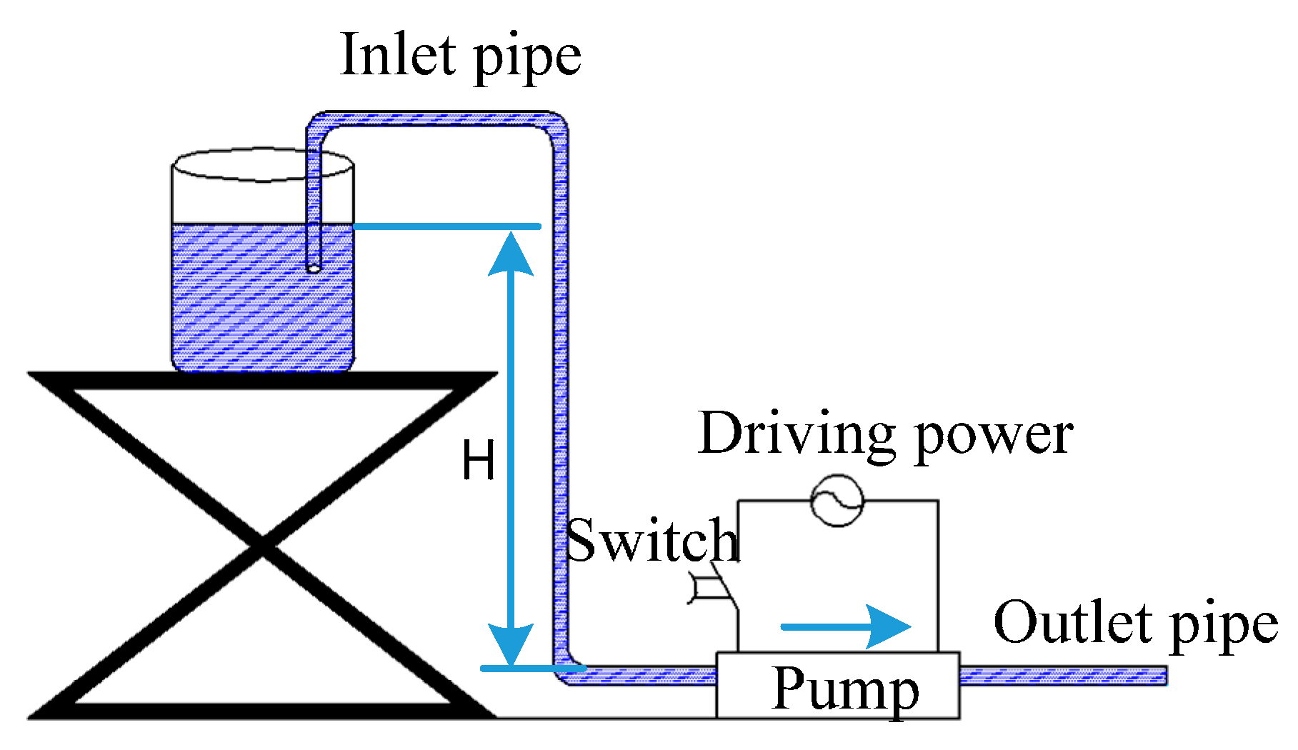
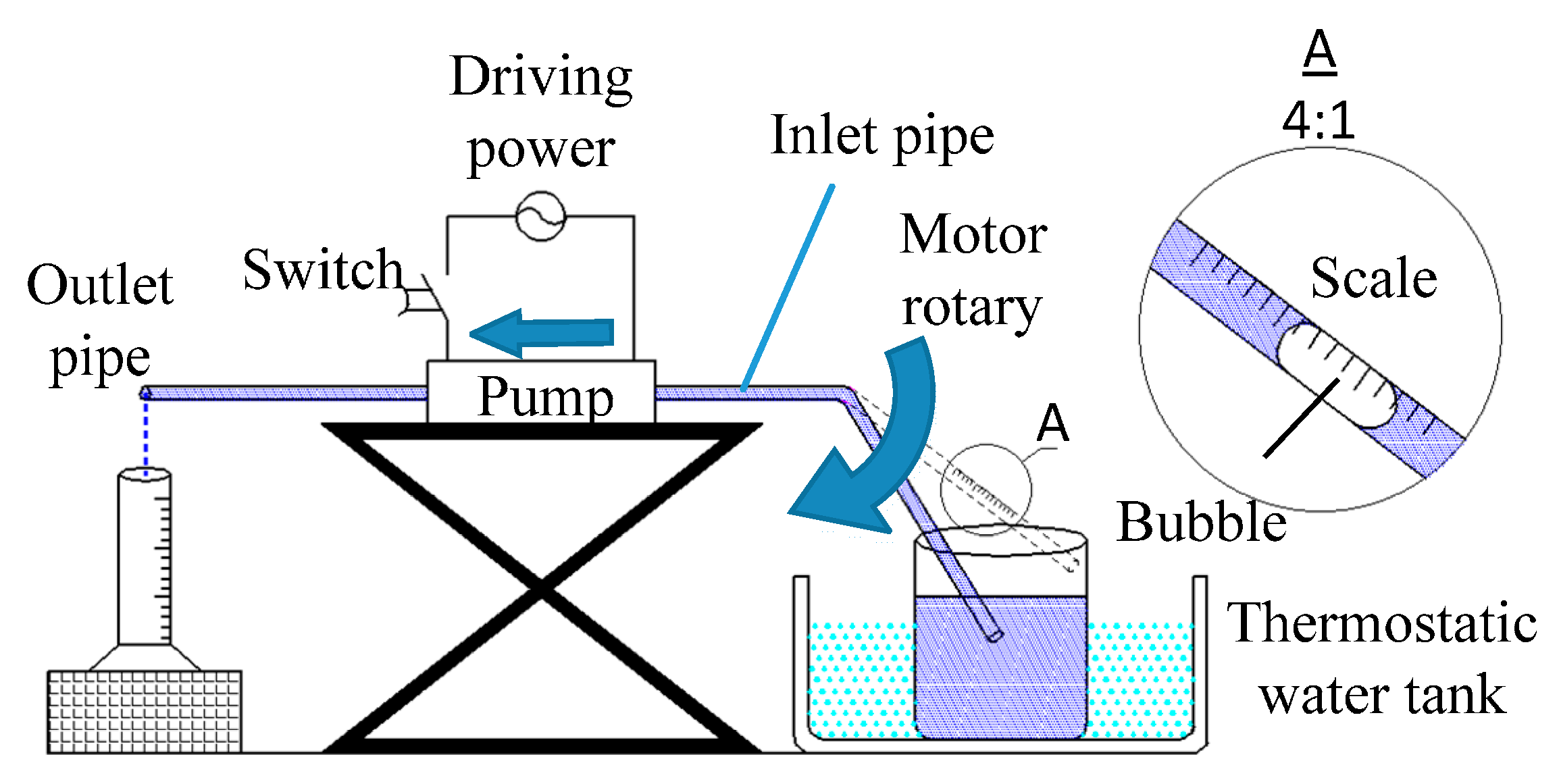
4. Experiment and Discussion

From the theoretical analysis in Section 3, reducing the valve equivalent stiffness, or the diameter ratio can both increase the valve opening height to decrease the micro-pump air block resistance. To validate the theoretical analysis, the valves with different thicknesses t and diameters Dv are made to change the valve equivalent stiffness and diameter ratio. Laser micrometer is used to measure the valve opening height Hv, meanwhile, the air block probability is compared. The parameters of the micro-pump are shown in Table 1.
Table 1. The parameter of the micro-pump.
TypeValue and Material
Pump size27 mm × 27 mm × 7 mm
Pump MaterialPMMA (Polymethylmethacrylate)
Base plate outer diameter of the vibratorΦ20 mm
Base plate thickness of the vibrator0.2 mm
Base hole diameter DhΦ1 mm
Valve diameter DvΦ1.2, Φ1.4, Φ 1.6, Φ1.8, Φ2.0 mm
The connecting pipe materialrubber
The connecting pipe diameterΦ4 mm (outer), Φ2 mm (inner)
Check valve structurewheel type
Check valve Materialberyllium bronze
Check valve Thickness t20, 30, 40, 50, 60 μm
Power110 V, 50 Hz, square wave
To obtain bubbles precisely, manually adding bubble device is made, as shown in Figure 7 and Figure 8, with PLC (Programmable Logical Controller), the device can control the step motor to run according to a certain angel, which can push the inlet pipe to pull in and out of the liquid periodically, the bubbles can get into the pump regularly. To control the volume of the bubbles, the time staying in the air for the inlet pipe is set up. The partial enlarged drawing in Figure 8 is the graduated scale printed in the inlet pipe to measure the bubble volume.
When the device starts working, after the first bubble is excluded from the outlet pipe, the next bubble is allowed to get into the pump, until the air block occurring, stop inserting a new bubble, under big external pressure in the inlet pipe, the bubble is taken out to eliminate the air block, and fill the channel with liquid again to restart the testing. Record air block times NBL through a certain bubble quantity in the channel. In the experiment, one hundred bubbles are sets up to get into the channel, check the air block average number for five times. Air block probability is defined as NBL/100. To make the comparison more effective, three different kinds of bubble volumes are used 0.2, 0.4 and 0.6 mL.
Figure 7. Manually adding bubble device.
Micromachines 06 01452 g007
Figure 8. Micro-pump air block experiment device.
Micromachines 06 01452 g008
Laser with wave length 355 nm is used to manufacture the valve, the valve thickness t = 40 μm. The diameter ratios RD are 1.2, 1.4, 1.6, 1.8 and 2.0 separately. The valve opening height H v and air block times NBL in the experiment is shown in Figure 9 and Figure 10.
With the diameter ratio RD increasing, the valve opening height Hv is reducing gradually, which is consistent with Equation (7). The concept of equivalent stiffness is used in Equation (7) to describe the movement of the valve plate, and Δ P v is supposed to be the same, therefore, there is a certain deviation between the prediction from Equation (7) and the real condition shown in Figure 10, but from Figure 10, we can see Equation (7) can still show the relationship well between H v and t. Also, in the samples, increase the bubble volume, the occurrence of air block is more frequent. In this experiment, diameter ratio RD = 1.2 is selected as the most optimized one, since diameter ratio RD which is below 1.2 makes the assembly of the valve very difficult, and the sealing effect is also not ensured, which makes bad influence to the pump performance, so diameter ratio RD below 1.2 is not selected in the experiment.
As RD = 1.2, testing on valves with different thickness t = 20, 30, 40, 50 and 60 μm were carried out. The results are shown in Figure 11 and Figure 12.
From Figure 11 and Figure 12 with the thickness reduction of the valve plate, the valve opening height Hv increases, and air block times NBL reduces, which is in accordance with Section 3. Within the samples, the most optimized valve thickness is 20 μm. The thickness t below 20 μm is not selected in the experiment, because too small thickness can reduce the micro-pump best working frequency dramatically, and more sensitive to the frequency, and furthermore, influence the comparison.
In the experiment, the best combination for the valve: diameter ratio is 1.2, thickness is 20 μm. With this combination for the micro-pump prototype, the measured valve opening height is 252 μm, and when the bubble volumes are 0.2, 0.4 and 0.6 mL, the air block probability are 0%, 1% and 2%.
Figure 9. The relationship between diameter ratio RD and air block times NBL, when Thickness of the check valve t = 40 μm.
Micromachines 06 01452 g009
Figure 10. The relationship between diameter ratio RD and the valve opening height Hv, when Thickness of the check valve t = 40 μm.
Micromachines 06 01452 g010
Figure 11. The relationship between thickness t and air block times NBL, when RD = 1.2.
Micromachines 06 01452 g011
Figure 12. The relationship between thickness t and valve opening height Hv, when RD = 1.2.
Micromachines 06 01452 g012

5. Conclusions

  • Air block is caused by the combination of bubble, liquid and check valve.
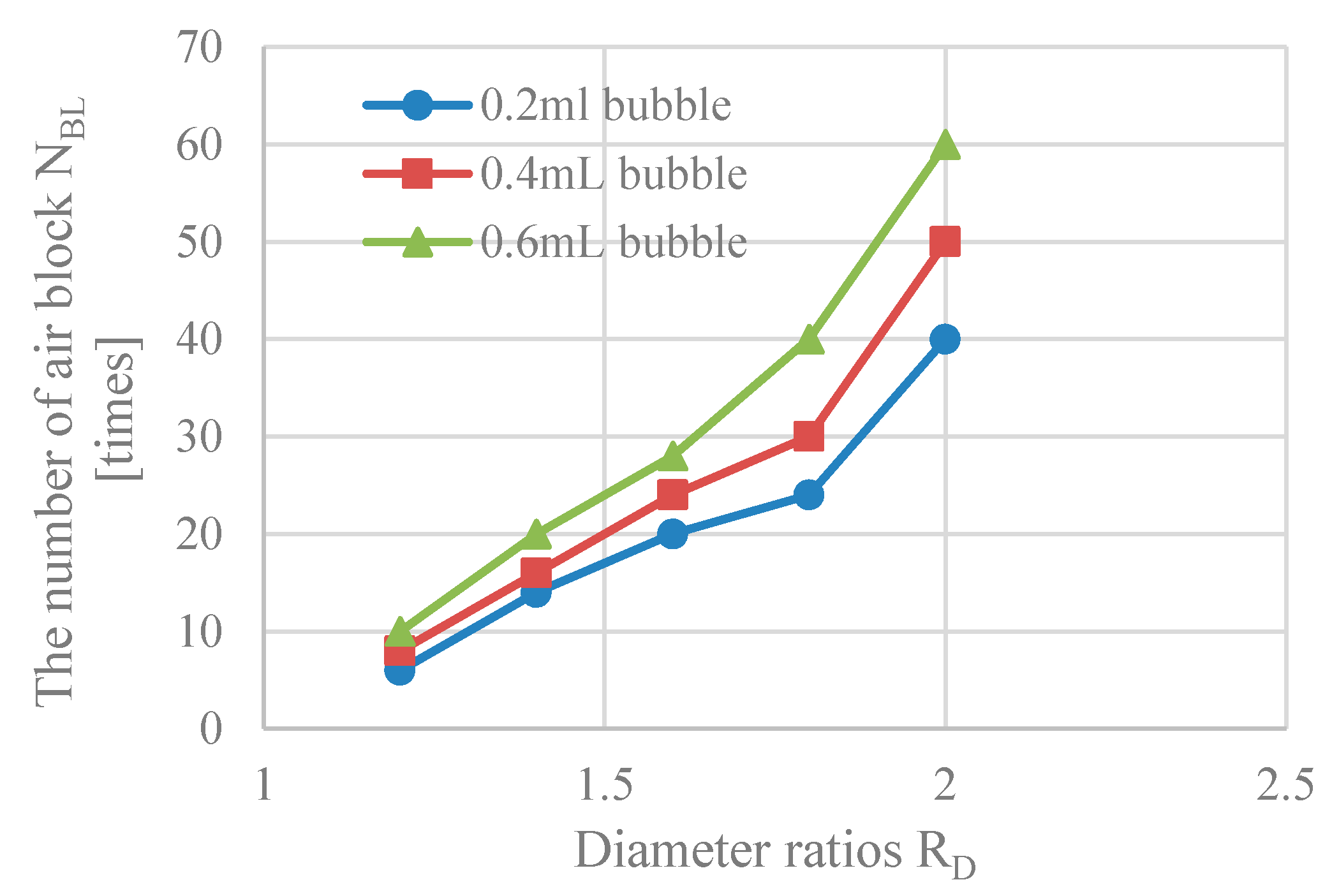
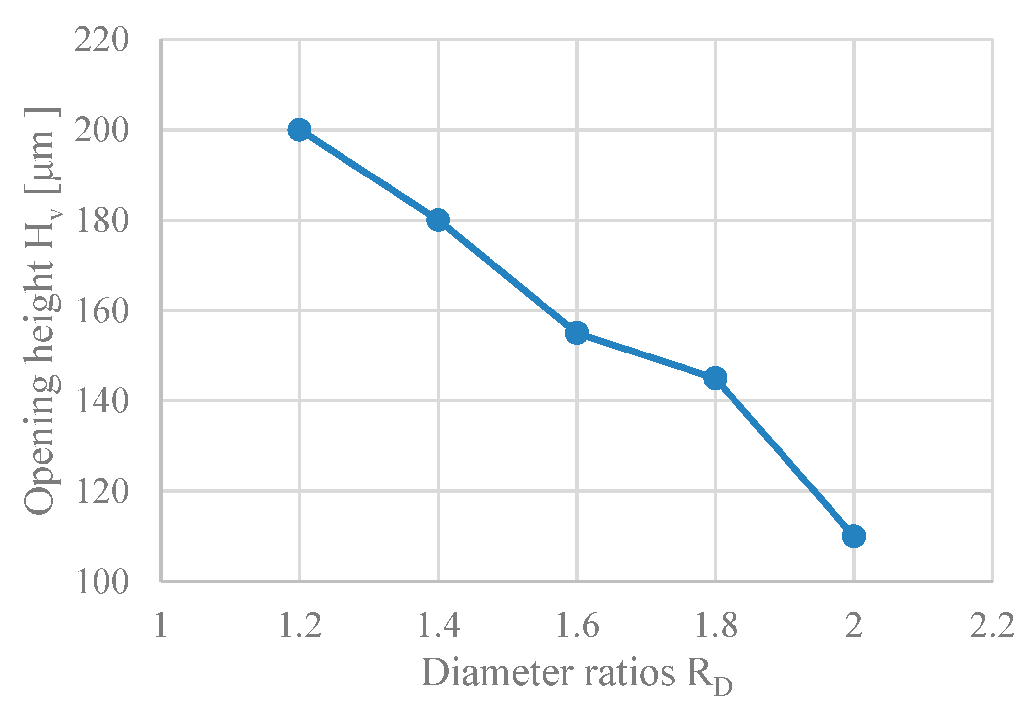
  • When the valve diameter ratios RD are 1.2, 1.4, 1.6, 1.8 and 2.0, measure the valve opening height and air block probability. The experiment results show that when the diameter ratio RD = 1.2, the air block probability is the lowest.
  • When the valve thicknesses are 20, 30, 40, 50 and 60 μm, measure the valve opening height and air block probability. The experiment result shows that when the thickness t = 20 μm, the air block probability is the lowest.
  • Within the samples, the best combination of the valve is when the diameter ratio RD = 1.2 and thickness t = 20 μm. Under this combination, the valve opening height Hv is 252 μm, and within the given bubble volumes, the air block probability is below 2%.

Acknowledgments

This study is supported by the National Natural Science Foundation of China (Grant No. 51406065).

Author Contributions

Yong Liu: responsible for the overall planning and task assignment, main composition and modification work in the paper. Song Chen: responsible for experiment, original data collection, composition of the paper draft. Yanhu Shen: responsible for deduction of the formula. Jiantao Wang: responsible for figures and tables creation and prototype assembly. Zhigang Yang: instruct on the paper theory and experiment method.

Conflicts of Interest

The authors declare no conflict of interest.

References

  1. Wu, Y. Dynamic Analysis and Optimal Design of Piezoelectric Pump; Jilin University: Jilin, China, 2013. [Google Scholar]
  2. Abhari, F.; Jaafar, H.; Yunus, N.A.M. A comprehensive study of micropumps technologies. Int. J. Electrochem. Sci. 2012, 7, 9765–9780. [Google Scholar]
  3. Jiang, D.; Li, S.-J.; Yang, P. Experimental study on the influence of bubbles on dynamic characteristics of valve-less micropump. J. Exp. Fluid Mech. 2010, 24, 34–38. (In Chinese) [Google Scholar]
  4. Woias, P. Micropumps—Past, progress and future prospects. Sens. Actuators B Chem. 2005, 105, 28–38. [Google Scholar] [CrossRef]
  5. Andersson, H.; van der Wijngaart, W.; Nilsson, P.; Enoksson, P.; Stemme, G. A valve-less diffuser micropump for microfluidic analytical systems. Sens. Actuators B 2001, 72, 259–265. [Google Scholar] [CrossRef]
  6. Linnemann, R.; Woias, P.; Senfft, C.-D.; Ditterich, J.A. A self-priming and bubble-tolerant piezoelectric silicon micro pump for liquids and gases. In Proceedings of the Micro Electro Mechanical Systems, Heidelberg, Germany, 25–29 January 1998; pp. 532–537.
  7. Ikuta, K.; Hasegawa, T.; Adachi, T. SMA micro pump chip to flow liquid and gases. In Proceedings of the International Conference on Shape Memory and Superelastic Technologies, Tsukuba City, Japan, 3–5 December 2007; pp. 343–350.
  8. Inman, W.; Domansky, K.; Serdy, J.; Owens, B.; Trumper, D.; Griffith, L.G. Design, modeling and fabrication of a constant flow pneumatic micropump. J. Micromech. Microeng. 2007, 17, 891–899. [Google Scholar] [CrossRef]
  9. Richter, M.; Congar, Y.; Nissen, J.; Neumayer, G.; Heinrich, K.; Wackerle, M. Development of a multi-material micropump. J. Mech. Eng. Sci. 2006, 220, 1619–1624. [Google Scholar] [CrossRef]
  10. Richter, M.; Linnemann, R.; Woias, P. Robust design of gas and liquid micropumps. Sens. Actuators A Phys. 1998, 68, 480–486. [Google Scholar] [CrossRef]
  11. Sun, X.-F.; Li, X.-X.; Yang, Z.-G.; Lin, J.-L.; Cheng, G.-M. Piezoelectric membrane pump with series connected double chambers and holistic opening valve. J. Jilin Univ. Eng. Technol. Ed. 2006, 36, 529–533. (In Chinese) [Google Scholar]
  12. Yamahata, C.; Lacharme, F.; Burri, Y.; Martin Gijs, A.M. A ball valve micropump in glass fabricated by powder blasting. Sens. Actuators B Chem. 2005, 110, 1–7. [Google Scholar] [CrossRef]
  13. Nisar, A.; Afzulpurkar, N.; Mahaisavariya, B.; Tuantranont, A. MEMS-based micropumps in drug delivery and biomedical applications. Sens. Actuators B Chem. 2008, 130, 917–942. [Google Scholar] [CrossRef]
  14. Nguyen, N.T.; Truong, T.Q.; Wong, K.K.; Ho, S.S.; Low, L.N. Micro check valves for integration into polymeric microfluidic devices. J. Micromech. Microeng. 2004, 14, 69–75. [Google Scholar] [CrossRef]
  15. Nguyen, N.T.; Truong, T.Q. A fully polymeric micropump with piezoelectric actuator. Sens. Actuators B Chem. 2004, 97, 137–143. [Google Scholar] [CrossRef]
  16. Truong, T.Q.; Nguyen, N.T. A polymeric piezoelectric micropump based on lamination technology. J. Micromech. Microeng. 2004, 14, 632–638. [Google Scholar] [CrossRef]
  17. Wong, H.; Radke, C.J.; Morris, S. The motion of long bubbles in polygonal Capillaries: Part 2: Drag, fluid pressure and fluid flow. J. Fluid Mech. 1995, 292, 95–110. [Google Scholar] [CrossRef]
  18. Kreutzer, M.T.; Kapteijin, F.; Moulijn, J.A. Inertial and interfacial effects on pressure drop of Taylor flow in capillaries. AIChE J. 2005, 51, 2428–2440. [Google Scholar] [CrossRef]
  19. Choi, C.W.; Yu, D.I.; Kim, M.H. Adiabatic two-phase flow in rectangular micro channels with different aspect ratios: Part II—Bubble behaviors and pressure drop in single bubble. Int. J. Heat Mass Transf. 2010, 53, 5242–5249. [Google Scholar] [CrossRef]
  20. Bretherton, F.P. The motion of long bubbles in tubes. J. Fluid Mech. 1961, 10, 166–168. [Google Scholar] [CrossRef]
  21. John, E.; Joseph, F.; Franzini, B. Fluid Mechanicas with Engineering Applications; Tsinghua University press: Beijing, China, 2003. [Google Scholar]
  22. Liu, Y. Theoretical & Experimental Study on Wheel Valve Micro-Piezoelectric Pump; Jilin University: Jilin, China, 2012. [Google Scholar]
  23. Wen, S.-Z.; Huang, P.; Liu, Y.; Qian, L.-M.; Tian, Y.; Liu, Y.-H. Interface Science and Technology; Tsinghua University press: Beijing, China, 2011. [Google Scholar]

