


Abstract
While piezoelectric vibrating-mesh atomizers are widely utilized for nebulization, their application in inkjet printing and fluid dispensing is hindered by spreading ejection, satellite deposits formation, and restricted working distances. In this study, we found that piezoelectric vibrating-membrane ejectors (PVMEs) featuring a single micro-orifice switch their ejection states between two distinct modes, namely, aligned and spreading, depending on the orifice size and actuation-voltage amplitude. This feature offers a new opportunity for using these vibrating membrane-based devices to perform precise inkjet printing or fluid dispensing at working distances of ≥1 mm. Mechanism analysis attributes the change in ejection mode to air bubble generation via cavitation and/or air intrusion, where partial blockage and/or asymmetric collapse induces off-axis jetting. The water ejection flow rate in the aligned mode was fitted and evaluated with a physical model that suggests the ejected liquid volume is proportional to the volume change in the liquid chamber caused by membrane vibration. Uniform and non-uniform droplet sizes were observed for the aligned and spreading ejection modes, respectively. The 22 and 11 µm orifice PVMEs exhibited aligned ejection of aqueous glycerol solutions with viscosities up to 22.5 mPa · s, indicating their suitability for ejecting water- or solvent-based liquids. The printability of the PVME-based printheads was validated at different working distances through the printing of dots, lines, interdigitated electrodes, and ink dots for die inking. As a result of the different ejection modes, clean dots and lines with feature sizes of several hundred micrometers can be printed with the 22 and 11 µm orifice PVMEs at relatively long working distances (≥1 mm), whereas for smaller feature sizes, i.e., as small as approximately 50 µm, a 6 or 3 µm orifice PVME has to be used at a short working distance (≤1 mm). These findings establish the PVME method as a structurally simple, power-efficient, and cost-effective alternative for precise inkjet-printing and fluid-dispensing applications.
1. Introduction
Controlled fluid deposition represents an important category of technologies used across diverse application sectors. In inkjet printing, printers are used to deposit ink droplets into predefined patterns [1,2]. In electronic packaging and the broader manufacturing industry, fluid-dispensing systems are widely employed to apply controlled amounts of liquids, pastes, or gels [3,4]. In the pharmaceutical and life sciences fields, automated liquid-dispensing systems are used to enable more efficient and precise sample preparation [5,6]. The inkjet printers, fluid-dispensing systems, and automated liquid-dispensing systems come in various shapes and are designed to work with fluids of varying physicochemical and rheological properties for different purposes [7,8,9,10]. However, their technical commonality lies in the precise controlled release of fluid materials, achieved through printheads or fluid-dispensing valves.
In the realm of inkjet printing, existing printhead technologies include continuous inkjet, thermal/piezoelectric printheads, and electrohydrodynamic, aerosol, and plasma jet printing [1,11,12]. Meanwhile, in the realm of fluid dispensing, dispensing valve technologies are categorized as time-pressure dispensing, rotary screw (auger) valve dispensers, piston, diaphragm, and needle dispensing valves, as well as pneumatic, piezoelectric, and electromagnetic jet dispensing valves [13,14,15,16,17,18,19,20]. The availability of so many controlled fluid deposition technologies directly reflects the diverse demands for deposition precision, yield, fluid properties, and the trade-off between engineering complexity and performance.
On the other hand, a vibrating-mesh atomizer is a type of nebulizer that uses a thin membrane with multiple pinholes to convert a liquid into a fine mist [21,22]. Typically, a thin metal membrane is laser-drilled with hundreds or thousands of conical-shaped micro-holes. The membrane is bonded to a piezoelectric unit which makes it vibrate at the resonant frequency. During vibration, the liquid is driven into the micro-holes and breaks up into micron-sized droplets at the orifices. The structure of vibrating-mesh atomizers is relatively simple, their manufacturing methods are well established, and the atomization process is power-efficient [23,24]. As a result, vibrating-mesh atomizers are widely used in household humidifiers and nebulizers for drug delivery, and have also been tested for spray cooling [25,26,27].
To develop the inkjet-printing capability under this technology, the metal membrane was made with a single micro-hole at its center, resembling the nozzle of a printhead [22]. However, the ejected liquid droplets tended to be separated from each other, making it difficult to avoid unintended satellite deposits when printing solid lines or dots [28]. This behavior originates from the random ejection direction of the droplets, which also causes them to spread during flight [29]. While this is compatible with atomizer applications, it is undesirable for use in precise inkjet printing or liquid dispensing. In this regard, the piezoelectric unit was repositioned on the membrane side opposite to the ejection direction, allowing the orifice to be placed as close to the deposition surface as possible. This approach minimizes the spreading effect after the droplets leave the orifice, so a printed line width down to about 100 μm was reported [30]. Nevertheless, the extremely short working distance also makes deposition onto uneven and 3D surfaces impossible [11,30]. On the other hand, a vibrating-nozzle ejector driven by membrane resonance was reported to generate microdroplets without exhibiting the spreading effect [31]. However, the mechanisms for determining whether the ejection mode is spreading or non-spreading (aligned) remain unclear, and controlled switching between the two modes has not been reported.
In this work, it was found that when adjusting the orifice size and actuation-voltage amplitude, the ejection behavior of the vibrating-membrane-based ejectors actually changes between two distinct modes: aligned and spreading. This enables the possibility of achieving precise inkjet printing or liquid dispensing at relatively long working distances using these ejectors, hereafter referred to as piezoelectric vibrating-membrane ejectors (PVMEs). Air bubble generation was found to be directly related to the change in ejection state from aligned to spreading. By analyzing their dependence on orifice size and actuation-voltage amplitude, a mechanism that explains this change is proposed, which involves the generation of air bubbles by cavitation effect and/or air intrusion from the orifice side, and their partial blockage and/or asymmetric collapse can lead to off-axis jets. Ejection characteristics, including water ejection flow rate, droplet size, and applicable liquid viscosities, were investigated. The relationship between water flow rate and actuation-voltage amplitude was fitted and evaluated using the equation of a physical model, in which the ejected liquid volume is proportional to the volume change in the liquid chamber caused by membrane vibration. Consistent and non-uniform droplet sizes were observed for the aligned and spreading ejection modes, respectively. PVMEs with 22 and 11 µm orifices exhibited aligned ejection of a 22.5 mPa · s aqueous glycerol solution, demonstrating an ejectable-liquid viscosity comparable to that of conventional piezoelectric inkjet printheads. The printability of the PVMEs was further demonstrated by the printing of dots, lines, interdigitated electrodes (IDEs), and ink dots for die inking. Different viable printing scenarios were identified for the 22 and 11 µm orifice PVMEs, which eject in the aligned mode, and for the 6 and 3 µm orifice PVMEs, which eject in the spreading mode.
2. Methods
2.1. Structure of PVMEs
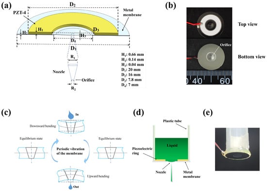
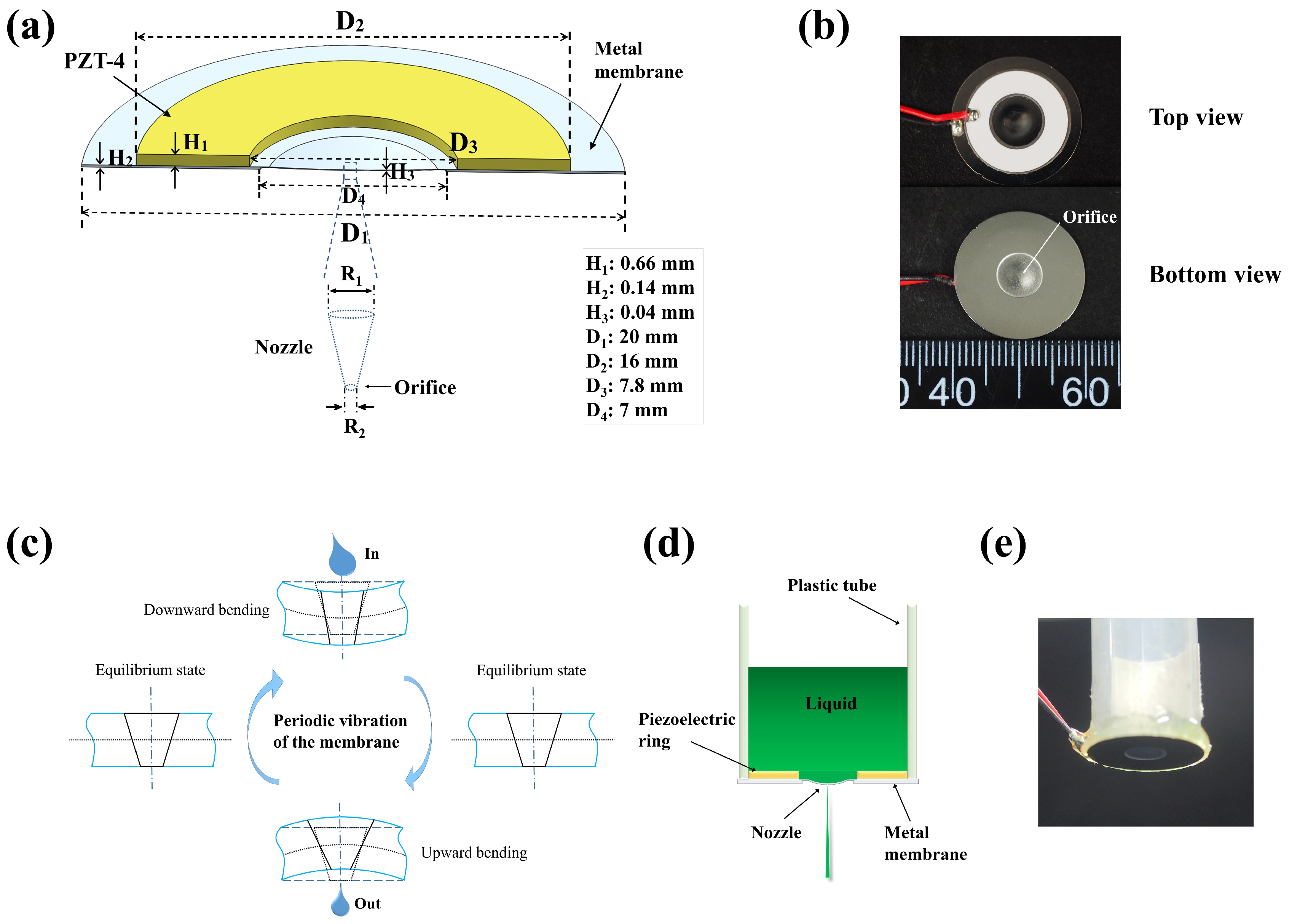
The 3D cross-sectional structure of the custom-made PVMEs is illustrated in Figure 1a. A piezoelectric ring (lead zirconate titanate, PZT-4) is bonded to a circular metal membrane (304 stainless steel) using conductive epoxy adhesive. The piezoelectric ring has a thickness of 0.66 mm and inner and outer diameters of 7.8 mm and 16 mm, respectively. A conical-shaped hole is laser-drilled at the center of the metal membrane, serving as the nozzle. The side with the smaller diameter acts as the orifice for liquid ejection. PVMEs with different nominal orifice diameters (3, 6, 11, and 22 µm) were fabricated. The piezoelectric ring is positioned on top of the membrane so that the nozzle can approach the deposition surface closely. The metal membrane has a thickness of 0.14 mm at its outer part. In the central part, it was laser-thinned to 0.04 mm to enable more effective vibration and also stamped into a convex shape [32]. Electrical connections were soldered to the metal membrane and contact point on the piezoelectric ring. Figure 1b shows the top- and bottom-view images of a PVME. Electron microscopy images of the laser-drilled nozzles were acquired with a scanning electron microscope (SEM) (Phenom Pharos G2, Thermo Fisher, Waltham, MA, USA). The frequency-dependent impedance of the PVMEs was measured using an impedance analyzer (IM3570, Hioki, Nagano, Japan) at the applied test voltage of 1 V peak-to-peak.
Figure 1.
(a) Schematic showing the 3D structure of the piezoelectric vibrating-membrane ejectors. (b) Top and bottom view images of a PVME. (c) Schematic illustration of the jetting principle, showing the different bending states of the membrane during the nozzle jetting and refilling cycles. (d) Schematic illustration of the PVME-based printhead. (e) Actual image of the assembled printhead.
2.2. Jetting Principle of PVMEs
The jetting principle of PVMEs is illustrated in Figure 1c. When an AC voltage at the resonant frequency is applied to the piezoelectric unit, it actuates vibration of the system. During each vibration cycle, the membrane undergoes periodic upward and downward bending at the nozzle area. As the membrane begins to bend upward from its lowest position, it compresses the liquid inside the nozzle, leading to squeezing and ejecting liquid droplets when the pressure in the conical-shaped hole becomes sufficiently high to overcome the surface tension of the liquid. During the reverse cycle, when the membrane begins to bend downward from its highest position, the pressure inside the nozzle drops. The liquid refills the nozzle due to the combined effects of surface tension, capillary force, inertia, and in this case, also gravity [21,33,34]. The jetting action continues as long as the applied AC voltage drives the membrane to oscillate. The size of the ejected droplets is mainly determined by the orifice size at the nozzle outlet [24,35].
2.3. Jetting Characterization and Printing
As illustrated in Figure 1d, the PVME was bonded to a syringe tube to form the printhead and serve as the liquid reservoir. Figure 1e shows an image of the assembled printhead. The sine waveform AC signal was provided by a signal generator (PSG9070, Juntek, Hangzhou, China), and the actuation voltage was amplified by a power amplifier (Feelelec FPA501, FEELTECH, Zhengzhou, China). Pictures of jetting PVMEs were taken with a digital camera (E-M10 II, Olympus, Tokyo, Japan). Deionized water and aqueous solutions of glycerol (≥99.5%, Macklin, Shanghai, China) were tested for ejection characteristics. The flow rate of water ejection was determined by measuring the mass loss over a period of ejection. Briefly, 500 μL of deionized water was added to the printhead reservoir, and the initial printhead mass () was measured using an analytical balance (FA1004, Sunny Hengping Instrument, Shanghai, China). Jetting was performed for 30 s at each voltage except for the 3 μm orifice, for which the duration was 60 s. The final printhead mass () was then recorded. The volumetric flow rate was calculated as , where is the density of water and is the jetting duration. The reservoir was cleaned and refilled before each test, and each condition was tested at least three times. To observe the ejected droplets, a horizontal microscope system was set up close to the PVME. As shown in Figure S1, the LED light source (MJSDT001QW, Xiaomi, Beijing, China) has a luminous flux of 1000 lm, and the camera (MV-CS050-10GC, Hikrobot, Hangzhou, China) supports a minimum exposure time of 1 μs at the resolution of 2448 × 2048 pixels. A microscope calibration ruler was used as a length reference for droplet diameter measurements. Its image was captured at the same magnification and focal distance used for imaging the droplets.
Printing with the PVME-based printhead was performed by mounting it to a three-axis dispensing robot (SM200SX, Musashi, Tokyo, Japan). The distance between the PVME nozzle and the printing surface can be measured with the equipped laser altimeter. Si/SiO2 substrates were sequentially cleaned by ultrasonication in ethanol and deionized water, then dried with N2. Dots and lines were printed on Si/SiO2 substrates using a 5 wt.% aqueous polyvinylpyrrolidone (PVP) (average Mw = 10,000, Macklin) solution or a conductive silver (Ag) ink (viscosity: 2–5 mPa · s, Hunan Xingwei New Materials, Changsha, China). The printed dot diameter and line width were observed and measured using a digital microscope. Interdigitated electrodes of Ag were also printed. The printed Ag structures were heat-treated at 150 °C for 15 min. Demonstration of die inking was performed by printing a die-marking ink (6993, Xandex, Petaluma, CA, USA) onto Si/SiO2 substrates. The ink was diluted with ethanol at an ink-to-ethanol volume ratio of 3:1.
3. Results and Discussion
3.1. Orifice Size and Resonant Frequency
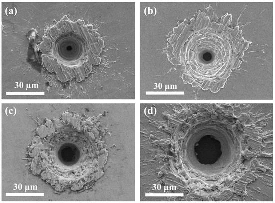
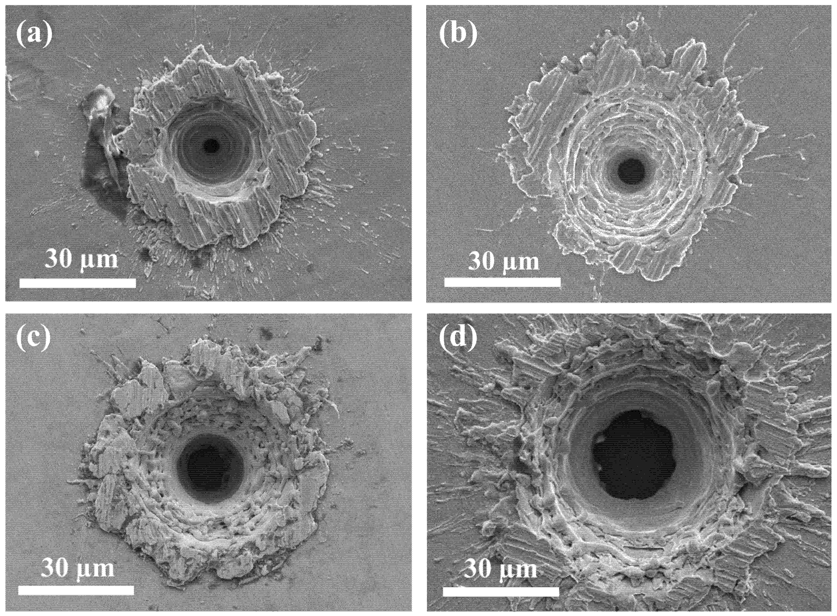
To serve as the nozzle, a single conical-shaped hole of varying size was laser-drilled at the membrane center of each PVME. Figure 2a–d are the SEM images of these conical-shaped holes. It can be seen that melt expulsion and resolidification during the laser-drilling process cause rough sidewalls, yet the overall shape is conical [36]. The orifice diameters at the nozzle outlets were measured to be 3.2 ± 0.1, 6.2 ± 0.5, 11.2 ± 1.1, and 21.8 ± 0.6 µm. These average and standard deviation values were calculated from measurements of at least three devices in each case. Because the orifices were not perfectly circular, the diameter measured along the maximum-diameter direction of each orifice was used as a consistent measurement criterion for calculation. For brevity, these nozzles will hereafter be referred to as the 3, 6, 11, and 22 µm orifices.
Figure 2.
Top-view SEM images of the conical-shaped holes with different orifice sizes: (a) 3.2 ± 0.1 µm in diameter; (b) 6.2 ± 0.5 µm in diameter; (c) 11.2 ± 1.1 µm in diameter; (d) 21.8 ± 0.6 µm in diameter.
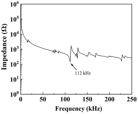
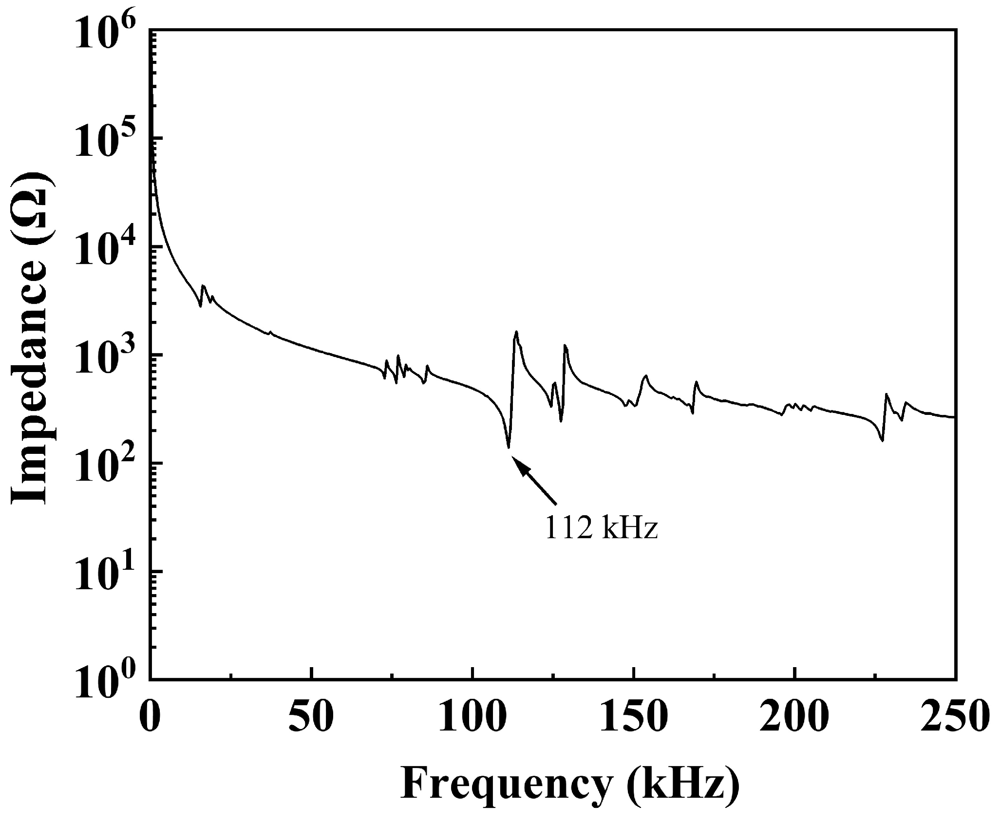
Vibrating-membrane ejectors and atomizers are made to operate at their resonant frequency. Figure 3 shows the frequency-dependent impedance of the PVME. The lowest impedance point occurs at approximately 112 kHz, which also represents the operating frequency at resonance. At this point, the mechanical response is maximized because the electrical excitation is in sync with the natural frequency to vibrate [28]. At other frequencies, liquid atomization or droplet ejection was found to be still possible, but significantly less effective, as higher actuation voltages are required.
Figure 3.
Frequency-dependent impedance of the PVME.
3.2. Ejection States and Mechanism
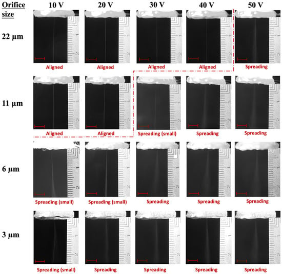
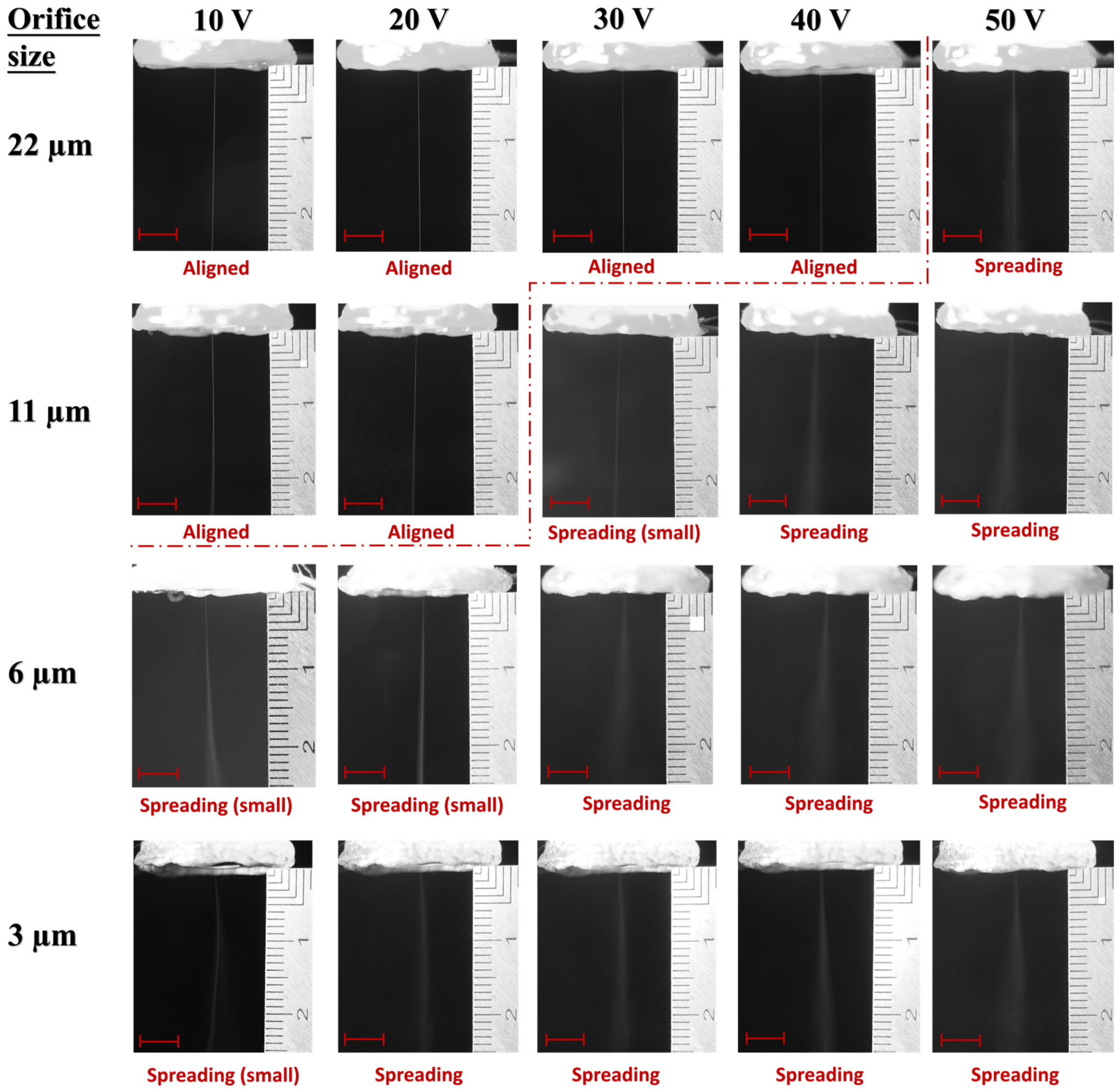
Water ejection was performed at the resonant frequency while increasing actuation-voltage amplitude. As shown in Figure 4, two types of ejection modes were observed: one is aligned ejection of droplets in a line, and the other is spreading ejection of atomization. In between, some mild spreading states were also observed, which appear to be in transition from the aligned to the spreading state. They are regarded as spreading (small) as well. The aligned ejection mode occurred with larger orifice sizes and at lower actuation voltages. Specifically, it was observed with the 22 µm orifice at 10, 20, 30, and 40 V, and with the 11 µm orifice at 10 and 20 V. The 6 and 3 µm orifices did not produce aligned ejection at all. When actuated at 10 V, they exhibited relatively weak ejection compared with larger orifices or higher voltages, making the ejected liquid mist more susceptible to deflection by the surrounding airflow. As can be seen, the mists ejected from the 6 and 3 μm orifices at 10 V were already deflected from the initial central axis by the surrounding airflow at distances of approximately 10 and 5 mm downstream of the nozzle, respectively. In contrast, for larger orifices or higher actuation voltages, the initial ejection trajectory can be maintained over longer distances, despite the presence of a certain spreading effect. In all cases of orifice sizes, further increasing the actuation voltage only enhanced the spreading effect further (see Figure S2 for voltages up to 80 V). In the aligned ejection mode, the droplet line could remain straight over distances of about 20 mm with the 22 µm orifice and about 10 mm with the 11 µm orifice. This indicates that the smaller flow resistance of the 22 µm orifice allows the ejected droplets to travel farther before getting scattered. Although the dual operation modes shown above suggest that the ejector is applicable to both inkjet printing and spray coating, this work focuses on the inkjet printing of fine patterns.
Figure 4.
Water ejection images of PVMEs with different orifice sizes at voltage amplitudes ranging from 10 to 50 V (peak-to-peak). The dashed lines mark the boundaries between the aligned and spreading modes. The scale bars in each image represent a length of 5 mm, and the images are not compressed in any direction (the numbered divisions on the ruler are in their actual font).
Also noticed was the generation of air bubbles from the nozzle. As shown in Figure S3, the generation of air bubbles is also orifice size- and actuation voltage-related, and a strong correlation between air bubble generation and the switching of the ejection mode from aligned to spreading ejection was observed. No continuous generation of air bubbles can be seen when the nozzles were ejecting in the aligned mode. In contrast, when an increase in voltage caused the ejector to switch from aligned to spreading ejection, continuous generation of air bubbles occurred. The air bubbles started small and sparse, then became larger and more numerous as the voltage increased. This also matches with the gradual enhancement of the spreading effect observed in the spreading ejection mode.
The generation of air bubbles was reported by Maehara et al. in an early study of vibrating-mesh atomizers [21]. Cavitation was suggested as the cause of bubbles, which generally consist of two components: vapor bubbles, created when local pressure drops below the liquid’s vapor pressure, and dissolved air that diffuses into these cavities. On the other hand, the possibility of air being drawn into the nozzle at the orifice side during vibration cannot be excluded, as the pumping effect in the reverse direction is evidenced by the reverse direction atomization of vibrating-mesh atomizers [37].
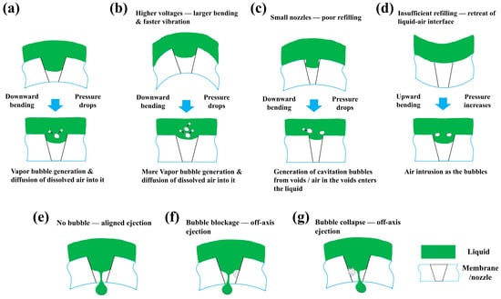
With a membrane and nozzle vibrating up and down, the pressure drops dramatically when they vibrate downward, the vapor bubbles therefore can be created. Previous simulations using finite element modeling have shown that the vibration speed and amplitude of the membrane increase with driving voltage [30,38]. The increasing number and size of bubbles with rising voltage is a sign that vapor bubble generation is stimulated by the faster and larger vibrations at higher voltages. Also, a larger vibration amplitude may cause a deeper retreat of the liquid–air interface during the downward bending phase, thereby enhancing the chance of air intrusion when the membrane rebounds [39]. For smaller nozzles, it is harder for the liquid to refill the nozzle during each replenishment phase. As a result, voids are more likely to form in or near the nozzle. These voids promote more extreme low-pressure conditions that induce cavitation, and simultaneously supply air that can enter the liquid. Therefore, cavitation bubbles and air intrusion are more likely to occur in smaller nozzles, even at low driving voltages, which is 10 V for the 3 and 6 µm orifices. Figure 5a–d illustrate the possible air bubble generation mechanisms described above [40,41,42].
Figure 5.
Schematic illustration of bubble generation mechanisms and droplet ejection processes in the aligned and spreading modes. (a) Cavitation bubble generation due to liquid vaporization and dissolved air diffusion. (b) More vapor generation under higher actuation voltages. (c) Cavitation bubble generation from voids due to poor refilling of small nozzles, air in the voids may enter the liquid as well. (d) Air intrusion as the liquid–air interface retreats during vibration and the membrane rebounds afterward. (e) Aligned droplet ejection when the membrane bends upward. (f) Off-axis ejection due to bubble blockage. (g) Off-axis ejection due to bubble collapse.
As illustrated in Figure 5e–g, when the membrane switches from bending downward to upward, the nozzle enters the ejection phase. During this phase, the local pressure rises and drives the liquid to eject droplets along the nozzle axis. If a bubble sits at the side wall of an orifice and partially blocks it, the meniscus becomes tilted, so the emerging jet is directed at an angle rather than along the nozzle axis. In addition, the high pressure also compresses the bubbles and cause them to collapse. A lateral momentum from asymmetric collapse could deflect the flow and produce off-axis ejection.
Based on above discussions, the mechanism of switching from aligned to spreading ejection is summarized as follows: the pressure drop during the downward bending generates cavitation bubbles, which are facilitated by higher voltage and a smaller nozzle; air may also be drawn in from the orifice side as the liquid–air interface retreats during vibration and the membrane subsequently rebounds, supplemented by air from the voids due to incomplete refilling; and the partial blockage and/or asymmetric collapse of bubbles lead to off-axis jets. Together, these effects result in seemingly random jetting directions in the spreading ejection mode.
3.3. Ejection Characteristics
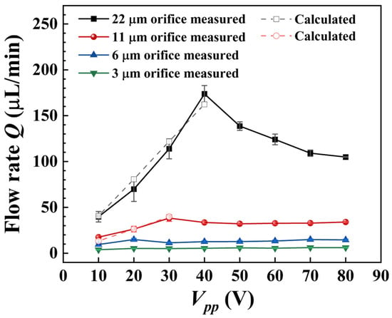
Flow rate measurements of water were conducted for PVMEs with different nozzle sizes at varying voltages. As shown in Figure 6, a general trend of higher flow rates with larger nozzle orifices can be seen, reflecting the dependence of ejected droplet size on orifice size. When increasing the driving voltage, the flow rate typically increases for vibrating-mesh atomizers, as both the vibration speed and membrane displacement rise with voltage [24]. However, for the single-nozzle PVMEs with 11 and 22 µm orifices, the flow rate starts to decline at certain voltages after the initial rise, with the peak flow rate occurring around the switching voltages from aligned to spreading ejection. This is consistent with the above findings, which suggest that bubbles are the cause of the change to spreading ejection, as the bubbles may reduce the flow rate due to their blocking effect; high compressibility, which releases the pressure; and the disruption of meniscus and jet formation [39]. In this sense, the voltage of the highest flow rate would be the point right before bubbles cause the ejection state to change from aligned to spreading. However, since the tests were done with an interval of every 10 V, no exact match of ejection state switching and maximum flow rate voltages was recorded, as those points could be in between the intervals. Nevertheless, the flow rate results already support the proposed mechanism, which involves air bubbles disturbing the ejection, leading to spreading ejection, and lowering the flow rate. Furthermore, the 3 and 6 µm orifice PVMEs only ejected in the spreading mode, meaning that bubble generation was always involved, so no obvious flow rate peak was observed. Instead, they tend to maintain relatively stable flow rates, which can be attributed to the counteraction between the increasing voltage and bubble generation. The same explanation applies to the 11 and 22 µm orifice PVMEs when they tend to reach a quasi-steady flow rate after the peak.
Figure 6.
Ejection flow rate of water vs. actuation-voltage amplitude of PVMEs with different orifice sizes. The error bars represent the standard deviations derived from repeated measurements using the same PVME. The flow rate in the rising regions was fitted using Equation (2), and the corresponding values were calculated with the fitted .
According to Cai et al., the flow rate of vibrating-membrane atomizers can be calculated using the following equation [33,43]:
where is the change in the liquid chamber volume caused by the membrane vibration, is the volume change in the nozzle aperture, is the vibration frequency, is the number of nozzles, and represents the effective pressure loss coefficient. Since the volume change in the nozzle aperture has been reported to be very small and negligible, and only one nozzle is presented in the PVMEs, Equation (1) simplifies to [44,45]:
Using membrane displacement data from the vibration simulations reported in our previous work, at different driving voltages was calculated via the shell method of integration [30,44]. The detailed calculation process is provided in the Supporting Information. Considering that the single nozzle is located at the center of the membrane, only the central part of the membrane deformation was integrated to calculate the volume change. The initial equilibrium position of the membrane was used as the threshold, meaning that the calculated volume change corresponds to the difference between the equilibrium position and the maximum displacement.
As shown in Figure S4b, the calculated versus measured data in the rising regions were fitted with Equation (2). The effective pressure loss coefficients of = 2.93 × 10⁻³ and 0.95 × 10⁻³ were obtained for the 22 and 11 µm orifices, respectively. The flow rate at different voltages can then be calculated using and . The dashed lines in Figure 6 show a good match between the calculated and measured for 22 and 11 µm orifices, indicating that PVMEs follow Equation (1) and its physical model during the aligned and transition states, which suggests that the ejected volume is proportional to the volume change, and this is valid before the bubbles completely disturb the ejection and cause spreading.
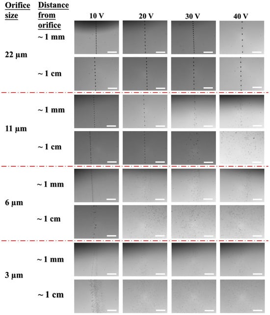
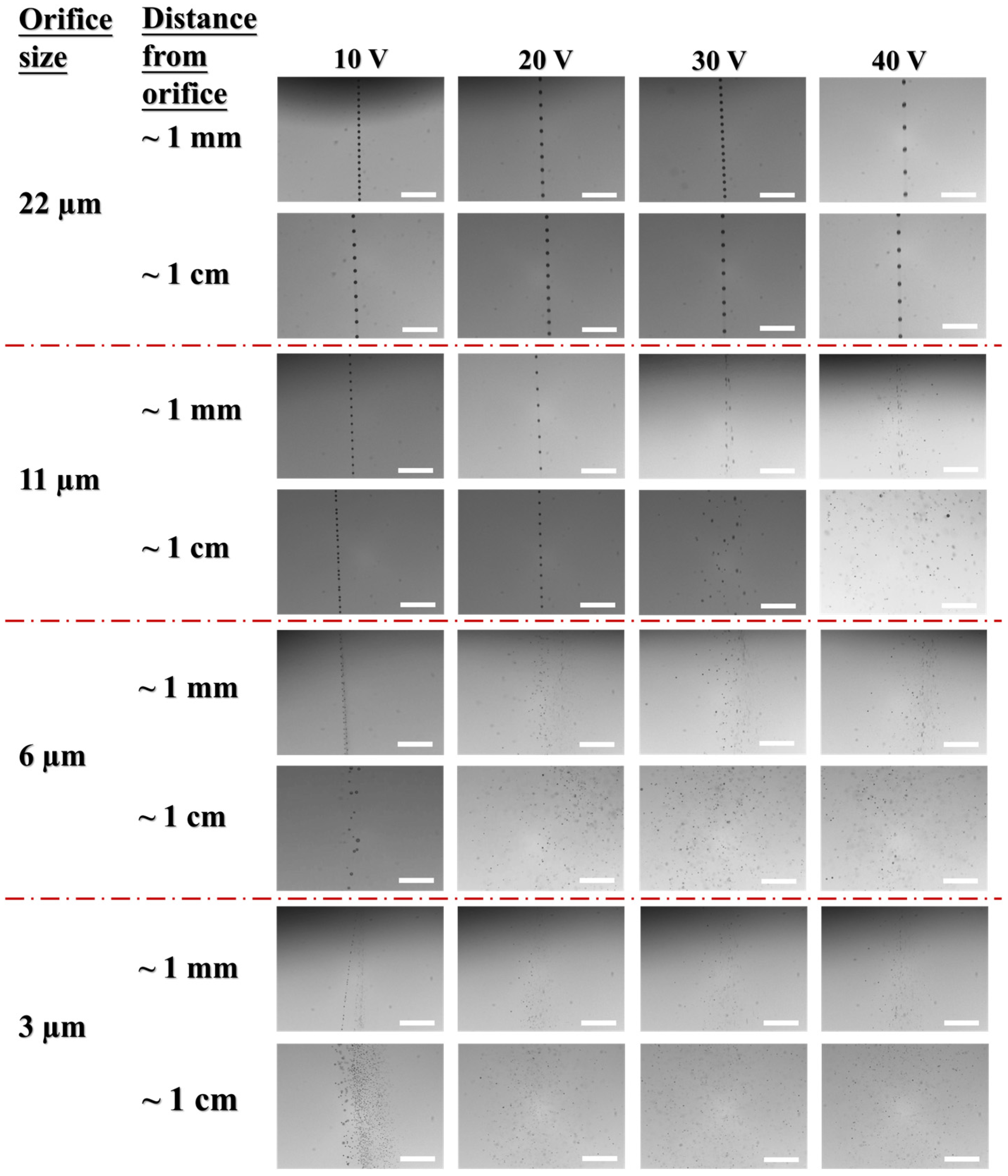
Figure 7 shows images of droplets ejected by the PVMEs at different voltages, captured at distances of approximately 1 mm and 1 cm from the orifice. Under conditions corresponding to the aligned ejection mode, a single droplet line is observed both near the nozzle exit and at a distance of about 1 cm from the orifice. The droplet size in the single droplet line exhibits dependence on both the orifice size and actuation voltage. The droplet diameters were estimated to be 22.6, 27.0, 33.6, and 35.8 µm for the 22 µm orifice at 10, 20, 30, and 40 V, respectively, and 16.8 and 20.4 µm for the 11 µm orifice at 10 and 20 V, respectively. With the estimated droplet diameter and an ejection frequency of 112 kHz, flow rates were calculated and compared with those measured by weight change. Figure S5 shows a reasonable agreement between the two methods, with the largest deviation being about 17% from that measured by weight change. The discrepancy could arise either during the weight measurement or from image blur of the droplet caused by misfocus or an exposure time that is not short enough. A clear transition from aligned to spreading ejection is shown for the 11 µm orifice when the voltage is increased from 20 V to 30 V. In the conditions that belong to the spreading ejection mode, the spreading effect becomes more pronounced as the voltage increases. At a distance of about 1 cm from the orifice, the entire spray actually could not be captured in the image when the voltage exceeded 10 V. In the spreading mode, the ejected droplets also showed diverse sizes at a specific given voltage. This explains why a broad droplet size distribution around the orifice diameter is always present in vibrating-mesh atomizers [46,47].
Figure 7.
Ejected water droplets by PVMEs at different voltages ranging from 10 to 40 V (peak-to-peak). The scale bars in each image represent a length of 500 µm.
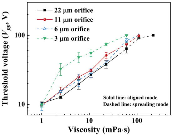
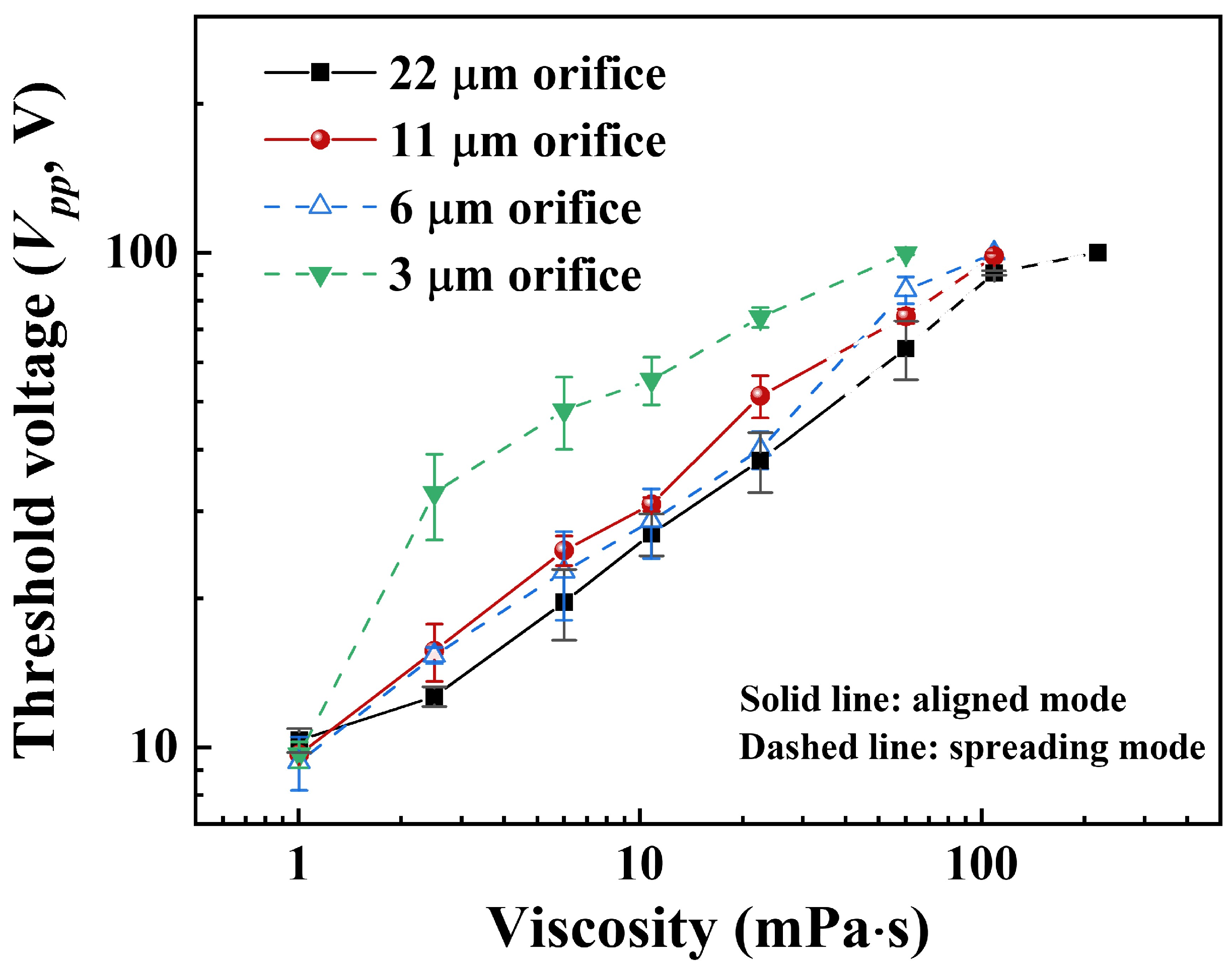
Printable liquid properties, especially viscosity, are important considerations for the application of inkjet printheads. To examine the applicable viscosity range of the PVMEs, glycerol solutions of different weight percentages in water were tested for ejection. The corresponding viscosity values were obtained according to Ref. [48]. Figure 8 shows the threshold voltages at which the ejection was enabled upon increasing the voltage for each viscosity tested. The corresponding jetting images are shown in Figure S6. It can be seen that the threshold voltage increases with viscosity. The 3 and 6 µm orifices ejected only in the spreading mode, which is consistent with the water tests. With the 11 and 22 µm orifices, ejection remained in the aligned mode up to a viscosity of 22.5 mPa · s, and then changed to the spreading mode. This is also reasonable as the required threshold voltages then exceeded 50 V. As the flow resistance increases with decreasing nozzle size, it is expectable that the threshold voltage is overall highest for the 3 µm orifice and lowest for the 22 µm orifice. For the 6 and 11 µm orifices, the lower threshold voltage for the 6 µm orifice is ascribed to their different ejection modes. The 6 µm orifice ejects only in the spreading mode, generating droplets with a wide size distribution, among which a large fraction are smaller than the orifice size. As a result, the flow resistance from the nozzle and ejection threshold voltages would be lower. Once the 11 µm orifice had changed its ejection mode from aligned to spreading at viscosities above 22.5 mPa · s, all nozzles were ejecting in the spreading mode, and the expected order of higher threshold voltage for smaller orifices was restored.
Figure 8.
Ejection threshold voltages of PVMEs tested using aqueous glycerol solutions of different weight percentages, which were then converted into corresponding viscosity values. Error bars represent the standard deviation derived from tests performed on three different PVMEs of each size.
Regarding the applicable viscosity range, 22 and 11 µm orifices demonstrated ejection of 22.5 mPa · s aqueous glycerol solution in the aligned mode. This level of viscosity is substantially lower than that of piezoelectric jet dispensing valves, which employ piezoelectric stacks and amplifying mechanisms to enhance actuation displacement, but is comparable to that of piezoelectric inkjet printheads [11,49,50]. Therefore, the PVMEs with 22 and 11 µm orifices are suitable for printing water- or solvent-based inks for printed electronics or labeling applications using the aligned mode. In the case of the spreading mode, the displayed 60 mPa · s for the 3 µm orifice, 109 mPa · s for the 6 and 11 µm orifices, and 219 mPa · s for the 22 µm orifice are limited by the maximum output voltage of the power supply, meaning that even higher viscosities are still possible.
3.4. Printing Demonstrations
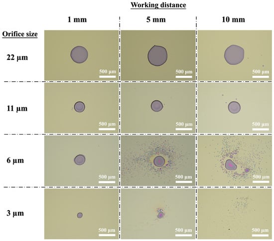
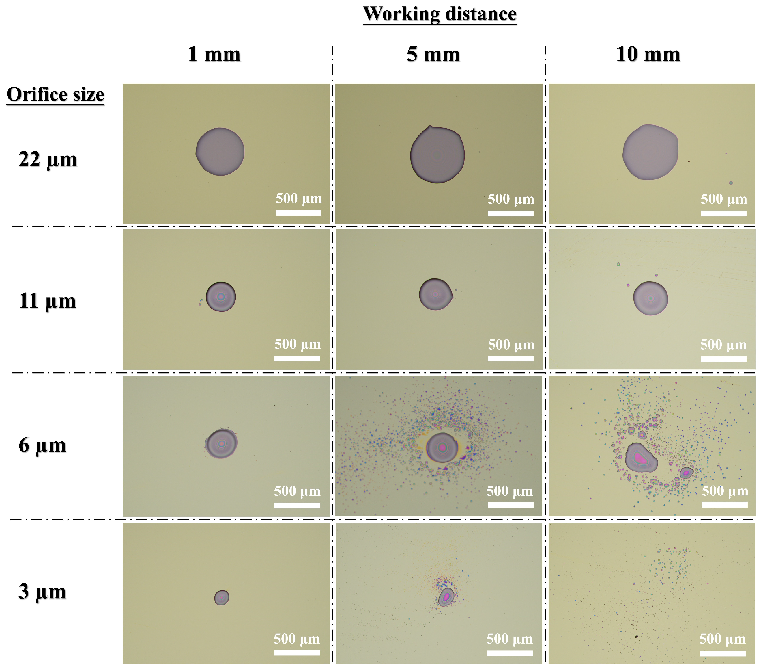
Printing capability of the PVMEs was then assessed by printing dots and lines using the aqueous PVP solution or Ag conductive ink. As shown in Figure 9, primary PVP dots with minimal satellite deposits were consistently obtained using the 22 and 11 µm orifices at nozzle-to-substrate distances of 1, 5, and 10 mm. This result reflects the aligned jetting behavior of PVMEs with a 22 or 11 µm orifice, demonstrating the capability to operate at relatively long distances. With the 6 and 3 µm orifices, however, a single primary dot was obtained only at the working distance of 1 mm. Due to the spreading behavior, substantial satellite deposits were presented at longer distances. With the 3 µm orifice at 1 mm, the single main dot exhibited a minimum diameter of approximately 160 µm, which is also attributed to the small size of the droplets ejected by the orifice. In contrast, no emerged central dot was formed at the distance of 10 mm.
Figure 9.
Results of PVP dot printing using PVMEs at different nozzle-to-substrate distances. The ejection time for each dot was 0.01 s, and the ejection threshold voltages were used.
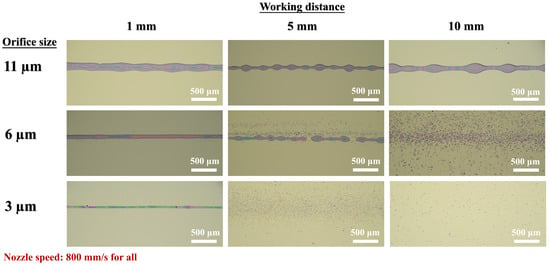
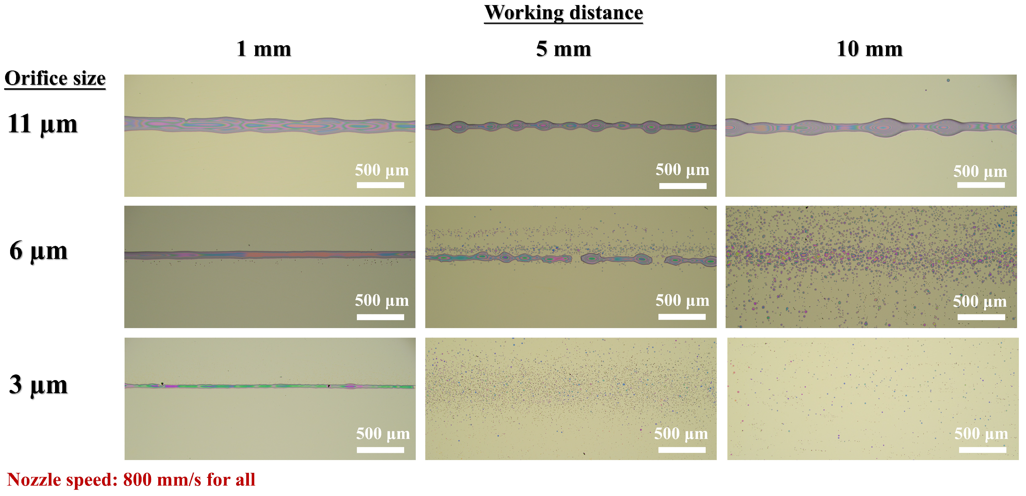
For line printing, the results are similar to those of dot printing. As shown in Figure 10, continuous and clean lines can be printed with the 11 µm orifice at all three tested working distances, or using the 6 and 3 µm orifices at a short distance of 1 mm. The nozzle moving speed was set to 800 mm/s, and the corresponding ejection threshold voltages were applied to obtain relatively narrow line widths. The lines printed with the 6 and 3 µm orifices at 1 mm working distance measured a width of about 84 and 47 µm at their widest sections, respectively. At longer working distances, the printed material by the 6 and 3 µm orifices was either discontinuous or reduced to scattered PVP dots. Figure S7 shows that by printing with the 6 µm orifice at a reduced nozzle speed of 400 mm/s, more solution can be accumulated, so the continuous line shape was restored at working distances of 5 and 10 mm. However, the problem of excessive satellite deposits remained. For the 3 µm orifice, a nozzle speed as low as 100 mm/s was not enough to make the scattered droplets merge into a continuous line.
Figure 10.
Results of PVP line printing using PVMEs at different nozzle-to-substrate distances. The nozzle moving speed was 800 mm/s, and the ejection threshold voltages were used.
The above results indicate that orifice size and working distance are two critical parameters that should be considered when using PVMEs to print fine patterns. For medium-scale features spanning several hundred micrometers, larger orifices (22 and 11 µm) can be utilized at longer working distances. However, printing fine patterns of around 100 µm or below necessitates the use of smaller orifices (6 and 3 µm) paired with a short working distance.
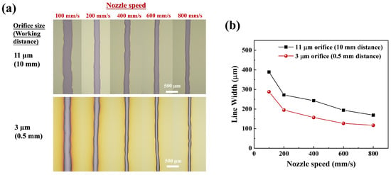
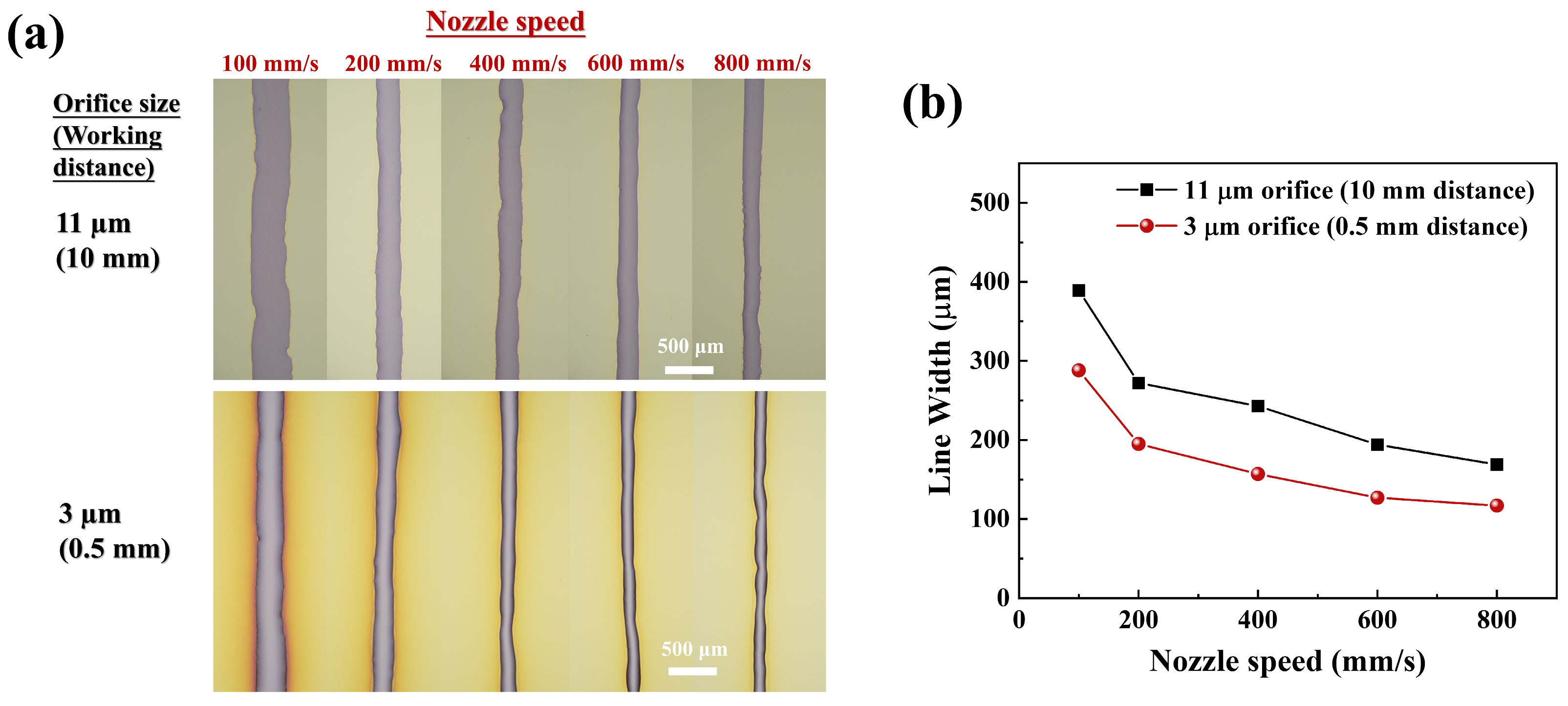
As nozzle moving speed is another printing parameter that affects the print outcome, its impact on line width was further demonstrated by printing Ag conductive lines. As shown in Figure 11a, clean Ag lines were printed with the 11 µm orifice at a working distance of 10 mm and with the 3 µm orifice at a working distance of 0.5 mm, respectively. A decreasing trend in line width with increasing speed can be identified in both printing settings. As shown in Figure 11b, the 3 µm orifice produced consistently narrower lines, measuring approximately 117 µm in width at 800 mm/s. Table S1 summarizes and compares the printing performance metrics of the PVMEs investigated in this work with those of conventional inkjet printing [51].
Figure 11.
Results of Ag line printing using PVMEs at different nozzle moving speeds: (a) microscopic images; (b) measured line widths. The nozzle-to-substrate distances were 10 and 0.5 mm for the 11 and 3 µm orifices, respectively, and the ejection threshold voltages were used.
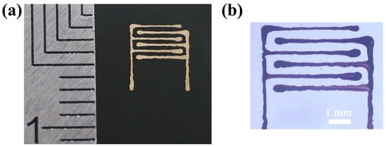
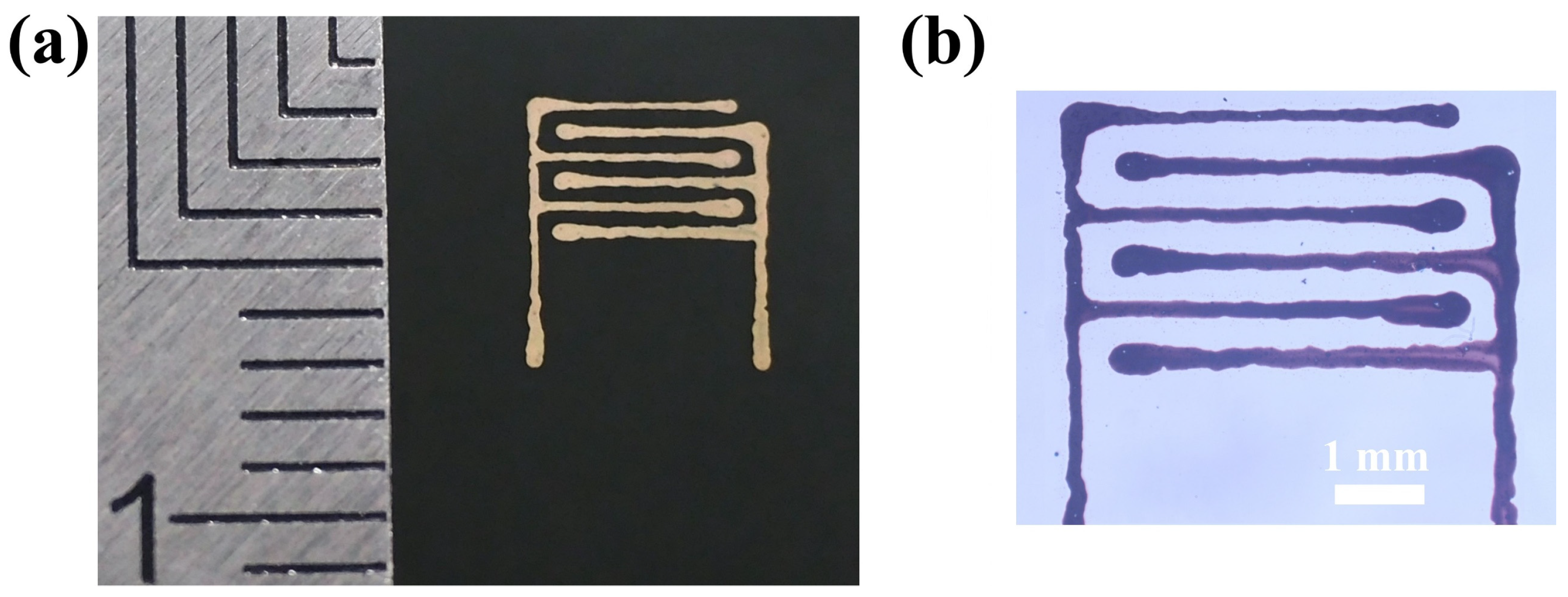
Figure 12 shows images of the interdigitated electrodes printed using the 3 µm orifice. The total area of the IDEs is about 5 mm × 5 mm. To achieve miniaturization, printing was performed at 250 µm working distance, 200 mm/s nozzle speed, and 30 V peak-to-peak voltage. The sample was annealed at 150 °C after printing. Due to fluid dynamics during the printing process, the printed Ag electrodes exhibit some non-uniformity in width; nevertheless, this still demonstrates the viability of using PVMEs for practical printing applications.
Figure 12.
Images of the interdigitated electrodes printed on the Si/SiO2 substrate using a PVME with a 3 µm orifice: (a) camera image; (b) digital microscope image.
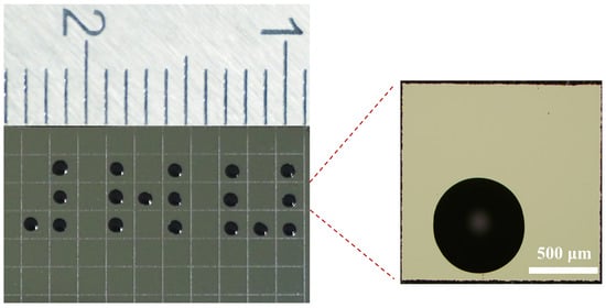
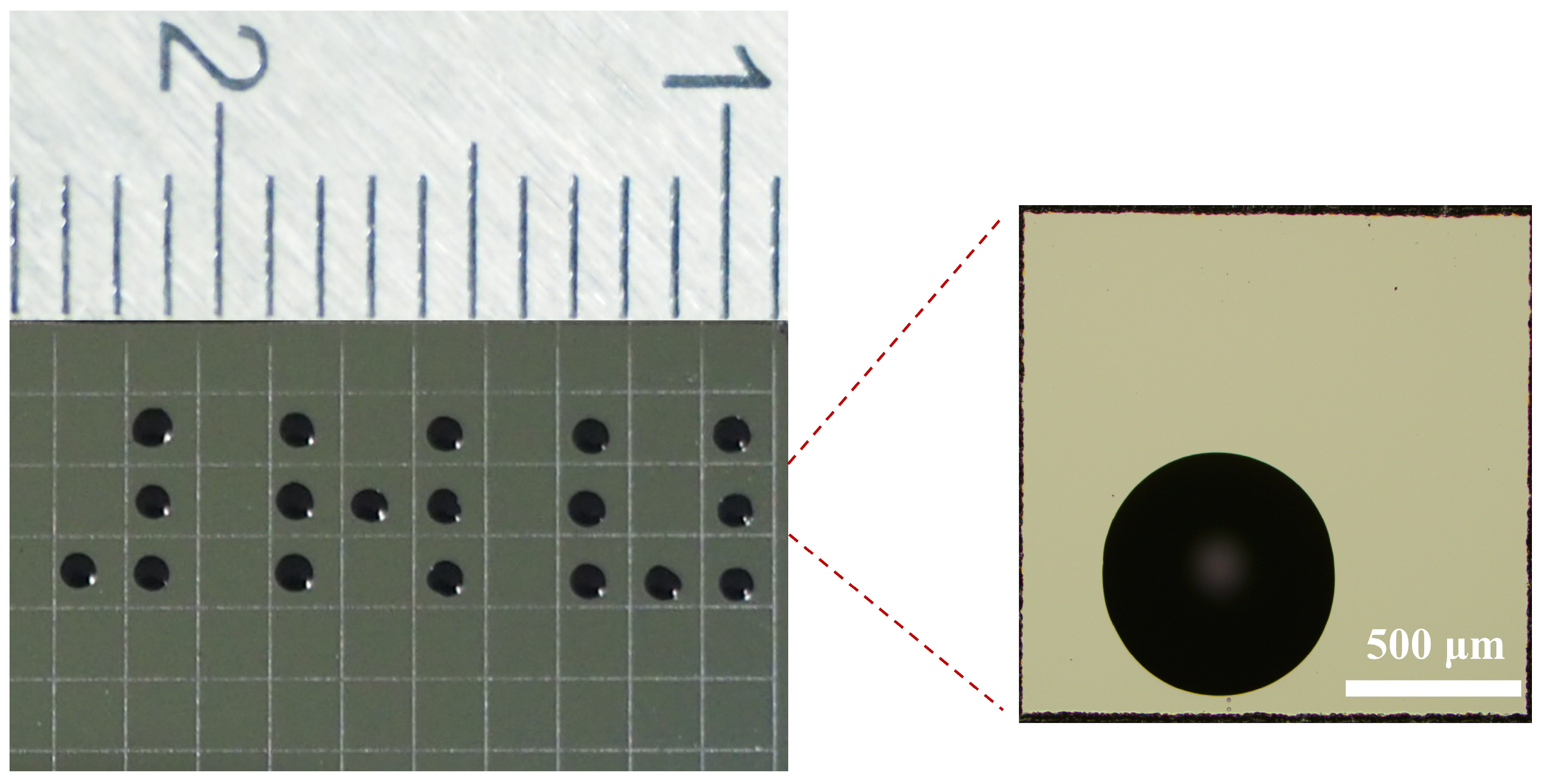
Further demonstration of application was performed with the printing of die-marking ink. Die inking is the conventional method of marking defective dies that are found in a chip probing test. The failed dies will be excluded from further packaging. As shown in Figure 13, the Si/SiO2 substrate was laser-scribed with an orthogonal grid to simulate a wafer and individual dies. To reduce the viscosity and lower the required actuation voltage threshold, the original ink was diluted with ethanol at an ink-to-ethanol volume ratio of 3:1. Ink dots were then printed on selected blocks representing failed dies, and these dots also formed the letters JNU. Printing was performed using a PVME-based printhead with a 22 µm orifice at the working distance of 3 mm. The ejection time was 0.01 s for each dot, and the ejection threshold voltage of 60 V peak-to-peak was applied. The average diameter of the printed ink dots was measured to be 759 ± 25 µm.
Figure 13.
Printing of die-marking ink onto selected blocks on a Si/SiO2 substrate, simulating the die inking process in chip packaging. Inset: microscopic image of an individual ink dot.
4. Conclusions
To develop inkjet-printing and fluid-dispensing functions based on piezoelectric vibrating-membrane technology, this work found that PVMEs actually eject in two different modes, namely, aligned and spreading, which can be tuned by controlling the orifice size and actuation-voltage amplitude. Based on the analysis of the correlations among air bubble generation, ejection mode transition, orifice size, and actuation-voltage amplitude, the underlying mechanism is elucidated: air bubbles generated by cavitation and/or air intrusion from the orifice side may induce off-axis jets through partial blockage and/or asymmetric collapse. The water ejection flow rate of the aligned mode was fitted and evaluated with a physical model which suggests that the ejected liquid volume is proportional to the volume change in the liquid chamber caused by membrane vibration. Microscopic observations confirmed uniform droplet size in the aligned mode and non-uniform size in the spreading mode. Tests with aqueous glycerol solutions showed that aligned ejection could be sustained at viscosities up to 22.5 mPa · s with the 22 and 11 µm orifice PVMEs, indicating their suitability for jetting water- or solvent-based liquids. Printing tests demonstrated the formation of clean dots and lines at relatively long working distances using the 22 and 11 µm orifice PVMEs in the aligned mode. For smaller feature sizes of approximately 100 µm or below, a 6 or 3 µm orifice PVME has to be used at a short working distance, as they operate exclusively in the spreading mode. The practical viability of the PVME-based printhead was further demonstrated by the printing of IDEs and ink dots for die inking. In conclusion, the comprehensive investigations of jetting modes, underlying mechanisms, ejection characteristics, and printing performance reported in this work provide critical guidance for developing PVMEs for high-precision, cost-effective, and durable jetting devices for inkjet-printing and fluid-dispensing applications.
Supplementary Materials
The following supporting information can be downloaded at https://www.mdpi.com/article/10.3390/mi17111296/s1: Figure S1: Photograph of the horizontal microscope system used for observing ejected droplets.; Figure S2: Liquid ejection images of the PVMEs with different orifice sizes, at voltage amplitudes ranging from 60 to 80 V (Vpp). The scale bars in each image represent a length of 5 mm, and the images are not compressed in the horizontal direction (the numbered divisions on the ruler are in their actual font); Figure S3: Pictures inside the syringe tube showing the bubbling (or not) of the nozzles while operating under different voltages. The dashed red line indicates the boundary between aligned ejection (no bubbles) and spreading ejection (with bubbles); Figure S4. (a) Simulated displacement profiles across the center of the circular membrane at 112 kHz [5]. (b) Linear fitting of calculated ∆VS vs. measured flow rate Q to obtain ξ; Figure S5. Comparison of ejection flow rates measured by weight change with those calculated from droplet diameter in microscope images and ejection frequency; Figure S6. Images of ejection threshold voltage tests performed with aqueous glycerol solutions of different weight percentages, the corresponding viscosity values were obtained according to Ref. [6]. Each voltage value represents the average ejection onset voltage that measured across three different PVMEs; Figure S7. Results of PVP line printing using the PVMEs at different nozzle to substrate distances. The nozzle moving speed was adjusted to obtain the desired line shape, and the ejection threshold voltages were used; Table S1: Comparison of printing performance metrics.
Author Contributions
Conceptualization, F.S.; methodology, F.S. and X.W.; validation, L.Z.; formal analysis, L.Z. and F.S.; investigation, L.Z. and F.S.; resources, X.G.; data curation, L.Z., Y.L. and Y.Z.; writing—original draft preparation, L.Z. and F.S.; writing—review and editing, F.S.; visualization, L.Z. and F.S.; supervision, X.W. and X.G.; project administration, X.W. and X.G.; funding acquisition, F.S., X.W. and X.G. All authors have read and agreed to the published version of the manuscript.
Funding
This work was supported by the Wuxi Science and Technology Bureau under Grant No. G20242016. X. W. acknowledges support from Basic and Applied Basic Research Foundation of Guangdong Province (No. 2023B1515120049).
Institutional Review Board Statement
Not applicable.
Informed Consent Statement
Not applicable.
Data Availability Statement
The original contributions presented in this study are included in the article. Further inquiries can be directed at the corresponding author.
Acknowledgments
The authors thank Wenlong Fang and Haining Saida Piezoelectric Ceramics Co., Ltd. for providing the custom-made piezoelectric vibrating-membrane ejectors.
Conflicts of Interest
The authors declare no conflict of interest.
References
- Shah, M.A.; Lee, D.G.; Lee, B.Y.; Hur, S. Classifications and Applications of Inkjet Printing Technology: A Review. IEEE Access 2021, 9, 140079–140102. [Google Scholar] [CrossRef] [Scilit]
- Alamán, J.; Alicante, R.; Peña, J.; Sánchez-Somolinos, C. Inkjet Printing of Functional Materials for Optical and Photonic Applications. Materials 2016, 9, 910. [Google Scholar] [CrossRef] [Scilit] [PubMed]
- Li, J.; Deng, G. Technology development and basic theory study of fluid dispensing—A review. In Proceedings of the 2004 6th IEEE CPMT Conference on High Density Microsystem Design and Packaging and Component Failure Analysis (HDP ‘04), Shanghai, China, 30 June–3 July 2004; pp. 198–205. [Google Scholar]
- Lau, J.H. Semiconductor Advanced Packaging; Springer: Singapore, 2021. [Google Scholar]
- Kong, F.; Yuan, L.; Zheng, Y.F.; Chen, W. Automatic Liquid Handling for Life Science: A Critical Review of the Current State of the Art. SLAS Technol. 2012, 17, 169–185. [Google Scholar] [CrossRef] [Scilit] [PubMed]
- Tegally, H.; San, J.E.; Giandhari, J.; de Oliveira, T. Unlocking the efficiency of genomics laboratories with robotic liquid-handling. BMC Genom. 2020, 21, 729. [Google Scholar] [CrossRef] [Scilit] [PubMed]
- Lohse, D. Fundamental Fluid Dynamics Challenges in Inkjet Printing. Annu. Rev. Fluid Mech. 2022, 54, 349–382. [Google Scholar] [CrossRef] [Scilit]
- He, N.; Liu, T.; Liu, B. Technologies and Applications in Micro-Volume Liquid Handling. J. Nanosci. Nanotechnol. 2016, 16, 58–66. [Google Scholar] [CrossRef] [Scilit] [PubMed]
- Martins, P.; Pereira, N.; Lima, A.C.; Garcia, A.; Mendes-Filipe, C.; Policia, R.; Correia, V.; Lanceros-Mendez, S. Advances in Printing and Electronics: From Engagement to Commitment. Adv. Funct. Mater. 2023, 33, 2213744. [Google Scholar] [CrossRef] [Scilit]
- Kwon, K.-S.; Rahman, M.K.; Phung, T.H.; Hoath, S.D.; Jeong, S.; Kim, J.S. Review of digital printing technologies for electronic materials. Flex. Print. Electron. 2020, 5, 043003. [Google Scholar] [CrossRef] [Scilit]
- Shao, F.; Wan, Q. Recent progress on jet printing of oxide-based thin film transistors. J. Phys. D Appl. Phys. 2019, 52, 143002. [Google Scholar] [CrossRef] [Scilit]
- Xue, J.; Yu, D.; Zhao, Y.; Yue, X.; Cai, J.; Zhang, P.; Peng, K. Plasma jet printing of silver patterns on flexible substrates: Conductive properties and control mechanism. Plasma Process. Polym. 2024, 21, e2400110. [Google Scholar] [CrossRef] [Scilit]
- Chen, X.B.; Zhang, W.J.; Schoenau, G.; Surgenor, B. Off-line control of time-pressure dispensing processes for electronics packaging. IEEE Trans. Electron. Packag. Manuf. 2003, 26, 286–293. [Google Scholar] [CrossRef]
- Guorui, L.; Zhiwei, L. 2025 Current Research Status and Future Development of Contact Dispensing Research. Inter. Workshop Adv. Manuf. Autom. (IWAMA) 2024, 1364, 42–49. [Google Scholar] [CrossRef] [Scilit]
- Tu, Y.; Hassan, A.; Siadat, A.; Yang, G. Analytical modeling of deposited filaments for high viscosity material-based piston-driven direct ink writing. Int. J. Adv. Manuf. Technol. 2022, 123, 3387–3398. [Google Scholar] [CrossRef] [Scilit]
- Kang, D.K.; Park, J.W.; Lee, S. A 3D-printed pneumatic dispenser with monitoring droplet ejection. Micro Nano Syst. Lett. 2022, 10, 15. [Google Scholar] [CrossRef] [Scilit]
- Tesař, V. Fluid mechanics of needle valves with rounded components Part I: Configurations and models. Sens. Actuators A Phys. 2017, 254, 101–108. [Google Scholar] [CrossRef] [Scilit]
- Nguyen, D.-K.; Fang, T.-H.; Fan, Y.-C.; Huang, C.-C.; Lin, C.-X. Influence of control parameters on accuracy and reliability of the jet-dispensing process. Int. J. Adv. Manuf. Technol. 2023, 129, 3713–3722. [Google Scholar] [CrossRef] [Scilit]
- Yang, J.; Han, L.; Wang, H.; Zhou, H.; Zhang, L.; He, L. Design and performance analysis of an embedded amplified piezoelectric jetting dispensing valve. J. Micromech. Microeng. 2024, 34, 105005. [Google Scholar] [CrossRef] [Scilit]
- Facon, M.; Rharbi, Y.; Batocchi, P.; Magnin, A.; El Kissi, N. Droplet and jet morphologies using solenoid microvalves for controlled fluid dispensing. Chem. Eng. Sci. 2025, 318, 122118. [Google Scholar] [CrossRef] [Scilit]
- Maehara, N.; Ueha, S.; Mori, E. Influence of the vibrating system of a multipinhole-plate ultrasonic nebulizer on its performance. Rev. Sci. Instrum. 1986, 57, 2870–2876. [Google Scholar] [CrossRef] [Scilit]
- Perçin, G.; Khuri-Yakub, B. 2003 Piezoelectric droplet ejector for ink-jet printing of fluids and solid particles. Rev. Sci. Instrum. 2003, 74, 1120–1127. [Google Scholar] [CrossRef] [Scilit]
- Fossat, P.; Ichchou, M.; Bareille, O. 2022 Analytical model of the dynamic behavior of a vibrating mesh nebulizer for optimal atomization efficiency. Sens. Actuators A Phys. 2022, 343, 113646. [Google Scholar] [CrossRef] [Scilit]
- Sharma, P.; Jackson, N. Vibration analysis of MEMS vibrating mesh atomizer. J. Micromech. Microeng. 2022, 32, 065007. [Google Scholar] [CrossRef] [Scilit]
- Olszewski, O.Z.; MacLoughlin, R.; Blake, A.; O’Neill, M.; Mathewson, A.; Jackson, N. A Silicon-based MEMS Vibrating Mesh Nebulizer for Inhaled Drug Delivery. Procedia Eng. 2016, 168, 1521–1524. [Google Scholar] [CrossRef] [Scilit]
- Yan, R.; Zou, C.; Yang, X.; Zhuang, W.; Huang, Y.; Zheng, X.; Hu, J.; Liao, L.; Yao, Y.; Sun, X.; et al. Nebulized inhalation drug delivery: Clinical applications and advancements in research. J. Mater. Chem. B 2025, 13, 821–843. [Google Scholar] [CrossRef] [Scilit] [PubMed]
- Chen, H.; Ruan, X.-H.; Peng, Y.-H.; Wang, Y.-L.; Yu, C.-K. Application status and prospect of spray cooling in electronics and energy conversion industries. Sustain. Energy Technol. Assess. 2022, 52, 102181. [Google Scholar] [CrossRef] [Scilit]
- Lam, K.H.; Chan, H.L.W.; Luo, H.S.; Yin, Q.R.; Yin, Z.W. Piezoelectrically actuated ejector using PMN–PT single crystal. Sens. Actuators A Phys. 2005, 121, 197–202. [Google Scholar] [CrossRef] [Scilit]
- Hsieh, S.-S.; Li, Y.-F.; Huang, C.-F. HFE-7100/HFE-7300 spray quenching via a piezoelectric atomizer with a single-hole micronozzle. Appl. Therm. Eng. 2020, 175, 115343. [Google Scholar] [CrossRef] [Scilit]
- Liu, S.J.; Hu, S.H.; Lin, S.; Wu, J.K.; Shao, F.; Liang, J.E.; Wan, X.; Gu, X. A vibrating membrane ejector for direct ink writing of printed electronics. Flex. Print. Electron. 2024, 9, 025009. [Google Scholar] [CrossRef] [Scilit]
- Xiukun, W.; Hongfei, C.; Jingjun, L.; Lei, Z. Membrane resonant based droplet ejector for micro-droplet jetting. Sens. Actuators A Phys. 2022, 345, 113755. [Google Scholar] [CrossRef] [Scilit]
- Shen, S.C. A new cymbal-shaped high power microactuator for nebulizer application. Microelectron. Eng. 2010, 87, 89–97. [Google Scholar] [CrossRef] [Scilit]
- Yan, Q.; Zhang, J.; Huang, J.; Wang, Y. The Effect of Vibration Characteristics on the Atomization Rate in a Micro-Tapered Aperture Atomizer. Sensors 2018, 18, 934. [Google Scholar] [CrossRef] [Scilit] [PubMed]
- Zhang, J.H.; Yan, Q.F.; Sun, W.T. Advances in Piezoelectric Atomizers. Trans. Nanjing Univ. Aeronaut. Astronaut. 2020, 37, 54–69. [Google Scholar]
- Perçin, G.; Lundgren, T.S.; Khuri-Yakub, B. Controlled ink-jet printing and deposition of organic polymers and solid particles. Appl. Phys. Lett. 1998, 73, 2375–2377. [Google Scholar] [CrossRef] [Scilit]
- Zhang, F.; Huang, X.; Chen, B.; Huo, Y.; Liu, Z.; Zhang, W.; Ma, M.; Zhou, X.; Liang, Z.; Gui, Z.; et al. Research on the Machinability of Micro-Tapered Hole Group in Piezoelectric Atomizer and the Improvement Method. Sensors 2022, 22, 7891. [Google Scholar] [CrossRef] [Scilit] [PubMed]
- Zhang, J.; Yan, Q.; Huang, J.; Wu, C. Experimental Verification of the Pumping Effect Caused by the Micro-Tapered Hole in a Piezoelectric Atomizer. Sensors 2018, 18, 2311. [Google Scholar] [CrossRef] [Scilit] [PubMed]
- Neary, B.; Butan, D.; MacLoughlin, R.; Griffin, P. Finite Element Analysis of Active Vibrating Mesh Nebulisers and Atomisers for Respiratory Drug Delivery—A Review. Appl. Sci. 2026, 16, 4796. [Google Scholar] [CrossRef] [Scilit]
- Kim, B.-H.; Kim, T.-G.; Lee, T.-K.; Kim, S.; Shin, S.-J.; Kim, S.-J.; Lee, S.-J. Effects of trapped air bubbles on frequency responses of the piezo-driven inkjet printheads and visualization of the bubbles using synchrotron X-ray. Sens. Actuators A Phys. 2009, 154, 132–139. [Google Scholar] [CrossRef] [Scilit]
- Rump, M.; Saade, Y.; Sen, U.; Fezzaa, K.; Versluis, M.; Lohse, D.; Segers, T. Vorticity-induced flow-focusing leads to bubble entrainment in an inkjet printhead: Synchrotron x-ray and volume-of-fluid visualizations. Phys. Rev. Fluids 2022, 7, 104004. [Google Scholar] [CrossRef] [Scilit]
- Fraters, A.; Rump, M.; Jeurissen, R.; Berg, M.v.D.; de Loore, Y.; Reinten, H.; Wijshoff, H.; van der Meer, D.; Lohse, D.; Versluis, M.; et al. Meniscus Oscillations Driven by Flow Focusing Lead to Bubble Pinch-Off and Entrainment in a Piezoacoustic Inkjet Nozzle. Phys. Rev. Appl. 2021, 16, 044052. [Google Scholar] [CrossRef] [Scilit]
- de Jong, J.; de Bruin, G.; Reinten, H.; van den Berg, M.; Wijshoff, H.; Versluis, M.; Lohse, D. Air entrapment in piezo-driven inkjet printheads. J. Acoust. Soc. Am. 2006, 120, 1257–1265. [Google Scholar] [CrossRef] [Scilit]
- Cai, Y.; Zhang, J.; Zhu, C.; Huang, J.; Jiang, F. Theoretical calculations and experimental verification for the pumping effect caused by the dynamic micro-tapered angle Chin. J. Mech. Eng. 2016, 29, 615–623. [Google Scholar] [CrossRef] [Scilit]
- Guerra-Bravo, E.; Lee, H.-J.; Baltazar, A.; Loh, K.J. Vibration Analysis of a Piezoelectric Ultrasonic Atomizer to Control Atomization Rate. Appl. Sci. 2021, 11, 8350. [Google Scholar] [CrossRef] [Scilit]
- Ercolin, E.M.A.; Fricke, J.; Lehmann, D.; Schaldach, G.; Nestorović, T.; Thommes, M. Elucidation of Droplet Formation Mechanisms by Vibrating Mesh Atomizers. Chem. Eng. Technol. 2025, 48, e70063. [Google Scholar] [CrossRef] [Scilit]
- Zhang, F.; Chen, G.-X.; Chen, B.-C.; Wu, F.-H.; Deng, S.-Z.; Wang, Y.-H.; Gui, Z.-Z.; Zhang, J.-H. Reducing the diameter of the atomized particles by coating polymer membrane on the inner wall of micro-tapered holes of the ultrasonic mesh atomizers. Sens. Actuators A Phys. 2024, 380, 116009. [Google Scholar] [CrossRef] [Scilit]
- Sharma, P.; Quazi, M.; Vazquez, I.R.; Jackson, N. Investigation of droplet size distribution for vibrating mesh atomizers. J. Aerosol Sci. 2022, 166, 106072. [Google Scholar] [CrossRef] [Scilit]
- Segur, J.B.; Oberstar, H.E. Viscosity of Glycerol and Its Aqueous Solutions. Ind. Eng. Chem. 1951, 43, 2117–2120. [Google Scholar] [CrossRef] [Scilit]
- Zhou, Z.; Ruiz Cantu, L.; Chen, X.; Alexander, M.R.; Roberts, C.J.; Hague, R.; Tuck, C.; Irvine, D.; Wildman, R. High-throughput characterization of fluid properties to predict droplet ejection for three-dimensional inkjet printing formulations. Addit. Manuf. 2019, 29, 100792. [Google Scholar] [CrossRef] [Scilit]
- Lu, S.; Ren, C.; Shan, X.; Liu, W.; Zhu, C.; Ren, Y. Design and Implementation of Micro-Liquid Jetting System Featuring Piezostack Actuator for Microelectronic Packaging. In Proceedings of the 2018 International Conference on Electronics and Electrical Engineering Technology (EEET 2018), Tianjin, China, 19–21 September 2018; pp. 167–171. [Google Scholar]
- Li, H.Y.; Liu, J.K.; Li, K.; Liu, Y.X. Piezoelectric micro-jet devices: A review. Sens. Actuators A Phys. 2019, 297, 111552. [Google Scholar] [CrossRef] [Scilit]
Disclaimer/Publisher’s Note: The statements, opinions and data contained in all publications are solely those of the individual author(s) and contributor(s) and not of MDPI and/or the editor(s). MDPI and/or the editor(s) disclaim responsibility for any injury to people or property resulting from any ideas, methods, instructions or products referred to in the content. |
© 2026 by the authors. Licensee MDPI, Basel, Switzerland. This article is an open access article distributed under the terms and conditions of the Creative Commons Attribution (CC BY) license.