


Abstract
Many biochemical reactions performed in microfluidic systems, such as nucleic acid amplification and enzymatic assays, require precise, compact, portable, and programmable temperature control. However, existing platforms are often limited by high cost, bulkiness, and poor integration with real-time visualization. Here, we present a portable microfluidic platform that integrates a high-precision thermal regulation module with a smartphone-based imaging interface, enabling real-time sample monitoring under programmable temperature protocols. An STM32 microcontroller with a positional PID algorithm achieves a steady-state temperature accuracy of ±1.5 °C and adjustable heating and cooling rates of 0.1–5 °C/s, supporting both constant-temperature and thermal-cycling modes. As a representative application, we use this platform to evaluate the thermal stability of water-in-oil single-emulsion droplets under programmable heating. In this system, the oil phase was a mixture of silicone oil and RSN-749, and the mass ratio of the two components was varied to examine its effect on droplet stability. Our results suggest that, under the tested conditions, droplet coalescence tended to be more pronounced during temperature ramping than during isothermal holding. For this oil–surfactant formulation, the coalescence ratio remained below 4% across 20–95 °C. Therefore, this low-cost, user-friendly platform offers a practical analytical tool for temperature-controlled microfluidic reactions and thermal stability assessment, with potential for future point-of-care diagnostic workflows.
1. Introduction
The past decade has witnessed the rapid emergence of microfluidics as a transformative platform for biochemical analysis, materials synthesis, and single-cell studies [1,2,3,4]. By precisely manipulating fluids at picoliter-to-nanoliter scales, microfluidic systems offer distinct advantages over conventional bulk systems, including minimized reagent consumption, enhanced mass and heat transfer, rapid reaction kinetics, and high-throughput screening capabilities [5,6,7,8]. Among the various operational modalities, precise temperature control is a cornerstone for enabling reliable and reproducible microreactions. Many microfluidic applications require well-defined heating or thermal cycling: nucleic acid amplification, including PCR and droplet digital PCR (ddPCR), requires rapid cycling between 55 °C and 95 °C [9,10,11]; high-temperature synthesis of functional nanomaterials (e.g., quantum dots or nanoparticles) demands sustained elevated temperatures to control particle size and morphology [12,13]; and cell culture or enzymatic assays depend on stable physiological temperatures (e.g., 37 °C) over extended incubation periods [14,15,16]. In each case, the reliability and reproducibility of the microfluidic process are directly governed by the fidelity of the thermal environment.
To date, considerable research efforts have focused on optimizing microfluidic reaction systems through surfactant engineering, oil-phase optimization, and interfacial stabilization, as well as on expanding their application scope [17,18,19,20]. However, a parallel and equally critical challenge has received comparatively less attention: the lack of integrated, portable, and high-performance thermal control platforms tailored specifically for microfluidic reactors and temperature-dependent assays [21,22,23]. Commercial thermal cyclers, despite their high temperature precision, are bulky, power-intensive, and ill-suited for field-deployable or point-of-care applications [24,25]. Conventional hot plates or Peltier-based setups often suffer from slow thermal response, limited programmability, and inadequate integration with real-time optical monitoring [26,27]. More importantly, many existing systems lack bidirectional temperature regulation—the ability to both heat and cool rapidly and precisely—which is essential for dynamic thermal protocols such as PCR or temperature-gradient-driven sample manipulation [28,29,30,31]. Furthermore, in most reported platforms, temperature control is treated as an ancillary function rather than a core design criterion, leading to fragmented hardware configurations that compromise system integration, portability, and user accessibility [32,33,34]. These technological gaps create a critical practical bottleneck: even when microfluidic reaction systems are well designed, the absence of a reliable, user-friendly, and precisely controlled thermal platform can undermine experimental outcomes. Researchers are often forced to assemble custom, lab-specific setups, resulting in poor inter-laboratory reproducibility, limited throughput, and significant barriers to translating microfluidic methods into real-world applications [35]. A systematic engineering approach, one that seamlessly integrates microfluidics, high-precision bidirectional thermal actuation, and real-time visualization into a unified, portable platform, is therefore urgently needed to unlock the full potential of temperature-controlled microfluidic reactions and to facilitate their practical adoption.
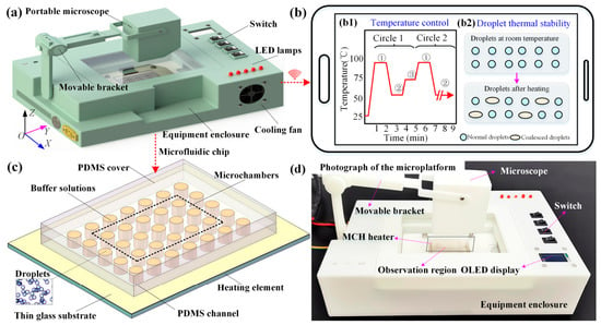
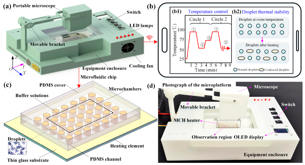
In this paper, we present a portable microfluidic platform measuring 27 cm × 18 cm × 7 cm and weighing no more than 1.5 kg, designed for high-precision thermal control in microfluidic applications (Figure 1). The platform integrates a microfluidic chip interface, a dual-mode temperature control unit combining a micro-cartridge heater (MCH) for rapid heating and a Peltier element with cooling and heat dissipation fans, and a smartphone-enabled real-time visualization system (Figure 1a,b). The chip layout and assembled setup are shown in Figure 1c and Figure 1d, respectively. An STM32 microcontroller with a positional PID algorithm regulates both constant-temperature and thermal-cycling modes, achieving ±1.5 °C accuracy, 0.1–5 °C/s tunable rates, and a robust dynamic response. Compared with our previous device [8] based on Joule heating and on/off switching, this platform adds bidirectional closed-loop control, PID-based constant-temperature and multi-stage thermal-cycling modes, synchronized smartphone/Wi-Fi visualization, and a disposable PDMS-well chip. The system costs no more than CNY 2000 (excluding the smartphone and computer) and runs on an external 36 V DC adapter, offering a compact, low-cost alternative to bulky commercial cyclers. We demonstrate its utility by evaluating the thermal stability of water-in-oil single-emulsion droplets under varying thermal conditions. This platform is also applicable to other temperature-controlled microfluidic reactions, such as nucleic acid testing, enzymatic analysis, nanomaterial synthesis, and cell culture.
Figure 1.
Schematic of the portable microfluidic platform with integrated temperature control and real-time visualization. (a) 3D model of the platform. (b) Schematic illustrating on-site monitoring of temperature and droplet states via a smartphone. (c) Layout of the microfluidic chip for droplet handling. (d) Photograph of the experimental setup.
2. Experimental Section
2.1. Materials
Phosphate-buffered saline (PBS) was purchased from Macklin Biochemical Co., Ltd. (Shanghai, China). Silicone oil (viscosity ~50 cSt), surfactant RSN-749, polydimethylsiloxane (PDMS), and its corresponding curing agent were acquired from Dow Corning Corporation (Midland, MI, USA). Tris-HCl buffer (20 mM), potassium chloride (KCl), and magnesium chloride (MgCl2) were sourced from Aladdin Biochemical Technology Co., Ltd. (Shanghai, China). Polyvinyl alcohol (PVA) was purchased from Sigma-Aldrich (Shanghai, China).
2.2. Fabrication of the Microfluidic Device for Sample Storage
The microfluidic chip used for sample storage in the thermal manipulation platform comprised three layers: a 100-μm-thick glass coverslip as the bottom layer, a 2.9-mm-thick PDMS layer containing an array of wells (each 3 mm in diameter) as the middle layer, and a PDMS cover sheet as the top layer. The bottom glass coverslip was a low-cost commercial product whose thinness facilitated efficient heat transfer from the thermal control unit to the samples, thereby ensuring effective thermal manipulation. The PDMS well layer served as the main sample-storage compartment, in which multiple independent wells were readily fabricated using a punch; this punching-based approach simplified chip fabrication and allowed the number and arrangement of storage wells to be easily adapted to different experimental needs. The PDMS well layer and the glass substrate were bonded by plasma treatment to ensure structural integrity and sealing stability during thermal operation. During experiments, droplets and suspended samples were first loaded into the wells of the PDMS layer, after which a PDMS cover sheet was placed on top to prevent evaporation and external contamination during heating. This chip architecture offers significant advantages in terms of low cost and rapid fabrication, making it well suited for portable detection and analysis.
2.3. Fabrication of Glass Capillary Device for Droplet Generation
Glass-capillary microfluidic devices were constructed for producing water-in-oil (W/O) single-emulsion droplets. The device configuration included a glass substrate, one square glass capillary, and two cylindrical glass capillaries. The square capillary (1.05 mm i.d., 1.5 mm o.d.; AIT Glass, Inc., Rockaway, NJ, USA) and the two cylindrical capillaries (0.58 mm i.d., 1.03 mm o.d.; World Precision Instruments, Inc., Sarasota, FL, USA) were mounted coaxially on the glass substrate. The inlet ends of the two cylindrical capillaries were pulled into tapers with a micropipette puller (PC-100, Narishige, Tokyo, Japan), yielding tip openings of approximately 40 μm and 125 μm in diameter, respectively. These two tapered capillaries were then aligned coaxially inside the square capillary with a spacing of 70 μm, which defined the droplet-generation region. To promote stable droplet formation, the surface wettability of the glass capillaries was selectively adjusted before device assembly. Specifically, the outer surface of the injection capillary and the inner surface of the collection capillary were hydrophobicized by soaking the targeted regions in a 2 wt% solution of n-octadecyltrimethoxysilane (OTS) in toluene for 30 s; the treated capillaries were then rinsed successively with toluene and ethanol and finally cured at 160 °C for 0.5 h. This selective hydrophobic treatment was intended to favor preferential wetting by the oil phase while suppressing water adhesion, thereby stabilizing W/O droplet generation.
2.4. Experimental Setup
During droplet generation, a dual-channel syringe pump (LSP02-3B, Ditron-tech, Baoding, China) was used to independently regulate the flow rates of the dispersed aqueous phase and the continuous oil phase, thereby allowing the droplet size and generation frequency to be controlled. The droplet formation process was monitored in real time and recorded using an inverted fluorescence microscope (BX53, Olympus, Tokyo, Japan) equipped with a CCD camera (DP-27, Olympus, Tokyo, Japan); the acquired images were used to examine droplet generation behavior and monodispersity. Subsequently, droplet stability analysis was carried out on the fabricated microfluidic platform, so that the thermal stability of the generated W/O single-emulsion droplets could be evaluated under controlled conditions.
3. Results and Discussions
3.1. Hardware Architecture of the Integrated Temperature-Control Platform
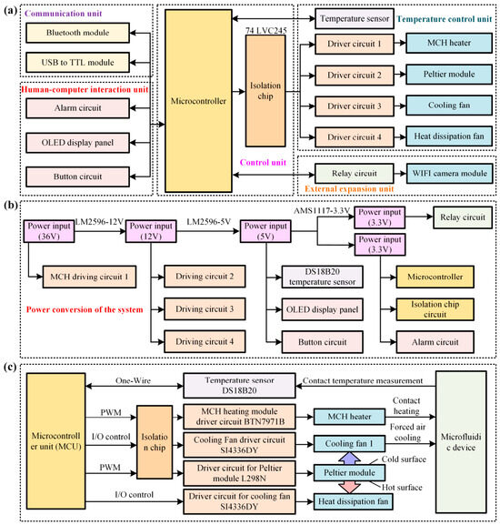
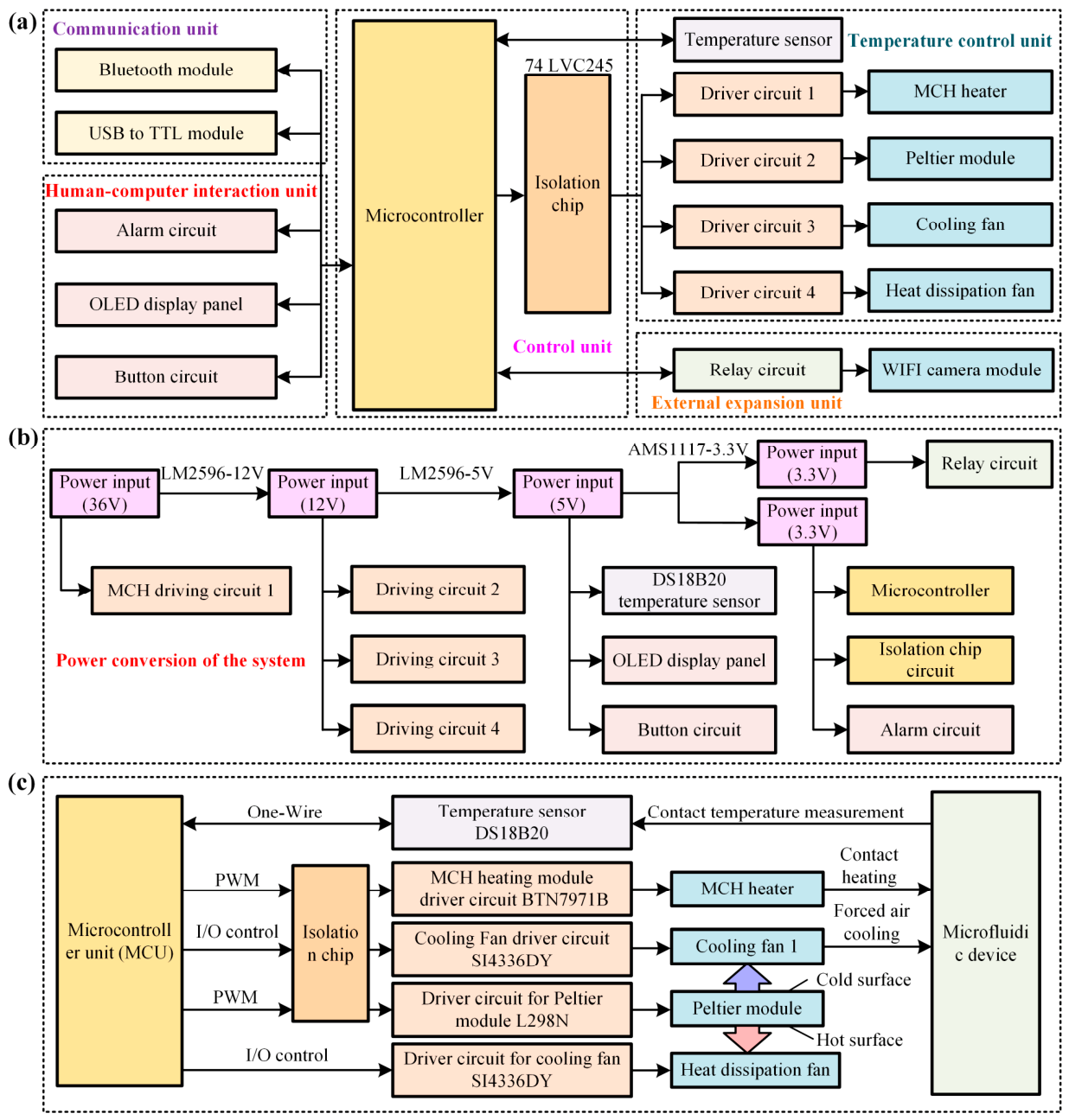
For the microfluidic platform in this study, a dedicated hardware architecture integrating all functional modules is designed to coordinate temperature acquisition, heating/cooling regulation, and external video capture and transmission, as illustrated in Figure 2a. Specifically, the hardware system is organized into five functional modules: communication, human–computer interaction, main control, temperature control, and external expansion. This modular arrangement allows each unit to perform a well-defined task while remaining coordinated through the main control unit, thereby simplifying system integration, debugging, and future functional extension. The communication unit includes a Bluetooth module for wireless remote monitoring and control via a smartphone, and a USB-to-TTL module for wired program writing and debugging with a computer, thus providing both wireless and wired links for different operational scenarios. The human–computer interaction unit comprises an alarm circuit, an OLED display, and a keypad circuit. Real-time temperature data, PWM values, and PID parameters are shown on the OLED display; a buzzer triggers an audible alert when temperature overshoot exceeds a preset threshold; and the keypad circuit enables program start, stop, and reset, allowing local operation and immediate status feedback without relying on external devices. The main control unit is built around an STM32 microcontroller and a logic gate chip. The microcontroller processes information and outputs control signals to actuators, while the logic gate chip, placed between the DC drive circuits and the I/O ports, protects against reverse current damage and thus enhances hardware reliability. The temperature control unit achieves precise regulation using a temperature sensor, an MCH heating element, and a fan that directs cool air from a thermoelectric cooler to the target area, forming a closed-loop thermal regulation path. The external expansion unit consists of a relay circuit and a Wi-Fi camera module. The main control unit switches the camera via the relay; once powered, video data are transmitted directly to the host computer through the Wi-Fi module without consuming microcontroller resources, enabling real-time monitoring of the experimental area while preserving the main controller for thermal regulation tasks.
Figure 2.
Hardware implementation of the temperature control system. (a) System block diagram showing power supply, microcontroller unit (MCU), temperature control unit, human–machine interface, and communication modules. (b) Three-stage voltage conversion chain supplying power to all onboard components. (c) Actuation scheme for bidirectional temperature regulation.
To support the coordinated operation of these functional modules, the system incorporates a power conversion module for voltage regulation and filtering (Figure 2b). The power adapter supplies 36 V DC, which directly powers the MCH heating element driver and is stepped down to 12 V DC via an LM2596-12V-based regulator for primary regulation. This 12 V supply powers the cooling fan, the thermoelectric cooler fan, and the thermoelectric cooler driver. The 12 V DC is further stepped down to 5 V DC through an LM2596-5V-based regulator for secondary regulation, providing power to the temperature sensor, Bluetooth module, OLED display, keypad circuit, and alarm circuit. Finally, an AMS1117-3V3-based regulator generates two independent 3.3 V DC lines for tertiary regulation: one for the microcontroller and logic gate chip, and the other (relay-controlled) for the Wi-Fi camera module.
Building upon this power infrastructure, the temperature control unit serves as the core of system functionality, enabling both thermal self-stabilization and thermal cycling (Figure 2c). The main microcontroller receives real-time temperature data and coordinates the unit’s operation. For heating, it outputs a PWM waveform to the MCH driver, which powers the heater at a defined level; heat is then transferred to the microfluidic chip via thermal contact. For cooling, the microcontroller outputs a PWM waveform to the thermoelectric cooler driver, activates the cooler, and sets the I/O pins high to engage both the cooling fan and the heat dissipation fan. The cooling fan directs cold-side air toward the chip, while the heat dissipation fan exhausts hot-side heat, ensuring sustained cooling performance. Once all the modules and their associated hardware circuits are interconnected, the complete system is assembled. The outer casing and supporting framework of the system are fabricated using 3D printing.
To meet ambient temperature requirements, the platform supports both heating and cooling self-stabilization. The heating phase relies primarily on the MCH, while cooling depends on the coordinated operation of the Peltier module and fans. Maintaining a setpoint or switching between temperatures requires close collaboration between the PID algorithm and these actuating components. Although the individual components can support a wider range, the validated operating window was intentionally limited to 20–95 °C for aqueous systems, because approaching 100 °C at ambient pressure would cause evaporation and boiling that compromise droplet stability and chip sealing. Within this window, stable constant-temperature and thermal-cycling control is achieved.
3.2. Temperature Control Strategy and Thermal Performance
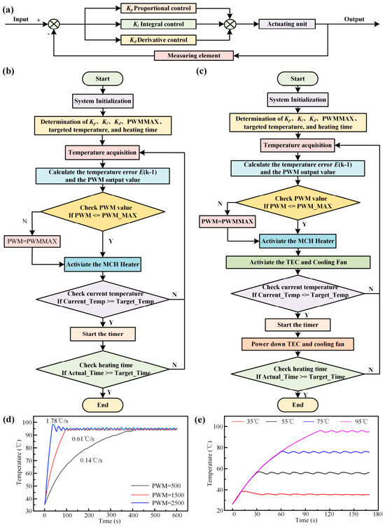
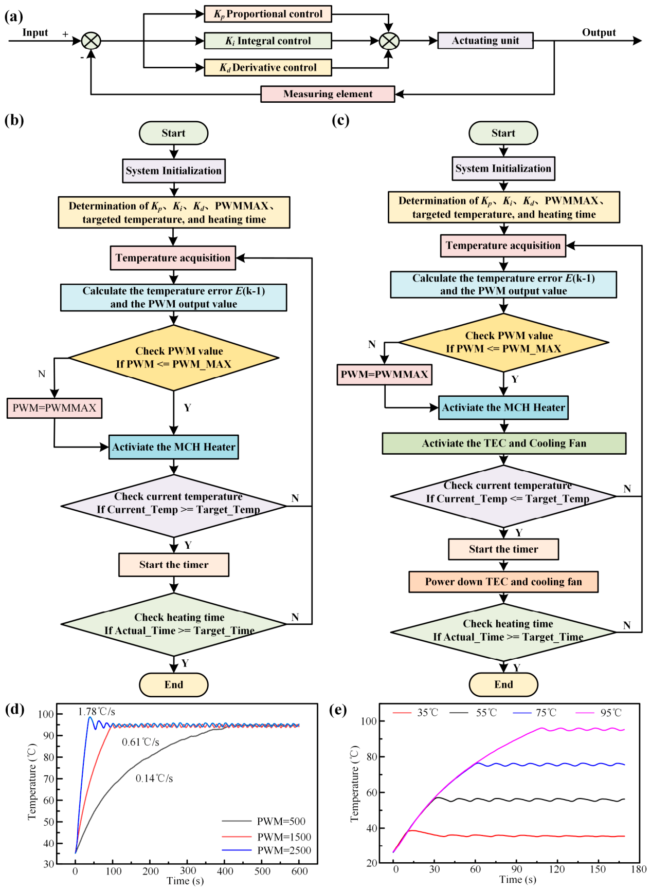
The hardware modules described above provide the physical basis for heating and cooling, but they alone cannot ensure stable setpoint tracking, rapid mode switching, or effective suppression of overshoot; precise temperature regulation therefore depends on how these components are coordinated by the control algorithm. To achieve the close collaboration between the internal PID algorithm and the actuating components—namely, the MCH, Peltier module, cooling fan, and heat dissipation fan—we adopt a PID controller, a widely used control strategy illustrated in Figure 3a. Its core principle is to achieve precise regulation of the target variable using the proportional (Kp), integral (Ki), and derivative (Kd) terms. PID controllers generally exist in two forms: positional and incremental. Since the primary physical parameter controlled by our platform is temperature and high precision is required, we selected the positional PID algorithm. Its basic principle is to adjust the control variable so that the system output follows the target value. The specific implementation is detailed in Equations (1) and (2).
u(k) = Kpe(k) + KiΣe(i) + Kd[e(k) − e(k − 1)]
Figure 3.
PID control schemes and constant-temperature performance. (a) PID closed-loop control schematic. (b) Flowchart of heating to target temperature followed by PID stabilization. (c) Flowchart of active cooling to target temperature followed by stabilization. (d) Surface temperature evolution of the MCH under different heating rates to 95 °C. (e) Surface temperature evolution of the MCH at different target temperatures.
The algorithm compares the user-defined target value with the real-time state of the controlled plant to obtain the deviation from the desired setpoint, denoted as e(k). Simultaneously, it accumulates the errors e(k), e(k − 1), …, e(1) to compute the error sum, and calculates the difference between the two most recent deviations as e(k) − e(k − 1). These three error terms are then combined in a weighted manner using the corresponding parameters Kp, Ki, and Kd to generate a control signal that regulates the plant.
The flowcharts of the control algorithms for temperature rise followed by stabilization and for temperature decrease followed by stabilization are shown in Figure 3b and Figure 3c, respectively. Although the two procedures involve different actuating paths-heating via the MCH and cooling via the thermoelectric cooler and fans, they share the same basic control sequence. Regardless of whether the system performs temperature-rise self-stabilization or temperature-drop self-stabilization, it must first initialize its internal clock, PWM functionality, communication modules, and other components. This initialization step establishes a stable time base, configures the PWM channels for subsequent actuator control, and ensures reliable communication between the microcontroller and the peripheral modules before closed-loop regulation begins. Next, the system receives and assigns key parameters, including the Kp, Ki, and Kd coefficients, the target temperature, the maximum PWM duty cycle (PWMmax), and the heating duration for each stage. These parameters define the control behavior, constrain the maximum actuation output, and determine how long each stage is maintained. After completing these internal preparations, the system communicates with the DS18B20 temperature sensor to acquire real-time temperature data. Once the real-time temperature is obtained, the system computes the deviation between the measured temperature and the target value and calculates the control signal using the positional PID algorithm. The resulting control signal is then converted into an adjusted PWM output, which is delivered to the corresponding driver circuit to regulate the heating or cooling actuator. This measurement-calculation-actuation loop is repeated during operation, allowing the system to continuously correct the temperature toward the setpoint and maintain stable thermal conditions.
Following this PID-based control logic, when executing the temperature-rise self-stabilization procedure, where the target holding temperature is above ambient, the system outputs the adjusted PWM waveform to the drive circuit to activate the heating element. Once the experimental area reaches the target temperature, the system timer begins recording the heating duration. During this period, the heating element produces a temperature-rising effect that counteracts natural cooling, thereby achieving temperature self-stabilization. Conversely, during the temperature-drop self-stabilization procedure, the system activates the semiconductor cooler and fan, directing cool air over the experimental area to lower the temperature from an elevated value to the set self-stabilizing temperature. Because this self-stabilizing temperature remains above ambient, the system deactivates the cooler and fan once the timer starts counting. Temperature self-stabilization is then maintained through the interplay between periodic heating and natural cooling.
Based on the above control operations, the system integrates heaters, thermoelectric coolers, cooling fans, and temperature sensors with a PID algorithm to enable flexible and programmable temperature regulation. The heating and cooling rates can be precisely tuned within 0.1–5 °C/s. Taking the mode of heating from room temperature to a preset target followed by constant-temperature maintenance as an example, the ramping rate is freely adjustable by modulating the maximum PWM duty cycle. Figure 3d shows the heater surface temperature during ramping from room temperature to 95 °C at three distinct rates (0.14, 0.61, and 1.78 °C/s), followed by stable isothermal holding. The maximum temperature deviation throughout the stabilization stage is below 3%, confirming the high precision and excellent reliability of the temperature control module. Figure 3e presents temperature profiles acquired during heating from room temperature to multiple target points; negligible overshoot is observed in all cases, and stable thermal equilibrium is maintained at each set temperature. These results further validate the outstanding steady-state control performance of the developed platform.
After the platform achieves automatic temperature stabilization in both heating and cooling modes, we further conducted dynamic temperature regulation experiments to verify the flexibility of its thermal manipulation. A typical three-step thermal cycling protocol resembling that used in PCR was adopted as a representative validation model, consisting of an initial preheating stage, a thermal cycling stage, and a final holding stage. The preheating and holding stages operate at constant temperatures, whereas the thermal cycling stage involves continuous alternating temperature changes. Specifically, the preheating stage is set to temperature T1 and is considered complete once the system reaches T1 and maintains it for a preset duration t1. The system then enters the thermal cycling stage, which includes two sub-stages commonly used in PCR-like protocols. First, the target temperature is set to T2-1; the heater warms the experimental region, which is then held at T2-1 for t2-1. Next, the target temperature is adjusted to T2-2 (lower than the current real-time temperature), activating the thermoelectric cooler and cooling fans to reduce the temperature of the region. After reaching T2-2, the cooling components are deactivated, and the temperature is maintained for t2-2. Each complete cycle of these two sub-stages increments the cycle counter by one. When the counter reaches the preset number of cycles, the system transitions to the holding stage (set to T3), which ends after maintaining T3 for t3. In practice, the temperature and time parameters for each stage, as well as the number of sub-stages and cycles, can be flexibly configured according to experimental requirements.
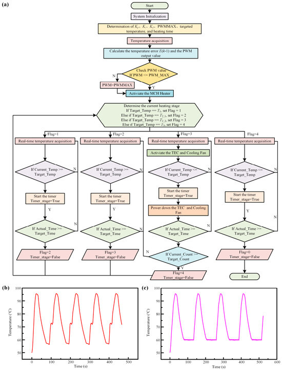
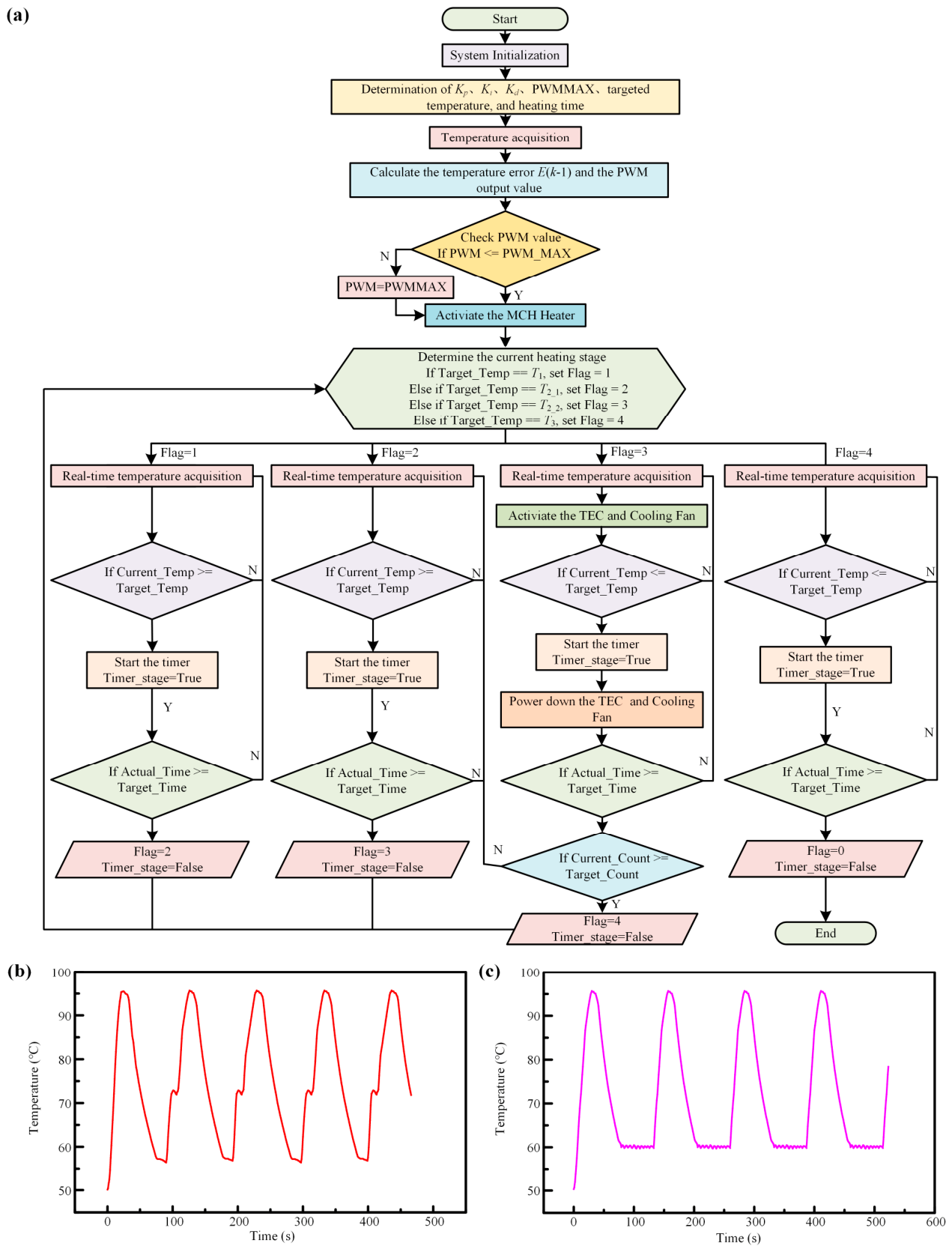
Dynamic temperature control of PCR-like protocols is inherently complex, involving stage-specific temperature and time settings, continuous alternating heating/cooling stabilization during thermal cycling, and real-time cycle counting. To address these challenges, the system program integrates a temperature-stage control thread and a timer thread that work synergistically to execute the entire programmed thermal cycling process with high reliability. As illustrated in Figure 4a, a Flag bit is defined to distinguish between different temperature control stages based on its assigned value, while a Timer_stage bit monitors the timing status of each stage. Upon system startup, the internal clock and all functional components are initialized, followed by the reception of operational parameters from the host computer. After validating these parameters, the control system communicates with the temperature sensor to acquire real-time temperature data at 1-s intervals, updating the current temperature variables and synchronously transmitting them back to the host computer. Using both the real-time and target temperatures, the system calculates the corresponding PWM signal via the PID algorithm and outputs it to regulate the heater. The Flag bit is initially set to 1, corresponding to the preheating stage. When the real-time temperature first meets or exceeds the target temperature, the Timer_stage bit is activated to start timing. Once the preset holding duration is reached, the Flag bit switches to 2 and the Timer_stage bit is reset, enabling a smooth transition to the first sub-stage of thermal cycling while clearing the timer. During the thermal cycling phase, the system continuously performs heating and cooling stabilization cycles. Each alternating execution of these two stabilization processes increments the thermal cycling count by one. When the count reaches the preset threshold, the thermal cycling stage concludes and the Flag bit switches to 4. Through this Flag bit mechanism, the system accurately determines the reaction status, temperature setpoint, and timer state, thereby enabling sequential and automated execution of all programmed stages.
Figure 4.
Programmed thermal cycling control strategy resembling PCR. (a) Flowchart of the proposed control algorithm for programmed thermal cycling. (b) Typical three-step thermal cycling profile resembling PCR. (c) Typical two-step thermal cycling profile resembling PCR.
Figure 4b,c illustrate the temperature variation characteristics of the MCH surface under three-stage and two-stage thermal cycling programs that mimic the temperature sequence commonly used in PCR, respectively. It should be noted that no actual PCR amplification was performed in this study; these PCR-like thermal programs were used solely to examine the dynamic temperature control capability of the platform. The heater surface temperature responds rapidly to the system’s control signals, exhibiting no obvious overshoot or undershoot during temperature switching and maintaining excellent stability throughout each holding period. These results indicate that the platform can execute repeated heating–cooling–holding sequences with well-controlled transitions and stable isothermal segments. This outstanding dynamic performance further confirms the high flexibility and reliability of the developed platform in temperature control. It not only supports various programmed thermal cycling protocols but also lays a solid foundation for a range of microfluidic applications that demand precise and flexible heating, including nucleic acid detection, protein denaturation, and cell culture.
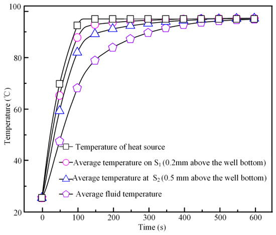
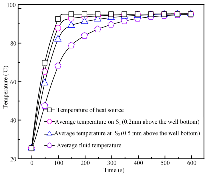
While Figure 3 and Figure 4 confirm that the heater-surface temperature can be precisely programmed and stabilized in both constant-temperature and thermal-cycling modes, they do not directly indicate the temperature experienced by the liquid sample. To assess this relationship, a representative heating-and-holding process corresponding to the ramp-and-hold condition in Figure 3d was examined by transient finite-element simulation. This simulation does not reproduce the full heating–cooling cycles in Figure 4; rather, it provides a basis for interpreting the thermal lag between the heater-surface and sample temperatures under representative operating conditions. Specifically, the simulations were performed in COMSOL 6.2 using a three-layer model (100-µm glass substrate, 2.9-mm-thick PDMS well layer with 3-mm-diameter wells, and PDMS cover), with a prescribed heater boundary at the bottom glass surface and a mesh-independence check. Temperature evolution was monitored at the well bottom, 0.2 and 0.5 mm above it, and as the volume-averaged fluid temperature. When the heater-surface temperature was ramped from 20 to 95 °C at 0.61 °C/s, it stabilized within approximately 100–110 s (Figure 5). After stabilization, the volume-averaged liquid temperature reached about 80% of the heater-surface temperature, the fluid temperature on surface S2 (0.5 mm above the well bottom) about 90%, and the fluid temperature on surface S1 (0.2 mm above the well bottom) closely matched the heater-surface temperature. These results indicate that the solution temperature follows the heater-surface temperature more closely as the channel dimension decreases, since smaller depths or volumes reduce the liquid’s thermal resistance and heat capacity and shorten the thermal lag. For the present 2.9-mm-deep wells, close tracking is already achieved near the well bottom; further reducing the well depth or channel height should improve the volume-averaged temperature response under rapid thermal transitions.
Figure 5.
Simulated transient temperature response of the liquid in the microfluidic chip during heating from room temperature to 95 °C at 0.61 °C/s.
Having characterized both the steady-state and dynamic thermal performance of the platform, it is useful to place its specifications in the context of commercial thermal cyclers. Commercial benchtop thermal cyclers used for PCR typically offer temperature accuracy of ±0.25–0.5 °C and sample ramp rates of approximately 1.6–4.4 °C/s, but such instruments are generally expensive and bulky. Although the ±1.5 °C accuracy of the present platform is coarser than that of these high-end systems, it should be viewed in the context of a low-cost, portable design. For many of the applications targeted here, including the droplet thermal stability assessment demonstrated in this work, this level of accuracy is adequate, while the rate range of 0.1–5 °C/s is comparable to that of typical benchtop cyclers. The platform is therefore not intended to replace high-end PCR instruments but to provide a practical alternative for cost-sensitive and field-deployable scenarios, where portability, low cost, bidirectional rate control, and integrated visualization are more important than ultimate temperature accuracy.
3.3. The Application of the Platform on Droplet Thermal Stability Analysis
The practical value of the platform was examined by probing the thermal stability of silicone oil-based water-in-oil droplets. Such droplets are attractive as miniature reaction compartments because of their small dimensions, low cross-contamination risk, and high detection sensitivity, and are promising for biochemical analysis and materials synthesis. However, they are thermodynamically metastable, with stability influenced by the oil and aqueous phases, surfactant type and concentration, and droplet density, viscosity, interfacial tension, and size. Heating induces temperature-dependent changes in these properties and can generate buoyancy- and capillary-driven convective flows, together weakening droplet stability. Since many biochemical and materials-synthesis reactions, including PCR assays, require thermal activation, characterizing droplet thermal response and identifying suitable formulation and structural parameter windows are important prerequisites for preparing thermally stable droplets.
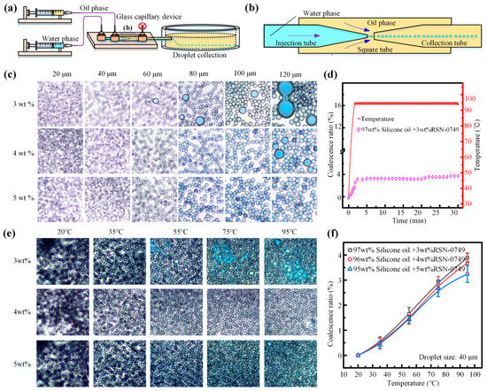
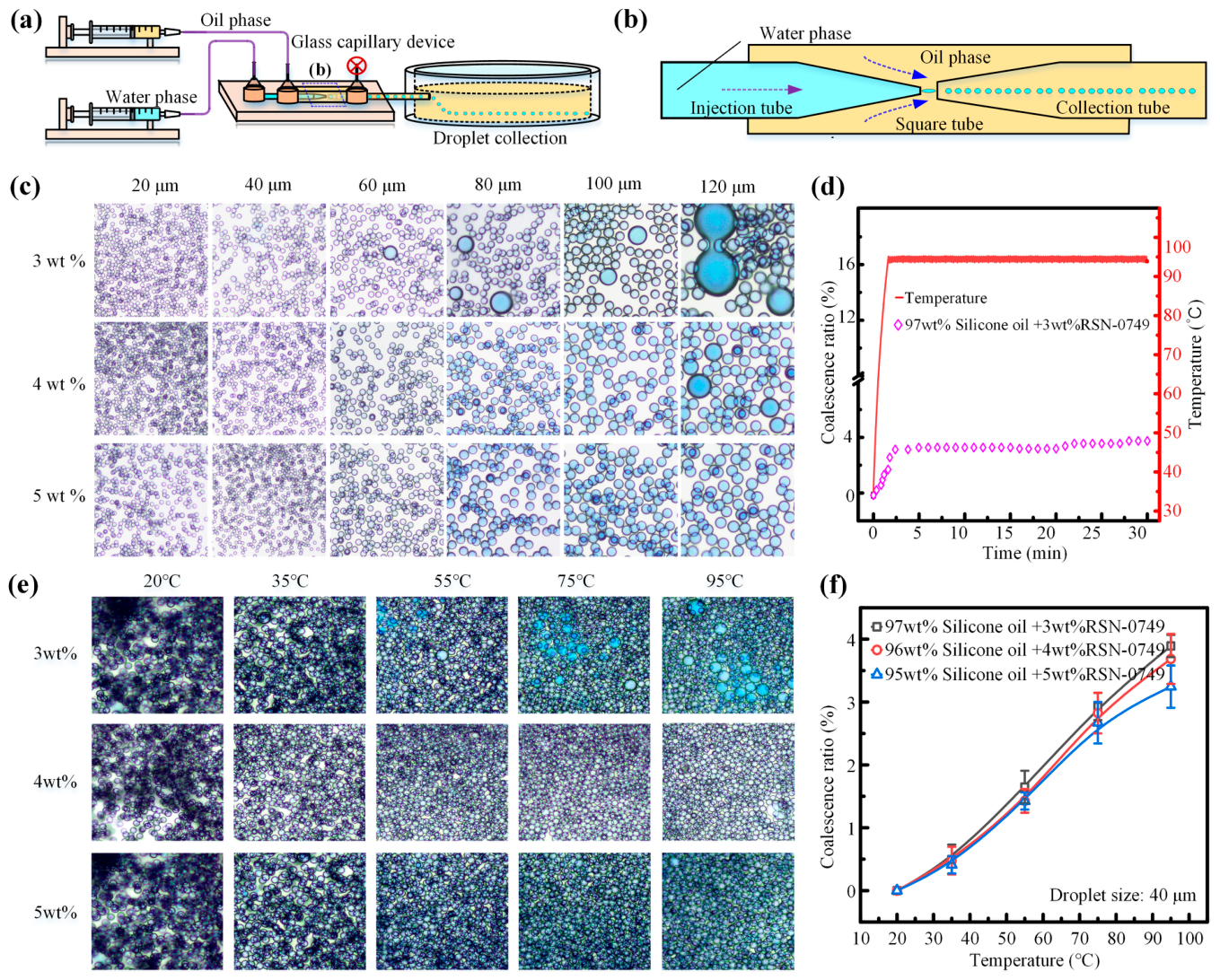
To systematically explore this parameter space, water-in-oil droplets were prepared using a glass capillary chip, as illustrated in Figure 6a,b. The oil and aqueous phases were introduced separately into the chip by syringe pumps, and the inner aqueous phase was dispersed into uniform droplets under the combined action of shear force and interfacial tension exerted by the outer continuous phase. Silicone oil (viscosity ~50 cSt) containing RSN-749 as the surfactant served as the continuous phase, while the inner phase consisted of PVA (3 wt%), Tris-HCl (20 mmol/L), KCl (50 mmol/L), and MgCl2 (5 mmol/L), a composition chosen to mimic a standard PCR reaction buffer so that the thermal-stability results would be relevant to droplet-based nucleic acid amplification. This approach allowed droplets to be generated reproducibly, providing a basis for examining how formulation and droplet size influence emulsion stability. The droplets showed a relatively uniform size distribution at room temperature, facilitating consistent comparison of coalescence behavior. Droplet morphology at room temperature is shown in Figure 6c. Here, the coalescence ratio was calculated as the number of coalesced droplets divided by the total number of droplets in each field of view, based on at least three independent experiments. The results indicate that the coalescence ratio decreases with increasing surfactant concentration but increases with increasing droplet size. This behavior can be primarily explained by two mechanisms. First, a higher surfactant concentration lowers the interfacial tension and strengthens steric or electrostatic repulsion at the interface, thereby suppressing coalescence. Conversely, larger droplets undergo longer film drainage times and are therefore more susceptible to interfacial rupture upon collision, which substantially increases the likelihood of coalescence. These trends suggest that both surfactant dosage and droplet size are important parameters for tuning the stability of microdroplets.
Figure 6.
Thermal stability of water-in-oil droplets with a silicone oil/RSN-749 mixture as the oil phase. (a,b) Schematic illustrations of the glass capillary device employed for droplet generation. (c) Droplet states at room temperature when the oil phase consists of silicone oil and RSN-749. (d) Time-dependent droplet coalescence ratio during heating from 20 °C to 95 °C at a ramp rate of 0.61 °C/s and during the subsequent 30-min isothermal hold. (e) Droplet states observed at different temperatures during heating at a ramp rate of 0.61 °C/s. (f) Effect of RSN-749 concentration in the oil phase on the thermal stability of water-in-oil droplets.
Then we transferred the room-temperature-stable droplets to the experimental setup for systematic assessment of their thermal stability. Using a heating protocol that raised the heater surface temperature from 20 °C to 95 °C at a constant ramp rate of 0.61 °C/s, followed by a 30-min isothermal hold (Figure 6d), we recorded the coalescence ratio of the silicone oil-based droplets (e.g., 95 wt% silicone oil +5 wt% RSN-749). These droplets exhibited only limited coalescence during the ramping stage, with the coalescence ratio remaining below approximately 3.5% across 20–95 °C, and no significant further increase was observed once the temperature stabilized. A consistent trend was that coalescence events were largely concentrated in the transient heating phase, while coalescence after reaching thermal equilibrium remained low (≤2%), suggesting that temperature variation, rather than sustained high-temperature conditions, may be a major factor contributing to droplet coalescence. One plausible explanation for this behavior is that temperature gradients formed during heating may initiate thermal buoyancy–capillary convection, thereby enhancing droplet movement and interfacial flow and facilitating coalescence; however, direct evidence for this mechanism is not yet available and further verification is required. Under the same heating protocol, we further characterized the thermal stability of silicone oil droplets at different surfactant concentrations; Figure 6e presents their thermal stability states, while Figure 6f provides the corresponding quantitative data. As the target temperature increases, the duration of the temperature ramp prolongs, leading to a longer period of thermal buoyancy–capillary convection, while higher temperatures induce more pronounced changes in physicochemical properties such as viscosity, interfacial tension, and surfactant activity; collectively, these factors may contribute to an increased coalescence ratio. Conversely, increasing the surfactant concentration reduces interfacial tension and enhances disjoining pressure and repulsive interactions between interfaces, thereby raising the energy barrier for coalescence and resulting in a decreased coalescence ratio. Overall, these observations highlight that achieving thermally stable water-in-oil droplets requires careful optimization of multiple parameters, including minimizing droplet size and judiciously selecting oil phases and surfactant systems.
4. Conclusions and Outlook
In this work, we have developed a portable, integrated microfluidic platform that combines high-precision bidirectional temperature control, real-time visualization, and disposable microfluidic chips into a compact, low-cost system measuring 27 cm × 18 cm × 7 cm, weighing no more than 1.5 kg, and costing no more than CNY 2000. The thermal control module, built around a micro-cartridge heater, a Peltier element, a cooling fan, and an STM32 microcontroller implementing a positional PID algorithm, achieves a steady-state temperature accuracy of ±1.5 °C and adjustable heating/cooling rates of 0.1–5 °C/s, with excellent dynamic performance under PCR-like programmed thermal cycling protocols. As a representative heat-sensitive microfluidic application, we used this platform to investigate the thermal stability of silicone oil-based water-in-oil droplets. Systematic analysis suggested that droplet coalescence tended to be more pronounced during temperature ramping than during isothermal holding, and the silicone oil/RSN-749 system maintained a low coalescence ratio across 20–95 °C. Therefore, this work provides a well-characterized, user-friendly, and truly portable thermal manipulation platform for temperature-controlled microfluidic reactions. Its versatility in constant-temperature and thermal-cycling modes, combined with real-time visualization and low cost, makes it a practical solution for potential applications such as point-of-care nucleic acid testing, high-throughput screening, and on-site material synthesis. We anticipate that this platform will significantly lower the barrier to adopting temperature-controlled microfluidic systems in routine laboratory and field settings.
In future work, the thermal stability of other droplet systems with different oil phases, surfactants, and dispersed-phase compositions should be systematically examined to broaden the design space for thermally robust formulations. More in-depth application studies are also needed, including integration with actual PCR and other nucleic-acid amplification assays, as well as exploration of enzymatic reactions, nanomaterial synthesis, and cell-based assays. At the hardware level, the system could be adapted to DC power supply to reduce dependence on AC mains and improve field portability. These efforts would clarify the platform’s practical limits and guide improvements in thermal uniformity, chip integration, and system-level automation.
Author Contributions
Conceptualization, methodology, software, formal analysis, K.Z. and W.X.; writing—original draft preparation, K.Z.; writing—review and editing, K.Z. and A.H.; funding acquisition, K.Z. All authors have read and agreed to the published version of the manuscript.
Funding
This work was financially supported by the Natural Science Foundation of China (12302351), the Medicine & Engineering & Informatics Fusion and Transformation Key Laboratory of Luzhou City (XGY202406), and the Fundamental Research Funds for the Central Universities (2572024DY05).
Institutional Review Board Statement
Not applicable.
Informed Consent Statement
Not applicable.
Data Availability Statement
The original contributions presented in this study are included in the article. Further inquiries can be directed to the corresponding authors.
Conflicts of Interest
The authors declare no conflict of interest.
References
- Zhang, K.; Cai, C.; Sun, H.; Wu, Y.; Xie, Z. Flexible modulation of droplet concentrations via AC electrothermal flow for fabrication of crystalline drug particles. Sens. Actuators B Chem. 2025, 444, 138486. [Google Scholar] [CrossRef] [Scilit]
- Li, G.; Zhou, Z.; Xu, X.; Yang, X.; Cui, M.; Ruan, Z.; Wu, S.; Dong, S.; Luo, J.; Cao, Z. Massive and controllable production of droplets on chips induced by surface acoustic waves for multiplex digital PCR detection of bacteria. Sens. Actuators B Chem. 2026, 446, 138763. [Google Scholar] [CrossRef] [Scilit]
- Zhang, K.; Sun, M.; Jia, N.; Xing, F.; Xie, Z. Electrically-Controlled Multifunctional Double-Emulsion Droplet Carrier Manipulation. Adv. Funct. Mater. 2025, 35, e10679. [Google Scholar] [CrossRef] [Scilit]
- Jiang, Z.; Shi, H.; Tang, X.; Qin, J. Recent advances in droplet microfluidics for single-cell analysis. TrAC Trends Anal. Chem. 2023, 159, 116932. [Google Scholar] [CrossRef] [Scilit]
- Yu, M.; Xie, Z.; Hou, L.; Liu, J.; Zhang, K. Controllable Double-Emulsion Droplet Manipulation Actuated by a Triboelectric Nanogenerator. Adv. Funct. Mater. 2024, 34, 2408095. [Google Scholar] [CrossRef] [Scilit]
- Zhu, J.; Meng, Y.; Gao, W.; Yang, S.; Zhu, W.; Ji, X.; Zhai, X.; Liu, W.Q.; Luo, Y.; Ling, S.; et al. AI-driven high-throughput droplet screening of cell-free gene expression. Nat. Commun. 2025, 16, 2720. [Google Scholar] [CrossRef] [Scilit] [PubMed]
- Wu, J.; Hwang, Y.H.; Yadavali, S.; Lee, D.; Issadore, D.A. Micro-Patterning Wettability in Very Large Scale Microfluidic Integrated Chips for Double Emulsion Generation. Adv. Funct. Mater. 2023, 34, 2309718. [Google Scholar] [CrossRef] [Scilit]
- Zhang, K.; Xiang, W.; Jia, N.; Yu, M.; Liu, J.; Xie, Z. A portable microfluidic device for thermally controlled granular sample manipulation. Lab A Chip 2024, 24, 549–560. [Google Scholar] [CrossRef] [Scilit] [PubMed]
- Han, S.; An, H.J.; Kwak, T.; Kim, M.; Kim, D.; Lee, L.P.; Choi, I. Plasmonic Optical Wells-Based Enhanced Rate PCR. Nano Lett. 2024, 24, 1738–1745. [Google Scholar] [CrossRef] [Scilit] [PubMed]
- Xu, D.; Zhang, W.; Li, H.; Li, N.; Lin, J.-M. Advances in droplet digital polymerase chain reaction on microfluidic chips. Lab A Chip 2023, 23, 1258–1278. [Google Scholar] [CrossRef] [Scilit] [PubMed]
- Lan, F.; Demaree, B.; Ahmed, N.; Abate, A.R. Single-cell genome sequencing at ultra-high-throughput with microfluidic droplet barcoding. Nat. Biotechnol. 2017, 35, 640–646. [Google Scholar] [CrossRef] [Scilit] [PubMed]
- Zhang, K.; Xiang, W.; Liu, J.; Xie, Z. Flexible droplet transportation and coalescence via controllable thermal fields. Anal. Chim. Acta 2023, 1277, 341669. [Google Scholar] [CrossRef] [Scilit] [PubMed]
- Zhang, K.L.; Ren, Y.K.; Hou, L.K.; Tao, Y.; Liu, W.Y.; Jiang, T.Y.; Jiang, H.Y. Continuous microfluidic mixing and the highly controlled nanoparticle synthesis using direct current-induced thermal buoyancy convection. Microfluid. Nanofluidics 2020, 24, 1. [Google Scholar] [CrossRef] [Scilit]
- Urrutia Gómez, J.E.; Zhou, M.; Mandsberg, N.K.; Serna, J.A.; von Padberg, J.; Liu, S.; Reischl, M.; Levkin, P.A.; Popova, A.A. Highly Parallel and High-Throughput Nanoliter-Scale Liquid, Cell, and Spheroid Manipulation on Droplet Microarray. Adv. Funct. Mater. 2024, 35, 2410355. [Google Scholar] [CrossRef] [Scilit]
- Shahbazi, M.; Jager, H.; Mohammadi, A.; Asghartabar Kashi, P.; Chen, J.; Ettelaie, R. 3D Printing of Bioactive Gel-like Double Emulsion into a Biocompatible Hierarchical Macroporous Self-Lubricating Scaffold for 3D Cell Culture. ACS Appl. Mater. Interfaces 2023, 15, 49874–49891. [Google Scholar] [CrossRef] [Scilit] [PubMed]
- Sart, S.; Ronteix, G.; Jain, S.; Amselem, G.; Baroud, C.N. Cell Culture in Microfluidic Droplets. Chem. Rev. 2022, 122, 7061–7096. [Google Scholar] [CrossRef] [Scilit] [PubMed]
- Tea, L.; Renou, F.; Benyahia, L.; Nicolai, T. Assessment of the stability of water in water emulsions using analytical centrifugation. Colloids Surf. A Physicochem. Eng. Asp. 2021, 608, 125619. [Google Scholar] [CrossRef] [Scilit]
- An, C.; Zhang, Y.; Li, H.; Zhang, H.; Zhang, Y.; Wang, J.; Zhang, Y.; Cheng, F.; Sun, K.; Wang, H. Thermo-responsive fluorinated surfactant for on-demand demulsification of microfluidic droplets. Lab A Chip 2021, 21, 3412–3419. [Google Scholar] [CrossRef] [Scilit] [PubMed]
- Low, L.E.; Siva, S.P.; Ho, Y.K.; Chan, E.S.; Tey, B.T. Recent advances of characterization techniques for the formation, physical properties and stability of Pickering emulsion. Adv. Colloid Interface Sci. 2020, 277, 102117. [Google Scholar] [CrossRef] [Scilit] [PubMed]
- Sharma, T.; Kumar, G.S.; Chon, B.H.; Sangwai, J.S. Thermal stability of oil-in-water Pickering emulsion in the presence of nanoparticle, surfactant, and polymer. J. Ind. Eng. Chem. 2015, 22, 324–334. [Google Scholar] [CrossRef] [Scilit]
- Miralles, V.; Huerre, A.; Malloggi, F.; Jullien, M.C. A Review of Heating and Temperature Control in Microfluidic Systems: Techniques and Applications. Diagnostics 2013, 3, 33–67. [Google Scholar] [CrossRef] [Scilit] [PubMed]
- Dos-Reis-Delgado, A.A.; Carmona-Dominguez, A.; Sosa-Avalos, G.; Jimenez-Saaib, I.H.; Villegas-Cantu, K.E.; Gallo-Villanueva, R.C.; Perez-Gonzalez, V.H. Recent advances and challenges in temperature monitoring and control in microfluidic devices. Electrophoresis 2023, 44, 268–297. [Google Scholar] [CrossRef] [Scilit] [PubMed]
- Sarbaland, F.b.N.; Kobayashi, M.; Tanaka, D.; Fujita, R.; Tanaka, N.; Furuya, M. Temperature Control in Microfluidic Devices: Approaches, Challenges, and Future Directions. Appl. Sci. 2025, 15, 9902. [Google Scholar] [CrossRef] [Scilit]
- Chan, K.; Wong, P.Y.; Yu, P.; Hardick, J.; Wong, K.Y.; Wilson, S.A.; Wu, T.; Hui, Z.; Gaydos, C.; Wong, S.S. A Rapid and Low-Cost PCR Thermal Cycler for Infectious Disease Diagnostics. PLoS ONE 2016, 11, e0149150. [Google Scholar] [CrossRef] [Scilit] [PubMed]
- Shrestha, K.; Farhana, F.Z.; Koo, K.M.; Darwish, N.; Ross, A.G.; Shiddiky, M.J.A. Challenges in the Development and Implementation of Point-of-Care Handheld qPCR Devices. Small 2026, 22, e06233. [Google Scholar] [CrossRef] [Scilit] [PubMed]
- Shen, Y.; Yalikun, Y.; Aishan, Y.; Tanaka, N.; Sato, A.; Tanaka, Y. Area cooling enables thermal positioning and manipulation of single cells. Lab A Chip 2020, 20, 3733–3743. [Google Scholar] [CrossRef] [Scilit] [PubMed]
- Li, Z.; Liu, J.; Wang, P.; Tao, C.; Zheng, L.; Sekine, S.; Zhuang, S.; Zhang, D.; Yamaguchi, Y. Multiplex amplification of target genes of periodontal pathogens in continuous flow PCR microfluidic chip. Lab A Chip 2021, 21, 3159–3164. [Google Scholar] [CrossRef] [Scilit] [PubMed]
- Miao, G.; Zhang, L.; Zhang, J.; Ge, S.; Xia, N.; Qian, S.; Yu, D.; Qiu, X. Free convective PCR: From principle study to commercial applications—A critical review. Anal. Chim. Acta 2020, 1108, 177–197. [Google Scholar] [CrossRef] [Scilit] [PubMed]
- Dinh, T.; Phan, H.P.; Kashaninejad, N.; Nguyen, T.K.; Dao, D.V.; Nguyen, N.T. An On-Chip SiC MEMS Device with Integrated Heating, Sensing, and Microfluidic Cooling Systems. Adv. Mater. Interfaces 2018, 5, 1800764. [Google Scholar] [CrossRef] [Scilit]
- Zhang, K.; Ren, Y.; Tao, Y.; Deng, X.; Liu, W.; Jiang, T.; Jiang, H. Efficient particle and droplet manipulation utilizing the combined thermal buoyancy convection and temperature-enhanced rotating induced-charge electroosmotic flow. Anal. Chim. Acta 2020, 1096, 108–119. [Google Scholar] [CrossRef] [Scilit] [PubMed]
- Zhang, K.; Ren, Y.; Zhao, M.; Jiang, T.; Hou, L.; Jiang, H. Flexible Microswimmer Manipulation in Multiple Microfluidic Systems Utilizing Thermal Buoyancy-Capillary Convection. Anal. Chem. 2021, 93, 2560–2569. [Google Scholar] [CrossRef] [Scilit] [PubMed]
- Khater, A.; Abdelrehim, O.; Mohammadi, M.; Mohamad, A.; Sanati-Nezhad, A. Thermal droplet microfluidics: From biology to cooling technology. TrAC Trends Anal. Chem. 2021, 138, 116234. [Google Scholar] [CrossRef] [Scilit]
- Shilton, R.J.; Mattoli, V.; Travagliati, M.; Agostini, M.; Desii, A.; Beltram, F.; Cecchini, M. Rapid and Controllable Digital Microfluidic Heating by Surface Acoustic Waves. Adv. Funct. Mater. 2015, 25, 5895–5901. [Google Scholar] [CrossRef] [Scilit]
- Selva, B.; Mary, P.; Jullien, M.-C. Integration of a uniform and rapid heating source into microfluidic systems. Microfluid. Nanofluidics 2009, 8, 755–765. [Google Scholar] [CrossRef] [Scilit]
- Dai, H.; Zhang, Z.; Zhang, M.; Xu, X.; Dong, G.; Leung, D.Y.C.; Leung, M.K.H.; Wang, Y. Combined cooling and power: Investigating the coupling effect between a microfluidic fuel cell and a heating chip. Chem. Eng. J. 2025, 504, 159031. [Google Scholar] [CrossRef] [Scilit]
Disclaimer/Publisher’s Note: The statements, opinions and data contained in all publications are solely those of the individual author(s) and contributor(s) and not of MDPI and/or the editor(s). MDPI and/or the editor(s) disclaim responsibility for any injury to people or property resulting from any ideas, methods, instructions or products referred to in the content. |
© 2026 by the authors. Licensee MDPI, Basel, Switzerland. This article is an open access article distributed under the terms and conditions of the Creative Commons Attribution (CC BY) license.