


Abstract
Real-time monitoring of local muscle response during acupuncture could reveal mechanisms underlying acupuncture and provide objective feedback to support more precise needle control. However, the small dimensions of acupuncture needles impose stringent constraints on sensor miniaturization and packaging. This study presents an ultraminiature pressure sensor integrated into the tip of a 450-μm-diameter acupuncture needle. The sensor measures 200 × 1250 × 50 μm3 and incorporates an elongated pressure-sensitive diaphragm. Wafer-level AuSn solder deposition and thermocompression soldering connect the chip to an ultrafine wire ribbon routed through the 230-μm-diameter needle lumen. A 1.3-μm-thick Parylene C coating provides electrical insulation. After coating, the sensor exhibited a sensitivity of 40.3 μV/kPa at a 3.3 V excitation, retaining 78.4% of its uncoated sensitivity. Characterization over 90–150 kPa absolute and 25–45 °C yielded a maximum nonlinearity of approximately 0.73% of full scale (FS). The coated sensor exhibited a maximum hysteresis of 2.52% FS. In vivo experiments at the Zusanli acupoint in rats recorded pressure variations during thrusting–lifting manipulation. These results demonstrate the feasibility of monitoring local muscle response during acupuncture and their potential to provide quantitative feedback for needle manipulation.
1. Introduction
Acupuncture is a long-established therapeutic modality in traditional Chinese medicine (TCM), in which stainless-steel needles are inserted at acupoints to stimulate local muscle for therapeutic purposes. Objective recording and quantitative characterization of acupuncture procedures can provide experimental evidence for understanding the mechanisms underlying acupuncture [1,2]. Developing sensing tools that can acquire local information at the needling site is therefore an important step toward quantitative acupuncture research [3]. Such tools can provide objective measurements of needle motion and interaction forces, potentially supporting more precise and reproducible needle manipulation [4].
Recent advances in microfabrication and sensing technologies have expanded the functionality of needle-integrated sensors. By integrating sensing materials and sensors onto needle shafts or tips, researchers have demonstrated the monitoring of temperature, pH, and various biochemical parameters, enabling in situ measurements within biological tissues [3,5,6,7,8,9,10]. To characterize acupuncture mechanics, Xu et al. developed a measurement and identification system based on a multi-axis force/torque sensor. The system recorded thrusting–lifting forces and twirling–rotating torques [11]. However, the system measures the resultant force and torque transmitted through the needle. These measurements may include mechanical contributions from different contact regions along the needle tip and shaft, making it difficult to resolve local muscle response near the needle tip. Integrating an ultraminiature pressure-sensing element at the needle tip could therefore provide more direct measurements of local muscle response during needle manipulation.
Needle-type implantable pressure sensors have been explored for biomedical pressure measurement. Nevertheless, adapting these devices for acupuncture remains challenging in terms of integration into fine needles, pressure transmission, and sensing performance after packaging. Kishimoto et al. developed a needle-type pressure sensor with a Parylene membrane at the needle tip and a silicone-oil-filled interior, which transmitted pressure to a silicon piezoresistive cantilever in an external housing. The needle diameter was 0.45 mm, and the packaged device’s sensitivity was about 1/800 that of the uncoated cantilever [12]. Roh et al. packaged a capacitive pressure sensor in a needle-shaped metal housing. However, the package diameter was approximately 2.8 mm, and the pressure response was nonlinear over part of the measurement range [13]. Beyond needle-type devices, recent advances in miniaturized implantable pressure sensors include submillimeter passive devices for intracardiac measurements [14] and an injectable ultrasonic hydrogel sensor for intracranial pressure monitoring [15]. However, these devices were deployed as implants separate from the insertion instruments; neither study demonstrated integration at the tip of a fine acupuncture needle for local pressure measurements. Pressure sensing for acupuncture therefore requires coordinated development of device miniaturization, localized sensing at the needle tip, and preservation of pressure response after insulating encapsulation.
In this work, we designed and fabricated an ultraminiature pressure sensor integrated into the tip of a 450-μm-diameter acupuncture needle. The sensor measures 200 μm × 1250 μm × 50 μm (width × length × thickness) and combines an elongated pressure-sensitive diaphragm with piezoresistors arranged in a Wheatstone bridge. To establish electrical connections within the needle lumen, AuSn solder is deposited by evaporation at the wafer level, followed by semiautomatic thermocompression soldering to an ultrafine magnet-wire ribbon. The ribbon passes through the 230-μm-inner-diameter lumen and connects to an external flexible printed circuit (FPC). This approach reduces the wafer area each device occupies, compared with the long SU-8-supported thin-film metal interconnects used in our previous work [6]. A Parylene C coating provides electrical insulation, and we evaluate its influence on pressure sensitivity. We characterize the packaged sensor under controlled pressure and temperature conditions and then evaluate it during acupuncture at the Zusanli (ST36) acupoint in rats. These experiments evaluate the sensor’s ability to monitor local muscle pressure responses during acupuncture and explore its potential to inform more precise needle manipulation.
2. Structural Design
2.1. Sensor Structure and Needle-Tip Integration
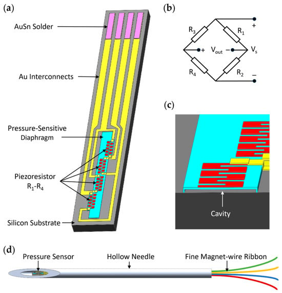
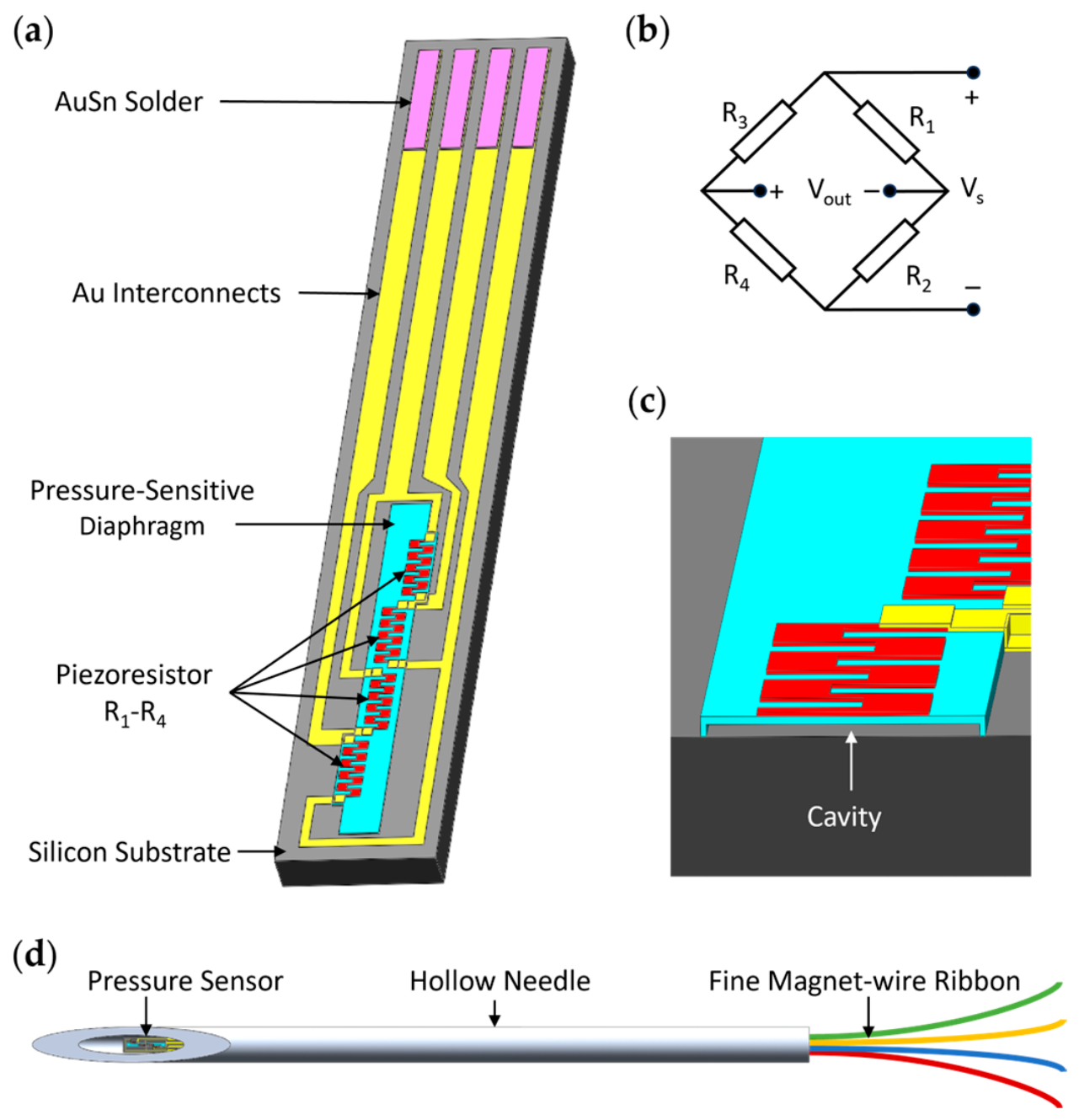
Figure 1 illustrates the proposed ultraminiature pressure sensor and its integration at the needle tip. The sensor chip measures 1250 μm long, 200 μm wide, and 50 μm thick (Figure 1a). It consists of a silicon substrate, a low-stress polysilicon pressure-sensitive diaphragm, four polysilicon piezoresistors, Au interconnects, and AuSn solder pads. The four serpentine piezoresistors, denoted as R1–R4, form a Wheatstone bridge (Figure 1b). A 1.5-μm-high sealed cavity beneath the 1-μm-thick diaphragm provides a reference pressure and space for diaphragm deflection (Figure 1c). A pressure difference across the diaphragm causes it to deform, changing the piezoresistor resistance and producing a differential voltage output from the bridge.
Figure 1.
Sensor structure and needle-tip integration: (a) overall structure of the sensor chip; (b) Wheatstone bridge configuration of the four piezoresistors; (c) enlarged cutaway view of the pressure-sensitive diaphragm and underlying cavity; (d) schematic of sensor integration at acupuncture needle tip, with electrical connections routed through the needle lumen using a fine magnet-wire ribbon.
The ultraminiature pressure sensor can be mounted in the tip of a hollow needle with an outer diameter of 450 μm and an inner diameter of 230 μm (Figure 1d). A fine magnet-wire ribbon connects the AuSn solder pads to an external flexible printed circuit through the needle lumen. Replacing the long SU-8-supported thin-film interconnects of the previous design [10] with this wire ribbon reduces the wafer area required per device. Parylene C exhibits biocompatibility, electrical insulation, mechanical flexibility, and the ability to form conformal coatings via chemical vapor deposition [16]. The diaphragm surface was therefore coated with Parylene C to provide electrical insulation during measurements in muscle.
2.2. Sensor Modeling
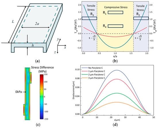
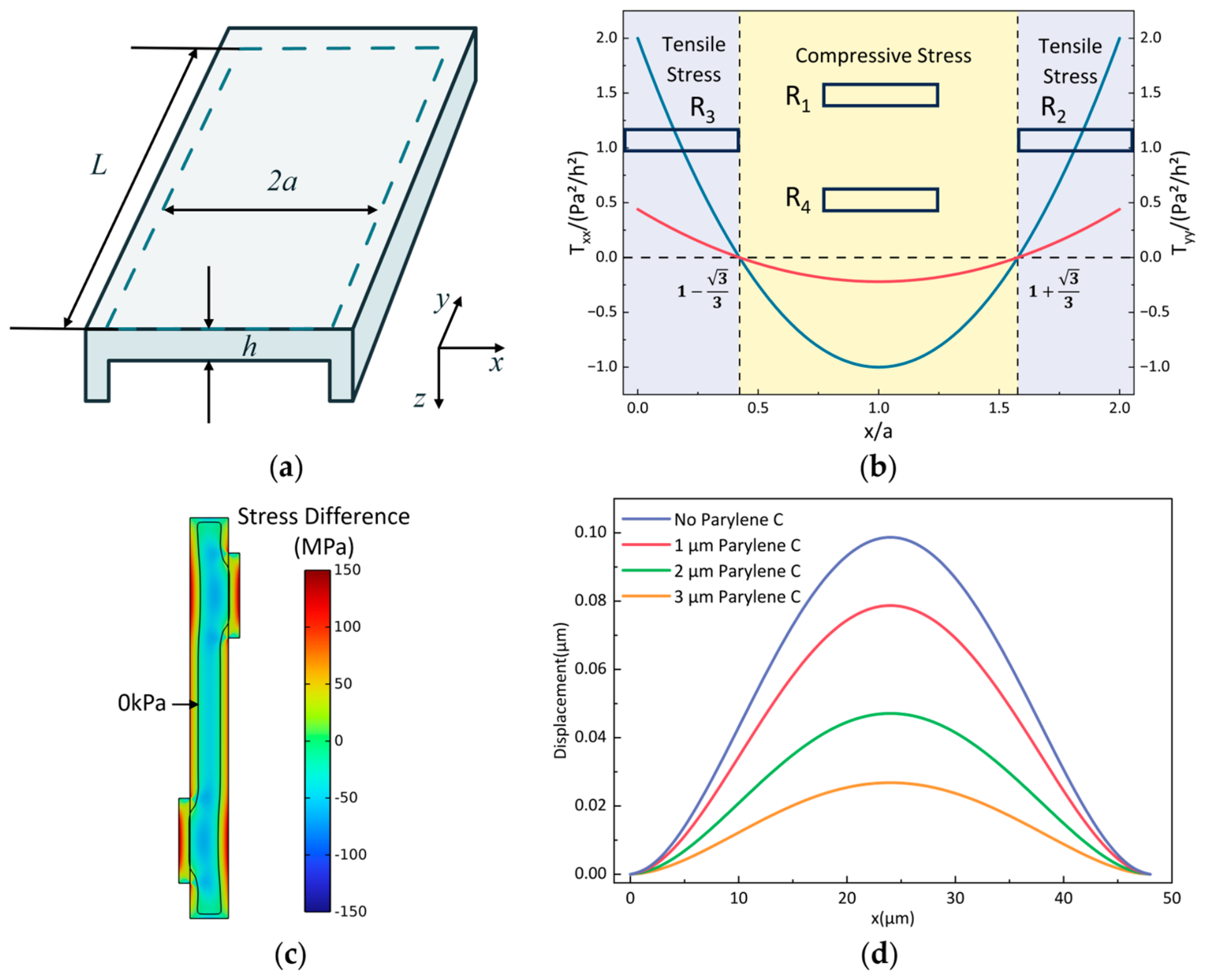
To guide the placement of the piezoresistors, the elongated diaphragm was approximated as a clamped rectangular plate. As illustrated in Figure 2a, the diaphragm has a length of L = 500 μm, a width of 2a = 48 μm, and a thickness of h = 1 μm. Because L ≫ 2a, a one-dimensional plate model was adopted away from the short edges. Under small-deflection isotropic elasticity and negligible initial membrane stress, the longitudinal and transverse surface stresses generated by a uniform pressure difference p were calculated using Equations (1) and (2) [17].
here, ν is the Poisson’s ratio of the diaphragm material, and x ranges from 0 to 2a. As shown in Figure 2b, the calculated stress distribution contains tensile regions near the long edges and a compressive region near the diaphragm center, with stress reversal at . Accordingly, R1 and R4 were placed in the central compressive regions, whereas R2 and R3 were positioned in the tensile regions. The tensile edge regions were locally widened to accommodate the serpentine resistors. A three-dimensional COMSOL model further verified the stress distribution in the modified diaphragm geometry, as shown in Figure 2c. The model included a 1-μm-thick polysilicon sensing diaphragm, using the built-in polysilicon material with a Young’s modulus of 160 GPa and a Poisson’s ratio of 0.22. Fixed constraints were applied to all lateral surfaces of the diaphragm, and a boundary load of 100 kPa was applied to its upper surface.
Tyy(x) = νTxx(x)
Figure 2.
Analytical modeling and finite element analysis of the pressure-sensitive diaphragm: (a) diaphragm geometry and coordinate system; (b) analytically calculated normalized surface stress distributions and schematic piezoresistor positions; (c) finite element distribution of the in-plane stress difference, Txx − Tyy, in the diaphragm with locally widened regions; (d) displacement profiles across the diaphragm width under a pressure of 100 kPa for Parylene C coating thicknesses of 0, 1, 2, and 3 μm.
Four piezoresistors form the Wheatstone bridge shown in Figure 1b. Assuming equal initial resistances and small pressure-induced resistance changes, with ΔR1 = ΔR4 and ΔR2 = ΔR3, the bridge output can be approximated as:
Here, Vs is the supply voltage. Because the resistor pairs undergo opposite stress states, their resistance changes contribute constructively to the differential output, thereby converting diaphragm deformation into a measurable voltage signal.
To investigate the effect of the Parylene C coating on the sensitivity of the pressure sensor, we added a Parylene C layer to the diaphragm model in Figure 2c and compared the diaphragm displacements under a uniform pressure difference of 100 kPa. The built-in Parylene C material in COMSOL 6.3 was used, with a Young’s modulus of 2.758 GPa and a Poisson’s ratio of 0.4. As shown in Figure 2d, the diaphragm displacement decreases with increasing Parylene C coating thickness under the same applied pressure, indicating that the coating suppresses pressure-induced deformation of the diaphragm. According to the structural configuration of the designed sensor, the strain at the piezoresistors on the diaphragm is also expected to decrease, resulting in smaller resistance changes and a lower bridge output, thereby lowering the pressure sensitivity. Parylene C films thicker than 1 μm have been reported to provide pinhole-free electrical insulation [18], although coating quality depends on the sample surface condition and deposition conditions. Based on this report and our experience with the deposition system, a thickness of 1.3 μm was selected as a practical compromise between electrical insulation and sensitivity retention. The effect of the coating on pressure sensitivity was evaluated experimentally.
3. Fabrication and Packaging
3.1. Fabrication Process
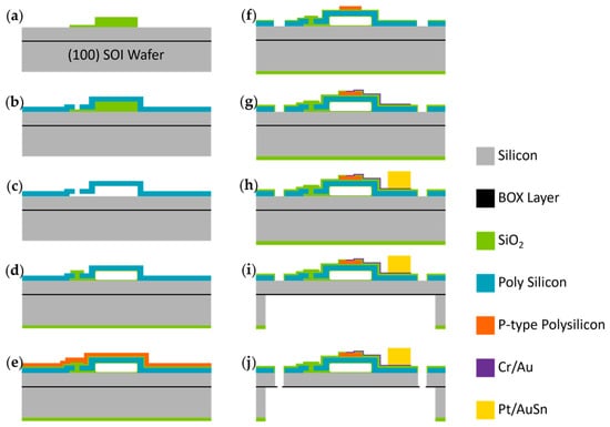
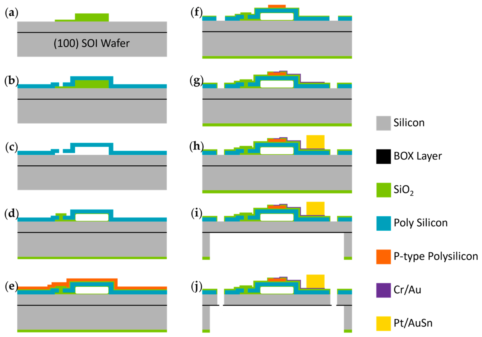
The ultraminiature pressure sensor was designed to be 50 μm thick to fit within the 230-μm inner diameter of the hollow needle. Therefore, we fabricated it from a 4-inch SOI wafer comprising a 50-μm-thick device layer, a 2-μm-thick buried oxide (BOX) layer, and a 400-μm-thick handle layer. During device release, the BOX layer acts as an etch stop. Figure 3 illustrates the fabrication process described below.
Figure 3.
Fabrication process of the ultraminiature pressure sensor: deposition and patterning of the sacrificial layers for the (a) cavity and etching channels; (b) deposition of the diaphragm layer and etching of the etch access holes; (c) wet etching of the sacrificial layers; (d) sealing of the pressure-sensing cavity; (e) polysilicon deposition and boron ion implantation; (f) patterning of the piezoresistors and front-side release trenches; (g) fabrication of Cr/Au interconnects; (h) deposition of Pt/Au–Sn solder layers; (i) backside deep etching; (j) front-side etching and device release.
(a–d) The pressure-sensing cavity is fabricated using sacrificial SiO2 layers. Tetraethyl orthosilicate (TEOS) SiO2 layers with thicknesses of 1.5 and 0.2 μm are deposited by low-pressure chemical vapor deposition (LPCVD) and patterned to define the cavity and etchant access channels, respectively. A 1-μm-thick low-stress polysilicon diaphragm is then deposited and patterned to open etch access holes. The sacrificial SiO2 is removed in 40% hydrofluoric acid, and the cavity is sealed by LPCVD of a 1.5-μm-thick TEOS SiO2 layer, yielding a reference pressure of approximately 30 Pa. The SiO2 outside the sealed cavity is subsequently removed.
(e,f) The piezoresistors are fabricated by depositing a 0.2-μm-thick TEOS SiO2 insulation layer and a 0.5-μm-thick polysilicon layer, followed by boron implantation at a dose of 3.4 × 1014 cm−2 and an energy of 40 keV. A heavier boron implant of 5.5 × 1015 cm−2 is applied to the ohmic-contact regions. The piezoresistors and front-side release trenches are then defined by reactive ion etching (RIE).
(g,h) A 0.2-μm-thick TEOS SiO2 insulation layer is deposited and patterned to open contact holes. Cr/Au interconnects are formed by magnetron sputtering and lift-off, followed by evaporation and lift-off of a 0.2-μm-thick Pt diffusion barrier and a 4-μm-thick AuSn solder layer. Eutectic AuSn is selected for subsequent thermocompression soldering because of its compatibility with Au-metalized surfaces, mechanical strength, and thermal stability [19,20,21].
(i,j) The sensor chips are released by backside deep RIE of the 400-μm-thick handle layer, followed by front-side etching through the 50-μm-thick device layer along the predefined release trenches. Final separation is achieved by fracture of the remaining BOX layer along the device boundaries.
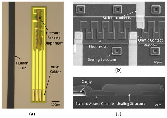
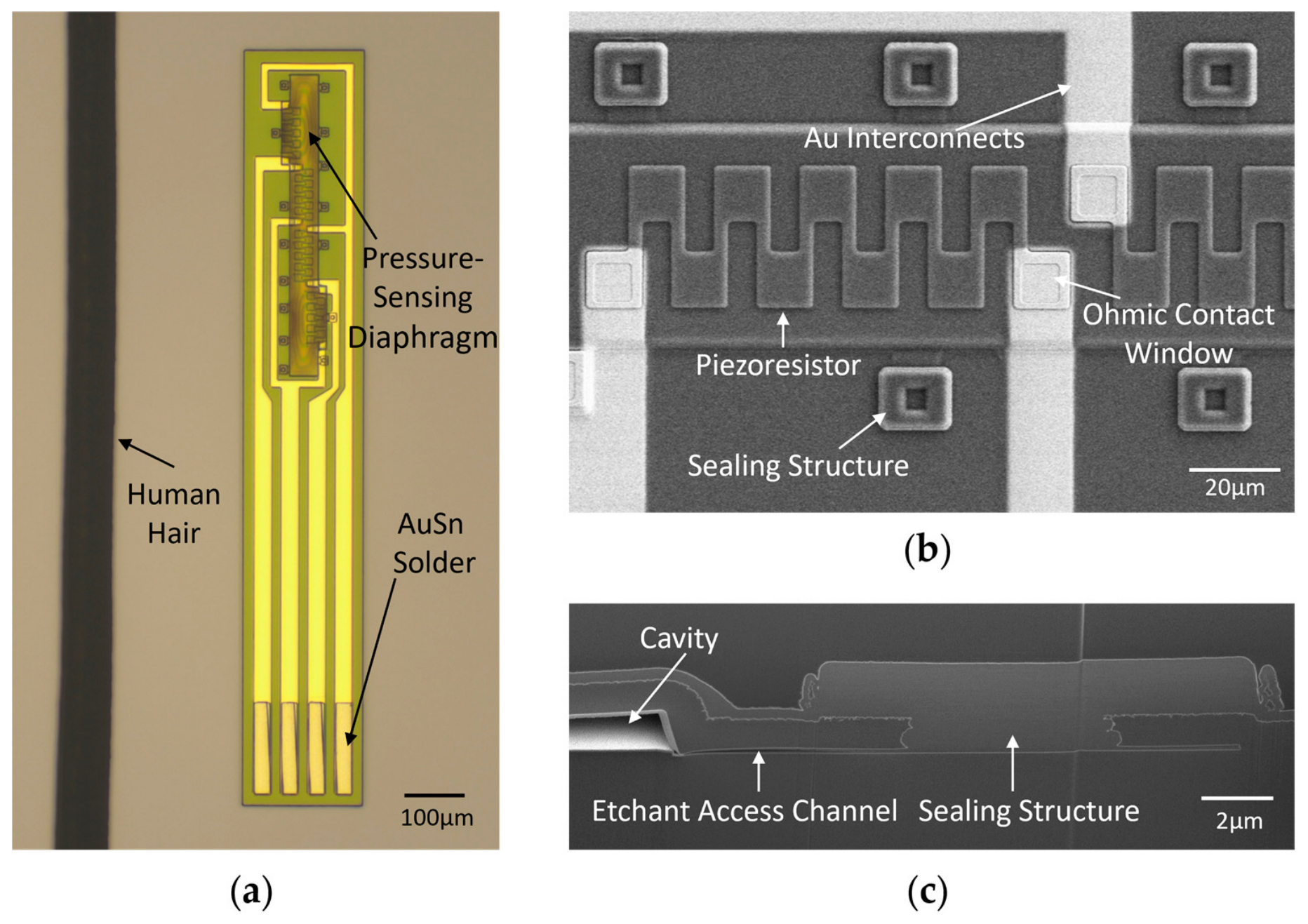
Figure 4 presents optical and scanning electron microscopy (SEM) images of the fabricated sensor. The optical image in Figure 4a shows the elongated chip, with the pressure-sensing region at one end and four Au interconnects leading to the Au–Sn solder pads at the opposite end. A human hair is included for scale. Figure 4b provides a magnified view of the diaphragm, showing the serpentine polysilicon piezoresistor and its connections to the Au interconnects through the ohmic-contact windows. The structures sealing the sacrificial-layer release openings are also visible. The cross-sectional SEM image in Figure 4c reveals the cavity beneath the diaphragm and the sealing structure over the etchant-access channel.
Figure 4.
Micrographs of the fabricated pressure sensor: (a) optical micrograph of the sensor chip alongside a human hair for size comparison; (b) SEM image showing a serpentine polysilicon piezoresistor, Au interconnects, ohmic contact windows, and sealing structures; (c) cross-sectional SEM image showing the vacuum cavity, etchant access channel, and sealing structure.
3.2. Sensor Packaging and Needle-Tip Integration
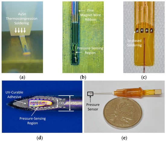
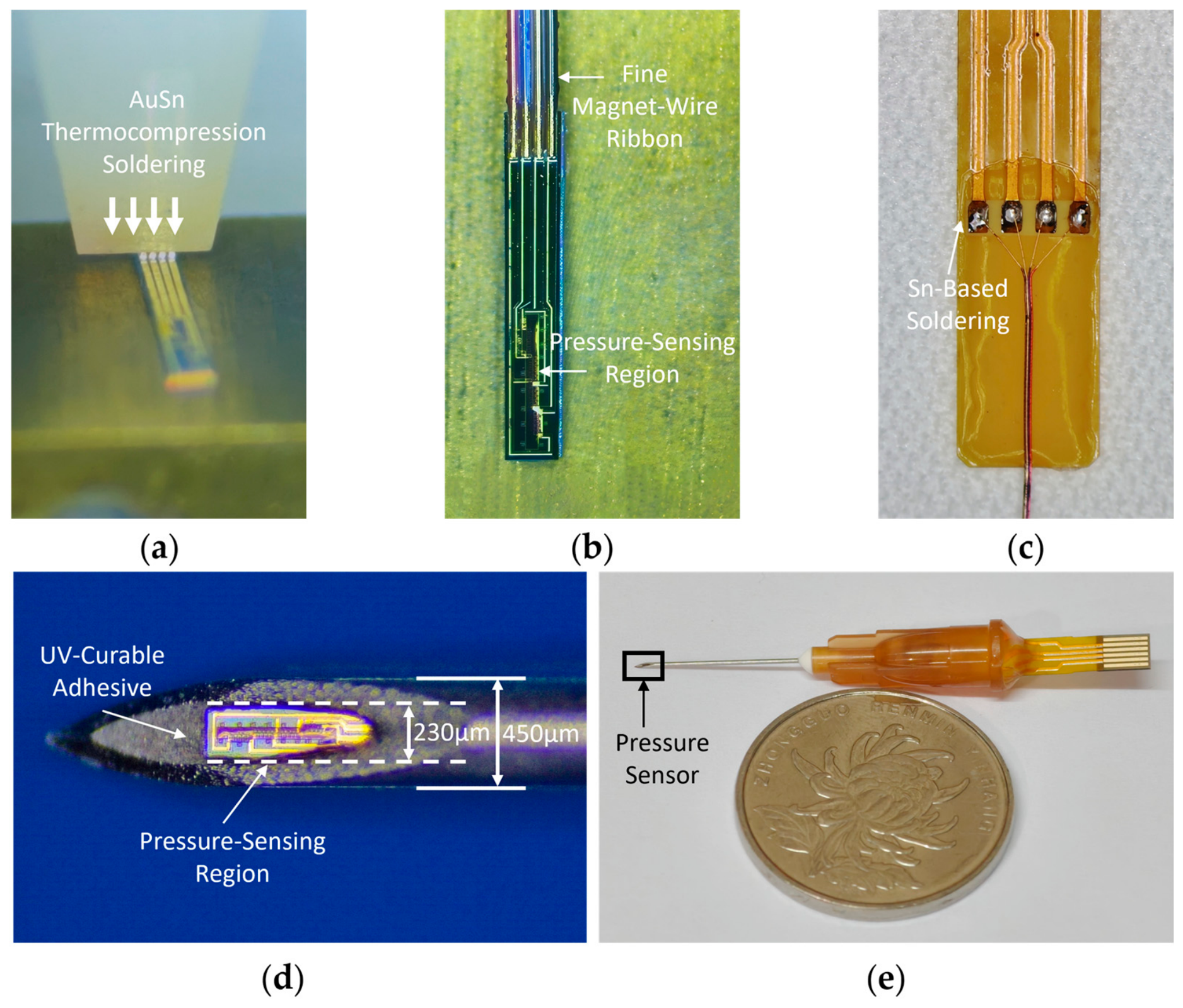
The packaging and needle-tip integration scheme is illustrated in Figure 5. A customized ultrafine magnet-wire ribbon with gold-plated conductors is prepared with a pad pitch matching that of the AuSn pads on the sensor chip. In total, 0.2 mm of the insulation at the ribbon ends is removed by laser, exposing the underlying gold-plated conductors. The sensor chip is then placed on the stage of a semiautomatic thermocompression soldering machine, and the exposed wire ends are aligned with the AuSn pads. As shown in Figure 5a, AuSn thermocompression soldering is performed at a bonding force of 40–45 gf and a temperature of 300 ± 10 °C, with a dwell time of 3 s. The sensor chip connected to the ultrafine wire ribbon is shown in Figure 5b.
Figure 5.
Sensor packaging and needle-tip integration: (a) AuSn thermocompression soldering of the fine magnet-wire ribbon to the sensor pads; (b) the sensor connected to the wire ribbon after AuSn soldering; (c) Sn-based soldering of the wire ribbon to an external FPC; (d) magnified view of the sensor secured at the tip of a hollow needle using UV-curable adhesive; (e) the assembled sensing needle, with a coin for size comparison.
After soldering, the chip–wire assembly is treated with oxygen plasma and subsequently coated with a 1.3-μm-thick Parylene C layer by vapor deposition to provide electrical insulation for the sensor and exposed interconnects. The free end of the wire ribbon is threaded through the needle lumen from the needle tip and exits at the needle hub. The ribbon is connected to an external FPC by Sn-based soldering, as shown in Figure 5c.
LOCTITE® AA 3311™ (Henkel AG & Co. KGaA, Düsseldorf, Germany), a UV-curable adhesive, has been undergone biocompatibility testing under the manufacturer’s test protocols and is suitable for bonding gaps smaller than 250 μm [22]. As shown in Figure 5d, the ultraminiature sensor was secured with this adhesive at the tip of a needle with an inner diameter of only 230 μm, while leaving the pressure-sensing region exposed through the needle-tip opening. The fully assembled sensing needle is shown in Figure 5e.
4. Test
4.1. Performance Test
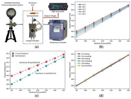
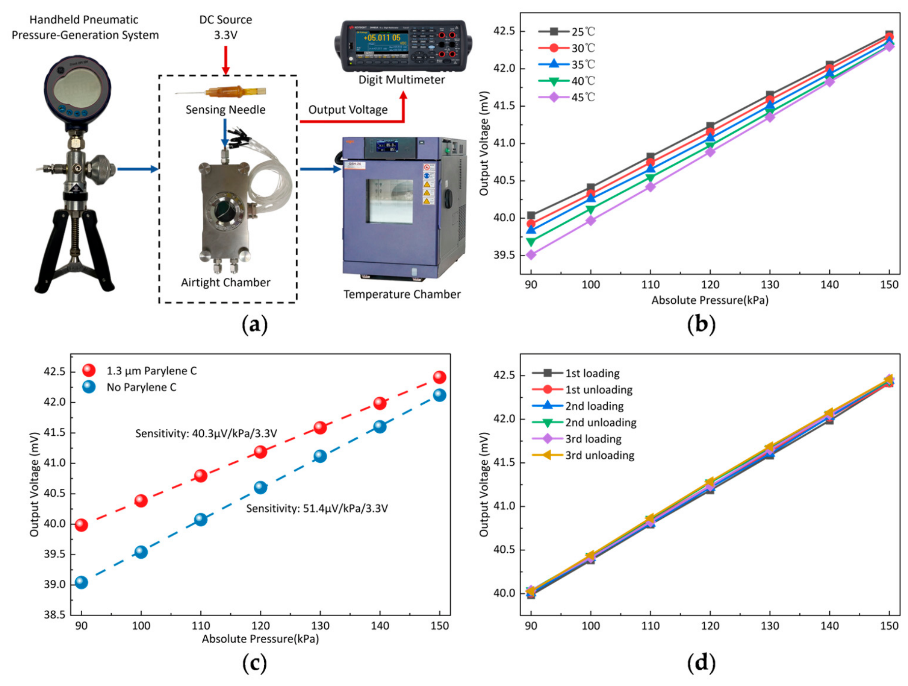
Figure 6a illustrates the experimental setup used to characterize the pressure sensor. The assembled sensing needle was placed inside a custom airtight chamber, which was connected to a pneumatic pressure-generation system consisting of a hand-operated pressure pump (PV211, Druck Inc., Leicester, UK) and a reference digital pressure gauge (DPI 104, Druck Inc., Leicester, UK) with an accuracy of ±0.05% FS. For temperature-dependent measurements, the entire airtight chamber was placed inside a benchtop temperature chamber (GSH-26, ESPEC Co., Ltd., Osaka, Japan). A DC excitation voltage of 3.3 V was applied to the sensor. The sensor output voltage was directly measured using a digital multimeter (34465A, Keysight Technologies, Inc., Santa Rosa, CA, USA).
Figure 6.
Pressure-characterization experimental setup and results: (a) schematic of the experimental setup; (b) pressure responses of the sensor at different temperatures ranging from 25 to 45 °C; (c) pressure responses before and after deposition of a 1.3-μm-thick Parylene C coating; (d) output voltage during three consecutive pressure loading–unloading cycles after coating.
Because the sensor is intended for in vivo acupuncture measurements, we characterized its pressure response over a temperature range of 25–45 °C to evaluate the effect of temperature variation under the intended operating conditions. The calibration range was set to an absolute pressure range of 90–150 kPa. This range was selected to cover pressures around the local atmospheric pressure and the pressure increases expected during in vivo needle insertion and manipulation. As shown in Figure 6b, the pressure sensitivity increased with temperature, corresponding to a temperature coefficient of sensitivity (TCS) of approximately +0.657%/°C over the 25–45 °C range. At 90 kPa, the output voltage decreased with increasing temperature, yielding a temperature coefficient of offset (TCO) of approximately −1.062% FS/°C. The nonlinearity of the output voltage–pressure relationship remained below 0.73% FS at all tested temperatures.
The effect of the 1.3-μm-thick Parylene C coating on sensor sensitivity was evaluated by comparing the pressure responses before and after coating. As shown in Figure 6c, the sensitivity decreased from 51.4 to 40.3 μV/kPa at a 3.3 V excitation after coating, consistent with the simulated reduction in diaphragm displacement. As shown in Figure 6d, the coated sensor was further tested over three consecutive pressure loading–unloading cycles. The maximum hysteresis across the three cycles was 2.52% FS, calculated as the largest absolute difference between the loading and unloading outputs at the same pressure, normalized by the full-scale output span.
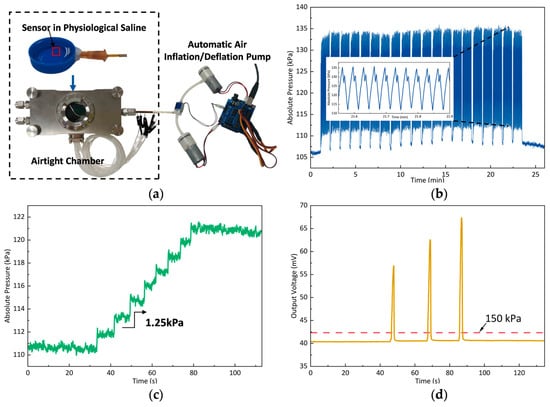
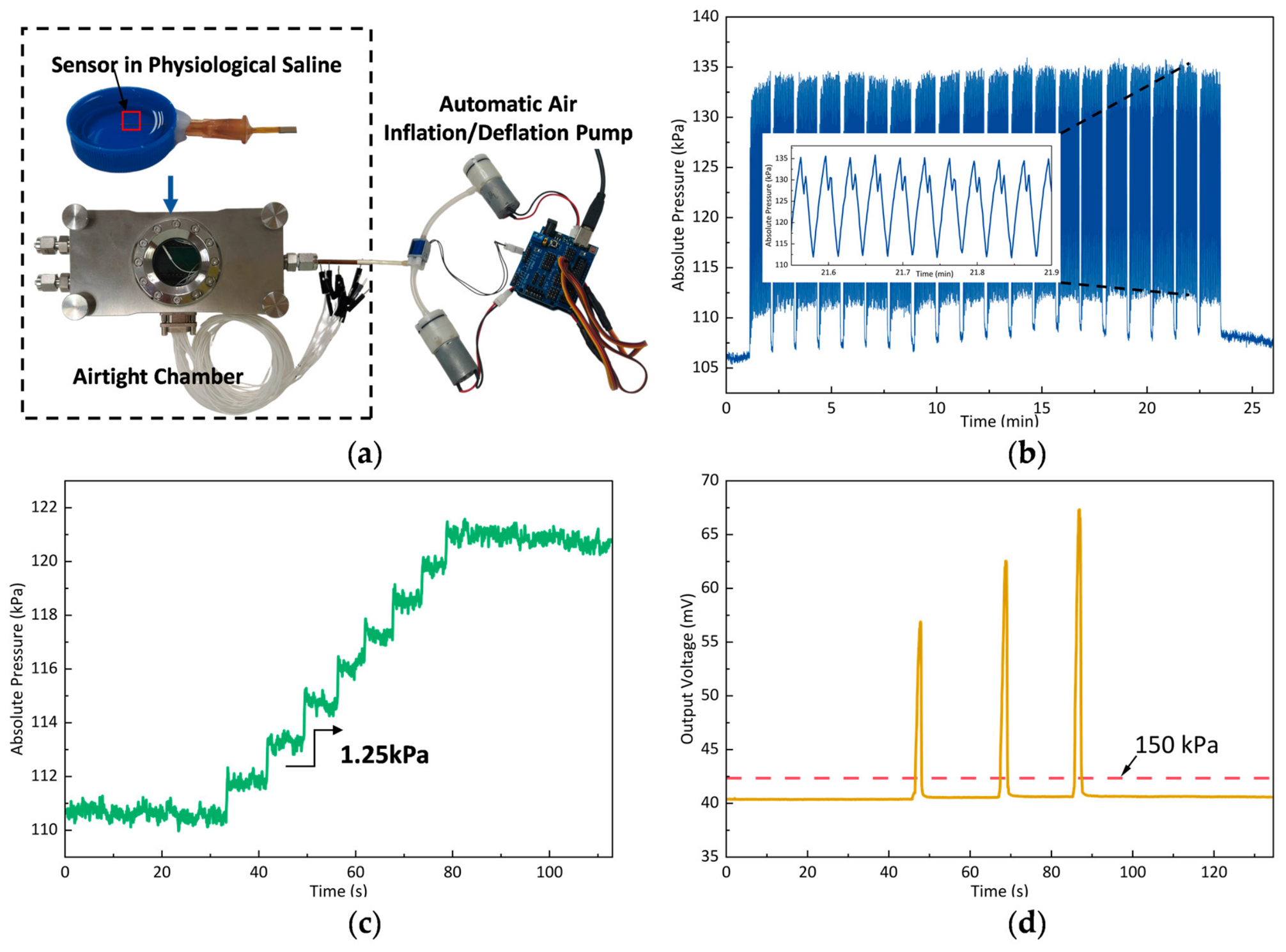
Additional tests evaluated the sensor’s cyclic stability, pressure resolution, and overload tolerance (Figure 7). The sensor exhibited repeatable responses over 600 pressure loading–unloading cycles while immersed in physiological saline. The pressure resolution estimated using the 3σ criterion was 0.72 kPa, and a 1.25 kPa pressure variation was experimentally resolved. Following successive overloads, with the final pressure exceeding 700 kPa absolute, the output returned close to its initial baseline after unloading.
Figure 7.
Additional characterization of the needle-integrated pressure sensor: (a) experimental setup for pressure cycling in physiological saline; (b) sensor response over 600 loading–unloading cycles, with an enlarged segment shown in the inset; (c) response to small pressure variation; and (d) response to successive overloads.
Table 1 compares the present sensor with previously reported needle-related miniaturized pressure sensors. In this work, an ultraminiature pressure sensor is directly integrated at the tip of a 450-μm-diameter acupuncture needle without requiring a liquid-mediated pressure transmission structure. It retains an effective pressure response after Parylene C insulation coating, enabling monitoring of local muscle mechanical responses during acupuncture manipulation.
Table 1.
Comparison of the present sensor with previously reported needle-related miniaturized pressure sensors.
4.2. In Vivo Measurement in Rats
Thrusting–lifting is a basic needle manipulation technique in traditional Chinese acupuncture. The assembled sensing needle was evaluated during acupuncture at the Zusanli (ST36) acupoint in Sprague–Dawley rats, with 60 s of thrusting–lifting manipulation. The Zusanli (ST36) acupoint was located approximately 5 mm distal to the fibular head and 2 mm lateral to the anterior tibial tuberosity [23]. All rats used for the experiments were purchased from Chengdu Dashuo Experimental Animal Co., Ltd. (Chengdu, China) and housed in the Animal Experimental Center of the Chengdu University of Traditional Chinese Medicine. All animal-related experiments were approved by the Animal Ethics Committee of Chengdu University of TCM (receipt number: 2024543; approval date: 25 November 2024).
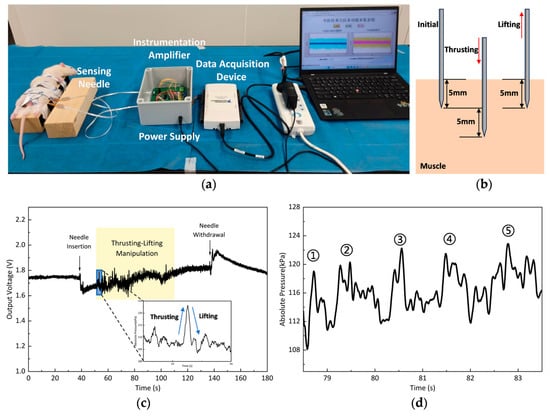
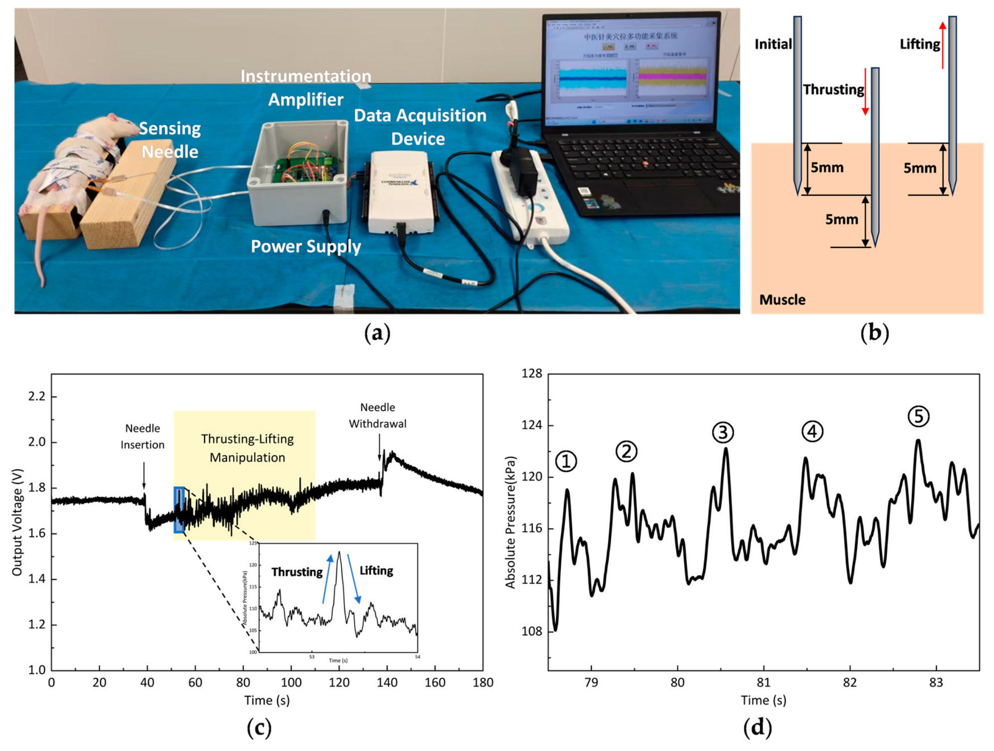
As shown in Figure 8a, a portable measurement system was developed for in vivo acupuncture experiments. A precision power supply module provided a 3.3 V excitation voltage to the pressure sensor. An instrumentation amplifier amplified the differential sensor output, with a DC offset applied to match the input range of the data acquisition device, NI USB-6218 (National Instruments Corporation, Austin, TX, USA). The signals were acquired at a sampling rate of 10 kHz and transferred to a laptop computer for real-time display and recording. The acquired signals were smoothed using a Savitzky–Golay filter with a second-order polynomial and a 1000-point window (corresponding to 100 ms at a sampling rate of 10 kHz) to suppress noise.
Figure 8.
In vivo pressure measurements during acupuncture at the Zusanli (ST36) acupoint in rats: (a) photograph of the experimental setup; (b) schematic illustration of needle thrusting and lifting within muscle; (c) sensor output voltage during needle insertion, thrusting–lifting manipulation, and withdrawal, with an inset showing the converted pressure response during the first thrusting–lifting cycle; (d) a representative 5-s segment of the converted pressure signal during subsequent thrusting–lifting manipulation, with five successive peaks labeled ①–⑤.
Before the in vivo measurements, preliminary checks showed stable sensor output during immersion of the needle tip in physiological saline and during up-and-down needle movement in air. These observations supported electrical insulation in a wet environment and indicated no noticeable baseline drift caused by needle and wire movement alone under the tested conditions. The rats remained awake throughout the experiments, and the room temperature was maintained at 23 ± 1 °C. Before pressure measurement, a temperature-sensing needle developed in our previous work [6] was inserted approximately 1 cm from the acupoint to monitor the local muscle temperature. The pressure-sensing needle was inserted after the temperature reading had stabilized. After insertion to an initial depth of 5 mm, the needle was repeatedly moved downward by 5 mm (thrusting) and then upward by 5 mm to return to the initial depth (lifting). The directions of needle movement are illustrated in Figure 8b. The sensor output and animal responses were monitored throughout the manipulation. During the in vivo experiments, the sensor was in direct contact with muscle tissue and detected the local mechanical loading transmitted to the sensing diaphragm. Given the small dimensions of the diaphragm, variations in normal loading across its surface were assumed to be negligible, allowing the load to be approximated as uniformly distributed. The recorded output voltage was therefore converted into an equivalent local pressure using the calibration relationship obtained under uniform air pressure in the airtight chamber. This equivalent pressure was used to characterize the local mechanical response of muscle tissue.
As shown in Figure 8c, needle insertion and withdrawal were accompanied by distinct changes in the sensor output. During thrusting–lifting manipulation, the signal exhibited repeated rises and falls superimposed on a gradually increasing baseline. Pronounced animal movements were observed at the beginning of manipulation, coinciding with larger signal fluctuations. During the experiment, the temperature-sensing needle indicated that the local muscle temperature near the acupoint remained stable at 35.3 ± 0.2 °C. The recorded voltage was converted to pressure using a calibration curve adjusted to 35.3 °C on the basis of the TCS and TCO values, after accounting for the gain and DC offset of the signal-conditioning circuit. The inset in Figure 8c shows the pressure response during the first thrusting–lifting cycle. The pressure increased by more than 15 kPa and then decreased, with the pressure rise and fall qualitatively consistent with needle thrusting and lifting, respectively. Figure 8d shows a representative 5-s segment of the converted pressure signal during subsequent thrusting–lifting manipulation. Repeated pressure fluctuations were observed, with five successive peaks labeled ①–⑤. The sensor remained operational throughout needle insertion, thrusting–lifting manipulation, and withdrawal, supporting its feasibility for monitoring local muscle pressure responses during in vivo acupuncture.
5. Conclusions
We fabricated an ultraminiature pressure sensor integrated into the tip of a 450-μm-diameter acupuncture needle. AuSn soldering to an ultrafine wire ribbon enabled electrical connections through the 230-μm-diameter needle lumen. With a 1.3-μm-thick electrically insulating Parylene C coating, the sensor achieved a sensitivity of 40.3 μV/kPa at a 3.3 V excitation and a maximum hysteresis of 2.52% FS. In vivo experiments at the Zusanli (ST36) acupoint in rats demonstrated continuous sensor operation throughout needle insertion, thrusting–lifting manipulation, and withdrawal. This work provides a tool for quantitatively investigating local muscle response during acupuncture, with the potential to support more precise needle manipulation.
Author Contributions
C.S. and Z.Y. contributed to the investigation, design, simulation, and fabrication of the proposed device; X.C. and X.L. (Xiaojing Liu) contributed to the device testing; W.L. and Z.N. contributed to the device packaging; S.Y. and X.L. (Xinxin Li) contributed to the research idea and project supervision. All authors have read and agreed to the published version of the manuscript.
Funding
This research was funded by the National Natural Science Foundation of China, grant number 62227815.
Institutional Review Board Statement
The animal study protocol was approved by the Animal Ethics Committee of Chengdu University of TCM (receipt number: 2024543; approval date: 25 November 2024).
Informed Consent Statement
Not applicable.
Data Availability Statement
The original contributions presented in this study are included in this article; further inquiries can be directed to the corresponding author.
Acknowledgments
The authors thank the Innovation Team and Talents Cultivation Program of National Administration of Traditional Chinese Medicine for supporting the development of this project.
Conflicts of Interest
Wei Li. serves as General Manager and Zao Ni serves as Deputy General Manager at Shanghai MISTechnology Co., Ltd. Both authors provided technical support for the AuSn soldering process used in device packaging. The remaining authors declare no conflicts of interest.
Abbreviations
The following abbreviations are used in this manuscript:
| FS | Full scale |
| TCM | Traditional Chinese medicine |
| FPC | Flexible printed circuit |
| BOX | Buried oxide |
| TEOS | Tetraethyl orthosilicate |
| LPCVD | Low-pressure chemical vapor deposition |
| BOE | Buffered oxide etchant |
| RIE | Reactive ion etching |
| SEM | Scanning electron microscopy |
| TCS | Temperature coefficient of sensitivity |
| TCO | Temperature coefficient of offset |
References
- Liu, S.; Wang, Z.; Su, Y.; Qi, L.; Yang, W.; Fu, M.; Jing, X.; Wang, Y.; Ma, Q. A Neuroanatomical Basis for Electroacupuncture to Drive the Vagal–Adrenal Axis. Nature 2021, 598, 641–645, Erratum in Nature 2022, 601, E9. https://doi.org/10.1038/s41586-021-04001-4. [Google Scholar] [CrossRef] [Scilit] [PubMed]
- Wang, B.-G.; Xu, L.-L.; Yang, H.-Y.; Xie, J.; Xu, G.; Tang, W.-C. Manual Acupuncture for Neuromusculoskeletal Disorders: The Selection of Stimulation Parameters and Corresponding Effects. Front. Neurosci. 2023, 17, 1096339. [Google Scholar] [CrossRef] [Scilit] [PubMed]
- Chang, H.; Huo, M.; Zhang, Q.; Zhou, M.; Zhang, Y.; Si, Y.; Zhang, D.; Guo, Y.; Fang, Y. Flexible Needle-Type Microbiosensor for Real-Time Monitoring Traditional Acupuncture-Mediated Adenosine Release In Vivo. Biosens. Bioelectron. 2023, 235, 115383. [Google Scholar] [CrossRef] [Scilit] [PubMed]
- Li, Y.-C.; Yu, Y.; Qiao, X.; Ren, L.-J.; Xu, J.-W.; Wang, X.; Gu, W.; Yao, W. A Robot Arm-Assisted Acupuncture System with Motion and Force Monitoring: Establishment and Validation. Front. Bioeng. Biotechnol. 2025, 13, 1563263. [Google Scholar] [CrossRef] [Scilit] [PubMed]
- Liu, L.; Hu, X.; Su, Y.; Lin, C.; Wang, Y. Application and Development of Nanotechnology in Traditional Chinese Acupuncture in Recent 20 Years: A Comprehensive Review. ACS Appl. Mater. Interfaces 2025, 17, 22161–22183. [Google Scholar] [CrossRef] [Scilit] [PubMed]
- Song, C.; Yu, Z.; Feng, W.; Sun, K.; Wen, C.; Zhang, S.; Yu, S.; Li, X. A Flexible Temperature Sensor Integrated at Needle Tip for In Situ Acupoint Temperature Monitoring. Micromachines 2024, 15, 924. [Google Scholar] [CrossRef] [Scilit] [PubMed]
- Ming, T.; Lan, T.; Yu, M.; Wang, H.; Deng, J.; Kong, D.; Yang, S.; Shen, Z. Platinum Black/Gold Nanoparticles/Polyaniline Modified Electrochemical Microneedle Sensors for Continuous In Vivo Monitoring of pH Value. Polymers 2023, 15, 2796. [Google Scholar] [CrossRef] [Scilit] [PubMed]
- Liu, W.; Li, Q.; Han, Q. Needle-in-Needle Electrochemical Sensor for in-Vivo Monitoring of Anticancer Drug Etoposide. Biosens. Bioelectron. 2024, 258, 116348. [Google Scholar] [CrossRef] [Scilit] [PubMed]
- Yang, X.; Yin, Z.-Z.; Zheng, G.; Zhou, M.; Zhang, H.; Li, J.; Cai, W.; Kong, Y. Molecularly Imprinted Miniature Electrochemical Biosensor for SARS-CoV-2 Spike Protein Based on Au Nanoparticles and Reduced Graphene Oxide Modified Acupuncture Needle. Bioelectrochemistry 2023, 151, 108375. [Google Scholar] [CrossRef] [Scilit] [PubMed]
- Zhan, S.; Zhang, J.; Gao, C.; Yin, Z.; Liu, H. An Electrochemical Microbiosensor for Serotonin Based on Surface Imprinted Layer Coordinated Bimetal Functionalized Acupuncture Needle. Talanta 2024, 277, 126334. [Google Scholar] [CrossRef] [Scilit] [PubMed]
- Xu, J.; Song, A.; Chen, Y. Acupuncture Manipulation Measurement and Identification Based on Miniature Multiaxis Force/Torque Sensor. IEEE Sens. J. 2024, 24, 33806–33815. [Google Scholar] [CrossRef] [Scilit]
- Kishimoto, T.; Agetsuma, M.; Hoshino, A.; Takahashi, H. Needle-Type Pressure Sensor with Silicone Oil and Parylene Membrane inside for Minimally Invasive Measurement. Electron. Commun. Jpn. 2023, 106, e12420. [Google Scholar] [CrossRef] [Scilit]
- Roh, J.-H.; Shin, K.-S.; Song, T.-H.; Kim, J.; Lee, D.-S. Development of an Implantable Capacitive Pressure Sensor for Biomedical Applications. Micromachines 2023, 14, 975. [Google Scholar] [CrossRef] [Scilit] [PubMed]
- Ben-Avraham, B.; Jacobson, E.; Richter, Y.; Witberg, G.; Burkhoff, D.; Uriel, N.; Ben-Gal, T.; Sharoni, E. First In-Human Study of a Novel Left Atrial Pressure Sensor: The Microtech LVAD Study. J. Card. Fail. 2025, 31, 1763–1766. [Google Scholar] [CrossRef] [Scilit] [PubMed]
- Tang, H.; Yang, Y.; Liu, Z.; Li, W.; Zhang, Y.; Huang, Y.; Kang, T.; Yu, Y.; Li, N.; Tian, Y.; et al. Injectable Ultrasonic Sensor for Wireless Monitoring of Intracranial Signals. Nature 2024, 630, 84–90. [Google Scholar] [CrossRef] [Scilit] [PubMed]
- Kohler, A.; Blendinger, F.; Müller, S.; Mescheder, U.; Bucher, V. Feasibility of Parylene C for Encapsulating Piezoelectric Actuators in Active Medical Implants. Front. Med. Technol. 2023, 5, 1211423. [Google Scholar] [CrossRef] [Scilit] [PubMed]
- Bao, M. Chapter 2—Mechanics of Beam and Diaphragm Structures. In Analysis and Design Principles of MEMS Devices; Elsevier Science: Amsterdam, The Netherlands, 2005; pp. 33–114. ISBN 978-0-444-51616-9. [Google Scholar]
- Trantidou, T.; Tariq, M.; Terracciano, C.M.; Toumazou, C.; Prodromakis, T. Parylene C-Based Flexible Electronics for pH Monitoring Applications. Sensors 2014, 14, 11629–11639. [Google Scholar] [CrossRef] [Scilit] [PubMed]
- Liu, C.; Liu, C. An Analytical Review on Interfacial Reactions in High-Temperature Die-Attach: The Insights into the Effect of Surface Metallization and Filler Materials. Manuf. Rev. 2025, 12, 1. [Google Scholar] [CrossRef] [Scilit] [PubMed]
- Chen, C.; Sun, M.; Cheng, Z.; Liang, Y. Microstructure Evolution and Shear Strength of the Cu/Au80Sn20/Cu Solder Joints with Multiple Reflow Temperatures. Materials 2022, 15, 780. [Google Scholar] [CrossRef] [Scilit] [PubMed]
- Schwan, H.; Mohan, N.; Schmid, M.; Saha, R.K.; Klassen, H.; Müller, K.; Elger, G. Sintering for High Power Optoelectronic Devices. Micromachines 2025, 16, 1164. [Google Scholar] [CrossRef] [Scilit] [PubMed]
- Henkel AG & Co. KGaA. LOCTITE® AA 3311TM Technical Data Sheet; Henkel Adhesive Technologies: Düsseldorf, Germany, 2026. [Google Scholar]
- Liu, J.-P.; Tu, L.-T.; Yang, K.-Z.; Li, Y.-Y.; Gong, Y.; Han, B.-X.; Liu, C.; Xia, T.-Q.; Liu, Y.; Hao, X.-M.; et al. Differential Effects of Electroacupuncture and Manual Acupuncture on Spontaneously Hypertensive Rats: Insights from Intestinal Microbiota and Metabolomics. Front. Mol. Biosci. 2025, 12, 1619356. [Google Scholar] [CrossRef] [Scilit] [PubMed]

Disclaimer/Publisher’s Note: The statements, opinions and data contained in all publications are solely those of the individual author(s) and contributor(s) and not of MDPI and/or the editor(s). MDPI and/or the editor(s) disclaim responsibility for any injury to people or property resulting from any ideas, methods, instructions or products referred to in the content. |
© 2026 by the authors. Licensee MDPI, Basel, Switzerland. This article is an open access article distributed under the terms and conditions of the Creative Commons Attribution (CC BY) license.