


Abstract
In order to simultaneously improve the imaging resolution and sensitivity of piezoelectric micromachined ultrasonic transducers (pMUTs), a pMUT with an I-shaped composite diaphragm was developed in this work. Compared with the conventional rectangular diaphragm structure, the I-shaped structure is formed by removing the piezoelectric layer along the edges of the two long sides while retaining the remaining portion. By this design, the residual stress of the piezoelectric film is effectively reduced, and both the sensitivity and the resonant frequency of the pMUT are improved. Moreover, unlike existing residual-stress-releasing structures such as hole- or groove-etched structures, where the diaphragm is no longer a continuous membrane and through-thickness holes or grooves are present, only the piezoelectric layer is etched in the proposed design. Consequently, no additional packaging requirements are imposed on the composite diaphragm, and the intricate sealing issue associated with through-hole structures is circumvented. A comprehensive comparison from multiple aspects was performed between ZnO-based and AlN-based pMUTs. It was shown by simulation results that the ZnO-based pMUT was superior to the AlN-based counterpart in terms of transmitting sensitivity, receiving sensitivity, and loop gain. On this basis, the ZnO-based pMUT with an I-shaped diaphragm was successfully fabricated and characterized. The performance of the PMUT was evaluated in electronic fluorinated fluid (FC-3283). The results show that the device exhibits a resonant frequency of 10 MHz, with a transmitting sensitivity level of 173.5 dB (re 1 μPa/V), a receiving sensitivity level of −242.1 dB (re 1 V/μPa), a loop gain of −68.6 dB, and a −6 dB bandwidth of 10.65%. These results indicate that high sensitivity was achieved at a high operating frequency, providing a technical reference for the design and application of high-frequency, high-sensitivity pMUT arrays, and demonstrating considerable potential for applications in underwater detection, ultrasonic imaging, and beyond.
1. Introduction
Ultrasonic waves, characterized by excellent directivity, strong penetrability, and ease of acoustic energy focusing, hold substantial application value in underwater detection, medical diagnostics, and industrial inspection. As the core enabling components of ultrasonic systems, transducers facilitate bidirectional electromechanical energy conversion and are extensively deployed across a broad spectrum of fields, including medical imaging and non-invasive therapy [1,2,3,4], industrial nondestructive testing [5,6,7], underwater detection [8,9], flow monitoring [10,11], automotive electronics [12,13], and smart home systems [14,15,16]. Driven by the escalating demand for high-resolution imaging and micro-/nano-scale detection, these transducers are progressively advancing toward higher operating frequencies, greater miniaturization, and improved sensitivity. Micromachined ultrasonic transducers (MUTs), realized through micro-electro-mechanical systems (MEMS) technology that leverages thin-film deposition and micro/nanofabrication processes, are capable of achieving elevated frequencies while offering distinct advantages in terms of compact form factor, high integration density, superior reliability, and low cost in mass production. Consequently, MUTs are poised to overcome the inherent performance bottlenecks of conventional transducers and meet the stringent requirements of portable array systems and high-precision imaging [17,18,19,20,21,22,23]. Based on their electromechanical transduction mechanisms, MEMS-based ultrasonic transducers are generally classified into two categories: capacitive (cMUT) and piezoelectric (pMUT). Compared with cMUTs, pMUTs eliminate the necessity for a DC bias, exhibit high electromechanical coupling coefficients, excellent compatibility with peripheral readout circuits, and minimal performance impact from parasitic capacitance. These inherent merits render pMUTs an increasingly prominent research focus within the field.
Imaging resolution and sensitivity are the core performance metrics of pMUTs. While a higher resonant frequency generally enables improved imaging resolution, an inherent trade-off exists between resonant frequency and sensitivity under a given device footprint, rendering simultaneous enhancement challenging. To improve pMUT performance, researchers have extensively explored various approaches, including modifying the diaphragm geometry, reducing its bending stiffness, and tailoring the electrode coverage area [24,25,26]. Based on conventional pMUT architectures, etching holes or grooves into the diaphragm has been employed to release residual stress and augment vibration amplitude, thereby improving either the resonant frequency or the sensitivity [27,28]. In 2019, Chen et al. fabricated V-shaped through-holes on a square diaphragm to relieve process-induced residual stress. Their simulation results indicated that the sound pressure level (SPL) of the device could be increased by 23 dB [28]. Nevertheless, such through-hole structures necessitate additional sealing processes when deployed in liquid-phase environments, which imposes considerable constraints on their practical engineering applications.
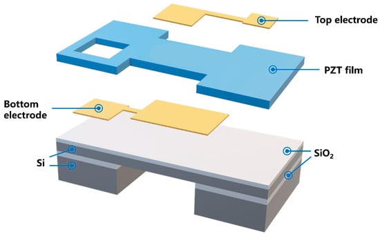
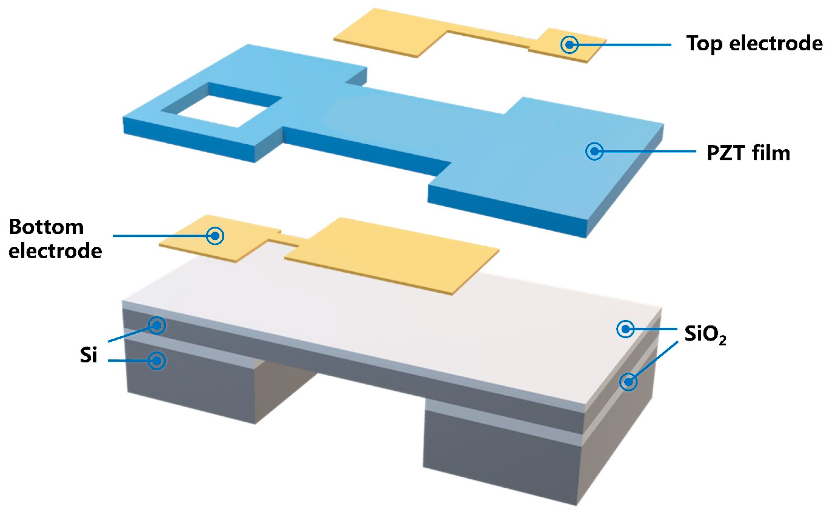
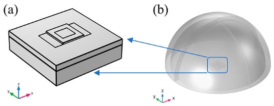
In view of the aforementioned challenges, we previously proposed a novel “I-shaped” diaphragm structure of pMUT, as illustrated in Figure 1 [29]. Compared with the conventional rectangular diaphragm structure, in the I-shaped structure, the piezoelectric layer along the edges of the two long sides is removed, while the remaining portion is retained. The patterning of the I-shaped structure enables residual stress to be effectively released during the fabrication process. The reduction in residual stress effectively increases the vibration amplitude of the diaphragm while maintaining high sensitivity. In addition, owing to the high bending stiffness of the I-shaped diaphragm, a relatively high resonant frequency is maintained. In addition, only the piezoelectric layer was etched, and no through-holes or grooves penetrating the diaphragm were formed. Therefore, no additional requirements were imposed on the packaging of the composite diaphragm, and the intricate sealing issue associated with through-hole structures was avoided. The effectiveness of the I-shaped architecture was experimentally verified through a fabricated pMUT based on a 4-μm-thick PZT piezoelectric layer, which exhibited a 15.28% improvement in resonant frequency and a 3 dB increase in loop gain over the conventional rectangular diaphragm design [29]. However, for PZT-based pMUTs, the loop gain reaches its maximum when the PZT thickness is 8 μm. Due to limitations in current process maturity, the fabrication and patterning of thick-film PZT remain challenging, making it difficult to approach the theoretically optimal performance. Therefore, to further improve the sensitivity of pMUTs, this paper systematically compares the device performance of pMUTs based on two other commonly used piezoelectric materials, namely ZnO and AlN. Simulation results demonstrate that ZnO-based pMUTs outperform their AlN-based counterparts in terms of key metrics such as transmitting sensitivity, receiving sensitivity, and loop gain. On this basis, this paper reports on the fabrication and characterization of the proposed ZnO-based pMUT with an I-shaped composite diaphragm. The fabricated device exhibits well-rounded overall performance, providing a technical reference for the design and application of high-frequency, high-sensitivity pMUTs, and demonstrating considerable potential for applications in underwater detection, ultrasonic imaging, and beyond.
Figure 1.
Schematic of the I-shaped composite diaphragm structure.
2. Structural Optimization of the I-Shaped Composite Diaphragm
To systematically compare the performance of the pMUTs with an I-shaped composite diaphragm using ZnO and AlN as the piezoelectric layer, this paper employs the Finite Element Method (FEM) to perform numerical simulations on both types of devices under uniform structural parameter constraints. The thickness of the piezoelectric layer was optimized, and the transmitting sensitivity, receiving sensitivity, and loop gain were analyzed. The structural and material parameters adopted in the FEM analysis are shown in Table 1 and Table 2, respectively.
Table 1.
Structural parameters of the composite vibrating diaphragm.
Table 2.
Material parameters and thickness of the composite vibrating diaphragm.
2.1. Theoretical Analysis to Validate Modeling Accuracy
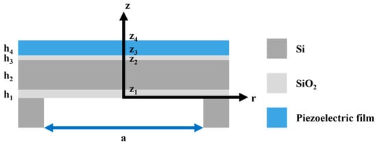
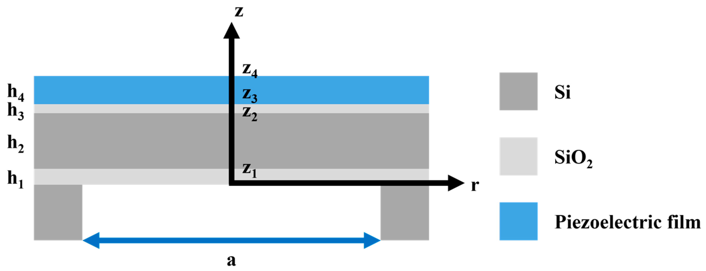
pMUTs typically operate near their resonant frequency, which corresponds to the peak electromechanical energy conversion efficiency and is a key parameter determining the device’s optimal performance. To validate the accuracy of the modeling and meshing procedures in the finite element simulations, the resonant frequency of a square-diaphragm pMUT with known analytical solutions was first calculated. The pMUT diaphragm can be approximated as a composite thin plate with all four edges clamped, as shown in Figure 2.
Figure 2.
Schematic of the composite diaphragm structure of the pMUT.
The resonant frequency of the pMUT was calculated using thin-plate vibration theory. Accordingly, the first-order resonant frequency of the composite vibrating diaphragm is expressed as [30,31]:
where D denotes the equivalent bending stiffness of the composite diaphragm, μ is the mass per unit area, A is a constant equal to 17.994, and a is the side length of the square diaphragm.
The equivalent bending stiffness D of the n-layer composite diaphragm is given by [30,31]:
where En and νn are the Young’s modulus and Poisson’s ratio of the n-th layer, respectively; zn−1 and zn denote the positions of the bottom and top surfaces of the n-th layer relative to the reference plane. During the bending vibration of the composite diaphragm, the lower portion is stretched while the upper portion is compressed, and the intermediate plane that undergoes no deformation is defined as the neutral plane z0, which can be determined by [32]:
where hn is the thickness of the n-th layer, is the plate modulus.
The mass per unit area μ (i.e., the areal density) of the composite diaphragm is calculated as [32]:
where ρn is the mass density of the n-th layer material.
In practical applications, pMUTs are often immersed in fluid media. According to the study by Jiang et al. [32] on square-diaphragm pMUTs in fluid environments, the resonant frequency is modified due to the added mass effect of the surrounding fluid, compared with that in air. The resonant frequency of the square composite diaphragm pMUT in a fluid medium is given by:
where ρfluid is the density of the fluid medium.
pMUTs can emit and receive ultrasonic signals through the direct and converse piezoelectric effects of the piezoelectric material. Hence, transmitting sensitivity and receiving sensitivity serve as key performance indicators for evaluating pMUTs. Transmitting sensitivity is determined by the mechanical displacement or sound pressure level generated under a given input voltage, reflecting the efficiency of the pMUT in converting electrical energy into acoustic signals when operating as a transmitter. Accordingly, the transmitting sensitivity Sv (μPa/V at the measuring distance) of a pMUT can be expressed as:
where d0 is the reference distance and pf is the sound pressure in the free field.
The transmitting sensitivity level (SVL) is expressed in decibels (dB) and calculated as:
where = 1 μPa/V at 1 m denotes the reference value of the transmitting sensitivity level.
Receiving sensitivity is defined as the ratio of the open-circuit voltage at the pMUT output to the free-field sound pressure, which reflects the efficiency of the pMUT in generating an output voltage per unit sound pressure when operating as a receiver. Hence, the receiving sensitivity (Me) of a pMUT can be expressed as:
where e0c is the open-circuit voltage at the pMUT output, and pf is the free-field sound pressure.
The receiving sensitivity level (Mel) is expressed in decibels (dB) and calculated as:
where Me0 = 1 V/μPa denotes the reference value of the receiving sensitivity level.
Loop gain is another critical parameter for evaluating pMUT performance, defined as the ratio of the actual received voltage to the input voltage. By calculating the loop gain, the combined effects of transmitting and receiving sensitivities can be assessed, providing a comprehensive characterization of the energy loss during both transmission and reception. It is expressed as:
Expressed in decibels (dB), the loop gain is given by:
Loop gain = SVL + Mel (dB)
2.2. Simulation and Optimization of the pMUT with an I-Shaped Composite Diaphragm
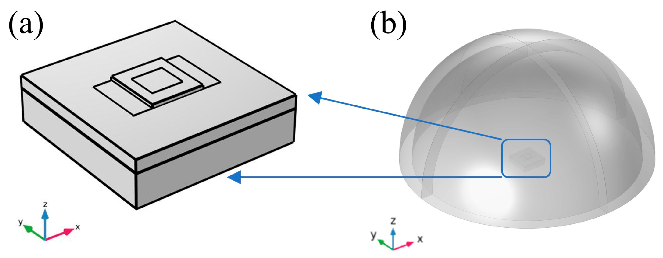
To analyze the performance of the PMUT in the ethanol domain, a hemispherical ethanol domain with a radius of 1000 μm (speed of sound: 1168 m/s) was established. A 100-μm-thick Perfectly Matched Layer (PML) was added around the periphery of the ethanol domain to simulate an infinite ethanol domain, as shown in Figure 3. In the Solid Mechanics module, fixed constraint boundary conditions were applied to the surrounding boundaries of the geometric model. To simulate the external environment for acoustic wave propagation, the outer surface of the ethanol domain was set as a far-field boundary.
Figure 3.
In the absolute ethanol domain: (a) vibration-sensitive configuration; (b) 3D finite element model of PMUT.
After completing the meshing and boundary condition setup, the modal analysis module of the finite element software was employed to compute the resonant frequency of the ZnO-based pMUT with a square diaphragm. The simulated resonant frequency in air was compared with the theoretical result derived above, as summarized in Table 3. It can be observed that the theoretical and simulated results are in good agreement, with the deviation falling within an acceptable range. This consistency validates the reliability of the finite element simulations, confirming their utility as a basis for pMUT design and analysis.
Table 3.
Comparison of theoretical and simulated resonant frequencies of the pMUT with a square diaphragm in air and ethanol media.
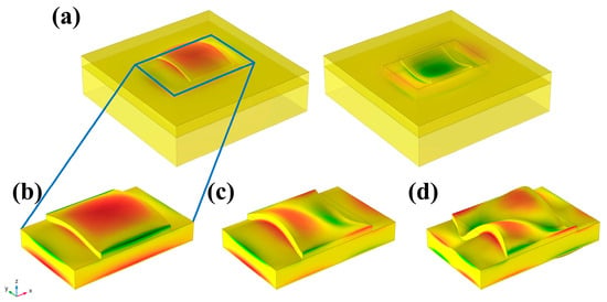
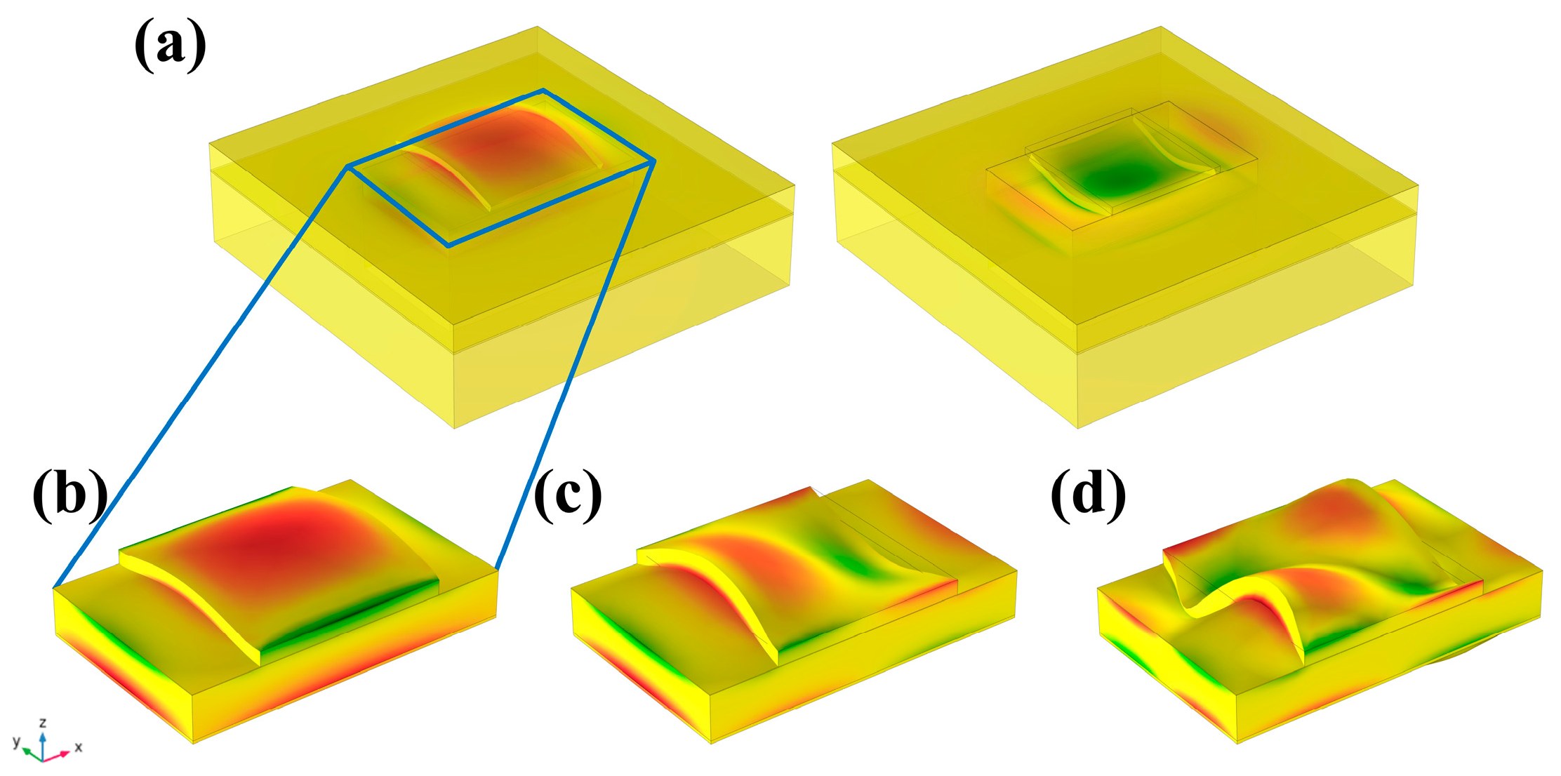
The first three vibration modes of the ZnO-based I-shaped composite diaphragm, as obtained from finite element simulations, are depicted in Figure 4. The first-order mode, characterized by a parabolic shape, is easier to excite and produces greater displacement and acoustic pressure. Hence, it was chosen for further investigation. Additionally, comparative simulations were carried out to evaluate the resonant frequencies of the I-shaped diaphragm structure with various piezoelectric materials in air and ethanol media, and the corresponding data are listed in Table 4. It can be observed that the resonant frequency of the ZnO-based PMUT is approximately 14% lower than that of the AlN-based counterpart.
Figure 4.
The first three vibration modes of the pMUT with an I-shaped diaphragm: (a) First-order vibration mode shapes of the composite diaphragm with the supporting structure; (b) First-order vibration mode shapes of the composite diaphragm alone; (c) second-order vibration mode shapes of the composite diaphragm alone; (d) third-order vibration mode shapes of the composite diaphragm alone.
Table 4.
Comparison of resonant frequencies of the pMUT with different piezoelectric materials.
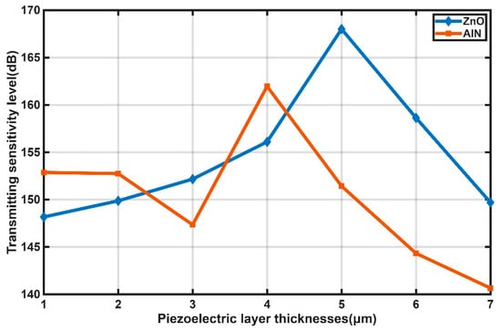
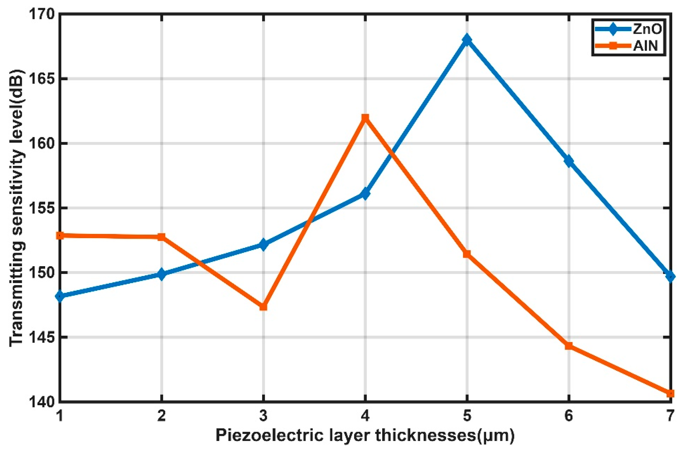
To enhance the performance of the pMUT with an I-shaped composite diaphragm, the influence of piezoelectric layer thickness on its sensitivity was investigated. The transmitting sensitivity level curves for pMUTs with different piezoelectric layer thicknesses are presented in Figure 5. Insufficient piezoelectric driving force was provided when the layer was overly thin, preventing effective bending of the composite diaphragm and resulting in low transmitting sensitivity. As the thickness increased, the transmitting sensitivity was generally improved. However, a further increase in thickness led to a reduction in transducer capacitance and thus a lower energy storage capacity, which in turn caused a decline in sensitivity. Consequently, an optimal thickness was identified to maximize the transmitting sensitivity. The maximum transmitting sensitivity level of the I-shaped pMUT was found to be 168.01 dB at a ZnO thickness of 5 μm, and 161.96 dB at an AlN thickness of 4 μm. It was therefore demonstrated that the ZnO-based pMUT achieved a 6.05 dB higher maximum transmitting sensitivity than the AlN-based counterpart, while the optimal ZnO thickness was only 1 μm larger. Moreover, the fabrication of a 5-μm-thick ZnO film was confirmed to be readily achievable with current manufacturing techniques.
Figure 5.
Transmitting sensitivity level curves of the pMUT for different piezoelectric layer thicknesses.
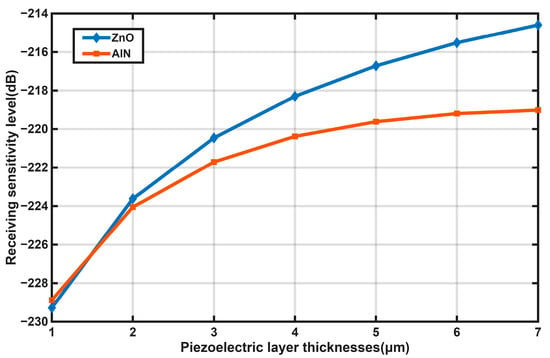
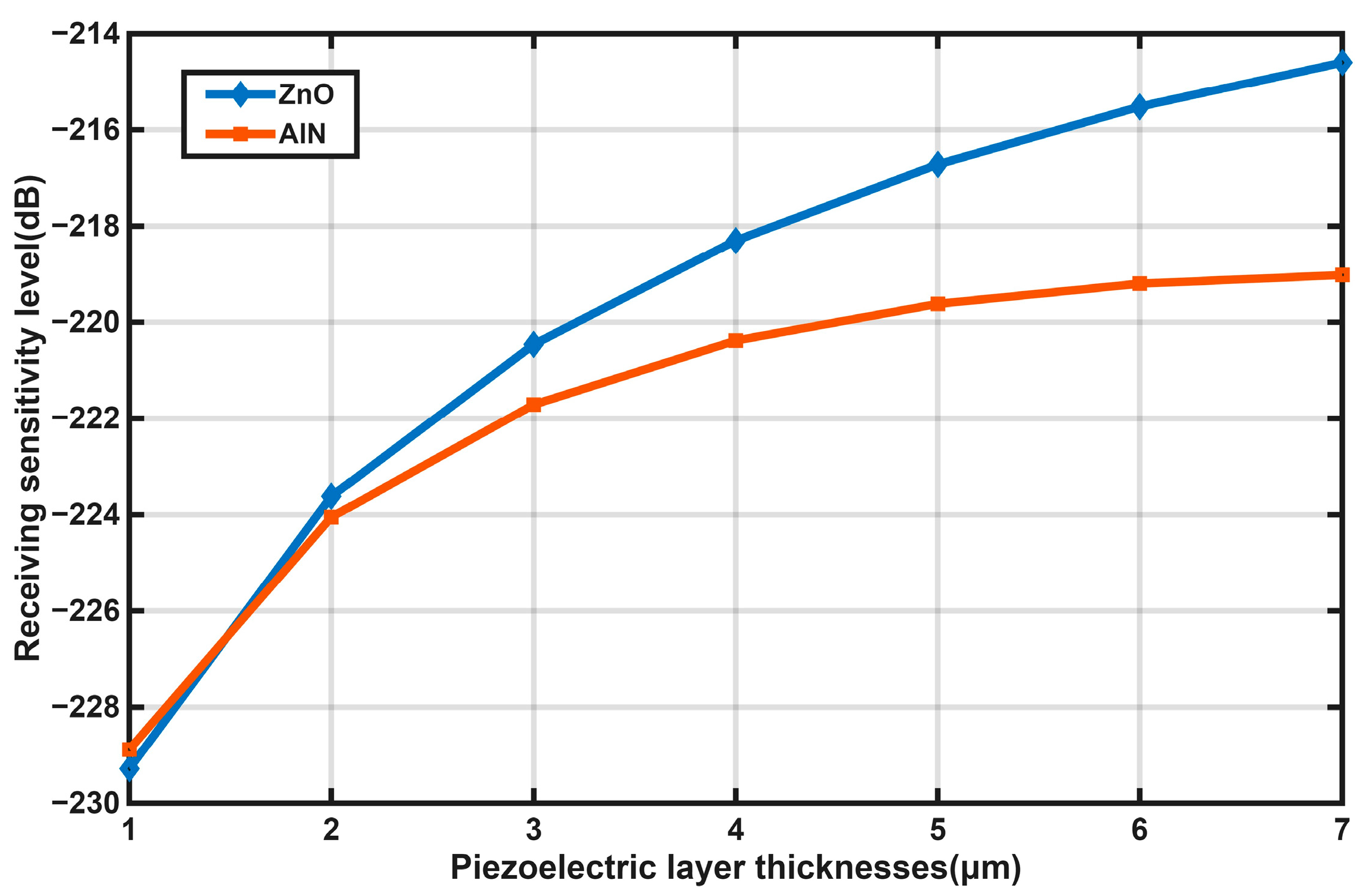
The receiving sensitivity level curves for pMUTs with different piezoelectric layer thicknesses are presented in Figure 6. When the piezoelectric layer was excessively thin, large stress was generated, while the output charge was limited and the capacitance was overly high, resulting in a small output voltage and thus a relatively low receiving sensitivity level. Generally, as the piezoelectric layer thickness increased, the neutral plane of the composite vibrating diaphragm was gradually shifted upward into the piezoelectric layer. Prior to the neutral plane reaching the piezoelectric layer, the output voltage was progressively increased with increasing piezoelectric layer thickness, leading to a generally rising trend in the receiving sensitivity level, which eventually leveled off. Overall, the receiving sensitivity of the ZnO-based pMUT was found to be consistently higher than that of the AlN-based counterpart across all thicknesses examined.
Figure 6.
Receiving sensitivity level curves of the pMUT for different piezoelectric layer thicknesses.
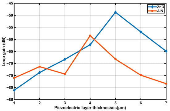
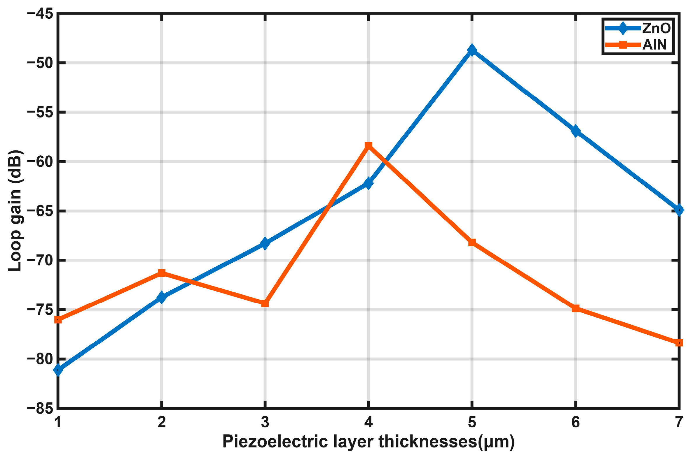
The loop gain curves of the pMUT for different piezoelectric layer thicknesses were calculated using Equation (11) and are presented in Figure 7. As the piezoelectric layer thickness was gradually increased, the loop gain was found to increase initially and then decrease. The maximum loop gain of the ZnO-based pMUT was determined to be −49.04 dB at a ZnO thickness of 5 μm, while that of the AlN-based pMUT reached −58.42 dB at an AlN thickness of 4 μm. It was therefore demonstrated that the ZnO-based pMUT achieved a 9.38 dB higher maximum loop gain than the AlN-based counterpart.
Figure 7.
Loop gain curves of the PMUT for different piezoelectric layer thicknesses.
In summary, the ZnO-based pMUT was demonstrated to exhibit superior performance to the AlN-based counterpart in terms of transmitting sensitivity, receiving sensitivity, and loop gain, while the optimal ZnO thickness was found to be only 1 μm higher than that of AlN and could be readily obtained by magnetron sputtering. Therefore, ZnO was selected as the piezoelectric transduction material for the PMUT in this work.
3. Fabrication of the ZnO-Based pMUT
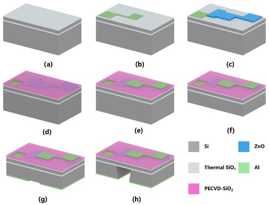
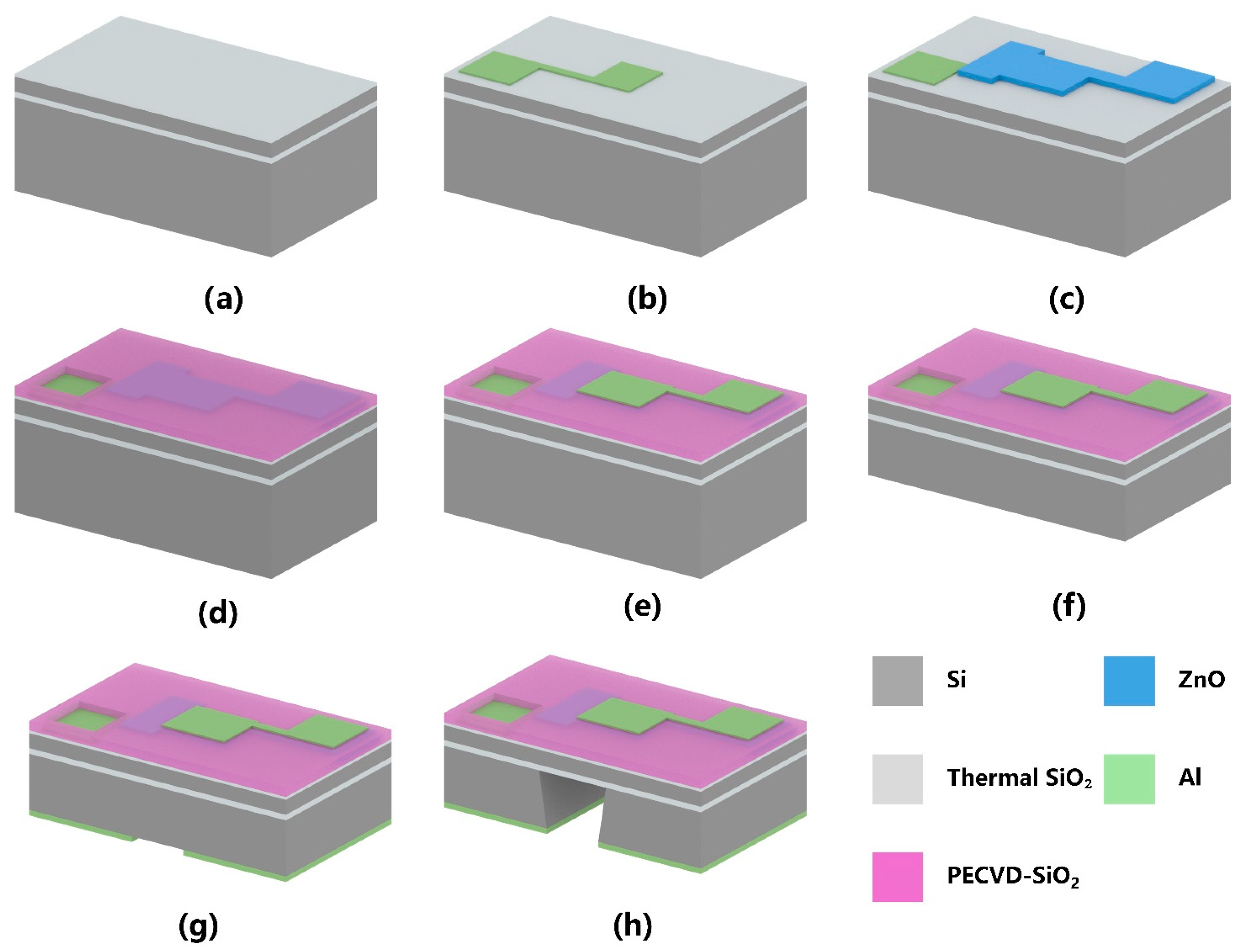
On the basis of the above structural optimization, a fabrication process flow was designed for the ZnO-based pMUT with an I-shaped composite diaphragm, as depicted in Figure 8. The detailed fabrication sequence is summarized as follows: (1) An SOI wafer was prepared, with SiO2 layers formed on both surfaces by thermal oxidation [Figure 8a]. (2) A bottom Al electrode was sputtered and patterned on the front side [Figure 8b]. (3) A 5-μm-thick ZnO piezoelectric layer was deposited by magnetron sputtering (Ar: O2 flow ratio of 10:20, substrate temperature of 200 °C) and patterned on the front side [Figure 8c]. (4) A SiO2 insulation layer was deposited on the ZnO layer by Plasma-Enhanced Chemical Vapor Deposition (PECVD) [Figure 8d]. (5) A top Al electrode was defined by a lift-off process and patterned [Figure 8e]. (6) The backside silicon layer was thinned to a target thickness by Chemical Mechanical Planarization (CMP) [Figure 8f]. (7) An Al hard mask for Deep Reactive Ion Etching (DRIE) was deposited and patterned on the backside [Figure 8g]. The double-side lithography system has an alignment accuracy of 1 μm. (8) The backside silicon was dry-etched by DRIE (654 cycles, He flow rate of 9.45–10.8 sccm) until the etch was stopped at the buried oxide layer, thereby forming the pMUT cavity and releasing the composite diaphragm. The fabrication was thus completed, as shown in Figure 8h.
Figure 8.
Fabrication process flow of the I-shaped diaphragm pMUT: (a) SiO2 formed by thermal oxidation; (b) Bottom Al electrode deposition and patterning; (c) ZnO piezoelectric layer deposition and patterning; (d) SiO2 insulation layer deposition by PECVD; (e) Top Al electrode deposition and patterning; (f) Backside silicon layer thinning by CMP; (g) Al hard mask deposition and patterning on the backside silicon substrate; (h) Bulk silicon etching by DRIE.
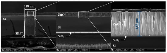
To better observe the cavity etching condition of the fabricated pMUT chips, the chips were cross-sectioned along the center of the diaphragm, and the cavity morphology was characterized by scanning electron microscopy (SEM), as shown in Figure 9. An etching verticality of 88.9° was measured for the pMUT cavity, and the cavity interior was observed to be clean. The backside cavity was found to be accurately aligned with the front-side patterns, indicating that the double-side photolithography alignment process was well performed.
Figure 9.
SEM image of the pMUT sidewall morphology.
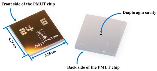
The wafer was cut by stealth dicing into individual pMUT chips. The active area of each chip was only 260 µm × 580 µm, whereas the final die size was 0.25 cm × 0.25 cm for convenient packaging and testing, as presented in Figure 10. The obtained chips exhibited complete structural integrity, well-defined patterns, and precise dimensional accuracy, indicating that the fabrication process was successfully implemented.
Figure 10.
Photograph of a single pMUT chip.
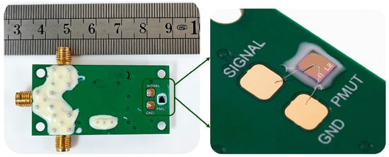
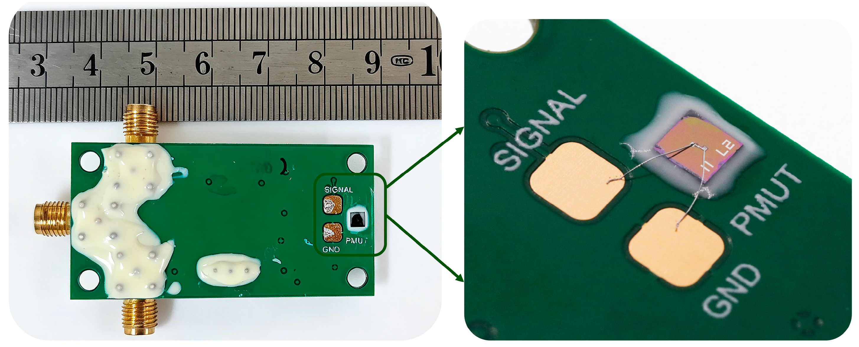
The pMUT chip was electrically connected to the backend matching circuit (with a gain of 24.91 dB) using an ultrasonic aluminum wire bonder. Subsequently, sealant was applied around the chip and on the surface of the circuit to protect the device from the external liquid environment. The completed pMUT is shown in Figure 11.
Figure 11.
Photograph of the packaged pMUT device.
4. Measurement and Analysis
4.1. Resonant Frequency Measurement
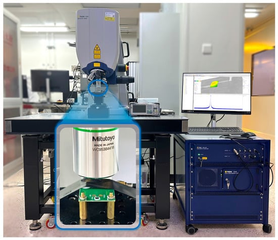
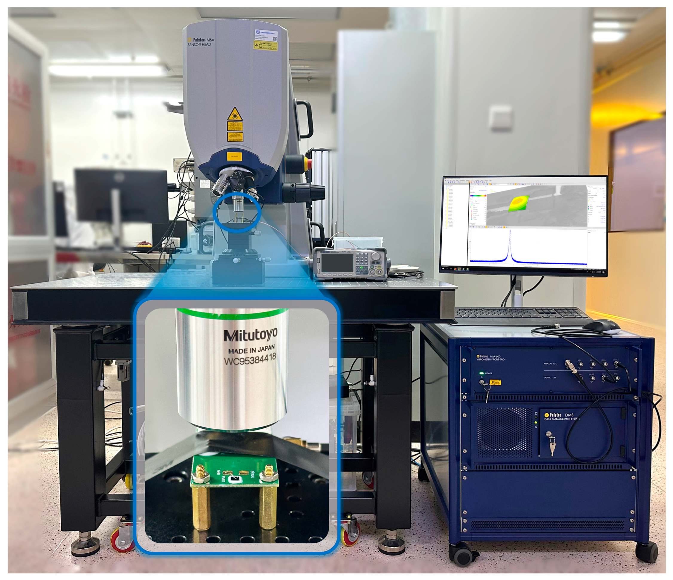
The mechanical vibration of the pMUT in air was characterized using a Polytec MSA-600 laser Doppler vibrometer (LDV, Polytec GmbH, Waldbronn, Germany), as shown in Figure 12. During the measurement, the device was firmly mounted on an XYZ positioning stage to eliminate displacement-induced errors. The laser beam was focused onto the diaphragm surface through an optical microscope objective. Under a 10 V driving voltage, the diaphragm was excited into vibration, and resonance was observed. The laser beam incident on the vibrating diaphragm was reflected, and the reflected light, carrying Doppler frequency shifts, was processed via interferometry to convert the Doppler signal into an electrical output. This enabled the acquisition of the displacement frequency spectrum, which was scanned over the range of 1 MHz to 25 MHz.
Figure 12.
Schematic diagram of the LDV measurement setup for the pMUT in air.
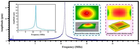
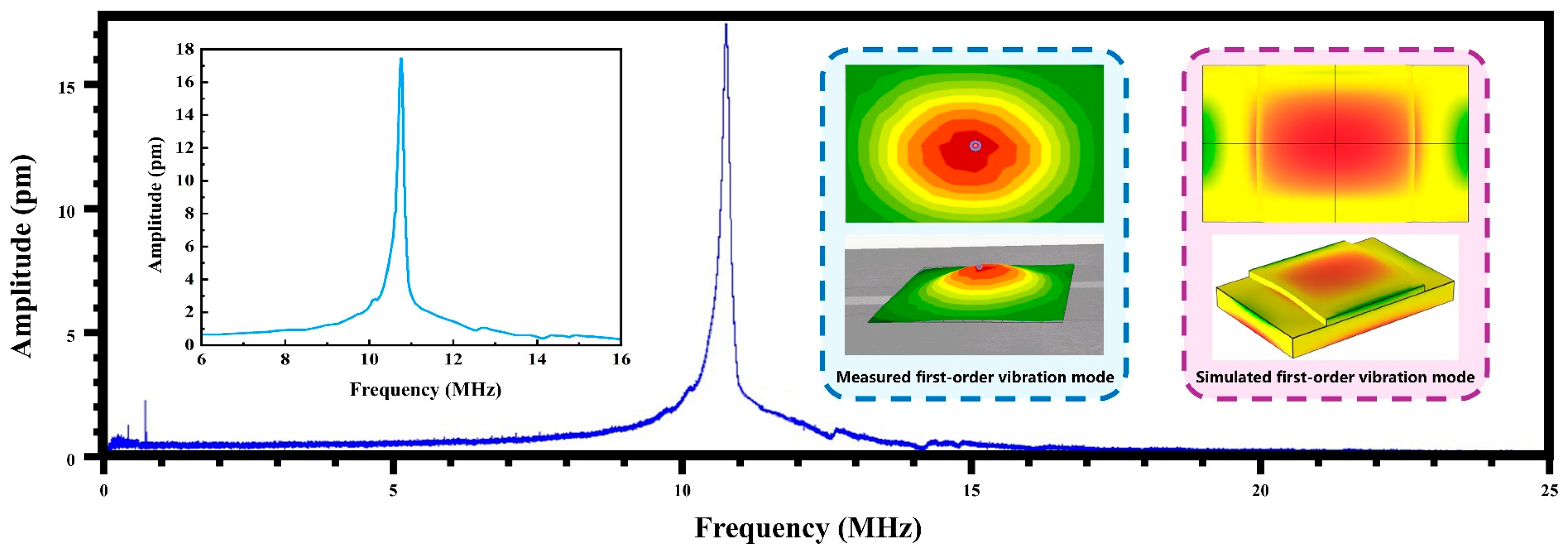
The LDV measurement results of the pMUT in air are presented in Figure 13. A resonant frequency of 10.71 MHz was observed, with a corresponding maximum vibration displacement of 17.45 pm. The vibration mode was identified as the first-order mode, which was found to be consistent with the simulation results. However, a discrepancy of 5.4 MHz was noted between the measured resonant frequency in air and the simulated value. This deviation was primarily attributed to various factors inherent in the MEMS fabrication process. On one hand, the etching verticality achieved by DRIE was not optimal, leading to a 7% enlargement of the diaphragm dimensions. Simulations showed that this enlargement alone reduced the resonant frequency by approximately 52%. On the other hand, the resonant frequency was reduced by approximately 48% during the fabrication process owing to residual stress and discrepancies between the actual material parameters and the simulated values due to thin-film deposition. These combined factors contributed to the reduction in the resonant frequency measured in air.
Figure 13.
Displacement frequency spectrum and first-order vibration mode of the pMUT in air: experimental and simulation results.
4.2. Sensitivity Measurement
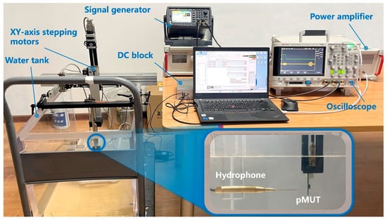
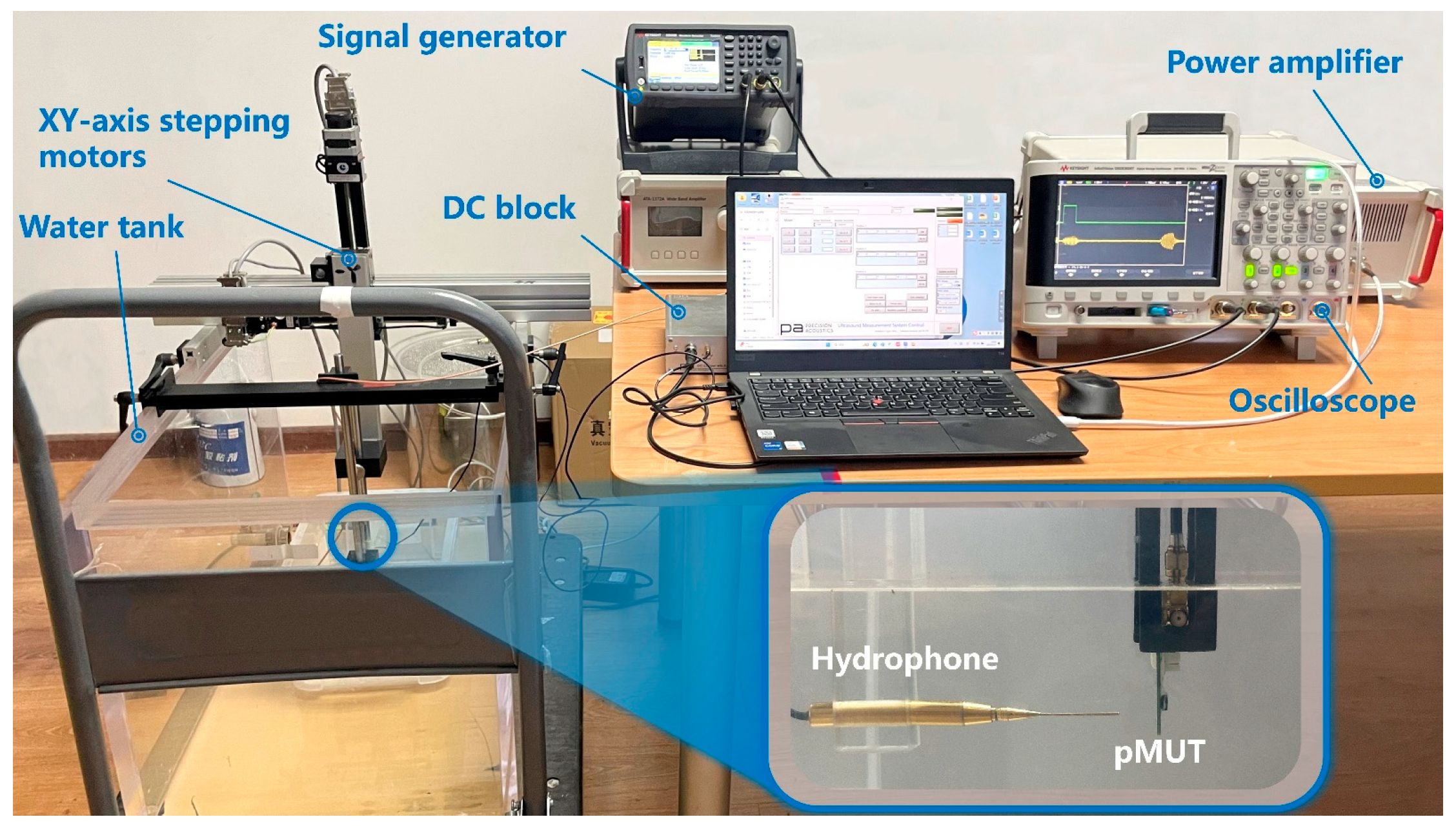
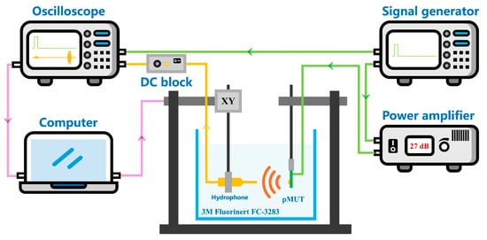
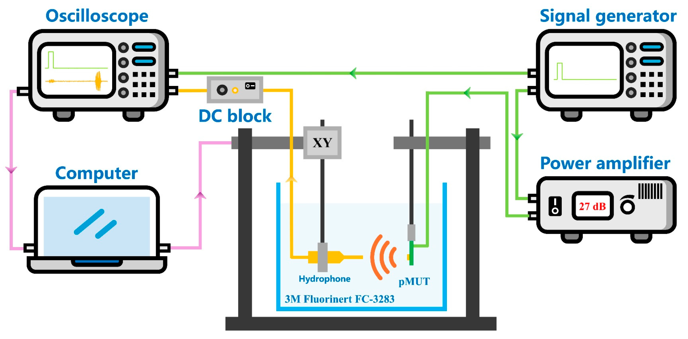
To better simulate the actual operating conditions of pMUTs in medical imaging and underwater detection, liquid–environment tests were performed in this section. The testing platform is schematically illustrated in Figure 14. Electronic fluorinated fluid (FC-3283) was chosen as the immersion medium over deionized water or anhydrous ethanol, because the exposed electrodes and metal pads on the circuit board could otherwise be subject to contamination and electrical leakage. The density and sound velocity of FC-3283 are given as ρFC−3283 = 1.8 g/mL and cFC−3283 = 565 m/s, respectively [33,34]. A power amplifier was used to boost the driving signal, ensuring that the pMUT diaphragm was sufficiently energized to radiate acoustic waves. A standard NH0500 needle hydrophone (Precision Acoustics Ltd., Dorchester, UK) served as the receiving transducer, and a V311 immersion probe (Olympus, Tokyo, Japan) was used as the transmitting source.
Figure 14.
Test platform schematic of the pMUT.
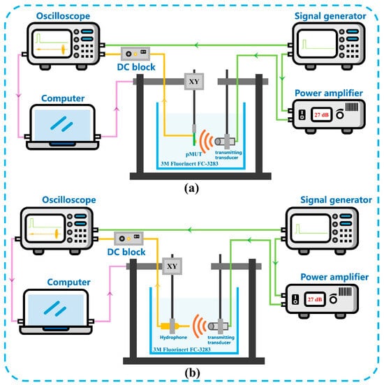
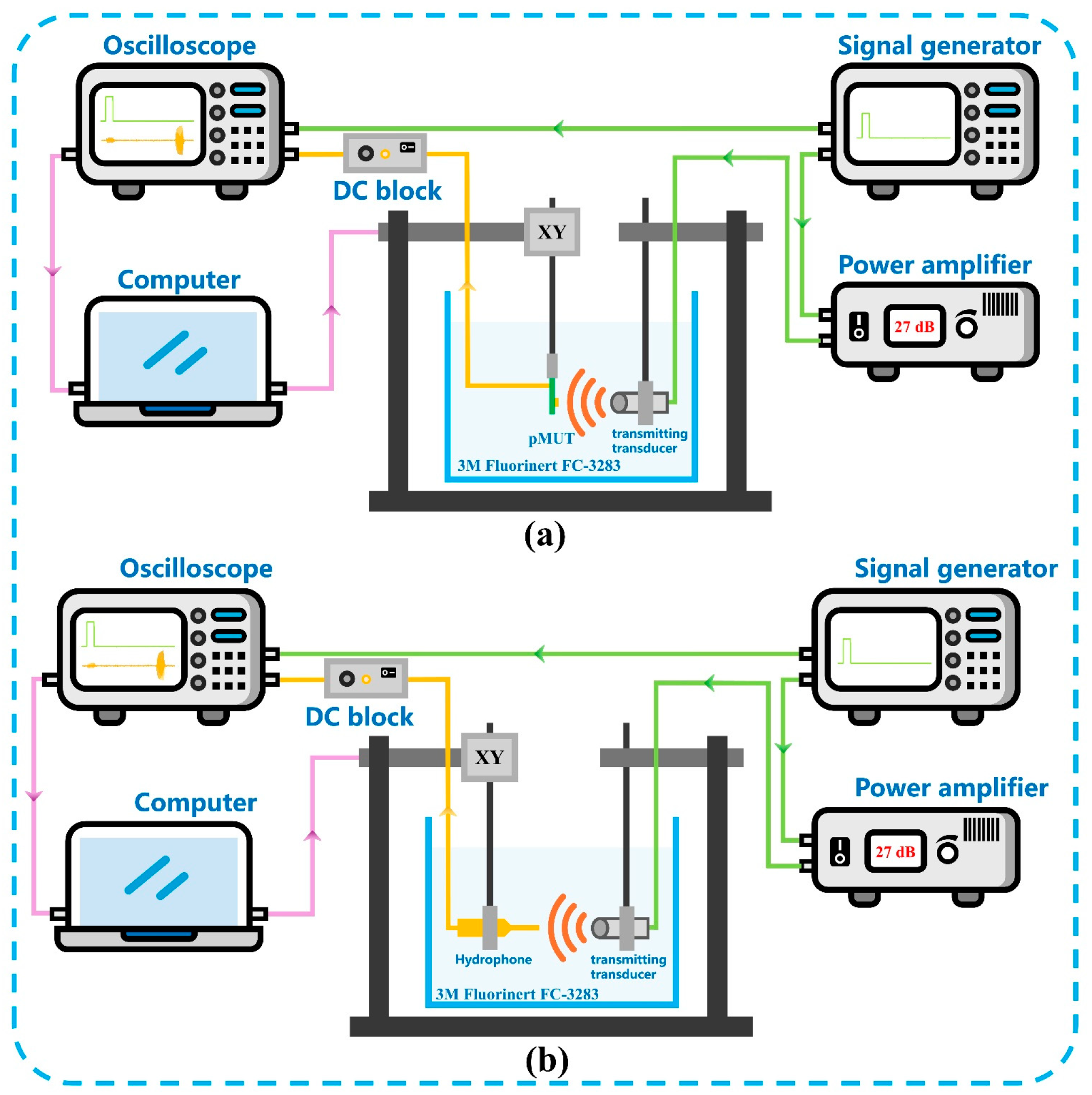
A comparison method was adopted for the measurement of the pMUT receiving sensitivity level. Acoustic pulses were generated by a transmitting transducer and captured by the fabricated ZnO-based pMUT with an I-shaped composite diaphragm at a predetermined distance, after which the same pulses were recorded at the identical position using a reference hydrophone, as depicted in Figure 15.
Figure 15.
Schematic diagram of receiving sensitivity testing of the pMUT with an I-shaped diaphragm: (a) Reception measurement using the fabricated pMUT; (b) Reception measurement using the standard hydrophone.
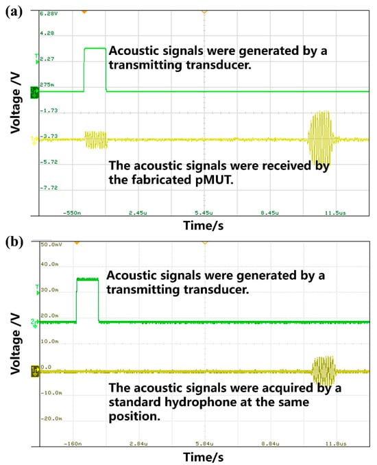
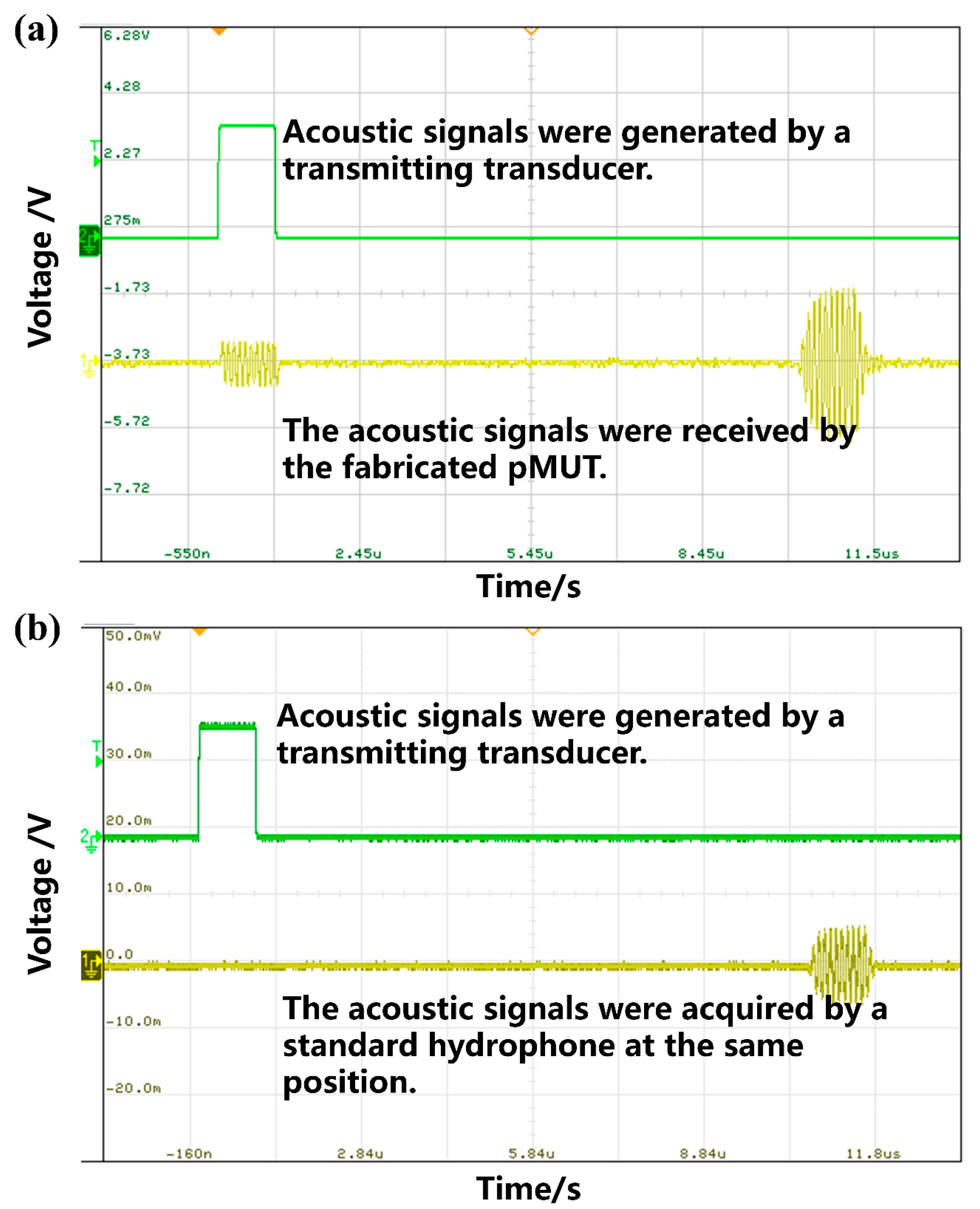
In the test, the transmit frequency was set to 10 MHz, and a 10-cycle sinusoidal burst was emitted by the signal generator with a peak-to-peak voltage of 1.2 V. The signals received by the fabricated pMUT and the reference hydrophone are presented in Figure 16a and Figure 16b, respectively. Upon calibration, the pMUT output amplitude was measured as 22.64 mV, whereas the hydrophone output was 11.7 mV, corresponding to a hydrophone sensitivity of 0.404 μV/Pa. Consequently, the receiving sensitivity of the fabricated pMUT was derived as:
Figure 16.
Measurement results of receiving sensitivity of a device: (a) The fabricated pMUT; (b) a calibrated hydrophone.
According to Equations (7) and (12), the receiving sensitivity level of the fabricated pMUT was determined to be −242.1 dB (re 1 V/μPa, with an amplification of 24.91 dB).
For the transmitting sensitivity level measurement, the fabricated pMUT was employed as the transmitting transducer, and a standard hydrophone was used as the receiving transducer, as illustrated in Figure 17.
Figure 17.
Schematic diagram of transmitting sensitivity testing of the fabricated pMUT.
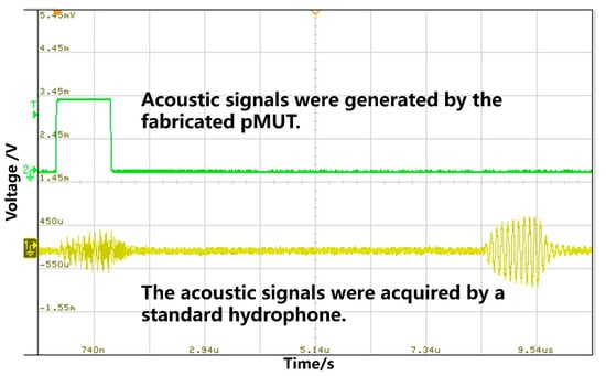
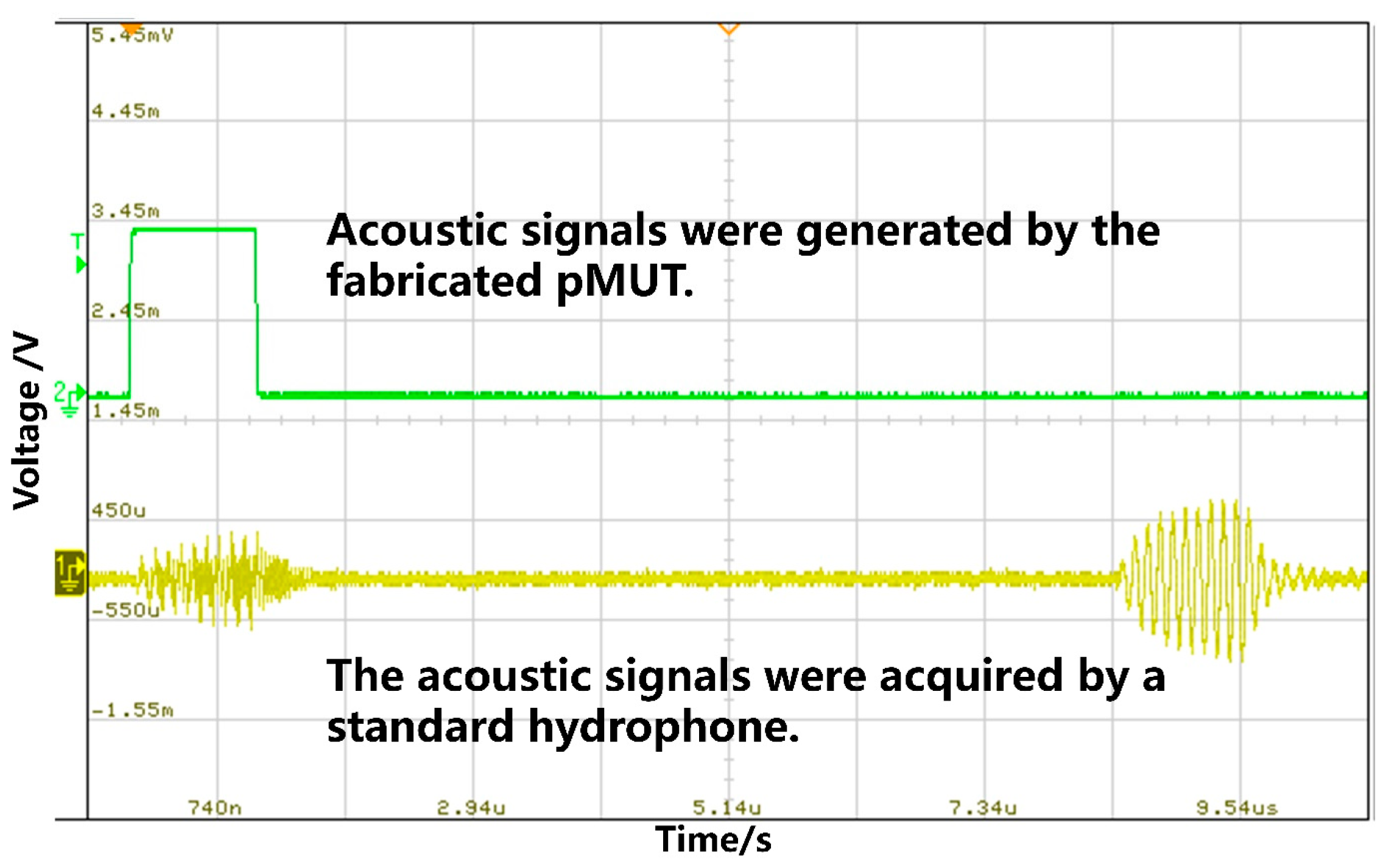
In the transmitting sensitivity test, a 10 MHz, 10-cycle sinusoidal burst was emitted with a peak-to-peak voltage of 1.2 V. The waveform measured by the fabricated pMUT is presented in Figure 18. Following calibration, the transmitting sensitivity level was calculated as 173.5 dB (re 1 μPa/V) at an equivalent distance of 5 mm.
Figure 18.
Measurement results of the transmitting sensitivity of the fabricated pMUT.
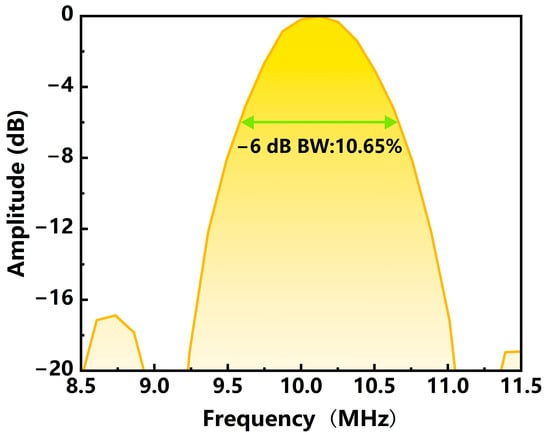
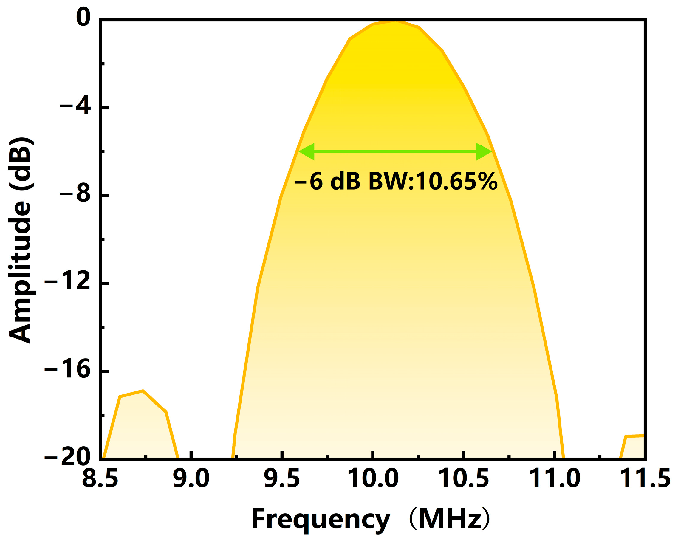
The frequency response of the fabricated pMUT was derived from the FFT analysis of the transmitting sensitivity curve, as presented in Figure 19. A −6 dB bandwidth of 10.65% was obtained, and the resonant frequency in FC-3283 was found to be 10 MHz, showing a deviation of 0.71 MHz from that measured in air. These results indicate that for pMUTs with a relatively thick diaphragm, the resonant frequency is less affected by the surrounding fluid medium.
Figure 19.
The frequency response of the fabricated pMUT.
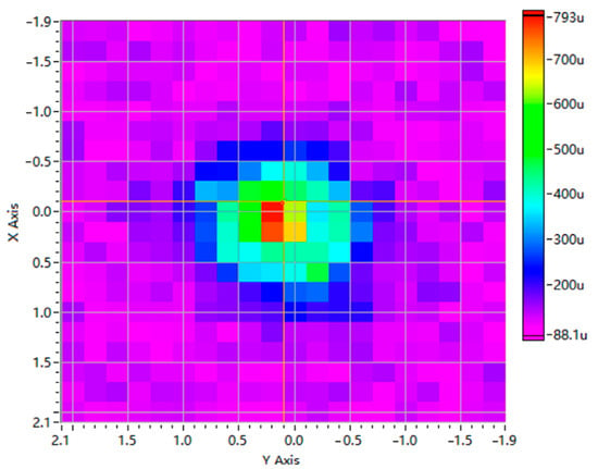
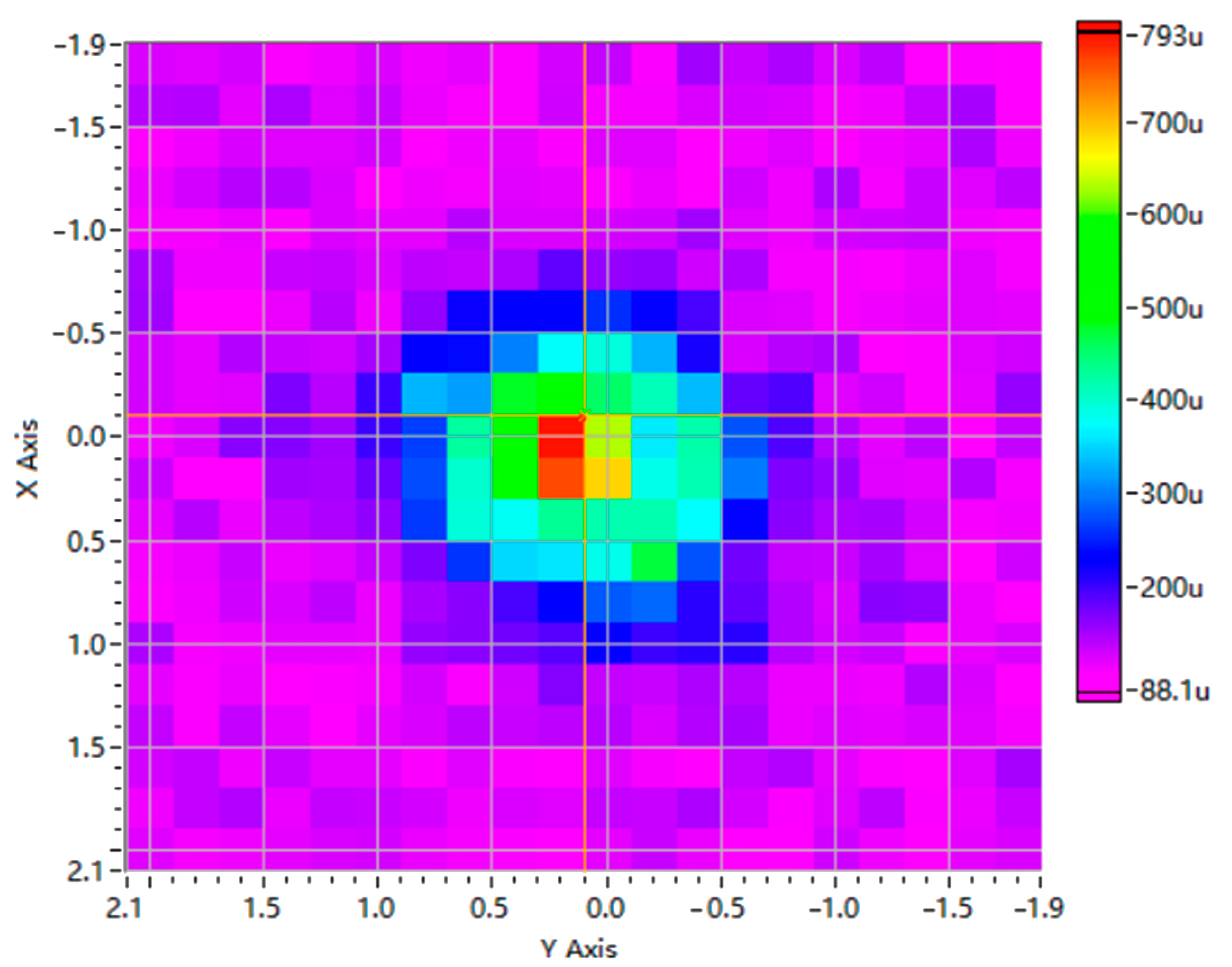
The acoustic field of the pMUT was scanned using computer-controlled XY stage stepper motors. A scanner–device distance of 5 mm and a scanning range of 2 mm × 2 mm were used. The measured distribution is shown in Figure 20. The results indicate that the ZnO-based pMUT with an I-shaped composite diaphragm showed directional characteristics in its sound field.
Figure 20.
The acoustic field distribution map of the fabricated pMUT (the scanner–device distance was 5 mm, and the scanning range was 2 mm × 2 mm).
4.3. Performance Comparison
We also compared the performance of our fabricated device with previously reported results, as summarized in Table 5. Since the transmitting sensitivity Sv depends strongly on the measurement distance r, the values reported in different studies were normalized for comparison under identical conditions. Specifically, Sv was multiplied by r to obtain the Sv·r value, with the unit unified as Pa·m/V. As can be seen from Table 5, some reported measurements were performed in air, whereas most were conducted in liquid media. The resonant frequencies measured in air are generally significantly higher than those measured in liquid. Since liquid environments more closely resemble the practical operating conditions of pMUTs, performance comparisons under liquid conditions are more relevant to practical applications. In addition, frequency and sensitivity are inherently mutually restrictive—higher frequency generally leads to lower sensitivity. Hence, devices with comparable frequencies are typically compared in terms of sensitivity to assess their overall performance. It can be seen that our device achieves a normalized transmitting sensitivity (Sv·r value) of 2.37 Pa·m/V, surpassing all the reference devices listed. Compared with AlN-based pMUTs operating at similar frequencies (0.156 Pa·m/V), this value is approximately 15 times higher; compared with PZT-based counterparts (0.0436 Pa·m/V), it is about 54 times higher. Moreover, the performance advantage reaches two to three orders of magnitude over conventional low-frequency, large-size PVDF-based piezoelectric transducers. These results further validate the effectiveness of the I-shaped diaphragm design in releasing film residual stress and enhancing the effective bending deformation of the piezoelectric layer, thereby significantly improving the electromechanical conversion efficiency and acoustic radiation capability. In practical underwater or medical imaging applications, higher transmitting sensitivity allows a higher source level to be obtained at the same driving voltage or power, resulting in stronger echo signals. For underwater applications, this can increase the detection or communication range and improve noise immunity. For medical imaging, it can increase the penetration depth, improve image quality, and allow the driving voltage and power consumption to be reduced. In addition, our device operates at a frequency of 10 MHz, demonstrating considerable potential for high-resolution imaging and precision inspection. Our device, by elevating the operating frequency while resolving the inherent trade-off between frequency and sensitivity commonly observed in conventional structures, achieves a synergistic optimization of both high frequency and high sensitivity. In terms of receiving sensitivity, our device attains a value of 0.782 mV/kPa, outperforming the AlN-based pMUT and the LiNbO3-based pMUT. This ensures efficient electromechanical conversion of weak echo signals, contributing to an improved signal-to-noise ratio in ultrasonic systems. Furthermore, the diaphragm cell size of our device is only 0.11 mm * 0.07 mm, providing a structural basis for high-density array integration and meeting the miniaturization requirements of portable ultrasonic systems.
Table 5.
Performance comparison between the fabricated pMUT and previously reported devices.
5. Discussion
In this work, a ZnO-based pMUT with an I-shaped structure was developed. Residual stress was released, and the effective bending deformation of the piezoelectric film was enhanced, so that a relatively high sensitivity is maintained at a relatively high resonant frequency. Simulation results show that the ZnO-based pMUT is superior to the AlN-based counterpart in key metrics including transmitting sensitivity level, receiving sensitivity level, and loop gain. The fabricated ZnO-based PMUT with an I-shaped structure exhibits a measured resonant frequency of 10 MHz in FC-3283, a transmitting sensitivity level of 173.5 dB (re 1 μPa/V), a receiving sensitivity level of −242.1 dB (re 1 V/μPa), a loop gain of −68.6 dB, and a −6 dB bandwidth of 10.65%, thereby validating the feasibility of the structural design and material selection. As shown by the performance comparison in Section 4.3, favorable performance was achieved by the proposed pMUT in terms of resonant frequency, transmitting sensitivity, and receiving sensitivity. These results confirm that the proposed device alleviates the inherent trade-off between frequency and sensitivity commonly observed in conventional structures while raising the operating frequency, thereby achieving synergistic optimization of high frequency and high sensitivity. In practical applications, this enables the detection or communication range and noise immunity to be effectively increased for underwater applications, or the penetration depth and image quality to be improved for medical imaging.
6. Conclusions
In this work, a pMUT with an I-shaped diaphragm was developed to effectively release residual stress of the piezoelectric film, enabling the transducer to simultaneously achieve a relatively high resonant frequency and sensitivity. Simulation results demonstrate that the ZnO-based pMUT outperforms its AlN-based counterpart in terms of transmitting sensitivity, receiving sensitivity, and loop gain. Through optimization of the structural parameters and key fabrication techniques, the fabrication and performance characterization of the ZnO-based pMUT were successfully accomplished. Measurement results show that, in FC-3283, the fabricated device exhibits a resonant frequency of 10 MHz, a transmitting sensitivity level of 173.5 dB (re 1 μPa/V), a receiving sensitivity level of −242.1 dB (re 1 V/μPa), a loop gain of −68.6 dB, and a −6 dB bandwidth of 10.65%. Compared with previously reported devices, our transducer achieves comprehensive improvements in transmitting sensitivity, operating frequency, and receiving sensitivity while maintaining a compact diaphragm footprint, thereby resolving the inherent trade-off between frequency and sensitivity commonly observed in conventional designs. These results not only confirm the effectiveness of the I-shaped diaphragm configuration but also highlight the potential of the proposed pMUT for applications in underwater detection, ultrasonic imaging, and beyond.
Author Contributions
Conceptualization, J.L. and Q.F.; methodology, Q.Y.; software, Y.H.; validation, Q.Y., Q.F., and Y.H.; formal analysis, Q.Y.; investigation, Q.F.; resources, Y.H.; data curation, Q.Y.; writing—original draft preparation, Q.Y.; writing—review and editing, Q.F.; visualization, Q.F.; supervision, J.L.; project administration, J.L.; funding acquisition, J.L. All authors have read and agreed to the published version of the manuscript.
Funding
This research was funded by the Yangtze River Delta Science and Technology Innovation Community Joint Research Program of China (Grant No. 2023CSJZN0200).
Institutional Review Board Statement
Not applicable.
Informed Consent Statement
Not applicable.
Data Availability Statement
The original contributions presented in this study are included in the article. Further inquiries can be directed to the corresponding author.
Conflicts of Interest
The authors declare no conflicts of interest.
References
- Rybyanets, A.N. New methods and transducer designs for ultrasonic diagnostics and therapy. In Advanced Materials: Manufacturing, Physics, Mechanics and Applications; Springer International Publishing: Berlin/Heidelberg, Germany, 2016; pp. 603–620. [Google Scholar] [CrossRef] [Scilit]
- Chapelon, J.Y.; Cathignol, D.; Cain, C.; Ebbini, E.; Kluiwstra, J.U.; Sapozhnikov, O.A.; Fleury, G.; Berriet, R.; Chupin, L.; Guey, J.L. New piezoelectric transducers for therapeutic ultrasound. Ultrasound Med. Biol. 2000, 26, 153–159. [Google Scholar] [CrossRef] [Scilit] [PubMed]
- Wong, S.H.; Kupnik, M.; Watkins, R.D.; Butts-Pauly, K.; Khuri-Yakub, B.T. Capacitive micromachined ultrasonic transducers for therapeutic ultrasound applications. IEEE Trans. Biomed. Eng. 2009, 57, 114–123. [Google Scholar] [CrossRef] [Scilit] [PubMed]
- Wang, C.; Chen, Z.W.; Wu, J.W.; Wen, X.; Chen, Y. Research Progress of Novel Ultrasonic Transducers in the Biomedical Field. J. Guangdong Univ. Technol. 2025, 42, 1–14. (in Chinese). [Google Scholar]
- He, J.; Chen, Z.; Luo, X. A Bayesian estimation-based uncertainty quantification of flaws in steel welds detected by ultrasound phased array. J. Phys. Conf. Ser. 2020, 1592, 012011. [Google Scholar] [CrossRef] [Scilit]
- Song, H.; Popovics, J.S. Contactless ultrasonic wavefield imaging to visualize near-surface damage in concrete elements. Appl. Sci. 2019, 9, 3005. [Google Scholar] [CrossRef] [Scilit]
- Li, X.; Liu, Y.; Liu, Z.Y.; Chu, J.W.; Song, Y.C.; Yu, T.; Zhao, J.F. A hydrate blockage detection apparatus for gas pipeline using ultrasonic focused transducer and its application on a flow loop. Energy Sci. Eng. 2020, 8, 1770–1780. [Google Scholar] [CrossRef] [Scilit]
- Cao, X.; Yang, H.; Wang, M.; Hu, Z.-G.; Wu, Z.-L.; Wang, Y.; Liu, J.-F.; Zhou, X.; Li, J.; Lao, C.; et al. Integrated optomechanical ultrasonic sensors with nano-Pascal-level sensitivity. Light Sci. Appl. 2026, 15, 171. [Google Scholar] [CrossRef] [Scilit] [PubMed]
- Chen, Z.; Hua, Q.; Xu, J.; Shen, G. A Submersible Soft Robot with Ultrasonic Echolocation Capabilities. In Proceedings of the 2025 9th IEEE Electron Devices Technology & Manufacturing Conference (EDTM), Hong Kong, China, 9–12 March 2025. [Google Scholar] [CrossRef] [Scilit]
- Brassier, P.; Hosten, B.; Vulovic, F. High-frequency transducers and correlation method to enhance ultrasonic gas flow metering. Flow Meas. Instrum. 2001, 12, 201–211. [Google Scholar] [CrossRef] [Scilit]
- Zhu, K.; Chen, X.Y.; Qu, M.J.; Yang, D.F.; Hu, L.; Xu, J.H.; Xie, J. An ultrasonic flowmeter for liquid flow measurement in small pipes using AlN piezoelectric micromachined ultrasonic transducer arrays. J. Micromech. Microeng. 2020, 30, 125010. [Google Scholar] [CrossRef] [Scilit]
- Izquierdo, A.; del Val, L.; Villacorta, J.J. Pedestrian detection using a MEMS acoustic array mounted on a moving vehicle. Sens. Actuators A Phys. 2024, 376, 115586. [Google Scholar] [CrossRef] [Scilit]
- Schlegl, T.; Bretterklieber, T.; Neumayer, M.; Zangl, H. Combined capacitive and ultrasonic distance measurement for automotive applications. IEEE Sens. J. 2011, 11, 2636–2642. [Google Scholar] [CrossRef] [Scilit]
- Liu, T.J.; Young, M.S. Eliminating contaminants with a piezoelectric transducer in the design of low-cost smart kitchen range hoods. IEEE Sens. J. 2002, 2, 314–321. [Google Scholar] [CrossRef]
- Yan, Q.B.; Xia, Q.; Wang, Y.D.; Zhou, P.Z.; Zeng, H.C. URadio: Wideband ultrasound communication for smart home applications. IEEE Internet Things J. 2021, 9, 13113–13125. [Google Scholar] [CrossRef] [Scilit]
- Zhao, L.; Lu, Y.P. Piezoelectric micromachined ultrasonic transducers for consumer electronics applications. In Proceedings of the 2023 7th IEEE Electron Devices Technology & Manufacturing Conference (EDTM), Seoul, Republic of Korea, 7–10 March 2023; IEEE: New York, NY, USA, 2023; pp. 1–3. [Google Scholar] [CrossRef] [Scilit]
- Joseph, J.; Ma, B.; Khuri-Yakub, B.T. Applications of capacitive micromachined ultrasonic transducers: A comprehensive review. IEEE Trans. Ultrason. Ferroelectr. Freq. Control 2021, 69, 456–467. [Google Scholar] [CrossRef] [Scilit] [PubMed]
- He, Y.S.; Wan, H.T.; Jiang, X.N.; Peng, C. Piezoelectric micromachined ultrasound transducer technology: Recent advances and applications. Biosensors 2022, 13, 55. [Google Scholar] [CrossRef] [Scilit] [PubMed]
- Chen, J.K.; Cheng, X.Y.; Chen, C.C.; Li, P.C.; Liu, J.H.; Cheng, Y.T. A capacitive micromachined ultrasonic transducer array for minimally invasive medical diagnosis. J. Microelectromech. Syst. 2008, 17, 599–610. [Google Scholar] [CrossRef]
- Sadeghpour, S.; Joshi, S.V.; Wang, C.; Kraft, M. Novel phased array piezoelectric micromachined ultrasound transducers (PMUTs) for medical imaging. IEEE Open J. Ultrason. Ferroelectr. Freq. Control 2022, 2, 194–202. [Google Scholar] [CrossRef] [Scilit]
- Moisello, E.; Novaresi, L.; Sarkar, E.; Malcovati, P.; Costa, T.L.; Bonizzoni, E. PMUT and CMUT devices for biomedical applications: A review. IEEE Access 2024, 12, 18640–18657. [Google Scholar] [CrossRef] [Scilit]
- Qiu, Y.Q.; Gigliotti, J.V.; Wallace, M.; Griggio, F.; Demore, C.E.M.; Cochran, S.; Trolier-McKinstry, S. Piezoelectric micromachined ultrasound transducer (PMUT) arrays for integrated sensing, actuation and imaging. Sensors 2015, 15, 8020–8041. [Google Scholar] [CrossRef] [Scilit] [PubMed]
- Luan, G. Progress in piezoelectric MEMS ultrasonic transducers. Appl. Acoust. 2012, 31, 161–170. (In Chinese) [Google Scholar]
- Li, J.H.; Ren, W.; Fan, G.X.; Wang, C.H. Design and fabrication of piezoelectric micromachined ultrasound transducer (pMUT) with partially-etched ZnO film. Sensors 2017, 17, 1381. [Google Scholar] [CrossRef] [Scilit] [PubMed]
- Xu, T.; Zhao, L.; Jiang, Z.; Guo, S.; Li, Z.; Yang, P.; Luo, G.; Sun, L.; Zhang, L. Equivalent Circuit Model for a Large Array of Coupled Piezoelectric Micromachined Ultrasonic Transducers With High Emission Performance. IEEE Trans. Ultrason. Ferroelectr. Freq. Control 2021, 68, 718–733. [Google Scholar] [CrossRef] [Scilit] [PubMed]
- Xu, T.; Zhao, L.; Jiang, Z.; Guo, S.; Li, Z.; Luo, G.; Sun, L.; Zhang, L. An Analytical Equivalent Circuit Model for Optimization Design of a Broadband Piezoelectric Micromachined Ultrasonic Transducer With an Annular Diaphragm. IEEE Trans. Ultrason. Ferroelectr. Freq. Control 2019, 66, 1760–1776. [Google Scholar] [CrossRef] [Scilit] [PubMed]
- Wang, T.; Sawada, R.; Lee, C. A piezoelectric micromachined ultrasonic transducer using piston-like membrane motion. IEEE Electron Device Lett. 2015, 36, 957–959. [Google Scholar] [CrossRef] [Scilit]
- Chen, X.; Chen, D.; Liu, X.; Yang, D.; Pang, J.; Xie, J. Transmitting sensitivity enhancement of piezoelectric micromachined ultrasonic transducers via residual stress localization by stiffness modification. IEEE Electron Device Lett. 2019, 40, 796–799. [Google Scholar] [CrossRef] [Scilit]
- Yu, Q.; Fan, G.; Ren, W.; Fan, Q.; Ti, J.; Li, J.; Wang, C. PZT-Film-Based Piezoelectric micromachined ultrasonic transducer with I-Shaped composite diaphragm. Micromachines 2022, 13, 1597. [Google Scholar] [CrossRef] [Scilit] [PubMed]
- Fan, G. Research on Piezoelectric Micromachined Ultrasonic Transducers and 1D Arrays; University of Chinese Academy of Sciences: Beijing, China, 2016. (In Chinese) [Google Scholar]
- Reddy, J.N. Mechanics of Laminated Composite Plates: Theory and Analysis; CRC Press: Boca Raton, FL, USA, 1997. [Google Scholar]
- Jiang, X.; Lu, Y.; Tang, H.Y.; Tsai, J.M.; Ng, E.J.; Daneman, M.J.; Boser, B.E.; Horsley, D.A. Monolithic ultrasound fingerprint sensor. Microsyst. Nanoeng. 2017, 3, 17059. [Google Scholar] [CrossRef] [Scilit] [PubMed]
- Selfridge, A.R. Approximate material properties in isotropic materials. IEEE Trans. Sonics Ultrason. 1985, 32, 381–394. [Google Scholar] [CrossRef] [Scilit]
- Zhao, L.; Xia, J.; Yang, C.; Lu, Y. Modeling and experimental studies of mutual acoustic radiation effect on PMUT array. Sens. Actuators A Phys. 2024, 377, 115677. [Google Scholar] [CrossRef] [Scilit]
- Chare, C.; Gijsenbergh, P.; Jeong, Y.; Heremans, P.; Genoe, J.; Cheyns, D. High performance large-area polymeric PMUT phased arrays in air. In Proceedings of the 2022 IEEE International Ultrasonics Symposium (IUS), Venice, Italy, 10–13 October 2022; IEEE: New York, NY, USA, 2022; pp. 1–4. [Google Scholar] [CrossRef] [Scilit]
- Meng, X.; Ji, W.; Sun, C.; Xing, Z.; Guo, Y.; Wang, T.; Pan, X.; Shuai, Y.; Sun, X.; Zhang, W. Design of High-Sensitivity Piezoelectric Micromachined Ultrasonic Transducer Based on Single-Crystal Lithium Niobate Thin Films. IEEE Trans. Electron Devices 2025, 72, 5623–5630. [Google Scholar] [CrossRef] [Scilit]
- Tang, H.-Y.; Lu, Y.; Jiang, X.; Ng, E.J.; Tsai, J.M.; Horsley, D.A.; Boser, B.E. 3-D ultrasonic fingerprint sensor-on-a-chip. IEEE J. Solid State Circuits 2026, 51, 2522–2533. [Google Scholar] [CrossRef] [Scilit]

Disclaimer/Publisher’s Note: The statements, opinions and data contained in all publications are solely those of the individual author(s) and contributor(s) and not of MDPI and/or the editor(s). MDPI and/or the editor(s) disclaim responsibility for any injury to people or property resulting from any ideas, methods, instructions or products referred to in the content. |
© 2026 by the authors. Licensee MDPI, Basel, Switzerland. This article is an open access article distributed under the terms and conditions of the Creative Commons Attribution (CC BY) license.