


Highlights
What are the main findings?
- Integrated cyber-physical architecture coordinates aerial and ground agents.
- UAV LiDAR sensor fusion maps a 500 m tunnel in <8 min in zero visibility.
What are the implications of the main findings?
- Autonomous deployment enables operations to start 50–80% earlier.
- Digital orchestration eliminates 100% of human exposure to post-blast risks.
- System reduces daily operational time by 8% with an ROI of 1–7 months.
Abstract
Post-blast operations in tunnel construction represent a critical bottleneck due to mandatory downtime and hazardous environmental conditions. This study addresses these challenges by developing and validating an integrated cyber–physical architecture that coordinates an autonomous Unmanned Aerial Vehicle (UAV) and an Autonomous Wheel Loader (AWL) under the supervision of a Digital Twin acting as central operational digital interface. Specifically, this technology was designed to access the tunnel, evaluate post-blasting conditions, and initiate operations during mandatory exclusion periods for personnel. The system was validated in a realistic, Global Navigation Satellite System (GNSS)-denied tunnel environment emulating post-detonation visibility constraints. The results demonstrate that the aerial agent successfully navigated and mapped the excavation front in less than 8 min, establishing a shared coordinate system for the ground machinery. Through this collaborative workflow, the autonomous deployment enabled operations to commence 50% to 80% earlier than conventional manual procedures. Furthermore, the system reduced daily operational time by approximately 8%, with an estimated return on financial investment between one and seven months. Overall, the proposed framework eliminates human exposure during high-risk inspections and transforms the fragmented excavation cycle into a continuous, data-driven process.
1. Introduction
Underground construction plays a pivotal role in the development of modern infrastructure, facilitating essential urban transportation networks and enabling the efficient utilisation of subsurface space. This sector is currently undergoing a phase of rapid expansion, driven by accelerating global urbanisation and the transition towards more resilient infrastructure systems. Recent market analyses reflect this momentum, forecasting a compound annual growth rate of approximately 6.8% for the global tunnel construction market between 2023 and 2028 [1], with certain regional estimates projecting growth as high as 9% [1]. However, the execution of these subterranean works presents significant technical and operational challenges. The environment is inherently hostile, characterised by the absence of GNSS (Global Navigation Satellite System) signals, poor visibility, the presence of dust, and the potential accumulation of harmful gases. These factors, combined with severe communication constraints, critically affect navigation, sensing capabilities, and mission autonomy [2,3].
Consequently, these conditions complicate planning and operations while significantly elevating safety risks for the workforce. Comparative analyses between underground and surface construction activities indicate that accident rates in subterranean works can be considerably higher, in some instances more than double, due to restricted spatial configurations, complex geological conditions, and limited evacuation options [4,5]. Within this context, the post-blast phase, which encompasses cavity inspection, geological characterisation, debris removal, and material transport, represents a persistent bottleneck in the tunnelling cycle. Traditionally, this phase relies on a series of sequential manual operations that must be executed by specialised personnel. However, these activities cannot commence immediately, as they are contingent upon the completion of mandatory ventilation periods to ensure atmospheric safety, often depending directly on on-site observations [6,7].
This dependency on human intervention introduces significant limitations, including exposure to potential ground instability, oxygen deficiency, and airborne dust [4,8]. Furthermore, the requisite downtime for ventilation and the subsequent sequential execution of inspection and cleaning tasks results in substantial periods of inactivity. This directly impacts the project’s efficiency by lengthening excavation cycles and reducing overall productivity [9,10]. Compounding these operational inefficiencies is the difficulty of obtaining reliable real-time data. Measurements in such environments are often qualitative rather than quantitative, hindering accurate decision-making and delaying the planning of subsequent project phases [11]. Moreover, the lack of integrated digital information constrains interoperability with management platforms, impeding effective coordination between on-site operations and control systems [12,13,14].
In response to these challenges, the automation of operations through advanced robotic technologies and autonomous navigation is increasingly recognised as a decisive step towards a safer and more resilient construction paradigm [15,16,17].
Over the last decade, significant advances have been made in specific domains. Unmanned Aerial Vehicles (UAVs) have been successfully deployed for tunnel inspection and mapping, capable of performing close-range visual assessments and generating detailed three-dimensional reconstructions using sensor fusion approaches like light detection and ranging (LiDAR) and vision-based Simultaneous Localization and Mapping (SLAM). Nevertheless, UAV performance remains strongly challenged by environmental conditions such as low illumination and airborne particulates [2,18,19]. In these post-blast scenarios, relying solely on standard Mobile Laser Scanning (MLS) is insufficient; high concentrations of suspended matter cause significant laser backscattering and attenuation, introducing noise and ‘phantom obstacles’ that compromise navigation safety [3]. Therefore, to ensure robust data acquisition where single-modality perception fails [15], the proposed architecture moves beyond varying geometric lidar-inertial odometry by integrating Thermal Imaging, which is unaffected by visible obscurants, and specific intensity-based filtering algorithms.
In parallel, the deployment of autonomous or semi-autonomous ground vehicles for debris removal has shown promising results. Robotic haulers and dumpers have demonstrated reliable navigation in controlled pilot operations, offering the potential to reduce manual labour [20,21,22,23]. At the decision-making level, Digital Twin (DT) technologies have evolved from static models to dynamic platforms that integrate sensor data and operational status together with tasks orchestration and decision support capabilities. These systems are essential for enhancing situational awareness and traceability; however, their integration with autonomous robotic platforms remains in an early stage, and the orchestration of multi-agent operations in complex tunnel environments is still largely unexplored [13,24,25,26].
Despite these individual advancements in autonomous mapping, robotics, and digital supervision, a critical technological gap persists: the fragmentation of current solutions. Recent literature has introduced promising concepts for UAV-UGV coordination; for instance, exploring vision-based collaboration architectures for autonomous site preparation in surface construction [27]. Additionally, significant theoretical advances have been proposed regarding adaptive cooperative localization methods for heterogeneous robots operating in satellite-denied environments [28,29,30]. However, these approaches largely remain theoretical or rely on external infrastructure, failing to address the specific complexities of heavy machinery operating in realistic underground scenarios. Most existing developments focus on isolated tasks, such as aerial inspection, debris removal, or monitoring, without providing a comprehensive framework that unifies these processes. To overcome these limitations, this research, framed within the BEEYONDERS project [31], proposes a fully integrated solution. Consequently, there is currently no existing approach that fully combines aerial mapping, ground-based transport, and digital orchestration within a single operational architecture suitable for GNSS-denied and low-visibility environments [15,32,33,34]. This lack of integration prevents the deployment of fully autonomous systems capable of managing the post-blast phase as a seamless and optimised process.
The present study aims to bridge this gap by demonstrating the feasibility and advantages of an integrated robotic–digital approach for autonomous post-blast tunnel operations. The proposed methodology validates the coordinated interaction between UAV and an autonomous Wheel Loader (AWL), linking them to a Digital Twin environment to enable data-driven decision-making. This architecture is designed to overcome the limitations of fragmented systems by ensuring that perception, cooperative localisation, and decision support function as a unified entity.
The main contribution of this work is the proposal and validation of a novel cyber-physical architecture for heterogeneous robotic coordination in GNSS-denied environments. Unlike previous studies that focus on isolated robotic tasks, this research formalizes a reusable methodology where the Digital Twin acts not merely as a visualizer, but as an active orchestrator closing the data loop between aerial perception and ground actuation. Specifically, the study addresses the scientific challenge of semantic interoperability and shared localization between incompatible robotic ecosystems (ROS1/ROS2) without external infrastructure, validating the system’s robustness in a realistic post-blast simulation. Overall, the results provide new insights into the potential of integrated robotic and digital technologies to increase safety, reduce operational downtime, and boost productivity in future tunnel construction processes.
2. Materials and Methods
The tunnel demonstrator implements an integrated cyber–physical architecture designed to automate post-blast operations. This system coordinates a heterogeneous robotic fleet, comprising an UAV for autonomous inspection and an AWL for material handling, under the supervision of a cloud-edge DT.
Serving as the central intelligence layer, the DT moves beyond static geometric modelling to create a dynamic ecosystem that merges sensing, actuation, and analytics [35,36,37]. Functionally, the architecture assigns three primary roles to the DT: (1) a supervisory layer that coordinates the UAV, AWL, and human operators; (2) an integrative layer that fuses heterogeneous datasets, including LiDAR point clouds and robotic telemetry, into a coherent 3D environment; and (3) an analytical layer that applies data-driven models for key performance indicator (KPI) computation and predictive performance evaluation [38].
To support these functions in a GNSS-denied environment, the system employs a hybrid edge–cloud configuration. This structure guarantees low-latency responsiveness for safety-critical operations while ensuring scalability for long-term data processing [39,40]. The resulting architecture facilitates a closed-loop data flow where 3D maps generated by the UAV are processed and transmitted to the AWL to enable precise autonomous navigation and debris removal.
2.1. UAV Subsystem
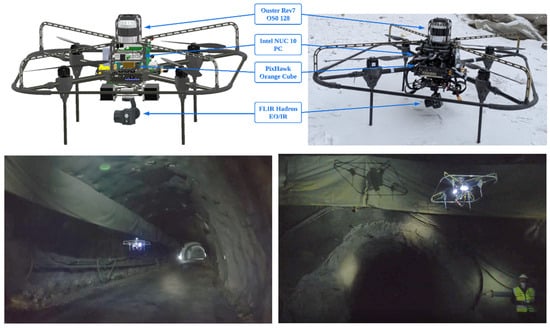
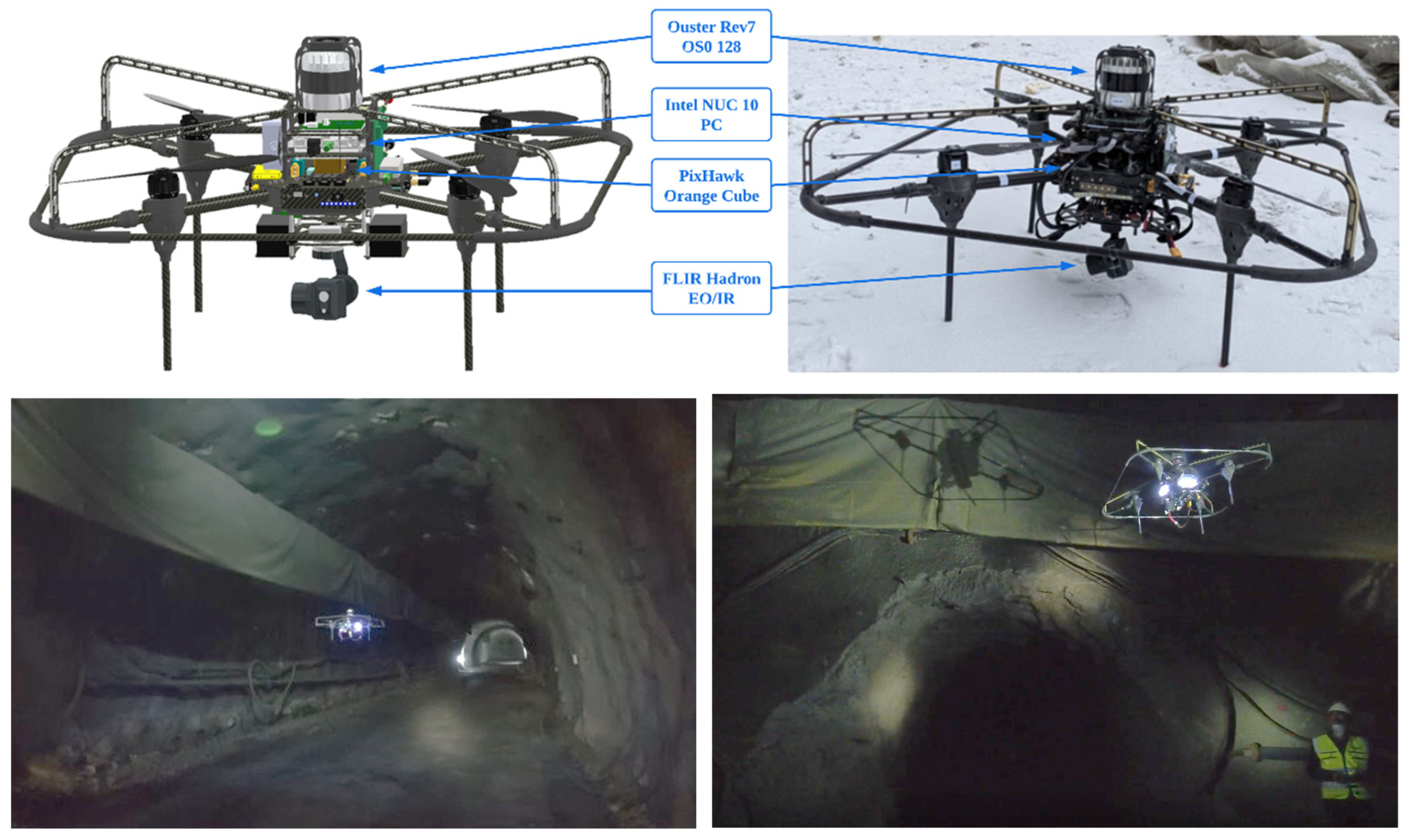
In the framework of this research, a custom multirotor platform has been specifically developed to operate in confined tunnel environments. The design prioritizes a compact and functional configuration, aiming to maximize performance and accessibility while maintaining robustness. Specifically, after a thorough analysis of component distribution, a quadrotor layout was selected to optimize the weight-to-space ratio; consequently, the UAV can operate with high stability during exploration and surveillance missions in hard-to-reach areas. Furthermore, the modular layout allows for precise adjustment of the center of mass to enhance flight dynamics under variable payload configurations. Regarding operational resilience in harsh tunnel environments, the platform features a custom protective fairing specifically designed to shield internal electronics from dust and small particles, alongside a cage system to mitigate risks during close-proximity flight. The resulting aircraft configuration and its deployment in the test environment are illustrated in Figure 1. Specific mechanical details and physical dimensions are provided in the Supplementary Information (Section S1).
Figure 1.
Custom Aerial Robot, CADRIN (top) and aerial robot navigating autonomously inside of the tunnel (bottom).
To execute fully autonomous operations in GNSS-denied and low-visibility conditions, the aircraft is equipped with a comprehensive sensor payload. Perception relies on a 3D LiDAR Ouster OS0-128 (Ouster Inc., San Francisco, CA, USA), which provides a 128-scan resolution point cloud at 10 Hz alongside internal inertial data at 125 Hz. Note that, for safety reasons, the sensor is enclosed in a protection cage; therefore, minor occlusions are handled by the software stack. In addition, for inspection and thermal analysis, a Teledyne FLIR Hadron 640R dual camera (Teledyne FLIR LLC., Wilsonville, OR, USA) is integrated into a Gremsy G-Hadron gimbal (Gremsy, Ho Chi Minh City, Vietnam). This setup stabilizes both the radiometric thermal sensor (640 × 512 resolution, 30 Hz) and the RGB camera (1080p, 60 FPS), significantly reducing vibrations to ensure high-quality imagery essential for the operator’s situational awareness. Additionally, computational tasks are distributed hierarchically to ensure redundancy and efficiency: a high-performance onboard computer handles the high-level autonomy algorithms and SLAM, while a dedicated secondary board manages sensor interfacing and video streaming. To facilitate robust communication, the system employs a dual-antenna configuration ensuring continuous telemetry to the mesh nodes. Low-level flight control is executed on an industrial-grade autopilot, which provides raw, high-frequency inertial measurement unit (IMU) data critical for the stabilization loops. Detailed hardware specifications, including computing unit models and component distribution, are provided in the Supplementary Information (Section S1).
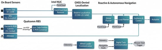
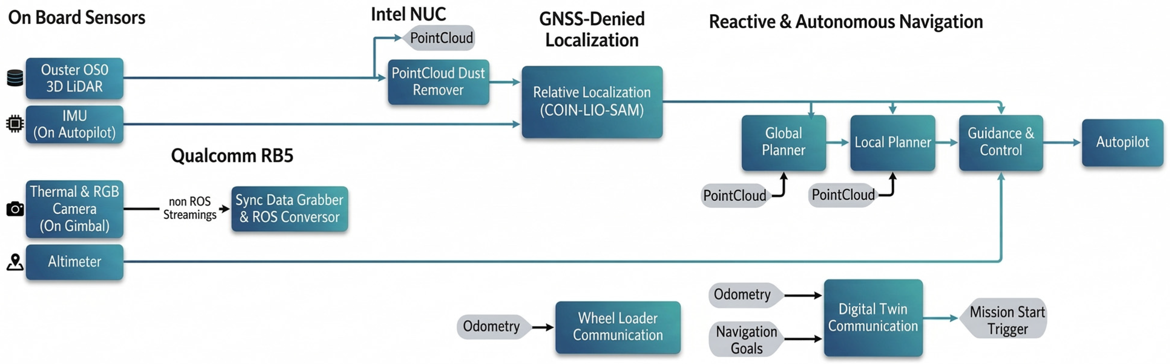
The software architecture, depicted in Figure 2, is modularized into two primary subsystems executed on the onboard computer: GNSS-denied localization and reactive navigation. In this context, a critical component for operating in post-blast conditions is the PointCloud Dust Remover module. Since suspended particles can be misinterpreted as obstacles, this module filters out noise before it reaches the mapping stack. To filter out residual noisy points caused by dust clouds while preserving valid non-dust points, the intensity threshold for clustering was determined through manual analysis of data collected during multiple flight tests in degraded visibility. Additionally, a region of interest (ROI) is defined around the sensor to discard near-field artifacts, as such noise was observed to occur predominantly at specific distances from the sensor.
Figure 2.
Software Architecture of Aerial Robot.
Regarding localization, the system must maintain accurate state estimation without external infrastructure. Based on a prior analysis of state-of-the-art LiDAR-inertial odometry for subterranean environments [41], the COIN-LIO algorithm was initially selected [42]. However, the standard implementation of COIN-LIO executes the prediction step of the tightly coupled iterated Kalman filter only upon the arrival of each new LiDAR scan. This limits the output state estimation to 10 Hz, which is insufficient for providing responsive control references in confined spaces. To overcome this limitation, the system employs COIN-LIO-SAM, a developed extension that integrates COIN-LIO into a factor graph optimization framework utilizing IMU pre-integration, similar to the approach used in LIO-SAM [43]. Hence, this fusion enables state estimation at the IMU frequency of 100 Hz, significantly enhancing the overall responsiveness and safety of the platform.
Finally, the navigation and guidance system coordinate three interconnected modules to enable safe flight in unknown environments. The global planner utilizes a volumetric exploration algorithm to generate optimal paths for autonomously mapping the unknown space [44]. To ensure operational safety within the tunnel geometry, the maximum exploration path length is strictly constrained to 8 m. Consequently, the UAV maintains a safe distance from walls and obstacles while keeping the trajectory centered within the tunnel cross-section. Furthermore, to reduce exploration downtime and sustain a consistent flight speed, subsequent exploration paths are generated proactively before the UAV reaches the end of the current segment. Real-time trajectory generation is handled by Fast-Planner [45], which computes collision-free paths by integrating path-based optimization with topologically calculated routes derived from the filtered LiDAR data. This allows the system to adapt instantaneously to dynamic obstacles. In short, the guidance layer utilizes a Finite-State Machine (FSM) to manage mission logic, coupled with a Cascade proportional–integral–derivative controller (PID) that translates the local planner’s trajectory references into precise actuator commands for the low-level autopilot [46].
2.2. AWL Subsystem
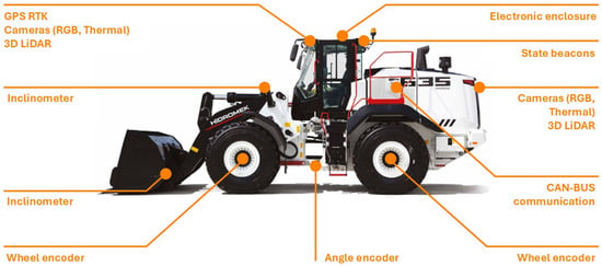
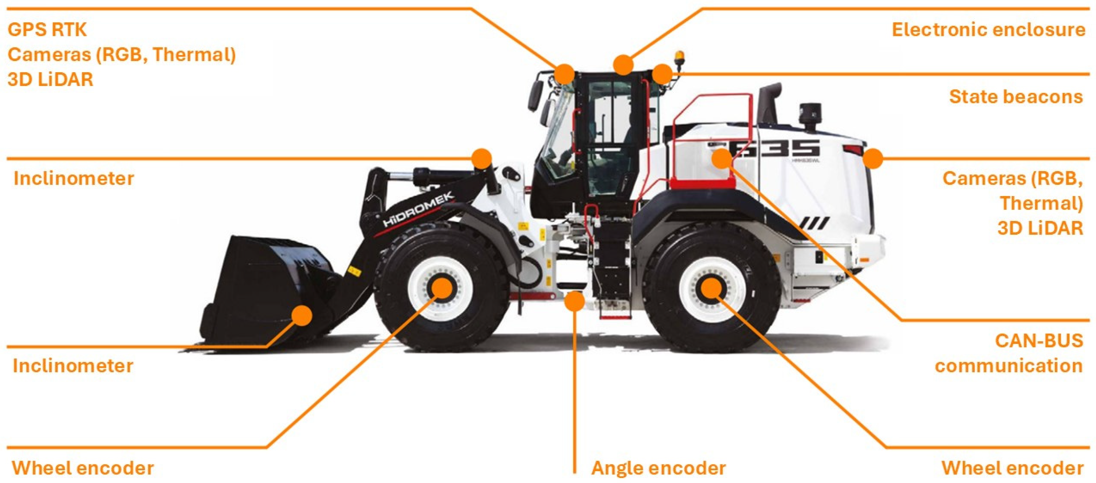
For the experimental validation, a commercial heavy-duty Wheel Loader utilizing a drive-by-wire architecture served as the automation platform. This configuration allows operational commands, including throttle, steering, and gear shifting, to be managed via CAN bus, providing a robust base for the integration of autonomous capabilities without requiring invasive mechanical modifications. Regarding perception, the platform is equipped with a comprehensive multi-modal sensor suite specifically designed to operate in the harsh, low-visibility conditions typical of post-blast tunnel environments. Specifically, the system comprises four 3D LiDAR sensors and a multi-camera RGB system providing a 360-degree field of view, as illustrated in Figure 3 and Figure S1. Furthermore, considering the potential presence of suspended dust or smoke, two radiometric thermal cameras have been integrated at the front and rear of the vehicle to enable effective perception beyond the visible spectrum. Additionally, a millimeter-wave radar provides perception redundancy, enhancing the reliability of obstacle detection in scenarios with extreme particulate matter. To ensure precise positioning and safety, a dual-antenna Real-Time Kinematic-Global Positioning System (RTK-GPS) provides centimeter-level positioning, while a dedicated safety radio control is included to allow operators to intervene swiftly from a safe distance acting as an independent hardware-based kill switch. All sensor data fusion and decision-making processes are handled by a ruggedized industrial PC installed in the cabin. Specific vehicle characteristics, engine details, and component placement are detailed in the Supplementary Information (Section S2).
Figure 3.
Sensors installed in the AWL.
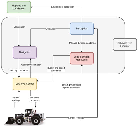
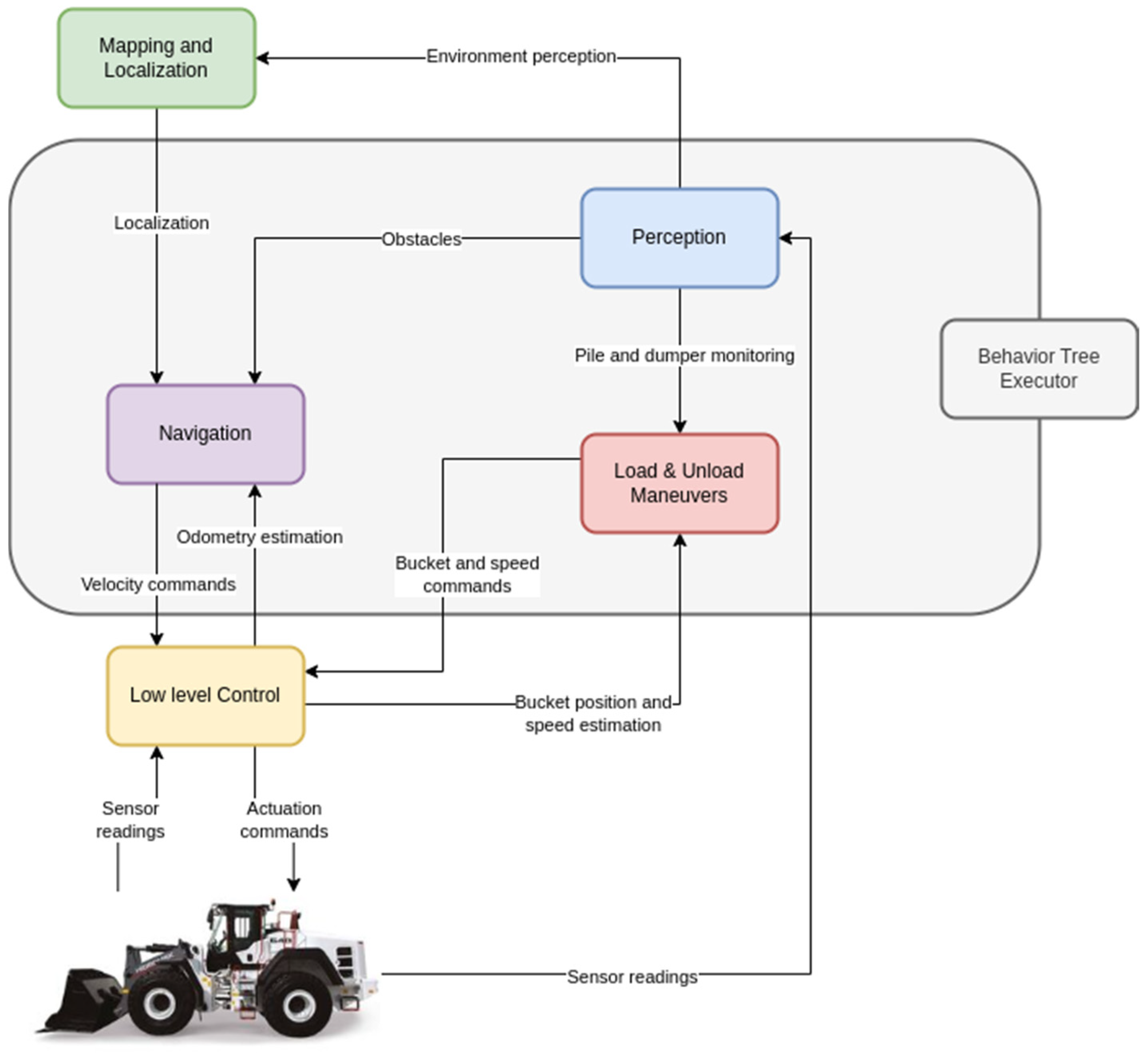
Regarding the control framework, the software architecture depicted in Figure 4 is built on ROS2 Humble and structured around a Behavior Tree (BT) framework that orchestrates high-level decision-making. In this context, the BT serves as the central control logic dynamically triggering perception, navigation and control routines according to the mission status. This modular approach facilitates flexible task sequencing and reliable mission execution, even under changing environmental conditions. Regarding mapping and localization, the system employs LG-SLAM [47], a graph-based framework that seamlessly integrates LiDAR, GNSS and IMU data. This approach is particularly advantageous as it incorporates a robust loop-closure mechanism ensuring global consistency and long-term map stability, even in large-scale or partially revisited environments. Moreover, to maintain accurate localization in GNSS-denied areas such as tunnels, G-LOC [48] is used. This framework maintains an active graph managed through a sliding-window approach; consequently, it allows the system to coherently fuse prior map information and its uncertainty while seamlessly handling transitions between outdoor (GNSS-available) and indoor (GNSS-denied) environments.
Figure 4.
Overview of the AWL’s software architecture.
Navigation capabilities rely on the NAV2 stack [49], which has been configured to address the non-holonomic constraints of the articulated vehicle. Specifically, feasible trajectories between navigation goals are computed by means of a Hybrid-A* global planner. This planner extends the traditional grid-based approach by considering motion primitives composed of straight and circular arc segments which comply with the robot’s kinematic constraints, such as the minimum turning radius. Subsequently, a Time Elastic Band (TEB) local planner [50] is employed to compute optimal control actions (linear velocity and steering angle of the articulation joint). The optimization problem considers the trajectory length, execution time, separation from obstacles and strict adherence to the vehicle’s dynamic and geometric constraints. To ensure smooth obstacle avoidance, a dynamic replanning node verifies the global path against the costmap in real-time; hence, if the path is obstructed by a dynamic object or a new environmental feature, a new trajectory is seamlessly computed and executed.
Regarding low-level control, the system leverages a calibrated cascade architecture to translate the trajectory references generated by the local planner into specific actuator commands. Ideally, this module must handle the non-linearities of the hydraulic steering and propulsion systems. The longitudinal control module computes the desired acceleration from the velocity error and applies calibration maps to translate this acceleration into specific throttle and brake values. Simultaneously, the lateral control regulates the articulation angle to ensure precise path tracking. Detailed explanations of the control laws, the block diagrams of the controllers and the kinematic model utilized are provided in the Supplementary Information (Section S3, Figures S2 and S3).
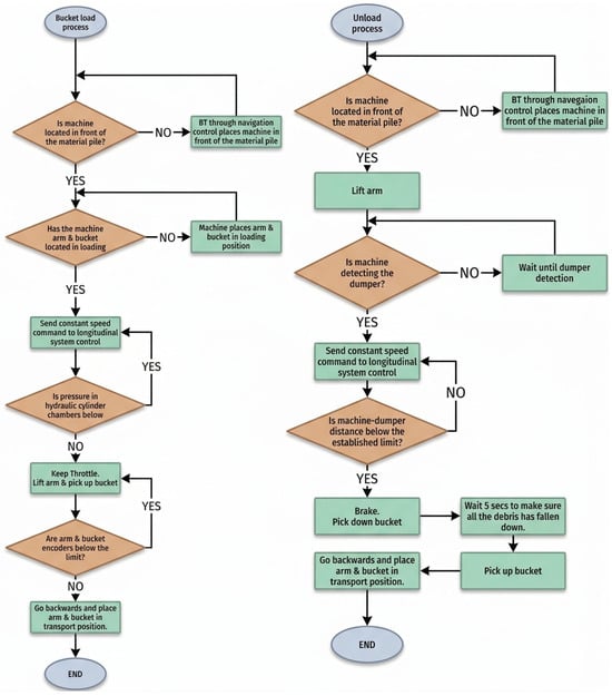
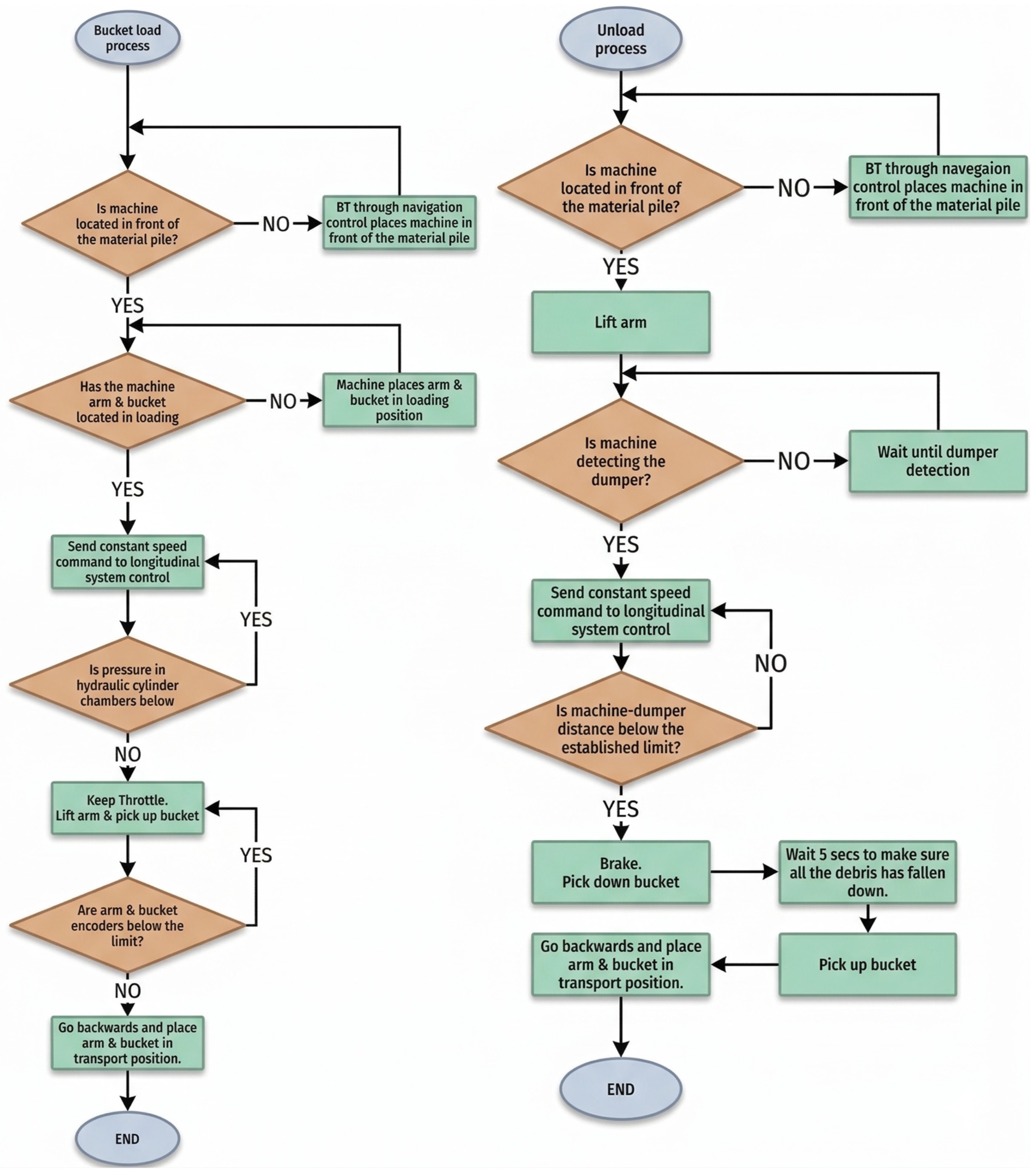
In relation to the autonomous operations, specifically the loading and unloading maneuvers, the approach presented in this work is based on a deterministic state machine architecture. In contrast to recent research relying on data-driven strategies such as deep reinforcement learning or imitation learning [51,52], this deterministic method offers higher interpretability, repeatability and robustness for critical earth-moving operations. As illustrated in Figure 5, the process is governed by a Finite State Machine (FSM) that transitions based on real-time feedback from hydraulic pressure sensors and encoders.
Figure 5.
Finite State Machine (FSM) diagram governing the autonomous loading operational logic.
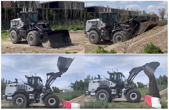
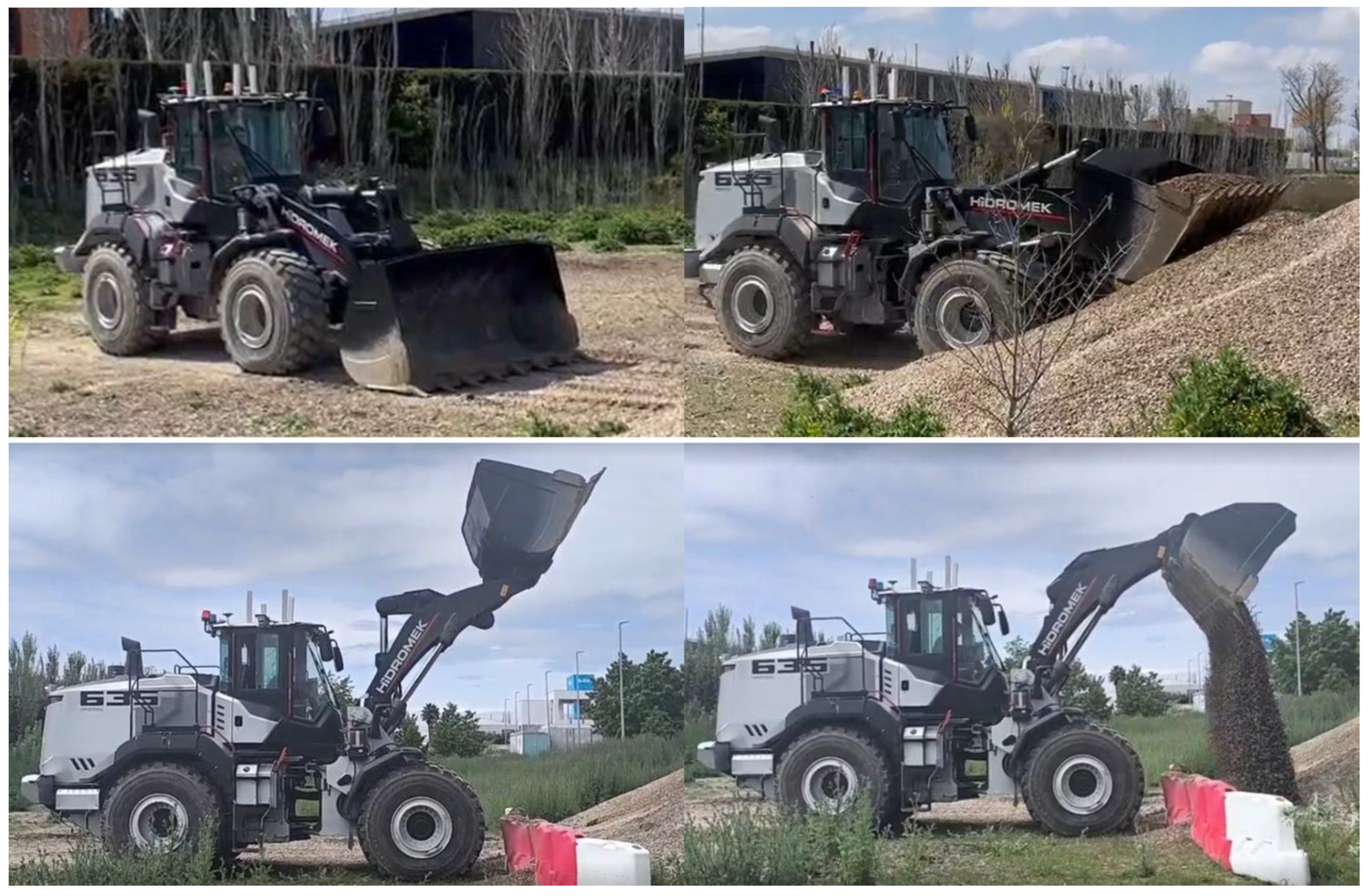
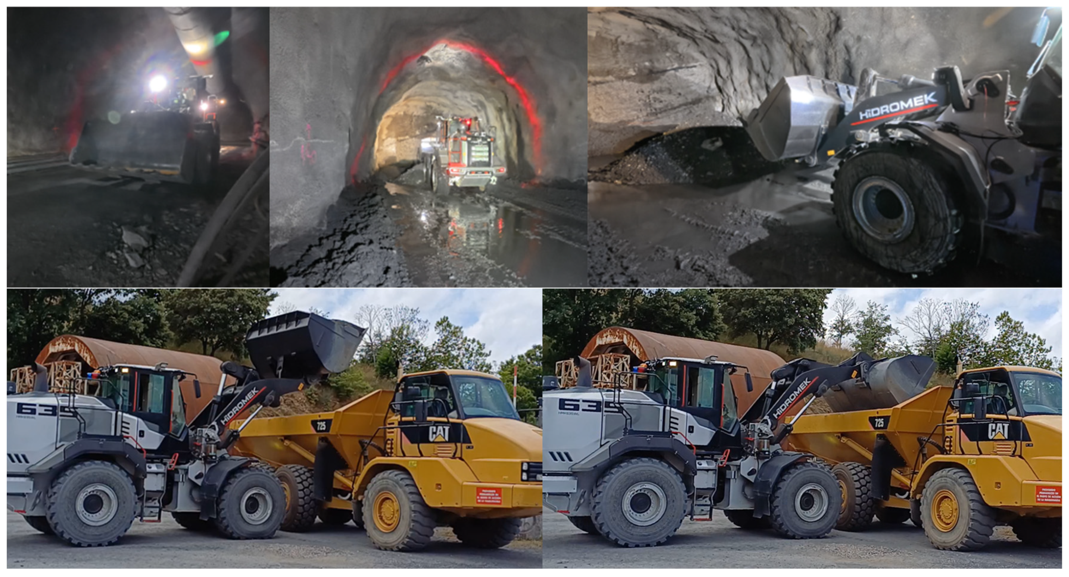
The autonomous loading process mimics the behaviour of an expert operator but optimized through sensor feedback, as visualized in the operational sequence of Figure 6. The machine positions the bucket parallel to the ground and advances towards the pile; then, upon detecting pile penetration via hydraulic pressure spikes in the lift cylinders, the system triggers a coordinated lifting and curling motion. This pressure-based trigger eliminates the need for complex visual estimation of the pile interaction, which can be unreliable in dusty conditions. Regarding the unloading process, the machine relies on the perception system to align with the dumper and discharge the material at a safe distance. Since the bucket lacks direct distance sensors, proximity is determined using data from the LiDAR and camera fusion system, ensuring that the machine stops automatically when the distance falls below a predefined safety threshold. Once positioned, the bucket is tilted forward to the limit of its piston stroke to discharge the material. A detailed step-by-step description of these sequences, including the specific pressure thresholds and mechanical movements, is available in the Supplementary Information (Section S4).
Figure 6.
Initial loading position and machine reached the pile at final loading position (top) and machine stopping in front of the objective and machine unloading process (bottom).
2.3. Digital Twin
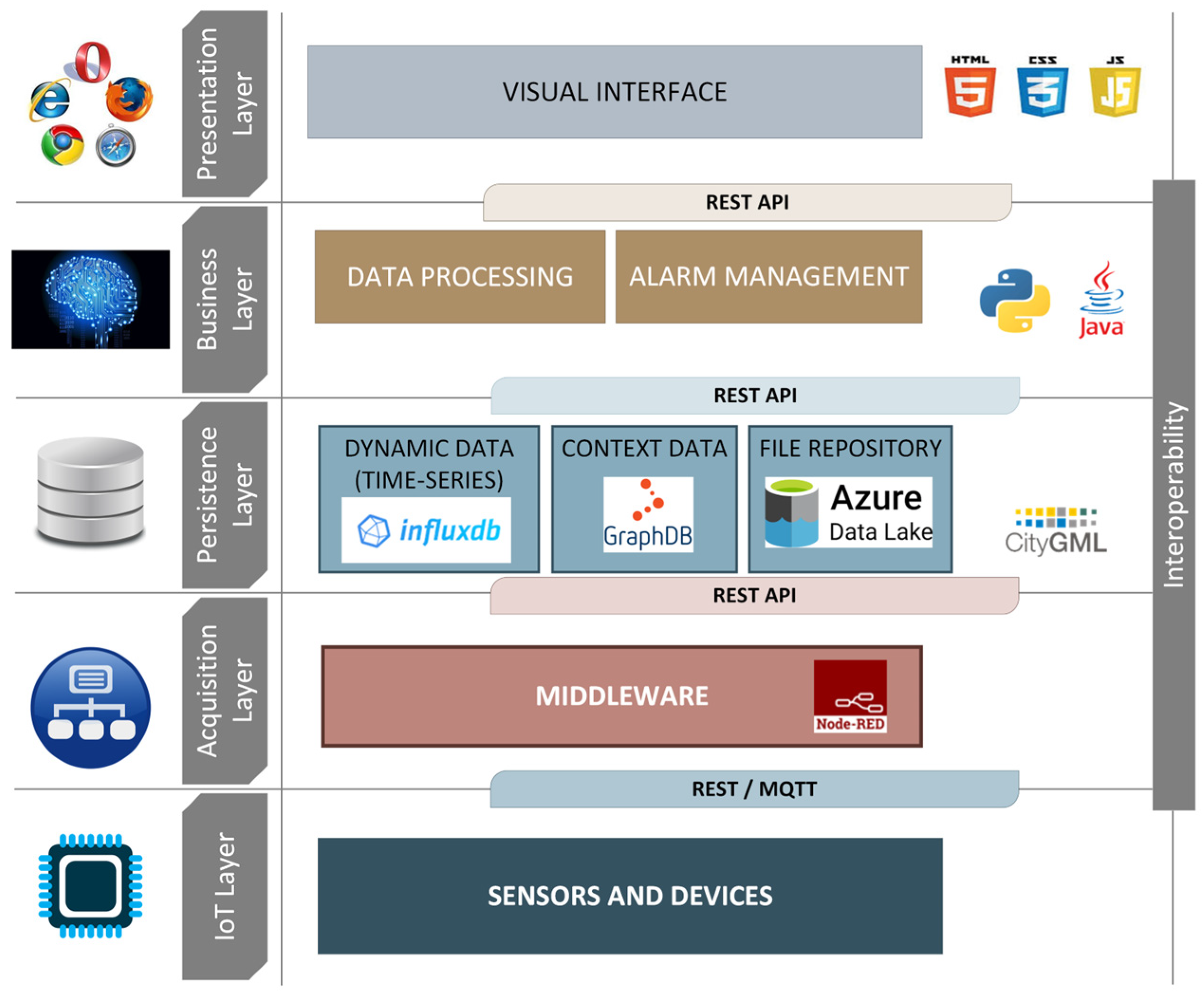
The design of suitable architectures for the orchestration and decision support of heterogeneous robotic agents in GNSS-denied environments is a challenge that requires moving beyond static modeling. Herein, the DT is presented not merely as a visualization tool. It acts as a central intelligence layer capable of orchestrating the UAV and AWL operations within a dynamic ecosystem that merges sensing, actuation, and analytics [35,36,37]. Specifically, the system leverages a hybrid cloud–edge architecture to integrate operational telemetry, unstructured data files, and static context information. This configuration guarantees low-latency responsiveness for safety-critical operations while ensuring scalability for long-term data processing [39,40]. Consequently, the data persistence layer combines a time-series database for high-frequency sensor readings with a triple store database that stores the semantic context via custom ontology. This structure adds a semantic layer to the raw data, facilitating complex queries for KPI computation and performance evaluation [38]. Regarding data accessibility, a RESTful API integrates these sources, making the information available for both the analysis modules and the user interface. The specific software stack, including the database technologies and visualization libraries utilized, is detailed in the Supplementary Information (Section S5).
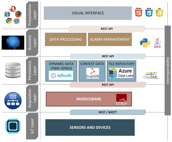
Furthermore, the DT orchestrates the coordination and data exchange between the autonomous aerial and ground platforms. However, a significant challenge arises from the interoperability between agents: the UAV operates on ROS1 while the AWL relies on ROS2. To overcome this limitation and ensure low-latency communication, the message queuing telemetry transport (MQTT) protocol was selected as the bridging middleware. Ideally, the UAV publishes LiDAR-based mapping data and positional updates to dedicated topics, while the AWL continuously streams motion telemetry and actuator states. The DT subscribes to all relevant channels, integrating these streams into a unified situational model as depicted in Figure 7. This architecture facilitates a closed-loop data flow where 3D maps generated by the UAV are processed and transmitted to the AWL to enable precise autonomous navigation.
Figure 7.
BEEYONDERS Digital Twin architecture.
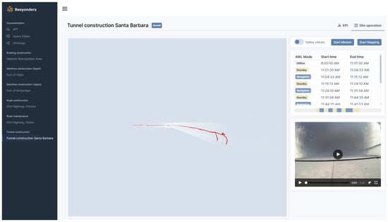
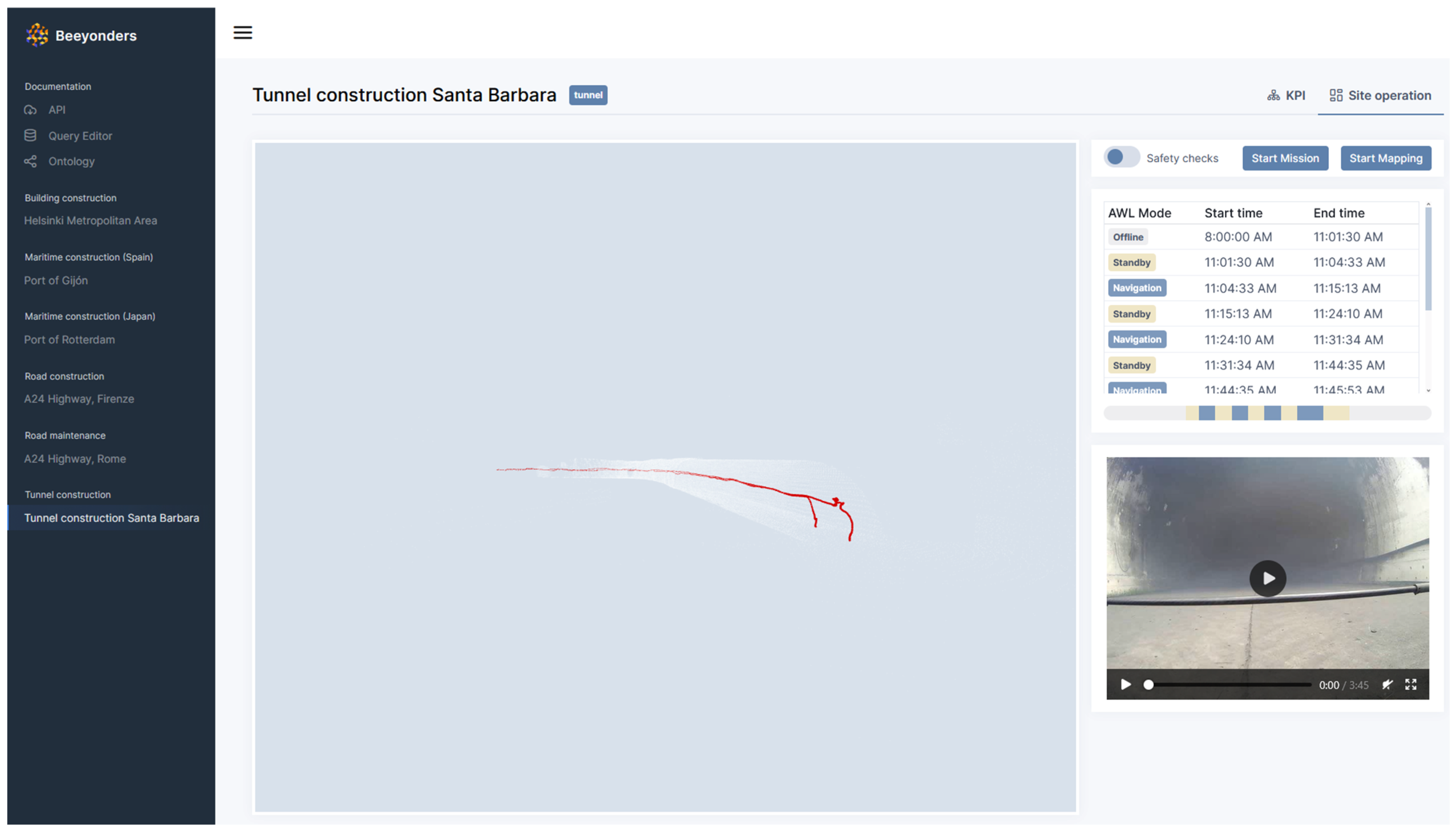
Within this context, decision-making follows a hierarchical model distributed across three levels to ensure robustness and safety. At the edge level (Internet of Things (IoT) layer), robotic agents perform low-level autonomy based on local sensor fusion. At the coordination level (Business layer), the DT monitors mission states and enforces temporal constraints; for instance, it triggers the AWL’s entry sequence only after the UAV completes the mapping of the excavation front. Finally, at the supervisory level (Presentation layer), high-level planning is derived from DT analytics and human-in-the-loop control. The resulting interface, illustrated in Figure 8, allows operators to visualize mission progress and override commands if necessary. In short, this multi-layered control paradigm establishes a cyber–physical feedback loop where sensor data provides the system state on which digital decisions are based that are subsequently executed as control actions in the real environment [37,38]. Although the current implementation focuses on sequential operations, this architecture is designed to support future expansion towards distributed scheduling and conflict-avoidance algorithms for simultaneous multi-robot missions [34,53].
Figure 8.
Tunnel monitoring interface.
2.4. Experimental Setup and Validation Scenario
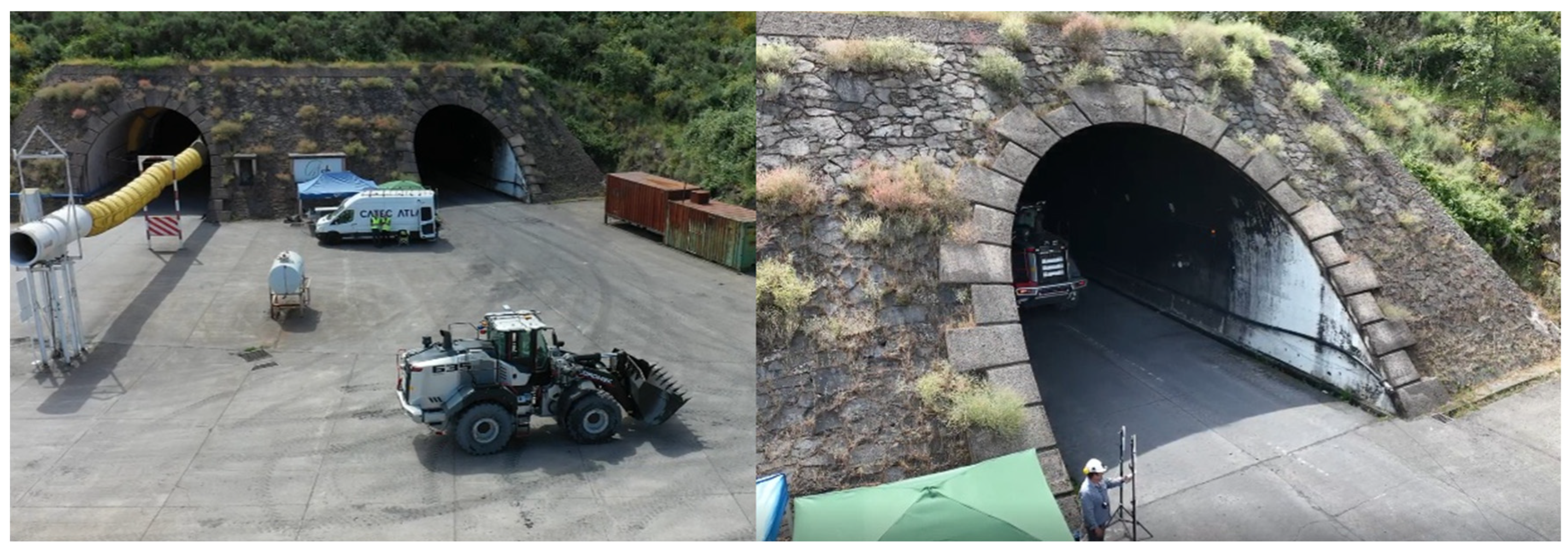
Herein, the experimental validation was conducted at the Santa Bárbara Foundation (SBF) in León, Spain. This facility, specifically designed for subterranean research, features a 500 m tunnel characterized by confined cross-sections, covering an area of approximately 50 m2, with an equivalent diameter that narrows from roughly 8 m at the entrance to between 5 and 7 m in deeper sections, and the complete absence of GNSS signals (Figure 9). Consequently, it provides a representative benchmark for evaluating robotic autonomy under realistic denial-of-service conditions.
Figure 9.
Overview of the use case location showing the exterior area and tunnel access in SBF.
To address the operational downtime associated with the mandatory post-blast ventilation periods described in Section 1, the validation scenario was designed to simulate the immediate aftermath of a detonation. Since ensuring experimental repeatability and safety precluded the use of live explosives during the robotic trials, a controlled particulate generation system was employed. Specifically, this equipment generated a dense aerosol cloud capable of reducing optical visibility to critical levels, thereby effectively emulating the suspended dust and toxic gases typical of a blast event. While the structural and lighting conditions of the tunnel remained identical across all trials conducted during the same week, the density of the simulated smoke was intentionally varied to fine-tune and validate the robustness of the perception algorithms under different levels of visibility degradation. The setup and validation of this simulation system are depicted in Figures S4 and S5 of the Supplementary Information, while the technical specifications of the equipment are detailed in Section S6.
Regarding the supporting infrastructure, specific adaptations were required to counteract the environmental hostility. Ideally, SLAM algorithms rely on natural features; nevertheless, the tunnel walls at SBF are coated in soot from prior fire tests, exhibiting low reflectivity that compromises standard LiDAR odometry. To overcome this limitation, a sparse array of reflective markers was deployed along the initial section to provide stable radiometric features for localization, as illustrated in Figure S6. Furthermore, to guarantee continuous telemetry and video streaming, a temporary mesh network was distributed along the tunnel (Figures S7 and S8). To prevent bandwidth degradation in the multi-hop topology, the proximal nodes were interconnected via Ethernet backhaul and powered by independent battery systems, the details of which are provided in Supplementary Information (Section S7).
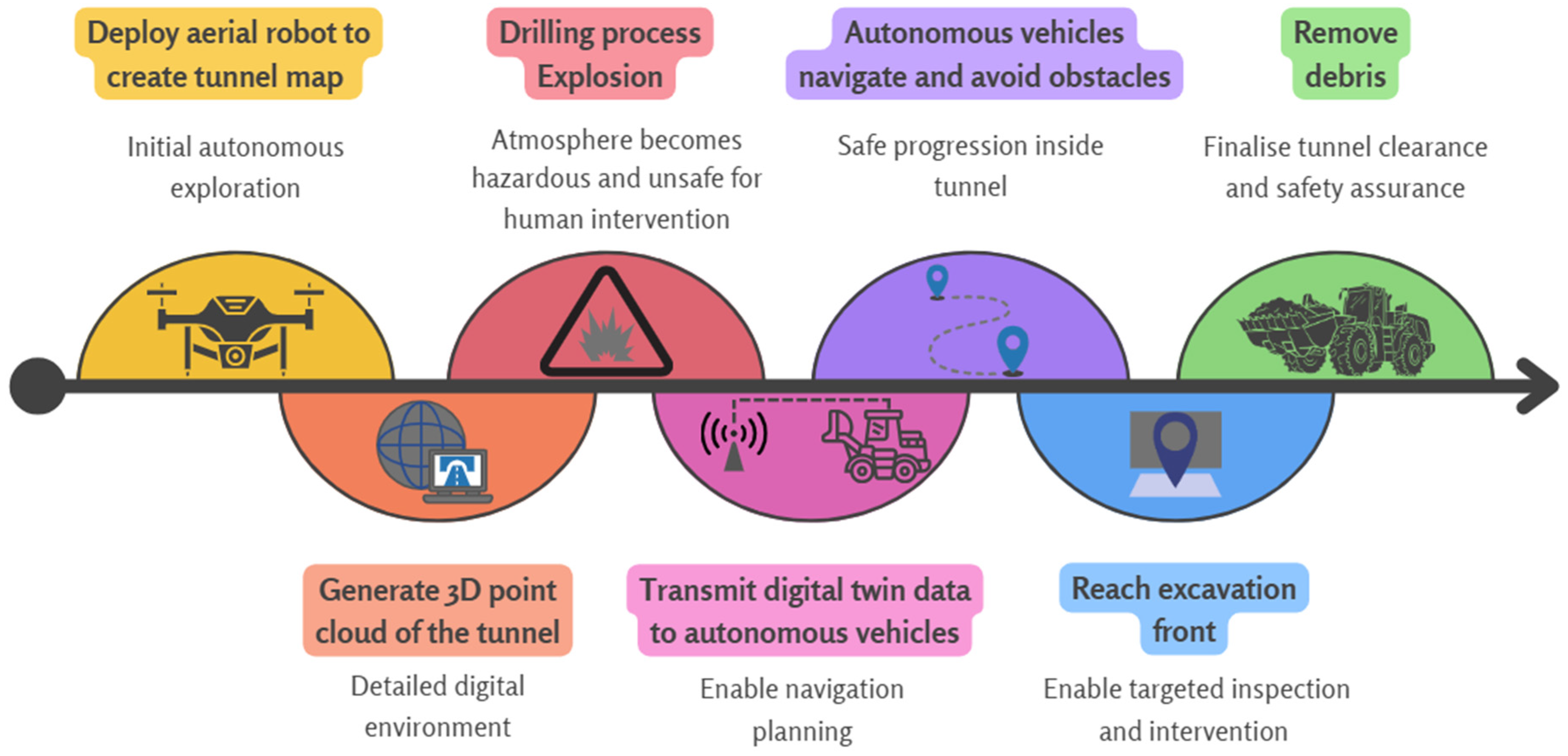
To overcome the operational bottleneck imposed by the mandatory ventilation periods, an integrated autonomous workflow was defined by a team of end users who were experts in construction, together with technology developers, and orchestrated by the Digital Twin, as visually summarized in Figure 10. Specifically, the methodology replaces the idle waiting time with an immediate robotic intervention sequence. Herein, the UAV acts as an autonomous scout, entering the hazardous post-blast environment to generate a real-time occupancy map using the dust-filtering capabilities described in Section 2.1. Instead of a strictly sequential handover, the system enables a cooperative advancement: the aerial agent streams the updated map and its position to the Autonomous Wheel Loader (AWL) via the low-latency MQTT bridge. Consequently, the AWL can enter the tunnel in a tandem formation, utilizing the UAV as a dynamic navigational beacon to progress safely through low-visibility zones towards the excavation front. Once the debris pile is reached, the UAV hovers in a safe position while the AWL executes the autonomous loading and transport cycle. A detailed breakdown of each operational phase, including specific decision triggers and data exchange events, is provided in the Supplementary Information (Section S8).
Figure 10.
Sequential process of autonomous tunnel inspection and intervention.
3. Results
3.1. UAV Performance and 3D Mapping
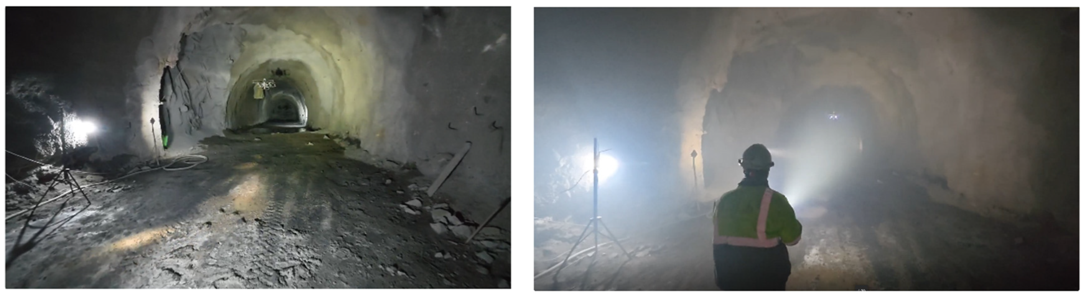
In this subsection, the aerial robotic performance is evaluated under two distinct environmental scenarios to validate the system’s adaptability: the pre-detonation phase (clear atmosphere) and the post-detonation phase (degraded visibility). As visually contrasted in Figure 11, these varying visibility conditions impose radically different requirements on the perception stack, necessitating a robust sensor fusion strategy.
Figure 11.
Tunnel excavation front with two different visibility conditions ((Left) Before detonation; (Right) After detonation).
3.1.1. Pre-Detonation Phase: Baseline Geometrical Reconstruction
The primary objective of this phase was to establish a high-fidelity 3D map of the tunnel to serve as the ground truth for navigation. To this end, the autonomous exploration module guided the UAV from the tunnel entrance to the excavation front, utilizing the localization framework initialized by the reflective markers described in Section 2.4 (Figures S9 and S10). The mission was executed with a maximum cruise speed of 1.5 m/s, allowing the platform to cover the trajectory and complete the scanning process in approximately 310 s. Subsequently, the return-to-home (RTH) maneuver was completed in 170 s, resulting in a total flight mission time of 8 min (480 s). Additional flight dynamics, including the return logic and battery performance profiles, are detailed in the Supplementary Information (Section S9, Figure S11).
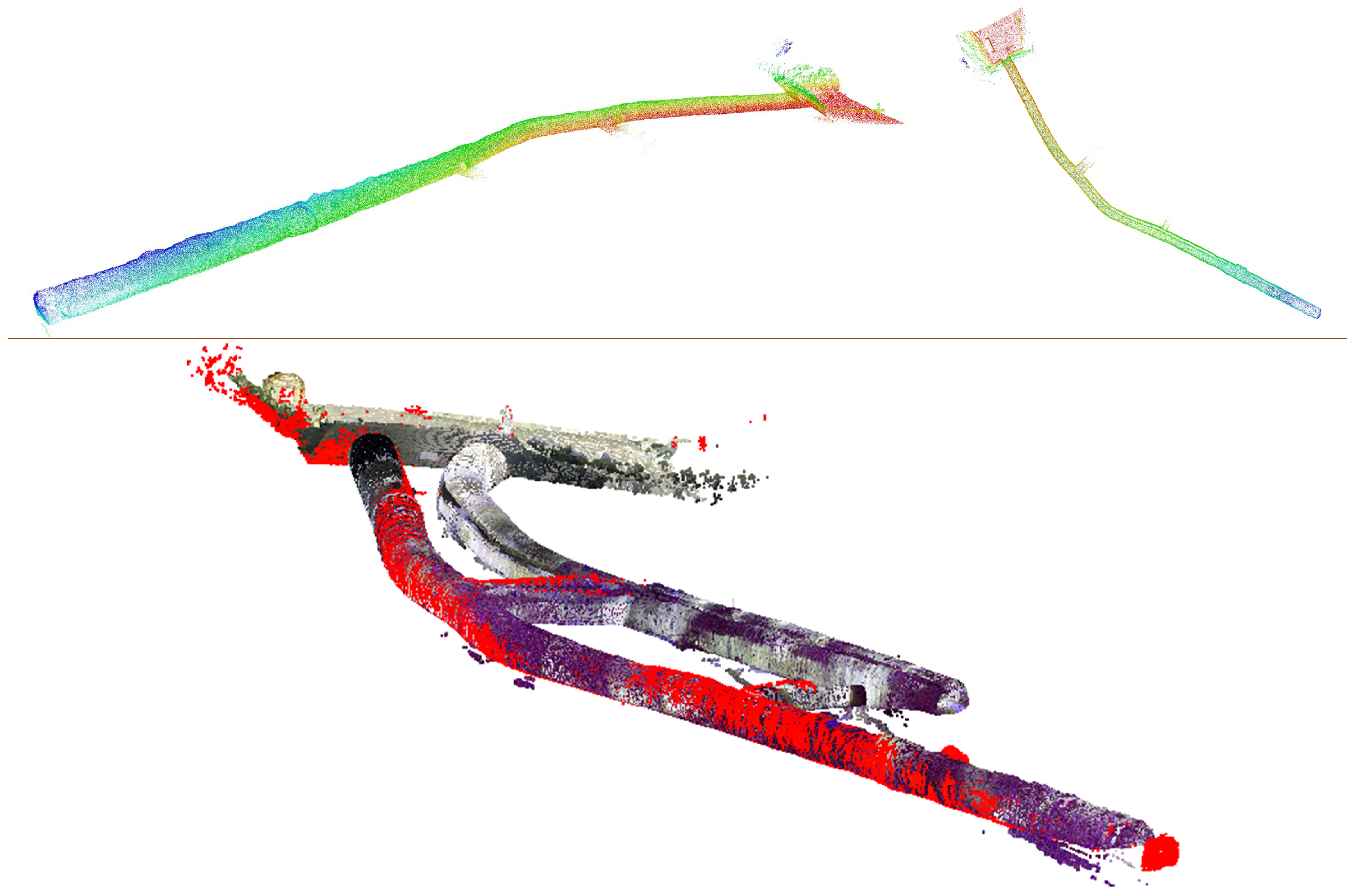
Notably, the system generated a dense point cloud of the complete tunnel geometry in real-time. To quantify the reconstruction accuracy, this map was compared against a ground truth model generated via a LEICA Total Station, a process that originally required several days of manual surveying. The comparison was performed using a Cloud-to-Cloud (C2C) distance computation, which calculates, for each point in the UAV-generated map, the distance to its nearest neighbour in the reference cloud, providing a spatially distributed assessment of geometric fidelity across the full tunnel geometry. As evidenced in Figure 12, the alignment between the UAV-generated map (completed in roughly 8 min) and the topographical standard is geometrically consistent. The overlay of both point clouds reveals a high degree of congruence in the structural features of the tunnel walls and the excavation front, with a mean distance between a mean C2C distance of 0.39 m with a standard deviation of 0.94 m. Therefore, the proposed architecture demonstrates that autonomous aerial scanning can replace traditional topography for rapid progress monitoring, drastically reducing data acquisition time without compromising geometric precision.
Figure 12.
Resulting 3D map after the operation before detonation, shown as side view (Top left) and top view (Top right), where colour represents elevation from red at the lowest point to blue at the highest. The bottom image shows a comparison between the ACCIONA total station point cloud, displayed with RGB colour information, and the UAV-generated point cloud, displayed in uniform red as only XYZ coordinate data is available.
3.1.2. Post-Detonation Phase: Navigation in Degraded Visibility
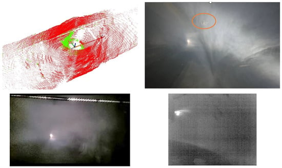
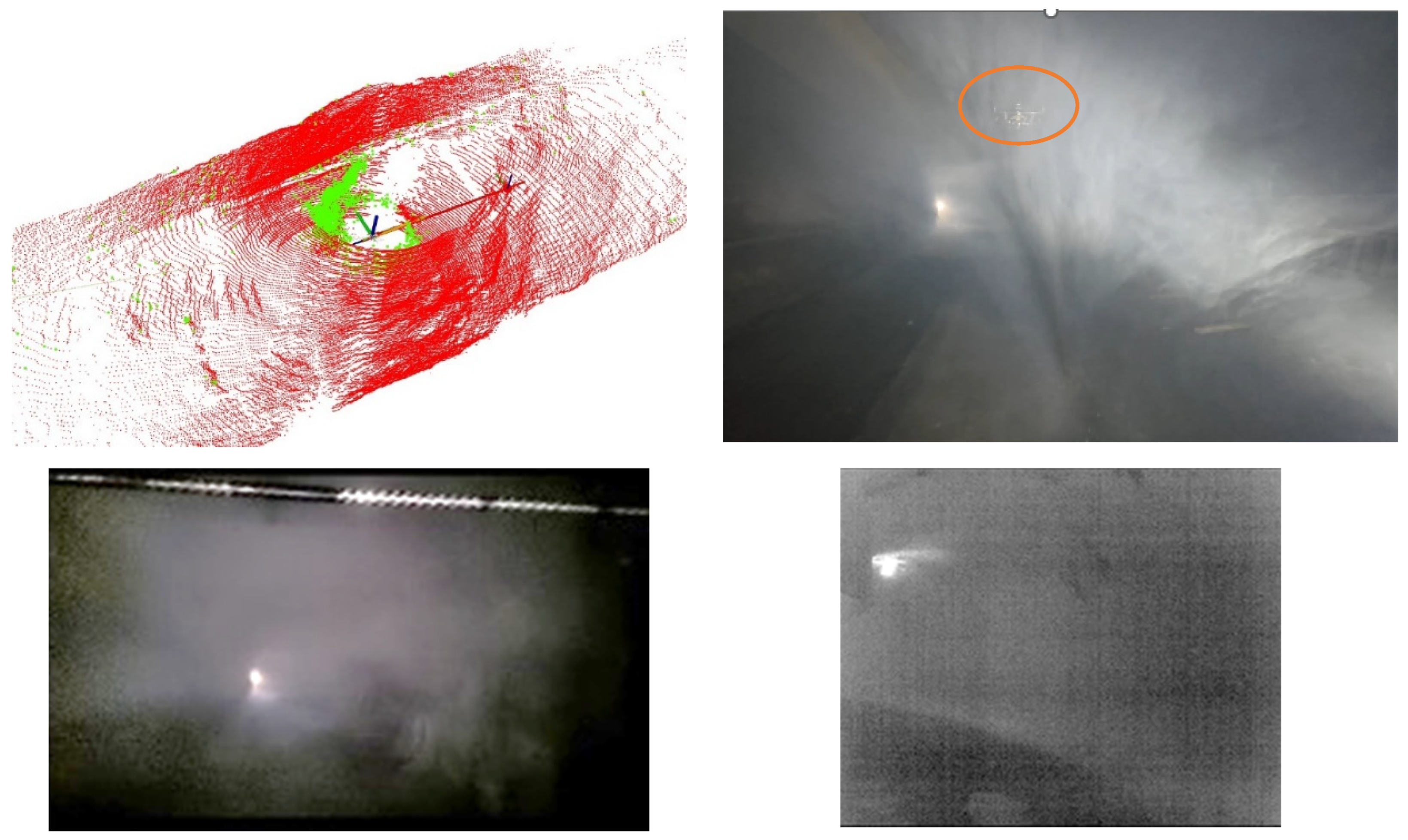
Following the controlled simulation of the blast, the UAV was deployed into the dust-laden environment to validate the robustness of the perception stack. Under these circumstances, standard optical sensors are rendered ineffective; as shown in Figure 13, the RGB camera feed is completely saturated by the opaque fog, providing zero situational awareness. Nevertheless, the sensor fusion strategy successfully overcame this limitation.
Figure 13.
(Top) LiDAR 3D point cloud (filtered points in red and dusty points in green colour) and UAV recorded from outside, marked with an orange circle; (Bottom Left) RGB image (Bottom Right) Thermal Camera.
Specifically, the thermal imaging system penetrated the suspended particulates, revealing the tunnel structure and potential heat signatures hidden from the visible spectrum. Simultaneously, the intensity-based filtering algorithms described in Section 2.1 effectively removed the noise artifacts generated by the airborne dust from the LiDAR scan. The comparison between the raw noisy data and the filtered point cloud is depicted in Figure 13 (top). This real-time cleaning process allowed the SLAM system to maintain a stable pose estimation despite the environmental clutter. Consequently, the UAV was able to navigate safely to the excavation front and transmit a clean occupancy map to the Digital Twin, ensuring the subsequent entry of the ground machinery.
3.2. AWL Performance and Ground Operations
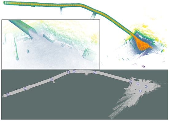
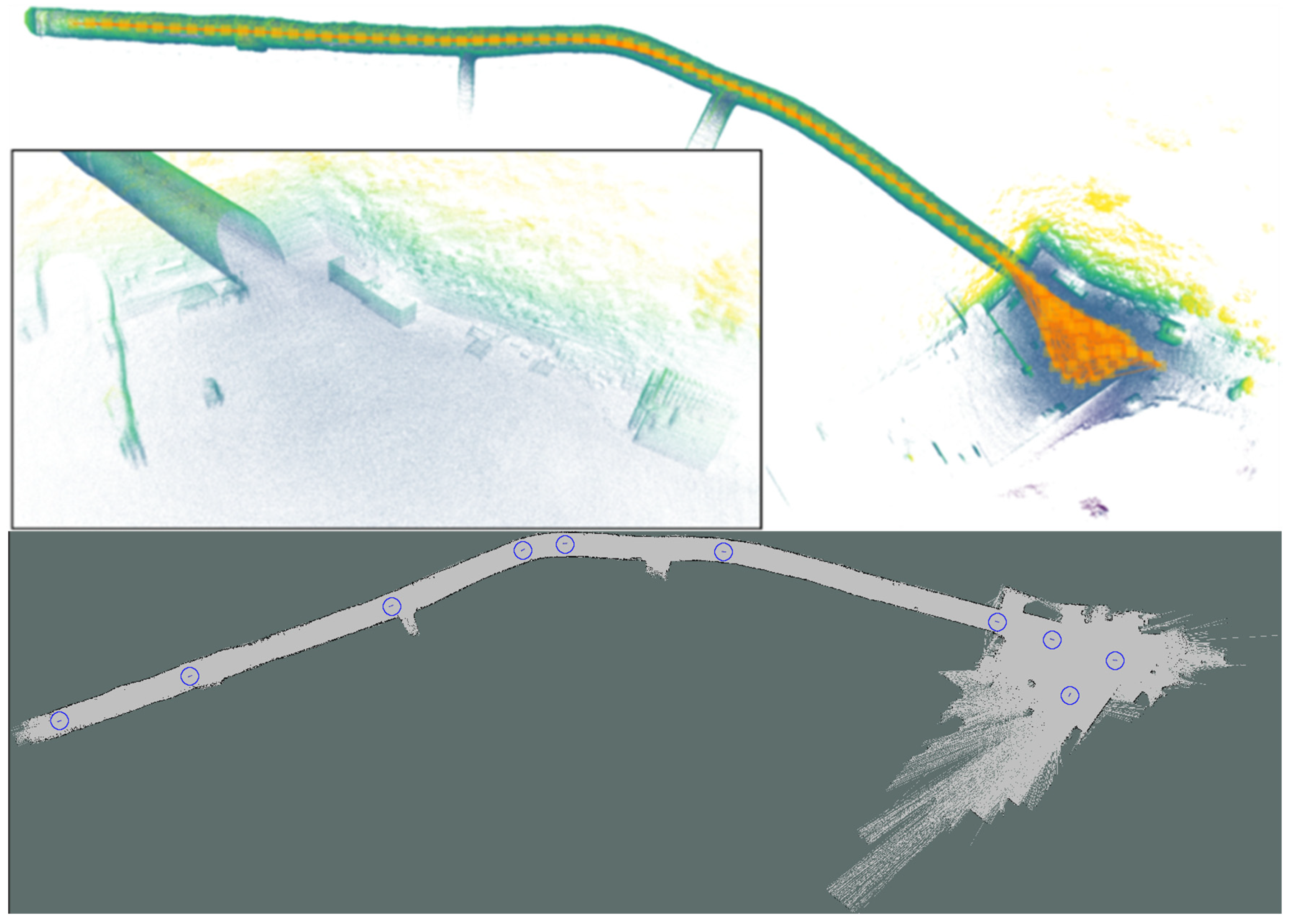
To assess the feasibility of unmanned heavy-duty interventions, the experimental validation focused on the AWL’s ability to enter and operate within the tunnel entirely without human presence. Specifically, the navigation framework was validated using the 3D map previously generated by the aerial platform, which served as the sole guidance reference for the machine. This map was converted into a 2D occupancy grid to define the allowable drivable surface and, as illustrated in Figure 14, a set of navigation waypoints was defined to guide the Autonomous Wheel Loader (AWL) safely from the exterior staging area to the excavation front.
Figure 14.
Ground navigation setup: (Top) 3D map reconstruction of the tunnel environment, represented as a colored point cloud, including the pose graph (orange); (Bottom) 2D occupancy grid and defined waypoints (marked by blue circles) for the bidirectional trajectory.
It is worth noting that, due to the confined dimensions of the tunnel relative to the machine’s size, performing U-turns inside the gallery was geometrically impossible. To overcome this physical constraint, the navigation logic was adapted to execute a bidirectional strategy: the AWL approached the excavation front in forward gear and exited the tunnel in reverse gear, utilizing the same set of waypoints for both trajectories. The path planning algorithms successfully managed these non-holonomic constraints, maintaining the vehicle centered within the safety margins throughout the 500 m traverse. Due to the inability to perform maneuvering inside the tunnel, the environment was kept free of obstacles to ensure safe operation. Visualizations of the computed local trajectories and the dynamic path planning interactions are provided in the Supplementary Information (Section S10, Figures S12 and S13).
Upon reaching the excavation front, the system triggered the autonomous loading maneuver. The effectiveness of this operation is depicted in Figure 15 (top), where the machine successfully engaged the debris pile and filled the bucket without human intervention. The control architecture described in Section 2.2 proved robust against the irregularity of the terrain, managing the hydraulic pressure spikes to execute the curling motion at the optimal penetration point. To ensure reproducibility, specific pressure thresholds were set at 100 bar for the boom cylinder, 50 bar for the bucket cylinder, and 140 bar for the combined system, adjusted during calibration based on the pile’s material and consistency. Subsequently, the machine transported the load to the exterior dumping area. The perception system correctly identified the dumper truck, aligning the AWL to discharge the material at a safe distance as shown in Figure 15 (bottom). The stopping distance for dumping is another critical parameter. It was calibrated to 1.20 m; however, due to vehicle dynamics and sensor-to-software latency, the final real-world gap is slightly shorter to ensure accurate material discharge and avoid collisions. This cycle confirms that the proposed architecture effectively bridges the gap between digital planning and heavy-duty physical actuation in unstructured environments.
Figure 15.
Validation of autonomous earth-moving operations: Material loading sequence at the excavation front (top) and precision discharge into the dumper truck in the exterior staging area (bottom).
3.3. Integrated Air-Ground Workflow and Digital Twin Coordination
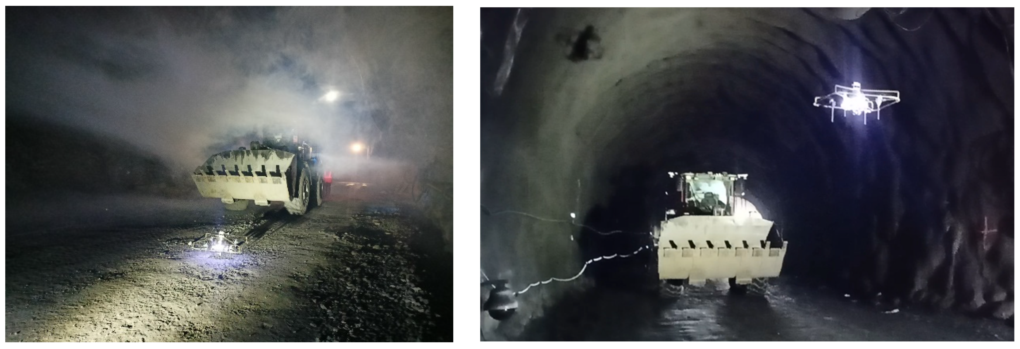
The collaborative capabilities of the heterogeneous robotic fleet were validated in this real-world tunnel environment. Figure 16 illustrates the simultaneous operation of the aerial platform and the ground machinery within the tunnel. Utilizing the ROS2 communication protocol defined in the Supplementary Information (Section S11, Figure S14), a stable data link was successfully established, overcoming the interoperability constraints between the agents without compromising the real-time performance required for the operation.
Figure 16.
Aerial Robot and Autonomous Wheel Loader working together inside of the tunnel.
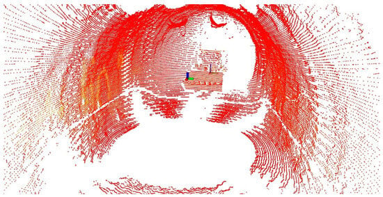
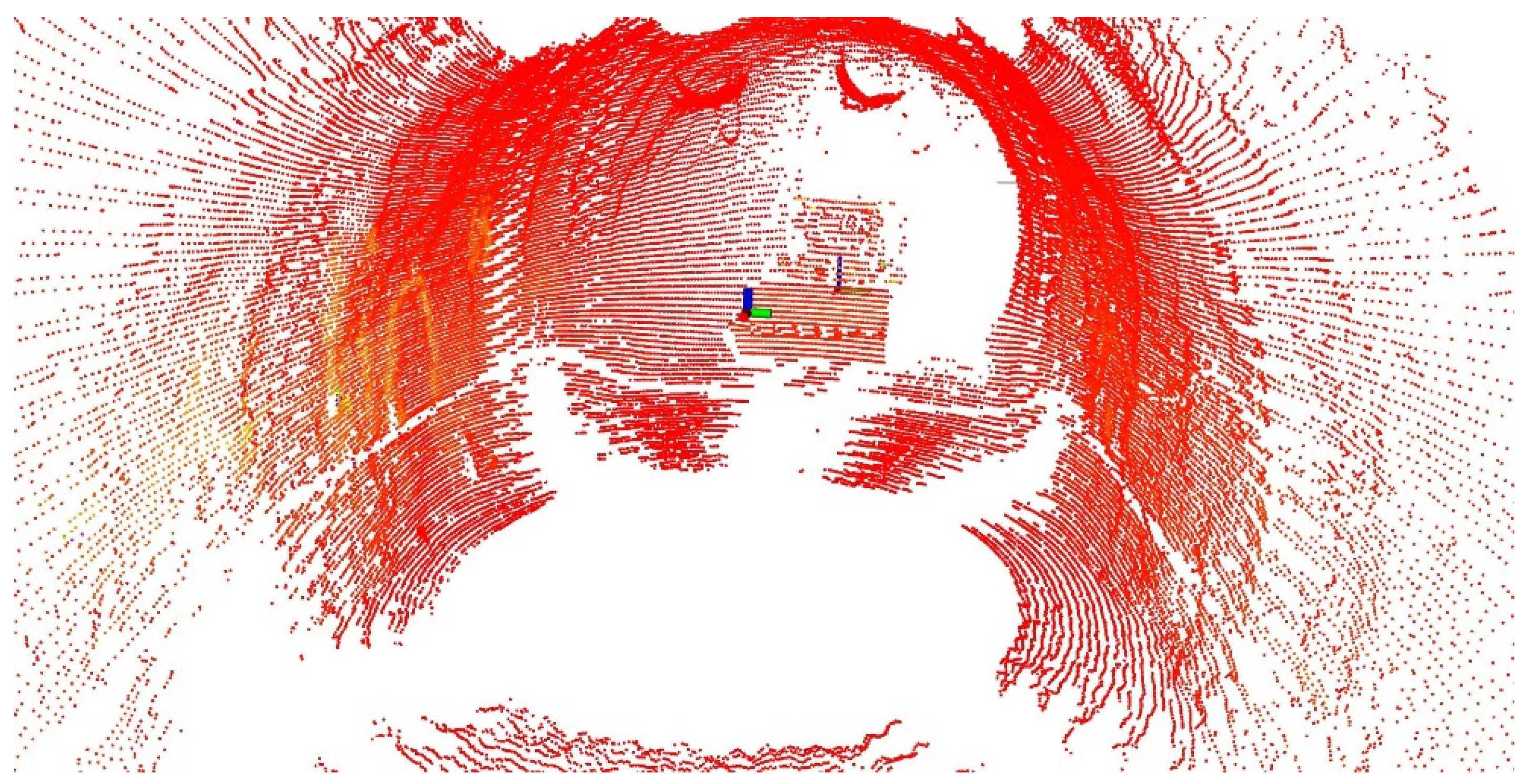
The robustness of the shared localization framework was confirmed through the analysis of the collected sensor data. As evidenced in the LiDAR scan visualization (Figure 17), the UAV perception system was able to reliably detect and track the AWL within the confined environment. Both the aerial and ground agents were successfully referenced in a common coordinate system, validating the spatial synchronization essential for DT integration. Specifically, both systems operate within a common reference frame enabled by the graph-based mapping and localization framework. The AWL localizes using G-LOC on top of the UAV-generated maps, while the UAV pose is expressed in the same consistent global frame before being transmitted. Furthermore, regarding end-to-end operation, the system runs in a perception–localization–control loop driven by the LiDAR update rate (10 Hz), which defines the main update frequency for state estimation and trajectory adaptation in the AWL.
Figure 17.
AWL inside the aerial robot 3D LiDAR scan, where the point cloud is displayed in red. The small and large axes represent the UAV and AWL poses, respectively, with respect to a common reference frame, following the standard axis colour convention (X = red, Y = green, Z = blue).
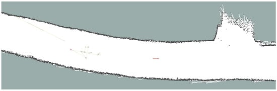
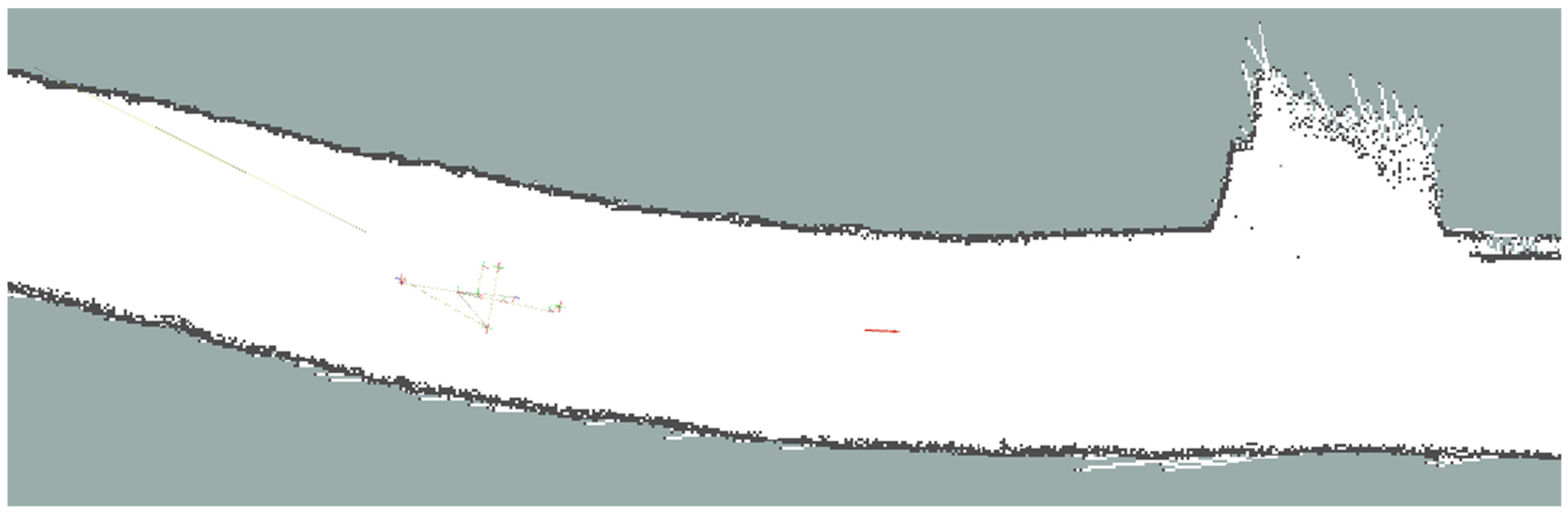
Furthermore, the feasibility of the “scout” operational mode was demonstrated. The high-frequency exchange of pose messages allowed the integration of the UAV’s real-time position into the AWL’s navigation stack. Figure 18 depicts this integration, where the UAV’s streamed coordinates are projected as dynamic navigation goals on the AWL’s local costmap. This result confirms the capability of the aerial agent to effectively guide the heavy machinery towards the excavation front in low-visibility conditions, replacing static waypoints with a dynamic leader–follower scheme.
Figure 18.
Representation of the UAV’s position (red arrow at the center) on the AWL navigation map.
4. Discussion
4.1. Comparative Analysis and Lessons Learned
The experimental results obtained from the demonstrator represent a significant advance over current construction operations in post-blast tunnel excavation. While previous works have largely focused on isolated subsystems, such as UAV-based inspection, ground robotics or digital supervision [54,55], the proposed architecture successfully integrates these technological domains into a unified workflow. This integration addresses the operational bottleneck identified in the introduction by transforming the conventional sequential approach, inspection followed by hauling, into a continuous and collaborative process. By deploying the UAV immediately after the event to generate environmental data, the system enables early robotic intervention without exposing personnel to hazardous conditions. This capability extends recent advances in robotic exploration for underground environments [56] by introducing a cooperative framework where the aerial agent dynamically informs the navigation of the heavy machinery.
From a methodological perspective, the experiment validates the role of the DT as an active orchestrator rather than a passive monitoring tool. Unlike previous Digital Twin applications in tunnelling primarily limited to visualization or post-operations [36], the framework herein proposed integrates real-time telemetry and point-cloud data to enable live supervision and task synchronization. Furthermore, the implementation of a hybrid cloud–edge architecture with semantic ontologies ensured the scalability required for real-time data exchange in complex construction scenarios.
Regarding the autonomous ground operations, the Finite State Machine (FSM) implemented on the heavy machinery successfully reproduced expert operator behavior. The system effectively leveraged pressure sensors and encoder feedback to manage pile penetration and loading cycles, demonstrating robustness against the irregularity of the terrain. Nevertheless, specific constraints were identified during the validation that limit the scalability of the current setup. Regarding communication, the deployed linear mesh topology implies that each additional wireless hop theoretically reduces the available bandwidth by approximately half. Although proximal nodes were interconnected via Ethernet backhaul to mitigate this progressive attenuation, the observed signal degradation over long distances motivates the adoption of industrial-grade private networks such as 5G in future deployments. Similarly, regarding UAV endurance, the aerial platform completed the 8 min mission within the safety margins of a single battery cycle, which has a theoretical maximum flight time of approximately 14 min. However, this figure can vary in practice due to airflow conditions within the tunnel, such as ventilation currents, which increase motor load. Consequently, scaling the system to longer tunnel distances will require higher energy density batteries or intermediate recharging strategies, along with adaptive return-to-home logic based on real-time energy consumption.
From a critical standpoint, the experimental validation strategy proved effective for Technology Readiness Level (TRL) 6 evaluation, although specific simplifying assumptions were required. It is acknowledged that the validation was conducted using artificial aerosols. While this setup effectively replicates the visual occlusion, light scattering, and attenuation effects critical for optical and LiDAR sensors, it does not simulate the high thermal gradients or overpressure waves present in a live blast. In a real detonation, extreme temperature variations can induce localized changes in the refractive index of the air, potentially affecting laser propagation accuracy. Consequently, while the current fusion algorithms successfully handle particulate occlusion, future pilot tests in active tunnels will focus on validating the sensor housing resilience and data calibration stability against these specific thermodynamic phenomena.
4.2. End-User Evaluation and Practical Applicability
The practical viability of the proposed autonomous architecture was evaluated considering three core dimensions: operational efficiency, data reliability and human factors. Table 1 summarizes the qualitative and quantitative impact of the system compared to conventional manual procedures.
Table 1.
Comparative analysis between Conventional Procedure and the Proposed Autonomous System.
Regarding operational efficiency and economic impact, the system addressed the downtime caused by post-blast ventilation protocols. The autonomous deployment enabled operations to commence 50% to 80% earlier than the conventional procedure, depending on the tunnel section executed. Consequently, it is estimated that the technology reduces the daily operational time by approximately 5% to 10% (with a representative value of 8%). These efficiency gains translate directly into workforce optimization. Although the initial investment for the experimental system is estimated at approximately twice the cost of a standard Wheel Loader, the return on investment (ROI) calculation suggests a payback period ranging from one to seven months, contingent on the tunnel’s cross-sectional area and total length.
From a safety and quality perspective, the autonomous workflow eliminated 100% of human exposure during the critical inspection phase, mitigating risks associated with structural instability and unexploded charges [57]. Simultaneously, the transition from manual observation to automated data capture improved the reliability of automated progress control. The generation of georeferenced point clouds after each blast provided an objective “as-built” record, overcoming the subjectivity and variability inherent in traditional inspections. This aligns with recent findings [58,59], confirming that automated spatial acquisition enhances construction quality assurance and regulatory compliance through digital traceability.
Finally, regarding human–machine interaction and usability, the system demonstrated a Technology Readiness Level (TRL) of 6. While specific control interfaces for non-expert personnel require further integration, the Human–Machine Interface (HMI) proved effective for real-time supervision. Observations during the field trials indicate that worker acceptance is strongly correlated with the perception of safety and the system’s ability to operate without obstructing human tasks. This supports previous studies [60,61,62], which emphasize that successful adoption of robotic construction technologies depends on perceived reliability and respect for the human workspace. Further details regarding the specific training protocols and the deployment timeline are provided in the Supplementary Information (Section S12).
Overall, the practical applicability of the system extends beyond immediate on-site metrics. The transition from manual inspections to the systematic generation of digital ‘as-built’ records facilitate evidence-based decision-making at the organizational level. By centralizing geometric and operational data within a unified environment, the proposed architecture converts the post-blast phase from a fragmented task into a measurable industrial process, supporting the digitalization of underground construction.
5. Conclusions
The current study reports on the validation of an integrated cyber–physical architecture for the automation of post-blast tunnel operations. The systematic experimental characterization in a GNSS-denied environment confirmed that the coordination between aerial and ground agents via a Digital Twin is a feasible strategy to overcome the current bottleneck of manual inspections.
Regarding aerial performance, the UAV successfully executed autonomous exploration under degraded visibility conditions. The system generated high-fidelity 3D maps in less than 8 min, providing geometric precision comparable to total station measurements. Consequently, the shared localization framework allowed the Autonomous Wheel Loader (AWL) to navigate and perform mucking operations without human intervention, validating the robustness of the proposed sensor fusion strategy against environmental clutter. By decoupling the inspection phase from physical human entry, the system ensures a higher safety standard while maintaining data integrity.
From another point of view, the coordinated workflow demonstrated a clear impact on efficiency. The autonomous deployment enabled the start of operations 50% to 80% earlier than standard procedures, effectively converting mandatory ventilation downtime into productive time. This efficiency gain translates to an estimated daily time reduction of 5% to 10%. Furthermore, the economic analysis suggests a return on investment between one and seven months, contingent on the tunnel geometry. Moreover, the system ensured the elimination of human exposure to instability and gas and particle risks during the inspection phase.
Future developments should focus on enhancing communication robustness through industrial-grade private networks, such as 5G, to guarantee connectivity throughout the full tunnel length. Additionally, extending the Digital Twin framework to cover the entire excavation cycle, including drilling and blasting design, would further consolidate the utility of the system, aligning with efforts in smart tunnelling lifecycle management. Finally, the implementation of distributed scheduling algorithms is required to enable simultaneous multi-agent coordination, allowing for parallel mapping and loading operations in adjacent sections to achieve full system autonomy.
In short, the proposed framework converts the fragmented excavation process into a continuous data-driven workflow, paving the way for the digitalization of underground construction.
Supplementary Materials
The following supporting information can be downloaded at: https://www.mdpi.com/article/10.3390/rs18081133/s1. Refs. [63,64] have been cited in the Supplementary Materials.
Author Contributions
Conceptualization, F.J.P.-G., M.T.L., J.C.J.F. and A.A.-C.; methodology, G.A.-F. and A.A.-C.; software, M.A.M.-G., S.N.-d.-R., R.H., M.T.L. and A.C.-A.; validation, G.A.-F., M.A.M.-G., S.N.-d.-R., R.H., M.T.L., J.C.J.F. and A.A.-C.; formal analysis, G.A.-F.; investigation, G.A.-F., M.A.M.-G., F.J.P.-G., S.N.-d.-R., R.H., M.T.L., A.C.-A., J.C.J.F. and A.A.-C.; resources, M.K.; data curation, G.A.-F.; writing—original draft preparation, G.A.-F., M.A.M.-G., S.N.-d.-R., R.H., M.T.L., A.C.-A., J.C.J.F. and A.A.-C.; writing—review and editing, G.A.-F. and A.A.-C.; visualization, G.A.-F.; supervision, G.A.-F., M.T.L., J.C.J.F. and A.A.-C.; project administration, G.A.-F. and A.A.-C.; funding acquisition, A.A.-C. All authors have read and agreed to the published version of the manuscript.
Funding
This research was supported by the Horizon Europe Research and Innovation Actions program under the grant agreement No. 101058548 (Project BEEYONDERS–Breakthrough European tEchnologies Yielding cOnstruction sovereigNty, Diversity & Efficiency of ResourceS), granted by the European Health and Digital Executive Agency (HaDEA).
Data Availability Statement
Data will be made available on request.
Acknowledgments
The authors would like to express their gratitude to all participating entities and researchers for their collaborative efforts and dedication throughout the four-year duration of the project. Special thanks are extended to the teams involved in the development of the underlying technologies, as well as those responsible for the analysis of the tunnel use-case demonstrator.
Conflicts of Interest
Author Antonio Alonso-Cepeda was employed by the company ACCIONA Construction, Author Mustafa Karahan was employed by the company HIDROMEK. The remaining authors declare that the research was conducted in the absence of any commercial or financial relationships that could be construed as a potential conflict of interest.
Correction Statement
This article has been republished with a minor correction to an author’s ORCID. This change does not affect the scientific content of the article.
Abbreviations
The following abbreviations are used in this manuscript:
| API | Application Programming Interface |
| AWL | Autonomous Wheel Loader |
| BIM | Building Information Modeling |
| BT | Behavior Tree |
| CAN | Controller Area Network |
| CAPEX | Capital Expenditure |
| DT | Digital Twin |
| FSM | Finite State Machine |
| GNSS | Global Navigation Satellite System |
| GPS | Global Positioning System |
| HMI | Human–Machine Interface |
| IMU | Inertial Measurement Unit |
| IoT | Internet of Things |
| KPI | Key Performance Indicator |
| LiDAR | Light Detection and Ranging |
| LIO | LiDAR Inertial Odometry |
| MLS | Mobile Laser Scanning |
| MQTT | Message Queuing Telemetry Transport |
| OPEX | Operating Expense |
| PID | Proportional–Integral–Derivative controller |
| RGB | Red, Green, Blue (referring to visual cameras) |
| ROI | Return on Investment |
| ROS | Robot Operating System |
| RTH | Return-to-Home |
| RTK | Real-Time Kinematic |
| SBF | Santa Bárbara Foundation |
| SLAM | Simultaneous Localization and Mapping |
| TEB | Time Elastic Band (planner) |
| TRL | Technology Readiness Level |
| UAV | Unmanned Aerial Vehicle |
References
- The Business Research Company. Tunnel Global Market Report 2024–2028. 2024. Available online: https://www.thebusinessresearchcompany.com/report/tunnel-global-market-report (accessed on 31 March 2026).
- Zhang, R.; Hao, G.; Zhang, K.; Li, Z. Reactive UAV-Based Automatic Tunnel Surface Defect Inspection with a Field Test. Autom. Constr. 2024, 163, 105424. [Google Scholar] [CrossRef] [Scilit]
- Azpúrua, H.; Saboia, M.; Freitas, G.M.; Clark, L.; Agha-mohammadi, A.-a.; Pessin, G.; Campos, M.F.M.; Macharet, D.G. A Survey on the Autonomous Exploration of Confined Subterranean Spaces: Perspectives from Real-Word and Industrial Robotic Deployments. Rob. Auton. Syst. 2023, 160, 104304. [Google Scholar] [CrossRef] [Scilit]
- Sanmiquel, L.; Bascompta, M.; Rossell, J.M.; Anticoi, H.F.; Guash, E. Analysis of Occupational Accidents in Underground and Surface Mining in Spain Using Data-Mining Techniques. Int. J. Environ. Res. Public Health 2018, 15, 462. [Google Scholar] [CrossRef] [Scilit] [PubMed]
- Baghdadi, A. Navigating Occupational Safety and Health Challenges in Sustainable Infrastructure Projects: A Comprehensive Review. Front. Built Environ. 2024, 10, 1414366. [Google Scholar] [CrossRef] [Scilit]
- He, B.; Armaghani, D.J.; Lai, S.H.; He, X.; Asteris, P.G.; Sheng, D. A Deep Dive into Tunnel Blasting Studies between 2000 and 2023—A Systematic Review. Tunn. Undergr. Space Technol. 2024, 147, 105727. [Google Scholar] [CrossRef] [Scilit]
- Hung, J. FHWA Technical Manual for Design and Construction of Road Tunnel—Civil Elements; U.S. Department of Transportation Federal Highway Administration: Washington, DC, USA, 2009.
- Brown, E.T. Risk Assessment and Management in Underground Rock Engineering—An Overview. J. Rock Mech. Geotech. Eng. 2012, 4, 193–204. [Google Scholar] [CrossRef] [Scilit]
- Sjölander, A.; Belloni, V.; Ansell, A.; Nordström, E. Towards Automated Inspections of Tunnels: A Review of Optical Inspections and Autonomous Assessment of Concrete Tunnel Linings. Sensors 2023, 23, 3189. [Google Scholar] [CrossRef] [Scilit]
- Montero, R.; Victores, J.G.; Martínez, S.; Jardón, A.; Balaguer, C. Past, Present and Future of Robotic Tunnel Inspection. Autom. Constr. 2015, 59, 99–112. [Google Scholar] [CrossRef] [Scilit]
- Samsami, R. A Systematic Review of Automated Construction Inspection and Progress Monitoring (ACIPM): Applications, Challenges, and Future Directions. CivilEng 2024, 5, 265–287. [Google Scholar] [CrossRef] [Scilit]
- Loupos, K.; Doulamis, A.D.; Stentoumis, C.; Protopapadakis, E.; Makantasis, K.; Doulamis, N.D.; Amditis, A.; Chrobocinski, P.; Victores, J.; Montero, R.; et al. Autonomous Robotic System for Tunnel Structural Inspection and Assessment. Int. J. Intell. Robot. Appl. 2018, 2, 43–66. [Google Scholar] [CrossRef] [Scilit]
- Li, T.; Li, X.; Rui, Y.; Ling, J.; Zhao, S.; Zhu, H. Digital Twin for Intelligent Tunnel Construction. Autom. Constr. 2024, 158, 105210. [Google Scholar] [CrossRef] [Scilit]
- Protopapadakis, E.; Stentoumis, C.; Doulamis, N.; Doulamis, A.; Loupos, K.; Makantasis, K.; Kopsiaftis, G.; Amditis, A. AUTONOMOUS ROBOTIC INSPECTION IN TUNNELS. ISPRS Ann. Photogramm. Remote Sens. Spat. Inf. Sci. 2016, III-5, 167–174. [Google Scholar] [CrossRef] [Scilit]
- Akhihiero, D.; Olawoye, U.; Das, S.; Gross, J. Cooperative Localization for GNSS-Denied Subterranean Navigation: A UAV–UGV Team Approach. Navig. J. Inst. Navig. 2024, 71, navi.677. [Google Scholar] [CrossRef] [Scilit]
- Machado, L.B.; Poncetti, B.L.; de Assis, L.S.; Futai, M.M. Automated Procedural Modeling for Tunnel Inspection and Digital Twin Development. Tunn. Undergr. Space Technol. 2025, 165, 106929. [Google Scholar] [CrossRef] [Scilit]
- Insa-Iglesias, M.; Jenkins, M.D.; Morison, G. 3D Visual Inspection System Framework for Structural Condition Monitoring and Analysis. Autom. Constr. 2021, 128, 103755. [Google Scholar] [CrossRef] [Scilit]
- Wang, Y.; Li, W.; Wan, S.; Qiu, R.; Li, X.; Li, K. A UAV-Based Multi-Defect Real-Time Detection System for Tunnel Lining Using Attention Mechanism-Enhanced Detection Model. Tunn. Undergr. Space Technol. 2025, 162, 106630. [Google Scholar] [CrossRef] [Scilit]
- Shen, Y. Highway Tunnel Detection System Based on Inspection UAV. In Proceedings Volume 13224, 4th International Conference on Internet of Things and Smart City (IoTSC 2024); SPIE: Bellingham, DC, USA, 2024. [Google Scholar] [CrossRef] [Scilit]
- Inostroza, F.; Parra-Tsunekawa, I.; Ruiz-del-Solar, J. Robust Localization for Underground Mining Vehicles: An Application in a Room and Pillar Mine. Sensors 2023, 23, 8059. [Google Scholar] [CrossRef] [Scilit]
- Mascaró, M.; Parra-Tsunekawa, I.; Tampier, C.; Ruiz-del-Solar, J. Topological Navigation and Localization in Tunnels—Application to Autonomous Load-Haul-Dump Vehicles Operating in Underground Mines. Appl. Sci. 2021, 11, 6547. [Google Scholar] [CrossRef] [Scilit]
- Tardioli, D.; Riazuelo, L.; Seco, T.; Espelosín, J.; Lalana, J.; Villarroel, J.L.; Montano, L. A Robotized Dumper for Debris Removal in Tunnels Under Construction. In Proceedings of the ROBOT 2017: Third Iberian Robotics Conference; Ollero, A., Sanfeliu, A., Montano, L., Lau, N., Cardeira, C., Eds.; Springer International Publishing: Cham, Switzerland, 2018; pp. 126–139. [Google Scholar]
- Naranjo, J.E.; Valle, A.; Cruz, A.; Martín, M.; Anguera, M.; García, P.; Jiménez, F. Automation of Haulers for Debris Removal in Tunnel Construction. Comput. Aided Civ. Infrastruct. Eng. 2023, 38, 2030–2045. [Google Scholar] [CrossRef] [Scilit]
- Babanagar, N.; Sheil, B.; Ninić, J.; Zhang, Q.; Hardy, S. Digital Twins for Urban Underground Space. Tunn. Undergr. Space Technol. 2025, 155, 106140. [Google Scholar] [CrossRef] [Scilit]
- Wu, J.; Fan, C.; Hu, Y.; Fu, M.; Cai, J.; Zou, X.; Wang, X. A Digital Twin Model of Urban Utility Tunnels and Its Application. Digit. Twin 2024, 1, 9. [Google Scholar] [CrossRef] [Scilit]
- Salzgeber, H.; Ernst, M.; Schneiderbauer, L.; Flora, M. From Digital Model to Digital Twin in Tunnel Construction. Civ. Eng. Des. 2024, 6, 74–83. [Google Scholar] [CrossRef] [Scilit]
- Elmakis, O.; Shaked, T.; Degani, A. Vision-Based UAV-UGV Collaboration for Autonomous Construction Site Preparation. IEEE Access 2022, 10, 51209–51220. [Google Scholar] [CrossRef] [Scilit]
- Han, S.; Xiong, Z.; Shi, C. An Adaptive Cooperative Localization Method for Heterogeneous Air-to-Ground Robots Based on Relative Distance Constraints in a Satellite-Denial Environment. Sensors 2024, 24, 4543. [Google Scholar] [CrossRef] [Scilit]
- Zacharia, A.; Dharmadhikari, M.; Alexis, K. Collaborative Exploration With a Marsupial Ground-Aerial Robot Team Through Task-Driven Map Compression. IEEE Robot. Autom. Lett. 2025, 10, 11148–11155. [Google Scholar] [CrossRef] [Scilit]
- Munasinghe, I.; Perera, A.; Deo, R.C. A Comprehensive Review of UAV-UGV Collaboration: Advancements and Challenges. J. Sens. Actuator Netw. 2024, 13, 81. [Google Scholar] [CrossRef] [Scilit]
- BEEYONDERS (Horizon Europe Grant Agreement No. 101058548) BEEYONDERS Project: Breakthrough European TEchnologies Yielding COnstruction SovereigNty, Diversity & Efficiency of ResourceS. Available online: https://www.beeyonders.eu/ (accessed on 31 March 2026).
- Liu, K.-Q.; Zhong, S.-S.; Zhao, K.; Song, Y. Motion Control and Positioning System of Multi-Sensor Tunnel Defect Inspection Robot: From Methodology to Application. Sci. Rep. 2023, 13, 232. [Google Scholar] [CrossRef] [Scilit]
- Kokkinis, A.; Frantzis, T.; Skordis, K.; Nikolakopoulos, G.; Koustoumpardis, P. Review of Automated Operations in Drilling and Mining. Machines 2024, 12, 845. [Google Scholar] [CrossRef] [Scilit]
- Chen, W.; Chi, W.; Ji, S.; Ye, H.; Liu, J.; Jia, Y.; Yu, J.; Cheng, J. A Survey of Autonomous Robots and Multi-Robot Navigation: Perception, Planning and Collaboration. Biomim. Intell. Robot. 2025, 5, 100203. [Google Scholar] [CrossRef] [Scilit]
- Callcut, M.; Cerceau Agliozzo, J.-P.; Varga, L.; McMillan, L. Digital Twins in Civil Infrastructure Systems. Sustainability 2021, 13, 1549. [Google Scholar] [CrossRef] [Scilit]
- Zhao, Y.; Wang, N.; Liu, Z. An Established Theory of Digital Twin Model for Tunnel Construction Safety Assessment. Appl. Sci. 2022, 12, 2256. [Google Scholar] [CrossRef] [Scilit]
- Wu, Z.; Chang, Y.; Li, Q.; Cai, R. A Novel Method for Tunnel Digital Twin Construction and Virtual-Real Fusion Application. Electronics 2022, 11, 1413. [Google Scholar] [CrossRef] [Scilit]
- Lee, J.; Lee, Y.; Park, S.; Hong, C. Implementing a Digital Twin of an Underground Utility Tunnel for Geospatial Feature Extraction Using a Multimodal Image Sensor. Appl. Sci. 2023, 13, 9137. [Google Scholar] [CrossRef] [Scilit]
- Omrany, H.; Al-Obaidi, K.M.; Husain, A.; Ghaffarianhoseini, A. Digital Twins in the Construction Industry: A Comprehensive Review of Current Implementations, Enabling Technologies, and Future Directions. Sustainability 2023, 15, 908. [Google Scholar] [CrossRef] [Scilit]
- Ali, A. Digital Twin Framework for Real-Time Monitoring of Robot-Arm in Construction Site. Passer J. Basic Appl. Sci. 2024, 6, 173–199. [Google Scholar] [CrossRef] [Scilit]
- González-Marín, J.M.; Montes-Grova, M.A.; Pérez-Grau, F.J.; Viguria, A. Navigating the Underground: Tackling Localization Challenges for UAVs in Tunnels. In Proceedings of the 2025 International Conference on Unmanned Aircraft Systems (ICUAS), Charlotte, NC, USA, 14–17 May 2025; pp. 832–838. [Google Scholar] [CrossRef] [Scilit]
- Pfreundschuh, P.; Oleynikova, H.; Cadena, C.; Siegwart, R.; Andersson, O. COIN-LIO: Complementary Intensity-Augmented LiDAR Inertial Odometry. In Proceedings of the 2024 IEEE International Conference on Robotics and Automation (ICRA), Yokohama, Japan, 13–17 May 2024; pp. 1730–1737. [Google Scholar] [CrossRef] [Scilit]
- Shan, T.; Englot, B.; Meyers, D.; Wang, W.; Ratti, C.; Rus, D. LIO-SAM: Tightly-Coupled Lidar Inertial Odometry via Smoothing and Mapping. In Proceedings of the 2020 IEEE/RSJ International Conference on Intelligent Robots and Systems (IROS), Las Vegas, NV, USA, 25–29 October 2020; pp. 5135–5142. [Google Scholar] [CrossRef] [Scilit]
- Dang, T.; Tranzatto, M.; Khattak, S.; Mascarich, F.; Alexis, K.; Hutter, M. Graph-Based Subterranean Exploration Path Planning Using Aerial and Legged Robots. J. Field Robot. 2020, 37, 1363–1388. [Google Scholar] [CrossRef] [Scilit]
- Zhou, B.; Gao, F.; Wang, L.; Liu, C.; Shen, S. Robust and Efficient Quadrotor Trajectory Generation for Fast Autonomous Flight. IEEE Robot. Autom. Lett. 2019, 4, 3529–3536. [Google Scholar] [CrossRef] [Scilit]
- Murillo, J.I.; Montes, M.A.; Zahinos, R.; Trujillo, M.A.; Viguria, A.; Heredia, G. Simplifying Autonomous Aerial Operations: LUCAS, a Lightweight Framework for UAV Control and Supervision. In Proceedings of the 2025 International Conference on Unmanned Aircraft Systems (ICUAS), Charlotte, NC, USA, 14–17 May 2025; pp. 854–861. [Google Scholar] [CrossRef] [Scilit]
- Montano-Oliván, L.; Placed, J.A.; Montano, L.; Lázaro, M.T. From Underground Mines to Offices: A Versatile and Robust Framework for Range-Inertial SLAM. In Proceedings of the 2024 7th Iberian Robotics Conference (ROBOT), Madrid, Spain, 6–8 November 2024; pp. 1–8. [Google Scholar] [CrossRef] [Scilit]
- Montano-Oliván, L.; Placed, J.A.; Montano, L.; Lázaro, M.T. G-Loc: Tightly-Coupled Graph Localization With Prior Topo-Metric Information. IEEE Robot. Autom. Lett. 2024, 9, 9167–9174. [Google Scholar] [CrossRef] [Scilit]
- Macenski, S.; Moore, T.; Lu, D.V.; Merzlyakov, A.; Ferguson, M. From the Desks of ROS Maintainers: A Survey of Modern & Capable Mobile Robotics Algorithms in the Robot Operating System 2. Rob. Auton. Syst. 2023, 168, 104493. [Google Scholar] [CrossRef] [Scilit]
- Rösmann, C.; Hoffmann, F.; Bertram, T. Integrated Online Trajectory Planning and Optimization in Distinctive Topologies. Rob. Auton. Syst. 2017, 88, 142–153. [Google Scholar] [CrossRef] [Scilit]
- Azulay, O.; Shapiro, A. Wheel Loader Scooping Controller Using Deep Reinforcement Learning. IEEE Access 2021, 9, 24145–24154. [Google Scholar] [CrossRef] [Scilit]
- Dadhich, S.; Sandin, F.; Bodin, U.; Andersson, U.; Martinsson, T. Field Test of Neural-Network Based Automatic Bucket-Filling Algorithm for Wheel-Loaders. Autom. Constr. 2019, 97, 1–12. [Google Scholar] [CrossRef] [Scilit]
- Singh, J.; Singh, R.; Ekvitayavetchanukul, P.; Singh, P.; Diwakar, M.; Avesh, M. AI-Driven Innovations in Tunnel Construction and Transport: Enhancing Efficiency with Advanced Machine Learning and Robotics. Open Transp. J. 2025, 19, e26671212383139. [Google Scholar] [CrossRef] [Scilit]
- Zeng, L.; Guo, S.; Wu, J.; Markert, B. Autonomous Mobile Construction Robots in Built Environment: A Comprehensive Review. Dev. Built Environ. 2024, 19, 100484. [Google Scholar] [CrossRef] [Scilit]
- Xie, W.; Meng, W.; Wu, W. A Review of Intelligent Technologies for Underground Construction and Infrastructure Maintenance. Intell. Geoengin. 2025, 2, 22–34. [Google Scholar] [CrossRef] [Scilit]
- Rizk, M.; Mroue, A.; Farran, M.; Charara, J. Real-Time SLAM Based on Image Stitching for Autonomous Navigation of UAVs in GNSS-Denied Regions. In Proceedings of the 2020 2nd IEEE International Conference on Artificial Intelligence Circuits and Systems (AICAS), Genova, Italy, 31 August–2 September 2020; pp. 301–304. [Google Scholar] [CrossRef] [Scilit]
- Sun, X.; An, F.; Yang, D. Experimental Study on Hazardous Gases and Dust Removal under Forced Ventilation in Inclined Construction Tunnels after Blasting. J. Wind. Eng. Ind. Aerodyn. 2025, 266, 106217. [Google Scholar] [CrossRef] [Scilit]
- Kumar Singh, S.; Pratap Banerjee, B.; Raval, S. A Review of Laser Scanning for Geological and Geotechnical Applications in Underground Mining. Int. J. Min. Sci. Technol. 2023, 33, 133–154. [Google Scholar] [CrossRef] [Scilit]
- Stefańska, A.; Markowski, H.; Dixit, S. Three-Dimensional Laser Scanning for Structure Documentation and Construction Management: A Case Study of Renovation and Rebuilt of Metro Tunnels. Ain Shams Eng. J. 2024, 15, 102665. [Google Scholar] [CrossRef] [Scilit]
- Ang, K.C.S.; Sankaran, S.; Liu, D. Sociotechnical Considerations on Developing Human Robot Teaming Solutions for Construction: A Case Study. Constr. Robot. 2024, 8, 23. [Google Scholar] [CrossRef] [Scilit]
- Wu, S.; Walzer, A.N.; Kahlert, A.; Dillenburger, B.; Hall, D.M. Understanding Stakeholders’ Intention to Use Construction Robots: A Fuzzy-Set Qualitative Comparative Analysis. Constr. Robot. 2024, 8, 5. [Google Scholar] [CrossRef] [Scilit]
- Wu, Y.; Erdolu, E.; Wei, J.; Oh, J.; Cardoso Llach, D. Robot in the Loop: A Human-Centered Approach to Contextualizing AI and Robotics in Construction. Constr. Robot. 2024, 9, 1. [Google Scholar] [CrossRef] [Scilit]
- Nayl, T.; Nikolakopoulos, G.; Gustafsson, T.; Kominiak, D.; Nyberg, R. Design and Experimental Evaluation of a Novel Sliding Mode Controller for an Articulated Vehicle. Rob. Auton. Syst. 2018, 103, 213–221. [Google Scholar] [CrossRef] [Scilit]
- Larsson, U.; Zell, C.; Hyyppa, K.; Wernersson, A. Navigating an Articulated Vehicle and Reversing with a Trailer. In Proceedings of the 1994 IEEE International Conference on Robotics and Automation, San Diego, CA, USA, 8–13 May 1994; Volume 3, pp. 2398–2404. [Google Scholar]

Disclaimer/Publisher’s Note: The statements, opinions and data contained in all publications are solely those of the individual author(s) and contributor(s) and not of MDPI and/or the editor(s). MDPI and/or the editor(s) disclaim responsibility for any injury to people or property resulting from any ideas, methods, instructions or products referred to in the content. |
© 2026 by the authors. Licensee MDPI, Basel, Switzerland. This article is an open access article distributed under the terms and conditions of the Creative Commons Attribution (CC BY) license.