


Highlights
What are the main findings?
- A method for unique semantic instances that aligns with the characteristics of natural language description is proposed.
- A novel localization framework based on unique semantic instances is proposed and applied to UAV localization.
What are the implications of the main findings?
- The proposed localization method achieves a localization success rate of over 95% within the task region and exhibits robustness to variations in attitude and field of view of aerial images.
- The proposed method achieves data efficiency by storing only the categories and locations of unique semantic instances, drastically reducing storage requirements.
Abstract
The unmanned aerial vehicle (UAV) localization method based on global features is a fast and efficient approach for satellite-denied environments. Such methods typically extract global features from aerial images and retrieve matches from a constructed feature database to locate UAVs. However, constructing the feature database requires traversing the entire map, leading to storage redundancy. Moreover, the reference images in the database often have fixed fields of view and orientations, making it difficult to adapt to the changes in aerial images caused by the altitude and attitude changes of the UAV. To address these challenges, this paper explores the uniqueness of semantic instances within the mission region and proposes a UAV localization method based on unique semantic instances. The proposed method first extracts the labels of unique semantic instances from aerial images. These labels are then used to retrieve and match the corresponding feature vectors stored in the database. The location is determined based on the centroid positions of the matched unique semantic instances stored in the feature vectors. Experimental results on both simulation and flight datasets show that the proposed method achieves a localization success rate exceeding 95% in the mission region and remains robust to changes in the attitude and field of view of aerial images. The proposed method requires storing only the categories and locations of the instances, significantly reducing data storage requirements.
1. Introduction
In recent years, unmanned aerial vehicles (UAVs) have become increasingly indispensable in various practical applications, including crop management [1], target recognition [2], target tracking [3], and geological disaster monitoring [4]. As a core technology of UAV systems, the performance of the navigation and localization module directly determines whether UAVs can fulfill their designated missions effectively. In outdoor satellite-denied environments, absolute visual localization based on image matching is the most widely adopted localization method. With the continuous development of UAV localization methods, these methods have shown a trend toward fusion and integration. Based on the core visual features adopted by the localization algorithm, UAV localization methods can be broadly categorized into three types: precision localization based on local features, coarse localization based on global features, and hybrid localization based on both local and global features [5].
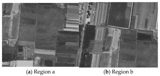
Precision localization primarily relies on local features extracted from images. These local features, such as points, lines, and planes, are detected and matched using geometric feature extraction methods, including SURF [6], ORB [7], and LSD [8]. With the rapid advancement of deep learning, learning-based feature extraction techniques, such as SuperPoint [9], LETR [10], and LoFTR [11], have also been widely adopted in this domain. The UAV position is solved using different geometric models based on whether the spatial positions of the matched features include altitude. When altitude is unavailable, methods such as the homography transformation model [12] and the AH-epipolar model [13] are applied. In contrast, when altitude is available, models like EPNP [14], UPnP [15], and MLPnP [16] can be used to locate UAVs.
Coarse localization relies on global features in the image, primarily involving the overall grayscale distribution [17], semantic information [18], spatial relationships [19], global features extracted by a deep learning network [20], and other statistical information. UAV localization is achieved by computing the feature vector of the aerial image and retrieving the most similar match from the pre-built database. Zhuo et al. [21] proposed a high-resolution remote sensing image retrieval method with Gabor-CA-ResNet and a split-based deep feature transform network, significantly reducing feature dimensions and storage space. Shan et al. [22] used Inception Net to extract deep features from remote sensing images and employed a hard probability sampling hash retrieval method to enhance both the accuracy and efficiency of remote sensing image retrieval. Aside from directly computing global features from images by a deep learning network for localization, semantic information is also commonly used for coarse localization. Buildings and Roads, as two semantic categories with relatively fixed geometric configurations in remote sensing images, are widely used for localization. Buck et al. [23] constructed semantic features for localization by calculating the proportion of the building region in the image. Wang et al. [24] proposed localization methods using the topological relationships between road intersections. These methods perform high localization accuracy in urban scenes. In addition to using single semantic information for localization, many methods employ multiple types of semantic information. Schmidt et al. [25] utilized semantic categories such as buildings and roads in aerial images to construct a category matrix for localization. Li et al. [26] proposed a localization method by constructing semantic features based on the region ratios of semantic features in segmented reference maps. Considering the structural stability of topological structures, He et al. [27] proposed a UAV localization method based on semantic topological feature matching of distance ratio, normalized angular differences, and semantic labeling information. Tang et al. [28] constructed scene graph feature vectors containing a nine-intersection topological structure based on the semantic and orientation information.
The hybrid localization methods combine both local and global features for localization. Zhou et al. [29] employed DINOv2 for coarse localization, followed by an improved SuperPoint network for precise localization. Ye et al. [30] proposed a localization method using Segments Direction Statistics (SDS) features for coarse localization, and they then utilized SuperPoint for precision localization. Liu et al. [31] used QATM SqueezeNet for coarse matching to quickly obtain an approximate location, and they employed SuperGlue for precision matching. Methods based on hybrid localization can further extract features on the basis of coarse localization to achieve precise localization, effectively improving localization accuracy.
Precise localization and hybrid localization typically require an initial coarse localization step to achieve candidate matching regions. However, coarse localization methods based on retrieval have several limitations. Firstly, the construction of feature vectors is limited by the window size and the sliding step size. The method based on retrieval needs to traverse the entire reference map, resulting in a significant amount of redundancy in feature storage. Secondly, the database consists of digital orthophotography images with a fixed field of view and pose. Such methods struggle to adapt to variations in the field of view and attitude caused by changes in flight altitude and attitude in real aerial images. To address these difficulties, inspired by the cross-view location localization method based on natural language descriptions in reference [32], a localization method based on unique semantic features is proposed. The method is developed by thoroughly exploring the distinctions and individual characteristics among semantic instances in the mission region and constructs robust semantic feature vectors from unique semantic instances for localization.
Our main contributions are as follows:
- The semantic characteristics of different types of targets in remote sensing images are analyzed, and a method for selecting unique semantic instances that align with the characteristics of natural language description is proposed.
- A novel localization framework based on unique semantic instances is proposed and applied to UAV localization.
- The effectiveness of the proposed method is verified by synthetic data and flight data. The robustness and adaptability of the proposed method are greatly improved in the task region.
The structure of this paper is organized as follows: Section 2 presents a localization method based on unique semantic features, detailing the construction of a unique semantic feature database and the process of UAV localization. Section 3 describes the UAV platform, data acquisition, and the experimental results of the method proposed in this paper, along with the results of contrast methods. Section 4 discusses the performance of the method and its advantages in storage and speed. Finally, Section 5 presents the conclusion.
2. Materials and Methods
2.1. UAV Localization Framework
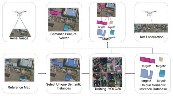
The method framework is shown in Figure 1. Based on the mission region of the UAV, unique semantic instances are first selected to construct the database. The instance segmentation model based on YOLO26 [33] is trained to construct a database of unique semantic instances. During UAV localization, semantic features are extracted from the aerial image to obtain the semantic feature vector of the current aerial image. The semantic feature vector constructed from the aerial image is then matched with the constructed semantic instance database to locate the UAV.
Figure 1.
UAV localization framework with unique semantic features.
2.2. Analysis of Reference Map Characteristics and Semi-Automated Selection of Unique Instances
The reference map contains rich semantic information for localization, but the repetition level of semantic information varies significantly. For instance, forests and lakes are both scenes with a high repetition level. In narrow fields of view, aperture effects make it difficult to recognize the region’s location on the map. In contrast, some man-made structures with unique appearances have a low repetition level can be easily identified. Based on the varying repetition levels of semantic information, semantic instances are classified into two categories:
- Unique semantic instances: These instances are inherently unique, with no identical or similar scenes in the environment, such as buildings with distinctive shapes.
- Repetitive semantic instances: These instances are not inherently unique and have multiple similar scenes in the environment, such as lakes or forests.
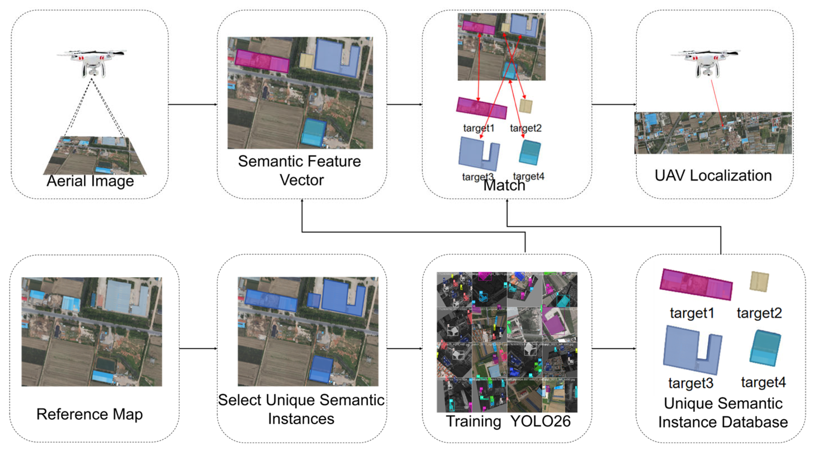
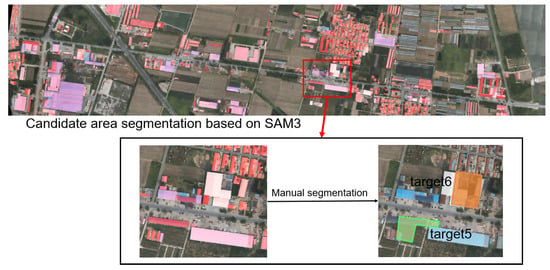
Inspired by reference [32], which uses natural language descriptions for cross-view text-geolocation matching, this paper aims to fully exploit semantic information in images by combining multiple repeated semantic instances into a unique semantic instance for localization. As shown in Figure 2, three buildings and some forests can be combined into a unique instance for localization. A semi-automated screening strategy is used to select unique semantic instances for localization. Some objects, such as vehicles and paddy fields, vary significantly over time or with the seasons. For this reason, we use the SAM3 model [34] to detect the “building” category to obtain candidate regions. The detected building regions are then automatically filtered based on their confidence scores. As shown in Figure 2, the regions highlighted in red represent all candidates classified as “building” by the SAM3 model.
Figure 2.
Semi-automated Selection of Unique Instances.
After automatically filtering candidate regions, manual segmentation is required to further select and segment the boundaries of unique semantic instance regions. As shown in Figure 2, based on instance segmentation of buildings, two unique semantic instances are then selected from the candidate regions. This semi-automatic method for selecting unique semantic instances can replace the target vocabulary of the SAM3 model based on the actual scene of the task regions. Targets with less variation in features in the scene are preferred. This method has a certain generalization ability, except for scenarios such as the sea surface.
2.3. Acquisition of Unique Semantic Instance Database
The construction of semantic feature vectors in the unique semantic instance database consists of two parts: the first part is the category of the semantic instance, and the second part is the position of the centroid of the semantic instance. The unique semantic instance database is shown in Equation (1).
where and are the set of semantic labels containing semantic instances and the set of positions of the centroids of these semantic instances on the reference map. is the number of selected instances in the region, within the range of [1, 40] in this paper. is the centroid of the K-th semantic instance. is the set of closed contours of the K-th semantic instance. can be obtained by Equation (2).
where is the number of points of the closed contour of the K-th semantic instance.
The unique semantic instances in the flight mission region are preselected, and their corresponding centroids are solved based on Equations (1) and (2). The semantic feature vectors corresponding to all unique semantic instances in the mission region are then collected to form a unique semantic instance database for localization.
2.4. UAV Localization Method Based on Unique Semantic Feature Vectors
The UAV location based on the unique semantic feature vector is divided into two steps: the first is feature matching based on the semantic feature vector of the aerial images, and the second is the location region correction based on the semantic feature vector.
Firstly, the semantic instance is extracted from the aerial image based on the segmentation model, and then the semantic feature vector of the aerial image is constructed, as shown in Equation (3).
and represent the set of semantic labels of the semantic instances detected from the aerial image and the set of their corresponding centroids. is the number of instances detected in the aerial image, with a range of .
contains prior semantic labels for the mission region, and contains semantic objects in the aerial image. Let be the i-th semantic label in and be the label in that shares the same semantic label as . Retrieving the semantic label of from yields the corresponding label , completing the matching between and . By retrieving and matching semantic category information between of the aerial image and of the database, the instances on the aerial image can match the instances on the map. After matching the with the in the database, and can be matched based on the matched category. The localization region is then corrected using the angular relationship between and to improve localization accuracy. Depending on the number of semantic instances, the localization region correction scheme can be divided into three cases:
- (1)
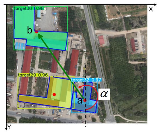
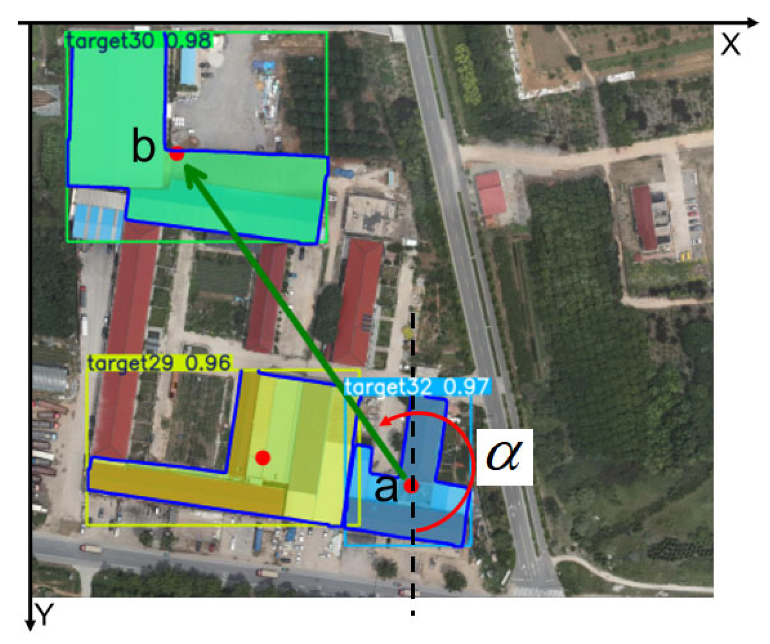
- When k ≥ 2, as shown in Figure 3, the feature vector constructed from the top two points by the instance segmentation confidence score in the point set {pk} is used to generate the feature centroid and feature angle of the aerial image. The feature vector is defined as the vector pointing from the centroid of the semantic instance closer to the image center to the centroid of the other point. In Figure 3, the feature vector is the vector pointing from the centroid a of target32 to the centroid b of target30. The feature angle α of the aerial image is the angle between the feature vector and the positive Y-axis. The centroid a of the semantic instance target32, which is closer to the image center, is referred to as the feature centroid (xa, ya) of the current aerial image.Figure 3. Feature centroid and feature angle in the aerial image. Red points are the centroids of the recognized semantic instances. The green arrow from point a to point b represents the feature vector of the aerial image. The red arc is the feature angle of the aerial image.
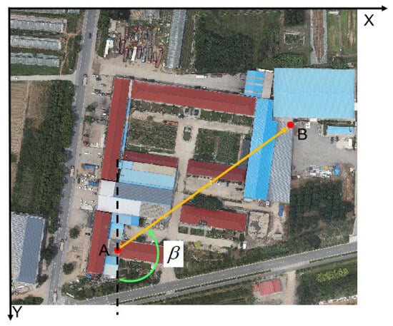
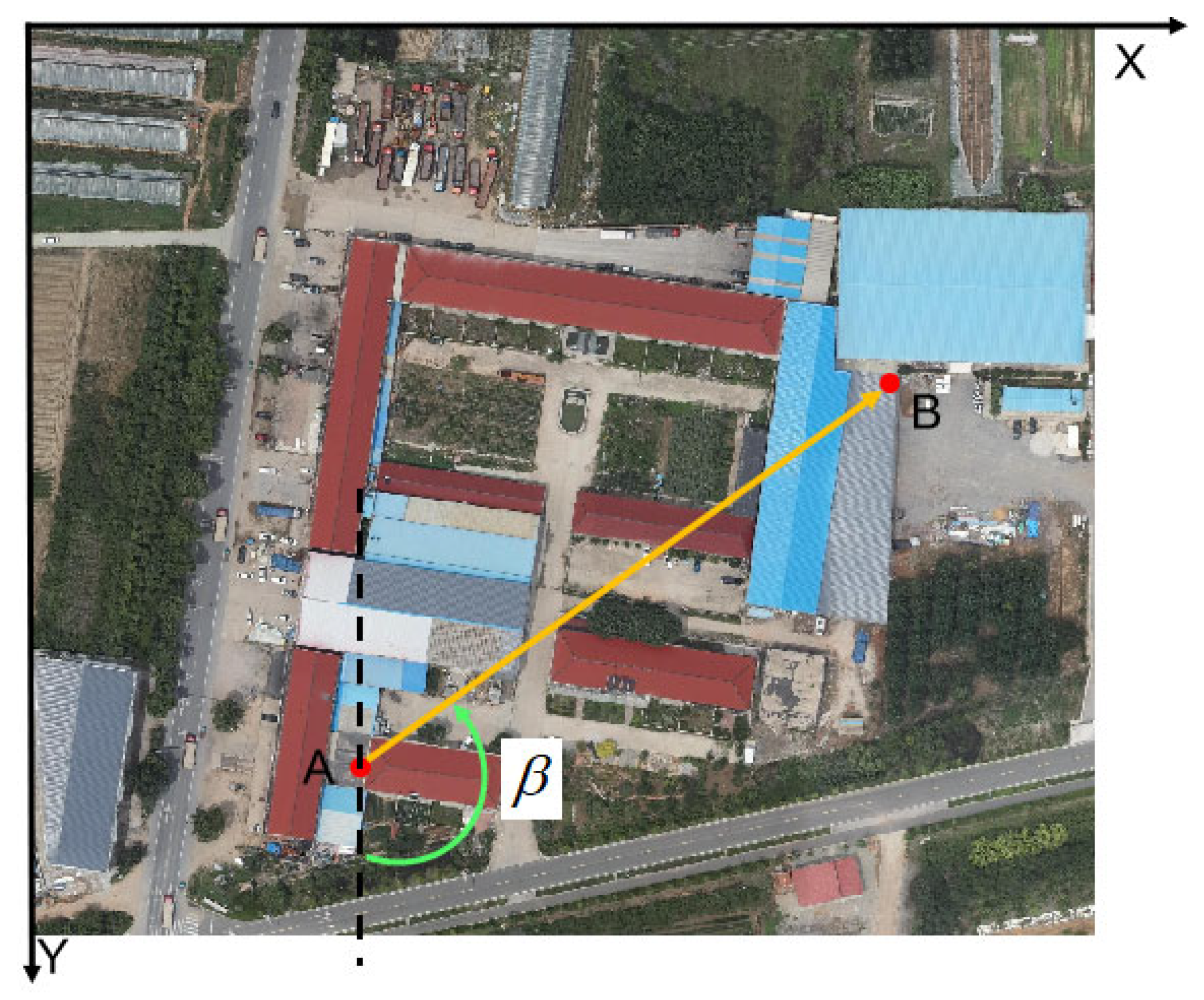
Based on the semantic instances detected in the aerial image, the positions of the centroids of the corresponding semantic instances on the reference map can be obtained from . As shown in Figure 4, with the semantic instances target32 and target30 in the aerial image, the corresponding feature angle and feature centroid of the reference map can be made. The feature angle of the reference map is the angle between the vector pointing from the centroid A of instance target32 to the centroid B of instance target30 and the positive Y-axis. is the coordinate of point A on the reference map.
Figure 4.
Feature centroid and feature angles in the reference map. The orange arrow from point A to point B represents the feature vector of the reference map. The green arc is the feature angle of the reference map.
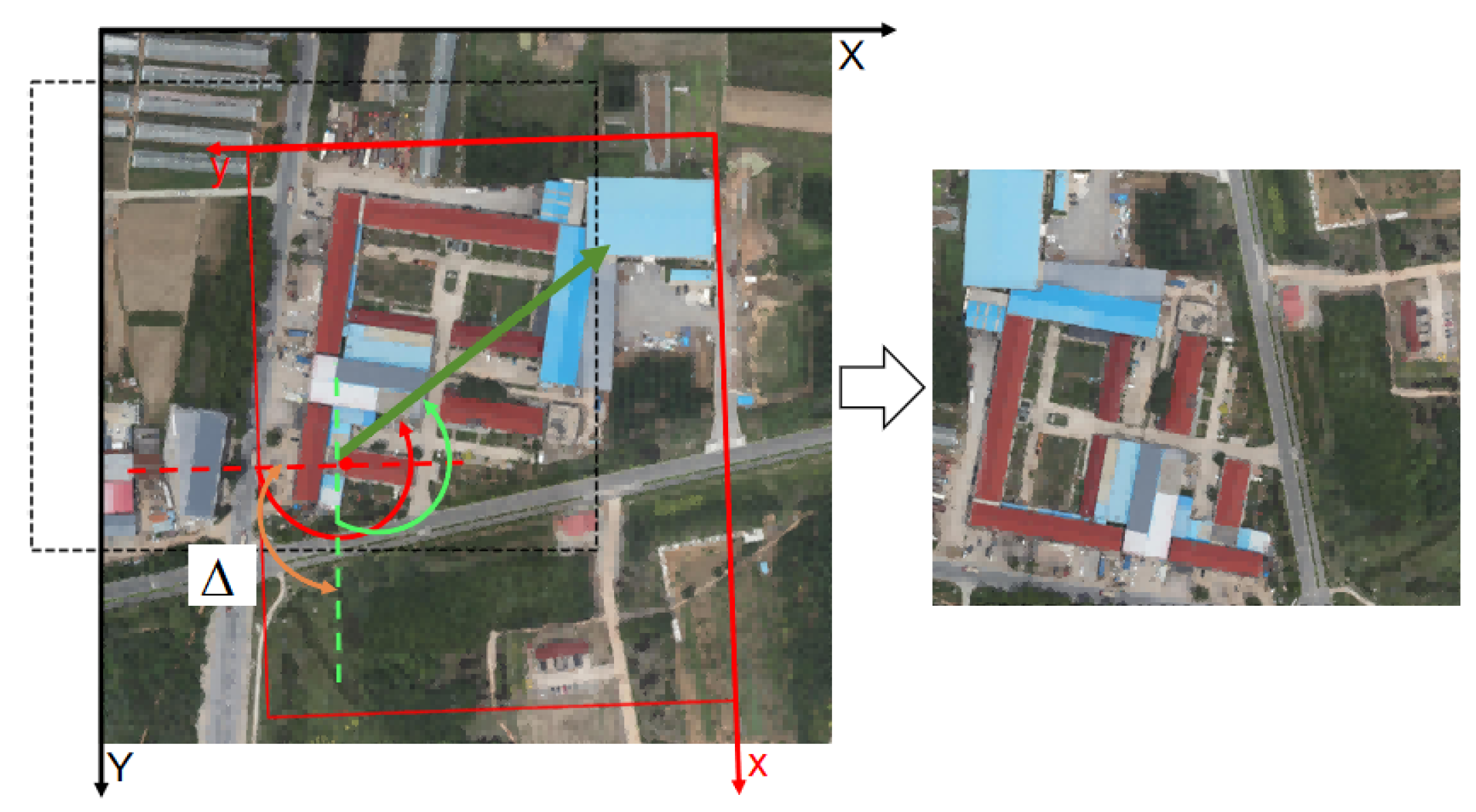
Based on the positions of the feature centroid in the aerial image and the feature centroid on the reference map, the uncorrected localization region of the UAV can be obtained. As shown in Figure 5, the region of the black dashed box is the obtained initial localization region, which can be calculated by Equation (4).
Figure 5.
Result of UAV localization. The red x-axis and y-axis are the x-axis and y-axis of the aerial image. The black dashed box represents the uncorrected localization region. The red solid box represents the corrected localization region, and the red dashed line is an auxiliary line parallel to the y-axis. The orange arc is the correction angle.
Taking as the rotation center and the between the feature angle of the aerial image and the reference map as the rotation angle, the optimized localization region can be obtained. As shown in Figure 5, rotating the black dashed box clockwise around point A by to obtain the red rectangle, which is the result of UAV localization.
- (2)
- When k = 1, since it is difficult to obtain yaw angle information from a single semantic instance, it is assumed that there is no angular difference between the aerial image and the reference map, and the localization region is directly obtained using Equation (4).
- (3)
- When k = 0, effective localization cannot be achieved.
3. Results
In this section, the performance of the proposed method is validated using both simulation data and flight data. Method A [27] and Method B [26] are selected for comparison with the proposed method. Methods A and B extract global features of the image and use geometric parameters such as length ratio and area ratio for localization, which have strong adaptability to changes in scale. Method A constructs feature vectors for localization using the distance ratio and normalized angular differences between each semantic category’s centroid and the image center, along with semantic labeling information. In Method A, a 2448 × 2048-sized image is cropped with a step size of 500 pixels to extract features and construct a feature database. Method B constructs feature vectors based on the area ratio of various semantic objects in the image. In Method B, the reference map is segmented into a 2448 × 2048 region for feature extraction and vector construction.
3.1. Construction of Unique Semantic Instance Database and YOLO26 Training
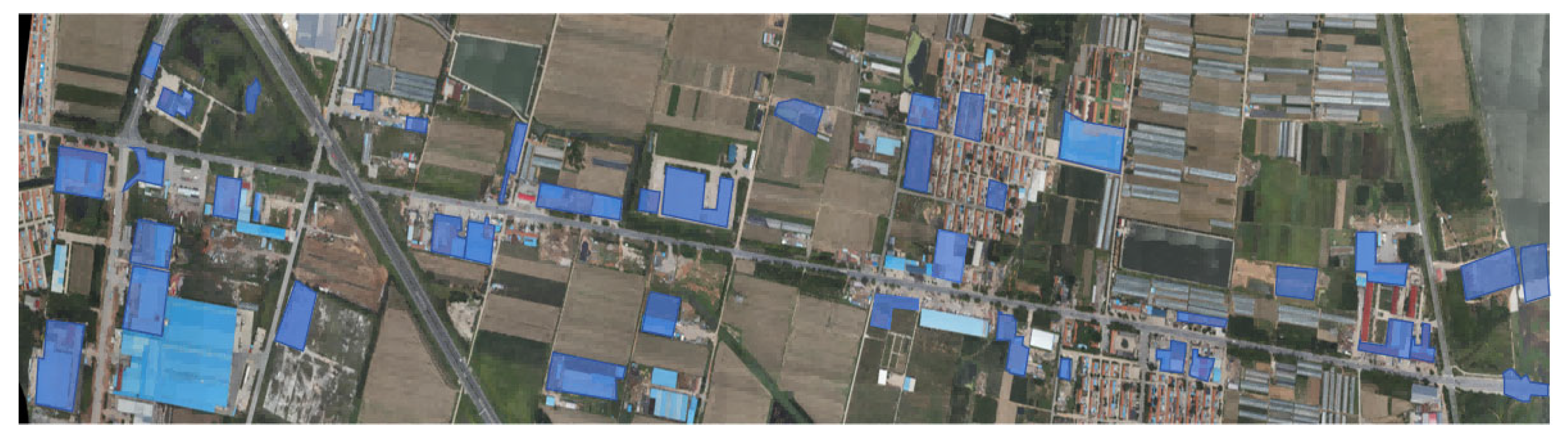
To construct a unique semantic instance database, aerial images were captured in advance with a DJI Phantom constructing a reference map, and the reference map was generated using DJI Terra in spring, at a certain location in Shandong. As shown in Figure 6, the map covers a region of approximately 5 km × 1 km, with an image size of 27,501 × 5701 pixels. The blue masks represent unique semantic instances. A total of 40 unique semantic instances were selected to locate UAV.
Figure 6.
Reference map and distribution of unique semantic instances.
To effectively extract unique semantic instances in images, the YOLO26 was selected to train an instance segmentation model. The reference map was randomly cropped into patches of 2000 × 2000 pixels. The aerial and cropped reference images were grayscaled and then rotated by 90°, 180°, and 270° for data augmentation to enhance the network’s adaptability to different yaw angles. The total number of images in the dataset was 1536, which were divided into training and validation sets in a 9:1 ratio. The semantic instances in the database were annotated by LabelMe (Version 5.3.0a0) software. The training set contains 1383 images with 2991 instances, while the validation set has 153 images with 315 instances.
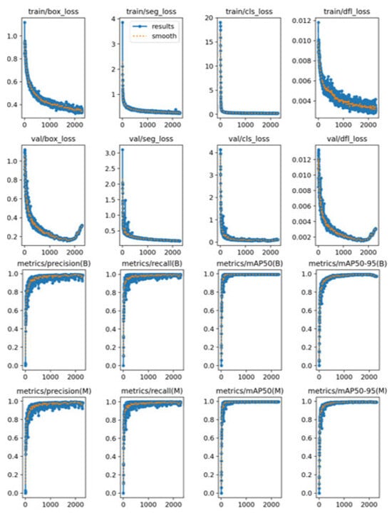
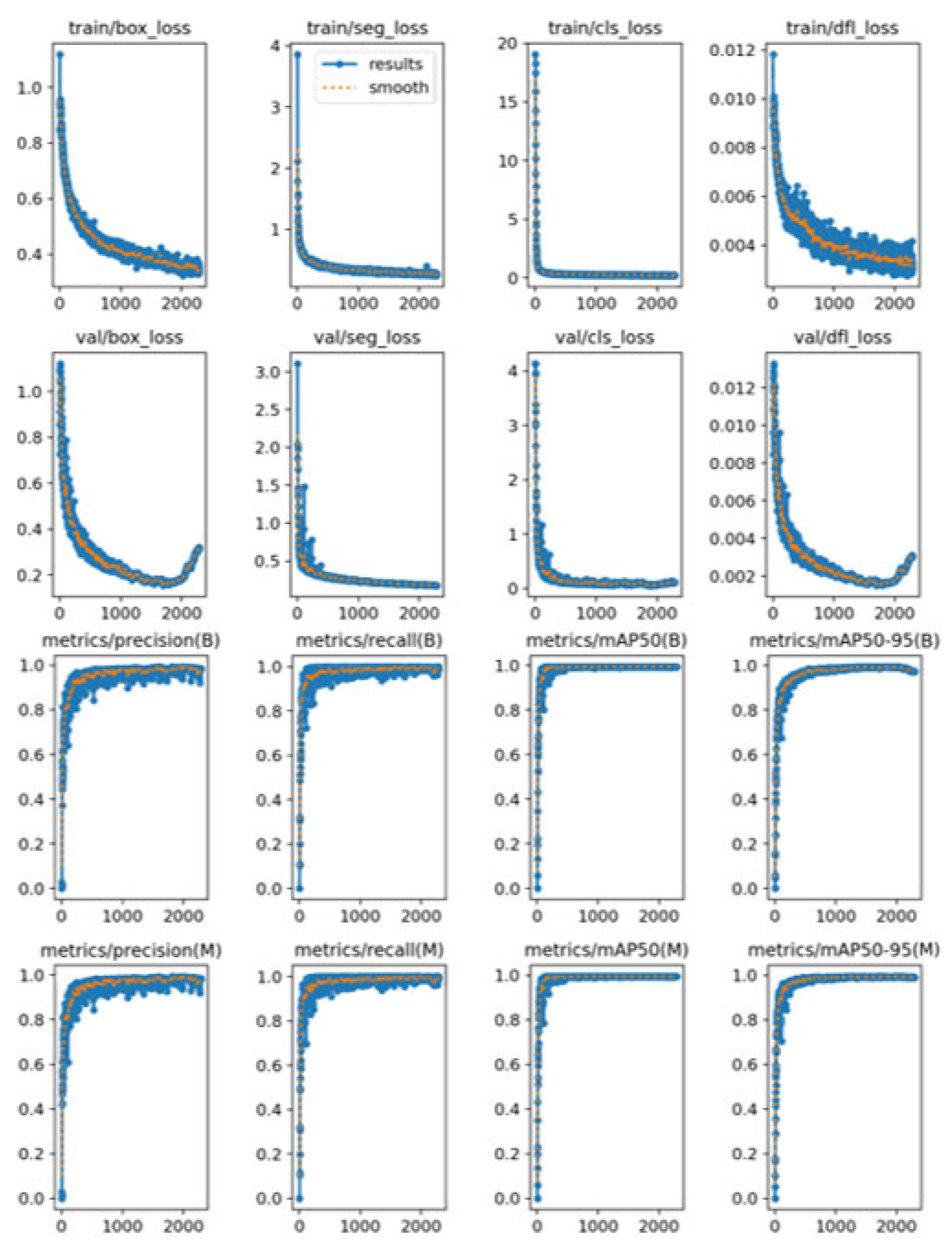
The training environment was Ubuntu 20.04 with an NVIDIA RTX 5070 GPU. To improve the network’s adaptability to variations in illumination, attitude angle, and scale, the training parameters for YOLO26 were set as follows: hsv_h = 0.015, hsv_s = 0.7, hsv_v = 0.4, degrees = 90, scale = 0.5, batch = 16, patience = 500, Epoch = 5000, and the learning rate uses the default value. The training results are shown in Figure 7. The training stopped early at epoch 2235. Due to the selected training parameters of patience being 500, the model trained 1735 times was chosen for subsequent instance segmentation.
Figure 7.
Training results of YOLO26.
3.2. Experiments with Synthetic Data and Analysis
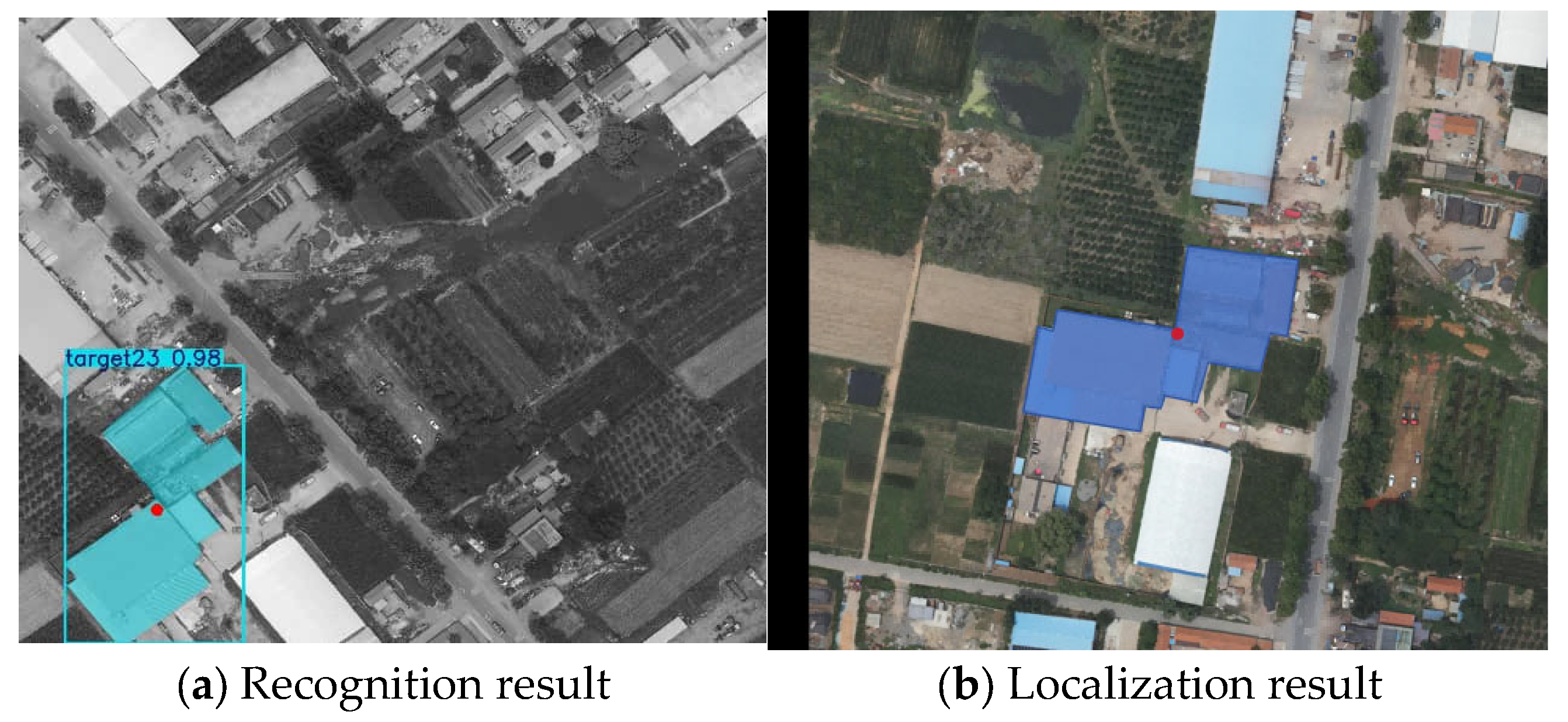
The homography matrix between the aerial image and the localization region is solved to determine the localization error using the distance between the center points of the images [12]. As shown in Figure 8, when the number of feature points is 1, according to the proposed method, the localization result is only related to the location of the semantic instance in the aerial image, resulting in localization errors. Due to the size of the aerial image being 2448 × 2048, the maximum localization error is the distance from the center of the image to the corner of the aerial image, which is 1596 pixels. Therefore, distances of more than 1596 pixels are considered localization failures.
Figure 8.
Localization result with 1 instance. Red points are the centroids of the recognized semantic instances.
To further compare the localization accuracy of the methods, we denote the number of correct localizations and failed localizations as and . The success rate is set as . is calculated by Equation (5).
3.2.1. Localization Results and Analysis of UAVs in Level Flight State
Assume that the camera is rigidly fixed to the UAV. The localization performance of these methods is tested by simulating aerial image data captured during level flight. A total of 100 aerial images of size 2448 × 2048 pixels are cropped from the reference map at random positions and with random yaw angles.
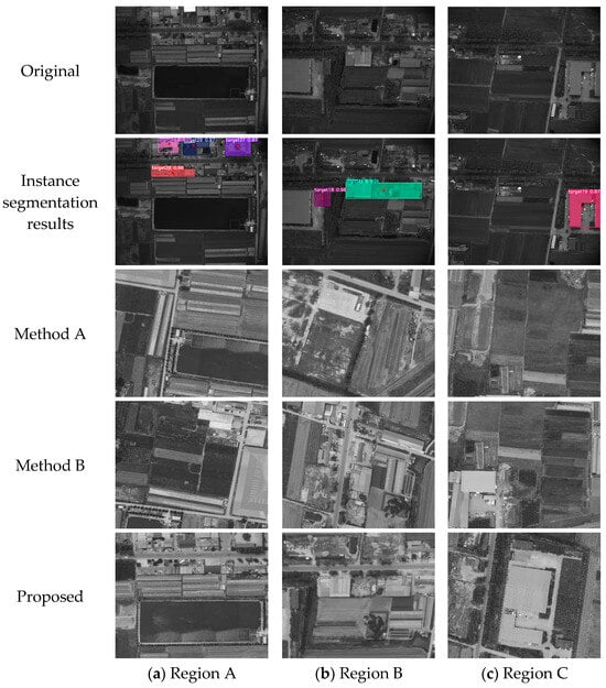
As shown in Figure 9, compared with methods A and B, the proposed method has significantly higher localization accuracy when . When , the errors of the three methods are close. Unlike methods A and B, the proposed method can restore the yaw angle of the image and improve the localization accuracy.
Figure 9.
Instance segmentation and localization results under level flight conditions.
The methods are compared with matching accuracy, mean localization error, median localization error, and standard deviation of localization error. The experimental results are shown in Table 1.
Table 1.
Localization results under level flight conditions.
As shown in Table 1, the proposed method achieves a localization success rate of 98% by using unique semantic feature matching. It failed to locate successfully in only two regions, both of which lacked semantic instances. Method A has a localization success rate of 92% and a mean localization error of 331.26 pixels. Method B has the worst positioning success rate and positioning error.
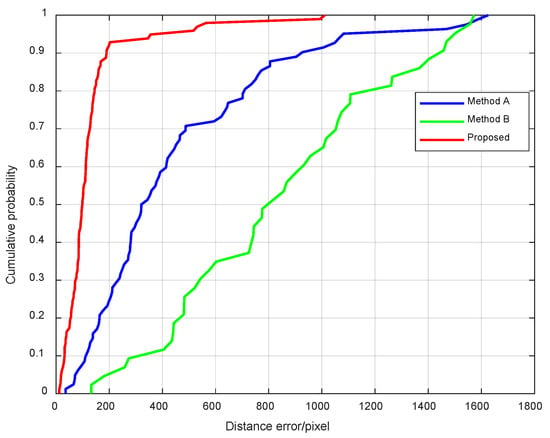
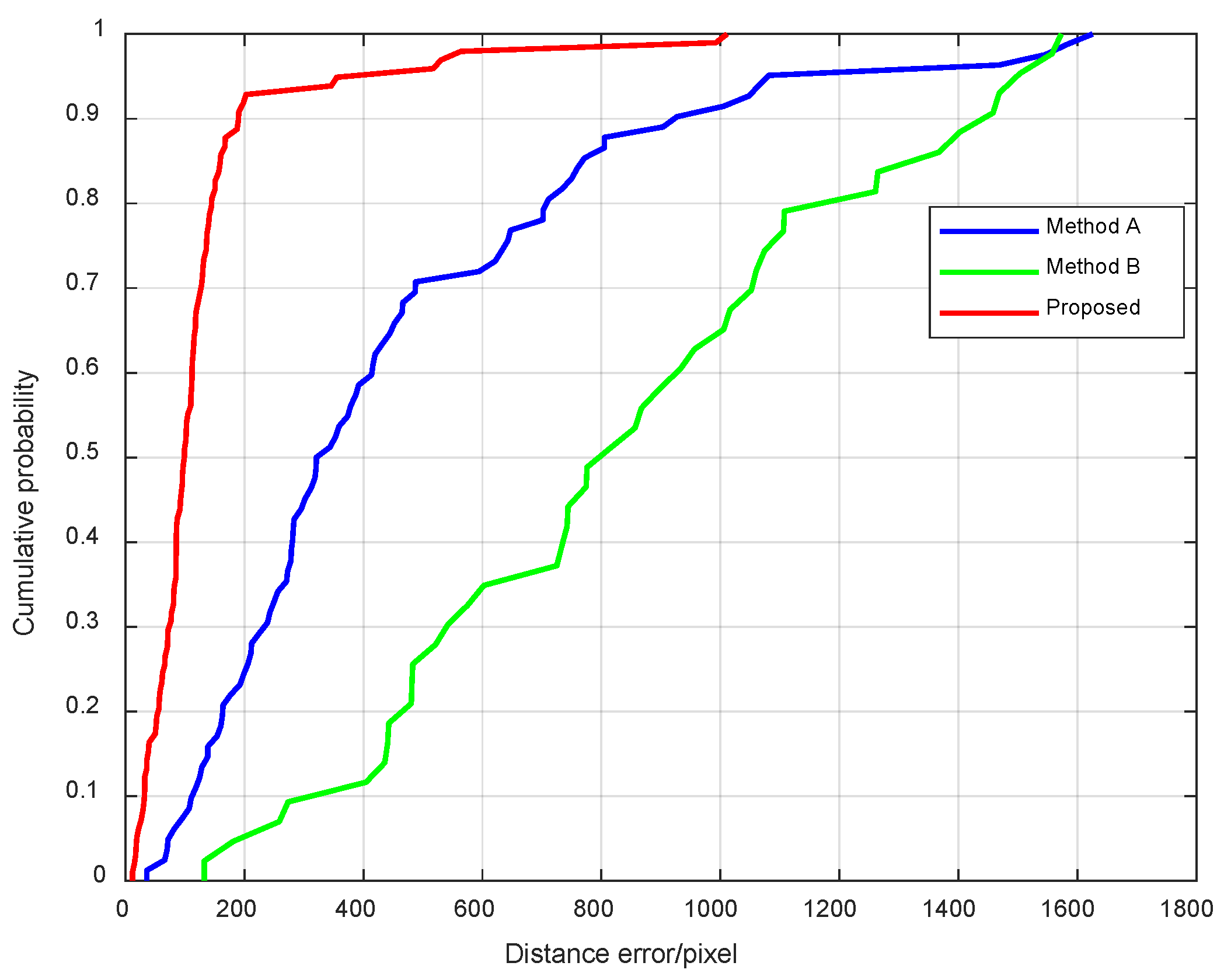
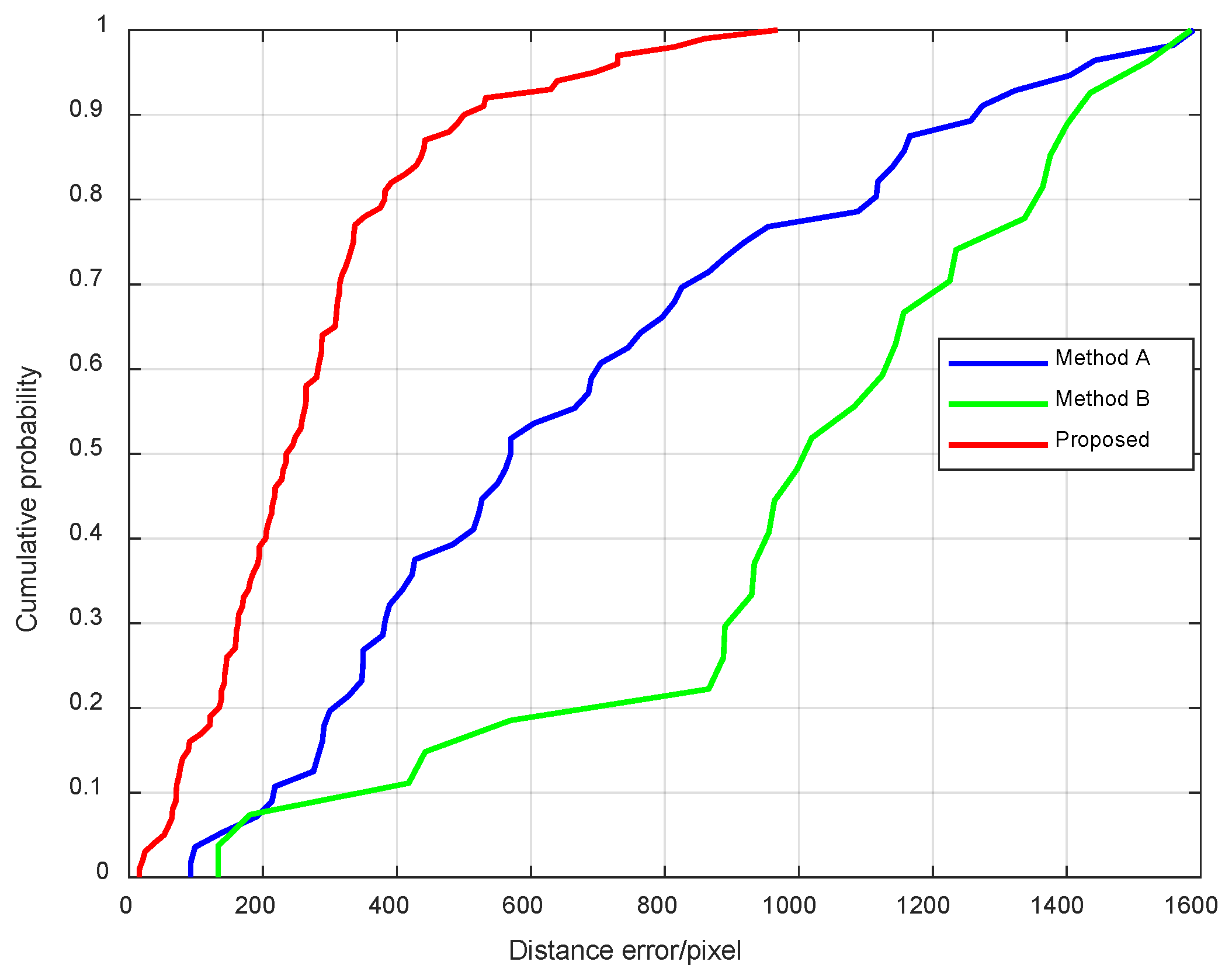
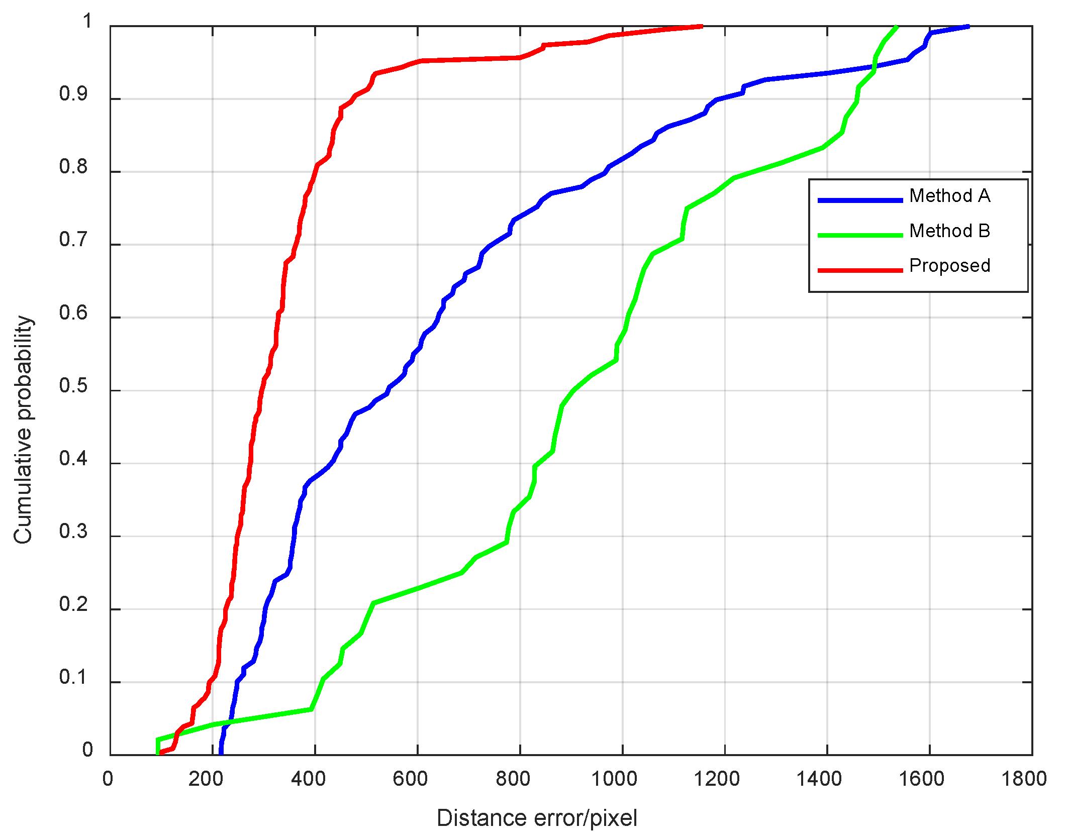
The cumulative distribution function of the three methods is shown in Figure 10.
Figure 10.
Cumulative distribution function results under level flight conditions.
As shown in Figure 10, the proposed method has good localization accuracy in 90% of the test regions, with localization errors less than 200 pixels. However, it has significant errors in some regions. In order to further illustrate the performance of the proposed method, the average localization error, median, and standard deviation of the method with different numbers of instances in aerial images are calculated. The results are shown in Table 2.
Table 2.
Localization errors with a different number of instances under level flight conditions.
As shown in Table 2, when , the proposed method in this paper can achieve higher localization accuracy. When , the localization accuracy is greatly affected by the position of the instance in aerial images.
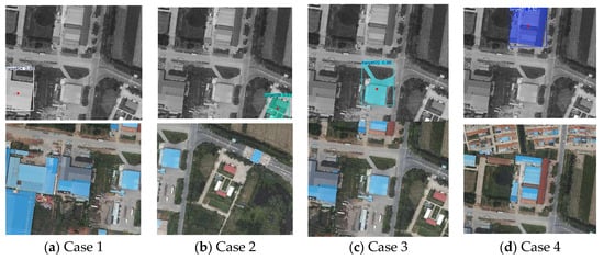
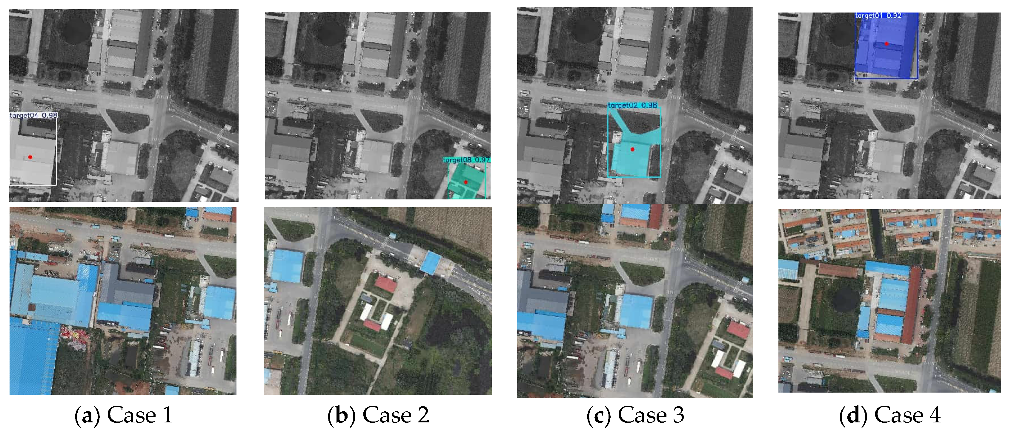
The unmatched regions of the proposed method are shown in Figure 11. These regions mainly consist of natural landscapes such as rice fields, woods, and lakes. The absence of the semantic instances used in the proposed method prevents UAVs from localizing themselves in these regions.
Figure 11.
Unlocalized regions of the proposed method.
Except for the regions shown in Figure 11, all scenes contain at least one semantic instance. YOLO26 can effectively detect semantic instances, enabling more stable localization.
3.2.2. Localization Results and Analysis of UAVs in Non-Level Flight State
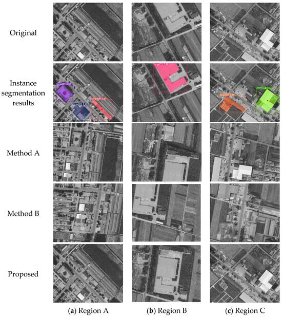
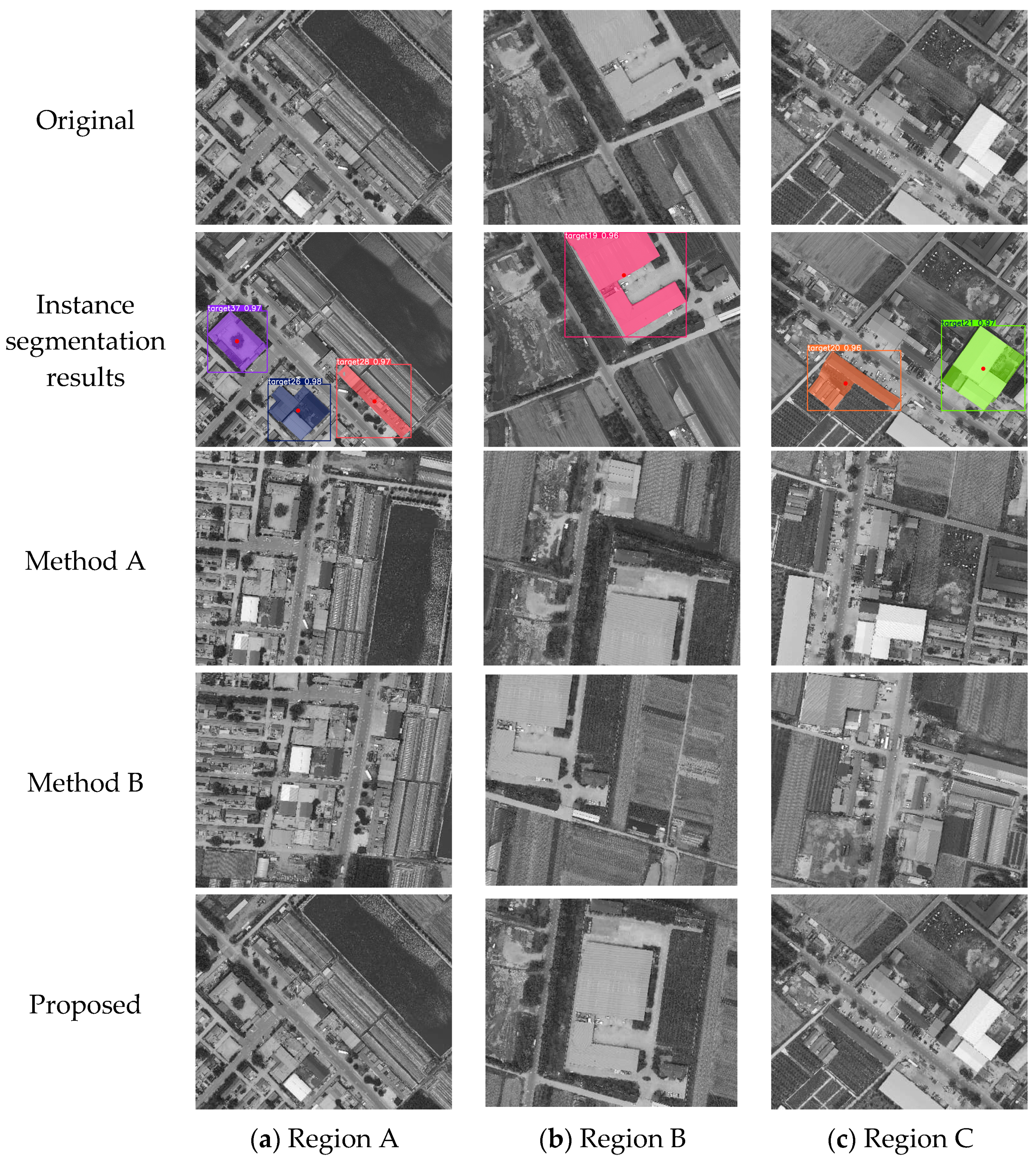
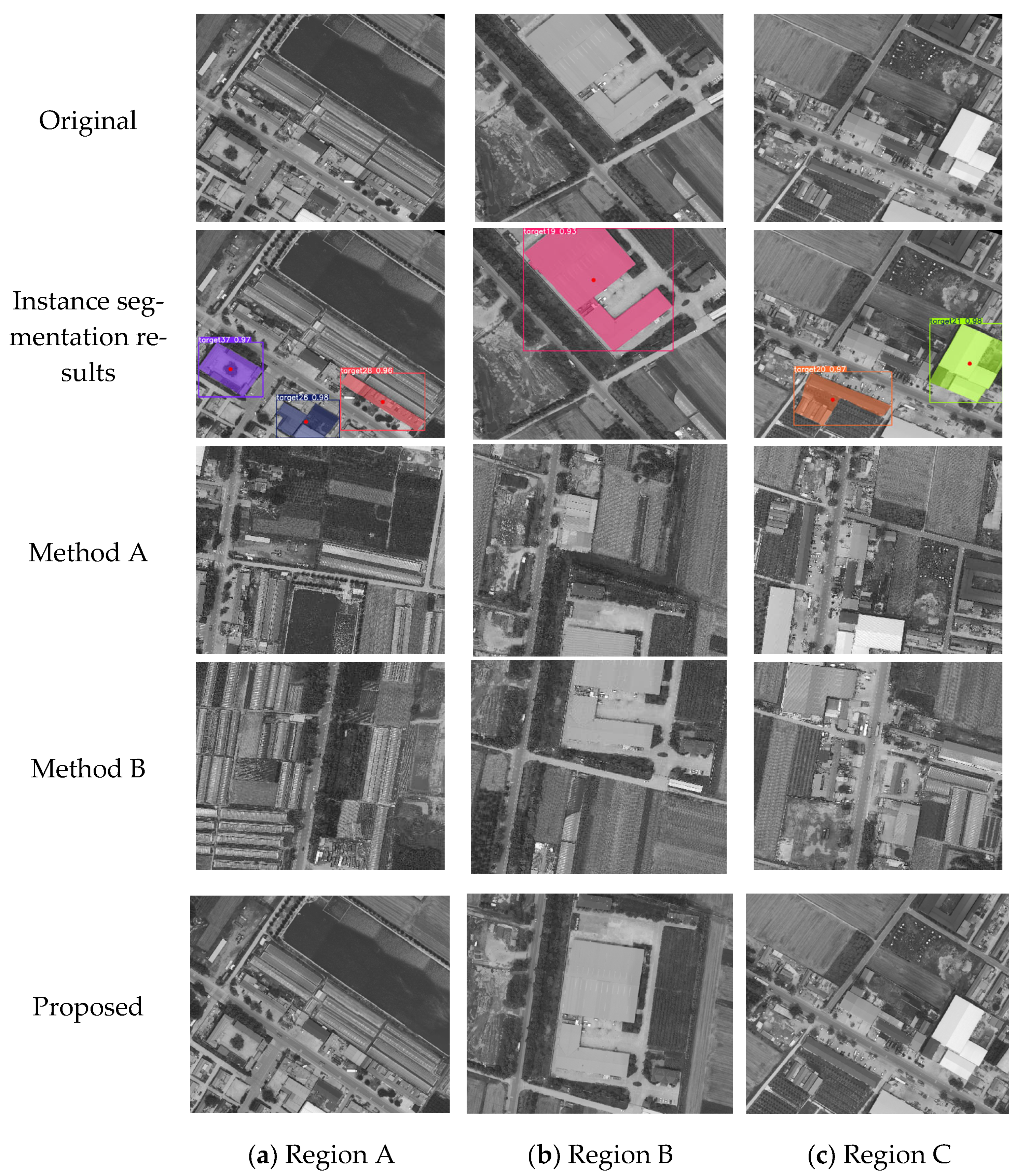
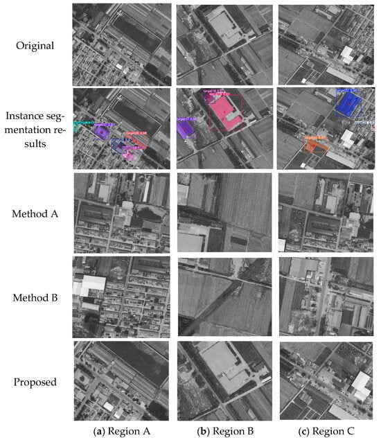
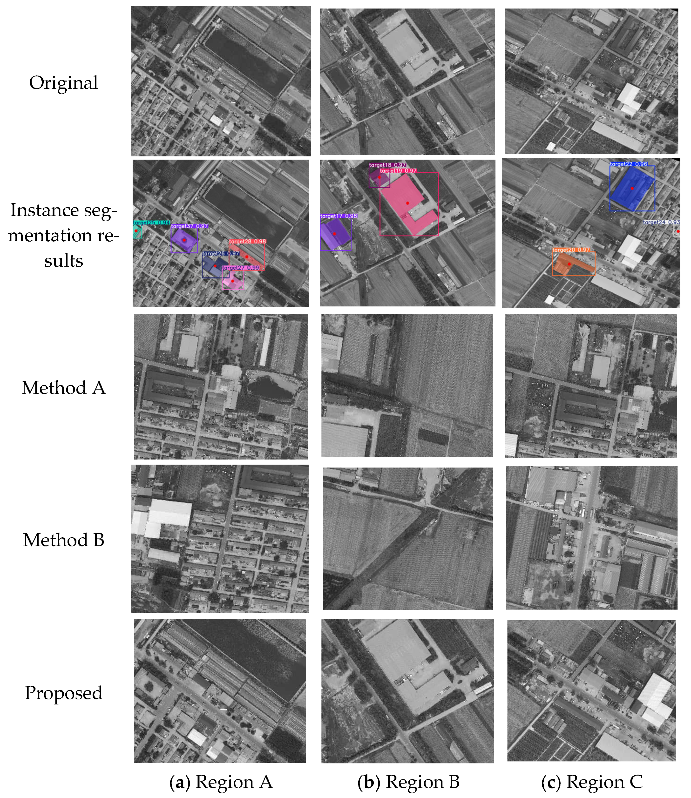
Considering that when the camera is rigidly attached to the UAV, aerial images are inevitably affected by UAV vibrations. To further verify the localization capability of the methods under the influence of aerial images caused by changes in the UAV’s attitude. Based on the yaw angle described in Section 3.2.1, random pitch and roll angles ranging from 0° to 10° were added to the UAV’s attitude. The localization results are shown in Figure 12.
Figure 12.
Instance segmentation and localization results under non-level flight conditions.
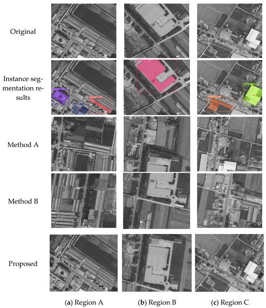
As shown in Figure 12, compared with Methods A and B, the proposed method can still effectively detect unique semantic instances in the field of view for localization. The localization results of three methods under non-level flight conditions are shown in Table 3.
Table 3.
Localization results under non-level flight conditions.
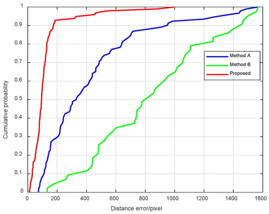
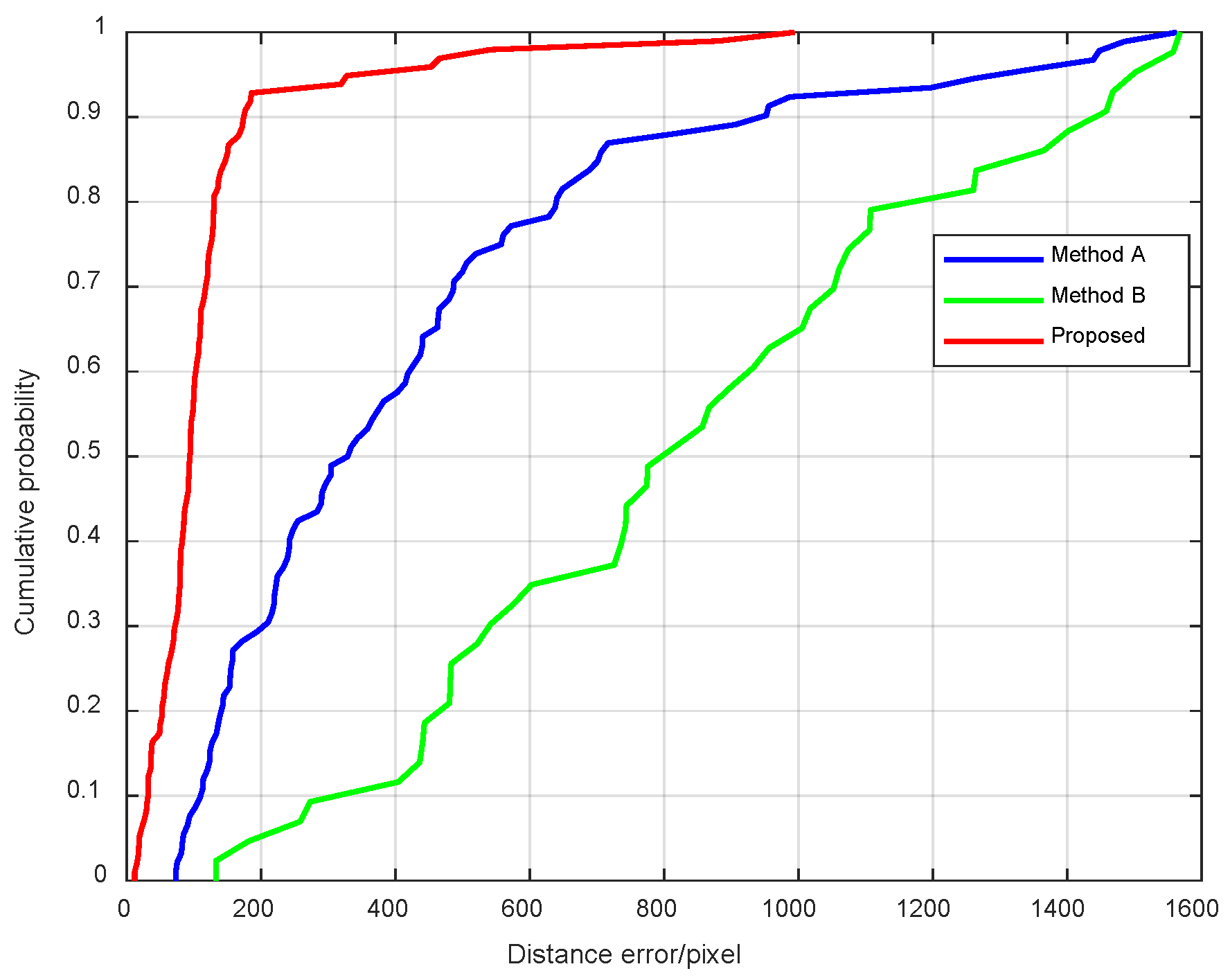
As shown in Table 1 and Table 3, the mean localization error, median localization error, and standard deviation of localization error of all three methods increased. However, the proposed method still recognizes instance targets when the attitude of the UAV changes. The localization success rate of Method A decreased from 92% to 82%, while Method B increased from 41% to 44%. The cumulative distribution function of the three methods is shown in Figure 13.
Figure 13.
Cumulative distribution function results under non-level flight conditions.
The results in Figure 13 are similar to those in Figure 10. The localization errors of the proposed method with different numbers of instances in aerial images are shown in Table 4.
Table 4.
Localization errors with different numbers of instances under non-level flight conditions.
As shown in Table 4, when , the proposed method can achieve higher localization accuracy, and the improvement in accuracy gradually decreases.
3.2.3. Localization Results and Analysis of UAVs at Higher Altitudes
The flight altitude of a UAV inevitably affects aerial images, leading to changes in the field of view and pixel resolution. Adjusting the field of view and downsampling the image to simulate changes in flight altitude. Considering that an excessively low flight altitude would result in a narrow field of view, making it difficult to identify unique instances of a target, the images were downsampled at a random scale in the range of 1 to 2 times in this paper. The localization results are shown in Figure 14.
Figure 14.
Instance segmentation and localization results at higher altitudes.
As shown in Figure 14, due to the scale difference between the aerial image and the reference image, errors were introduced during the localization process. As shown in Figure 14c, one instance was missed, but at a higher altitude, the proposed method obtained a wider field of view and still effectively localized. The localization results at higher altitudes are shown in Table 5.
Table 5.
Localization results at higher altitudes.
As shown in Table 5, higher flight altitudes result in a larger field of view for the proposed method, which is beneficial for localization. Although the localization error increases with altitude, the localization success rate improves. In contrast, Methods A and B are significantly affected by changes in the field of view, leading to lower success rates and higher errors. Figure 15 shows the cumulative distribution functions of the three methods.
Figure 15.
Cumulative distribution function results at higher altitudes.
As shown in Figure 15, the localization errors of all three methods have increased. The localization errors of the proposed method with different numbers of instances in aerial images are shown in Table 6.
Table 6.
Localization errors with a different number of instances at higher altitudes.
According to Table 6, when , the localization error is significantly smaller than when . The localization error approaches when .
3.3. Experiments with Flight Data
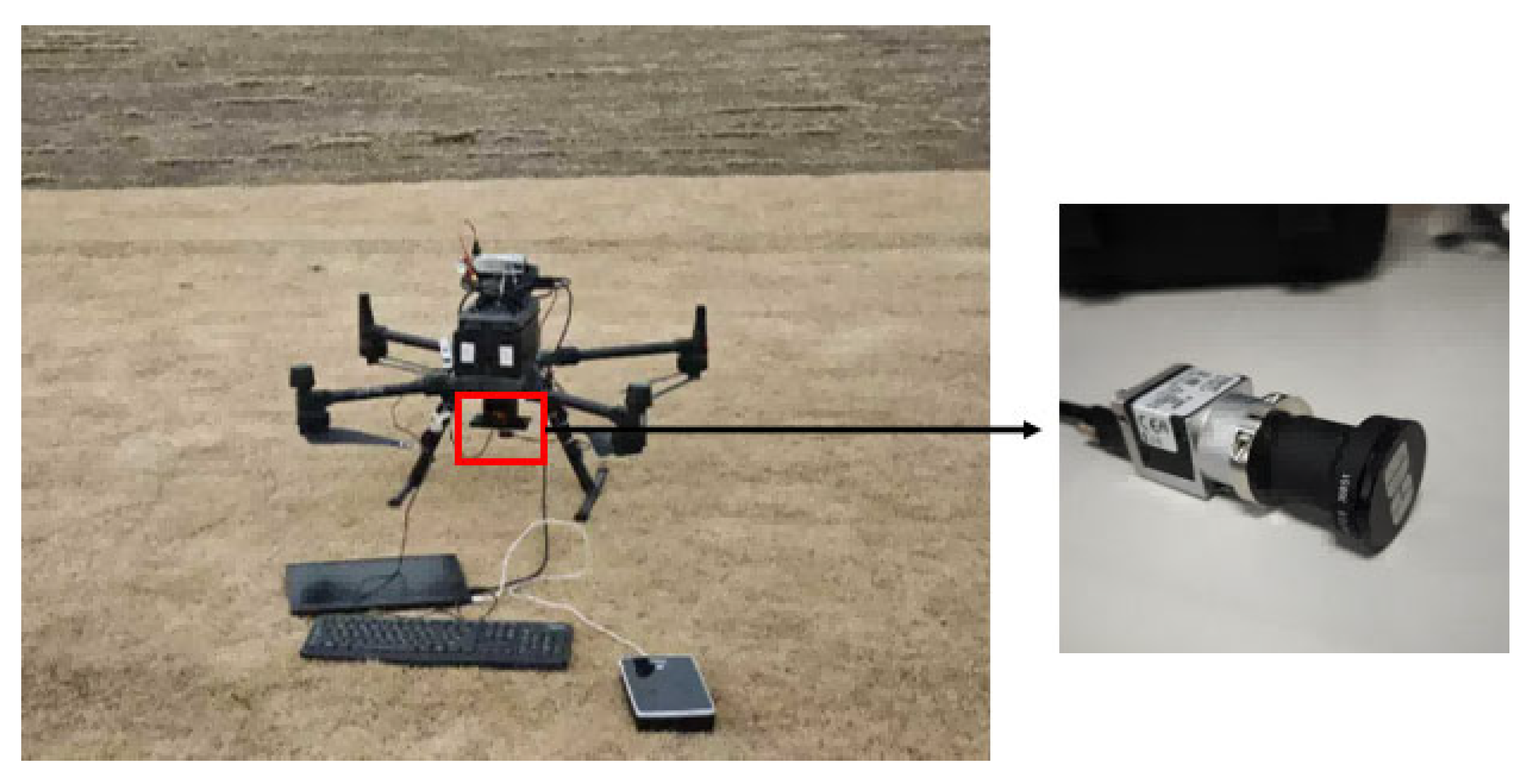
To further analyze the localization performance of the methods, flight data were collected to test the localization performance of the two methods. As shown in Figure 16, in spring, at a certain location in Shandong, a DJI M300 (DJI, Shenzhen, China) was used to collect flight data at an altitude of 500–550 m. The camera was fixed on the UAV, and the lens and CMOS models were BASLER (Basler AG, Ahrensburg, Germany) and MV-CH050-10UM (Hikrobot, Hangzhou, China).
Figure 16.
Experimental hardware equipment.
As shown in Table 7, the intrinsic matrix and distortion parameters of the camera were obtained using the Kalibr toolbox [35] (https://github.com/ethz-asl/kalibr, accessed on 15 February 2026).
Table 7.
Intrinsic parameters and distortion parameters.
The flight image dataset consists of 234 images. Variations in UAV’s altitude and attitude introduce attitude angle differences of 0° to 10° and differences in the field of view between the aerial images and the cropped reference map. The localization results of flight data are shown in Figure 17.
Figure 17.
Instance segmentation and localization results of flight data.
In Figure 17a,b, the proposed method detects more than two semantic instances, and the localization region of the UAV is close to the target region. In Figure 17c, although only one semantic instance is detected and the localization region is less accurate than in Figure 17a,b, the method still effectively completes the UAV localization task. Methods A and B are highly sensitive to variations in attitude and field of view, leading to frequent and significant localization failures. The localization results of flight data are shown in Table 8.
Table 8.
Localization results of flight data.
In flight data, the proposed method achieved the highest localization accuracy and success rate of 98.71%. The localization success rates of methods A and B is less than 50%. The cumulative distribution function of the three methods is shown in Figure 18.
Figure 18.
Cumulative distribution function results under flight conditions.
As shown in Figure 18, the localization errors of all three methods are similar to those in Figure 15. This is because the collection height of the aerial image is not completely consistent with that of the reference image. The localization error of the proposed method with different numbers of instances in aerial images is shown in Table 9.
Table 9.
Localization errors with a different number of instances for flight data.
According to Table 9, the localization error of aerial photography is similar to the simulation results. When , the localization error is the largest, and the fluctuation range is the largest. When , the localization error is smaller, and the fluctuation of the localization error is smaller, resulting in higher localization accuracy.
The attitude and altitude of the UAV affect the attitude and field of view of the aerial image. This introduces errors in global features, such as length ratio and region ratio. Furthermore, the database consists of feature vectors constructed with a fixed step size and field of view, making it difficult to cover those of aerial images with varying step sizes and perspectives. In contrast, the proposed method uses unique semantic feature vectors for matching and is robust against disturbances such as attitude and field of view variations in aerial images, ensuring a high localization success rate.
4. Discussion
In this paper, it is evident that the number of missed and false detections of semantic instances in aerial images has an impact on the coarse localization. This section will analyze the impact of missed and false detections in aerial images on localization accuracy.
- (1)
- Localization results under missing detection conditions.
When the remaining number of instances is 2 or more, they can be divided into four conditions based on whether the missed instances belong to the feature vectors:
- (a)
- The missed instances do not include any instances used to construct the feature vectors.
- (b)
- The missed instances include one instance used to construct the feature vectors, but it is not the feature centroid.
- (c)
- The missed instances include one instance used to construct the feature vectors, and it is the feature centroid.
- (d)
- The missed instances include two instances used to construct the feature vectors.
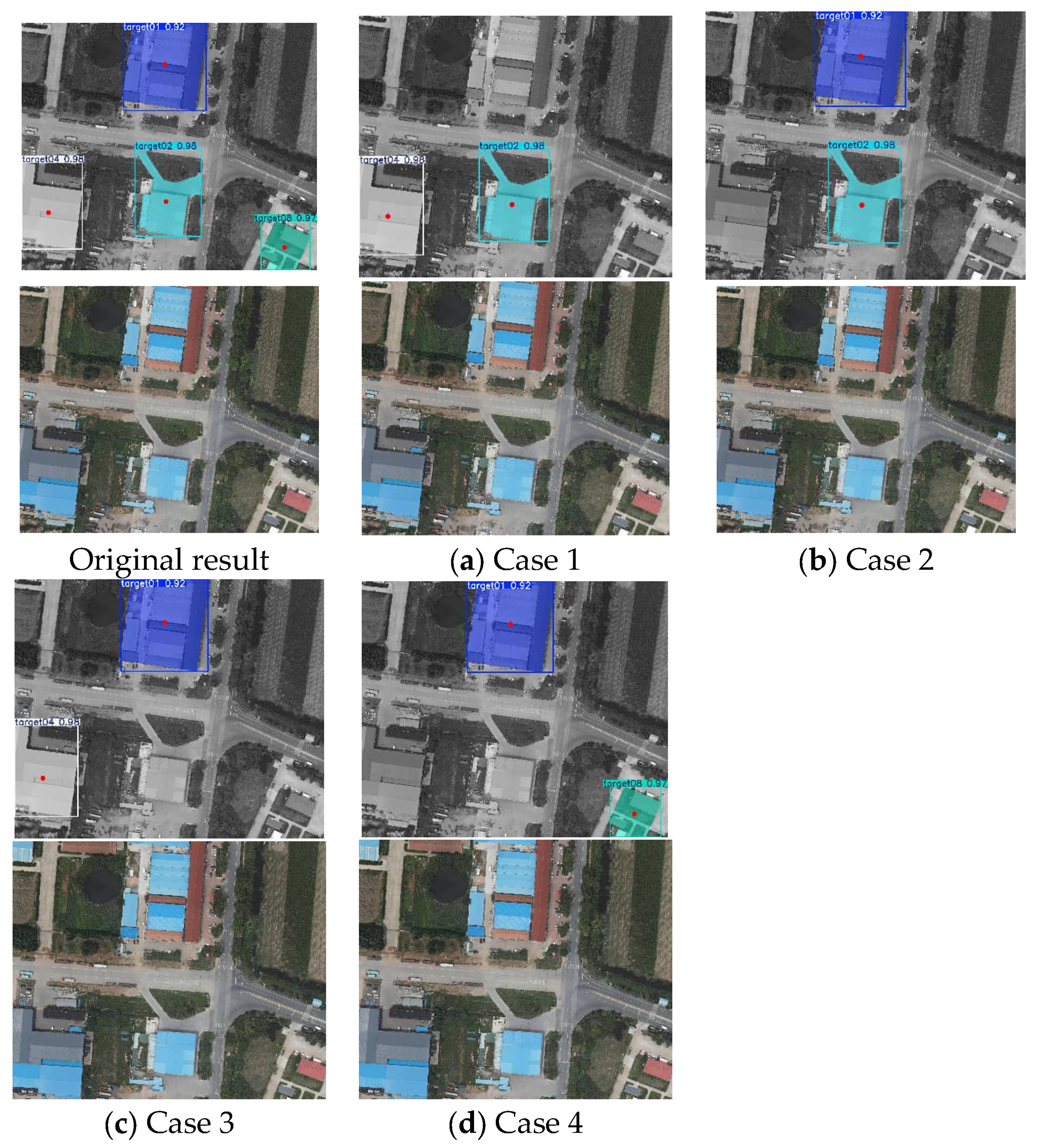
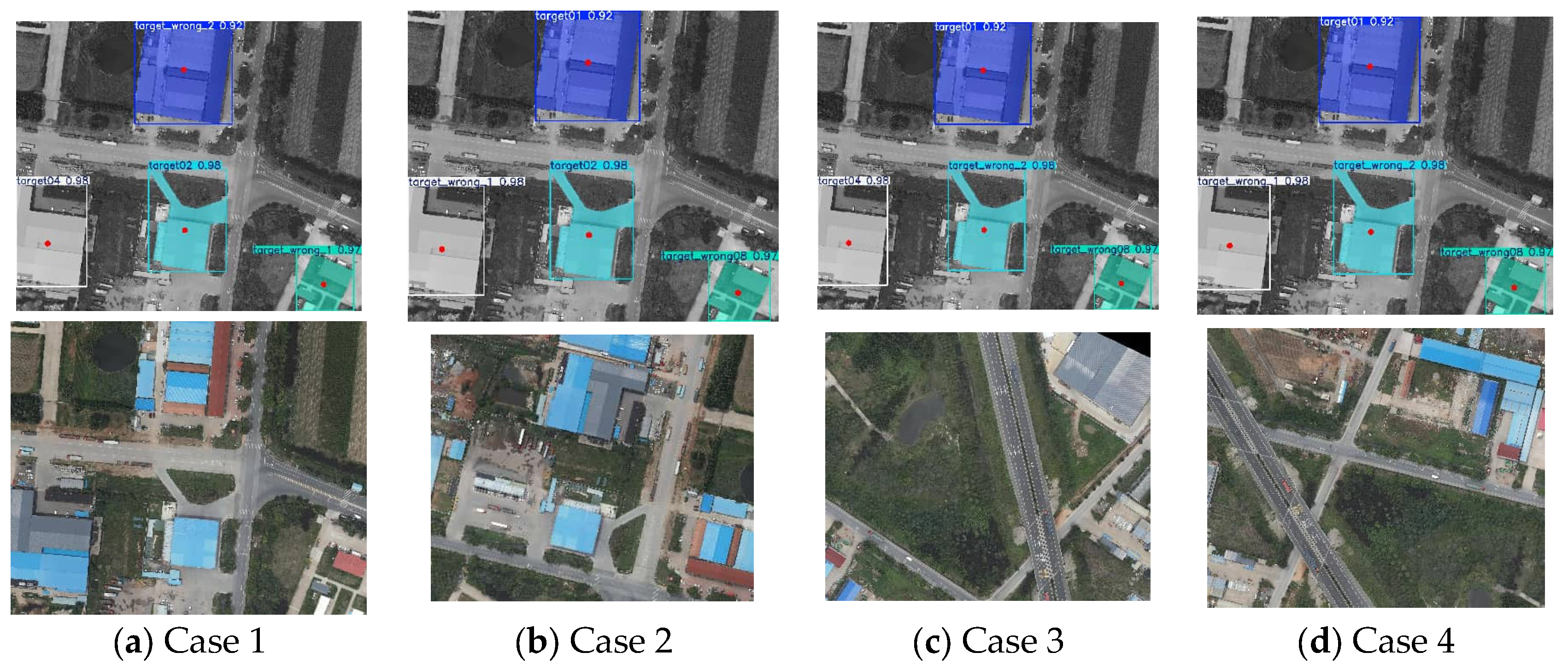
The results are shown in Figure 19.
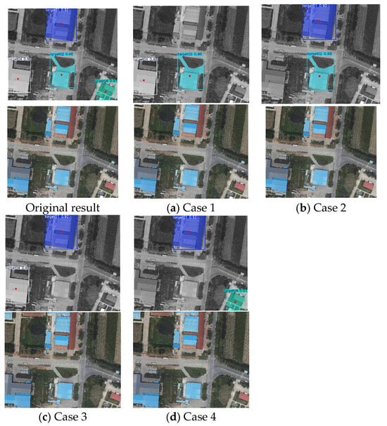
Figure 19.
Localization results when the number of instances is 2 or more.
As shown in Figure 19, target02 and target04 form semantic feature vectors, and the centroid of target02 is the feature center. If the remaining number of instances is 2 or more, missing instances will not have a significant impact on localization results. When the remaining number of instances is 1, the localization result is shown in Figure 20.
Figure 20.
Localization results when the number of instances is 1.
If the remaining number of instances is 1, it will cause significant changes in the localization region. When the remaining number of instances is 0, it fails to locate UAVs.
- (2)
- Localization results under false detection conditions.
False detection conditions can be divided into four conditions:
- (a)
- The feature vector contains no false detection instances.
- (b)
- The feature vector contains one false detection semantic instance that is not the feature center.
- (c)
- The feature vector contains one false detection semantic instance that serves as the feature center.
- (d)
- The feature vector contains two false detection semantic instances.
Clearly, (a) has no impact on localization, while (d) leads to failure to localize. The localization results are shown in Figure 21.
Figure 21.
Localization results when the number of instances is 1.
As shown in Figure 21, when the false detected instance is in the feature vector but not at the feature center, it will result in an incorrect raw angle. When the false detection instance is the feature center, it will fail to locate UAVs.
In addition, the proposed method only needs to record the locations of unique semantic instances, resulting in a small data storage requirement and fast retrieval speed during matching. For a reference image of size 27,501 × 5701 pixels and 40 unique semantic instances, the database sizes constructed using Methods A, B, and the proposed method are 98.9 KB, 2.6 KB, and 1.2 KB. The retrieval times for Method A, Method B, and the proposed method are 0.532 ms, 0.058 ms, and 0.023 ms. The mean feature extraction time for Method A, Method B, and the proposed method are 3.724 ms, 3.657 ms, and 3.353 ms. However, the proposed method still has some limitations. First, when the number of semantic instances is one, the localization accuracy is lower compared to scenarios with more than two instances, and it cannot correct the yaw angle. Second, the method relies on the presence of unique semantic instances in the localization task scenario; if such instances are absent in the region, localization becomes difficult. Future research will focus on combining unique semantic instances with non-unique semantic instances to improve the method’s adaptability to various scenarios.
5. Conclusions
A UAV localization method based on unique semantic instances is proposed in this paper. The proposed method first extracts the categories of unique semantic instances from aerial images using YOLO26. These categories are then used to retrieve and match the corresponding feature vectors stored in the database. The location of the UAV is determined based on the centroid positions of the matched unique semantic instances stored in feature vectors. Experimental results show that the proposed method achieves a localization success rate exceeding 95% within the mission region and exhibits robustness to variations in the attitude and field of view of aerial images. The method is simpler and more stable by using unique semantic instances for localization. Furthermore, the use of unique semantic instances to construct feature vectors effectively reduces storage capacity requirements and improves matching efficiency. However, the proposed method still has some limitations. It relies on the presence of unique semantic instances. Future work will integrate unique semantic instances with non-unique semantic features to improve adaptability.
Author Contributions
Conceptualization, Q.Z. and Y.L.; methodology, Y.L.; software, Y.L.; validation, Q.Z., J.W. (Junjie Wu), Z.J., J.W. (Junwei Wan) and R.L.; data curation, J.W. (Junjie Wu) and Z.J.; writing—original draft preparation, Y.L.; writing—review and editing, Q.Z., J.W. (Junjie Wu), Z.J., J.W. (Junwei Wan) and R.L.; funding acquisition, R.L. All authors have read and agreed to the published version of the manuscript.
Funding
This research was funded by the National Natural Science Foundation of China, grant number 62273179.
Data Availability Statement
The data underlying the results presented in this paper are not publicly available at this time but may be obtained from the authors upon reasonable request.
Conflicts of Interest
The authors declare no conflicts of interest.
Abbreviations
The following abbreviations are used in this manuscript:
| AH-epipolar | Antisymmetric-Homography epipolar |
| EPNP | Efficient Perspective-n-Point |
| LETR | LinE segment TRansformers |
| LSD | Line Segment Detector |
| MLPnP | Maximum Likelihood Perspective-n-Point |
| ORB | Oriented FAST and Rotated BRIEF |
| SURF | Speeded Up Robust Features |
| SAM3 | Segment Anything Model 3 |
| UAV | Unmanned Aerial Vehicle |
| UPnP | Uncalibrated Perspective-n-Point |
| YOLO | You Only Look Once |
References
- Yadav, S.A.; Huang, Y.; Zhu, K.Q.; Haque, R.; Young, W.; Harvey, L.; Hall, M.; Zhang, X.; Wijewardane, N.K.; Qin, R.; et al. Deep Transfer Learning for UAV-Based Cross-Crop Yield Prediction in Root Crops. Remote Sens. 2025, 17, 4054. [Google Scholar] [CrossRef] [Scilit]
- Li, H.; Ma, J.; Zhang, J. ELNet: An Efficient and Lightweight Network for Small Object Detection in UAV Imagery. Remote Sens. 2025, 17, 2096. [Google Scholar] [CrossRef] [Scilit]
- Zhai, F.; Zeng, Q.; Li, J.; Jin, Z. Iterative Geolocation Based on Cross-View Image Registration (IGCIR) for Long-Range Targets. Chin. J. Aeronaut. 2025, 38, 103483. [Google Scholar] [CrossRef] [Scilit]
- Cheng, Z.; Gong, W.; Jaboyedoff, M.; Chen, J.; Derron, M.-H.; Zhao, F. Landslide Identification in UAV Images Through Recognition of Landslide Boundaries and Ground Surface Cracks. Remote Sens. 2025, 17, 1900. [Google Scholar] [CrossRef] [Scilit]
- Miao, Z.; Zhou, R.; Liu, J.; Yang, H. Research progress of absolute visual positioning for unmanned aerial vehicles. Chin. J. Liq. Cryst. Disp. 2025, 40, 942–955. [Google Scholar] [CrossRef] [Scilit]
- Bay, H.; Ess, A.; Tuytelaars, T.; Van Gool, L. Speeded-Up Robust Features (SURF). Comput. Vis. Image Underst. 2008, 110, 346–359. [Google Scholar] [CrossRef] [Scilit]
- Rublee, E.; Rabaud, K.; Bradski, G. ORB: An efficient alternative to SIFT or SURF. In Proceedings of the 2011 International Conference on Computer Vision, Barcelona, Spain, 6–13 November 2011. [Google Scholar]
- Von Gioi, R.G.; Jakubowicz, J.; Morel, J.-M.; Randall, G. LSD: A Fast Line Segment Detector with a False Detection Control. IEEE Trans. Pattern Anal. Mach. Intell. 2010, 32, 722–732. [Google Scholar] [CrossRef] [Scilit]
- DeTone, D.; Malisiewicz, T.; Rabinovich, A. SuperPoint: Self-Supervised Interest Point Detection and Description. In Proceedings of the IEEE Conference on Computer Vision and Pattern Recognition Workshops (CVPRW), Salt Lake City, UT, USA, 18–22 June 2018. [Google Scholar]
- Xu, Y.; Xu, W.; Cheung, D.; Tu, Z. Line Segment Detection Using Transformers Without Edges. In Proceedings of the 2021 IEEE/CVF Conference on Computer Vision and Pattern Recognition (CVPR 2021), Nashville, TN, USA, 19–25 June 2021. [Google Scholar]
- Sun, J.; Shen, Z.; Wang, Y.; Bao, H.; Zhou, X. LoFTR: Detector-Free Local Feature Matching with Transformers. In Proceedings of the 2021 IEEE/CVF Conference on Computer Vision and Pattern Recognition (CVPR), Nashville, TN, USA, 20–25 June 2021; IEEE: Piscataway, NJ, USA, 2021. [Google Scholar]
- Wang, H.; Zhou, F.; Wu, Q. Accurate Vision-Enabled UAV Location Using Feature-Enhanced Transformer-Driven Image Matching. IEEE Trans. Instrum. Meas. 2024, 73, 5502511. [Google Scholar] [CrossRef] [Scilit]
- Li, Y.; Zeng, Q.; Jin, Z.; An, Y.; Li, R. Monocular Visual Localization Method Based on Antisymmetric-Homography Epipolar Constraint Theory. Measurement 2026, 266, 120502. [Google Scholar] [CrossRef] [Scilit]
- Lepetit, V.; Moreno-Noguer, F.; Fua, P. EPnP: An Accurate O(n) Solution to the PnP Problem. Int. J. Comput. Vis. 2009, 81, 155–166. [Google Scholar] [CrossRef] [Scilit]
- Kneip, L.; Li, H.; Seo, Y. UPnP: An optimal O(n) solution to the absolute pose problem with universal applicability. In Proceedings of the European Conference on Computer Vision (ECCV), Zurich, Switzerland, 6–12 September 2014. [Google Scholar]
- Urban, S.; Leitloff, J.; Hinz, S. MLPnP—A Real-Time Maximum Likelihood Solution to the Perspective-n-Point Problem. Remote Sens. Spat. Inf. Sci. 2016, 3, 131–138. [Google Scholar] [CrossRef] [Scilit]
- Kusumaningrum, R.; Arymurthy, A.M. Color and texture feature for remote sensing-image retrieval system: A comparative study. Int. J. Comput. Sci. Issues (IJCSI) 2011, 8, 125. [Google Scholar]
- Ömrüuzun, F.; Yardımcı Çetin, Y.; Leloğlu, U.M.; Demir, B. A Novel Semantic Content-Based Retrieval System for Hyperspectral Remote Sensing Imagery. Remote Sens. 2024, 16, 1462. [Google Scholar] [CrossRef] [Scilit]
- Lin, Z.; Zhu, F.; Kong, Y.; Wang, Q.; Wang, J. SRSG and S2SG: A Model and a Dataset for Scene Graph Generation of Remote Sensing Images from Segmentation Results. IEEE Trans. Geosci. Remote Sens. 2022, 60, 4707411. [Google Scholar] [CrossRef] [Scilit]
- Shi, Q.; Lan, C.; Xu, Q. Evaluation and analysis of deep learning global representation model for satellite remote sensing image retrieval and location. J. Geo-Inf. Sci. 2022, 24, 2245–2263. [Google Scholar] [CrossRef]
- Zhuo, Z.; Zhou, Z. Remote Sensing Image Retrieval with Gabor-CA-ResNet and Split-Based Deep Feature Transform Network. Remote Sens. 2021, 13, 869. [Google Scholar] [CrossRef] [Scilit]
- Shan, X.; Liu, P.; Gou, G.; Zhou, Q.; Wang, Z. Deep Hash Remote Sensing Image Retrieval with Hard Probability Sampling. Remote Sens. 2020, 12, 2789. [Google Scholar] [CrossRef] [Scilit]
- Buck, A.R.; Keller, J.M.; Skubic, M. A Modified Genetic Algorithm for Matching Building Sets with the Histograms of Forces. In Proceedings of the IEEE Congress on Evolutionary Computation, Barcelona, Spain, 18–23 July 2010. [Google Scholar]
- Wang, M.; Chang, X.; Sun, K.; Chen, J.; Sun, F.; Liu, Y.; Wang, G.; Zhang, M. A Road Intersection Matching Method Based on Triangular Structure. In Proceedings of the 2024 4th International Conference on Advanced Algorithms and Neural Networks (AANN 2024), Qingdao, China, 9–11 November 2024. [Google Scholar]
- Schmidt, R.; Rüter, J.; Krause, S.; Schubert, S. Vision-Based Self-Localization for UAVs Using Semantic Features and OpenStreetMap. In Proceedings of the 2025 IEEE Aerospace Conference, Big Sky, MT, USA, 1–8 March 2025. [Google Scholar]
- Li, Y.; Zeng, Q.; Jin, Z.; Hong, S.; Li, B.; Sun, X. Research on Rough Scene Matching Navigation Method Based on Semantic Bag of Words Model. In Proceedings of the 2023 7th International Symposium on Computer Science and Intelligent Control (ISCSIC), Nanjing, China, 27–29 October 2023. [Google Scholar]
- He, J.; Wu, Q. A Localization Method for UAV Aerial Images Based on Semantic Topological Feature Matching. Remote Sens. 2025, 17, 1671. [Google Scholar] [CrossRef] [Scilit]
- Tang, J.; Tong, X.; Qiu, C.; Lei, Y.; Yi, L.; Song, H. Remote sensing scene retrieval method based on scene graph. Acta Geod. Et Cartogr. Sin. 2025, 54, 123–135. [Google Scholar] [CrossRef]
- Zhou, Q.; Tang, H.; Zhang, Z.; Xu, Y.; Xiao, F.; Jia, Y. A Hierarchical Absolute Visual Localization System for Low-Altitude Drones in GNSS-Denied Environments. Remote Sens. 2025, 17, 3470. [Google Scholar] [CrossRef] [Scilit]
- Ye, Q.; Luo, J.; Lin, Y. A Coarse-to-Fine Visual Geo-Localization Method for GNSS-Denied UAV with Oblique-View Imagery. ISPRS J. Photogramm. Remote Sens. 2024, 212, 306–322. [Google Scholar] [CrossRef] [Scilit]
- Liu, H.; Liu, R.; Tan, W.; Jia, R.; Li, T. A Coarse-to-Fine Localization Algorithm for UAVs Based on Heterogeneous Image Matching. IEEE Trans. Aerosp. Electron. Syst. 2026, 62, 335–349. [Google Scholar] [CrossRef] [Scilit]
- Ye, J.; Lin, H.; Ou, L.; Chen, D.; Wang, Z.; Zhu, Q.; He, C.; Li, W. Where Am I? Cross-View Geo-Localization with Natural Language Descriptions. In Proceedings of the 2025 IEEE/CVF International Conference on Computer Vision (ICCV 2025), Honolulu, HI, USA, 19–23 October 2025. [Google Scholar]
- Jocher, G.; Qiu, J. Ultralytics Yolo26 2026. Available online: https://github.com/ultralytics/ultralytics (accessed on 22 December 2025).
- Kirillov, A.; Mintun, E.; Ravi, N.; Mao, H.; Rolland, C.; Gustafson, L.; Xiao, T.; Whitehead, S.; Berg, A.C.; Lo, W.-Y.; et al. Segment Anything. arXiv 2023, arXiv:2304.02643. [Google Scholar]
- Rehder, J.; Nikolic, J.; Schneider, T.; Hinzmann, T.; Siegwart, R. Extending Kalibr: Calibrating the Extrinsics of Multiple IMUs and of Individual Axes. In Proceedings of the 2016 IEEE International Conference on Robotics and Automation (ICRA), Stockholm, Sweden, 16–21 May 2016. [Google Scholar]

Disclaimer/Publisher’s Note: The statements, opinions and data contained in all publications are solely those of the individual author(s) and contributor(s) and not of MDPI and/or the editor(s). MDPI and/or the editor(s) disclaim responsibility for any injury to people or property resulting from any ideas, methods, instructions or products referred to in the content. |
© 2026 by the authors. Licensee MDPI, Basel, Switzerland. This article is an open access article distributed under the terms and conditions of the Creative Commons Attribution (CC BY) license.