


Abstract
The increasing integration of intermittent renewable energy sources (RESs) into islanded Hybrid Power Systems (HPSs) is a critical step towards global energy sustainability; however, it poses significant challenges to frequency stability owing to low system inertia and stochastic power fluctuations. To address these challenges and enable higher penetration of green energy, this study proposes a novel and robust Load Frequency Control (LFC) strategy based on the Crested Porcupine Optimizer (CPO). A customized Mode-Dependent Adaptive Balloon (MDAB) controller is developed, wherein the virtual control gain is dynamically tuned based on the real-time operating modes and disturbance severity. Furthermore, to optimize communication resources and mitigate actuator wear in networked microgrids, an intelligent event-triggered (ET) mechanism is seamlessly integrated into the adaptive logic. The proposed control framework is rigorously validated through comprehensive nonlinear simulations and comparative analyses with state-of-the-art metaheuristic algorithms (GTO, GWO, JAYA, and GO). The evaluation encompasses step load disturbances, severe parametric uncertainties (+25%), realistic 24-h diurnal cycles with solar cloud shading and wind turbulence, and extended practical constraints, including Battery Energy Storage System (BESS) integration and Internet of Things (IoT) communication delays. The results demonstrate the superiority of the CPO-tuned framework, which achieved the fastest transient recovery (settling time of 3.4367 s) and the lowest absolute Integral Absolute Error (IAE). Additionally, the proposed ET-based strategy not only reduced the communication burden but also improved the overall control performance by 37% in terms of IAE compared with continuous approaches. By inherently filtering measurement noise, mitigating control signal chattering, and maintaining resilience under nonideal latency, the proposed architecture offers a highly robust and resource-efficient solution that directly guarantees the operational sustainability and reliability of modern smart microgrids.
1. Introduction
Decentralized power generation has become more prevalent in the global energy paradigm in recent decades as a fundamental driver for achieving environmental sustainability and supplying the growing demand for clean energy (aligning directly with the United Nations Sustainable Development Goal 7: Affordable and Clean Energy).
To provide a broader context for unfamiliar readers, it is important to note that modern sustainable microgrids are evolving into highly interactive entities. They often operate within complex frameworks involving multi-level energy trading and optimized bidirectional time-of-use pricing strategies in multi-microgrid configurations [1]. The integration of such advanced economic and operational strategies makes maintaining dynamic stability more challenging. When active power deficits occur due to severe disturbances or high renewable intermittency, the system frequency can drop significantly. In extreme emergency cases, preserving sustainable system integrity necessitates comprehensive measures such as integrated underfrequency load shedding strategies that effectively account for multiclass load-related factors [2]. While these emergency load shedding protocols are crucial for preventing total blackouts, the primary and secondary Load Frequency Control (LFC) systems act as the continuous, first line of defense to seamlessly regulate minor and moderate power imbalances without disconnecting consumers.
Microgrids (MGs) and hybrid power systems (HPSs), which integrate various renewable energy sources (RESs), have become essential solutions [3] like photovoltaic (PV) arrays, wind turbine generators (WTGs), and fuel cells. These MGs work in an islanded mode, which means they can provide power to remote areas without relying on the main utility grid. But the fact that inverter-based RESs are so common makes stability very difficult. Power electronic converters don’t have physical inertia like traditional synchronous generators do, which have a lot of rotating mass [4]. This “low inertia” feature makes the system very sensitive to power imbalances, which can cause quick and large frequency changes that can cause cascade failures or blackouts [5]. As a result, making sure that low-inertia islanded MGs have stable frequencies has become a very important area of research [6,7]. Furthermore, in highly renewable islanded hybrid systems, frequency stability is strictly coupled with voltage and current dynamics during severe disturbances. Such systems often exhibit weak grid characteristics, including large impedances and sudden phase angle differences, which lead to transient current shocks that complicate stabilization. Advanced techniques, such as self-synchronizing voltage source control and transient/steady-state impedance reshaping, have been shown to effectively resolve these voltage-current balancing issues (e.g., low-voltage ride-through [8]. Addressing these coupled dynamics contextualizes the severe challenges of transient stability in low-inertia microgrids, thereby justifying the critical need for the adaptive robust control framework proposed in this study.
Load Frequency Control (LFC) loops are used to keep the balance between power generation and load demand. The main goal of LFC is to reduce frequency oscillations and bring the frequency back to its normal value after a disturbance [9]. Proportional-Integral-Derivative (PID) controllers and their variants (PI, PIDF) have been the industry standard for a long time because they are easy to use and have a simple structure [10]. However, these classical controllers are usually set up to work at a certain point using linearized models. Because modern HPSs are very nonlinear and random and change over time (because of changes in wind speed and solar irradiance), fixed-gain PID controllers often don’t provide enough damping in a wide range of operating conditions [11]. This constraint compels the formulation of more adaptive and resilient control strategies adept at managing parametric uncertainties and significant disturbances [12,13].
Researchers have thoroughly examined the use of metaheuristic optimization algorithms to solve the tuning problems of classical controllers. These bio-inspired methods use natural events to find the best possible settings for controller parameters [14,15]. Many algorithms have been successfully used on LFC in the past few years. Some of the most well-known ones are the Genetic Algorithm (GA), Firefly Algorithm (FA), and Particle Swarm Optimization (PSO) [16,17,18]. Recently, algorithms [19] like the Grey Wolf Optimizer (GWO) [20], Whale Optimization Algorithm (WOA) [21], Multi-Verse Optimizer (MVO) [22], JAYA algorithm [23], Gorilla Troops Optimizer (GTO) [24], and Growth Optimizer (GO) [25] have become very popular for LFC tasks because they converge better. Moreover, the versatility of these heuristic algorithms is increasingly evident in fully inverter-dominated grids. For instance, in Virtual Synchronous Generator (VSG)-only networks—which replace traditional synchronous machines and face analogous low-inertia and transient oscillation challenges—recent studies demonstrate that advanced metaheuristics, such as Crisscross Optimization, can dynamically optimize system virtual inertia. This dynamic tuning significantly reduces post-disturbance oscillation amplitudes and settling times [26]. Discussing these emerging VSG-dominated system optimizations reflects the broader capability of heuristic methods in solving complex low-inertia stability problems, thereby highlighting the significance of deploying advanced algorithms like the proposed CPO. Nonetheless, despite their enhanced efficacy relative to conventional trial-and-error or Ziegler–Nichols techniques, these contemporary optimizers may still experience premature convergence or stagnation in local optima, especially within the high-dimensional search spaces of intricate hybrid MGs [27].
To overcome these limitations, advanced optimization algorithms equipped with rigorous mechanisms for escaping local optima are critically required. Consequently, the recently developed Crested Porcupine Optimizer (CPO) is adopted in this study. Unlike conventional algorithms that often struggle to maintain population diversity (e.g., PSO) or suffer from reduced exploitation efficiency in their later stages (e.g., GWO), CPO employs a unique multi-strategy search mechanism. By mathematically mimicking the visual, acoustic, and physical defense behaviors of crested porcupines, CPO dynamically shifts between different adaptive phases. This multi-phase approach provides a better balance between wide-area exploration and precise exploitation, which helps reduce the probability of local optima entrapment. To clearly articulate this research gap and justify the proposed approach, Table 1 presents a comparative summary of modern frequency control tuning methods and their respective limitations.
Beyond optimization challenges, most current LFC studies still use the idea of “Time-Triggered” communication, which means that control signals are sent all the time at every sampling instant [28]. This is despite the fact that control tuning has come a long way. In real-world networked control systems, communication bandwidth is a limited resource. Continuous data transmission not only causes network congestion and possible packet dropouts, but it also causes unnecessary wear and tear on the actuators (like governor valves) because of high-frequency chattering [29]. This problem is made worse in MGs that don’t have a lot of ways to communicate. Event-Triggered (ET) control schemes have been put in place as a more efficient way to deal with these problems. ET control greatly lessens the communication load by transmitting signals only when predefined conditions are violated [30], while recent studies have further enhanced this concept using adaptive event-triggering mechanisms to improve flexibility and efficiency.
Table 1.
Comparative analysis of modern LFC tuning methods in microgrids.
While recent studies have employed adaptive thresholds informed by error magnitude or channel traffic [32,33,34], the creation of a context-aware mechanism that dynamically modifies its threshold according to the system’s operational mode, such as differentiating between steady-state and emergency recovery, is still an inadequately investigated domain in the literature.
Furthermore, regarding optimization, most existing metaheuristic-based LFC studies focus on optimizing fixed controller parameters under predefined operating conditions. As a result, these statically tuned approaches lack the ability to adapt dynamically when the microgrid transitions between significantly different physical operating modes (e.g., diesel-dominated emergency recovery versus aggressive PV ramping). Accordingly, bridging the gap between static offline metaheuristic optimization and real-time adaptive control under multi-mode operation remains a critical unaddressed challenge. Motivated by the aforementioned challenges and the critical need for robust frequency regulation in low-inertia MGs, this paper proposes a novel, adaptive control framework designed to handle severe stochastic fluctuations. The proposed strategy integrates the CPO, a recently developed metaheuristic algorithm known for its superior exploration-exploitation balance, with a novel Mode-Dependent Event-Triggered Adaptive Balloon (MDET-AB) controller. Unlike conventional fixed-structure controllers, the proposed logic mimics the physical behavior of a balloon to dynamically adjust the system’s virtual gain based on the real-time operating mode, considering load recovery, steady wind, or aggressive PV. This integration makes sure that the control effort is strong enough during important disturbances and weak enough during steady states, all while dealing with communication problems at the same time. The main new ideas and contributions of this study are summed up as follows:
- By enhancing frequency stability and drastically reducing mechanical wear on physical assets, the proposed framework directly contributes to the economic and environmental sustainability of autonomous microgrids, thereby enabling safer, higher penetrations of intermittent green energy.
- A novel application of CPO is introduced for the optimal tuning of LFC parameters within an islanded HPS, demonstrating superior convergence speed and solution quality compared to established bio-inspired algorithms.
- A new adaptive control logic is introduced that adjusts controller gains for ‘Balloon Inflation/Deflation’ based on system modes, including recovery, steady wind, and PV, enabling context-aware frequency regulation.
- An intelligent ET mechanism enhances control loop efficiency by balancing performance and communication network use, reducing control signal transmission while maintaining stability.
- The proposed framework is validated under a realistic 24-h variable generation/load profile and demonstrates robustness through extensive sensitivity analysis against parametric uncertainties.
2. System Modeling and Dynamic Architecture
In this study, an Islanded HPS (IHPS) is developed to evaluate the effectiveness and resilience of a specific control methodology. The system combines a Diesel Engine Generator (DEG) with RESs, namely PV arrays and WTG, to enhance reliability. While renewable sources are crucial for reducing carbon emissions, their inherent variability presents challenges in maintaining stable power frequency [35]. As a result, linearized first-order transfer functions appropriate for small-signal stability analysis are used to describe the dynamic behavior of each component. It is important to articulate the assumptions underlying this mathematical approximation: LFC fundamentally deals with small-signal perturbations (e.g., marginal changes in load or weather conditions) to regulate frequency within tightly constrained limits. Within this narrow operational bandwidth, dominant nonlinear effects (such as complex combustion dynamics) are not significantly excited, making linearized models both accurate and computationally efficient [36]. Nevertheless, to ensure the simulation rigorously reflects real-world mechanical constraints and avoids overly optimistic controller performance, critical physical non-linearities—specifically the Generation Rate Constraint (GRC) and Governor Dead Band (GDB)—are explicitly retained and integrated into the DEG model. This modeling approach is crucial to simulating the rapid disturbances that the proposed Mode-Dependent Adaptive Balloon (MDAB) controller is designed to mitigate. The DEG is utilized primarily as a backup inertia provider and to compensate for the power deficit during periods of low renewable availability or sudden load perturbations.
The fundamental principle governing the system’s frequency response is the balance between total power generation and load demand. The net power deviation error , which drives the frequency deviation can be mathematically formulated as the algebraic sum of the individual power outputs minus the load disturbance, as expressed in (1):
where and represent the power deviations from the photovoltaic and wind systems, respectively. denotes the controlled power output from the diesel generator. is the perturbation in the load demand.
The dynamic characteristics and mathematical formulation of these subsystems are detailed in the following subsections, followed by the aggregate power system model.
2.1. PV System Model
The power output of the PV array is intermittent and highly dependent on environmental factors, specifically solar irradiance and ambient temperature. The mathematical model governing the output power is expressed as [37]:
where is the conversion efficiency of the PV panel; is the solar irradiance ; is the effective area of the panel ; is the temperature coefficient; and are the ambient and reference temperatures, respectively.
To integrate this into the LFC model, the output is treated as a disturbance source, represented by the deviation . However, relying solely on static environmental parameters is insufficient for analyzing frequency stability. To evaluate the proposed controller’s robustness against realistic fluctuations, power variations caused by non-uniform irradiance and shading must be considered. Therefore, a band-limited white noise block is implemented within the MATLAB/Simulink R2023a environment to simulate real-life stochastic power swings. The PV power fluctuation is modeled as a combination of deterministic and stochastic components. The stochastic variation is represented by band-limited white noise filtered through a first-order low-pass system to reflect realistic, non-instantaneous environmental changes. The specific variance and power spectral density of this white noise block are not chosen arbitrarily; rather, they are calibrated based on typical meteorological data to simulate severe but realistic solar irradiance fluctuations (typically short-term fluctuations in the range of 10–20% around the nominal operating capacity due to fast-moving cloud transients) [38]. This calibration enables the injected stochastic noise to rigorously evaluate the controller’s robustness against practical weather intermittency. The resulting dynamic deviation in the PV output is expressed as a function of the square root of the nominal solar capacity , capturing both the physical dependency and realistic fluctuations. Based on the structural implementation depicted in Figure 1a, the mathematical expression is defined as [38]:
where denotes the filtered band-limited white noise.
Figure 1.
Comprehensive dynamic modeling of the proposed Islanded Hybrid Power System (IHPS): (a) PV stochastic fluctuation model; (b) WTG dynamic model with pitch control; (c) DEG dynamic model incorporating GRC and GDB constraints; and (d) Aggregate system architecture integrating the adaptive control framework. The solid arrows represent signal flow paths. In section (d), the large dashed box delineates the proposed integrated control unit, while the curved dashed arrows indicate the primary and secondary control loops. Different box colors are used to visually distinguish between distinct generation units and control elements.
Subsequently, to accurately reflect the physical dynamics of the grid connection, this raw power must pass through the PV inverter before being injected into the microgrid. The inverter is mathematically modeled as a first-order lag transfer function with a time constant , representing the inherent delays in power electronic switching and control processing. The final active power deviation injected into the microgrid plant, denoted as , is the filtered output of this inverter block. It should be noted that all variables in this mathematical formulation are expressed in the per-unit (p.u.) system to ensure dimensional consistency. The LFC system is evaluated using this comprehensive stochastic model under realistic noise and physical constraints, resulting in a PV power deviation profile that illustrates typical variations during the simulation period, as shown in Figure 2.
Figure 2.
Hourly PV power deviation under varying solar irradiance.
2.2. WTG Dynamic Modeling
The WT’s mechanical power is nonlinear, varying with wind speed cubically. For the analysis of LFC and small-signal stability, this study employs a comprehensive model that includes the dynamics of the hydraulic pitch actuator, blade characteristics, and fluid coupling interaction, illustrated in a detailed block diagram in Figure 1b.
The deviation in the generated wind power is dynamically coupled with the system frequency deviation. This relationship is governed by the fluid coupling gain and the difference between the turbine speed frequency and the system frequency , formulated as [39]:
To accurately represent the turbine’s internal dynamics, the turbine frequency deviation ) is modeled as a first-order lag function derived from the mechanical torque balance. This involves the interplay between pitch control feedback, wind power disturbance , and the blade characteristics, as expressed in [39]:
The dynamics of the pitch mechanism are modeled through a cascade of transfer functions representing the pitch controller, the hydraulic actuator, and the blade response , respectively [39]:
where the system parameters are defined as follows: is the turbine speed time constant; are the gains for blade characteristics and turbine power; are the gains associated with the pitch control loop, hydraulic actuator, and data-fit response; and are the corresponding time constants for the pitch control stages.
2.3. DEG Dynamic Modeling
In the proposed IHPS, the DEG functions as the primary dispatchable power source. Unlike the stochastic nature of PV and Wind subsystems, the DEG provides the essential rotational inertia and backup power required to maintain frequency stability during severe load perturbations or renewable generation deficits.
The dynamic response of the DEG is mechanically coupled to the fuel injection system and the combustion delay. For small-signal frequency analysis, the DEG model is decomposed into two cascaded stages: the speed governor and the diesel combustion turbine, as explicitly detailed in the simulation block diagram shown in Figure 1c [40].
2.3.1. Speed Governor Dynamics
The function of the speed governor is to regulate the fuel valve position in response to the frequency deviation signal and the controller command The governor is modeled as a first-order lag transfer function defined by a time constant , relating the change in valve position to the control input [40]:
where is the reference power setting provided from the proposed controller; is the speed regulation constant following the droop characteristic, which determines the steady-state frequency error; and represents the governor’s time constant.
2.3.2. Generator and Combustion Dynamics
The mechanical power produced by the diesel engine lags behind the fuel injection due to the combustion process and mechanical interactions [41]. This behavior is approximated by the generator’s transfer function with a characteristic time constant () [42]:
Combining the two stages, the overall transfer function relating the governor output to the generated electrical power deviation is expressed as [40]:
2.3.3. Handling Physical Non-Linearities
While Equations (9)–(11) describe the linear dynamics, realistic power systems are subject to physical constraints. As shown in the simulation block diagram (Figure 1c), the model explicitly incorporates the Generation Rate Constraint (GRC) and the Governor Dead Band (GDB). The GRC limits the rate of change in power output to prevent mechanical stress and model the thermodynamic limits of the engine. In this study, the GRC is set to () [43]. This ensures that the simulated frequency response accurately reflects real-world transient behavior.
Furthermore, the GDB nonlinearity is included to account for the inherent mechanical friction and backlash within the governor valve mechanism. Integrating these constraints ensures that the simulated frequency response accurately reflects real-world transient behavior and avoids overly optimistic controller performance.
2.3.4. Aggregate System Architecture
After modeling each subsystem (PV, Wind, and Diesel) in detail, the full structure of the proposed IHPS is put together. The total frequency deviation, ∆F, is caused by the difference between the total generation and load demand, considering the system’s inertia (H) and damping constant (D). The complete schematic diagram illustrating the interconnection between these renewable sources, the diesel generator, and the proposed control loops is depicted in Figure 1d, and the whole equation describes the system in Equation (12) [43].
3. Proposed Control Strategy
This section details the integrated control framework proposed in this study. The framework combines the robust search capability of the CPO algorithm with a novel ET adaptive balloon controller to achieve optimal frequency regulation with minimal communication overhead.
3.1. CPO
To optimize the control parameters of the Adaptive Balloon Controller for the islanded HPS, this study employs the CPO. The CPO is a novel nature-inspired metaheuristic algorithm proposed by Abdel-Basset et al. [31] Unlike many bio-inspired algorithms that simulate the predatory behaviors of carnivores, the CPO mimics the sophisticated defensive strategies of the crested porcupine (CP) when threatened. The algorithm is characterized by its ability to balance global exploration and local exploitation through four distinct defense mechanisms—sight, sound, odor, and physical attack—and a unique cyclic population reduction (CPR) technique as illustrated in the flowchart in Figure 3 [44,45].
Figure 3.
CPO flowchart showing the CPR and defense strategy phases [31]. The asterisk (*) in X_CP denotes the final optimal solution obtained by the algorithm.
3.1.1. CPR Technique
A distinctive feature of the CPO is the CPR mechanism. This strategy simulates the biological observation that not all members of a porcupine herd activate defense mechanisms simultaneously; rather, only those under direct threat react. Computationally, this serves to accelerate convergence by removing poor solutions and maintaining population diversity by periodically resetting the population size to avoid local optima. The population size N at iteration t is dynamically adjusted as [31]:
where is the initial population size; is the minimum population size; is the maximum number of iterations, and is the number of cycles.
3.1.2. Exploration Phase (Visual and Auditory Defense)
The exploration phase corresponds to the porcupine’s behavior when a predator is at a distance. Two strategies are employed:
- A.
- Visual Defense (First Strategy)
When a threat is detected visually, the CP erects its quills to appear larger. The predator may either approach or retreat. This behavior enables global exploration by moving the solution toward or away from the best solution . The position update is [31]:
where ; is a random number, and is a vector between the current CP and a randomly selected predator position.
- B.
- Sound Defense (Second Strategy)
If the visual deterrent fails, the CP produces rattling noises. This generates a probabilistic movement modeled using a binary vector [31]:
where , and are random indices from the population. This mechanism enables the exploration of new search regions.
3.1.3. Exploitation Phase (Olfactory and Physical Defense)
When the predator is in proximity, the CPO shifts to exploitation.
- A.
- Odor Defense (Third Strategy)
The CP releases a scent to repel the predator. The diffusion is modeled using a factor [31]:
where is a time-varying defense factor, and controls the search direction.
- B.
- Physical Attack (Fourth Strategy)
In critical proximity, the CP physically engages the predator. This is modeled as an inelastic one-dimensional collision [31]:
where is the convergence rate, and is the average collision force. This step ensures strong local convergence toward the global optimum.
3.2. Proposed Mode-Dependent CPO Modification
In the standard CPO, the change from exploration to exploitation is based only on random probabilities. Nonetheless, a significant contribution of this study is the establishment of a mode-dependent selection strategy. The probability of activating exploration mechanisms is dynamically skewed according to the recognized system mode. In Mode 3 (PV/Aggressive Mode), the algorithm makes its search space bigger when the solar irradiance changes quickly. This makes it easier to explore. The system goes to local exploitation to improve the current solution when Mode 2 is stable. This method links mathematical optimization directly to the grid’s actual state.
3.2.1. Proposed MDAB Logic
This study presents an innovative MDAB control technique to tackle the stochastic characteristics of RESs and abrupt load fluctuations. Unlike conventional fixed-structure controllers that rely on static gains, the MDAB mimics the physical behavior of a balloon—expanding (inflating) or contracting (deflating)—to effectively adjust the closed-loop system response based on the detected operating mode. This dynamic adaptation mechanism enables the controller to handle parameter uncertainties and external disturbances more effectively.
- A.
- Concept and Formulation
The core concept of the balloon effect is to introduce a virtual gain factor, termed the Air Level , which modifies the system’s apparent transfer function at each iteration This results in an adaptive closed-loop behavior that accounts for parameter uncertainties and external disturbances. The relationship between the input control signal and the system frequency deviation is defined as:
From a strict control theory perspective, the , parameter functions as a dynamic gain multiplier (or adaptive scaling factor). Physically, “inflation” (, >1) translates to an amplification of the controller’s gains () to deliver a highly aggressive control signal to the diesel governor’s valve actuator. Conversely, “deflation” (, <1) reduces these virtual gains, resulting in a softer mechanical control action that prevents actuator saturation and reduces wear. Therefore, the , parameter directly links the situational awareness of the microgrid to the physical actuation effort, as illustrated in Figure 4.
Figure 4.
Adaptive balloon effect with inflation (, >1) and deflation (, <1) mechanisms adjusting the system gain.
In the proposed MDAB, the transfer function is updated iteratively based on the previous state and the calculated Air Level
Substituting recursively, the instantaneous system model can be expressed relative to the nominal plant transfer function.
where represents the cumulative history of system variations, defined as:
It is important to clarify that this formulation does not physically alter the plant dynamics; rather, it represents an equivalent closed-loop scaling effect induced by the adaptive controller gains. In practice, the cumulative effect is strictly bounded by predefined limits on , ensuring numerical stability and preventing unbounded growth.
- B.
- Mode-Dependent Adaptation Strategy
The novelty of this study lies in governing the AL factor based on the active system mode (Recovery, Steady Wind, or Aggressive PV). Unlike traditional controllers that wait for a frequency drop (feedback) to react, the proposed switching logic utilizes direct power measurement variations (feedforward detection) to proactively transition between modes. This condition-monitoring mechanism operates continuously based on the following logic:
Mode 1 (Emergency Recovery): Initiated immediately when a load perturbation is detected ( > 0.001 p.u.). To ensure grid stability, the system locks into this recovery mode for a predefined duration (e.g., 8 s), allowing the diesel generator sufficient time to arrest the frequency drop and stabilize the microgrid.
Mode 3 (Aggressive PV): If no recent load events are detected, the system monitors the PV output. If solar generation is active and significant ( 0.01 p.u.), the controller switches to this mode to proactively counteract high-frequency solar intermittency.
Mode 2 (Steady State/Wind): This serves as the default operational state when there are no sudden load events and the PV generation is minimal or inactive, optimizing the control effort for steady wind variations.
Based on these identified modes, as depicted in the closed-loop control diagram in Figure 5, the MDAB logic adjusts the controller parameters limits and triggers the “inflation” or “deflation” of the control effort as follows:
Figure 5.
Proposed closed-loop control scheme featuring the MDAB logic.
- Case 1: Inflation (Active Recovery—Mode 1 & 3):
When the system detects a severe Load Step (Mode 1) or high PV fluctuations (Mode 3), the controller requires aggressive action. The MDAB sets (Balloon Inflation). This virtually amplifies the system gain, forcing the optimizer to generate a stronger control signal to suppress the frequency deviation rapidly. Furthermore, during Mode 1, the parameter bounds are expanded (e.g., upper bound = 40) to allow for this aggressive control, while in Mode 3, limits are specifically tuned to handle rapid transients.
- Case 2: Deflation (Steady State—Mode 2):
In Mode 2, when wind is stable, or there are only a few disturbances, high gains can cause oscillations that aren’t needed. In this case, the MDAB makes ALi ≤ 1 by applying the balloon deflation. This shrinks the virtual system model, which makes the control response smoother and more conservative to keep things stable. This adaptive mechanism makes sure that the suggested CPO-based controller doesn’t just optimize parameters for a static plant. It also works with a dynamic model that shows how bad the MG’s condition is at any given time.
It is worth noting that the predefined transition thresholds and duration periods are system-specific and were empirically tuned through extensive time-domain simulations to match the mechanical time constants of the DEG and avoid chattering.
3.2.2. Proposed Mode-Dependent Event-Triggered Mechanism (MDETM)
In conventional LFC systems, the control signal is sent out at regular intervals, no matter what the state of the system is. This constant transmission puts an extra strain on the communication network and causes the actuators of governor valves to wear out faster because of the high-frequency chattering. To solve this problem, this study suggests MDETM, which sends a new signal to the actuator only when certain stability-critical conditions are met. This cuts down on the number of times control updates need to be made. The proposed logic adds a dual-trigger condition to standard ET schemes that only use a fixed error threshold.
The first is the magnitude trigger, where a new control signal is sent out if the absolute difference between the last sent signal and the current calculated control effort calculated is greater than a certain value.
The second is the mode-switch trigger to make sure that the system can respond quickly to sudden changes; the transmission is forced right away whenever a change in the system’s operating mode is detected, even if it goes over the threshold. Mathematically, the transmission instant is determined by:
where is the time of the last successful transmission; is the current system mode identified by the detection logic; is the design threshold parameter, chosen to balance control performance and communication savings. If the condition is met, the actuator receives the new value: = , and the value is stored as . Otherwise, the actuator holds the previous value = , via a Zero-Order Hold (ZOH) unit, effectively silencing the communication channel during steady states. As explicitly depicted in the flowchart (Figure 6), this operational logic functions as a continuous real-time control loop. In practical hardware implementation, this loop operates indefinitely until a manual system shutdown or maintenance event occurs. However, for the scope of this algorithmic evaluation, the termination condition is strictly defined by the total simulation time . If this condition is not met, the algorithm systematically loops back to process the next sample. This dual-triggering formulation seamlessly guarantees that the control loop maintains rapid responsiveness to critical mode transitions while simultaneously maximizing communication efficiency.
Figure 6.
Proposed MDETM with dual-triggering conditions for mode and signal magnitude.
3.3. Optimization Problem Formulation and Performance Metrics
In order to fine-tune the proposed control strategy and compare its performance to existing methods in a strict way, the problem formulation is split into two parts: the online training stage, which uses a new analytical fitness function, and the offline testing stage, which uses standard error integral metrics.
3.3.1. Proposed Analytical Fitness Function (Training Stage)
This study uses a computationally efficient Analytical Objective Function (J) instead of traditional optimization methods that rely on time-consuming time-domain simulations (e.g., minimizing ITAE) during the search process. While the isolated power system (the plant) is modeled as a first-order inertial link in Equation (12), the introduction of the integral control action () in the secondary LFC loop increases the system type. Consequently, the overall closed-loop transfer function forms a standard second-order characteristic equation. This mathematical approximation allows the CPO to rapidly evaluate thousands of possible solutions analytically without executing a full dynamic simulation for each particle.
At each iteration, the damping ratio ζ and natural frequency are calculated based on the system’s inertia (M), damping (D), droop (R), and the proposed Balloon Air Level (AL) scaling factor, formulated according to standard second-order system dynamics as follows [46]:
Using these parameters, we can figure out the theoretical transient performance indices—Maximum Overshoot (Mp), Settling Time (Tss), and Rise Time (Tr)—to guess how stable the system will be [47]:
Finally, the proposed fitness function (J) is designed to minimize these indices at the same time, with a focus on response speed (Tr2) to make the controller more sensitive to changes:
The rationale behind formulating this composite objective function is grounded in the physical and operational requirements of LFC. Minimizing helps limit excessive transient deviations, thereby reducing the risk of triggering under-frequency load shedding (UFLS) mechanisms. Minimizing promotes rapid restoration of steady-state stability. Additionally, the rise time term is squared and weighted by to achieve a balanced trade-off between fast dynamic response and control smoothness. The weighting factor (0.5) was empirically selected to avoid overly aggressive control actions that could lead to actuator saturation or mechanical wear in the diesel governor. Ultimately, the CPO algorithm aims to minimize the composite objective function J, providing a strong indication of desirable transient stability characteristics prior to validation in the nonlinear simulation environment. (Note: The comprehensive configuration of the CPO hyperparameters—including the population size N = 30, maximum iterations = 100, and the randomized seed policy across 20 independent runs—is explicitly detailed in Section 4. These values were selected based on commonly adopted practices in the literature and validated through preliminary sensitivity testing.
3.3.2. Performance Evaluation Metrics (Assessment Stage)
After the optimization phase, MATLAB/Simulink R2023a’s detailed time-domain simulations are used to test the proposed controller’s robustness and efficiency. To make a fair comparison with the best algorithms and measure the quality of the control, the standard error integral indices are used [48]:
- Integral Absolute Error (IAE): This shows the total amount of error, which shows how well the system is damped.
- Integral Squared Error (ISE): Heavily punishes big mistakes, which shows that the controller can stop sudden peaks.
The simulation results show these metrics to back up the idea that the proposed strategy is better at minimizing errors and keeping track of trajectories.
3.3.3. Implementation of CPO for the Proposed LFC Framework
To clearly articulate the methodology of implementing the CPO algorithm for tuning the proposed LFC framework, the step-by-step execution process is established. In this implementation, each “Porcupine” (search agent) within the CPO population represents a candidate vector of the controller parameters (e.g., the integral gain ). The optimization process operates in a closed-loop fashion with the analytical microgrid model. First, the CPO initializes a population of random solutions within the mode-dependent search space boundaries. For each agent, the proposed analytical fitness function (J) is evaluated. Based on the fitness landscape, the CPO dynamically applies its Cyclic Population Reduction (CPR) and transitions between visual, auditory, olfactory, and physical defense strategies to update the position of each agent (controller gains). This iterative process continues until the maximum number of iterations is reached, yielding the optimal control parameters. The complete systematic implementation procedure, illustrating the interplay between the CPO, the MDAB controller, and the microgrid evaluation, is comprehensively depicted in the following flow diagram Figure 7.
Figure 7.
Flowchart illustrating the implementation procedure of the Crested Porcupine Optimizer (CPO) for tuning the proposed Mode-Dependent Adaptive Balloon (MDAB) controller within the LFC framework.
4. Results
In this section, the dynamic behavior and control performance of the studied IHPS are carefully simulated and analyzed using the MATLAB/Simulink R2023a environment. The system parameters are detailed in Table 2. Analytically, the investigated IHPS possesses a relatively low system inertia (M = 0.1667 p.u.s). This specific physical characteristic underscores the microgrid’s high vulnerability to rapid frequency deviations following generation-load mismatches, thereby strictly justifying the need for a highly responsive and adaptive control strategy. Meanwhile, the optimization settings are comprehensively outlined in Table 3. Table 3 explicitly reports the internal control parameters of the evaluated metaheuristic algorithms (CPO, GTO, GWO, JAYA, and GO), alongside the different search space boundaries for each operating mode, which makes the optimizer more responsive by using the proposed adaptive search strategy. From an analytical perspective, these mode-dependent search space boundaries play a pivotal role in regulating control aggressiveness. By dynamically restricting the optimizer’s exploration range based on the active operating mode, the controller physically prevents excessively aggressive signals during steady states while permitting rapid exploration during severe transients. As metaheuristic algorithms are quantitatively sensitive to parameter variations, modifying specific internal algorithmic weights (e.g., the convergence constant in GWO or in GO) can drastically shift the balance between local exploitation and global exploration, thereby affecting the final optimal solution. While a detailed sensitivity analysis of these internal hyperparameters is beyond the scope of this work, we eliminated any subjective tuning bias by ensuring that all evaluated algorithms were executed using their optimal standard default parameters, as strictly recommended by their original authors. Furthermore, to guarantee a fair and unbiased comparative analysis, identical universal conditions (Population size N = 30, Maximum iterations = 100, objective function, and the exact same mode-dependent search space boundaries) were applied consistently across all optimizers. Notably, the JAYA algorithm is included as a benchmark due to its inherent parameter-less nature.
Table 2.
Nominal parameters of the investigated IHPS subsystems.
Table 3.
Optimization parameters and adaptive search space settings. (Note: The mode-dependent search space limits and balloon expansion limits were consistently applied to all evaluated algorithms to ensure a fair comparison).
The simulation study is divided into four distinct test cases designed to evaluate the system’s stability under varying operational conditions and parametric uncertainties. This distinction ensures that each test case clearly reflects both the physical operating condition and the corresponding evaluation objective. The evaluated test cases are defined as follows:
- Test Case 1: Step load disturbance under PV integration (Comparative Performance Analysis).
- Test Case 2: System parametric uncertainties (Robustness and Sensitivity Analysis).
- Test Case 3: Communication network constraints (Assessment of the ET Adaptive Balloon Strategy).
- Test Case 4: Realistic 24-h variable generation and load profile (Long-term Real-time Validation).
- Test Case 5: Extended Robustness Analysis under Practical Constraints (BESS and Communication Delay).
4.1. Test Case 1: Step Load Disturbance with PV Integration
In this test case, the proposed CPO controller’s strength is tested by a sudden change in load and the use of renewable energy. The WTG is connected to the system from the start (t = 0) and provides steady power. At t = 5 s, a step load disturbance of 0.02 p.u. is added. After that, the PV system is connected to the MG at t = 25 s. This adds realistic power fluctuations and tests the controller’s ability to handle renewable energy that isn’t always available.
Physically, when the 0.02 p.u. step load disturbance is introduced, it creates an instantaneous active power mismatch between the total generation and the connected load. Because the generation cannot change instantly, the kinetic energy stored in the rotating masses of the system (primarily the Diesel Engine Generator) is extracted to compensate for this power deficit, which leads to an immediate drop in the system frequency. This frequency deviation is continuously monitored and fed into the LFC loop. In response, the optimized controller acts rapidly by sending a corrective signal to the DEG governor to increase the valve position and, consequently, the mechanical power output. This dynamic compensation process continues until the generated power perfectly matches the new load demand, ultimately restoring the frequency deviation to zero and stabilizing the microgrid.
Figure 8 shows how the HPS responds to changes in frequency in this situation. Figure 9 shows a zoomed-in view of the transient behavior and damping speed during the first load step so that they are easier to see. To establish a standard baseline reference under identical simulation conditions, a conventional integral (I) controller (denoted as ‘convI’) is also included in the simulations. The parameters of this classical baseline were carefully tuned using conventional trial-and-error methods to yield the most stable nominal response, thereby ensuring a fair and representative comparison.
Figure 8.
Comparative frequency deviation response of the HPS under Test case 1, illustrating the system behavior during step load disturbance and subsequent PV integration fluctuations (0–60 s).
Figure 9.
Magnified view of the frequency response during the step load disturbance (t = 5 s), highlighting the superior transient recovery speed and reduced overshoot of the proposed CPO.
It is clear that the suggested CPO-based controller has better damping properties than the GTO, GWO, JAYA, and GO algorithms. After the load disturbance at t = 5 s, the CPO controller does a great job of reducing the frequency drop and getting the system back to steady state as quickly as possible (as shown in Figure 9). The CPO controller also keeps the frequency deviation within a narrow range during the big changes caused by the PV integration (after t = 25 s, as seen in Figure 8). Other algorithms, like GTO and GO, along with the conventional controller, on the other hand, show big oscillations and big overshoots.
Table 4 shows the results of the numerical performance evaluation. The quantitative metrics of the classical controller are explicitly provided alongside the metaheuristic algorithms to highlight the improvement. The results show that the CPO algorithm works best overall when it comes to reducing errors, lowering peaks, and speeding up responses. The CPO controller had the lowest IAE of 0.3077, which is much lower than GTO’s (1.2557) and GO’s (0.8257) error indices. The ISE for CPO is 0.0049, which shows that it can quickly reduce large errors.
Table 4.
Performance comparison of different algorithms for Test case 1.
The suggested CPO controller was very stable and quick to respond to changes. It was able to keep the maximum undershoot at −0.0249 p.u. and the maximum overshoot at 0.0227 p.u. The GTO algorithm had a high overshoot of 0.1083 p.u., so this was a big step up. The CPO algorithm also had the fastest recovery time, taking 3.4367 s to settle. GWO (5.1270 s) is the closest competitor, and GTO (8.4077 s) is much faster. The CPO controller offers the best protection for sensitive grid equipment because it has low peak deviations and a quick settling time. From an analytical perspective, the quantitative metrics presented in Table 4 effectively highlight the optimal trade-off achieved by the CPO between cumulative error minimization and dynamic control smoothness. Securing the absolute lowest IAE alongside the fastest settling time mathematically confirms that the proposed algorithm systematically mitigates prolonged oscillatory behavior compared to conventional and alternative metaheuristic control frameworks.
4.2. Test Case 2: Sensitivity Analysis (Robustness Test)
To validate the robustness of the proposed CPO controller against parametric uncertainties, a sensitivity analysis is conducted. In practical power systems, system parameters often vary due to aging, modeling errors, or changing operating conditions. Therefore, in this test case, the system parameters, specifically the time constants of the Diesel Governor , and the Power System , are increased by 25% from their nominal values.
The system is subjected to the same load disturbance of 0.02 p.u. at t = 5 s, utilizing the optimal control gains obtained in Test case 1 without re-tuning. This tests the controller’s ability to maintain stability even when the plant model differs from the design model.
The frequency response under parameter uncertainty (+25% variation) is depicted in Figure 10, and the corresponding performance indices are listed in Table 5. Analytically, these metrics explicitly validate the robustness of the proposed control architecture under parametric uncertainty. While the classical controller and other algorithms exhibit significant performance degradation due to the +25% plant–model mismatch, the CPO algorithm maintains tight frequency regulation, confirming its high resilience against modeling inaccuracies and system aging. As clearly observed in the figures and explicitly quantified in the table, the classical controller baseline suffers from severe deviations and sluggish recovery under parametric variations. The results provide compelling evidence of the superior robustness of the proposed CPO controller. Despite the significant mismatch in system parameters, the CPO algorithm maintained the best control quality, achieving the lowest IAE of 0.3039, which is highly superior to GTO’s deteriorated index of 1.2592 and GO’s index of 0.5953.
Figure 10.
Robustness analysis: Frequency deviation response under +25% variation in system time constants, with the same as test case 1.
Table 5.
Performance comparison of different algorithms for Test case 2.
Most notably, the CPO controller demonstrated exceptional agility in rejecting the disturbance. It restricted the maximum undershoot magnitude to 0.0266 p.u. Furthermore, the CPO controller maintained the lowest maximum overshoot (0.0236 p.u.), significantly outperforming other algorithms like JAYA, which suffered from a high overshoot of 0.0507 p.u. and persistent high-frequency oscillations. While JAYA appeared to offer a competitive ISE, it exhibited a much higher settling time compared to its nominal performance. This observation firmly validates that the CPO controller ensures a stable, rapid recovery and is the most robust choice, balancing minimal peak deviations with rapid restoration.
4.3. Test Case 3: Assessment of Proposed ET Adaptive Balloon Strategy
To assess the proposed ET strategy in realistic and intricate operational environments, a comprehensive simulation test case is executed over a period of 100 s. The WTG is connected to the system from the beginning (t = 0 s). The system is subjected to the following sequence of disturbances:
- t = 5 s: A step load disturbance of 0.02 p.u.
- t = 25 s–40 s: The PV system is connected and sends power with a changing profile. This makes the controller have to deal with changes in dynamic generation.
- t = 70 s: A sudden change in the Wind power output is made.
The comparative frequency deviation response is visualized in Figure 11, and the corresponding performance metrics between the Continuous Balloon-CPO and the proposed ET balloon-CPO are summarized in Table 6. Performance comparison of different algorithms for Test case 3 has been analyzed. From an analytical standpoint, the data in Table 5 mathematically validates the dual-objective efficacy of the Event-Triggered mechanism. By achieving lower error indices (IAE and ISE) and significantly reducing peak transient deviations, the ET strategy proves that strategically limiting control updates not only conserves communication bandwidth but intrinsically suppresses detrimental controller chattering.
Figure 11.
Frequency deviation comparison between Continuous and Event-Based Balloon CPO strategies under a combined disturbance test case (Load Step, PV Integration, and Wind Variation).
Table 6.
Performance comparison of different algorithms for Test case 3.
The results reveal that the event-based strategy not only reduced the communication burden but also enhanced the control performance. The event-based CPO had an IAE of 0.5025, which is a 24% improvement over the Continuous CPO’s 0.6607. The ISE also went down a lot, from 0.0197 to 0.0069.
This substantial performance improvement is attributed to the inherent filtering capability of the ET mechanism. The controller in the Continuous approach responds to every little bit of measurement noise and small change (especially during the Wind variation at t = 70 s), which causes too much control action (High Chattering). The ET strategy, on the other hand, only updates the control signal when significant predefined error thresholds are breached. This stops “over-reaction,” which makes the response smoother, cuts down on overshoot (0.0317 p.u. vs. 0.0622 p.u.), and makes the system more stable overall.
Further insight into the controller’s intelligent decision-making process is provided by analyzing the adaptive gain evolution and operating mode transitions.
4.3.1. Correlation Between Operating Modes and Disturbances
The Event-Based strategy demonstrates a dynamic correlation between the system’s state and the active control mode. As explicitly shown in Figure 12, the controller successfully identifies the nature of each disturbance:
Figure 12.
Adaptive response of the ET controller: Gain () trajectory correlated with the MG operating modes (Mode 1: Diesel, Mode 2: Wind, Mode 3: PV). The vertical dashed lines indicate the exact time instants of applied disturbances (t = 5 s, t = 25 s, t = 70 s). The solid blue line represents the dynamic Controller Gain corresponding to the left axis, while the dashed orange line illustrates the Active Mode corresponding to the right axis.
- At t = 5 s (Load Step): The sudden frequency dip triggers Mode 1 (Recovery Mode). Consequently, the adaptive mechanism rapidly increases the integral gain to a high value, ensuring a fast recovery and eliminating the steady-state error caused by the load addition.
- At t = 25 s (PV Integration): With the injection of fluctuating solar power, the system transitions to Mode 3 (PV Mode). In this mode, the controller adopts a more aggressive tuning strategy (utilizing a wider search range) to track the fast dynamics of the PV inverter.
- At t = 70 s (Wind Variation): The logic sees the secondary disturbance caused by the WT’s fluctuations and keeps the controller in the right high-response state to stop the oscillations.
4.3.2. Comparison of Gain Evolution
A thorough comparison of the Event-Based CPO’s gain evolution and the Continuous CPO’s gain evolution shows how effective the proposed strategy is.
In the Continuous case (Figure 13), the controller gain changes all the time and very quickly during the simulation, even when things are relatively stable. This “chattering” behavior shows that the controller is responding to small measurement noise, which makes the computer work harder than it needs to. The event-based response (Figure 12), on the other hand, has a clear “staircase-like” stability. The gain remains constant (held) during steady-state intervals and only updates when a significant event triggers the mechanism. This confirms that the proposed ET-CPO successfully filters out redundant updates while preserving the aggressive tuning capability exactly when it is needed, creating a perfect balance between control performance and communication efficiency.
Figure 13.
Variation in the controller integral gain () under the continuous strategy, illustrating excessive chattering due to the absence of an event-triggering mechanism. The vertical dashed lines indicate the exact time instants of applied disturbances (t = 5 s, t = 25 s, t = 70 s).
4.4. Test Case 4: Real-Time 24-h Operation Profile
To validate that the proposed event-based balloon-CPO strategy is practical and robust, a full-day operation test case is conducted. The simulation time is scaled to 300 s to represent a complete 24-h diurnal cycle. This test case incorporates complex interactions between generation sources and variable load demand, which is designed to test the controller’s decision-making logic under stress.
4.4.1. Test Case Configuration
The system is subjected to a sequence of realistic events as illustrated in the simulation timeline:
- Solar Irradiance: Modeled as a Gaussian profile to mimic the sun’s trajectory, as shown in (Figure 14). At t = 75 s, the sun rises, which means it is at its brightest at noon (t = 150 s) and sets at t = 225 s. At t = 160 s, a sudden cloud shading effect is added, which makes PV generation drop quickly to see how quickly the controller can respond.
- Wind Profile: The wind speed varies dynamically, shifting from a moderate breeze (0.3 p.u.) in the early hours to high-turbulence gusts (0.5 p.u.) during the midday period (t = 100 s–200 s).
- Load Variations: Critical load events are applied to challenge the system stability:
- -
- Morning Peak (t = 40 s): A step load increase of 0.03 p.u. occurs when only Wind and Diesel are active.
- -
- Noon Peak (t = 150 s): A significant load addition of 0.04 p.u. coincides exactly with the maximum PV generation, creating a high-stress “Peak-on-Peak” condition.
- -
- Evening Drop (t = 230 s): A sudden load rejection of −0.05 p.u. occurs immediately after sunset.
Figure 14.
Simulated PV power generation in test case 4.
4.4.2. Performance Analysis and Comparative Assessment
Figure 15 illustrates the dynamic frequency response of the MG over this comprehensive full test case, with the corresponding quantitative metrics detailed in Table 7. Analytically, the extended 24-h simulation metrics in Table 7 definitively prove that the event-triggered mechanism prevents long-term controller fatigue and integral windup. By drastically reducing cumulative errors over a prolonged period of continuous stochastic fluctuations, the ET approach ensures sustained microgrid stability while minimizing redundant mechanical wear on the system’s actuators.
Figure 15.
Frequency deviation response under test case 4, highlighting the stability of the Event-Based CPO against continuous fluctuations.
Table 7.
Quantitative performance comparison (Test case 4).
As indicated in Table 7, the proposed event-based balloon CPO significantly outperforms the continuous counterpart in terms of error accumulation.
- IAE: The proposed strategy achieved a remarkably lower IAE of 0.6535, compared to 1.0425 for the Continuous CPO. This represents a performance improvement of approximately 37%.
- ISE: Similarly, the ISE was reduced drastically from 0.0372 to 0.0121.
This substantial improvement is directly attributed to the inherent “filtering nature” of the Event-Triggering mechanism. In the continuous balloon CPO, the controller keeps changing the gain in response to every little change and measurement noise, especially when the wind is strong. This “chattering” behavior causes too much control action, which, ironically, makes the accumulated error and system oscillation worse. In contrast, the event-based strategy only changes the control signal when a big change is found, which means it ignores noise and only looks at real problems.
The suggested controller also showed better damping properties. The most overshoot was limited to 0.0812 p.u. (compared to 0.1059 p.u. for the Continuous case), and the most undershoot was limited to −0.0935 p.u. (compared to −0.1354 p.u.). This explicitly demonstrates that the event-based approach provides a highly stable and well-damped response during severe sequential switching events, such as sudden cloud shading or an evening load dump.
Analyzing the relationship between the operating modes and the adaptive gain evolution, as shown in Figure 16, gives us more information about how smart the controller is. The suggested logic effectively ranked the control goals according to the state of the system:
Figure 16.
Intelligent decision-making of the proposed controller: Correlation between the Adaptive Gain () evolution and the Active Operating Modes (Diesel, Wind, PV) throughout the diurnal cycle. The vertical dashed lines indicate the time instants of applied disturbances. The solid blue line represents the dynamic controller Gain () corresponding to the left axis, while the dashed orange line illustrates the active mode corresponding to the right axis.
- Handling the “Noon Crisis” (t = 150 s): The system was facing two problems at the same time: a sudden load peak and the highest possible PV penetration. The controller logic correctly identified the load step as the primary threat, immediately turning off the aggressive PV tracking mode and transitioning to Mode 1 (Recovery Mode). This deliberate transition caused to exhibit a sudden, cliff-like drop (from its high tracking value of 5 down to 3). This rapid reduction serves as a crucial anti-windup and damping mechanism. By temporarily restricting the integral gain during the severe load step, the controller successfully prevents excessive error accumulation (integral windup). This deliberate control action avoids aggressive chattering, significantly minimizes overshoot, and ensures a smooth, highly stable frequency recovery, securely keeping the system from tripping.
- Response to Cloud Shading (t = 160 s): Following the recovery from the load step, the controller detected the rapid power drop due to the cloud. It seamlessly transitioned to Mode 3 (PV Mode), utilizing the aggressive tuning range to compensate for the loss of generation speed.
- Steady-State Efficiency: During the night and early morning periods (Mode 2), the controller maintained a steady gain profile, avoiding unnecessary updates and saving communication resources, unlike the Continuous strategy, which exhibited constant fluctuations.
4.5. Test Case 5 Extended Robustness Analysis Under Practical Constraints
The preceding test cases (1 to 4) evaluated the proposed CPO-based controller under severe, worst-case operating conditions where the islanded microgrid relies solely on system inertia without any auxiliary energy storage support. However, modern smart microgrids typically integrate Battery Energy Storage Systems (BESSs) to damp high-frequency transients. To validate the adaptability and flexibility of the proposed controller in such modern architectures, extended robustness tests were conducted.
4.5.1. System Extension with BESS Integration
To assess the controller’s performance with energy storage, a dynamic model of a lithium-ion BESS was integrated into the parallel AC bus of the previously established microgrid model. The BESS is mathematically modeled as a first-order inertia block, effectively providing rapid active power injection/absorption in response to frequency deviations as depicted in the block diagram in Figure 17. The transfer function of the BESS is expressed as follows [49,50]:
where is the control gain of the BESS (set to −1.0) and represents the time constant of the battery (set to 0.1 s) to reflect the fast response of lithium-ion technology.
Figure 17.
Block diagram of energy storage system.
4.5.2. Impact of Battery Energy Storage System (BESS) Integration
The BESS was modeled as a first-order inertia block and integrated into the HPS parallel to the diesel generator. The system was subjected to two consecutive extreme conditions: a massive initial startup transient caused by the simultaneous connection of the wind and PV subsystems at t = 0 s, followed by a sudden step load disturbance of 0.01 p.u. at t = 40 s. Figure 18 illustrates the frequency deviation with and without the BESS. As shown in Figure 18a, during the massive connection transient, the BESS effectively absorbed the initial shock, significantly reducing the maximum overshoot from 0.1952 p.u. to 0.1169 p.u., and virtually eliminating the severe initial undershoot (reducing it from −0.1051 p.u. to merely −0.0052 p.u). Furthermore, Figure 18b depicts a magnified view of the step load disturbance at t = 40 s. The integration of the BESS alongside the proposed CPO-based controller resulted in a much smoother and highly damped response. Quantitatively, as detailed in Table 8, the performance metrics reveal a substantial enhancement. The incorporation of the BESS improved the Integral Absolute Error (IAE) by 38.5% (from 0.5792 to 0.3558) and the Integral Square Error (ISE) by 62.9% (from 0.0732 to 0.0271). These findings robustly confirm that the proposed CPO-based adaptive controller seamlessly coordinates with modern energy storage systems, maximizing their utility to achieve superior frequency stability.
Figure 18.
Impact of Battery Energy Storage System (BESS) integration on the frequency stability of the islanded microgrid: (a) Overall dynamic response during massive renewable connection and startup transient; (b) Magnified view showing the highly damped response during the sudden step load disturbance at t = 40 s.
Table 8.
Comparative performance metrics of the CPO-based LFC strategy with and without BESS integration under severe startup and load disturbances.
4.5.3. Robustness Against Communication Time Delays
The proposed Mode-Dependent Event-Triggered (MDET) mechanism inherently optimizes communication resources by transmitting signals only when necessary. However, in practical Internet of Things (IoT) environments, communication networks are not strictly ideal and are often prone to network-induced delays (e.g., routing and packet processing delays).
To validate the resilience of the proposed CPO-based controller against such non-ideal communication constraints, an additional closed-loop robustness test was conducted. A practical transport delay of = 20 ms was introduced into the feedback communication channel to simulate typical IoT network latency. The system was then evaluated under the same severe startup transient at t = 0 s, followed by a 0.01 p.u. step load disturbance at t = 40 s.
Figure 19 illustrates the dynamic frequency response under ideal communication conditions versus the delayed communication scenario. As observed, the introduction of the time delay slightly degrades the transient response, leading to a marginally higher overshoot and undershoot. However, the proposed adaptive controller successfully mitigates the delayed feedback, swiftly damping the oscillations and restoring the frequency to its nominal zero value without risking system instability.
Figure 19.
Robustness test demonstrating the impact of a 20 ms communication time delay on the frequency stability of the islanded microgrid.
Quantitatively, as detailed in Table 9, the performance degradation is minimal. The Integral Absolute Error (IAE) experienced a slight increase from 0.5792 to 0.6104, confirming that the proposed controller maintains a high level of robustness and effectively preserves microgrid stability even under practical communication latencies.
Table 9.
Performance metrics of the CPO-based LFC strategy under ideal and delayed communication networks.
4.5.4. Long-Term Endurance Assessment: 24-h Severe Winter Scenario
To address the practical need for evaluating the controller’s absolute endurance over long-term operations, a time-scaled 24-h diurnal simulation was conducted. A 1440-s simulation horizon was designed, where 1 min of simulation translates to 1 h of real-world operation. The microgrid, integrated with the BESS, was subjected to a specifically synthesized “Severe Winter Profile,” illustrated in Figure 20. This profile is aggressively characterized by violent wind turbulence simulating winter storms, critically low PV irradiance deeply affected by random dense cloud shading, and a dynamic daily load featuring both morning and evening high-demand peaks.
Figure 20.
The synthesized 24-h time-scaled severe winter profiles utilized for the endurance test, depicting (from top to bottom): critically shaded PV generation, violent wind turbulence, and a dynamic two-peak daily load profile.
As depicted in Figure 21, the proposed CPO-based controller exhibits remarkable long-term endurance. Despite the continuous, aggressive fluctuations in renewable power generation and the severe lack of system inertia, the controller successfully confined the frequency deviations within strict, safe operating bounds (0.05 p.u.) throughout the entire 24-h cycle.
Figure 21.
Endurance test results: Frequency stability profile of the islanded microgrid (supported by BESS and controlled by the proposed CPO-based strategy) over a continuous 24-h severe winter operation cycle.
The occasional spikes (maximum overshoot of 0.1962 p.u. and undershoot of −0.3029 p.u.) correspond exactly to the sudden massive load step changes during the morning and evening peak transitions. However, the dynamic adaptive gains of the ET mechanism, coupled with the rapid active power support from the BESS, continually optimized the control effort. This synergy swiftly damped the transient spikes and prevented any sustained oscillations or system degradation. The cumulative Integral Absolute Error (IAE) over the 24 h was recorded at 22.4408, definitively proving the long-term reliability and robustness of the proposed framework under the harshest prolonged operational environments.
4.6. Limitations and Future Perspectives
While the proposed CPO-tuned mode-dependent event-triggered (MDETM) controller demonstrates superior robust performance, certain limitations must be explicitly acknowledged to clarify its practical scope. First, the current study primarily focuses on load frequency control (active power-frequency dynamics) and does not account for the cross-coupling effects with Automatic Voltage Regulation (AVR) under severe reactive power mismatches. Second, although the proposed ET mechanism significantly reduces communication overhead, the study assumes a relatively stable communication network; practical cyber-physical vulnerabilities such as variable network-induced delays, random packet dropouts, and cybersecurity threats were not explicitly modeled. Finally, the validation is currently limited to comprehensive MATLAB/Simulink R2023a environments.
Therefore, future research directions will focus on addressing these limitations by exploring combined LFC-AVR coordinated control, incorporating delay-tolerant robust strategies against communication imperfections, and validating the proposed architecture using Real-Time Hardware-in-the-Loop (RT-HIL) experimental setups.
5. Conclusions
This paper presented a novel, robust Load Frequency Control (LFC) strategy tailored for islanded hybrid power systems with high renewable energy penetration. Moving beyond conventional tuning approaches, the proposed framework successfully integrated the Continuous-time Optimizer (CPO) with an intelligent Event-Triggered (ET) Mode-Dependent Adaptive Balloon (MDAB) mechanism to resolve the complex trilemma of system nonlinearity, parametric uncertainties, and communication bandwidth constraints. Rather than merely recounting numerical performance, the generalized scientific contributions and key findings of this study are formulated as follows:
- The proposed CPO-tuned adaptive framework consistently outperforms state-of-the-art metaheuristic controllers. By dynamically expanding and contracting its search boundaries based on the active operating mode, the controller intelligently applies aggressive damping during severe transients while strictly preventing over-actuation during steady-state conditions.
- The sensitivity analysis firmly established the inherent structural robustness of the proposed architecture. The controller consistently maintained optimal frequency regulation despite severe (+25%) artificially induced plant–model mismatches, proving its high reliability against long-term physical equipment aging and initial modeling inaccuracies.
- The integration of the Event-Triggered mechanism successfully challenged the conventional paradigm where communication resource conservation typically degrades control precision. By inherently filtering measurement noise and trivial stochastic fluctuations (particularly from wind turbulence), the ET strategy effectively mitigated actuator chattering. This results in a highly stable, smooth control signal that simultaneously preserves network bandwidth and enhances overall system stability.
- Extended 24-h diurnal cycle simulations validated the controller’s autonomous decision-making capabilities. The logic effectively categorized compounding grid events—such as simultaneous peak load demands and sudden solar shading—dynamically prioritizing control objectives to prevent integral windup and ensure stable microgrid operation under severe conditions.
- Extended robustness evaluations demonstrated the framework’s seamless coordination with Battery Energy Storage Systems (BESSs), significantly enhancing transient damping during massive renewable integrations. Furthermore, the controller maintained strict frequency stability even when subjected to practical communication time delays, proving its resilience and applicability in non-ideal, real-world Internet of Things (IoT) environments.
From a practical, industrial, and sustainability standpoint, the proposed ET balloon-CPO strategy offers a highly viable, resource-efficient solution for modern smart microgrids. By actively mitigating high-frequency actuator chattering, the controller significantly reduces the mechanical wear and tear on physical generation assets (e.g., diesel governors and turbine valves), thereby extending their operational lifespan. This lifespan extension minimizes maintenance frequency, reduces equipment waste, and lowers the overall carbon footprint, strictly aligning with sustainable infrastructure development. Furthermore, its event-driven nature makes it exceptionally compatible with IoT-based distributed grid infrastructures, where minimizing communication overhead is critical to preventing network congestion and packet loss.
While the current comprehensive simulation study firmly validates the theoretical and operational advantages of the proposed framework, future research will focus on bridging the gap toward physical realization. The immediate next step involves experimental validation using Real-Time Hardware-in-the-Loop (RT-HIL) setups to assess the controller’s performance under actual processing constraints and physical communication delays. Subsequently, the ultimate objective is the physical deployment of the proposed architecture within a real-world smart microgrid prototype. Additionally, future iterations of this work will explore the cross-coupling dynamics by integrating AVR for a holistic active–reactive power control framework. Moreover, it can be expanded to investigate grid-forming converters that regulate voltage and active–reactive power exchanges while operating in a grid-connected manner [51].
Author Contributions
Conceptualization, A.M.S., A.M.E.-S. and A.A.Z.D.; Methodology, M.I.A.E.; Software, M.I.A.E.; Validation, A.M.S.; Formal analysis, A.M.E.-S.; Investigation, A.M.E.-S. and A.A.Z.D.; Data curation, M.I.A.E. and A.A.Z.D.; Writing—original draft, M.I.A.E.; Writing—review & editing, A.M.S., A.M.E.-S. and A.A.Z.D.; Visualization, A.M.E.-S.; Supervision, A.M.S. and A.A.Z.D. All authors have read and agreed to the published version of the manuscript.
Funding
This research received no external funding.
Institutional Review Board Statement
Not applicable.
Informed Consent Statement
Not applicable.
Data Availability Statement
The original contributions presented in this study are included in the article. Further inquiries can be directed to the corresponding author.
Conflicts of Interest
The authors declare no conflict of interest.
References
- Wang, C.; Cheng, B.; He, X.; Xi, L.; Yang, N.; Zhao, Z.; Lai, C.S.; Lai, L.L. Integrated Underfrequency Load Shedding Strategy for Islanded Microgrids Integrating Multiclass Load-Related Factors. IEEE Trans. Smart Grid 2025, 16, 4305–4323. [Google Scholar] [CrossRef] [Scilit]
- Wang, C.; Liu, Y.; Zhang, Y.; Xi, L.; Yang, N.; Zhao, Z.; Lai, C.S.; Lai, L.L. Strategy for Optimizing the Bidirectional Time-of-Use Electricity Price in Multi-Microgrids Coupled with Multilevel Games. Energy 2025, 323, 135731. [Google Scholar] [CrossRef] [Scilit]
- Afifi, M.A.; Marei, M.I.; Mohamad, A.M.I. Reinforcement-Learning-Based Virtual Inertia Controller for Frequency Support in Islanded Microgrids. Technologies 2024, 12, 39. [Google Scholar] [CrossRef] [Scilit]
- Hamanah, W.M.; Shafiullah, M.; Alhems, L.M.; Alam, M.S.; Abido, M.A. Realization of Robust Frequency Stability in Low-Inertia Islanded Microgrids with Optimized Virtual Inertia Control. IEEE Access 2024, 12, 58208–58221. [Google Scholar] [CrossRef] [Scilit]
- Aljarrah, R.; Fawaz, B.B.; Salem, Q.; Karimi, M.; Marzooghi, H.; Azizipanah-Abarghooee, R. Issues and Challenges of Grid-Following Converters Interfacing Renewable Energy Sources in Low Inertia Systems: A Review. IEEE Access 2024, 12, 5534–5561. [Google Scholar] [CrossRef] [Scilit]
- Yildirim, B.; Gheisarnejad, M.; Mohammadzadeh, A.; Khooban, M.H. Intelligent Frequency Stabilization of Low-Inertia Islanded Power Grids-Based Redox Battery. J. Energy Storage 2023, 71, 108190. [Google Scholar] [CrossRef] [Scilit]
- Sati, S.E.; Al-Durra, A.; Zeineldin, H.; EL-Fouly, T.H.M.; El-Saadany, E.F. A Novel Virtual Inertia-Based Damping Stabilizer for Frequency Control Enhancement for Islanded Microgrid. Int. J. Electr. Power Energy Syst. 2024, 155, 109580. [Google Scholar] [CrossRef] [Scilit]
- Liu, D.; Jiang, K.; Kang, Y.; Ji, X.; Xu, Y.; Liu, F. Self-Synchronization Voltage Source LVRT Control Method for New Energy Inverter under Weak Grid. Electr. Power 2024, 57, 21–29. [Google Scholar] [CrossRef]
- Barakat, M.H.; Salama, G.M.; Donkol, A.; Hamed, H.F.A. Optimal Design of Fraction-Order Proportional-Derivative Proportional-Integral Controller for LFC of Thermal-Thermal-Wind Turbines Considering Nonlinearities. J. Adv. Eng. Trends 2021, 41, 275–283. [Google Scholar] [CrossRef] [Scilit]
- Pal, R.; Sati, M.M.; Pal, T.; Singh, A.; Vijay, S.; Goyal, S. Comparative Analysis of Load Frequency Control Strategies: PID, Fuzzy Logic, and Model Predictive Control (MPC). In Proceedings of the 2024 4th International Conference on Advance Computing and Innovative Technologies in Engineering (ICACITE); IEEE: New York, NY, USA, 2024; pp. 1829–1835. [Google Scholar]
- Shafiee, M.; Sajadinia, M.; Zamani, A.-A.; Jafari, M. Enhancing the Transient Stability of Interconnected Power Systems by Designing an Adaptive Fuzzy-Based Fractional Order PID Controller. Energy Rep. 2024, 11, 394–411. [Google Scholar] [CrossRef] [Scilit]
- Ruan, S.; Zhang, W. Robust Fractional-Order Load Frequency Control for Hybrid Power System Concerning High Wind Penetration. Trans. Inst. Meas. Control 2025, 47, 2004–2023. [Google Scholar] [CrossRef] [Scilit]
- Almutairi, S.; Anayi, F.; Packianather, M.; Shouran, M. An Optimal Two-Stage Tuned PIDF + Fuzzy Controller for Enhanced LFC in Hybrid Power Systems. Sustainability 2025, 17, 9109. [Google Scholar] [CrossRef] [Scilit]
- Rodríguez-Molina, A.; Mezura-Montes, E.; Villarreal-Cervantes, M.G.; Aldape-Pérez, M. Multi-Objective Meta-Heuristic Optimization in Intelligent Control: A Survey on the Controller Tuning Problem. Appl. Soft Comput. 2020, 93, 106342. [Google Scholar] [CrossRef] [Scilit]
- Joseph, S.B.; Dada, E.G.; Abidemi, A.; Oyewola, D.O.; Khammas, B.M. Metaheuristic Algorithms for PID Controller Parameters Tuning: Review, Approaches and Open Problems. Heliyon 2022, 8, e09399. [Google Scholar] [CrossRef] [Scilit]
- Ali, M.H.; Bahaa, M.; Mehanna, M.A. PSO-Optimized IT2FLC for Load Frequency and VRFB Control in Two-Area Interconnected Power System. Results Eng. 2025, 27, 106107. [Google Scholar] [CrossRef] [Scilit]
- Jain, D.; Bhaskar, M.K.; Parihar, M. PSO-Based Controller for LFC of Deregulated Power System. In Proceedings of the International Conference on Paradigms of Communication, Computing and Data Analytics; Springer: Berlin/Heidelberg, Germany, 2023; pp. 607–624. [Google Scholar]
- Qu, Z.; Younis, W.; Liu, X.; Junejo, A.K.; Almutairi, S.Z.; Wang, P. Optimized PID Controller for Load Frequency Control in Multi-Source and Dual-Area Power Systems Using PSO and GA Algorithms. IEEE Access 2024, 12, 186658–186678. [Google Scholar] [CrossRef] [Scilit]
- Lee, D.-J.; Wang, L. Small-Signal Stability Analysis of an Autonomous Hybrid Renewable Energy Power Generation/Energy Storage System Part I: Time-Domain Simulations. IEEE Trans. Energy Convers. 2008, 23, 311–320. [Google Scholar] [CrossRef] [Scilit]
- Tuan, D.H.; Tran, D.T.; Nguyen Ngoc Thanh, V.; Huynh, V. Van Load Frequency Control Based on Gray Wolf Optimizer Algorithm for Modern Power Systems. Energies 2025, 18, 815. [Google Scholar] [CrossRef] [Scilit]
- Khadanga, R.K.; Kumar, A.; Panda, S. A Novel Modified Whale Optimization Algorithm for Load Frequency Controller Design of a Two-Area Power System Composing of PV Grid and Thermal Generator. Neural Comput. Appl. 2020, 32, 8205–8216. [Google Scholar] [CrossRef] [Scilit]
- Mohammed, E.; Elgaafary, A.; Diab, A. Optimized Load Frequency Control for Single Area Power System Using Linear Quadratic Gaussian Technique and Coefficient Diagram Method. J. Adv. Eng. Trends 2022, 42, 215–231. [Google Scholar] [CrossRef] [Scilit]
- Abubakr, H.; Guerrero, J.M.; Vasquez, J.C.; Mohamed, T.H.; Mahmoud, K.; Darwish, M.M.F.; Dahab, Y.A. Adaptive LFC Incorporating Modified Virtual Rotor to Regulate Frequency and Tie-Line Power Flow in Multi-Area Microgrids. IEEE Access 2022, 10, 33248–33268. [Google Scholar] [CrossRef] [Scilit]
- Can, O.; Ayas, M.S. Gorilla Troops Optimization-Based Load Frequency Control in PV-Thermal Power System. Neural Comput. Appl. 2024, 36, 4179–4193. [Google Scholar] [CrossRef] [Scilit]
- Elrefaei, M.I.A.; Shaheen, A.M.; El-Sawy, A.M.; Diab, A.A.Z. Advanced Load Frequency Control in Smart Grids Using Optimization Techniques for Enhanced Stability and Performance. In Power Systems and Smart Grids. Volume 2: Control, Management and Power Quality of Smart Grids; IET: London, UK, 2024; pp. 97–120. [Google Scholar] [CrossRef] [Scilit]
- Wang, X.; Liu, L.; Liu, W.; Zhai, Y.; Yang, L.; Xu, F.; Gao, Y.; Zhang, J. A Novel Inertia Delay Optimization Control Strategy for New Power Systems Based on Crisscross Optimization. Electr. Power 2024, 57, 12–20. [Google Scholar] [CrossRef]
- Alahakoon, S.; Roy, R.B.; Arachchillage, S.J. Optimizing Load Frequency Control in Standalone Marine Microgrids Using Meta-Heuristic Techniques. Energies 2023, 16, 4846. [Google Scholar] [CrossRef] [Scilit]
- Peddakapu, K.; Mohamed, M.R.; Srinivasarao, P.; Arya, Y.; Leung, P.K.; Kishore, D.J.K. A State-of-the-Art Review on Modern and Future Developments of AGC/LFC of Conventional and Renewable Energy-Based Power Systems. Renew. Energy Focus 2022, 43, 146–171. [Google Scholar] [CrossRef] [Scilit]
- Wen, S.; Yu, X.; Zeng, Z.; Wang, J. Event-Triggering Load Frequency Control for Multiarea Power Systems with Communication Delays. IEEE Trans. Ind. Electron. 2016, 63, 1308–1317. [Google Scholar] [CrossRef] [Scilit]
- Wu, Y.; Tang, X.; Wang, J.; Qu, H. Adaptive Event-triggering Mechanism-based N-step Predictive Load Frequency Control for Power Systems with Cyber Attack. Optim. Control Appl. Methods 2023, 44, 3185–3203. [Google Scholar] [CrossRef] [Scilit]
- Abdel-Basset, M.; Mohamed, R.; Abouhawwash, M. Crested Porcupine Optimizer: A New Nature-Inspired Metaheuristic. Knowl. Based Syst. 2024, 284, 111257. [Google Scholar] [CrossRef] [Scilit]
- Liu, Y.; Yuan, Z.; Xu, D.; Xie, X.; Park, J.H. Adaptive Event-Triggered Load Frequency Control for Multi-Area Power Systems Against Mixed Cyber-Attacks. IEEE Trans. Smart Grid 2025, 16, 1732–1743. [Google Scholar] [CrossRef] [Scilit]
- Wang, Y.; Wang, Z.; Gan, J.; Zhang, H.; Wang, R. Switched Observer-Based Adaptive Event-Triggered Load Frequency Control for Networked Power Systems Under Aperiodic DoS Attacks. IEEE Trans. Smart Grid 2023, 14, 4816–4826. [Google Scholar] [CrossRef] [Scilit]
- Li, H.; Wang, X.; Xiao, J. Adaptive Event-Triggered Load Frequency Control for Interconnected Microgrids by Observer-Based Sliding Mode Control. IEEE Access 2019, 7, 68271–68280. [Google Scholar] [CrossRef] [Scilit]
- Ghalib, M.A.; Elbrolsy, M.S.; Mostafa, R.M.; Keshta, H.E. Adaptive Control-Based Frequency Control Strategy for PV/DEG/Battery Power System during Islanding Conditions. Sci. Rep. 2025, 15, 40405. [Google Scholar] [CrossRef] [Scilit]
- Bevrani, H. Robust Power System Frequency Control; Springer: Berlin/Heidelberg, Germany, 2009. [Google Scholar]
- Mohammed, O.H.; Amirat, Y.; Benbouzid, M. Particle Swarm Optimization Of a Hybrid Wind/Tidal/PV/Battery Energy System. Application To a Remote Area In Bretagne, France. Energy Procedia 2019, 162, 87–96. [Google Scholar] [CrossRef] [Scilit]
- Alhazmi, A.H.; Megahed, A.I.; Elrashidi, A.; AboRas, K.M. Development of an Optimal Novel Cascaded 1+TDFλ/PIλDμ Controller for Frequency Management in a Triple-Area Power Grid Considering Nonlinearities and PV/Wind Integration. Mathematics 2025, 13, 2985. [Google Scholar] [CrossRef] [Scilit]
- Mahto, T.; Mukherjee, V. Fractional Order Fuzzy PID Controller for Wind Energy-based Hybrid Power System Using Quasi-oppositional Harmony Search Algorithm. IET Gener. Transm. Distrib. 2017, 11, 3299–3309. [Google Scholar] [CrossRef] [Scilit]
- Ali, R.; Mohamed, T.H.; Qudaih, Y.S.; Mitani, Y. A New Load Frequency Control Approach in an Isolated Small Power Systems Using Coefficient Diagram Method. Int. J. Electr. Power Energy Syst. 2014, 56, 110–116. [Google Scholar] [CrossRef] [Scilit]
- Almutairi, S.Z.; Shaheen, A.M. A Kangaroo Escape Optimizer-Enabled Fractional-Order PID Controller for Enhancing Dynamic Stability in Multi-Area Power Systems. Fractal Fract. 2025, 9, 530. [Google Scholar] [CrossRef] [Scilit]
- Alqahtani, M.H.; Almutairi, S.Z.; Aljumah, A.S.; Shaheen, A.M.; Moustafa, G.; El-Fergany, A.A. A Proportional-Integral-One Plus Double Derivative Controller-Based Fractional-Order Kepler Optimizer for Frequency Stability in Multi-Area Power Systems with Wind Integration. Fractal Fract. 2024, 8, 323. [Google Scholar] [CrossRef] [Scilit]
- Hamid, M.N.A.; Banakhr, F.A.; Mohamed, T.H.; Ali, S.M.; Mahmoud, M.M.; Mosaad, M.I.; Albla, A.A.H.; Hussein, M.M. Adaptive Frequency Control of an Isolated Microgrids Implementing Different Recent Optimization Techniques. Int. J. Robot. Control Syst. 2024, 4, 1000–1012. [Google Scholar] [CrossRef] [Scilit]
- Zang, J.; Cao, B.; Hong, Y. Research on the Fiber-to-the-Room Network Traffic Prediction Method Based on Crested Porcupine Optimizer Optimization. Appl. Sci. 2024, 14, 4840. [Google Scholar] [CrossRef] [Scilit]
- Gao, Y.; Wang, J.; Yu, W.; Yi, L.; Guo, F. Crested Porcupine Optimizer-Optimized CNN-BiLSTM-Attention Model for Predicting Main Girder Temperature in Bridges. Appl. Sci. 2024, 14, 7356. [Google Scholar] [CrossRef] [Scilit]
- Ogata, K. Modern Control Engineering; Prentice Hall: Hoboken, NJ, USA, 2010; ISBN 0136156738. [Google Scholar]
- Dahab, Y.A.; Abubakr, H.; Mohamed, T.H. Adaptive Load Frequency Control of Power Systems Using Electro-Search Optimization Supported by the Balloon Effect. IEEE Access 2020, 8, 7408–7422. [Google Scholar] [CrossRef] [Scilit]
- Paliwal, N.; Srivastava, L.; Pandit, M. PSO-Based PID Controller Designing for LFC of Single Area Electrical Power Network. In Nature Inspired Optimization for Electrical Power System; Pandit, M., Dubey, H.M., Bansal, J.C., Eds.; Springer: Singapore, 2020; pp. 43–54. ISBN 978-981-15-4004-2. [Google Scholar]
- Khooban, M.-H.; Niknam, T.; Shasadeghi, M.; Dragicevic, T.; Blaabjerg, F. Load Frequency Control in Microgrids Based on a Stochastic Noninteger Controller. IEEE Trans. Sustain. Energy 2018, 9, 853–861. [Google Scholar] [CrossRef] [Scilit]
- Nayak, P.C.; Prusty, U.C.; Prusty, R.C.; Panda, S. Imperialist Competitive Algorithm Optimized Cascade Controller for Load Frequency Control of Multi-Microgrid System. Energy Sources Part A Recovery Util. Environ. Eff. 2025, 47, 5538–5560. [Google Scholar] [CrossRef] [Scilit]
- Gafar, M.; Sarhan, S.; Ginidi, A.R.; Shaheen, A.M. A Newton–Raphson-Based Optimizer for PI and Feedforward Gain Tuning of Grid-Forming Converter Control in Low-Inertia Wind Energy Systems. Sustainability 2026, 18, 912. [Google Scholar] [CrossRef] [Scilit]
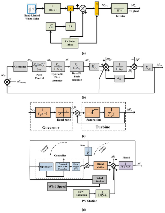
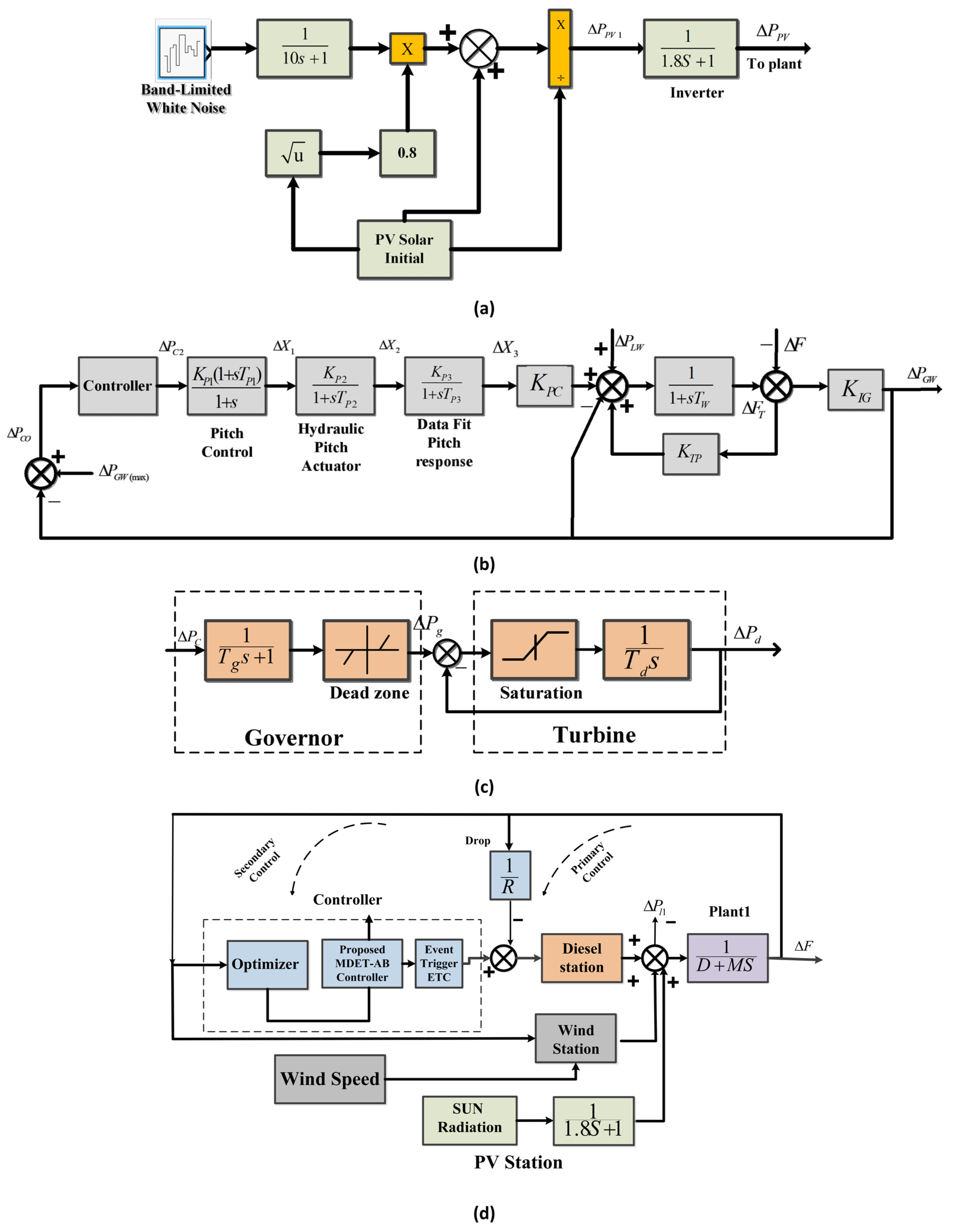
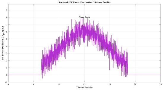
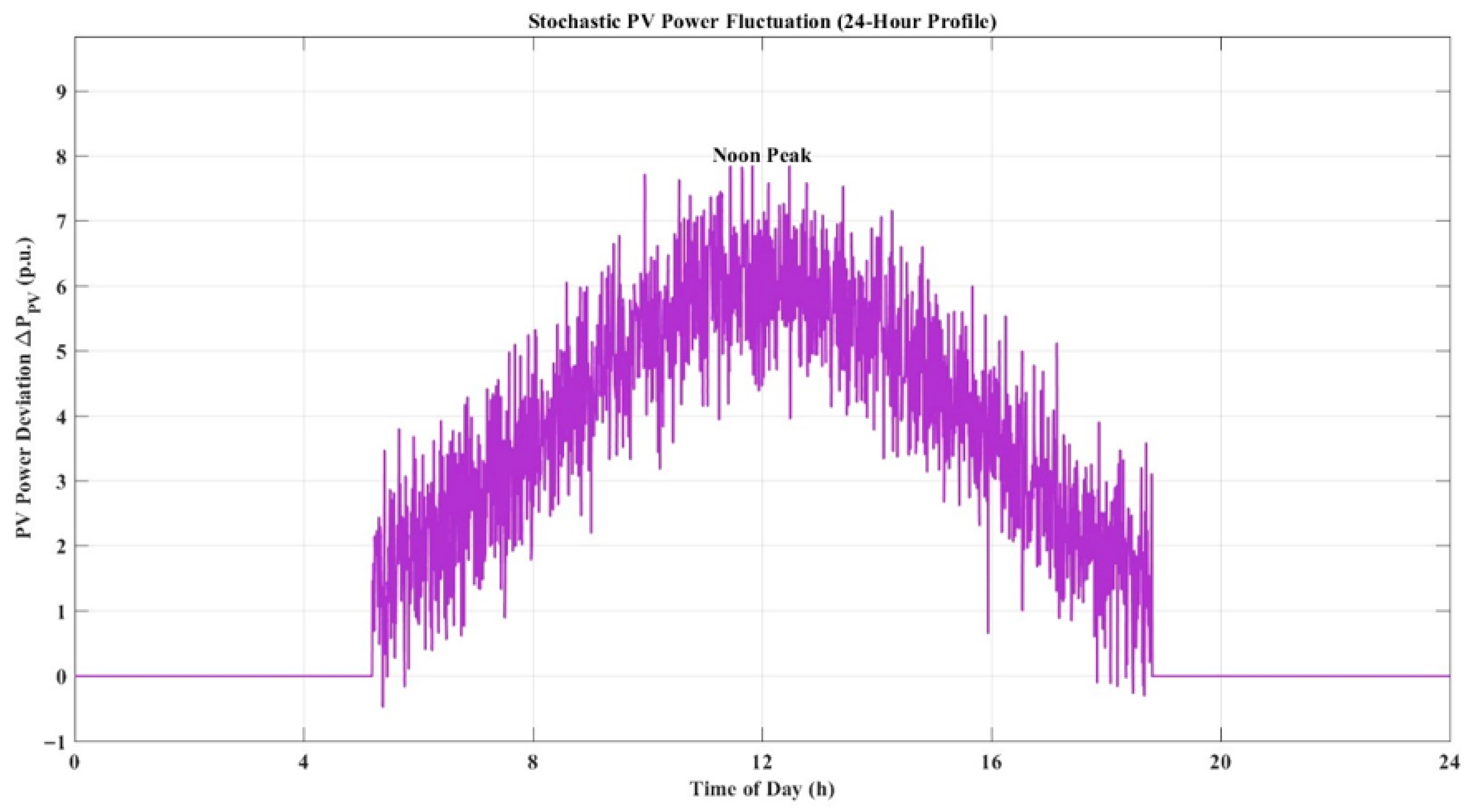
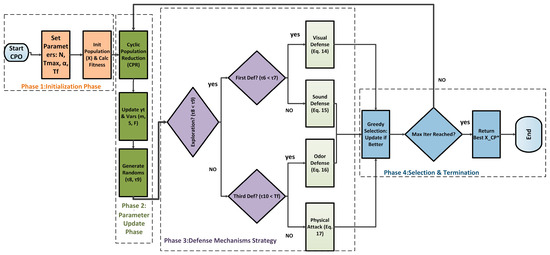
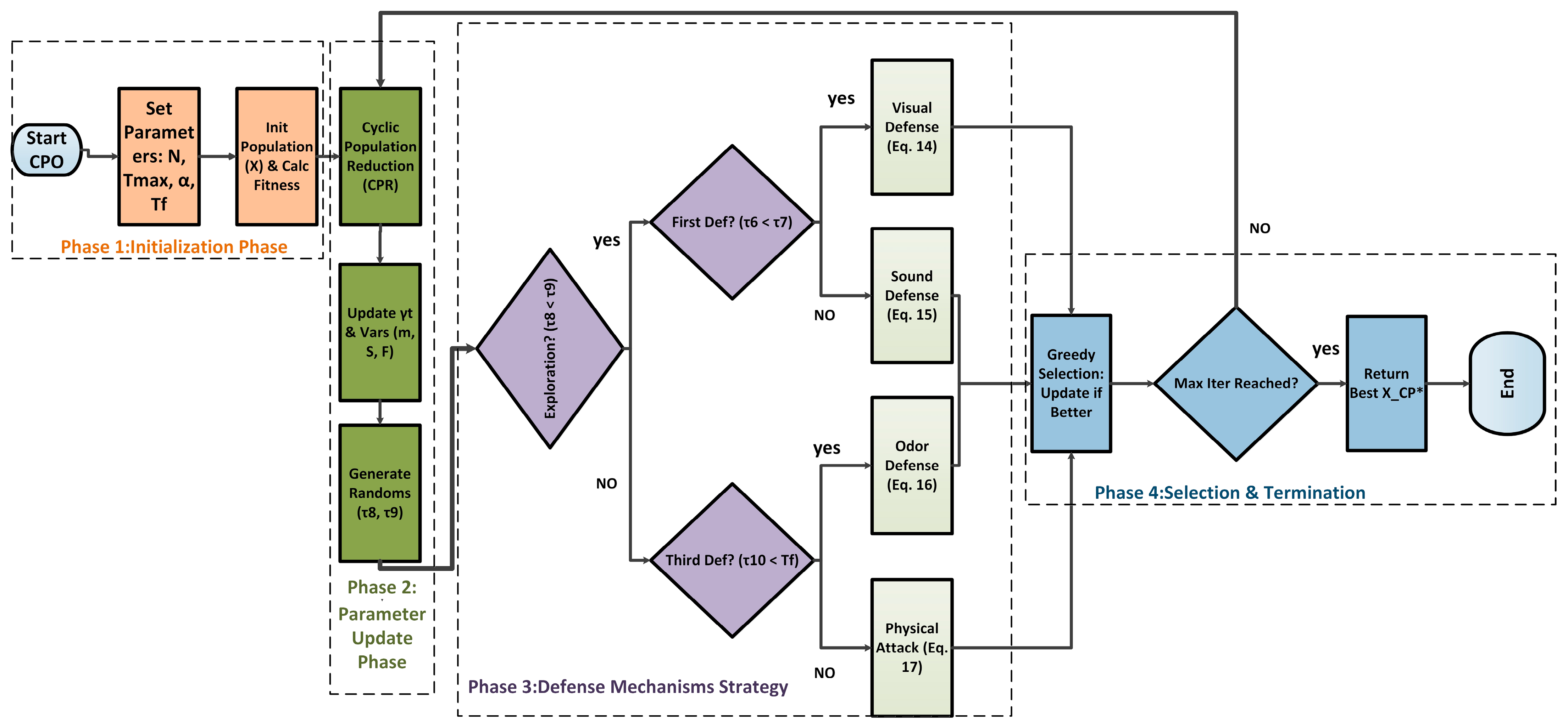
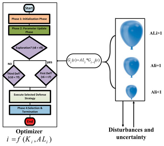
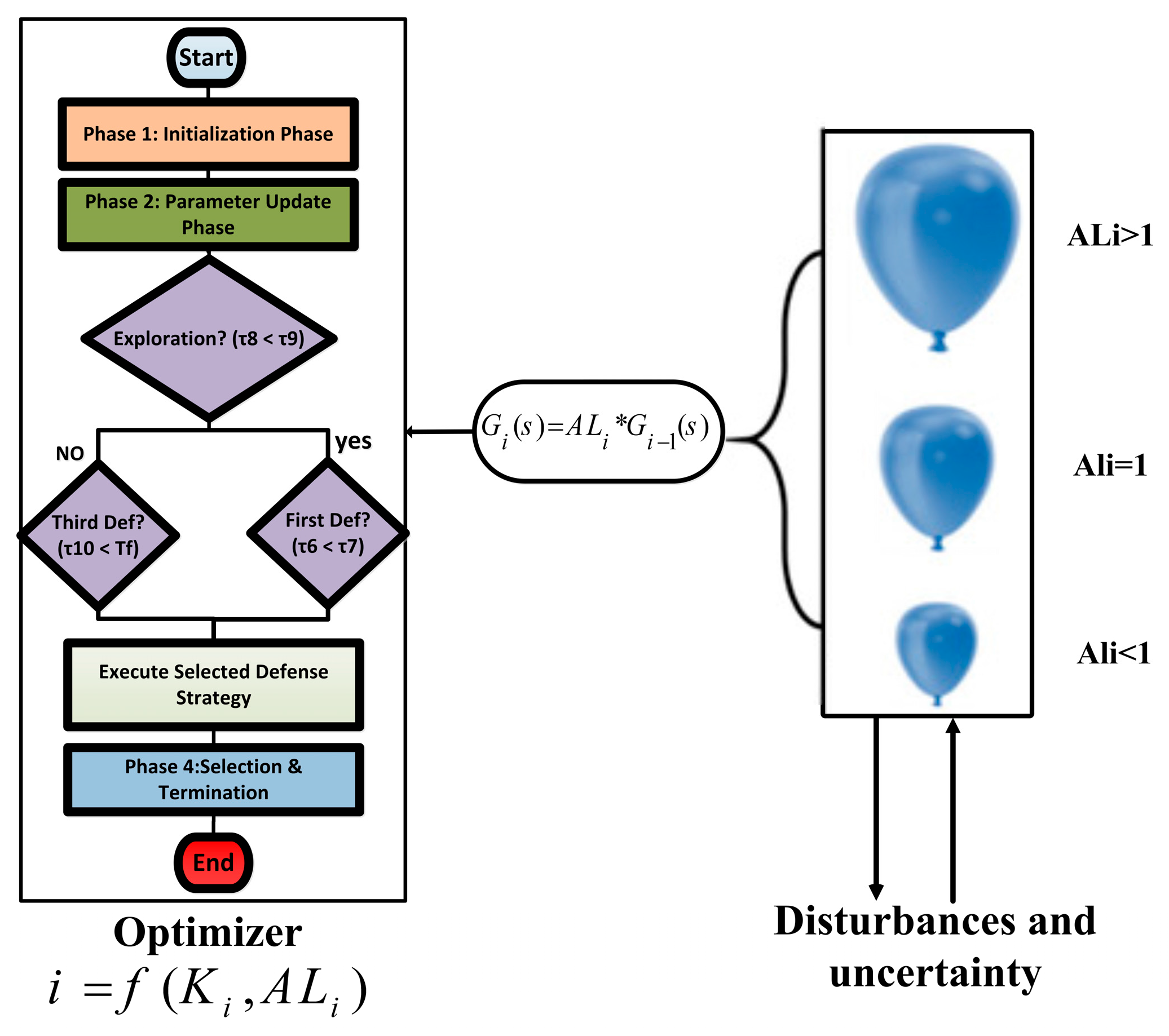
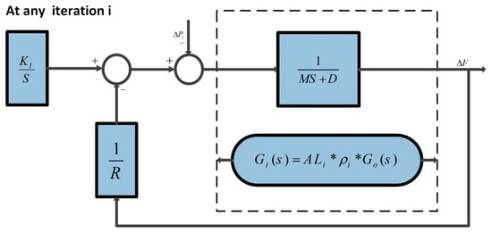
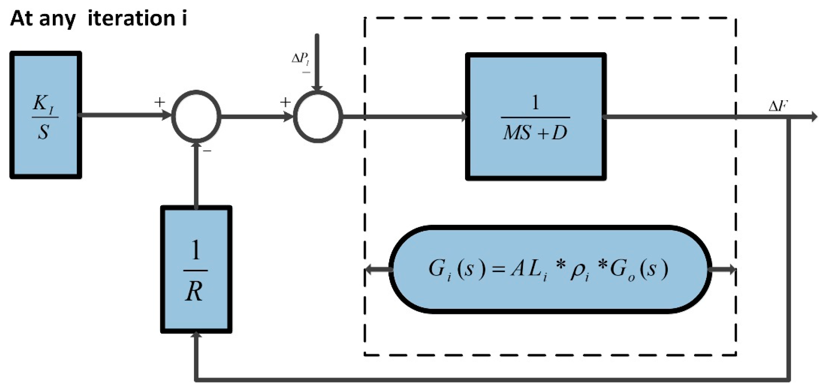
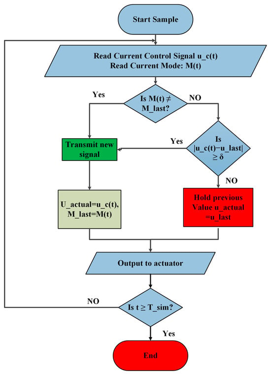
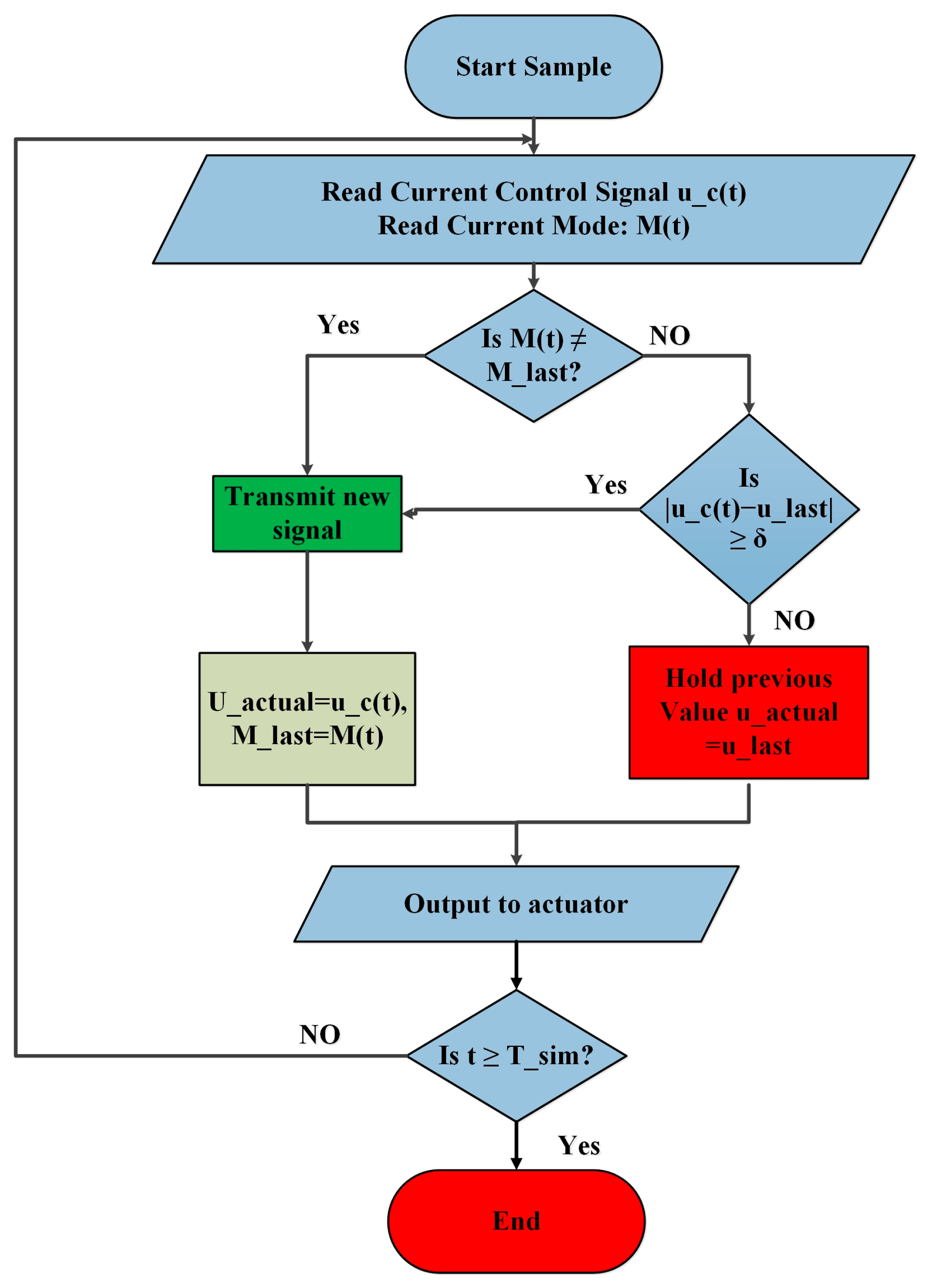
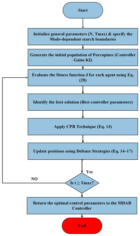
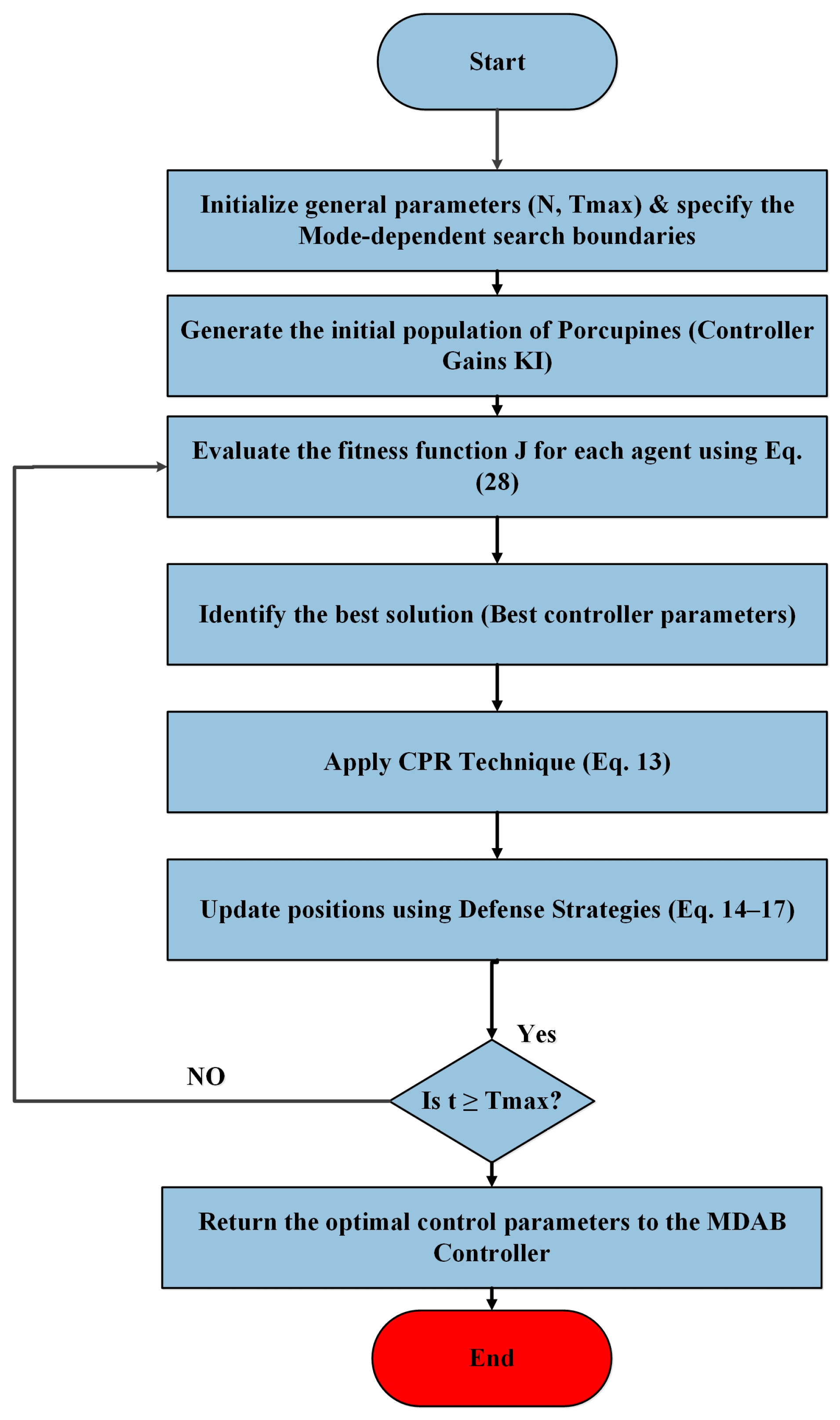
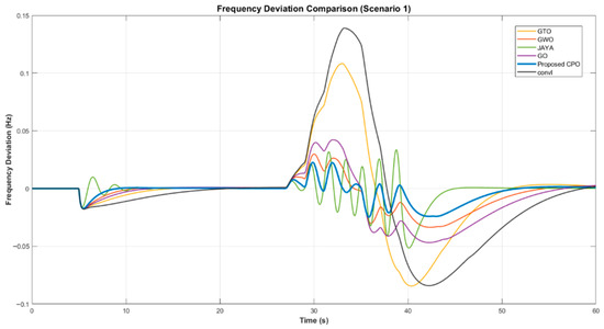
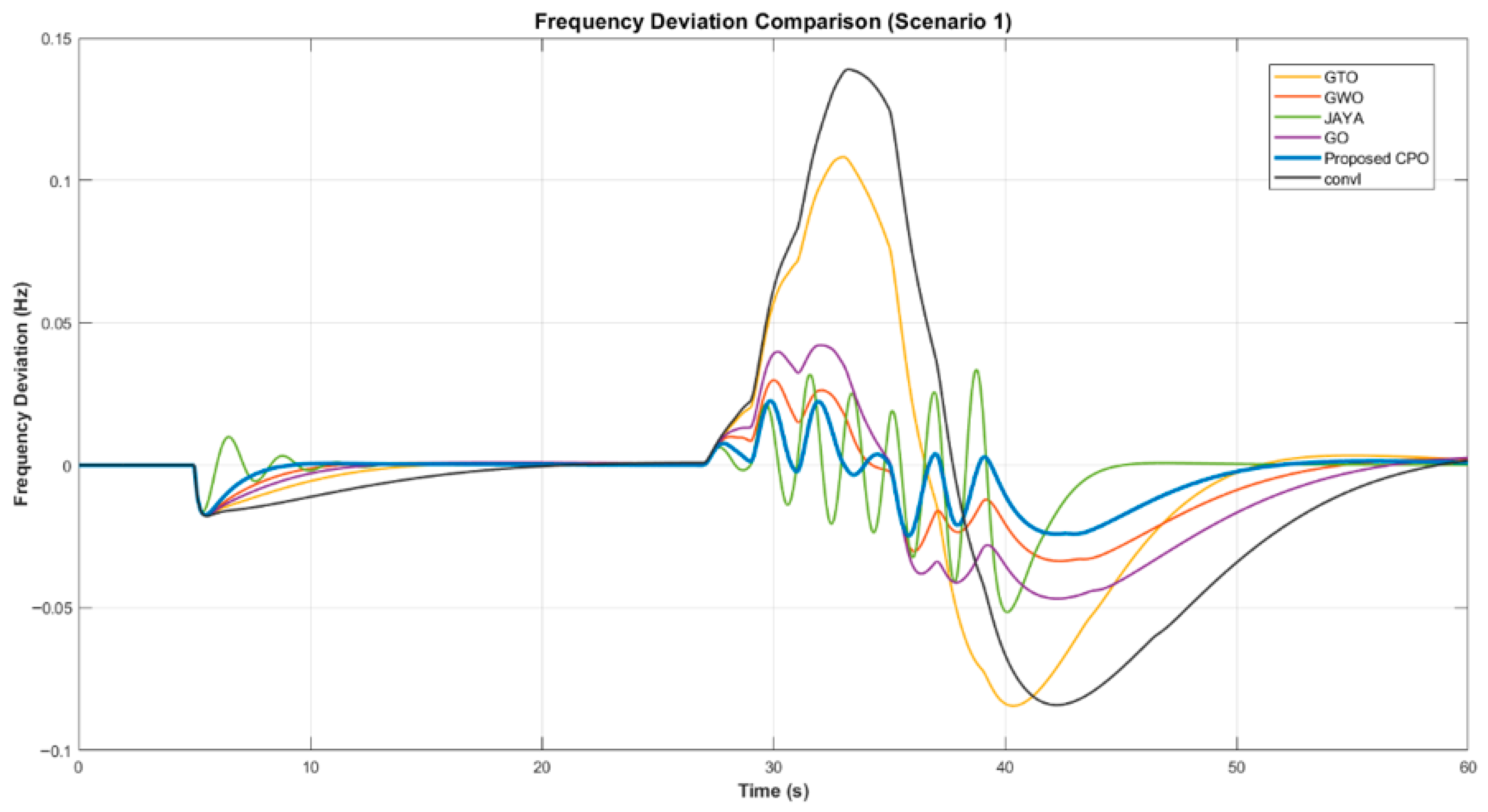
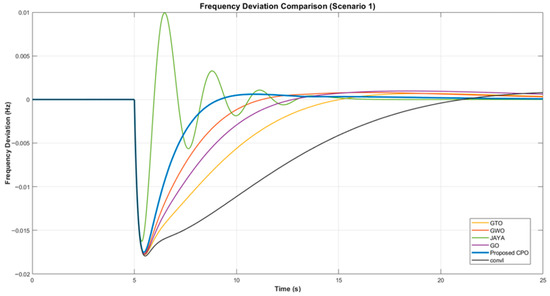
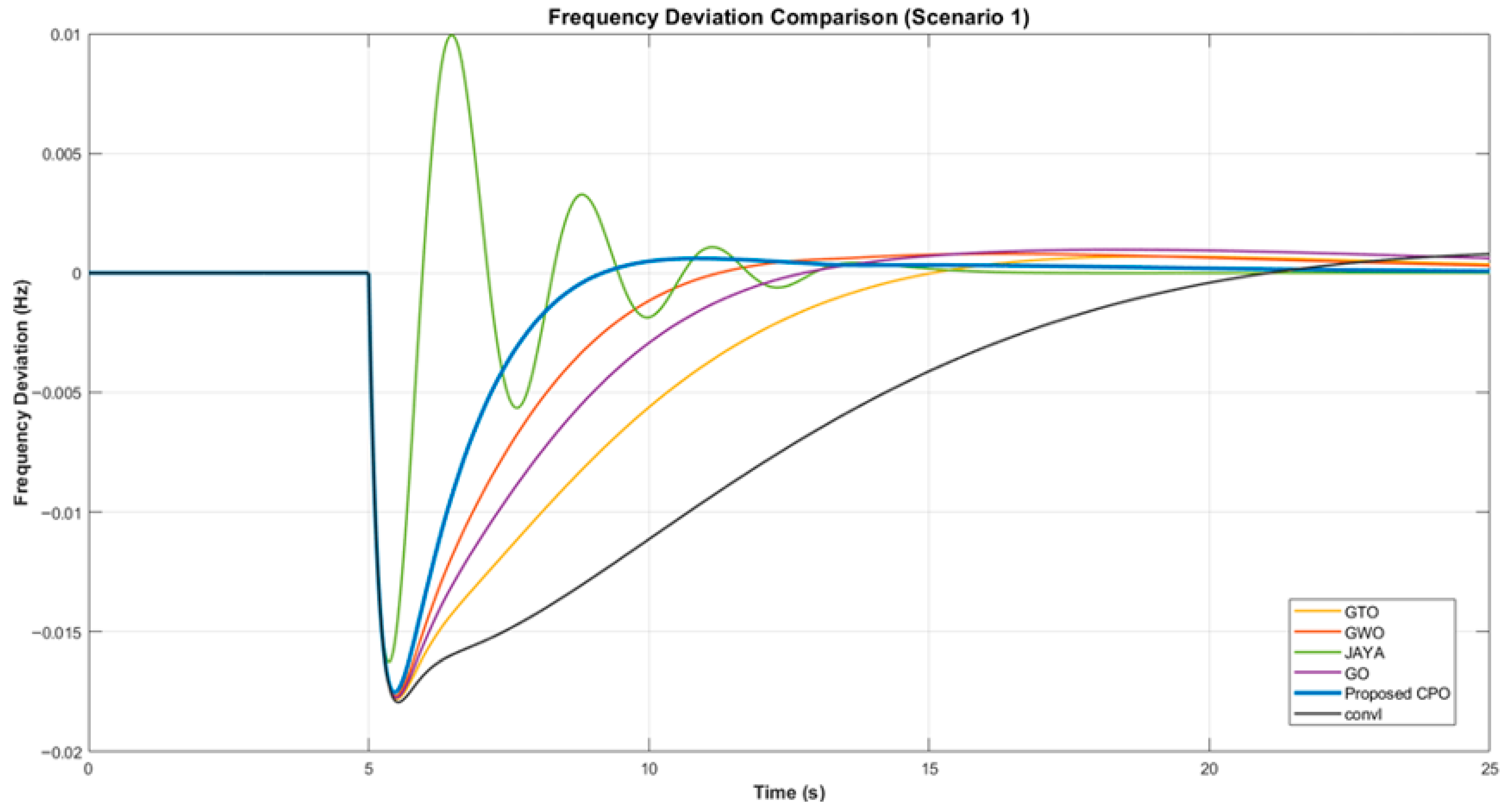
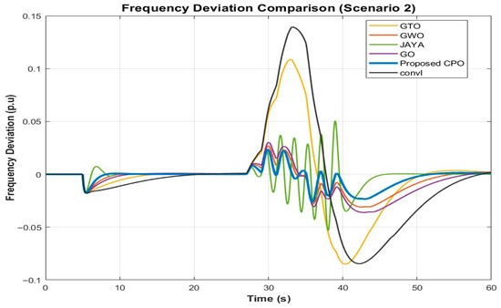
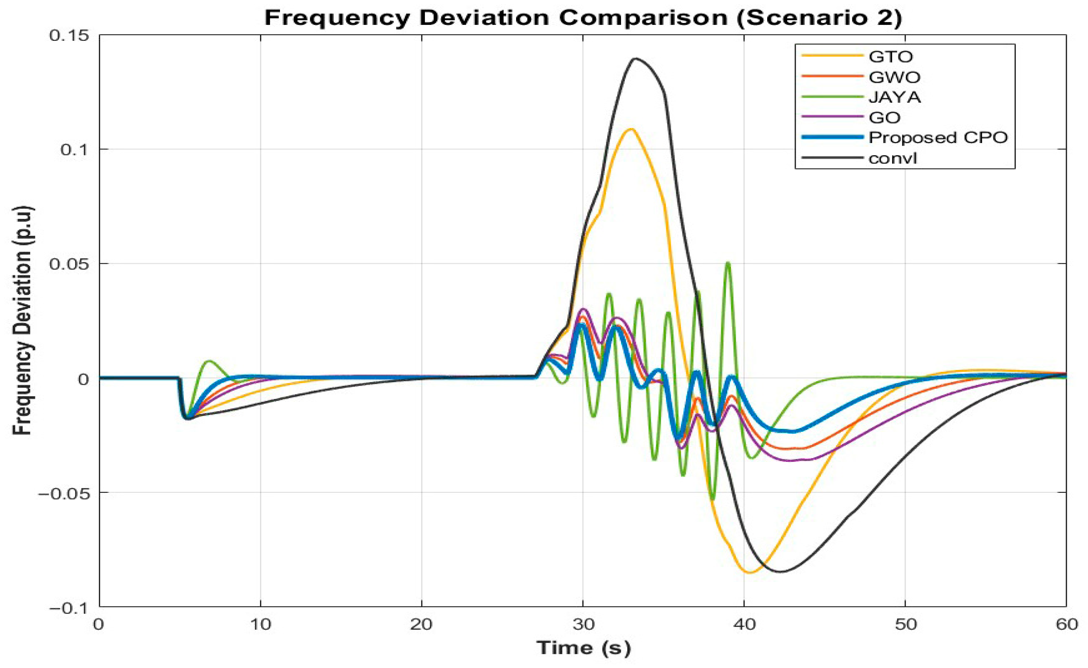
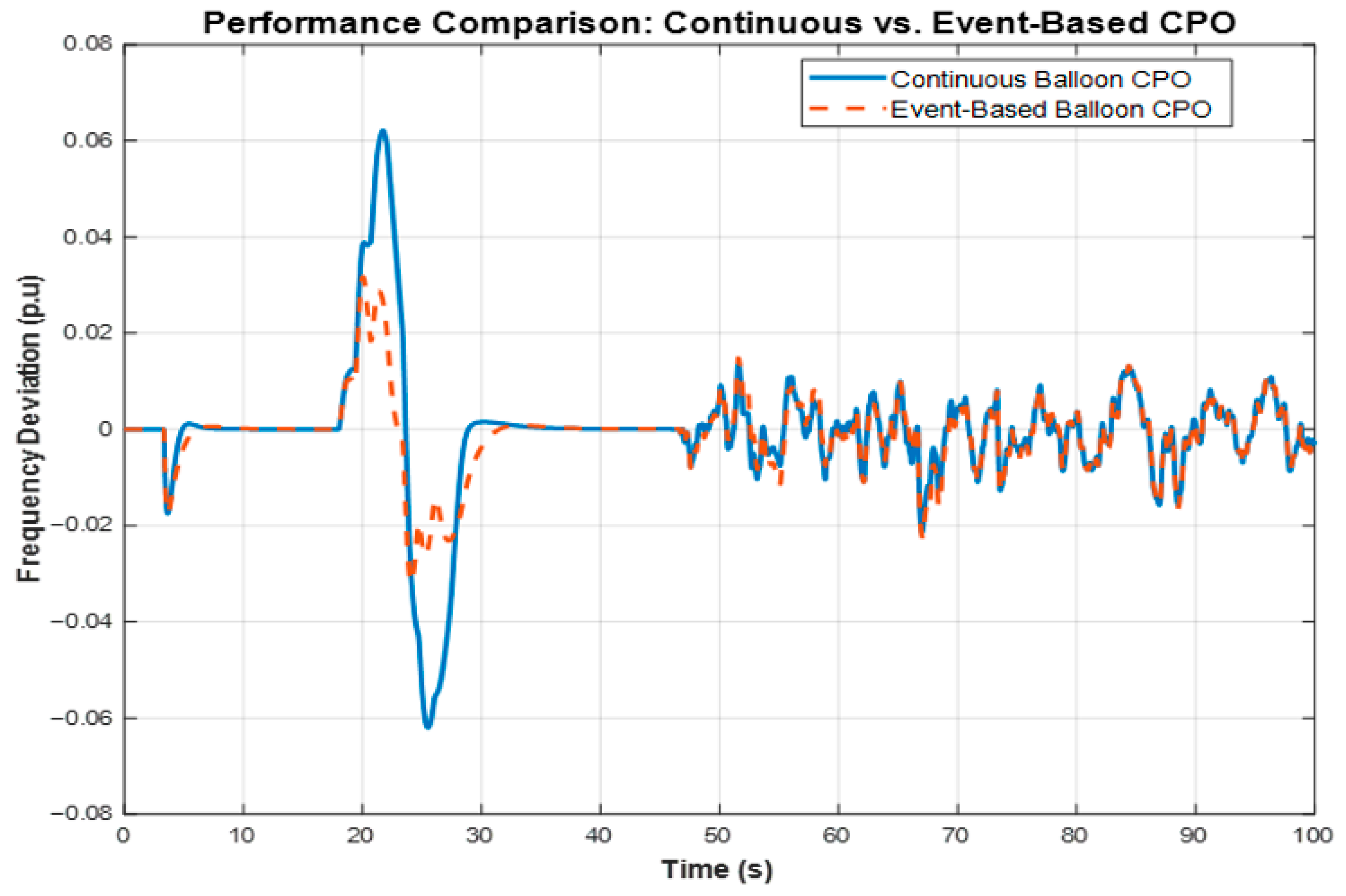
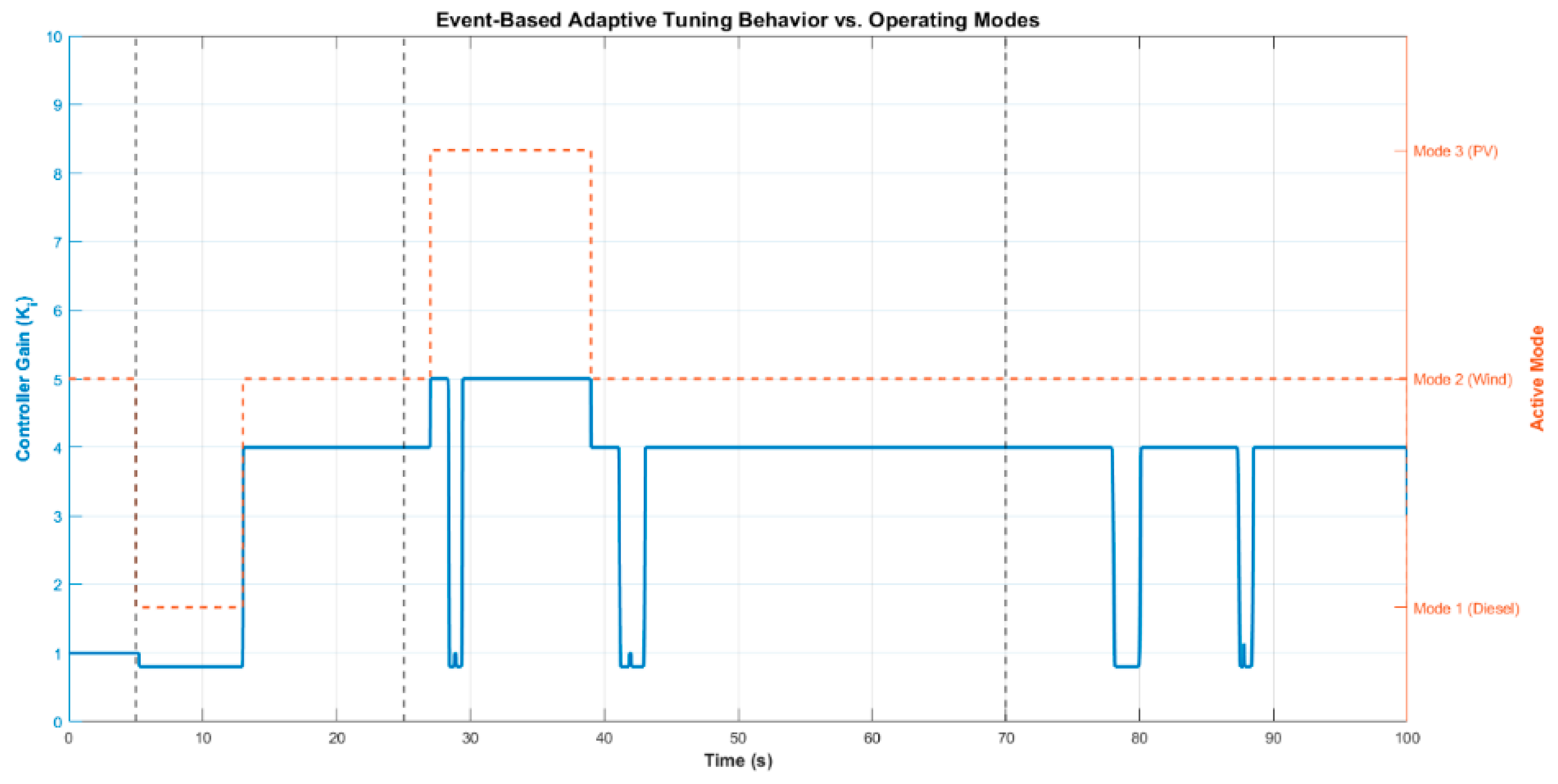
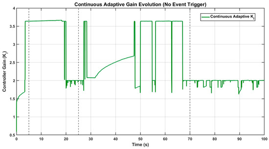
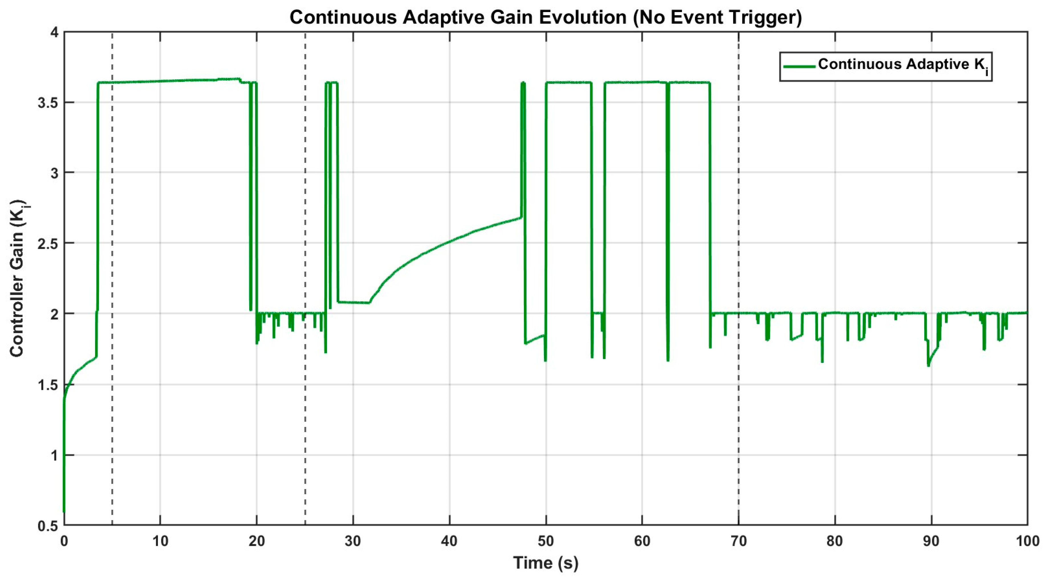
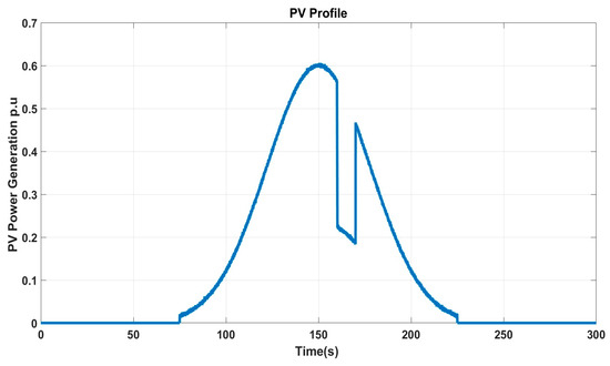
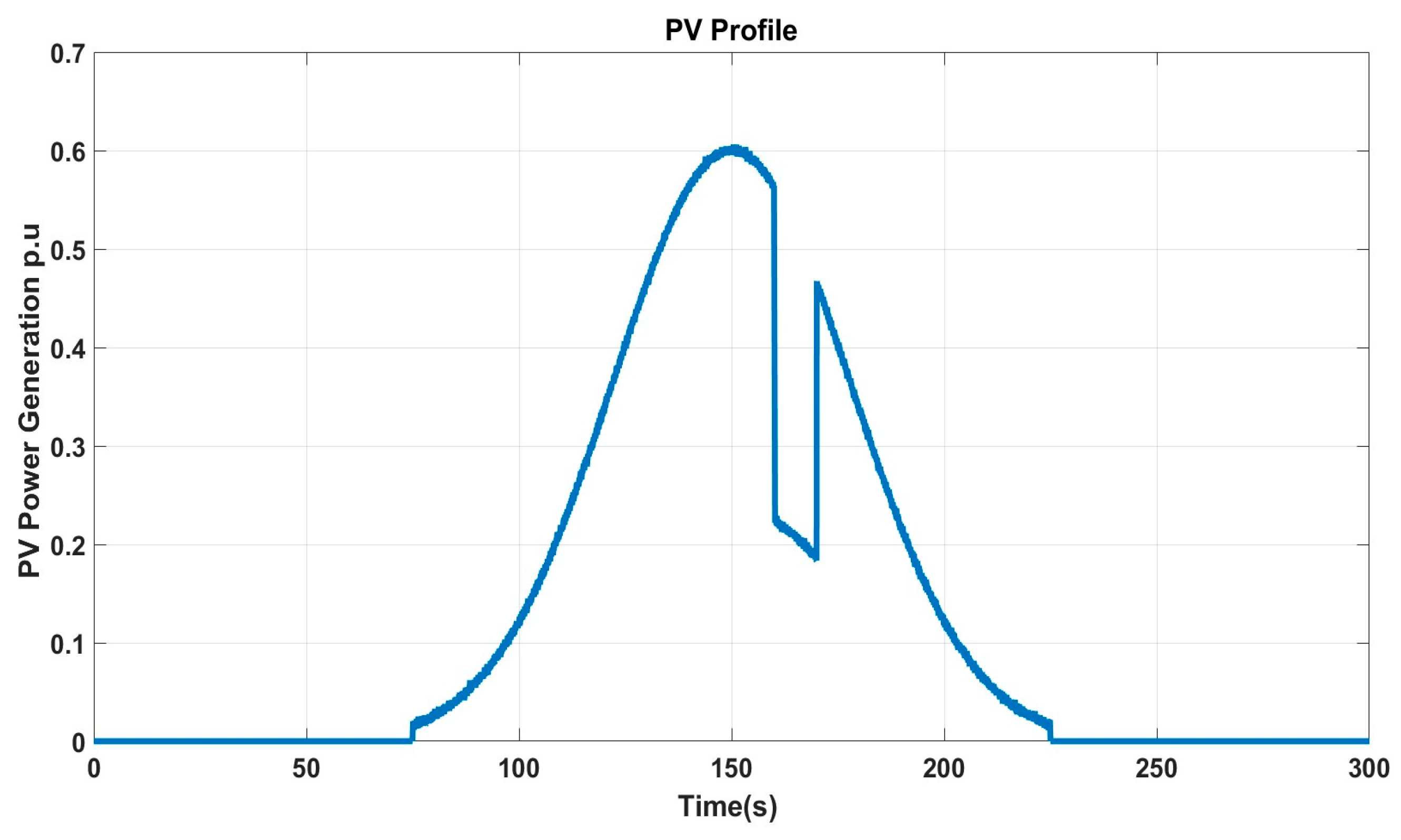
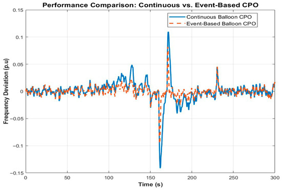
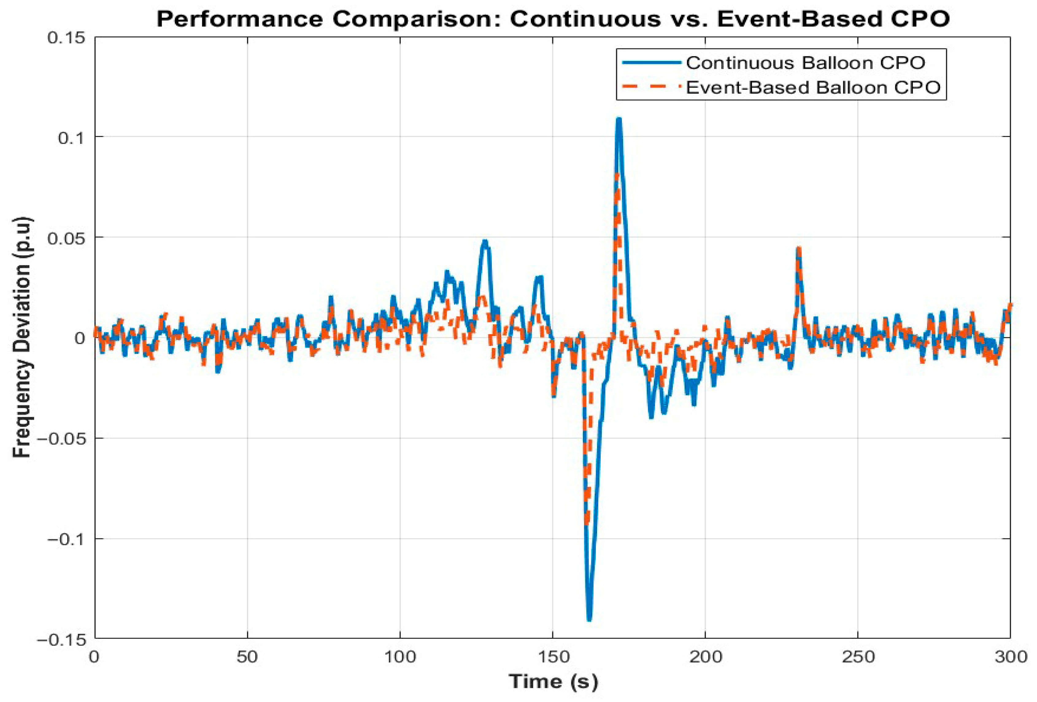
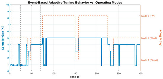
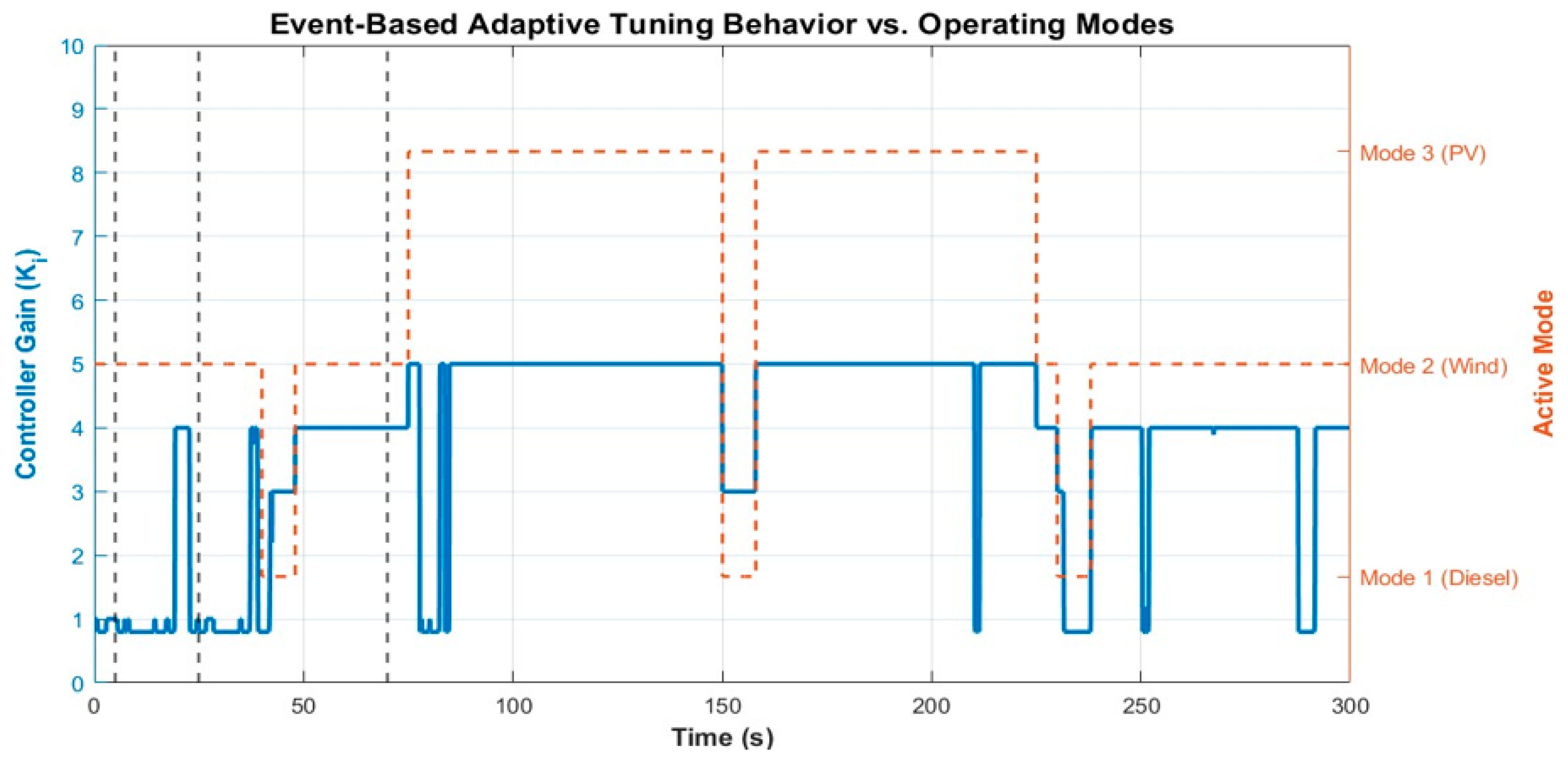
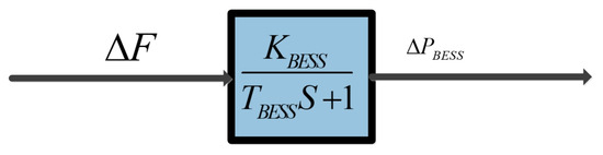
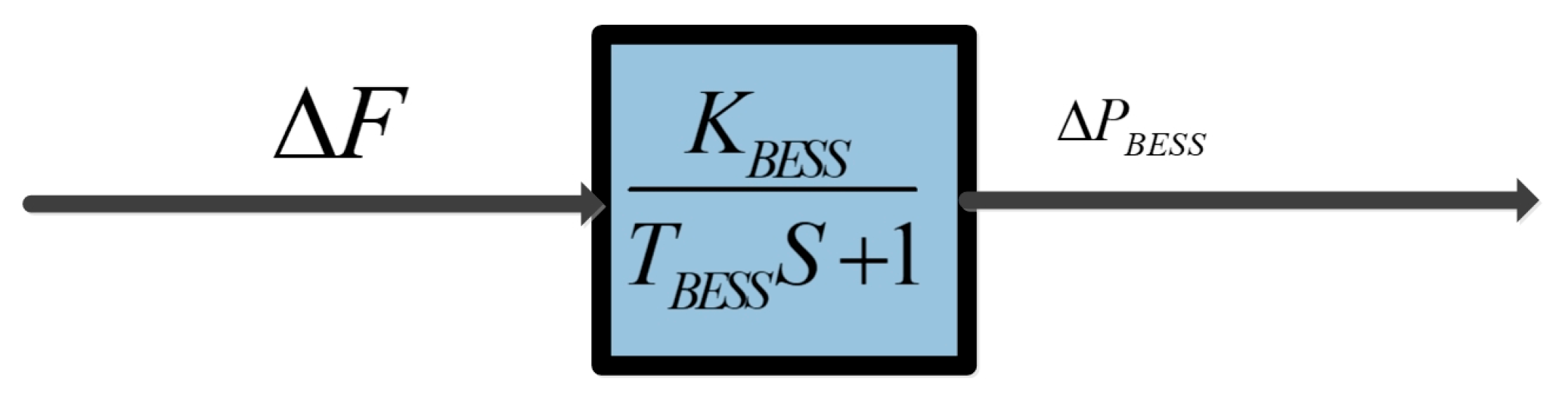
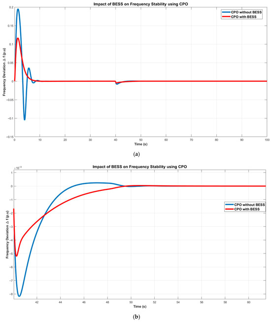
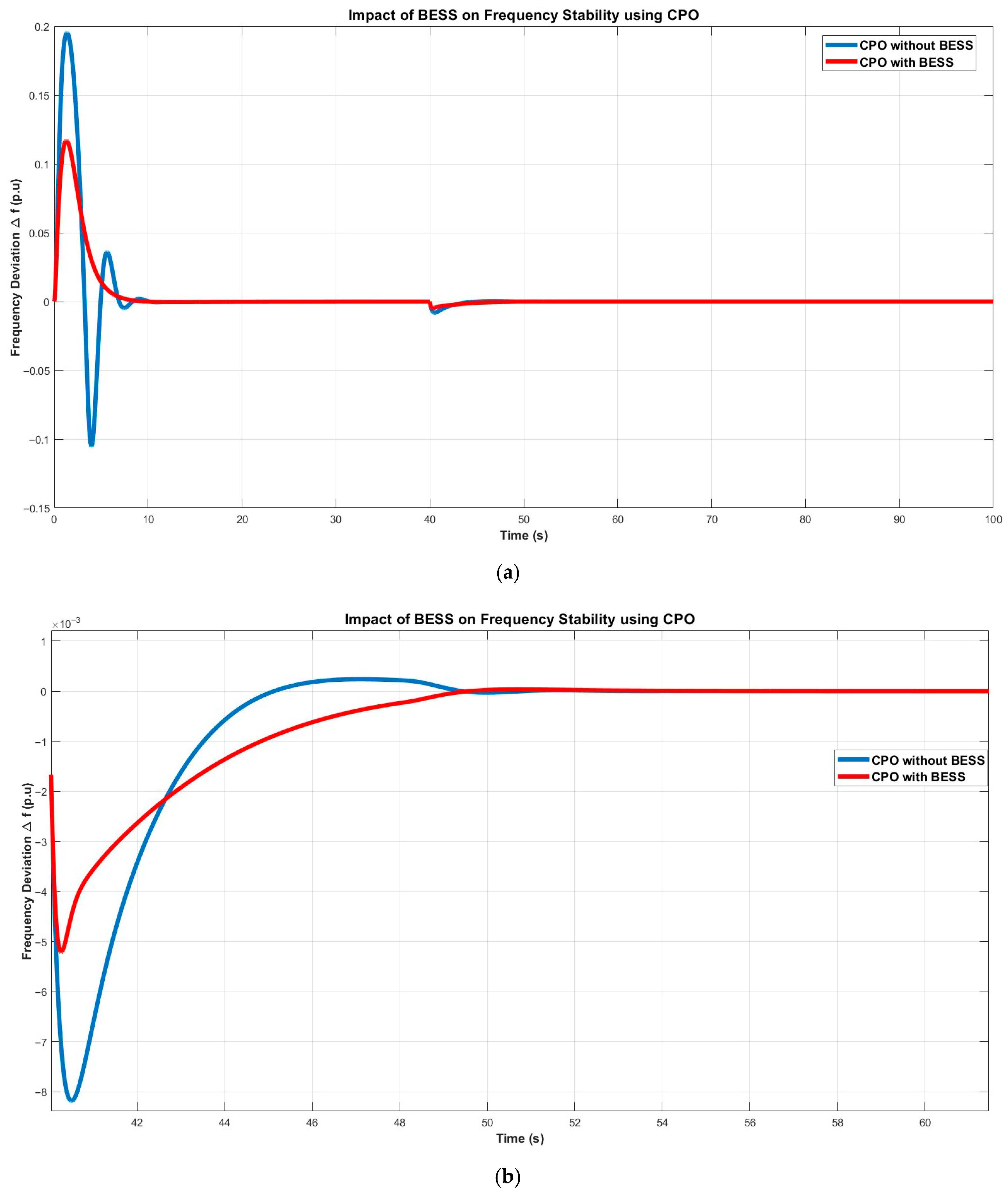
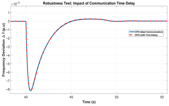
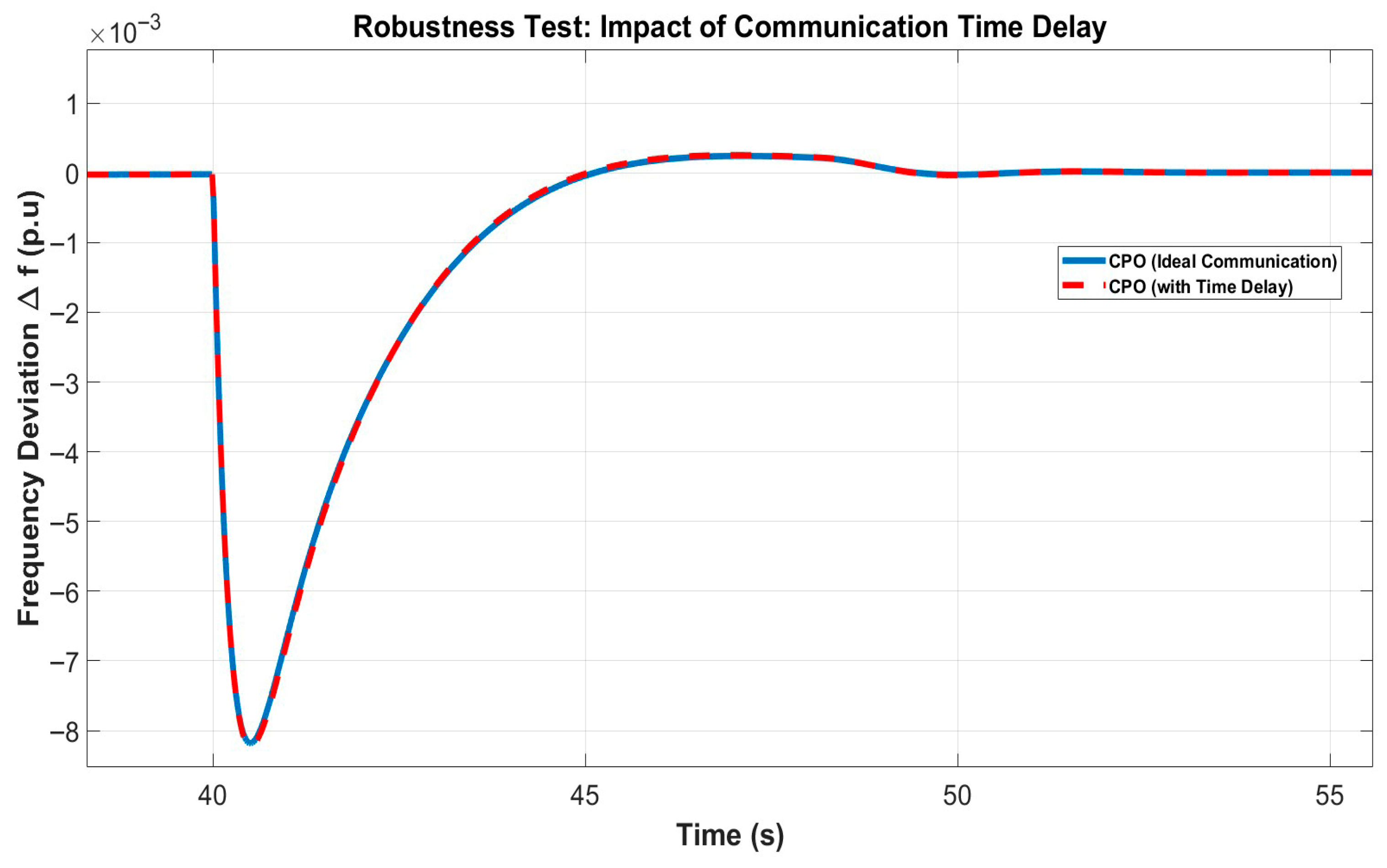
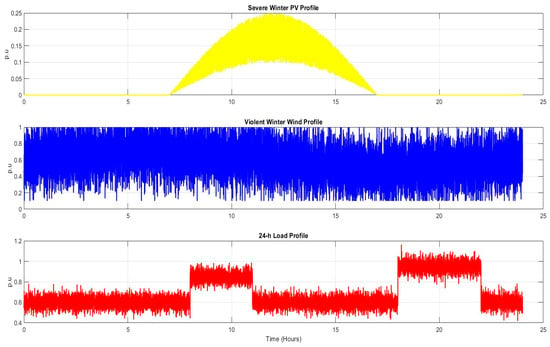
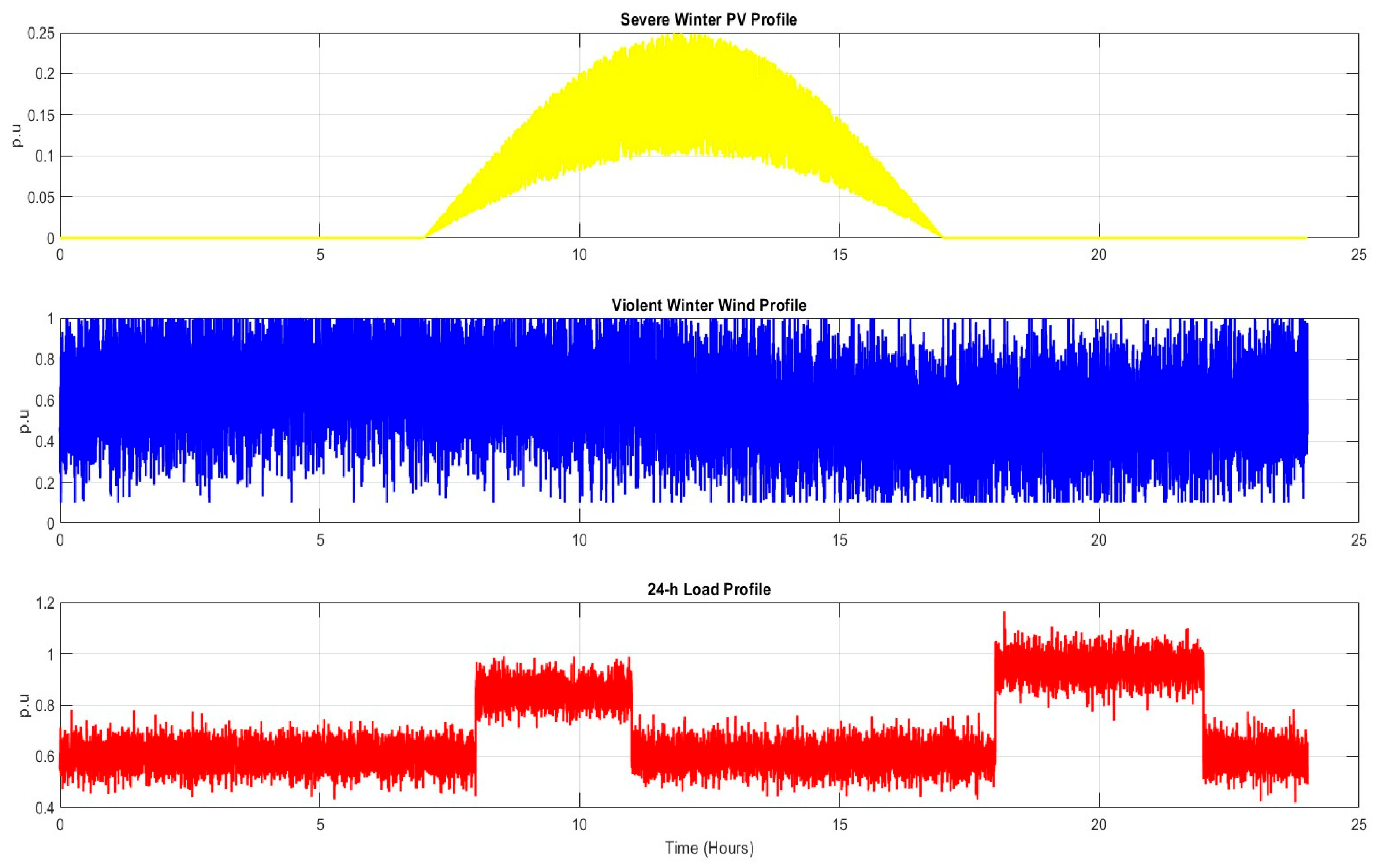
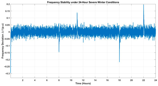
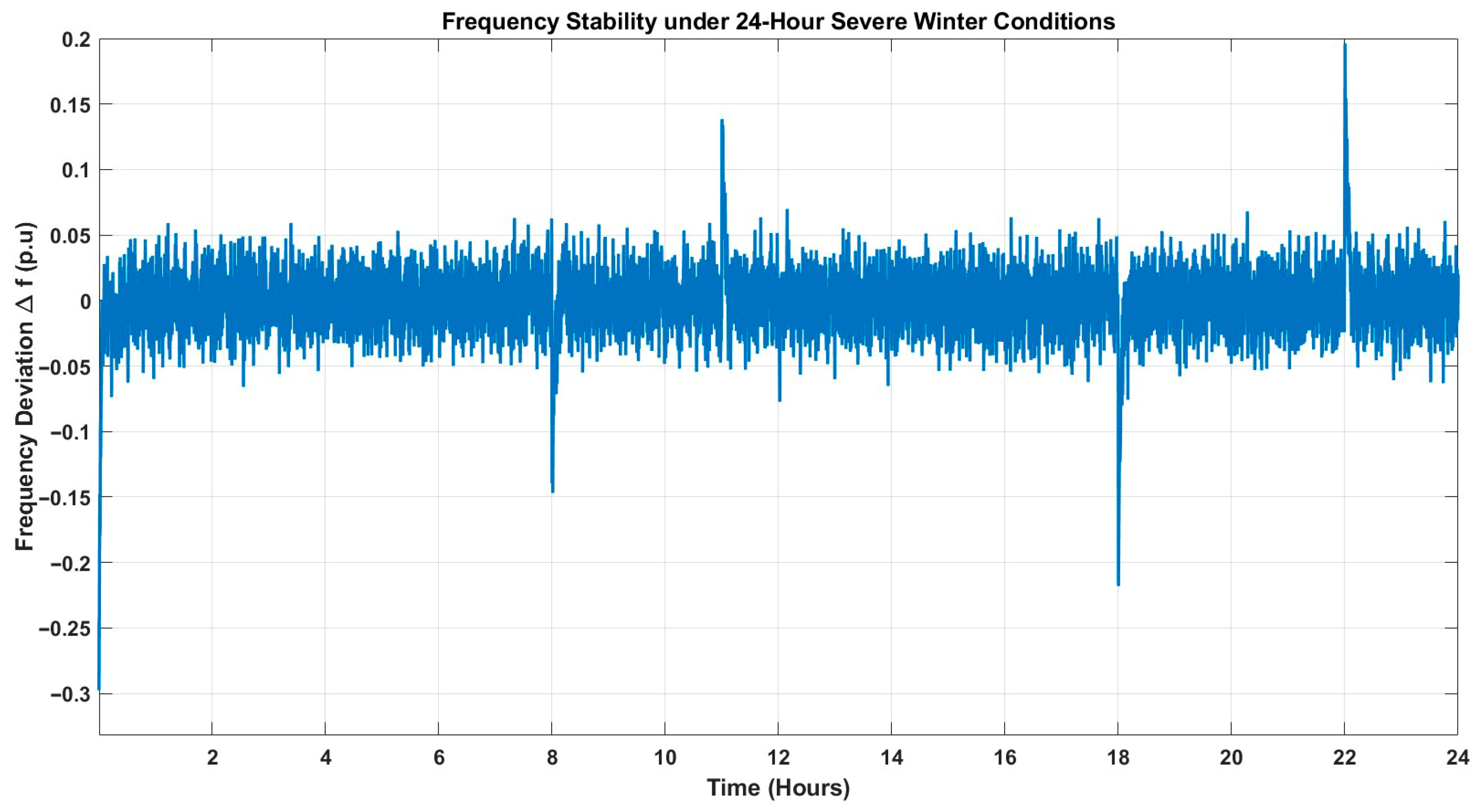

Disclaimer/Publisher’s Note: The statements, opinions and data contained in all publications are solely those of the individual author(s) and contributor(s) and not of MDPI and/or the editor(s). MDPI and/or the editor(s) disclaim responsibility for any injury to people or property resulting from any ideas, methods, instructions or products referred to in the content. |
© 2026 by the authors. Licensee MDPI, Basel, Switzerland. This article is an open access article distributed under the terms and conditions of the Creative Commons Attribution (CC BY) license.