


Abstract
Driven by the growing global energy demand and the pursuit of carbon utilization goals, dry reforming of methane (DRM) has attracted considerable attention for its ability to convert CO2 and CH4 into syngas. Biogas, an eco-friendly product of processes such as anaerobic digestion, is primarily composed of CO2 and CH4 and ideally meets the feedstock requirements for DRM. In practice, biogas is generated via anaerobic digestion of livestock manure and other organic waste, providing a stable and sustainable source for the DRM reaction and thus enabling waste valorization. Supported Ni0 catalysts have become a research focus in this field due to their high catalytic activity and moderate cost. Conventional particulate Ni0 catalysts, however, are prone to carbon coking in fixed-bed applications and are difficult to effectively recover and regenerate after the reaction; thus, they are often being discarded, leading to resource waste and environmental burden. To address these issues, this study has designed a novel metal-sintered fleece catalyst support and developed a corresponding reactor. The effects of the catalyst preparation method, activation conditions, and the support structure on DRM performance have been systematically investigated. The spent Ni-based catalyst could be regenerated via calcination to restore catalytic activity and enable multiple cycles of use, significantly extending the catalyst’s lifespan and offering both economic and environmental benefits. Experimental results have demonstrated that the reactor achieved a conversion rate exceeding 80% with near-complete product selectivity.
1. Introduction
1.1. Feedstock Sources
In the operating steel mills, mineral processing plants, and coal-fired power plants, carbon dioxide obtained through carbon capture and storage technology needs to be effectively utilized [1,2,3]. At the same time, the supply of “green methane”, such as methane from biomass [4,5] or from renewable feedstock sources [6,7]. has become increasingly important. The combination of captured carbon dioxide and green methane can produce syngas (CO + H2) through a process of dry reforming of methane (DRM), which is a key precursor for the synthesis of important oxygenated chemicals, such as methanol and dimethyl ether [8,9,10], or for fuel-alternative compounds by Fischer–Tropsch synthesis [11]. In addition, anaerobic digestion processes in the fields of sewage treatment, livestock and poultry manure, and landfills, among others, will produce a large amount of biogas, which is itself a mixed gas of carbon dioxide and methane. Although the specific composition of biogas varies with its different digested resources, it provides an off-the-shelf renewable pathway for the simultaneous provision of CO2 and CH4, thereby coupling waste treatment with the production of high-value-added chemicals and further promoting the development of a circular carbon economy.
1.2. Dry Reforming of Methane (DRM)
DRM, as an environmentally friendly catalytic process, can convert two major greenhouse gases, CH4 and CO2, into syngas, a mixture of H2 and CO, which is an attractive and valuable gaseous feedstock for subsequent organic synthesis reactions [12,13,14]. It can synthesize oxygenated hydrocarbons, such as methanol, ethylene glycol, and dimethyl ether, as well as fuel-range hydrocarbons by the Fischer–Tropsch synthesis. DRM is a strongly endothermic reaction, so the highest conversion value can be achieved at high temperatures [15,16,17]. The endothermic and catalytic reaction is shown in Equation (1).
is the reaction enthalpy at 298 K.
Despite its environmental advantages, the catalysts used in DRM tend to deactivate due to coke formation caused by three side-reactions. Firstly, it is caused by methane decomposition, as shown in Equation (2), which occurs at a high temperature. Secondly, the CO disproportionation reaction is based on the exothermic Duja Equation (3), which occurs at lower temperatures only. Finally, the reverse water–gas shift Equation (4) proceeds simultaneously at moderate temperatures, resulting in a syngas ratio lower than the theoretical unity.
1.3. Objectives
The present research investigates the catalytic DRM concept and introduces a novel catalyst carrier. The objectives are fivefold:
- It examines the coating of Ni0-catalysts on a metal fleece candle to counteract fixed DRM problems;
- It assesses the reaction yields and efficiencies in long duration experiments;
- It demonstrates the quality of the produced syngas;
- It assesses the operational stability of the catalyst/fleece system and its easy regeneration (if coking occurs);
- It describes the possiblescalability and energy consumption.
2. Materials and Methods
2.1. The Sintered Metal Fleece Reactor
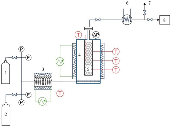
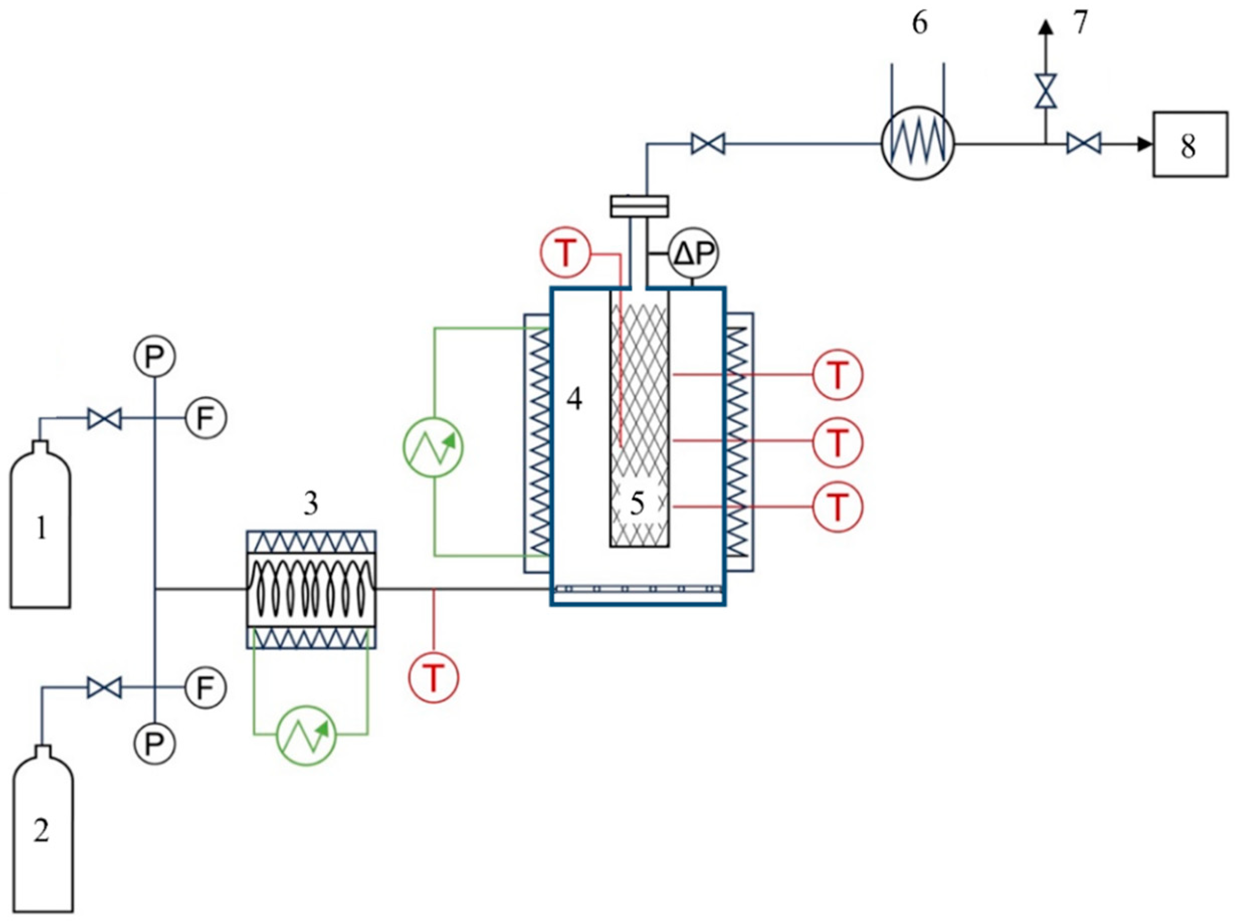
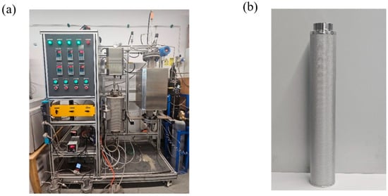
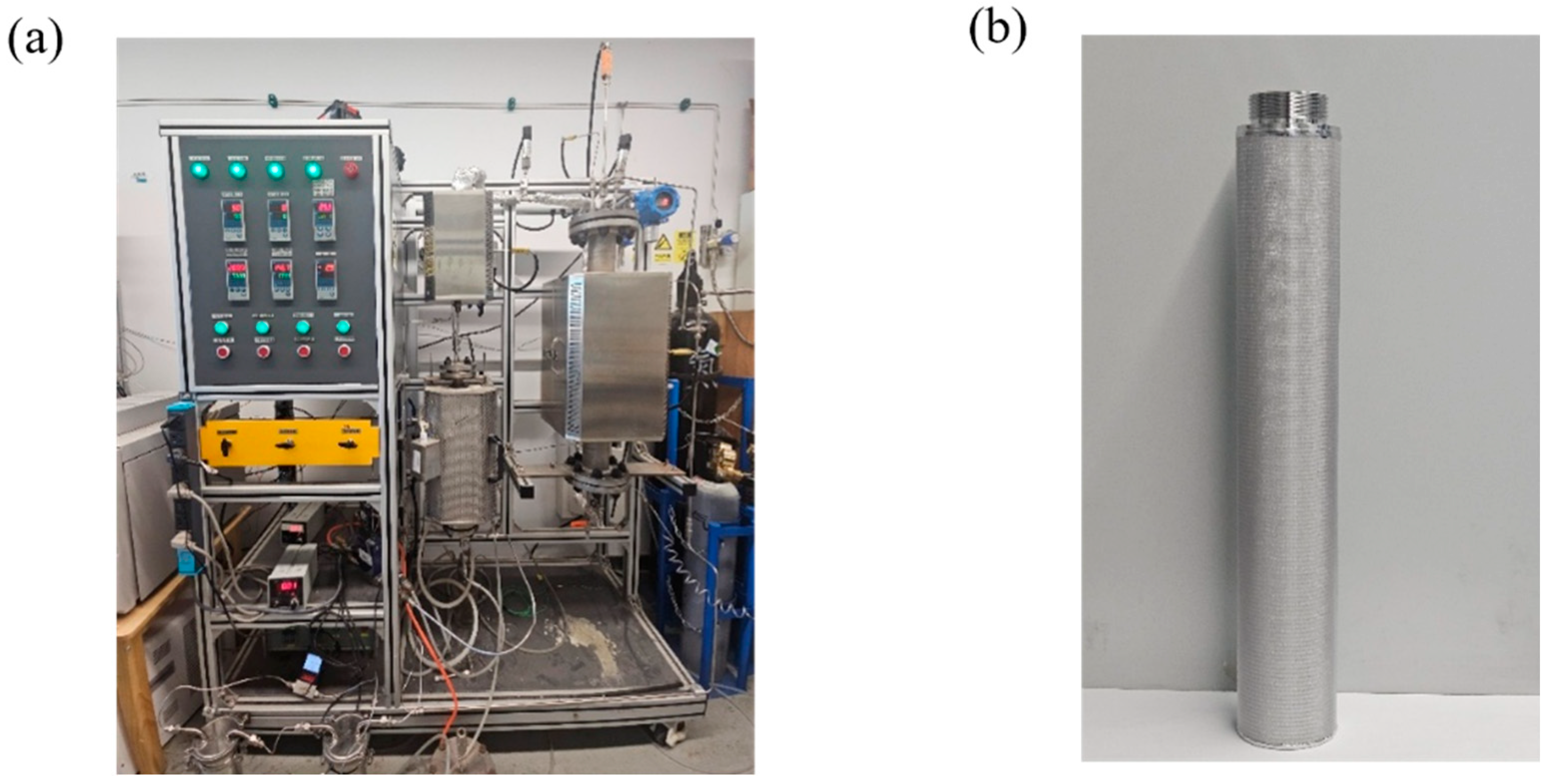
The stainless-steel sintered fleece candles were supplied by Boyue Filtration Equipment Co., Ltd., Henan, China. Details of the candles’ geometry are given in Supplementary Materials Figure S1. The Ni0-loaded fleece candle was centrally mounted in the reactor housing (Shanxi, China), and the required auxiliaries (gas feed (Beijing, China), T and P probes (Shanghai, China), electrical heating (Shanxi, China) and analytical equipment (Beijing, China)) were installed. Figure 1 illustrates the experimental layout. Figure 2 shows the physical diagrams of the experimental setup and the sintered fleece.
Figure 1.
Layout of the experimental DRM fleece reactor. (1) CH4 and CO2 cylinders (Beijing, China) with relief valve for pressure, P, and mass flow meter, F; (2) N2 cylinder (Beijing, China) with identical fittings; (3) Feed gas preheater (Shanxi, China); (4) temperature T controlled reactor (Shanxi, China) with (5) sintered metal fleece candle; (6) cooler (Shanxi, China); (7) vent (Beijing, China); and (8) GC (Beijing, China).
Figure 2.
Photographically illustrates of (a) the overall setup; and (b) the fleece candle.
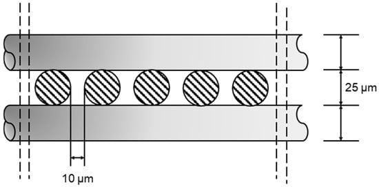
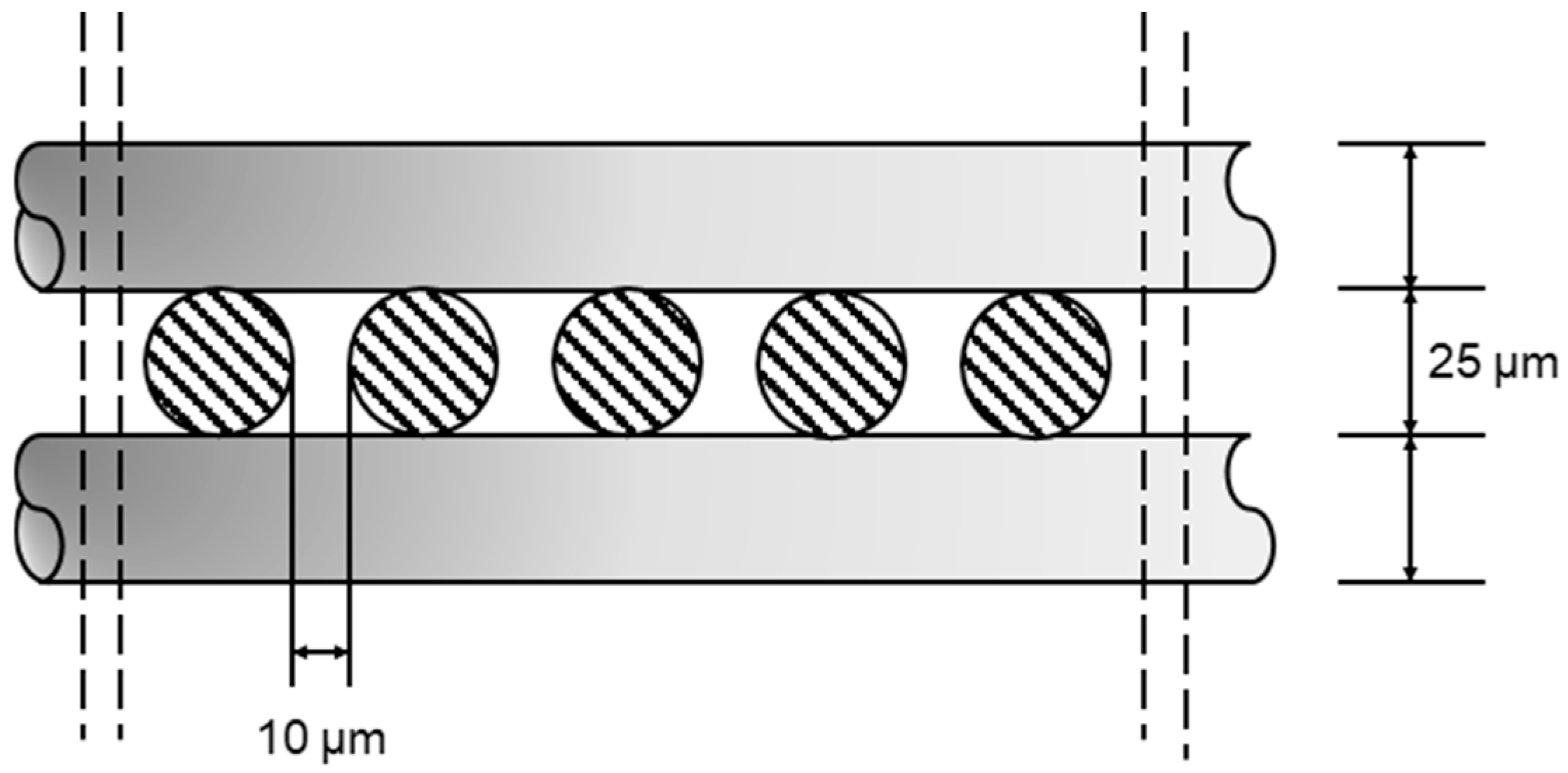
The fleece was fabricated from AISI 304 sintered stainless-steel mesh, with a candle of 50 mm outer diameter and 295 mm active length, fixed within a concentric housing of 76 mm inner diameter. The feed gas can be distributed uniformly to the outer tube and penetrate through the fleece pores. Table 1 lists the relevant properties of the selected fleece. The 1.7 mm thick metal fleece comprised several fiber layers stacked in a cell geometry, as illustrated in Figure 3. The metal fibers had a density of 8320 kg/m3. Other physical properties are outlined in Table 1.
Table 1.
Fleece characteristics.
Figure 3.
Cell geometry of the fleece.
The wash-coat thickness on the fleece fibers is calculated from the catalyst weight, the specific surface area of the fleece, and the loaded weight and density of Ni.
At set flow rates of N2 (inert carrier), CH4 and CO2 are mixed during electrical preheating, and the reaction temperature is set and regulated by K-type thermocouple (Shanghai, China) monitoring. All safety measures were taken to avoid gas leakage, and leak testing was performed by a pressure-hold measurement. Several thermocouples were fixed within and onto the fleece reactor. The flow rate of CH4 and CO2 was 25 mL/min each, although lower rates were also tested for the kinetic study. N2 was only used as a gas at the start-up and stop procedures. The temperature setpoints were 650, 700, and 750 °C. The DRM was started once a stable reaction temperature was achieved. Samples were collected at regular intervals and analyzed according to the tools and methods in Supplementary Materials Table S1. The catalyst was reduced to Ni0 before the DRM reaction by H2 for 3 h at 25 mL/min and 700 °C. The CH4 and CO2 conversions can be defined by their respective inlet (feed) and outlet concentrations:
and the H2 and CO yields can be given by:
2.2. Coating of the Fleece Reactor with Catalyst
In previous investigations, wet-spray impregnation or sol–gel deposition of the metal catalyst active species onto inert supports of Al2O3, SiO2, MgO, and others were mainly applied in the fixed-bed reactor. The results using Ni/ZSM-5 [18], Ni-Al2O3 [19,20], and other Ni-based catalysts [21,22,23], as well as the addition of Cerium [24,25,26] and other support-Ni combinations [27,28,29,30,31], were reported. The conversion of CH4 and CO2 ranged from 12 to 94% and 30 to 93%, respectively. With over 125 publications since 2017, the literature has been important, but not all process data have been supplied. Despite being an important operational parameter, the possible catalyst deactivation due to carbon deposit has rarely been reported with quantitative data. Ni has been the preferred active species, while MgO or CaO have been widely used as fixed-bed supports—although the use of CNT-support has been promoted since 2023. The tested temperatures have varied from 600 to 900 °C. The applied CH4/CO2 molar ratio was mostly 1/1. The present research has relied on the sole spray impregnation of the fleece by the Ni active species precursor.
The fleece was first immersed in 0.5 mol/L HCl (Beijing, China) solution for acid etching for 24 h. The fleece was subsequently rinsed with deionized water at a neutral pH. The saturated nickel nitrate solution was prepared by adding Ni(NO3)2 (Shanghai, China) to ultra-pure water with 18.75 g/L of nonionic detergent, AEO-3 (Shanghai, China) or AEO-9 (Shanghai, China). AEO-3 and AEO-9 are both RO(CH2CH2O)nH, R=C12–16 alkyl, where AEO-3 n = 3 and AEO-9 n = 9. The molecular weight is about 315 Da for AEO-3, and about 590 Da for AEO-9. Using a pressurized spray, the saturated solution was evenly deposited onto the fleece at a set weight. After drying (Shanghai, China) at 80 °C, the coated fleece was calcined (Tianjin, China) at 700 °C for 3 h in air. H2 was used for reduction at 700 °C for 3 h. The catalyst and fleece were then ready for testing.
2.3. Catalyst Characterization Methods
2.3.1. SEM
The surface morphology of the Ni/fleece catalyst sample was observed using scanning electron microscopy (SEM) (Shenzhen, China). The sample was directly adhered to conductive tape (Beijing, China) and sputter-coated with gold for 45 s prior to imaging.
2.3.2. XRD
X-ray diffraction (XRD) was determined by a Rigaku Miniflex instrument (Tokyo, Japan) at 40 kV and 40 mA. The data were recorded at every 0.02° at a 2θ angle ranging between 5 and 85, which were assessed toward the phases of the fresh catalysts. The Scherrer formula in Equation (9) was applied for calculating the mean crystallite size of the catalyst:
with λ is the radiation wavelength (0.15406 nm), while θ and β are the Bragg diffraction angle (in radians) and the line broadening at half-maximum intensity, respectively.
2.3.3. BET
The specific surface area of the Ni/fleece catalyst was measured by a specific surface area porosity adsorber (Shanghai, China). Before the test, the sample was vacuum degassed at 300 °C for 8 h.
2.4. The Reaction Rate Equation in the Fleece Reactor
With respect to kinetic rate expressions for the DRM reaction, the literature is limited, although it has accepted that CH4 dissociation can be a rate-determining step (RDS) [32]. Zhang and Verykios [33] came to that conclusion by applying the Langmuir–Hinshelwood model to a Ni catalyst. The CH4 RDS approach was confirmed by Nandini et al. [34] at moderate temperatures, while the RDS shifted to the reaction of CO2 and CH4 at high temperatures. Full details about the Langmuir, Hinschelwood, Hougen, and Watson (LHHW) model approach, including its advantages and shortcomings, are given in Hayes and Kolaczkowski [35]. Other studies also confirmed the CH4-driven reaction model, as determined from experiments with a Ni/SiO2 catalyst [36], a Ni-Co/Al-Mg-O bimetallic catalyst [37], or with other Ni catalysts in general [38].
From the mechanisms with the Langmuir model for the chemisorption and desorption steps, as well as the surface CH4 reaction as a RDS, the rate equation can be based upon the catalyst volume and substance concentration. Apart from the chemical reaction rate, the external gas diffusion within the bulk gas phase and the internal pore diffusion should also be considered.
The resulting equation, with CH4 as a RDS, can be given:
where k0 is the apparent rate constant, s−1; is the bulk concentration of CH4, mol/m3; is the CH4 concentration at the catalyst surface, mol/m3; is the effectiveness factor, (-); and kr is the reaction rate constant, s−1.
Since there was no substantial internal diffusion resistance in the thin wash coat of the fleece, ≈ 1, as previously demonstrated [14,16], the equation can then be written as:
where V/A is the ratio between the catalyst volume and the geometric catalyst surface area, i.e., the wash-coat thickness, , m, while km is the mass transfer coefficient of CH4, m/s.
Previous investigations [39] demonstrated that km was in of the order of 5 × 10⁻³ m/s, with a wash-coat thickness, , on the fleece support in the order of 10−8 m. The factor /km was in of the order of milliseconds, whereas kr was approximately 10−1 s. The denominator was hence reduced to ≈1, and the rate equation was simplified to:
or
where is the CH4 conversion ratio as
This simplified rate equation has been applied in Section 3.4 of the paper.
3. Results and Discussion
3.1. Preparation Results
3.1.1. The Beneficial Effect of Adding Detergents During the Catalyst Impregnation
In the preparation of supported Ni0 catalysts via the impregnation method, it was observed that due to the large contact angle between the aqueous Ni(NO3)2 precursor solution and the carrier surface, the interfacial wettability between both was poor. This resulted in the slow spreading of the solution on the carrier surface and inadequate penetration into the internal pore channels during the impregnation process, making it difficult for Ni(NO3)2 to effectively enter the pore structure of the carrier. This issue directly led to an uneven distribution of the active Ni component on the carrier, which subsequently affected the catalyst’s activity and stability.
To address the aforementioned issue, the detergent AEO-9 was introduced into the Ni(NO3)2 precursor solution. By reducing the surface tension of the solution and improving the solid–liquid interfacial wettability, the detergent facilitated the spontaneous, rapid, and uniform penetration of the precursor solution into the internal pore channels of the carrier via capillary action. This approach aimed to achieve uniform dispersion of the active Ni species within the three-dimensional space of the carrier, thereby facilitating the preparation of high-performance supported catalysts.
To investigate the effects of the detergent on the wettability and dispersion effectiveness of the precursor solution, contact angle measurements and EDS characterization on Ni(NO3)2 solutions, both before and after the addition of the detergent AEO-9, were performed.
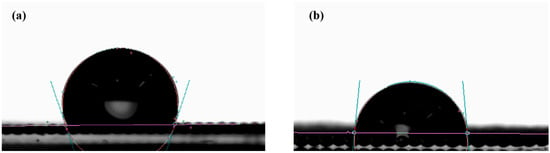
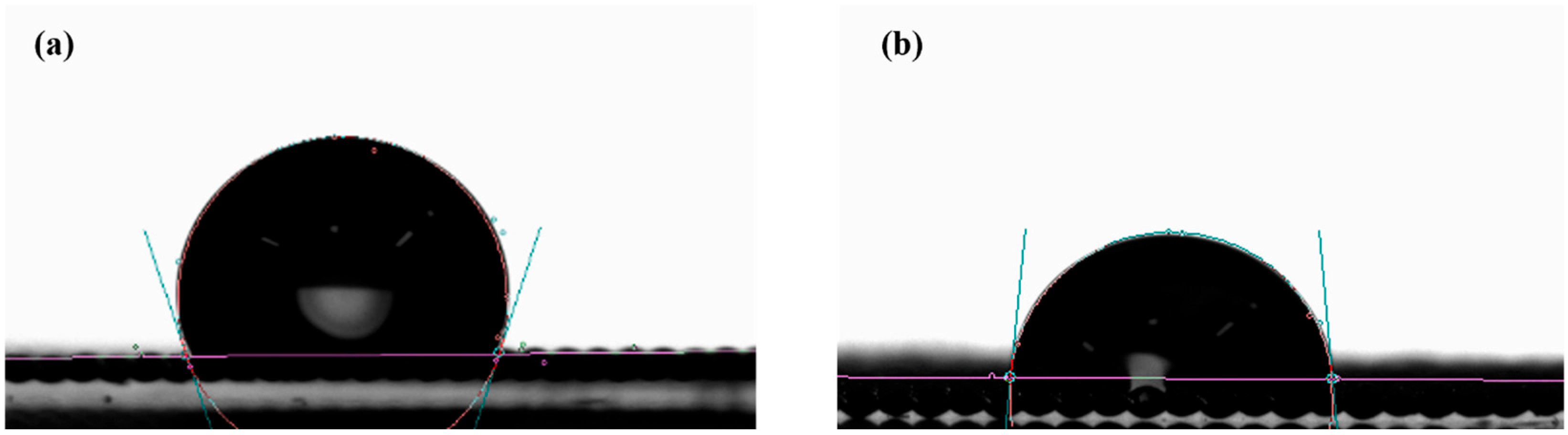
As shown in Figure 4, the contact angle measurements indicated that when no detergent was added (Figure 4a), the Ni(NO3)2 solution exhibited a large contact angle on the surface of the metal-sintered carrier, indicating poor wettability. In contrast, after the addition of the detergent AEO-9 (Figure 4b), the contact angle was significantly reduced, demonstrating a marked improvement in wettability. These results confirmed that the introduction of detergent effectively enhanced the solid–liquid interfacial interaction, enabling the solution to spread rapidly and uniformly over the carrier surface.
Figure 4.
Contact angle of fleece and precursor solution: (a) Ni(NO3)2; (b) Ni(NO3)2 with detergent AEO-9.
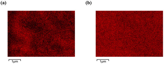
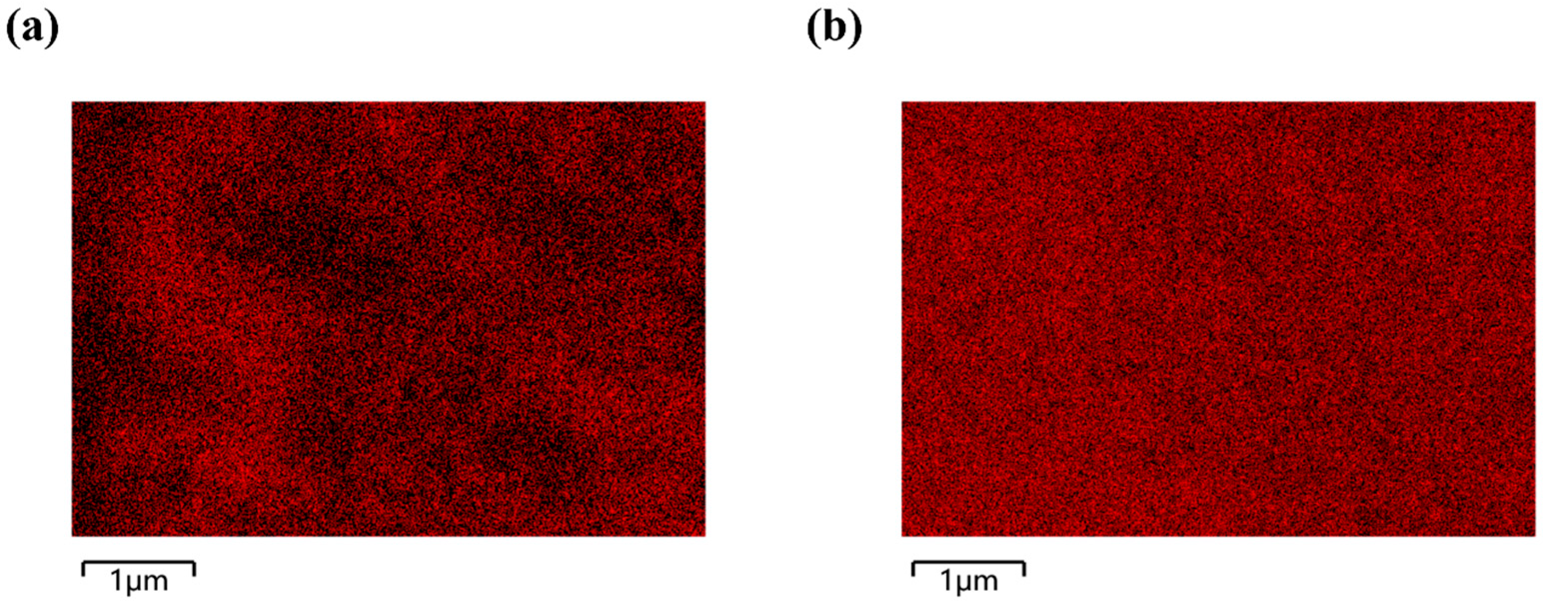
EDS mapping analysis of the impregnated carriers (Figure 5) revealed considerable differences in the Ni distribution. In the sample prepared without the detergent (Figure 5a), the Ni elemental distribution was localized and non-uniform. Conversely, with the addition of the detergent AEO-9 (Figure 5b), Ni(NO3)2 was significantly dispersed more uniformly on the carrier surface. Furthermore, the Ni signal intensity exhibited a gradient decrease from the surface toward the interior of the carrier cross-section, indicating the effective penetration of the precursor solution into the internal pore channels. This improvement in distribution characteristics facilitated the formation of more abundant active sites within the carrier, creating favorable conditions for enhancing the overall performance of the catalyst. According to the reported literature, the mechanism of action of the nonionic surfactant AEO-9 included: (i) reducing the surface tension of the solution, thereby improving the wettability of the support pores [40]; and (ii) during the drying stage, the surfactant molecules inhibited the migration and agglomeration of Ni2+ through steric hindrance effects, thus promoting the formation of smaller and more stable NiO particles. Smaller particle sizes could imply a higher specific surface area of the active phase and a greater number of surface active sites, which is key to the enhancement of catalytic performance [41].
Figure 5.
EDS spectrum of (a) Ni(NO3)2 and (b) Ni(NO3)2 with detergent AEO-9.
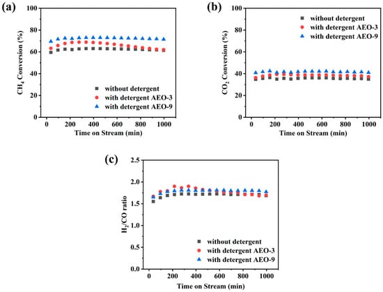
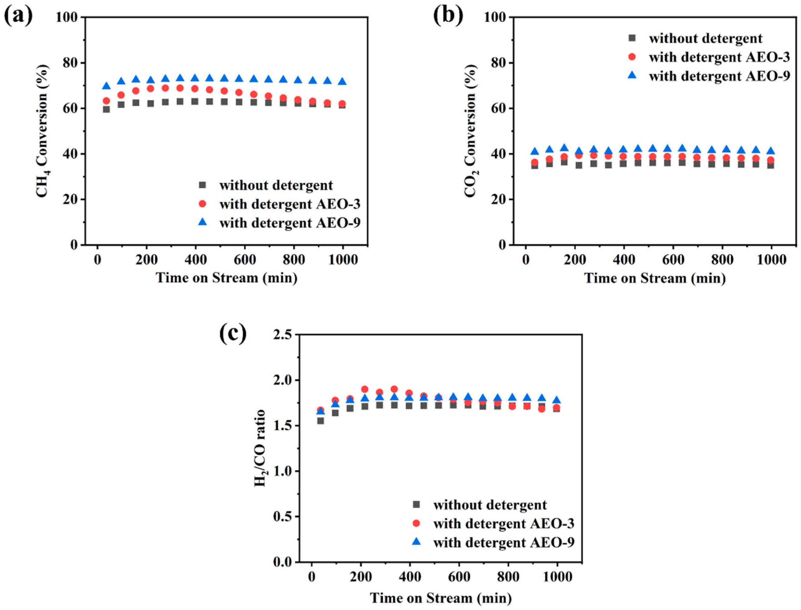
As shown in Figure 6, the performances of the three types of Ni/fleece catalyst in the DRM were systematically compared over time under stable reaction conditions, including calcination at 700 °C, a catalyst loading of 5 g, and a gas hourly space velocity of 1200 NmL/g/h. The catalysts were evaluated without detergent, with detergent AEO-3, and with detergent AEO-9.
Figure 6.
(a) CH4 and (b) CO2 conversion; (c) H2/CO ratio with or without detergent versus time on stream: 700 °C calcination, 700 °C reaction, 1.25 wt% Ni, 1200 NmL/g/h gas hourly space velocity.
By comparing the effects of two detergents with different molecular weights, it was found that both detergent AEO-3 and detergent AEO-9 effectively enhanced the reaction performance compared to the catalyst without detergent. Specifically, for the catalyst with detergent AEO-3, the CH4 conversion stabilized in the range of 62–68%, the CO2 conversion was 36–39%, and the H2/CO ratio remained around 1.8. In contrast, the catalyst with detergent AEO-9 exhibited superior activity and stability, achieving a CH4 conversion of 69–73%, a CO2 conversion of 40–42%, and an equally stable H2/CO ratio of approximately 1.8.
A comparison of the long-term stability of the two detergent revealed that after 1000 min of reaction, the activity of the catalyst with detergent AEO-3 gradually declined to a level comparable to that of the catalyst without detergent, whereas the catalyst with detergent AEO-9 maintained higher catalytic efficiency throughout the entire testing period.
Based on these experimental findings, detergent AEO-9 was selected as the optimal additive for the precursor solution in the subsequent efficient preparation of Ni/fleece catalysts. Since the addition of the detergent to the Ni-based precursor solution was clear and easy, it could be recommended in scale-up applications. An additional simple soaking step could be introduced prior to the loading of catalyst, as the impact on the whole process in terms of extra time and operation would be limited. The increased CO2 and CH4 conversion by several % should merit its extra consideration, as suggested by You et al. [42].
3.1.2. Effect of Calcination Time
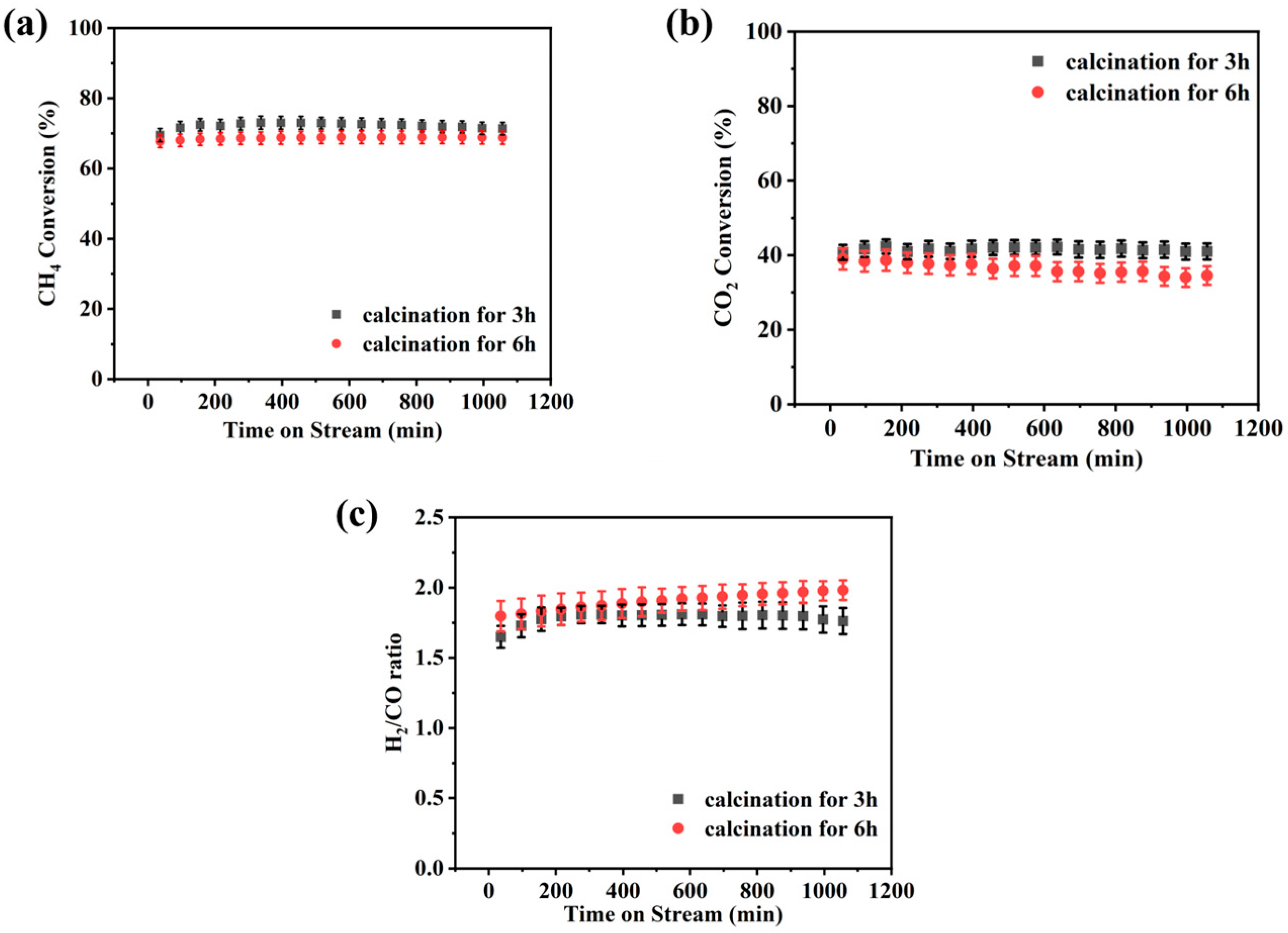
During the preparation of Ni/fleece catalysts, the sintered metamesh carrier was first impregnated with the Ni(NO3)2 solution. The samples were then placed in a tube furnace and calcined in air at 700 °C for 3 and 6 h. After a reduction treatment with H2, their catalytic performances were evaluated under identical reaction conditions by introducing the reaction gas.
The comparative catalytic performance of the catalysts prepared with different calcination durations is presented in Figure 7, with error bars representing the standard deviation of three parallel measurements. In terms of CH4 conversion (Figure 7a), the catalyst calcined for 3 h maintained 71.2 ± 1.1% throughout the reaction. When the calcination time was prolonged to 6 h, the methane conversion rate decreased to 69.4 ± 1.8%, with larger error bars indicating reduced stability. Regarding CO2 conversion (Figure 7b), the sample calcined for 3 h showed stable performance at 41.5 ± 0.8%, while the 6 h calcined sample exhibited lower and more fluctuating conversions (36.2 ± 2.3%). The smaller error bars for the 3 h calcined catalyst suggested better reproducibility and stability. Although the H2/CO ratio (Figure 7c) increased slightly to approximately 2.0 after 6 h of calcination, the catalyst calcined for 3 h demonstrated superior overall reaction efficiency with consistently smaller error bars across all performance indicators.
Figure 7.
(a) CH4 and (b) CO2 conversion; (c) H2/CO ratio with calcination times of 3 and 6 h versus time on stream: 700 °C reaction, 1.25 wt% Ni, 1200 NmL/g/h gas hourly space velocity.
In summary, calcination at 700 °C in air for 3 h was identified as a more suitable pretreatment condition, under which the prepared Ni/fleece catalyst exhibited higher catalytic activity.
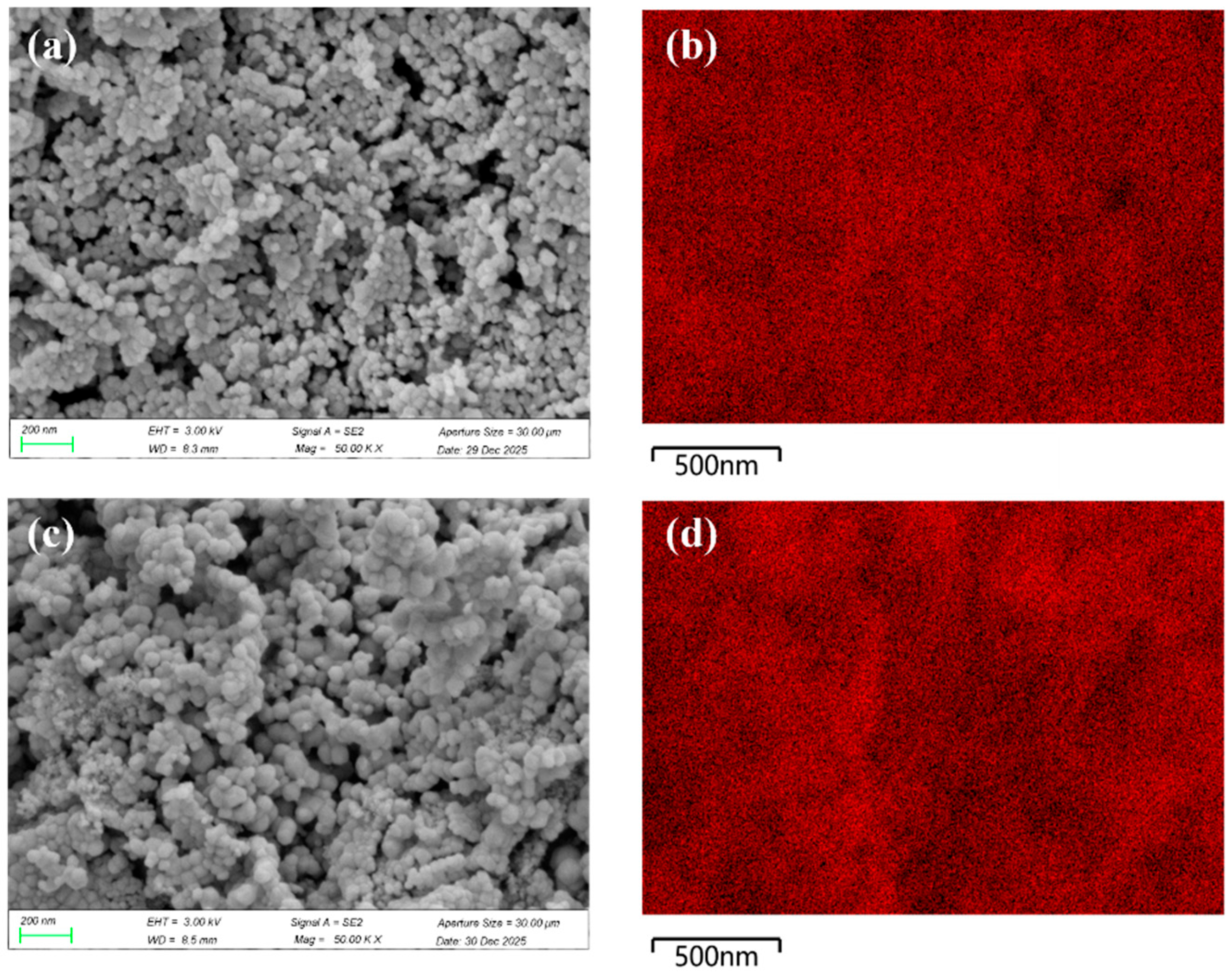
SEM and EDS characterization analyses were performed on the Ni/fleece catalysts calcined at 700 °C under an air atmosphere for 3 and 6 h, with the results presented in Figure 8. The SEM image (Figure 8a) revealed that the catalyst calcined for 3 h exhibited small, densely packed, and uniformly distributed NiO particles on its surface. The corresponding EDS mapping result (Figure 8b) further confirmed a highly uniform dispersion of Ni across the carrier. In contrast, after extending the calcination time to 6 h, the SEM image (Figure 8c) showed significant coarsening of NiO crystallites and the formation of “island-like” aggregates due to sintering. The corresponding EDS analysis (Figure 8d) indicated a clear decline in the uniformity of Ni distribution.
Figure 8.
SEM images and EDS of Ni distribution after calcination: (a,b) 3 h; (c,d) 6 h.
These structural changes aligned well with the previously observed reaction performance, as the reduced activity of the 6 h calcined catalyst can be attributed to a decrease in active surface area and diminished accessibility of active sites, both resulting from the sintering and agglomeration of NiO particles.
3.1.3. Effect of Active Species Loading
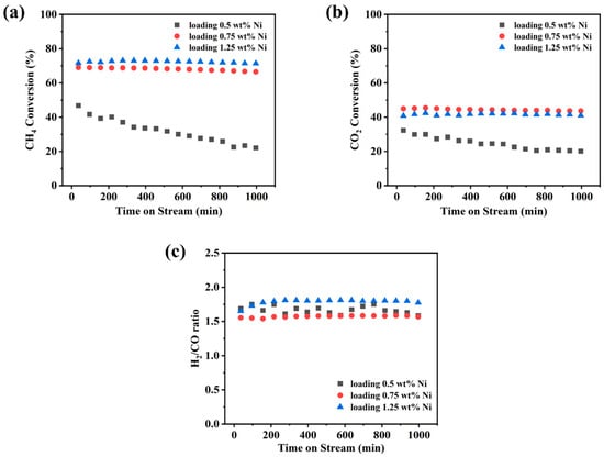
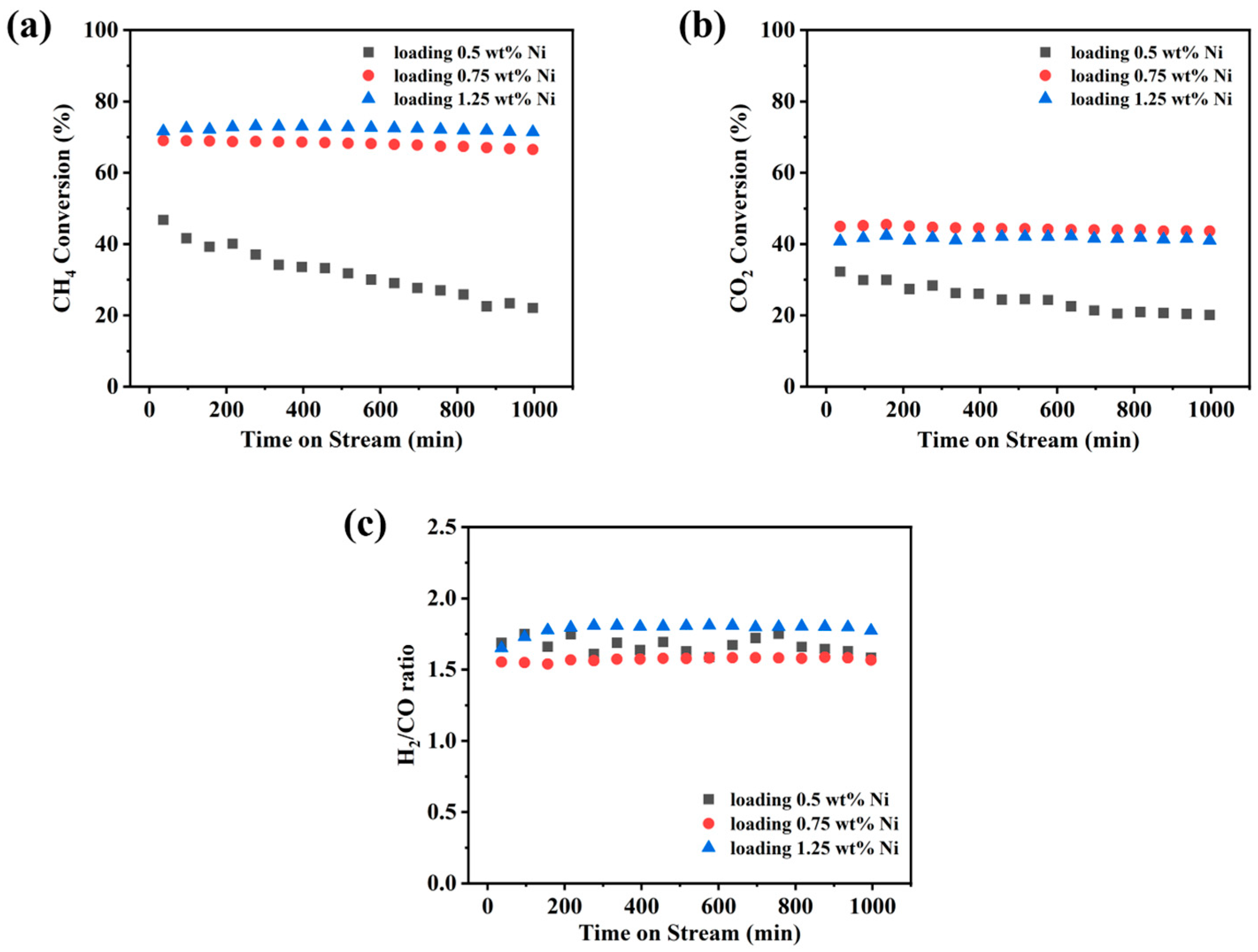
The effect of the metal loading on catalyst performance was studied for Ni loadings (0.5, 0.75, and 1.25 wt%). Their efficiencies for DRM were systematically evaluated and shown in Figure 9.
Figure 9.
(a) CH4 and (b) CO2 conversion; (c) H2/CO ratio with active species loading for 0.5, 0.75, and 1.25 wt% versus time on stream: 700 °C reaction, 1200 NmL/g/h gas hourly space velocity.
The catalyst with a nickel loading of 1.25 wt% exhibited the highest activity, with stable CH4 conversion in the range of 71–73%, CO2 conversion around 42%, and the H2/CO ratio maintained at approximately 1.8. When the loading was reduced to 0.75 wt%, a slight decline in activity was observed: CH4 conversion ranged from 66 to 69%, CO2 conversion was about 44%, and the H2/CO ratio was around 1.55. Conversely, with a further reduction in loading to 0.5 wt%, the catalyst not only showed lower initial activity (CH4 conversion 47%, CO2 conversion 32%), but also demonstrated a pronounced deactivation trend during the 1000 min reaction: CH4 conversion gradually decreased to 22%, CO2 conversion dropped to 20%, and the H2/CO ratio fluctuated between 1.58 and 1.74.
These results indicated that the Ni loading had a significant impact on the catalysts’ stability. For the sample with 0.5 wt% Ni, the initial activity was relatively low and continued to decline over 1000 min of operation, exhibiting typical deactivation behavior. According to the reported literature [43,44], the deactivation of low-loading catalysts under DRM reaction conditions was generally attributed to the following two potential mechanisms: (i) insufficient density of active sites, where the number of Ni active sites per unit area was too low, leading to even trace amounts of carbonaceous species generated during the reaction rapidly covering the entire Ni surface and physically blocking the active sites [45]; (ii) sintering of metal particles, where at extremely low loadings, Ni species may exist as highly dispersed small clusters with high surface energy; however, these clusters are thermodynamically unstable under high-temperature reaction conditions and prone to migration and agglomeration, resulting in a reduction in the number of active sites [46].
In contrast, the catalysts with 0.75 wt% and 1.25 wt% Ni maintained relatively stable activity throughout the reaction, indicating that higher loadings facilitated the formation of a sufficient number of active centers with enhanced resistance to deactivation. Among these, the 1.25 wt% sample exhibited the best performance, which may be attributed to the moderate Ni particle size achieved at this loading, while providing an adequate number of active sites while suppressing sintering and carbon deposition to a certain extent.
3.1.4. Effect of Reduction Conditions
Effect of Reducing Gas
During the activation process of the Ni/fleece catalysts, the influences of different reduction atmospheres (CH4 and H2) on their final catalytic performance were systematically investigated.
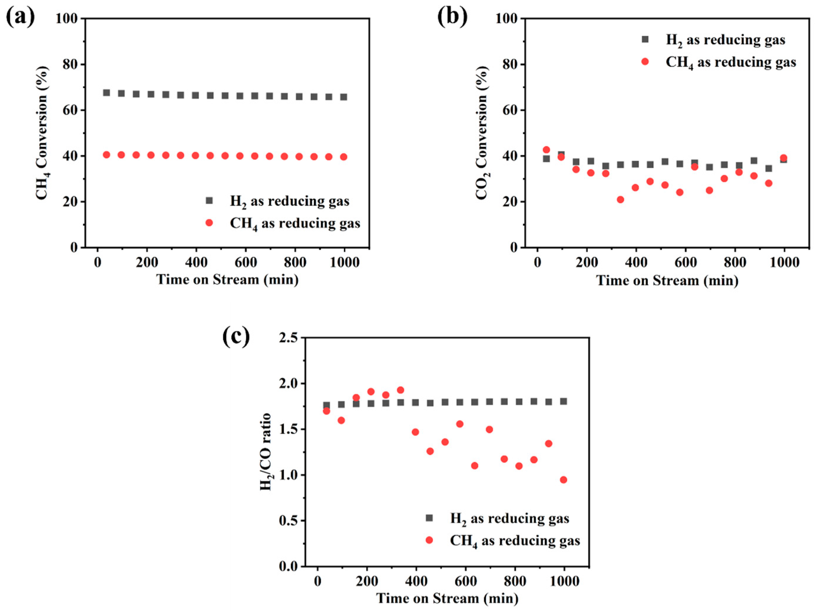
Under the reaction condition of 700 °C, the influences of different reduction atmospheres (H2 and CH4) on the performance of Ni/fleece catalysts are shown in Figure 10. The catalyst reduced in H2 exhibited excellent catalytic stability: CH4 conversion remained stable at 66–67% (Figure 10a), CO2 conversion was maintained between 35 and 40% (Figure 10b), and the H2/CO ratio consistently stayed around 1.8 (Figure 10c). In contrast, the catalyst reduced in CH4 exhibited a strikingly different and more complex behavior: while CH4 conversion remained relatively stable at 39–40%, CO2 conversion fluctuated dramatically within a wide range of 28–42%, and the H2/CO ratio varied drastically between 0.9 and 1.9 (Figure 10). These results suggested that using CH4 as the reducing gas may induce carbon deposition during the reduction process or incomplete reduction on the catalyst surface, which could cover the active sites and alter the reaction pathway, thereby leading to decreased catalyst activity.
Figure 10.
(a) CH4 and (b) CO2 conversion; (c) H2/CO ratio with reducing gas for H2 and CH4 versus time on stream: 700 °C reaction, 1.25 wt% Ni, 1200 NmL/g/h gas hourly space velocity.
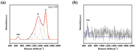
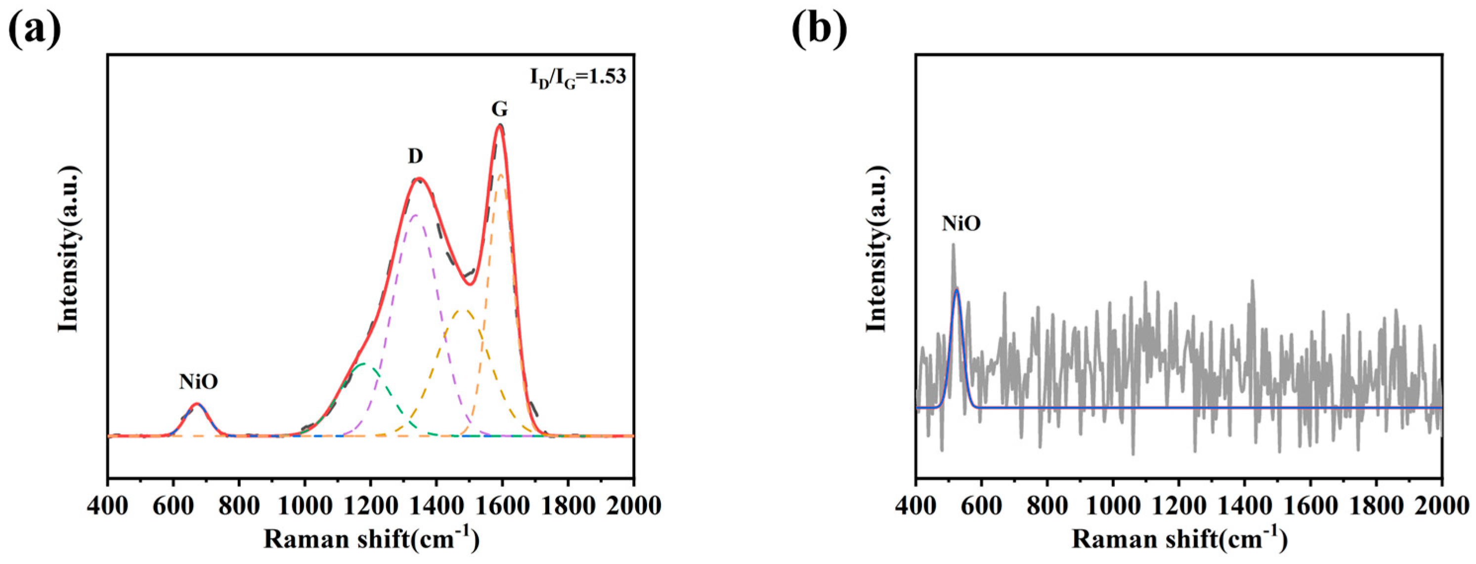
To further investigate the influence of the reducing atmosphere on the surface structure of the catalysts, Raman spectroscopy was performed on the samples activated under different atmospheres. The results are presented in Figure 11. The Raman spectra were fitted with dashed and solid lines represent the experimental data and fitted curves, respectively. For the catalyst reduced in CH4 (Figure 11a), the spectrum exhibits distinct D and G bands at approximately 1350 and 1590 cm−1, respectively, along with several additional weak bands. The ID/IG ratio is determined to be 1.53, indicating the formation of defect-rich amorphous carbon species. Additionally, a peak at 670 cm−1 corresponding to NiO was observed, suggesting an incomplete reduction and the coexistence of Ni0, NiO, and carbon species. In contrast, the H2-reduced catalyst (Figure 11b) showed no characteristic carbon peaks and only a minor NiO feature at 550 cm−1, indicating a predominantly clean metallic surface.
Figure 11.
Raman spectra of Ni/fleece catalysts after different reduction atmosphere treatment: (a) CH4 reduction; (b) H2 reduction.
When correlated with the catalytic performance, these Raman features can point toward distinct dynamic pathways recently identified in Ni-catalyzed DRM [43,47,48,49], thereby providing a mechanistic explanation for the observed differences. For the CH4-reduced catalyst, the coexistence of defect-rich amorphous carbon and residual NiO created a system prone to dynamic instability. The defective carbon actively participated in the reaction via the reverse Boudouard reaction (C + CO2 → 2CO), generating carbon vacancies that continuously captured and released CH4 fragments, while the residual NiO and metallic Ni established a reservoir of interconverting metastable oxygen species (surface atomic oxygen, subsurface oxygen, and bulk NiOₓ) with distinct catalytic activities. Under the DRM feed, this catalyst became trapped in a non-equilibrium oscillatory state, where the sequential transformation of these oxygen species, coupled with the dynamic carbon cycle, led to self-sustained fluctuations in surface chemistry. In this oscillatory regime, CH4 conversion remained relatively stable because a subset of Ni0 sites—likely those regenerated by H2 from CH4 cracking—persistently activated methane. However, CO2 conversion fluctuated dramatically because CO2 activation was exquisitely sensitive to both the dynamic oxygen speciation and the oscillating carbon coverage, with CO2 serving dual roles as a reactant and carbon-removal agent. The corresponding fluctuations in the H2/CO ratio reflected the shifting balance between CH4 cracking and CO2 activation as the surface oscillated between different metastable configurations. For the H2-reduced catalyst, the clean metallic surface with only minor residual NiO allowed the DRM reaction to establish a stable, self-regulating cycle from the outset, converging to a stable attractor state rather than becoming trapped in oscillation.
Based on the integrated results, the choice of reducing gas determined not only the initial surface cleanliness but, more critically, the dynamic trajectory the catalyst followed under reaction conditions. H2 reduction generated a clean metallic surface that could establish a stable reaction pathway, while CH4 reduction created a complex surface architecture that trapped the catalyst in a non-equilibrium oscillatory state. Therefore, H2 was selected as the reducing gas for the activation stage of the Ni/fleece catalyst.
Effect of Reduction Time
To further optimize the reduction process of the Ni/fleece catalyst, the effects of different H2 activation durations on its structure and catalytic performance were systematically investigated.
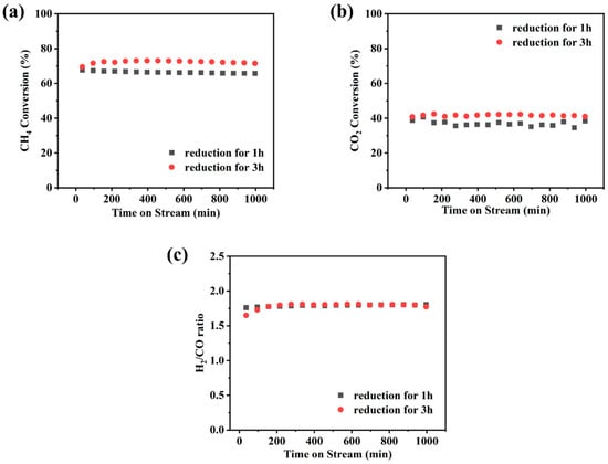
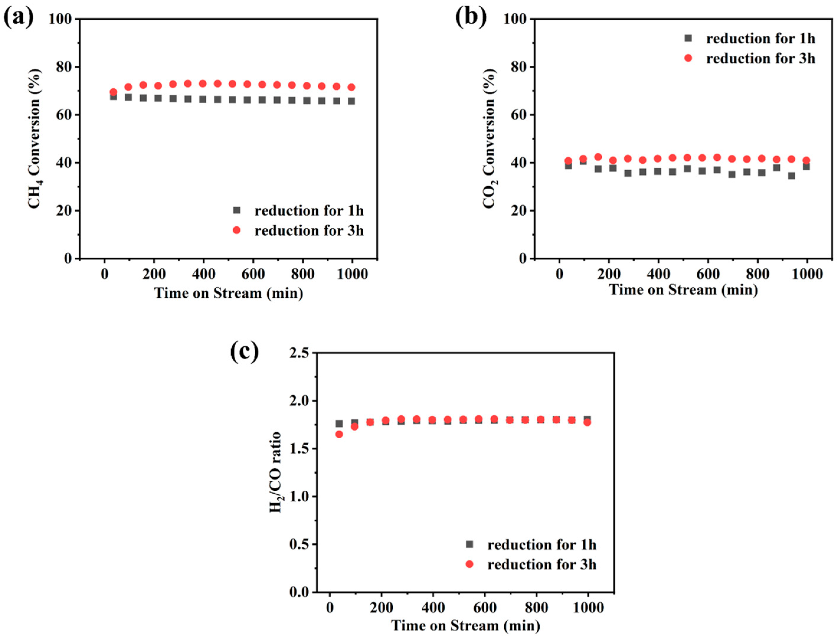
The catalytic performance tests, as presented in Figure 12, showed that under the condition of H2 reduction for 1 h, the CH4 conversion stabilized at 66–67%, the CO2 conversion ranged from 35 to 40%, and the H2/CO ratio was approximately 1.8. When the reduction time was extended to 3 h, the catalyst activity was further enhanced, achieving a CH4 conversion of 70–73% and a CO2 conversion of 41–42%, while the H2/CO ratio remained stable at around 1.8. These results indicated that a longer reduction time was conducive to obtaining higher catalytic activity. This improvement could likely be attributed to a more complete reduction process, which converted a greater amount of NiO into active metallic Ni, thereby providing more abundant active sites.
Figure 12.
(a) CH4 and (b) CO2 conversion; (c) H2/CO ratio with reduction time of 1 and 3 h versus time on stream: 700 °C reaction, 1.25 wt% Ni, 1200 NmL/g/h gas hourly space velocity.
3.1.5. Fleece Before and After Reduction/Reaction
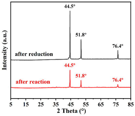
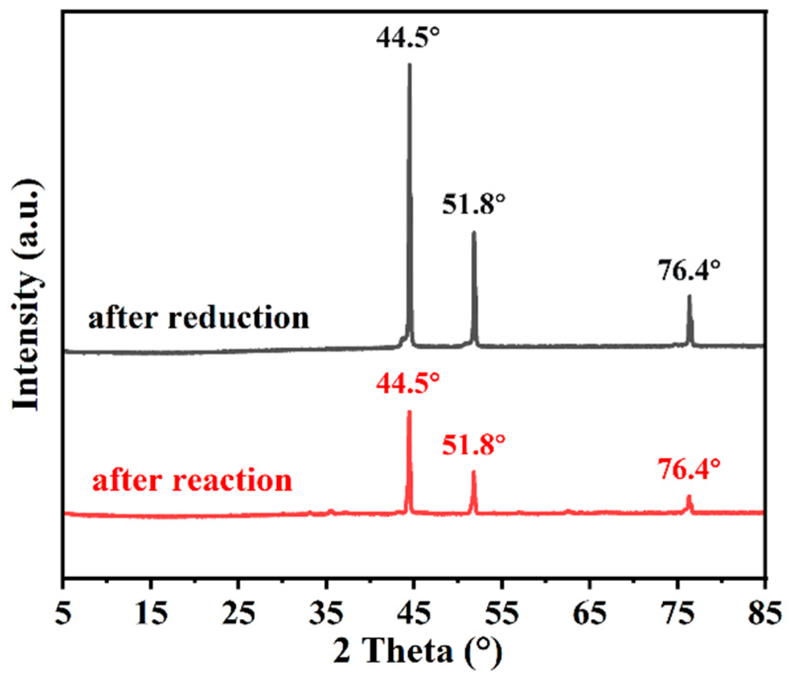
As shown in Figure 13, the values of 2θ = 44.5°, 51.8°, and 76.4° corresponding to Ni (111), (200), and (220), with no impurities appearing, indicated the inert carrier of the catalyst.
Figure 13.
XRD patterns of the Ni/fleece catalyst after reduction and reaction.
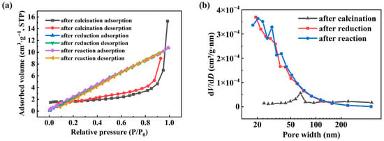
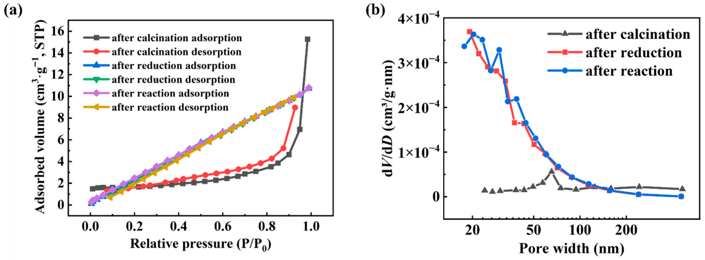
To thoroughly investigate the evolution of the catalyst’s textural properties during the preparation and reaction, nitrogen physisorption was systematically conducted on the samples after calcination (NiO/fleece), after reduction (Ni/fleece), and after reaction. The relevant textural parameters are summarized in Table 2. The isotherms are given in Figure 14.
Table 2.
Physical structure parameters of catalyst loading.
Figure 14.
(a) N2 sorption isotherms and (b) pore size distributions of the catalyst at different stages after calcination, after reduction, and after reaction.
The BET of the bare and etched fleece were 0.024 and 0.52 m2/g, respectively. These low values proved that the fleece fibers were non-porous. With the Ni loading, the Np size, and the wash coat, the increased BET values proved that the wash-coat layer was responsible. Since the fleece was non-porous, pore blocking cannot occur. This finding confirmed earlier findings by Zhang et al. [50].
The data in Table 2 revealed that the reduction treatment was a critical step for optimizing the catalyst’s textural properties. The calcined sample (NiO/fleece) exhibited a relatively low BET specific surface area (5.29 m2/g) and a large average pore diameter (17.85 nm), characteristic of the initial macroporous-dominated structure of the carrier. After H2 reduction, the sample (Ni/fleece) underwent significant textural changes: its specific surface area increased substantially to 18.21 m2/g, while the average pore diameter decreased sharply to 3.64 nm. This transformation indicated that the reduction process not only converted NiO into metallic Ni but may have also involved partial reconstruction of the oxide layer on the carrier surface, thereby exposing a fresher surface and generating a more abundant mesoporous structure. The post-reaction catalyst maintained a similar specific surface area (15.93 m2/g) and pore structure to the reduced sample, demonstrating that the catalyst skeleton remained stable during the prolonged DRM reaction without severe pore blockages or sintering.
The pore size distribution curves (Figure 14b) showed a distinct concentration of mesopores in the range of 20–60 nm for both the reduced and post-reaction samples, which was beneficial for the mass transfer of gaseous molecules in the reaction system. In contrast, the pore size distribution of the calcined sample was relatively broad and dispersed.
In summary, although the metal fleece carrier itself possessed a low specific surface area, its texture was significantly optimized through reduction activation, resulting in a pore system dominated by mesopores that was more conducive to catalysis. The combination of a high specific surface area and a favorable pore structure ensured sufficient exposure of active sites and efficient diffusion of reactants, serving as an important structural foundation for the catalyst’s high activity and stability.
3.2. Effect of the Fleece Support Characteristics
3.2.1. Effect of Pore Size of Filter Layer of Metal Sintering Mesh Carrier
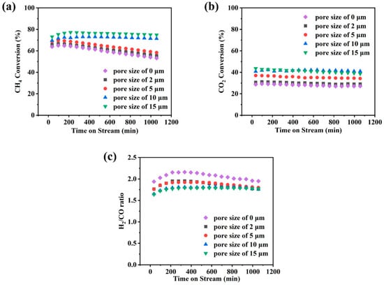
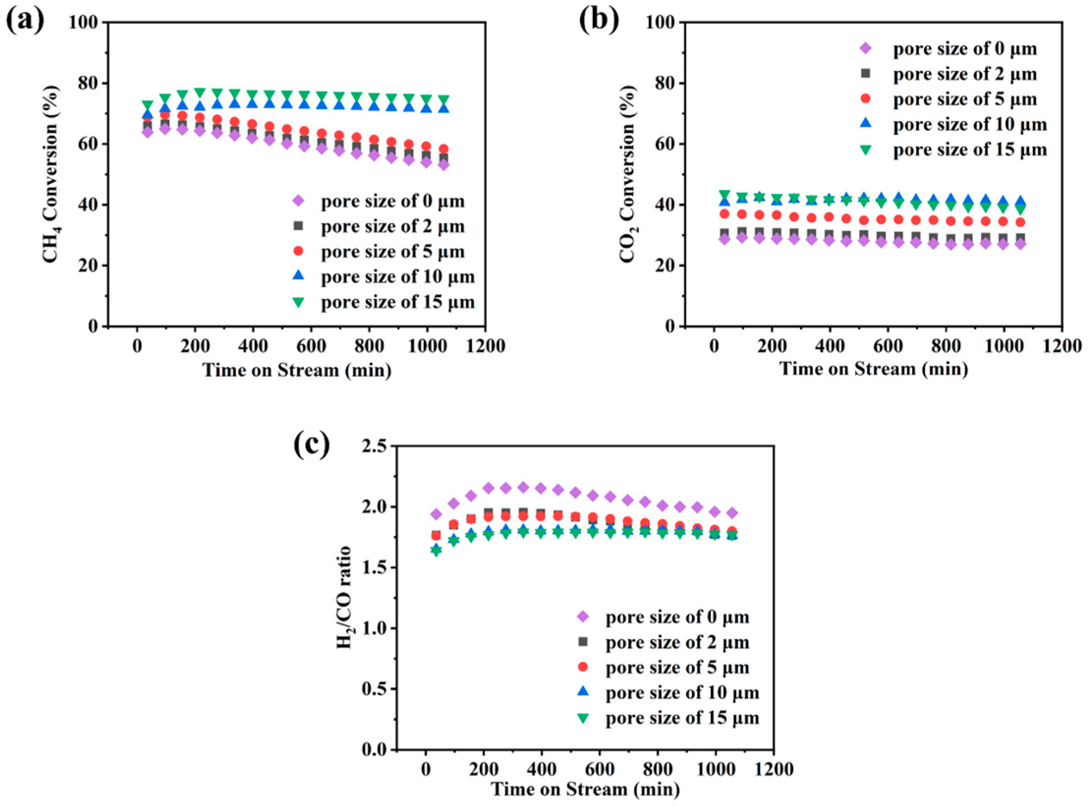
To investigate the influence of the pore size of the metal-sintered mesh carrier filtration layer on the DRM, a series of Ni/fleece catalysts were prepared using carriers with pore sizes of 15, 10, 5, and 2 μm, and another without an intermediate filtration layer (denoted as “0 μm”). Their catalytic performances were evaluated and the results are given in Figure 15.
Figure 15.
(a) CH4 and (b) CO2 conversion; (c) H2/CO ratio with pore sizes of 15, 10, 5, 2, and 0 μm versus time on stream: 700 °C reaction, 1.25 wt% Ni, 1200 NmL/g/h gas hourly space velocity.
The performance test results (Figure 15) showed that the catalyst with a pore size of 15 μm exhibited the best overall performance, maintaining stable CH4 conversion in the range of 73–77%, CO2 conversion of 39–42%, and an H2/CO ratio of approximately 1.8, demonstrating high activity and good stability. When the pore size was reduced to 10 μm, a slight decrease in activity was observed, with CH4 conversion ranging from 70 to 73%, CO2 conversion of 41–42%, and the H2/CO ratio was still around 1.8.
Further reductions in the pore size to 5 μm and below led to significant performance deterioration and accelerated deactivation. For the 5 μm sample, CH4 conversion gradually declined from an initial 69 to 58%, with CO2 conversion between 34 and 37% and an H2/CO ratio around 1.9. The 2 μm sample showed a drop in CH4 conversion from 66 to 55%, CO2 conversion of 29–31%, and an H2/CO ratio of about 1.9. The carrier without a distinct intermediate filtration layer (indicated as “0 μm”) exhibited a decrease in CH4 conversion from 65 to 53%, CO2 conversion of 27–29%, and an H2/CO ratio around 2.0.
Integrating structural and performance analyses, excessively small pore sizes (≤5 μm) severely restricted the mass transfer during the reaction, reducing the accessibility of active sites and exacerbating carbon deposition or sintering, thereby causing activity decline and rapid deactivation. Although the 15 μm carrier demonstrated optimal performance, its fabrication required finer metal wires and a greater amount of wire per unit area, resulting in significantly higher preparation costs compared to carriers with the 10 µm (and smaller) pore sizes.
Based on a comprehensive trade-off between performance and cost, the 10 μm carrier was selected for further in-depth investigation, which showed favorable activity and stability at a more advantageous cost.
3.2.2. Effect of the Number of Fiber Layers of the Sintered Metal Carrier
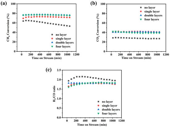
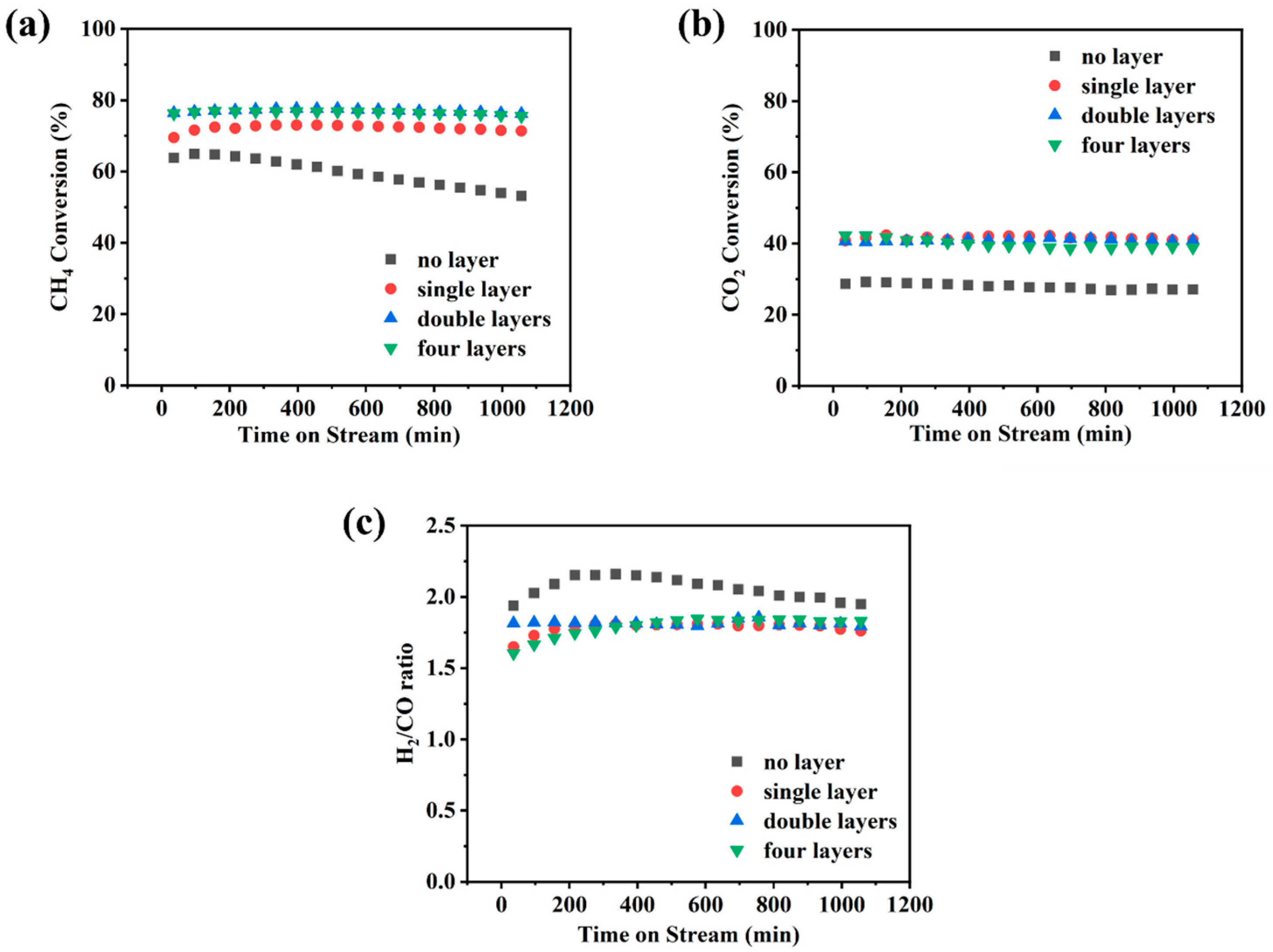
The influence of the number of metal-sintered mesh carrier filtration layers on the performance in DRM was further investigated, with the results presented in Figure 16.
Figure 16.
(a) CH4 and (b) CO2 conversion; (c) H2/CO ratio with filtration layers of 0, 1, 2, and 4 versus time on stream: 700 °C reaction, 1.25 wt% Ni, 1200 NmL/g/h gas hourly space velocity.
When no intermediate filtration layer was present in the carrier, the catalyst exhibited low activity and rapid deactivation: CH4 conversion gradually declined from 65 to 53%, CO2 conversion was only 27–29%, and the H2/CO ratio was approximately 2.0. With the addition of a single filtration layer, performance improved significantly, stabilizing at a CH4 conversion of 70–73%, a CO2 conversion around 41%, and an H2/CO ratio maintained near 1.8. When a double-layer configuration was employed, activity was further enhanced, achieving a CH4 conversion of 76–77% while CO2 conversion remained around 41% and the H2/CO ratio stayed at about 1.8. In contrast, increasing to four layers showed no clear improvement over the double-layer structure, with CH4 conversion (76–77%), CO2 conversion (~40%), and H2/CO ratio (~1.8) remaining comparable.
These results indicated that the introduction of filtration layers effectively improved the reactant distribution and mass transfer, leading to markedly enhanced catalytic activity and stability. However, given the similar performance observed between the double-layer and four-layer configurations, and considering that additional layers substantially increase material costs and bed pressure drop, the double-layer structure was selected for subsequent experiments, which offered excellent overall performance at a more reasonable cost.
3.3. Stability Test of Catalyst
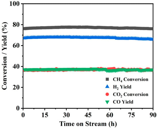
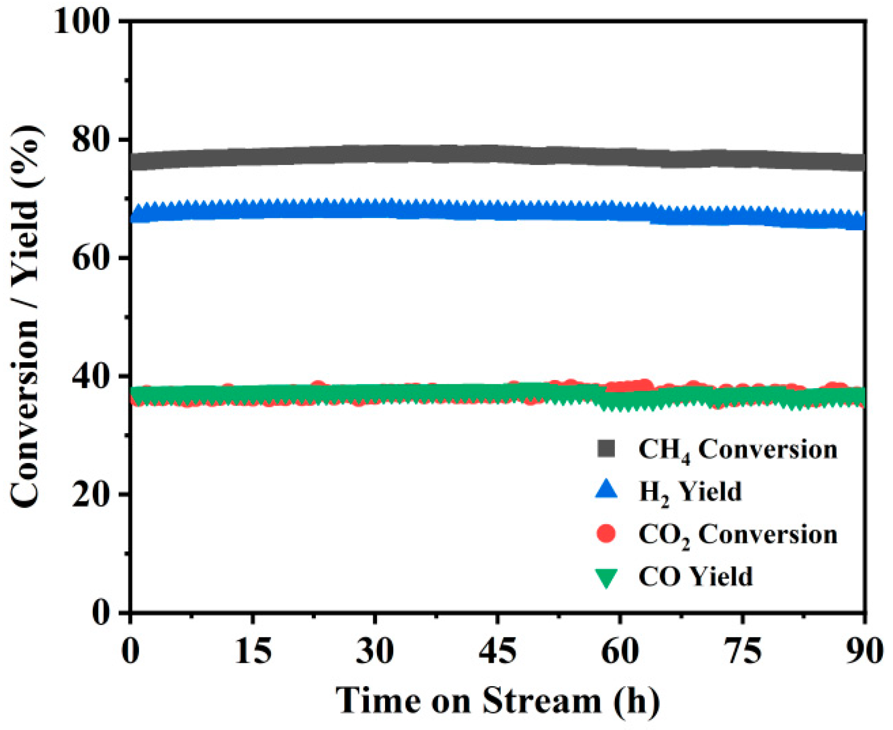
To evaluate the long-term operational stability of the Ni/fleece catalyst, a 90 h lifetime test was conducted under the corresponding reaction conditions. As shown in Figure 17, no significant deactivation was observed throughout the entire test period, with all performance metrics remaining stable: CH4 conversion consistently stayed around 77%, CO2 conversion was stable near 37%, H2 yield was approximately 67%, CO yield about 37%, and the H2/CO ratio maintained around 1.8.
Figure 17.
Conversion and yield versus time on stream: 700 °C reaction, 1.25 wt% Ni, 1200 NmL/g/h gas hourly space velocity.
These results demonstrated (i) that the prepared Ni0/fleece catalyst exhibited good structural stability and catalytic durability in DRM, indicating promising potential for practical application, and (ii) that both CH4 and CO2 conversions exceeded the values obtained in a fixed-bed reactor. Moreover, the fixed-bed operations were prone to higher coking, as reviewed by Deng et al. [51]—carbon-supported Ni has been reported to eliminate coking to a large extent [52].
3.4. Conversion and Yield
3.4.1. Experimental Results
Having applied the findings from the literature to determine the rate equation, it is important to investigate the influence of temperature, T, and catalyst contact time, t, on the conversions and yields—experiments were again performed in triplicate. The deviation in the repeated results and the averages were below 2%. Only the average values were hence applied to the further treatment. The essential data are reported in Table 3 below for both CH4 and CO2 conversions, .
Table 3.
Conversion versus temperature (T) and reaction time (t) [CH4:CO2 = 1:1].
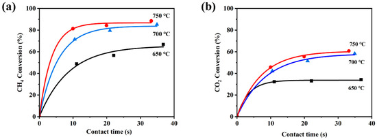
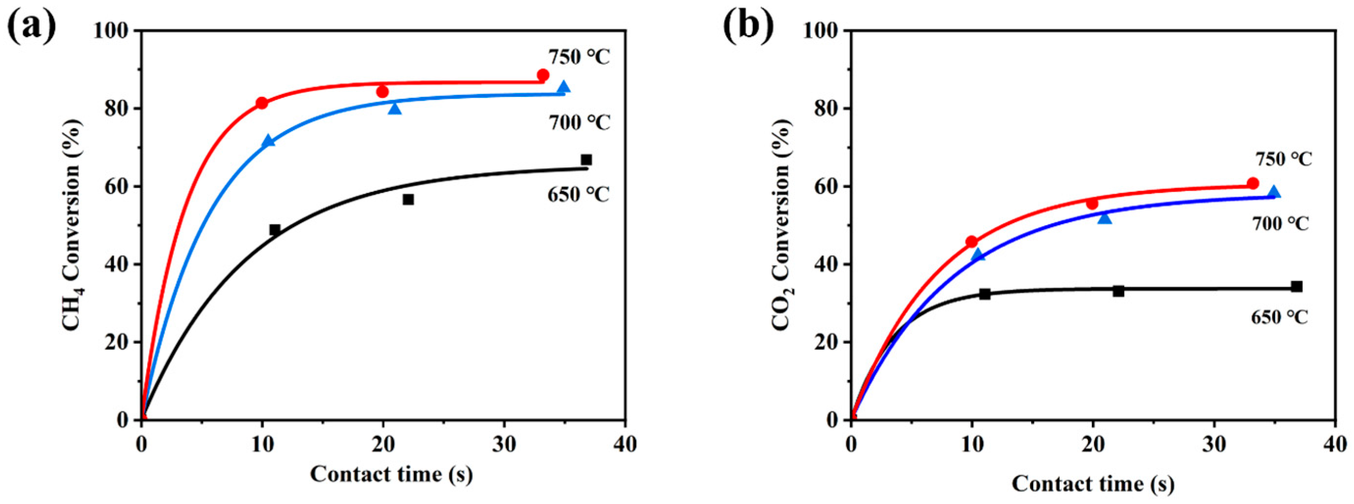
Considering the exponential nature of gas–catalytic first-order reactions, the data were fitted, as illustrated in Figure 18.
Figure 18.
Conversion (a) CH4 and (b) CO2 in function T and t.
The gas velocity through the fleece (with porosity 0.79) was calculated from the total feed flow rate, corrected for temperature T, and divided by the free (open) fleece area:
The contact time was calculated as the ratio of the fleece volume and the gas flow rate at the operating temperature. The free volume of the fleece was determined from its 1.7 mm thickness as 6.22 × 10⁻⁵ m3. Since CH4 was recognized as the RDS, the primary reaction rate can be tentatively presented as a first-order CH4 reaction. The CO2 conversion was stoichiometrically linked with the CH4 conversion, but of a lesser rate-determining step. Both rate reactions allowed the determination of kr1 and kr2 for CH4 and CO2, respectively, as follows:
and varied with temperature, as expected from the Arrhenius expression:
Transforming the results according to Equation (17) can provide the values for the activation energy EA, J/mol, and the pre-exponential factor, Ai, s−1, as reported in Table 4.
Table 4.
Activation energy, EA, and pre-exponential factor, A.
Values of EA and A had a maximum deviation of ±3% on the averages. The Arrhenius expression defined kr, as well as the expected conversion for any set or operating conditions (t, T, , ). Table 4 clearly demonstrates that the CH4 reaction was dominant (high A), whereas the CO2 reaction had a similar EA but a far lower A.
3.4.2. Effect of Space Velocity
The velocity and flow rate data can also be expressed as the ratio of the catalyst weight (see Table 1) and the defined the gas hourly space velocity, GHSV. For all experiments, these can be expressed in NmL/gcat/h and are presented in Table 5.
Table 5.
Reaction condition of GHSV.
At temperature T, the GHSV (in actual mL/g/h) must be multiplied by (T + 273)/273.
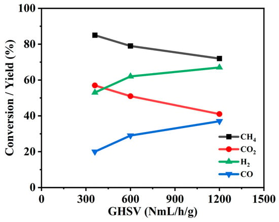
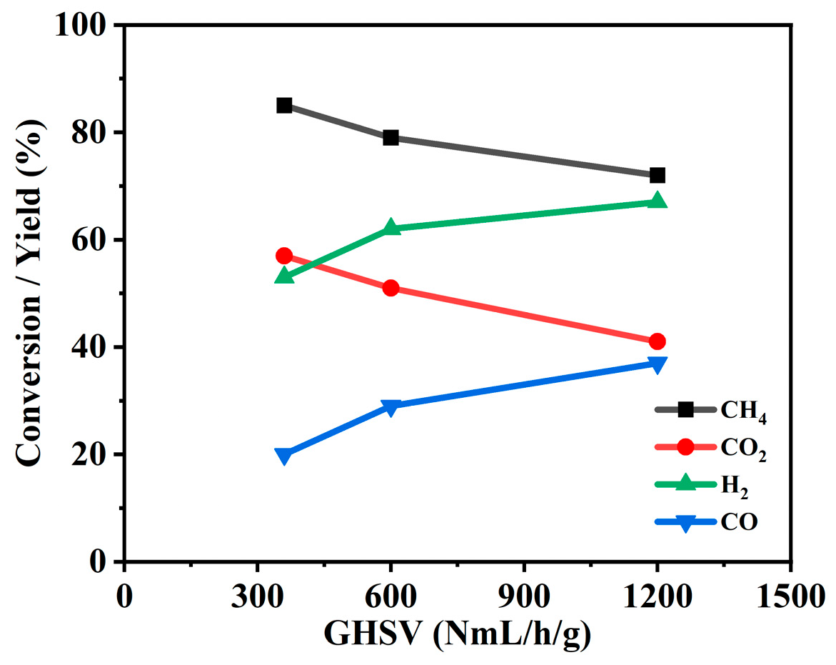
The experimental results are presented in Figure 19.
Figure 19.
Conversion (CH4, CO2) and yield (H2, CO) versus GHSV: 700 °C reaction, 1.25 wt% Ni.
As space velocity decreased, the conversion of reactants progressively increased. At the highest space velocity of 1200 NmL/g/h, CH4 conversion ranged from 70 to 73%, CO2 conversion was 40–42%, H2 and CO yields were 64–67% and 37–39%, respectively, and the H2/CO ratio remained stable around 1.8. When the space velocity was reduced to 600 NmL/g/h, CH4 conversion increased to 74–79% and CO2 conversion reached 46–51%; however, H2 yield declined to 58–62%, CO yield decreased to 27–29%, and the H2/CO ratio correspondingly rose to about 2.0. Upon further decreasing the space velocity to 360 NmL/g/h, although the initial CH4 and CO2 conversions were as high as 86 and 59%, respectively, they exhibited a gradual downward trend during the test period, eventually falling to 81 and 53%. Concurrently, H2 yield was 52–54%, CO yield was only 18–21%, and the H2/CO ratio decreased from an initial value of 3.0 to approximately 2.6.
These results indicated that lower space velocities favored higher reactant conversions but led to decreased yields of H2 and CO, as well as an elevated H2/CO ratio. This trend may be attributed to the occurrence of secondary reactions, such as the reverse water–gas shift reaction or methane cracking, which could lower the selectivity toward the target products or result in further consumption of products due to prolonged residence time in the bed. Therefore, in practical applications, a balanced optimization of space velocity is required, taking into comprehensive consideration conversion efficiency, product distribution, and catalyst stability.
3.4.3. Effect of Temperature
As the reaction temperature increased from 650 to 750 °C, both CH4 and CO2 conversions significantly improved. The results are illustrated Table 3.
At 700 °C, CH4 conversion maintained at 70–85%, CO2 conversion at 42–58%, and the H2/CO ratio stable around 1.8. Upon further increasing the temperature to 750 °C, the initial activity was even higher, reaching a CH4 conversion of 89% and a CO2 conversion of 61%; however, both values gradually decreased during the reaction to 85% and 43%, respectively, while the H2/CO ratio rose to about 2.0.
From a kinetic perspective, raising the temperature facilitated a higher activity for reactant molecules, promoting the rates of elementary reactions such as methane and CO2 reforming, which explained the significant improvement in CH4 and CO2 conversions at elevated temperatures. Concurrently, higher temperatures favored methane cracking to produce H2, leading to an increase in the H2/CO ratio with temperature—a trend consistent with thermodynamic equilibrium. However, the gradual activity decline observed at 750 °C could likely be attributed to two factors: first, accelerated sintering of Ni grain at high temperature; second, although high temperatures helped suppress carbon deposition from CO disproportionation, it may have simultaneously enhanced methane cracking-induced coking (reaction 2). The combined effect of these two deactivation mechanisms could account for the observed slow performance degradation.
3.5. Selectivity
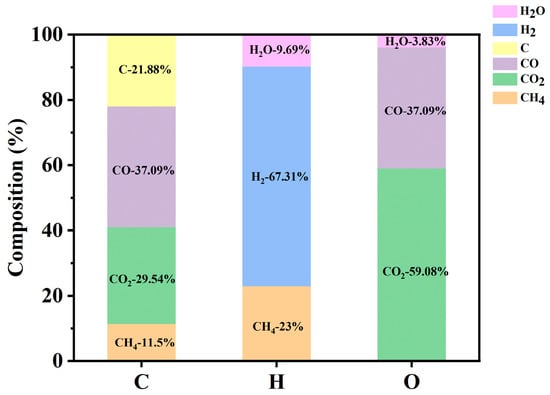
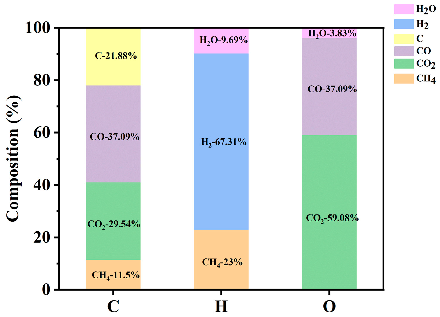
In the elemental selectivity analysis of the outlet gas, a quantitative breakdown of the sources for each element was performed in Figure 20. For carbon, its origin was distributed as follows: 11.5% from the feedstock CH4, 29.54% from CO2, 37.09% from CO, and the remaining 21.88% from other carbon-containing species or deposited carbon. For hydrogen, 23% from CH4, 67.31% from H2, and 9.69% from H2O. For oxygen, 59.08% from CO2, 37.09% from CO, and the remaining 3.83% from H2O.
Figure 20.
Elemental composition of output gas.
4. Scale-Up Recommendations
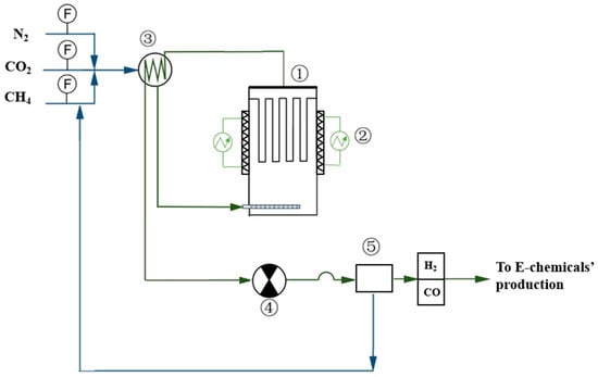
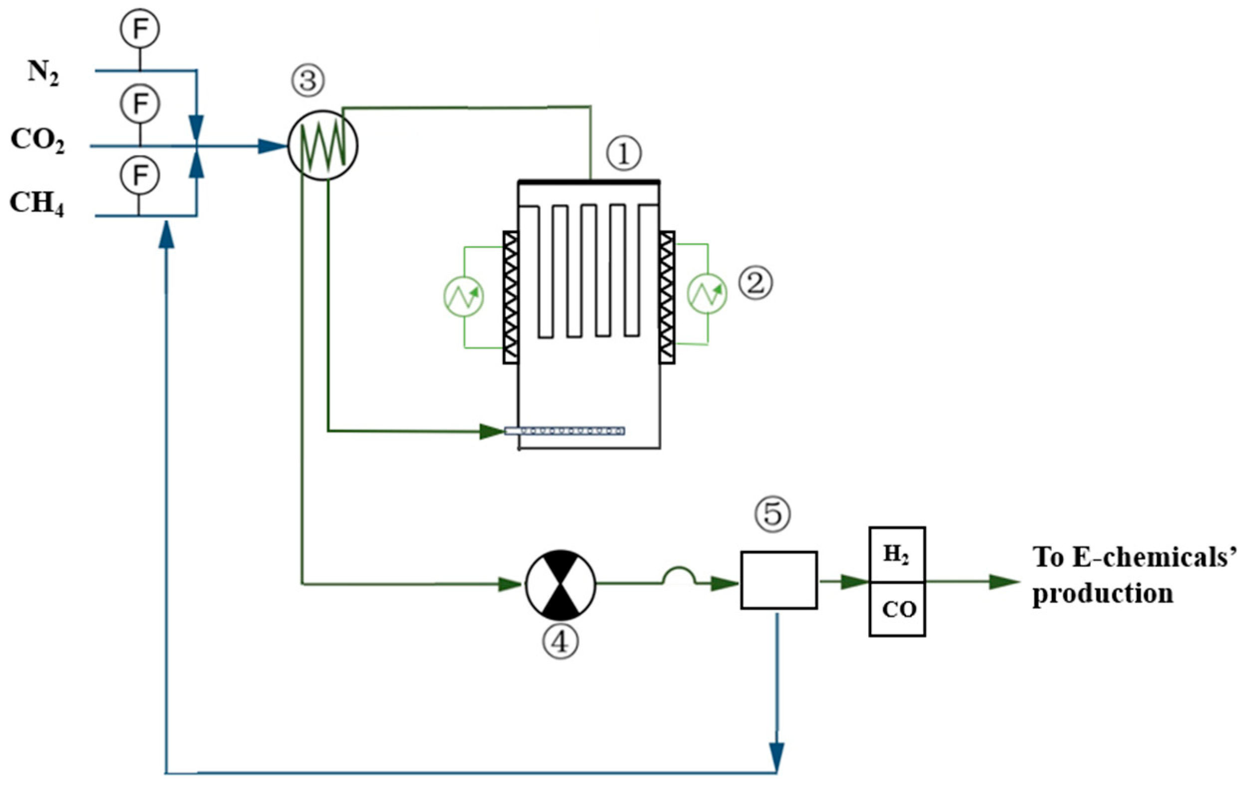
The concept of using a fleece candle as a catalyst carrier could facilitate the upscaling to industrial capacities. Not only can several candles be installed in a single reactor vessel and operated in parallel, but candles of diameter to 0.15 m and length to 3 m can be supplied. If a long contact time is required, the fleece thickness can be increased to 30 mm, thus allowing higher active species loadings, and again increasing the gas/catalyst contact time at a given surface gas flow rate. Experiments are currently ongoing with fleece candles of decreasing diameter mounted in the outer fleece of the longer diameter.
With a higher catalyst loading, the GHSV value obtained on laboratory scale could define the reaction yield. During the lab-scale experiments, some coking occurred (as monitored by the fleece ΔP). The DRM reaction was then stopped, and air was fed at 700 °C to burn the coke layer. When the ΔP was restored, the DRM was restarted. This was deemed necessary after about 90 h on stream.
The challenges for future scale-up will include the design and manufacturing of a multi-orifice distributor that can uniformly feed all parallel candles. Although the ΔP of the lab-scale candle was 6 Pa only, thicker or series fleeces will increase the working pressure, although this increase would be proportional with the fleece thickness since the flow mode is laminar. From a sustainability perspective, the final step could involve separating non-reacted CH4 and CO2 from the syngas product stream using techniques such as adsorption/desorption, membrane separation, or other equivalent methods. Crucially, this separated residual gas stream would not be discarded but rather recycled directly back to the reactor inlet. This closed-loop recycling strategy could significantly improve the overall raw material utilization rate, reduce feedstock consumption, and minimize greenhouse gas emissions. By converting unreacted gases back into valuable products, the process embodies the principles of a circular economy and could contribute to the environmental sustainability of the DRM technology.
The proposed scale-up fleece reactor is depicted in Figure 21. With these merits of the proposed technology, and the constant long-duration conversion results obtained, the objectives of Section 1.3 were deemed to be met.
Figure 21.
Proposal setup for fleece–DRM. ① Fleece reaction with tubular feedstock distributor; ② electrical heating; ③ feedstock preheater; ④ exhaust fan; ⑤ adsorption/desorption of residual CO2 + CH4 with recycle to feedstock, and F, mass flow.
5. Conclusions
Biogas, typically composed of approximately 50 vol% CO2 and 50 vol% CH4, serves as an ideal and sustainable feedstock for the dry reforming of methane (DRM), transforming waste-derived resources into valuable syngas. Ni0 has been proven to be a good catalyst at low (0.5–1.25 wt%) loading of the carriers. In contrast to conventional fixed-bed reactors, a novel through-flow fleece reactor was developed and proven to offer both high effectiveness and operational efficiency, achieving very high conversions of CO2 and CH4. The optimal loading of active species on the sintered metal fleece was achieved (i) by adding detergent to the Ni-solution and (ii) through precise control of calcination and reduction conditions. Although a limited amount of coking was observed, the catalyst could be readily regenerated via offline combustion, restoring its activity and extending its service life—an important feature for process sustainability and economic viability. Owing to its simple configuration, the catalyst fleece reactor could be easily scalable for industrial applications. To further mitigate the slight coking observed during prolonged DRM operation, there is ongoing research investigating the addition of small amounts of zeolites or SAPO-11 to the catalyst precursor to enhance the Brønsted acidity of the active sites, thereby improving long-term stability and resource efficiency.
Supplementary Materials
The following supporting information can be downloaded at: https://www.mdpi.com/article/10.3390/su18063151/s1, Figure S1: Geometry and dimensions of (a) the fleece reactor; (b) the fleece candle; Table S1: Analytical parameter and tools.
Author Contributions
Investigation, F.C.; Validation, F.C. and Y.J.; Resources, H.Z.; Formal Analysis, F.C., J.B., Y.J. and Z.L.; Writing—Original Draft, F.C. and J.B.; Writing—Review and Editing, all authors; Visualization, F.C. and H.Z.; Supervision, H.Z. All authors have read and agreed to the published version of the manuscript.
Funding
This research received no external funding.
Institutional Review Board Statement
Not applicable.
Informed Consent Statement
Not applicable.
Data Availability Statement
The original contributions presented in this study are included in the article/Supplementary Material. Further inquiries can be directed to the corresponding authors.
Acknowledgments
All authors would like to express their gratitude to the Beijing Advanced Innovation Center for Soft Matter Science and Engineering of Beijing University of Chemical Technology.
Conflicts of Interest
The authors declare no conflicts of interest.
Abbreviations
The following abbreviations are used in this manuscript:
| DRM | dry reforming of methane |
| ∆H | enthalpy change in chemical reaction |
| T | temperature |
| P | pressure |
| F | mass flow |
| AEO-3 | RO(CH2CH2O)nH, R=C12–16 alkyl, n = 3 |
| AEO-9 | RO(CH2CH2O)nH, R=C12–16 alkyl, n = 9 |
| BET | Brunauer–Emmett–Teller specific surface area test method |
| SEM | scanning electron microscope |
| EDS | energy dispersive spectroscopy |
| XRD | X-ray diffraction |
| GHSV | gas hourly space velocity |
References
- Ou, Y.; Iyer, G.; Fawcett, A.; Hultman, N.; McJeon, H.; Ragnauth, S.; Smith, S.J.; Edmonds, J. Role of non-CO2 greenhouse gas emissions in limiting global warming. One Earth 2022, 5, 1312–1315. [Google Scholar] [CrossRef] [Scilit]
- He, J.; Huang, B. Estimating global anthropogenic CO2 emissions through satellite observations. Environ. Res. 2025, 279, 121767. [Google Scholar] [CrossRef] [Scilit]
- Sheng, M.; Hou, Y.; Song, H.; Ye, X.; Lei, L.; Ma, P.; Zeng, Z.-C. Estimating anthropogenic CO2 emissions from China’s Yangtze River Delta using OCO-2 observations and WRF-Chem simulations. Remote Sens. Environ. 2025, 316, 114515. [Google Scholar] [CrossRef] [Scilit]
- Baena-Moreno, F.M.; Pastor-Pérez, L.; Wang, Q.; Reina, T.R. Bio-methane and bio-methanol co-production from biogas: A profitability analysis to explore new sustainable chemical processes. J. Clean. Prod. 2020, 265, 121909. [Google Scholar] [CrossRef] [Scilit]
- Yang, M.; Vander Elst, M.; Smets, I.; Zhang, H.; Li, S.; Baeyens, J.; Deng, Y. Reviewing Improved Anaerobic Digestion by Combined Pre-Treatment of Waste-Activated Sludge (WAS). Sustainability 2024, 16, 6419. [Google Scholar] [CrossRef] [Scilit]
- Deng, Y.; Baeyens, J.; Elst Margot, V.; Liu, H. Renewable electricity and “green” feedstock-based chemicals will foster industrial sustainability. Innov. Energy 2024, 1, 100016. [Google Scholar] [CrossRef] [Scilit]
- Zhang, C.; Su, H.; Baeyens, J.; Tan, T. Reviewing the anaerobic digestion of food waste for biogas production. Renew. Sustain. Energy Rev. 2014, 38, 383–392. [Google Scholar] [CrossRef] [Scilit]
- Liu, Q.; Wu, L.; Jackstell, R.; Beller, M. Using carbon dioxide as a building block in organic synthesis. Nat. Commun. 2015, 6, 5933. [Google Scholar] [CrossRef] [Scilit]
- Zhao, Y.; Zhai, R.; Liu, S.; Xu, Y.; Liu, L. Low carbon economic scheduling of integrated energy system with concentrating solar power and multi-stage hydrogen utilization based on ladder-type carbon trading. Int. J. Green Energy 2025, 22, 722–739. [Google Scholar] [CrossRef] [Scilit]
- Deng, Y.; Dewil, R.; Appels, L.; Van Tulden, F.; Li, S.; Yang, M.; Baeyens, J. Hydrogen-enriched natural gas in a decarbonization perspective. Fuel 2022, 318, 123680. [Google Scholar] [CrossRef] [Scilit]
- Apolinar-Hernández, J.E.; Bertoli, S.L.; Riella, H.G.; Soares, C.; Padoin, N. An Overview of Low-Temperature Fischer–Tropsch Synthesis: Market Conditions, Raw Materials, Reactors, Scale-Up, Process Intensification, Mechanisms, and Outlook. Energy Fuels 2024, 38, 1–28. [Google Scholar] [CrossRef] [Scilit]
- Usman, M.; Wan Daud, W.M.A.; Abbas, H.F. Dry reforming of methane: Influence of process parameters—A review. Renew. Sustain. Energy Rev. 2015, 45, 710–744. [Google Scholar] [CrossRef] [Scilit]
- Yu, S.; Li, C.; Lyu, L.; Cai, R.; Xiao, L.; Jiao, Y.; Chen, H.; Ou, X.; Wei, X.; Fan, X. Development of a fluidized bed reactor for catalytic dry reforming of methane with CO2. Carbon Capture Sci. Technol. 2025, 17, 100540. [Google Scholar] [CrossRef] [Scilit]
- Wittich, K.; Krämer, M.; Bottke, N.; Schunk, S.A. Catalytic Dry Reforming of Methane: Insights from Model Systems. ChemCatChem 2020, 12, 2130–2147. [Google Scholar] [CrossRef] [Scilit] [PubMed]
- Zhu, J.; Peng, X.; Yao, L.; Deng, X.; Dong, H.; Tong, D.; Hu, C. Synthesis gas production from CO2 reforming of methane over Ni–Ce/SiO2 catalyst: The effect of calcination ambience. Int. J. Hydrogen Energy 2013, 38, 117–126. [Google Scholar] [CrossRef] [Scilit]
- Gutiérrez, M.C.; Hernández, P.S.; Anzures, F.M.; Martínez, A.G.; Galicia, G.M.; Fernández García, M.E.; Escobar-Alarcón, L.; Tzompantzi Morales, F.J.; Pérez-Hernández, R. MgO impregnation to Al2O3 supported Ni catalyst for SYNGAS production using greenhouse gases: Some aspects of chemical state of Ni species. Int. J. Hydrogen Energy 2024, 52, 1131–1140. [Google Scholar] [CrossRef] [Scilit]
- Cherbański, R.; Murgrabia, S.; Kotkowski, T.; L’Hospital, V.; Molga, E.; Stankiewicz, A. Dry reforming of methane: Thermodynamic, kinetic and catalyst coking investigations. Int. J. Hydrogen Energy 2026, 212, 153769. [Google Scholar] [CrossRef] [Scilit]
- Abdulai, Y.N.; Yusuf, B.O.; Hussain, I.; Okeyode, A.H.; Abdullahi, A.S.; Alhooshani, K.R.; Ganiyu, S.A. Tailoring acid–base properties in Ni/ZSM-5 catalysts via sequential ion exchange and surface modification for stable dry reforming of methane. Mol. Catal. 2026, 594, 115819. [Google Scholar] [CrossRef] [Scilit]
- Algarni, T.S.; Jumah, A.b.; Acharya, K.; Osman, A.I.; Ahmed Ali, F.A.; Alreshaidan, S.B.; Odhah, O.H.; Al-Anazi, A.; Kumar, R.; Al-Fatesh, A.S. Samarium’s synergistic impact on Ni/Al for effective methane dry reforming: Promoter loading and process optimization. Fuel 2026, 407, 137414. [Google Scholar] [CrossRef] [Scilit]
- Alshammari, D.A.; Ibrahim, A.A.; Ali, F.A.; AbdElhafez, S.E.; El Marouani, M.; El-Naggar, N.A.; Alharbi, F.S.; Alsayed, A.A.; Al-Fatesh, A.S. Governing the Efficiency of Ni/SiO2-Al2O3 Catalyst for Methane Dry Reforming via Strategic Calcination Conditions. Catalysts 2026, 16, 118. [Google Scholar] [CrossRef] [Scilit]
- Cui, T.; Chen, Q.; Zhang, Y.; Nie, B.; Yang, B. Structural sensitivity analysis of Ni-based catalysts for the dry reforming of methane with balanced activity and stability. Appl. Surf. Sci. 2026, 731, 166421. [Google Scholar] [CrossRef] [Scilit]
- Sun, S.; Li, D.; Liu, H.; Wang, C.; Zhao, M.; Hou, H.; Zhao, Y.; Zhang, Q.; He, D.; Lei, Y. Pivotal strategies towards stable Ni-based catalysts for dry reforming of methane: Resisting carbon accumulation. J. Catal. 2026, 455, 116671. [Google Scholar] [CrossRef] [Scilit]
- Shao, B.; Wang, Z.-Q.; Gong, X.-Q.; Liu, H.; Qian, F.; Hu, P.; Hu, J. Synergistic promotions between CO2 capture and in-situ conversion on Ni-CaO composite catalyst. Nat. Commun. 2023, 14, 996. [Google Scholar] [CrossRef] [Scilit]
- Kwon, J.H.; Lee, S.; Park, K.S.; Soh, B.-W.; Kim, K.; Bae, J.W. NiCe@SiO2 core-shell-structured catalyst for an enhanced thermal stability for dry reforming of CH4 with CO2. Appl. Catal. B Environ. Energy 2026, 387, 126510. [Google Scholar] [CrossRef] [Scilit]
- Veselov, G.B.; Ilyina, E.V.; Stoyanovskii, V.O.; Vedyagin, A.A. Dry reforming of methane over Ni-Mg-O and Ni-Ce-Mg-O oxide catalysts: Effect of the calcination temperature on the catalytic performance and thermal stability. Appl. Catal. A Gen. 2026, 713, 120801. [Google Scholar] [CrossRef] [Scilit]
- Wang, D.; Liu, J.; Che, Y.; Yang, H.; Li, B.; Su, T.; Zhang, J. Steam-assisted dry reforming of methane over a Ce-doped Ni/calcium aluminate catalyst enabling stable syngas production. Fuel 2026, 418, 138766. [Google Scholar] [CrossRef] [Scilit]
- Tang, W.; Cao, J.-P.; Zhao, X.-Y.; Xie, D.; Luan, K.-R.; Li, C.-J.; She, Q.-M.; Bold, T. Relationship of catalytic performance and catalyst structure evolution based on pressurized CH4-CO2 reforming reaction over carbon-supported Co-Ir alloy catalysts. Fuel 2026, 414, 138320. [Google Scholar] [CrossRef] [Scilit]
- Wang, L.; Hong, J.; Yang, W.; Liang, Y.; Vila, F.; Hu, J.; Chang, H.; Tao, Y.; Wang, Z.; Haynes, B.S.; et al. Highly Stable Supported Cu–Ni Dilute Alloy Catalyst for Efficient CO2 Reforming of Methane. J. Am. Chem. Soc. 2026, 148, 5606–5614. [Google Scholar] [CrossRef] [Scilit]
- Wang, Q.; Shen, C.; Zhang, J.; Wang, J.; Liu, C.; Wang, X.; Ding, W.; Guo, X. Electron-deficient Ni0 sites stabilized by dual Ni/MgNiO2 interface enable efficient and durable dry reforming of methane. Appl. Catal. B Environ. Energy 2026, 383, 126105. [Google Scholar] [CrossRef] [Scilit]
- Wang, T.; Xu, C.; Xia, G.; Wen, F.; Zhang, R.; Deng, J.; Li, H. Rare-earth–modulated ordered mesoporous MgAl2O4 enabling ultra-stable Ni catalysts for methane dry reforming. J. Energy Inst. 2026, 125, 102460. [Google Scholar] [CrossRef] [Scilit]
- Zhang, Z.-Y.; Su, D.-M.; Li, R.-T.; Feng, C.-Y.; Luo, L.; Yang, G.-D.; Xie, T. Defect engineering based on lattice plane oriented growth in Ru-Ceria system for photo-thermal catalytic methane dry reforming. Carbon Neutrality 2026, 5, 2. [Google Scholar] [CrossRef] [Scilit]
- Bradford, M.C.J.; Vannice, M.A. Catalytic reforming of methane with carbon dioxide over nickel catalysts II. Reaction kinetics. Appl. Catal. A Gen. 1996, 142, 97–122. [Google Scholar] [CrossRef] [Scilit]
- Zhang, Z.; Verykios, X.E. Mechanistic aspects of carbon dioxide reforming of methane to synthesis gas over Ni catalysts. Catal. Lett. 1996, 38, 175–179. [Google Scholar] [CrossRef] [Scilit]
- Nandini, A.; Pant, K.K.; Dhingra, S.C. Kinetic study of the catalytic carbon dioxide reforming of methane to synthesis gas over Ni-K/CeO2-Al2O3 catalyst. Appl. Catal. A Gen. 2006, 308, 119–127. [Google Scholar] [CrossRef] [Scilit]
- Hayes, R.E.; Kolaczkowski, S.T. Introduction to Catalytic Combustion; Gordon and Breach Science Publishers: Amsterdam, The Netherlands, 1997. [Google Scholar]
- Kroll, V.C.H.; Swaan, H.M.; Lacombe, S.; Mirodatos, C. Methane Reforming Reaction with Carbon Dioxide over Ni/SiO2 Catalyst: II. A Mechanistic Study. J. Catal. 1996, 164, 387–398. [Google Scholar] [CrossRef] [Scilit]
- Zhang, J.; Wang, H.; Dalai, A.K. Kinetic Studies of Carbon Dioxide Reforming of Methane over Ni–Co/Al–Mg–O Bimetallic Catalyst. Ind. Eng. Chem. Res. 2009, 48, 677–684. [Google Scholar] [CrossRef] [Scilit]
- Wei, J.; Iglesia, E. Isotopic and kinetic assessment of the mechanism of reactions of CH4 with CO2 or H2O to form synthesis gas and carbon on nickel catalysts. J. Catal. 2004, 224, 370–383. [Google Scholar] [CrossRef] [Scilit]
- Yang, M.; Gao, W.; Zhang, H.; Li, S.; Mikulčič, H.; Baeyens, J. Catalytic methane decomposition on an Fe-catalyst, coated on a novel fleece reactor. Energy 2025, 335, 138340. [Google Scholar] [CrossRef] [Scilit]
- Zhang, S.; Wang, F.; Tan, B.; Wang, Y.; Liu, P.; Kim, T.; Guo, L.; Han, X.; Liu, R. Enhanced particle removal ability of two representative nonionic surfactants: A reasonable interpretation based on DFT and coarse-grained molecular dynamics methods. J. Mol. Liq. 2024, 413, 125984. [Google Scholar] [CrossRef] [Scilit]
- Pour, A.N.; Hosaini, E.; Izadyar, M.; Housaindokht, M.R. Particle size effects in Fischer-Tropsch synthesis by Co catalyst supported on carbon nanotubes. Chin. J. Catal. 2015, 36, 1372–1378. [Google Scholar] [CrossRef] [Scilit]
- You, J.; Lai, L.; Chen, Y. Recent Advances in Strong Metal-Support Interaction Engineering for Dry Reforming of Methane Catalysts. Small 2026, 22, e11973. [Google Scholar] [CrossRef] [Scilit]
- Wei, M.; Shi, X. Research Progress on Stability Control on Ni-Based Catalysts for Methane Dry Reforming. Methane 2024, 3, 86–102. [Google Scholar] [CrossRef] [Scilit]
- Nguyen, D.L.T.; Vy Tran, A.; Vo, D.-V.N.; Tran Nguyen, H.; Rajamohan, N.; Trinh, T.H.; Nguyen, T.L.; Le, Q.V.; Nguyen, T.M. Methane dry reforming: A catalyst challenge awaits. J. Ind. Eng. Chem. 2024, 140, 169–189. [Google Scholar] [CrossRef] [Scilit]
- Laosiripojana, N.; Sutthisripok, W.; Assabumrungrat, S. Synthesis gas production from dry reforming of methane over CeO2 doped Ni/Al2O3: Influence of the doping ceria on the resistance toward carbon formation. Chem. Eng. J. 2005, 112, 13–22. [Google Scholar] [CrossRef] [Scilit]
- Chen, S.; Zaffran, J.; Yang, B. Descriptor Design in the Computational Screening of Ni-Based Catalysts with Balanced Activity and Stability for Dry Reforming of Methane Reaction. ACS Catal. 2020, 10, 3074–3083. [Google Scholar] [CrossRef] [Scilit]
- Zhang, X.; Liu, J.; Li, G.; Zhao, Y.; Wang, Y.; Zhang, G. Dynamic interconversion of metastable nickel carbides driven by CH4/CO2 feedstock: A self-restructuring strategy for anti-coking dry reforming catalysis. Chem. Eng. J. 2025, 520, 165786. [Google Scholar] [CrossRef] [Scilit]
- Hosseinpour, M.; Moser, T.; Klötzer, B.; Penner, S. Regeneration of Ni–Zr Methane Dry Reforming Catalysts in CO2: Reduction of Coking and Ni Redispersion. ACS Catal. 2025, 15, 3314–3327. [Google Scholar] [CrossRef] [Scilit] [PubMed]
- Sandoval-Diaz, L.; Cruz, D.; Vuijk, M.; Ducci, G.; Hävecker, M.; Jiang, W.; Plodinec, M.; Hammud, A.; Ivanov, D.; Götsch, T.; et al. Metastable nickel–oxygen species modulate rate oscillations during dry reforming of methane. Nat. Catal. 2024, 7, 161–171. [Google Scholar] [CrossRef] [Scilit]
- Zhang, X.; Guo, J.; Guo, Y.; Yu, Y.; Liu, X.; Zhang, Z.; Zhi, L.; Song, X.; Wang, R.; Zhao, C. Integrated CO2 capture and utilization via calcium-looping and dry reforming of methane: A review on sintering and coke deposition, mitigation strategies and techno-economic analysis. Fuel 2026, 408, 137706. [Google Scholar] [CrossRef] [Scilit]
- Deng, Y.; Margot, V.E.; Liu, H.; Baeyens, J. Techno-economic feasibility and kinetic optimization of dry reforming of methane. J. Environ. Chem. Eng. 2026, 14, 121021. [Google Scholar] [CrossRef] [Scilit]
- Zhao, G.; Shen, D.; Zheng, S.; Wei, J.; Wang, Y.; Zhao, Y.; Liu, J.; Li, G.; Zhang, G. Carbon-based catalysts for methane dry reforming: Advances, challenges, and prospects. J. Energy Inst. 2026, 124, 102342. [Google Scholar] [CrossRef] [Scilit]

Disclaimer/Publisher’s Note: The statements, opinions and data contained in all publications are solely those of the individual author(s) and contributor(s) and not of MDPI and/or the editor(s). MDPI and/or the editor(s) disclaim responsibility for any injury to people or property resulting from any ideas, methods, instructions or products referred to in the content. |
© 2026 by the authors. Licensee MDPI, Basel, Switzerland. This article is an open access article distributed under the terms and conditions of the Creative Commons Attribution (CC BY) license.