


Abstract
As the development of marine renewable energy gradually moves towards the deep sea, the positioning capability and motion performance of the mooring system for floating marine platforms have become more demanding. This work takes the wave–wind–tidal (WWT) hybrid energy system as the research object and constructs three mooring schemes, namely, spread mooring, central single-point mooring (SPM) and forward SPM. Using a coupling calculation framework that combines FAST and AQWA, the motion responses and mooring load characteristics of the platform under different mooring systems are compared and studied. The results show that different mooring systems have a significant impact on the motion response of the platform. Spread mooring provides a strong horizontal restoring effect through multiple mooring cables. In contrast, single-point mooring (SPM) has a lower capacity to constrain the motion of the platform, resulting in an increased motion response. A directional distribution of mooring-line tension is observed in all three configurations, with the front mooring line carrying a substantially larger mean tension than the two rear mooring lines. Compared with central SPM, forward SPM can increase the arm of the mooring force and enhance the restoring moment, thereby effectively suppressing the low-frequency motion response of the platform. The research results can provide a reference for the layout optimization and motion performance control of the WWT hybrid energy system.
1. Introduction
With the rapid transition of the global energy structure towards low-carbon and renewable energy, the development of marine renewable energy has become more and more crucial. The wind–wave–tidal (WWT) energy system is regarded as an important development direction for future offshore energy systems because it can achieve efficient utilization of multiple types of energy in the same sea area. Compared with a single energy source, a multi-energy hybrid system has significant advantages in terms of energy capture efficiency and space utilization [1]. However, it also faces the challenge of enhanced multi-physical field coupling responses in complex marine environments.
Recently, many scholars have conducted research on marine multi-energy hybrid systems [2,3,4]. Bayat [5] conducted a numerical simulation study on a wind–wave hybrid system, using wave energy converters (WECs) to capture wave energy. The results showed that the wave energy generation accounted for approximately 17.8% of the total energy output. Li [6] conducted a hydro-aero-mooring coupling dynamics analysis of a new offshore floating renewable energy system, which integrates offshore floating wind turbines (OFWTs), WECs, and tidal turbines. The results show that the combination of the three types of renewable energy not only increases power generation but also reduces platform motions. Yi [7] proposed a wind–wave-to-wire (WW2W) modeling framework, which enables comprehensive simulation of fluid, mechanical and electrical dynamics. The results show that the WW2W framework is more in line with the experimental results compared to the traditional linear PTO-based framework. Amouzadrad [8] developed a numerical model for a moored articulated floating platform integrated with a flap-type WEC and examined the effects of mooring and connection stiffnesses on its motion and hydroelastic responses.
WWT energy systems are usually connected to the seabed through mooring systems to ensure the stability of the overall structure. The mooring system not only performs the positioning function of the platform but also influences its dynamic response behavior [9]. Hall [10] compared quasi-static and dynamic mooring models for floating offshore wind turbines, highlighting the importance of accounting for mooring-line inertia and hydrodynamic effects when evaluating the coupled system response. Different mooring systems will alter the equivalent stiffness distribution of the platform, thereby affecting its motion response characteristics under wind, wave, and tidal current loads. Mohapatra [11] investigated the effects of wind and current on a moored interconnected floating structure, showing that environmental loading and connection stiffness influence its hydrodynamic response. Recently, considerable progress has been made in the study of mooring systems for floating offshore platforms [12,13,14]. Liu [15] focused on the semi-submersible OFWT as the research object and analyzed the influence of parameters such as the length and diameter of the mooring cables on the movement and mooring tension of the platform. The results showed that reducing the cable length or increasing the cable diameter can enhance the stiffness of the mooring system and effectively suppress the horizontal movement of the platform. However, this may also increase the mooring tension and the structural safety risk. This indicates that there is a trade-off relationship between motion suppression and cable force in the design of the mooring system. Trubat [16] further investigated the impact of wave loads on the mooring tension of an OFWT and found that wave hydrodynamic effects on the cables would increase the range of tension variations and might reduce the fatigue life of the mooring system.
In addition to the traditional spread mooring, single-point mooring (SPM) and new types of mooring systems have also gradually gained attention [17,18,19]. Zhang [20] conducted a numerical simulation analysis of the WWT energy system under SPM and spread mooring configurations. The results showed that SPM exhibited superior pitch stability under specific sea conditions. Ivanov [21] compared different mooring configurations (such as V-Share, clustered mooring, and spread mooring) for semi-submersible OFWTs and pointed out that the type of mooring system would significantly affect the stability, safety and economy of the floating system in complex sea conditions. These studies demonstrate that the mooring configuration not only determines the constraint stiffness of the platform but also influences the direction of restoring force and dynamic responses.
Overall, the influence of mooring configuration on the hydrodynamic performance of the WWT energy system requires further investigation. In particular, SPM can provide improved platform motion stability and reduced mooring-line tension fluctuations under specific conditions. Building on previous studies, the present work further investigates the influence of the SPM connection-point position on the motion performance of the WWT energy system. This work investigates a WWT hybrid energy system with three mooring configurations: spread mooring, central SPM, and forward SPM. The platform motion responses and mooring load characteristics under these configurations are simulated and compared. Section 2 presents the theoretical basis for calculating wind, wave, and current loads and platform motion responses. Section 3 describes the numerical model and its validation. Section 4 discusses platform motion responses and mooring-line tensions under the different mooring configurations. Finally, Section 5 summarizes the main findings, discusses the limitations of the present study, and outlines directions for future research.
2. Methodology
2.1. Wave Loads
The WWT energy system is influenced by the combined effects of waves, currents and wind in the marine environment. In this study, the wave loads acting on the platform are calculated using the three-dimensional potential flow theory [22]. According to the potential flow theory, the fluid velocity potential can be decomposed into three parts:
where ΦI represents the incident velocity potential, ΦD is the diffraction velocity potential, and ΦR is the radiation velocity potential caused by the platform movement. These three velocity potential terms all satisfy the Laplace equation. By combining them with the corresponding boundary conditions, the pressure distribution of the wet surface of the platform can be obtained, and then the wave force can be further calculated.
The first-order wave force can be expressed as:
where represents the amplitude of the i-th wave component, and ai, ωi and ϕi denote its wave amplitude, angular frequency, and initial phase, respectively. F1(ωi) is the first-order wave force transfer function. For floating systems, the second-order wave forces may trigger low-frequency motions and affect the response of the mooring system. Therefore, the Newman approximation method is used to calculate the second-order differential frequency wave loads [23]:
where the superscript * denotes the complex conjugate, and Re denotes the real part. F2d is the second-order difference-frequency load transfer function, and t is time. The contribution of each component pair therefore varies with the difference frequency ωi − ωj and phase difference ϕi − ϕj. The diagonal terms i = j represent the mean drift load.
2.2. Current Loads
The platform motions under the influence of the current are mainly contributed by the drag force generated by the flow around the structure. The flow loads are calculated using the Morison model:
where Cd is the drag coefficient, ρ represents the density of seawater, Ai represents the characteristic area of the structure, vi is the fluid velocity at element i, and is the velocity of the structure. The current loads mainly act on the underwater structure of the platform and have an impact on the horizontal movement of the platform.
2.3. Wind Loads
The wind loads are mainly exerted on the wind turbine blades, the hub, and the tower structure. In this work, the aerodynamic force acting on the wind turbine is calculated using the Blade Element Momentum (BEM) theory [24]. According to the BEM theory, the blades are divided into several independent blade elements along the spanwise direction, and each blade element can be regarded as having two-dimensional airfoil characteristics. After the airflow passes over the blades, a pressure difference is formed on the upper and lower surfaces of the blades, thereby generating lift and drag. For a blade element with a radius position of r, the thrust and torque can be expressed as:
where ρ is air density, W is the relative speed at the blade element, B is the number of blades, c is the chord length of the blade element, Cl and Cd are the lift coefficient and drag coefficient of the airfoil respectively, φ is the inflow angle, and r is the radial distance from the blade element to the hub center.
2.4. Motion Equation of the WWT Energy System
Under the effects of wind, waves and currents, the motion equation of the WWT energy system can be expressed as:
where M is the mass matrix and A∞ is the infinite-frequency added mass matrix. h(t) is the radiation damping function, D is the damping matrix, K is the stiffness matrix, and X(t) is the displacement vector of the platform. Fext is the external excitation force, which consists of the following parts:
where Fwave, Fc, Fwind and Fm represent wave loads, tidal current loads, wind loads and mooring force respectively. In this work, the mooring forces are calculated by discretizing each mooring line into n nodes. The equation of motion for node i is expressed as:
where mi and are the mass and acceleration of node i. The terms fB,i, fM,i, gi, ti and ci represent the buoyancy force, gravitational force, axial tension force, and damping force acting on the node i, respectively. The terms fM,i and fS,i denote the added-mass force and seabed support force.
Once the force exerted by the j-th mooring line on the platform at its attachment point, fj = tn, is obtained, the total generalized mooring load is calculated as [25]:
where R is the platform rotation matrix, and rj is the position vector from the platform center to the attachment point of the j-th mooring line.
3. Numerical Model of the WWT Energy System
3.1. Modeling Set-Up
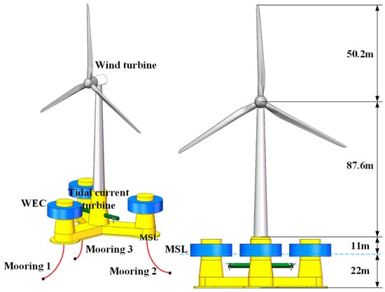
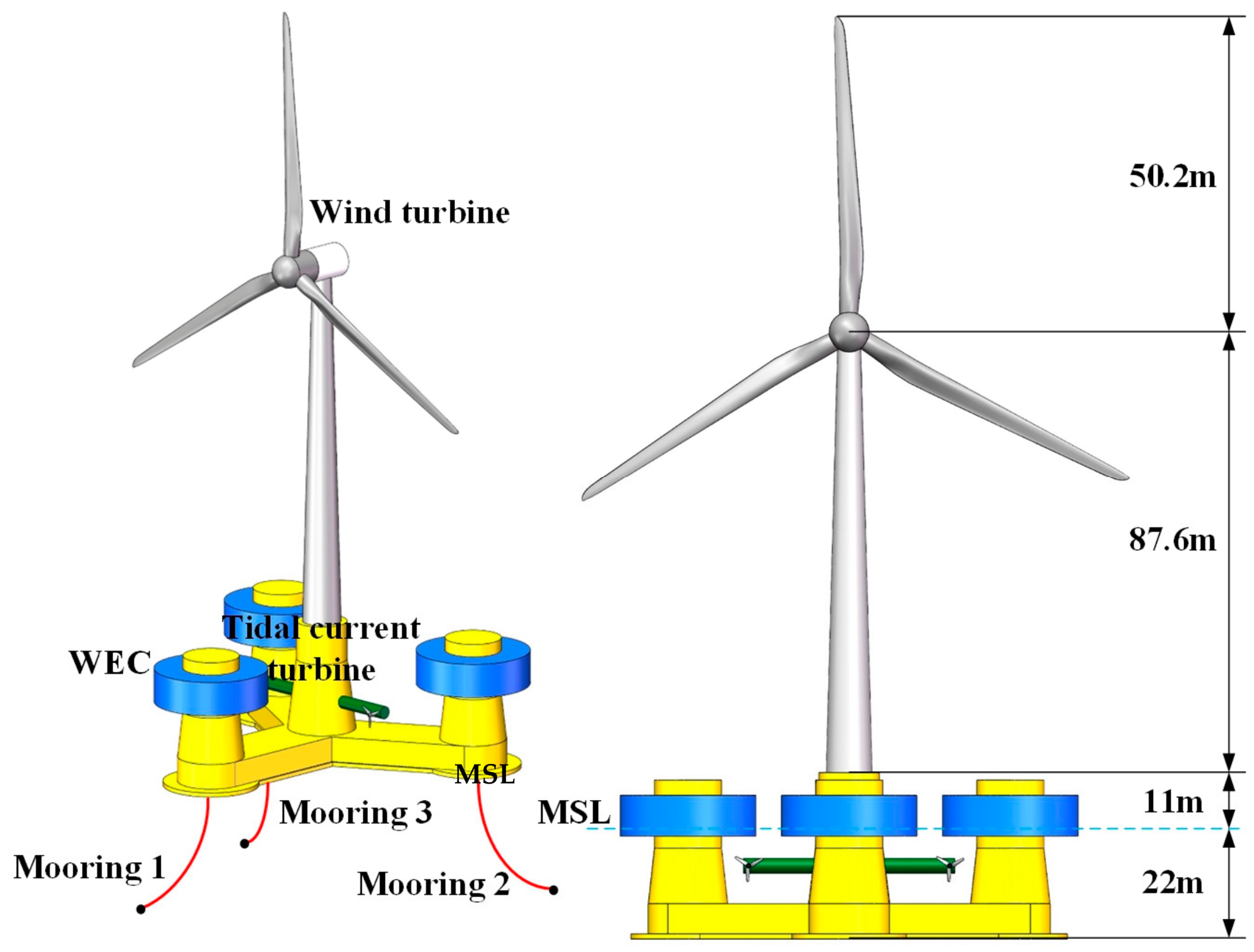
The WWT energy system is mainly composed of a wind turbine, WECs, tidal current turbines and a semi-submersible platform. The wind turbine uses the NREL 5MW wind turbine model. The tidal current turbines are three-bladed horizontal-axis turbines. The main configuration of the WWT energy system is shown in Figure 1.
Figure 1.
Configuration of WWT energy system.
The platform is a semi-submersible platform, consisting of a central column and three outer columns in a symmetrical structure. The main properties of the platform are shown in Table 1.
Table 1.
Main properties of the platform.
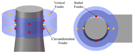
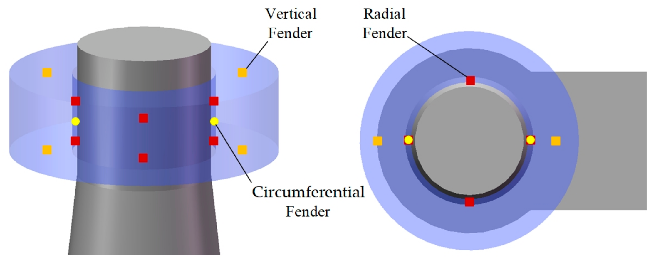
To enhance power generation efficiency and improve platform stability, WECs are installed to capture and convert wave energy. To increase the restoring moment for the platform’s pitch and roll movements, WECs are installed on three outer columns. Each WEC is constrained to move only in the vertical direction relative to its supporting column. In the numerical model, the WEC motions are controlled by introducing fender elements. As illustrated in Figure 2, radial and circumferential fenders are used to represent the pulley–rail connection between each WEC and its supporting column. Large stiffness coefficients are assigned to these fenders to restrain the radial and circumferential relative motions. A vertical fender is used to represent the PTO system, with a stiffness coefficient of 5000 N/m and a damping coefficient of 800 kN·s/m.
Figure 2.
Setting of the fenders in the numerical model.
In addition, two tidal energy turbines are symmetrically installed on both sides of the central column, with their rotor planes remaining parallel with the plane of the wind turbine. Owing to their relatively small size compared with the overall platform, the tidal-turbine thrust loads are not considered in the present numerical model when evaluating the global motion responses of the WWT energy system.
In order to accurately calculate the responses of the WWT energy system under the load of wind, waves and currents, this study adopts a coupling calculation framework that combines FAST (version 7.02) and AQWA (version 2020 R1) [26]. The dynamic behavior of the wind turbine is calculated through FAST, while the hydrodynamic response of the floating platform is computed through AQWA. The full coupling of the calculation data for the two parts is achieved through the built-in DLL file of AQWA. The influence of aerodynamic servo elastic effects and hydrodynamic effects on the WWT energy system is comprehensively considered.
The environmental conditions adopted in the simulations are listed in Table 2. In the simulation, the water depth at the deployment location of the WWT energy system is set to 200 m, and the water area is defined as 600 m × 600 m. The wave behavior is described using the linear Airy wave theory. The tidal current velocity is set to vary with depth from 0.5 m/s to 1 m/s to reflect the actual loading conditions under combined wave–current effects. The wind field is established in accordance with IEC 61400-1. The IEC Kaimal turbulence model is adopted to describe the random fluctuations in offshore boundary-layer wind speed. A power-law wind profile is used to describe the vertical variation in wind speed, with a reference height of 90 m and a reference mean wind speed of 11.4 m/s. The wind, wave, and current are aligned and directed normal to the rotor planes of the tidal turbines and wind turbine. The frequency range for the frequency-domain analysis is set from 0.001 Hz to 0.43 Hz, with a step size of 0.024 Hz, covering the main wave energy frequency band. The total duration for the time-domain analysis is 4000 s, with a timestep size of 0.01 s, to ensure the numerical stability and temporal resolution of the results.
Table 2.
Settings of simulation condition.
The floating platform is fixed to the seabed using a mooring system. Each mooring line is modeled in AQWA using a fixed-point-to-structure connection. The unstretched length of each mooring line is 370 m, with a mass per unit length of 375.4 kg/m, an equivalent cross-sectional area of 0.01474 m2, and an axial stiffness of EA = 8.40 × 10⁸ N. The axial elastic behavior of the mooring cable is assumed to be linear. Based on the above settings, the initial mooring-line tension at the anchor is calculated to be 211 kN.
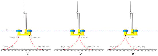
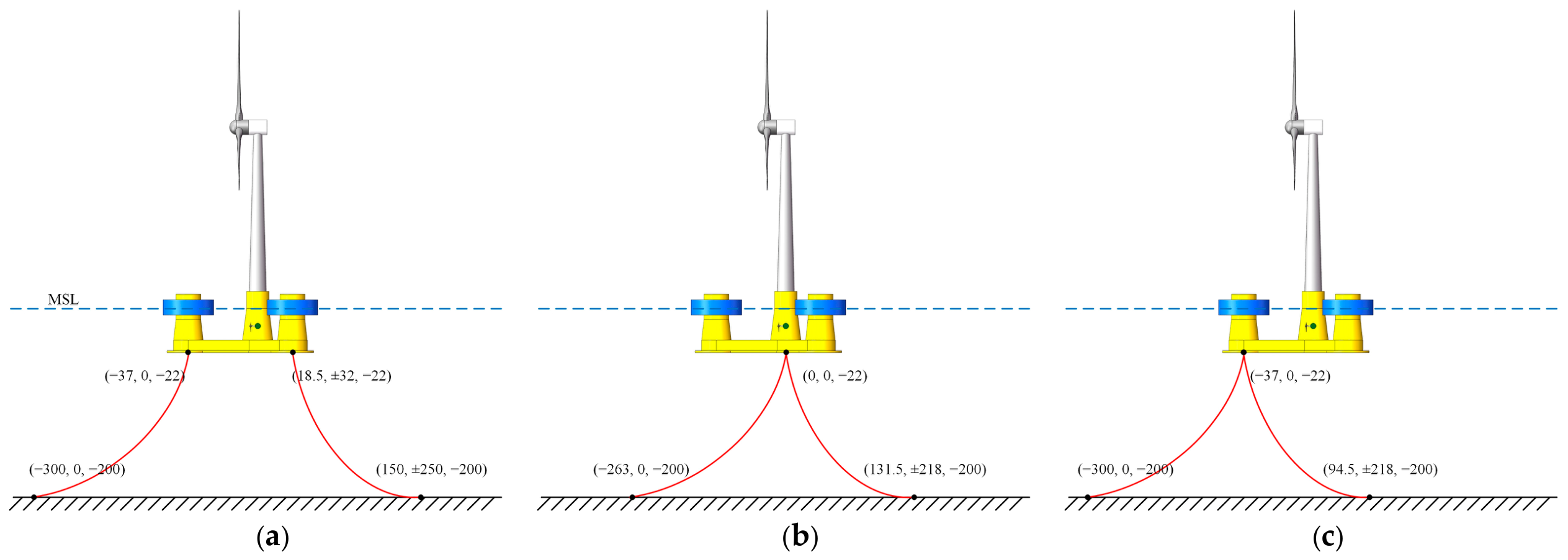
In order to study the influence of mooring systems on the performance of the WWT energy system, this work construct three different mooring systems. Figure 3 presents schematic diagrams of the three different mooring systems. The difference among the three configurations lies in the locations of the connections between the mooring lines and the bottom of the floating platform. To maintain an identical mooring-line length for all configurations, the locations of the corresponding seabed anchor points are adjusted accordingly.
Figure 3.
Schematic diagrams of WWT energy system with different mooring systems. (a) Spread mooring system; (b) central SPM system; (c) forward SPM system.
3.2. Validation
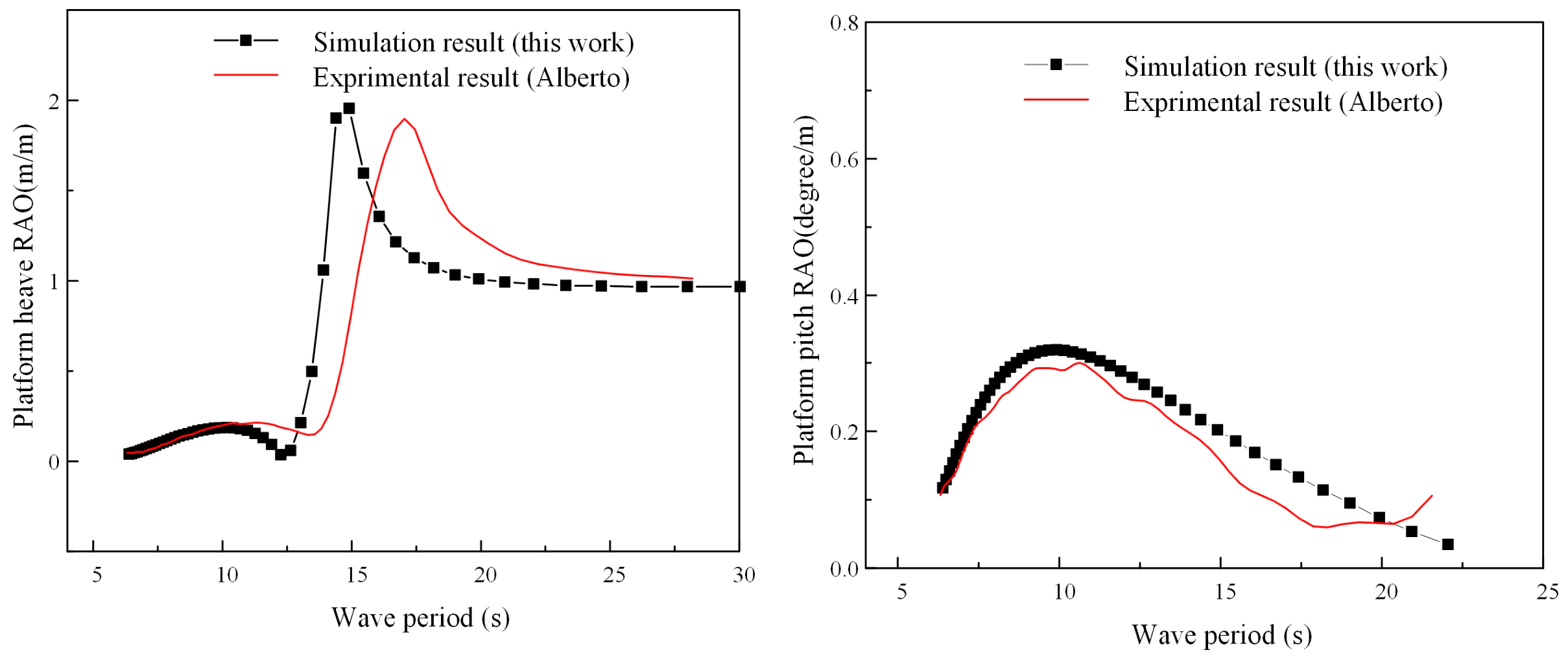
To verify the accuracy of the numerical method used in this work, the floating platform reported in Reference [27] is first simulated. Figure 4 compares the numerical heave and pitch responses with the experimental results reported in the literature for the same platform. The numerical results agree reasonably well with the experimental measurements, supporting the accuracy of the numerical method.
Figure 4.
Comparation between the numerical heave and pitch responses and the experimental results.
Mesh and timestep independence validations are then conducted for the numerical model used in the present work. Table 3 presents the platform heave responses obtained using coarse, medium, and fine meshes. The results obtained with the medium and fine meshes are nearly identical. Therefore, the medium mesh is selected for the subsequent simulations.
Table 3.
Platform heave responses under different meshes.
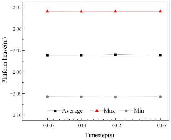
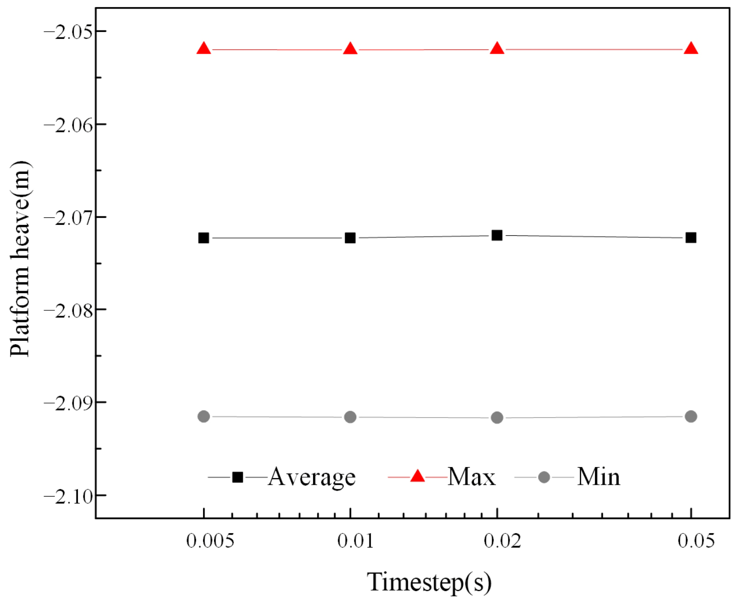
Figure 5 presents the platform heave responses calculated using different timesteps. The results show little variation over the investigated timestep range. Therefore, a timestep of 0.01 s is adopted for the subsequent simulations.
Figure 5.
Average maximum and minimum platform heave under different timesteps.
4. Results and Discussion
4.1. Added Mass
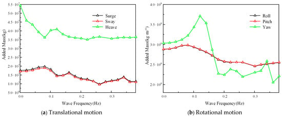
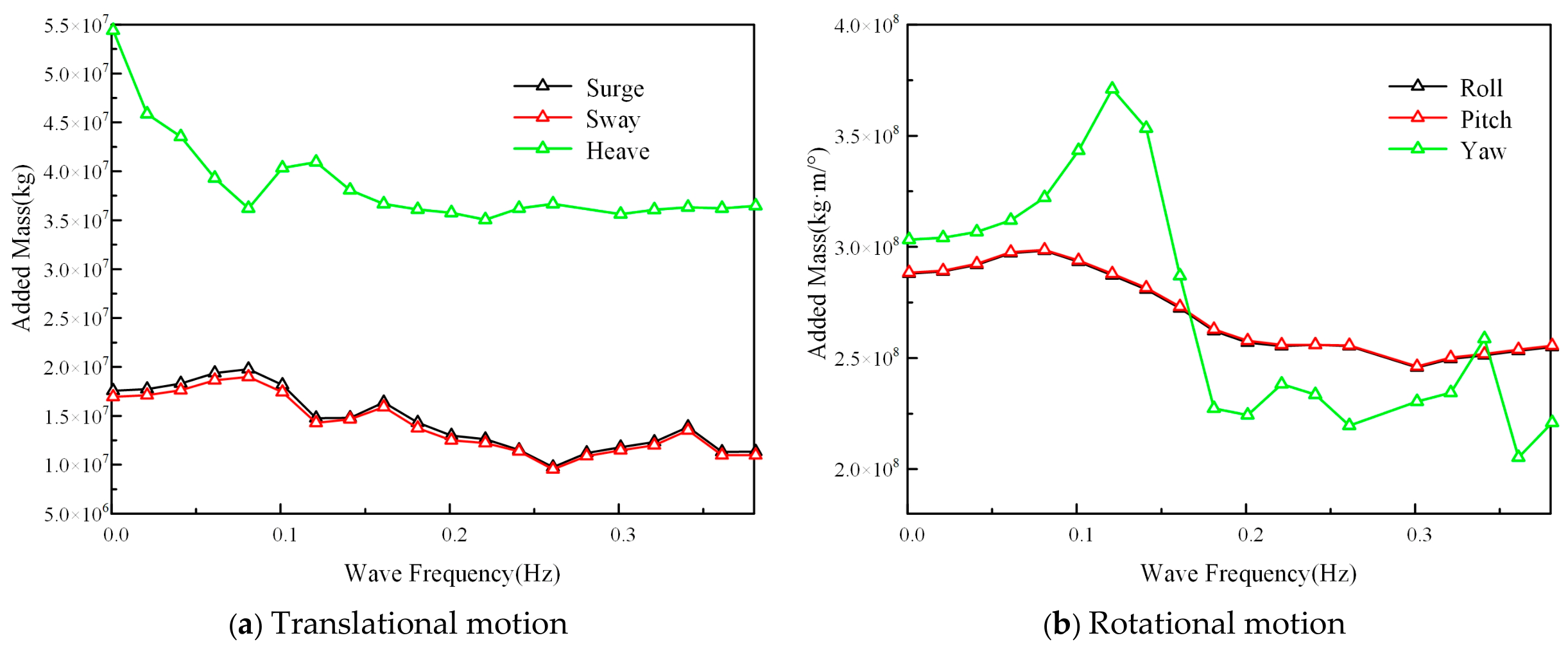
Figure 6 shows the variation in the added mass of the offshore platform with the wave frequency in six motion directions. As can be seen from the figure, in the direction of translational motion, the added mass generally shows a decreasing trend as the wave frequency increases. This indicates that the horizontal movement of the platform is mainly influenced by large-scale circulation and radiation wave effects. Under the action of low-frequency waves, the larger range of fluid participation in the movement results in a higher additional mass. As the frequency increases, the range of fluid disturbance decreases, and the additional inertial effect gradually decreases. Due to the symmetry of the platform, the variations in added mass in the surge and sway directions are basically the same. In contrast, the added mass in the heave direction is significantly higher than that in the horizontal motion direction. This is mainly because the vertical movement of the platform requires pushing a larger volume of fluid to generate motions, making the vertical additional inertial effect more pronounced.
Figure 6.
Variation in the added mass with the wave frequency in six motion directions.
In the direction of rotational motion, the trends of mass changes in the roll and pitch directions are relatively similar. They generally show a decreasing trend as the frequency increases. In contrast, the mass changes in the yaw direction vary most significantly with frequency. In the low-frequency range, the added mass in yaw direction increases rapidly with the increase in frequency, reaching a peak around 0.12 Hz, and then rapidly decreases. This strong frequency dependence mainly stems from the complex flow characteristics when the platform rotates around the vertical axis. When the wave frequency approaches the frequency related to the platform’s rotational motion, the surrounding fluid undergoes strong synchronous movement, thereby resulting in a larger additional rotational inertia.
4.2. Response Amplitude Operator
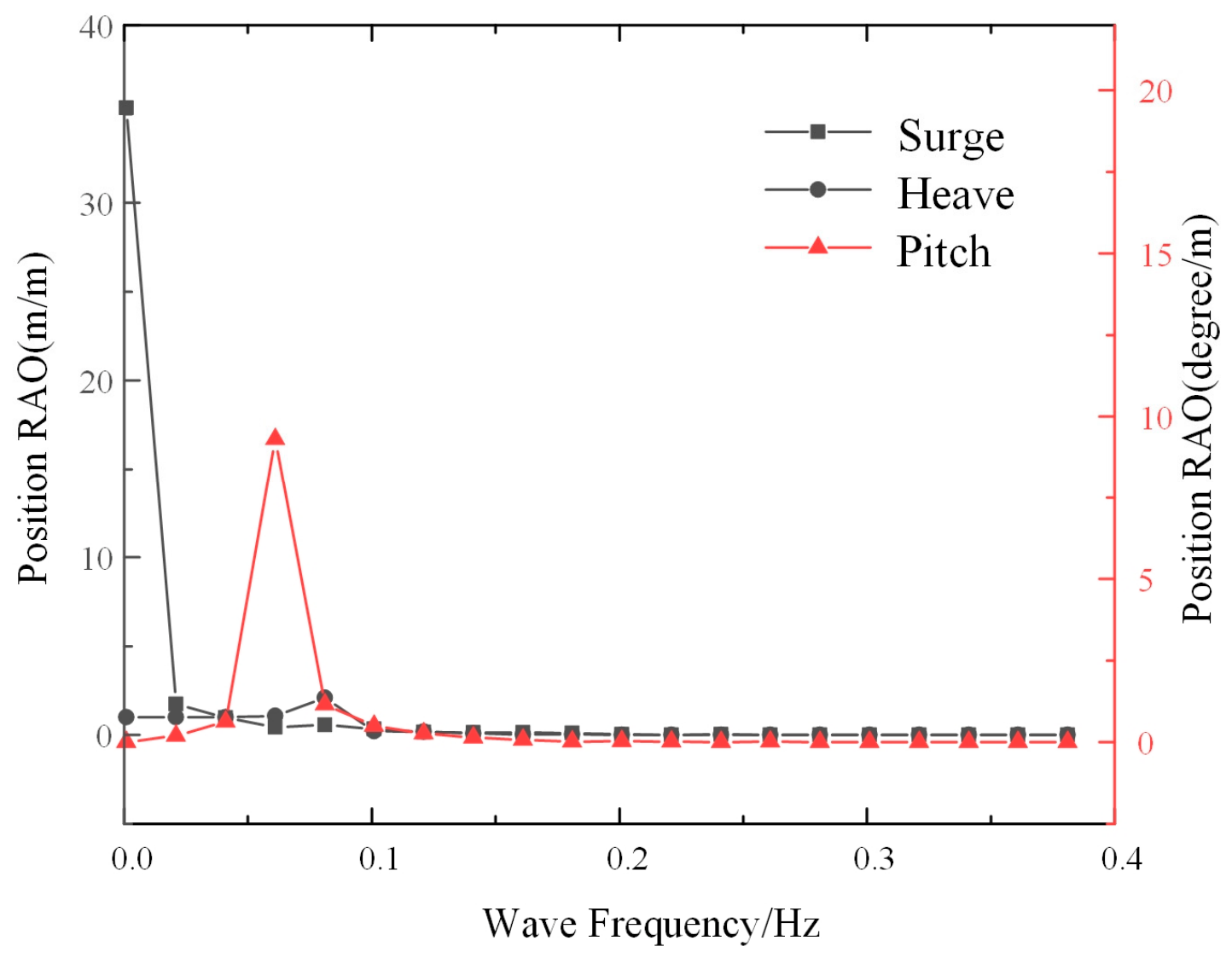
Due to the symmetry of the platform, its motion responses in the sway, roll and yaw directions are relatively small. Therefore, this work mainly focuses on the motion characteristics in the surge, heave and pitch directions. Figure 7 shows the Response Amplitude Operator (RAO) of the platform with the spread mooring system in the three motion directions of surge, heave and pitch. It can be observed that in the surge direction, RAO exhibits the most significant response characteristics in the low-frequency range. This is mainly related to the horizontal drift motion characteristics of the platform. In the heave direction, the RAO reaches a peak around 0.08–0.09 Hz. The peak frequency corresponds to the natural frequency of the platform’s vertical motion. In the pitch direction, a relatively high peak appears around 0.06–0.07 Hz in RAO. This indicates that the pitch motion of the platform has a strong frequency-selective response. When the incident wave frequency is close to the inherent pitch frequency of the platform, a resonance occurs between the wave excitation moment and the restoring moment of the platform, significantly enhancing the pitch response.
Figure 7.
RAO of platform with spread mooring system in motion direction of surge, heave and pitch.
4.3. Dynamic Response
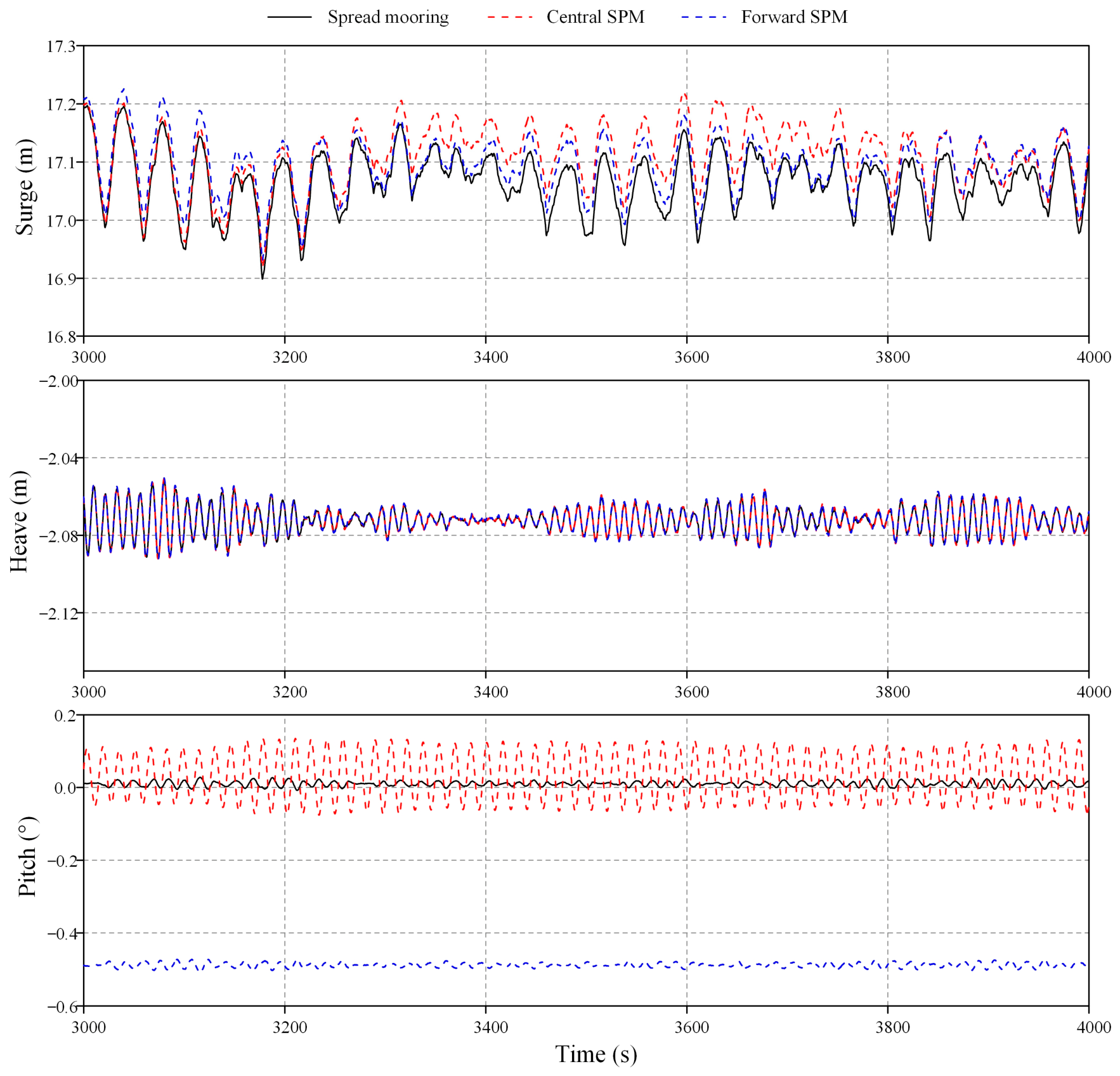
Figure 8 presents the time-domain motion responses of the WWT energy systems under three different mooring systems. In addition, Table 4 presents the mean motion offsets and oscillation amplitudes for the different mooring configurations over the period from 3000 s to 4000 s. All displacement data are referenced to the initial position of the platform center of gravity. As shown in the figure, the platform motion exhibits a periodic oscillation characteristic under all three mooring systems, but there are differences in the response amplitude and average offset. The spread mooring system shows the lowest response in surge direction. This indicates that multi-point mooring provides a higher horizontal restoring stiffness through the combination of multiple mooring cables, thereby effectively limiting the surge motion of the platform. In contrast, the surge responses under central SPM and forward SPM are slightly higher. Among them, central SPM shows the largest average offset and oscillation amplitude. This is because SPM reduces the horizontal constraint ability in some directions, making the platform more prone to low-frequency drift movements. For forward SPM, since the mooring point is located at the front end of the platform, there is a considerable distance between the mooring point and the center of the platform. The mooring force can generate a large restoring moment, thereby enhancing the attitude adjustment capability of the platform. Therefore, its surge response is slightly lower than that of central SPM.
Figure 8.
Time-domain motion responses of the WWT energy systems under three different mooring systems.
Table 4.
Mean offsets and oscillation amplitudes of platform motions.
In heave direction, the responses of the three mooring systems are basically the same, all oscillating periodically around an average position of approximately −2.07 m. This indicates that the change in mooring system has a relatively small impact on the heave movement of the platform.
In pitch direction, there are significant differences among various mooring systems. Under the spread mooring system, both the mean pitch offset and the oscillation amplitude remain small, indicating that the multi-point mooring effectively limits the platform’s attitude changes through the symmetrical arrangement of mooring lines. For the central SPM system, the mean pitch offset is also small; however, the pitch oscillation amplitude is the largest among the three configurations. This is because the mooring connection point is located close to the platform center, resulting in a relatively short mooring-force lever arm and limited pitch-restoring capability under wave excitation. In contrast, the forward SPM system exhibits a relatively large mean pitch offset but a small oscillation amplitude. The forward position of the mooring connection point generates a steady pitch moment under the mean mooring tension, thereby shifting the platform to a new equilibrium attitude. Meanwhile, the increased lever arm provides a larger restoring moment against dynamic pitch variations, which effectively suppresses pitch oscillations around this offset equilibrium position.
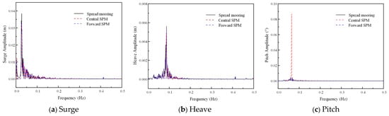
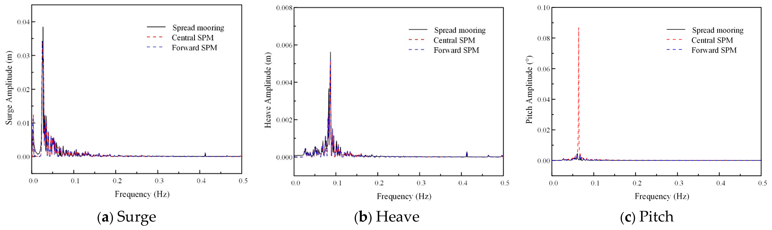
The frequency-domain motion responses are obtained by performing FFT transformations on the final 500 s of the platform motion response in different motion directions, with a sampling interval of 0.01 s. Before the FFT, the mean value of each time history is removed, and a single-sided amplitude spectrum is used to obtain the frequency-domain distributions of the platform motions. Figure 9 shows the frequency-domain distribution characteristics of the platform’s motion response under different mooring systems. It can be observed that the motion frequencies of the platform are mainly concentrated in the low-frequency range under the three mooring systems. The peak frequency in the surge direction is around 0.03 Hz, the peak frequency in the heave direction is around 0.08–0.09 Hz, and the peak frequency in the pitch direction is around 0.06–0.07 Hz. In addition, relatively small high-frequency peaks around 0.4–0.45 Hz are observed in the surge and heave directions, corresponding to the wave excitation frequency. However, their amplitudes are much smaller than those of the low-frequency peaks. This indicates that the platform response is mainly governed by the low-frequency drift motion induced by the mooring system, while the influence of the first-order wave excitation is relatively small. Among them, the pitch direction movement shows the most significant sensitivity to the mooring system. From the spectral results, it can be seen that the central SPM has a much higher amplitude of movement at the peak frequency than the other two mooring systems. This is consistent with the analysis results of the above time-domain data.
Figure 9.
Frequency-domain motion responses of the WWT energy systems under three different mooring systems.
4.4. Mooring Tension
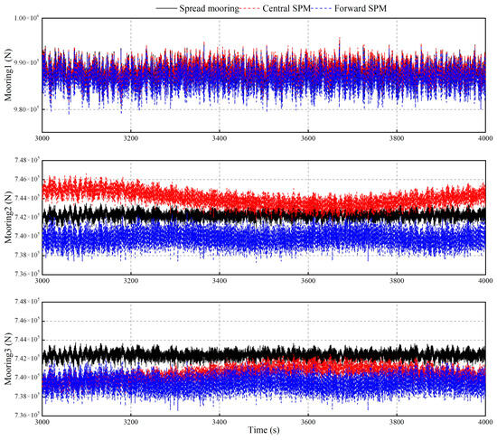
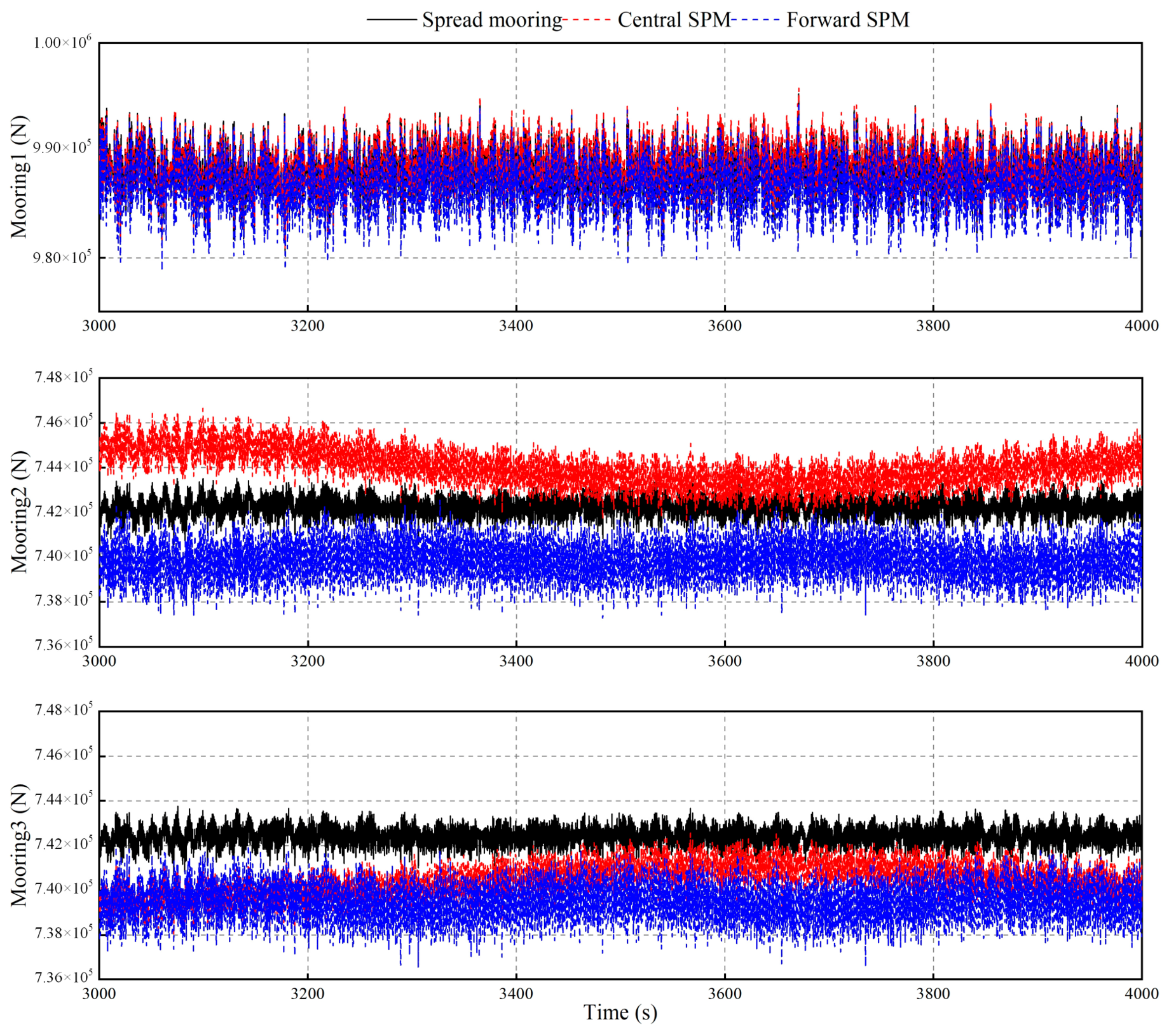
Figure 10 illustrates the variation in the tension in the mooring lines over time under the three mooring systems. In addition, Table 5 presents the mean values and oscillation amplitudes of the tensions in the three mooring lines over the final 1000 s.
Figure 10.
Time history of tensions in mooring cables under three different mooring systems.
Table 5.
Mean values and oscillation amplitudes of mooring-line tensions.
The average tension of Mooring1 is relatively close under the three mooring systems, and the amplitude of tension fluctuation is relatively large. This is because Mooring1 is located at the front end of the platform and directly bears the main restoring effect caused by the drift surge motion of the platform, so its tension changes are more significant. For Mooring2 and Mooring3, different mooring systems show more obvious differences. In the spread mooring condition, the tensions of the two rear mooring cables remain basically at a similar level, indicating that the multi-point mooring system achieves a relatively uniform load distribution through the symmetrical arrangement of the mooring cables. The tension of Mooring2 and Mooring3 of central SPM is greater than that of forward SPM. This is because the mooring point of central SPM is located near the middle of the platform, resulting in a reduction in the restoring moment provided by the mooring system. To balance the moment generated by the environmental load, the two rear mooring cables need to bear higher tension.
5. Conclusions
In this work, the effects of different mooring configurations on the hydrodynamic characteristics and dynamic responses of the WWT energy system are investigated. Three mooring systems, namely, spread mooring, central SPM, and forward SPM, are established and compared through numerical simulation using a coupling calculation framework that combines FAST and AQWA.
The results demonstrate that the mooring configuration has a significant influence on the motion behavior of the WWT energy system. Under the wave-height condition adopted in the present simulations, the spread mooring system provides stronger horizontal restoring capability due to the distributed arrangement of multiple mooring lines, resulting in relatively smaller surge responses and a more balanced load distribution among mooring lines. In contrast, the SPM systems allow the platform to rotate freely around the mooring point, while their dynamic performance is strongly affected by the position of the mooring point. Compared with central SPM, forward SPM increases the distance between the mooring force application point and the platform center of gravity, leading to a larger restoring moment and improved stability. As a result, the pitch response and low-frequency motion characteristics are effectively reduced.
The frequency-domain analysis further reveals that the influence of mooring configurations varies among different motion direction. Surge motion is mainly dominated by low-frequency drift effects, whereas the heave response is less sensitive to the mooring arrangement. The pitch response exhibits a stronger dependence on the mooring layout, and the shift in the SPM position significantly modifies the corresponding response characteristics.
Overall, the results indicate that the SPM connection-point position is a key parameter affecting the motion performance and mooring behavior of floating platforms. Compared with the central SPM configuration, forward SPM provides improved motion control capability by reducing the pitch oscillation amplitude. However, the present study considers only one environmental loading condition and neglects tidal-turbine thrust. These limitations restrict the generalization of the results to other operating conditions. Future work will examine a wider range of wind, wave, and current conditions, and incorporate tidal-turbine thrust to assess its effects on platform motions and mooring loads. Further investigation of the SPM connection-point position will support the optimization of mooring arrangements for WWT energy systems.
Author Contributions
Conceptualization, M.Y. and H.F.; Methodology, M.Y.; Software, Z.C.; Validation, Y.L., Z.C., C.W. and W.W.; Formal Analysis, M.Y., Y.L. and C.W.; Investigation, Z.C. and W.W.; Resources, Y.L.; Data Curation, C.W. and W.W.; Writing—Original Draft, M.Y.; Writing—Review and Editing, Y.L. and H.F.; Supervision, H.F. All authors have read and agreed to the published version of the manuscript.
Funding
This research received no external funding.
Institutional Review Board Statement
Not applicable.
Informed Consent Statement
Not applicable.
Data Availability Statement
The original contributions presented in this study are included in the article. Further inquiries can be directed to the corresponding author.
Conflicts of Interest
Authors Yan Liu, Cui Wang, and Wankun Wang were employed by the company China Datang Technology Innovation Co., Ltd. The remaining authors declare that the research was conducted in the absence of any commercial or financial relationships that could be construed as a potential conflict of interest.
References
- Muliawan, M.J.; Karimirad, M.; Moan, T. Dynamic response and power performance of a combined Spar-type floating wind turbine and coaxial floating wave energy converter. Renew. Energy 2013, 50, 47–57. [Google Scholar] [CrossRef] [Scilit]
- Wan, L.; Moan, T.; Gao, Z.; Shi, W. A review on the technical development of combined wind and wave energy conversion systems. Energy 2024, 294, 130885. [Google Scholar] [CrossRef] [Scilit]
- Ghafari, H.R.; Ghassemi, H.; He, G. Numerical study of the Wavestar wave energy converter with multi-point-absorber around DeepCwind semisubmersible floating platform. Ocean Eng. 2021, 232, 109177. [Google Scholar] [CrossRef] [Scilit]
- Zhou, B.; Hu, J.; Jin, P.; Sun, K.; Li, Y.; Ning, D. Power performance and motion response of a floating wind platform and multiple heaving wave energy converters hybrid system. Energy 2023, 265, 126314. [Google Scholar] [CrossRef] [Scilit]
- Bayat, S.; Zuo, J.; Sun, J. Modeling and dynamic simulation of a hybrid floating wind–wave platform with integrated flap-type wave energy converters. Ocean Eng. 2026, 346, 123684. [Google Scholar] [CrossRef] [Scilit]
- Li, L.; Gao, Y.; Yuan, Z.; Day, S.; Hu, Z. Dynamic response and power production of a floating integrated wind, wave and tidal energy system. Renew. Energy 2018, 116, 412–422. [Google Scholar] [CrossRef] [Scilit]
- Yi, Y.; Sun, K.; Liu, Y.; Zhang, J.; Zhang, H.; Zhu, R.; Yao, H.D. Coupled numerical framework for wind-wave-to-wire energy conversion in floating hybrid wind-wave systems. Appl. Energy 2026, 403, 127106. [Google Scholar] [CrossRef] [Scilit]
- Amouzadrad, P.; Mohapatra, S.C.; Guedes Soares, C. Numerical model for the hydroelastic response of a moored articulated floating platform with a flap-type wave energy converter. J. Ocean Eng. Mar. Energy 2026, 12, 697–715. [Google Scholar] [CrossRef] [Scilit]
- Striani, R.; Jiang, H.; Biroli, M.V.; Shao, Y.; Wang, S. Review of Floating Offshore Wind Turbines with Shared Mooring Systems. J. Mar. Sci. Eng. 2025, 13, 2341. [Google Scholar] [CrossRef] [Scilit]
- Hall, M.; Buckham, B.; Crawford, C. Evaluating the importance of mooring line model fidelity in floating offshore wind turbine simulations. Wind Energy 2014, 17, 1835–1853. [Google Scholar] [CrossRef] [Scilit]
- Mohapatra, S.C.; Amouzadrad, P.; Bispo, I.B.D.S.; Guedes Soares, C. Hydrodynamic response to current and wind on a large floating interconnected structure. J. Mar. Sci. Eng. 2025, 13, 63. [Google Scholar] [CrossRef] [Scilit]
- Iijima, K.; Kawai, M.; Nihei, Y.; Murai, M.; Ikoma, T. Conceptual Design of a Single-Point-Moored Fowt and Tank Test for Its Motion Characteristics. In Proceedings of the ASME 32nd International Conference on Ocean, Offshore and Arctic Engineering, Nantes, France, 9–14 June 2013; American Society of Mechanical Engineers: New York, NY, USA, 2013; Volume 8. [Google Scholar]
- Nihei, Y.; Matsuda, Y.; Kitamura, S.; Takaiwa, K.; Kanda, N. Research and development about the mechanisms of a single point mooring system for offshore wind turbines. Ocean Eng. 2018, 147, 431–446. [Google Scholar] [CrossRef] [Scilit]
- Chen, M.; Jiang, J.; Zhang, W.; Li, C.B.; Zhou, H.; Jiang, Y.; Sun, X. Study on Mooring Design of 15 MW Floating Wind Turbines in South China Sea. J. Mar. Sci. Eng. 2024, 12, 33. [Google Scholar] [CrossRef] [Scilit]
- Liu, B.; Yu, J. Effect of Mooring Parameters on Dynamic Responses of a Semi-Submersible Floating Offshore Wind Turbine. Sustainability 2022, 14, 14012. [Google Scholar] [CrossRef] [Scilit]
- Trubat, P.; Molins, C.; Gironella, X. Wave hydrodynamic forces over mooring lines on floating offshore wind turbines. Ocean Eng. 2020, 195, 106730. [Google Scholar] [CrossRef] [Scilit]
- Chen, J.; Li, Z.; Yin, Z.; Fan, S.; Deng, Y. Experimental research on wind tracking performance of a single-point moored floating offshore wind turbine. J. Renew. Sustain. Energy 2025, 17, 013305. [Google Scholar] [CrossRef] [Scilit]
- Chen, J.; Ma, Y.; Guo, Z.; Zha, R. Performance and optimization of wind tracking of a single-point moored floating offshore wind turbine. Ocean Eng. 2025, 329, 121139. [Google Scholar] [CrossRef] [Scilit]
- Sandua-Fernández, I.; Martín-San-Román, R.; Eguinoa, I.; Cascales-Gómez, A.; Iribas-Latour, M. About control of bi-wind turbine single-point-moored floating offshore wind turbines. J. Phys. Conf. Ser. 2024, 2767, 032031. [Google Scholar] [CrossRef] [Scilit]
- Zhang, H.; Liu, X.; Cao, X.; Zhang, N.; Law, A.W.K. Dynamic response and power performance of a novel wind-wave-tidal energy system with single-point mooring integration. Energy 2025, 325, 136114. [Google Scholar] [CrossRef] [Scilit]
- Ivanov, G.; Wu, Y.; Ma, K.T. Optimized mooring solutions for floating offshore wind turbines in harsh environments. Ocean Eng. 2025, 340, 122289. [Google Scholar] [CrossRef] [Scilit]
- ANSYS Inc. Ansys Aqwa Theory Manual; Release 2020 R1; ANSYS Inc.: Canonsburg, PA, USA, 2020. [Google Scholar]
- Newman, J.N. Second-order, slowly-varying forces on vessels in irregular waves. In Proceedings of the International Symposium on the Dynamics of Marine Vehicles and Structures in Waves, London, UK, 1–5 April 1974; pp. 182–186. [Google Scholar]
- Burton, T.; Jenkins, N.; Sharpe, D.; Bossanyi, E. Wind Energy Handbook, 2nd ed.; John Wiley & Sons: Chichester, UK, 2011. [Google Scholar]
- Hall, M. Generalized quasi-static mooring system modeling with analytic Jacobians. Energies 2024, 17, 3155. [Google Scholar] [CrossRef] [Scilit]
- Yang, Y.; Bashir, M.; Michailides, C.; Li, C.; Wang, J. Development and application of an aero-hydro-servo-elastic coupling framework for analysis of floating offshore wind turbines. Renew. Energy 2020, 161, 606–625. [Google Scholar] [CrossRef] [Scilit]
- Amaral, G.A.; Mello, P.C.; do Carmo, L.H.; Alberto, I.F.; Malta, E.B.; Simos, A.N.; Franzini, G.R.; Suzuki, H.; Gonçalves, R.T. Seakeeping Tests of a FOWT in Wind and Waves: An Analysis of Dynamic Coupling Effects and Their Impact on the Predictions of Pitch Motion Response. J. Mar. Sci. Eng. 2021, 9, 179. [Google Scholar] [CrossRef] [Scilit]

Disclaimer/Publisher’s Note: The statements, opinions and data contained in all publications are solely those of the individual author(s) and contributor(s) and not of MDPI and/or the editor(s). MDPI and/or the editor(s) disclaim responsibility for any injury to people or property resulting from any ideas, methods, instructions or products referred to in the content. |
© 2026 by the authors. Licensee MDPI, Basel, Switzerland. This article is an open access article distributed under the terms and conditions of the Creative Commons Attribution (CC BY) license.