


Abstract
To address the dual challenges of improving precast cable trench joint performance and promoting solid waste recycling for carbon neutrality, this study developed a jute fiber-reinforced recycled aggregate concrete (JFRAC) and established a complete technical chain via experiments and numerical simulations. Compressive strength tests were conducted on JFRAC with varying jute fiber volume content and recycled coarse aggregate (RCA) replacement ratio to obtain their influence on the stress–strain relationship. A modified Concrete Damaged Plasticity (CDP) model was proposed by introducing correction coefficients for compressive strength and elastic modulus, achieving over 95% agreement with experimental data. Finite element simulations of cable trench joints showed that JFRAC outperforms C30 concrete, with the same compressive strength, in ultimate bearing capacity (↑4.17%), peak displacement (↑18.78%), and ductility (↑14.66%). JFRAC provides substantial environmental and economic advantages by reducing carbon emissions by 2.29% and saving costs of CNY 62.43 per meter of precast cable trench. Parametric studies indicated bolt grade and number are the primary performance influencers. Bolt grade’s impact diminishes as it increases from 8.8 to 10.9, while bolt number linearly enhances load-bearing capacity. This study provides a feasible path for JFRAC to replace conventional concrete in cable trenches, realizing both economic and environmental benefits.
1. Introduction
Cable trenches are widely used as precast concrete components in power systems, where the load-bearing capacity of their connection joints often constitutes a structural weak point. Especially when uneven settlement of the foundation occurs, cable trench joints may be subjected to loads far exceeding their design capacity, which may nngg’slead to issues, such as misalignment, structural cracking, and even fatigue failure of the joints [1]. The flexural performance of precast cable trench joints is influenced not only by connecting bolts but also significantly by the behavior of the concrete [2]. With the rapid development of urban construction in China, large volumes of old buildings have been demolished, generating a large amount of waste concrete. Therefore, improving the load-bearing capacity of precast cable trench joints and utilizing the construction waste simultaneously is a valuable research topic.
Concrete is a commonly used building material in precast cable trench joints. On the one hand, to minimize environmental pollution as much as possible, many scholars have proposed incorporating recycled fibers, such as glass fiber, steel fiber, plastic fiber, and plant fiber [3,4,5,6], to ensure the mechanical properties of concrete meet engineering requirements. These studies indicate that various recycled fibers improve the compressive and flexural strength of concrete to varying degrees, among which jute fiber is widely used by researchers due to its advantages of low cost and easy availability of raw materials [7,8,9,10,11]. On the other hand, rapid urbanization and natural disasters (e.g., earthquakes) have generated massive construction waste, particularly waste concrete—its disposal pollutes the environment and wastes resources. Scholars have proposed crushing waste concrete into recycled aggregates to replace natural coarse aggregates [12,13,14], but recycled aggregates’ inherent defects reduce concrete mechanical properties [15,16,17]. Since recycled fibers significantly improve concrete durability and can compensate for the deterioration in mechanical properties caused by the incorporation of recycled aggregate, some scholars are committed to simultaneously using RCA made from waste concrete and recycled fibers to prepare fiber-reinforced recycled concrete [18,19,20]. This aims to achieve the rational resource utilization of solid waste and produce concrete with enhanced mechanical properties to meet engineering needs in different scenarios.
Previous studies have explored the use of recycled fibers or waste coarse aggregates to prepare fiber-reinforced recycled concrete [21,22,23,24,25] to fully utilize solid waste resources and improve concrete performance, which has served as an important foundation for ensuing research on recycled aggregate concrete. Some scholars have explored the effects of fiber content and recycled aggregate mix ratio on the macro- and micromechanical properties of fiber-reinforced recycled concrete. However, there is currently a lack of constitutive models for fiber-reinforced recycled concrete that can simultaneously reflect the influence of both fiber content and RCA replacement rate, and most of the applications of the concrete constitutive model still follow the CDP model. Xu [26] employed the CDP constitutive model to simulate the nonlinear damage behavior of concrete under strong seismic conditions, thereby providing an important foundation for quantitatively assessing the impact of oblique incidence of near-fault seismic waves on the dynamic response of concrete dams. Peter [27] further introduced independent tension and compression damage variables into the original CDP constitutive model, enabling a more realistic simulation of the mechanical behavior of concrete under cyclic tensile and compressive loading. Ding et al. [28] proposed a formulation that simultaneously accounts for the influence of the Lode angle and hydrostatic pressure on the damage evolution process of concrete, which describes the strength and failure surfaces of both ordinary concrete and lightweight aggregate concrete under multi-axial stress states. While current research predominantly applies the fundamental concrete CDP model, the existing constitutive model cannot adequately capture the mechanical effects induced by varying contents of recycled jute fiber and RCA. Consequently, it is imperative to propose a relevant constitutive model that reflects the effects of recycled jute fiber and RCA.
In addition, while most scholars focus on the macro- and micromechanical properties, durability, and constitutive modeling of fiber-reinforced recycled concrete and RCA concrete [29,30,31,32,33], only a few scholars have conducted finite element analysis [34]. Thus, applying the jute fiber and RAC in the concrete of precast cable trench joints and investigating the bearing capacity at their connection joints still requires further exploration. Many scholars have investigated the influence of concrete properties and bolt strength on the mechanical performance of precast cable trench joints through model tests or numerical simulation methods [35,36,37,38,39]. There is an urgent need to conduct research on the bearing capacity of JFRAC precast cable trench joints and their performance improvement compared to plain concrete precast cable trench joints [40,41,42]. Furthermore, the influence of factors such as bolt grade, bolt preload, bolt diameter, and number of bolts on the bearing capacity of JFRAC precast cable trench joints requires further investigation.
This study aims to establish a novel modified CDP model for JFRAC and evaluate its performance in a practical engineering context. The research methodology is as follows: First, JFRAC specimens were prepared using RCA and jute fiber, and their compressive strength was experimentally determined. Subsequently, a modified CDP constitutive model for JFRAC was developed based on the test results to reflect the influences of fiber content and RCA replacement ratio, and its accuracy was verified. Furthermore, finite element models of precast cable trench joints constructed from JFRAC and conventional C30 concrete were established and comparatively analyzed using this constitutive model. Finally, a parametric study was conducted using JFRAC models to analyze the influence of bolt grade, preload, diameter, and number on the performance of the connection node components. This study provides a complete technical chain for sustainable infrastructure applications by developing a targeted modified CDP model, verifying JFRAC’s feasibility in cable trench joints, and clarifying key bolt design parameters.
2. Compressive Strength Test and Constitutive Model
2.1. Compressive Strength Test
2.1.1. Test Materials and Procedure
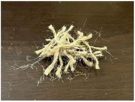
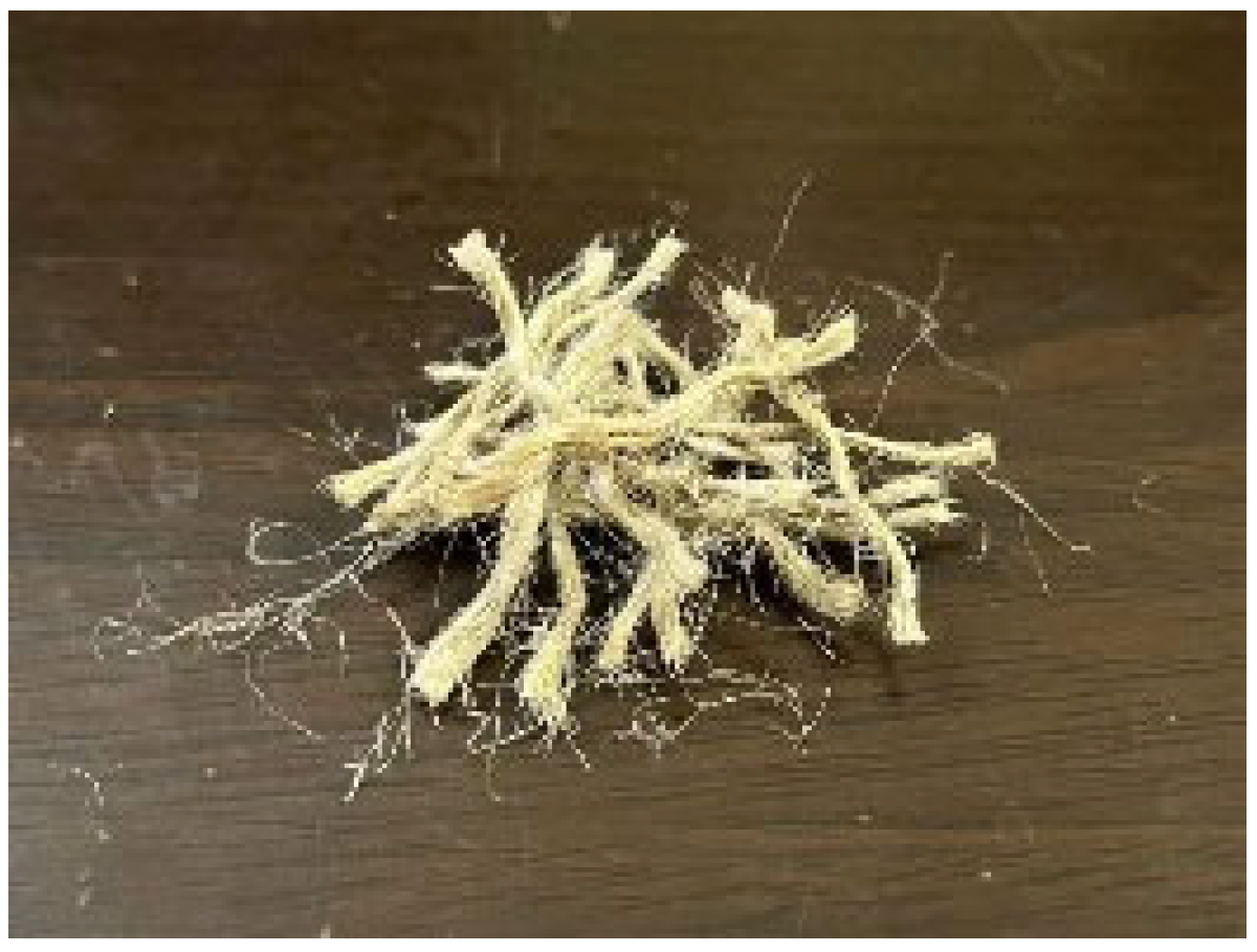
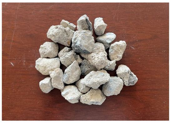
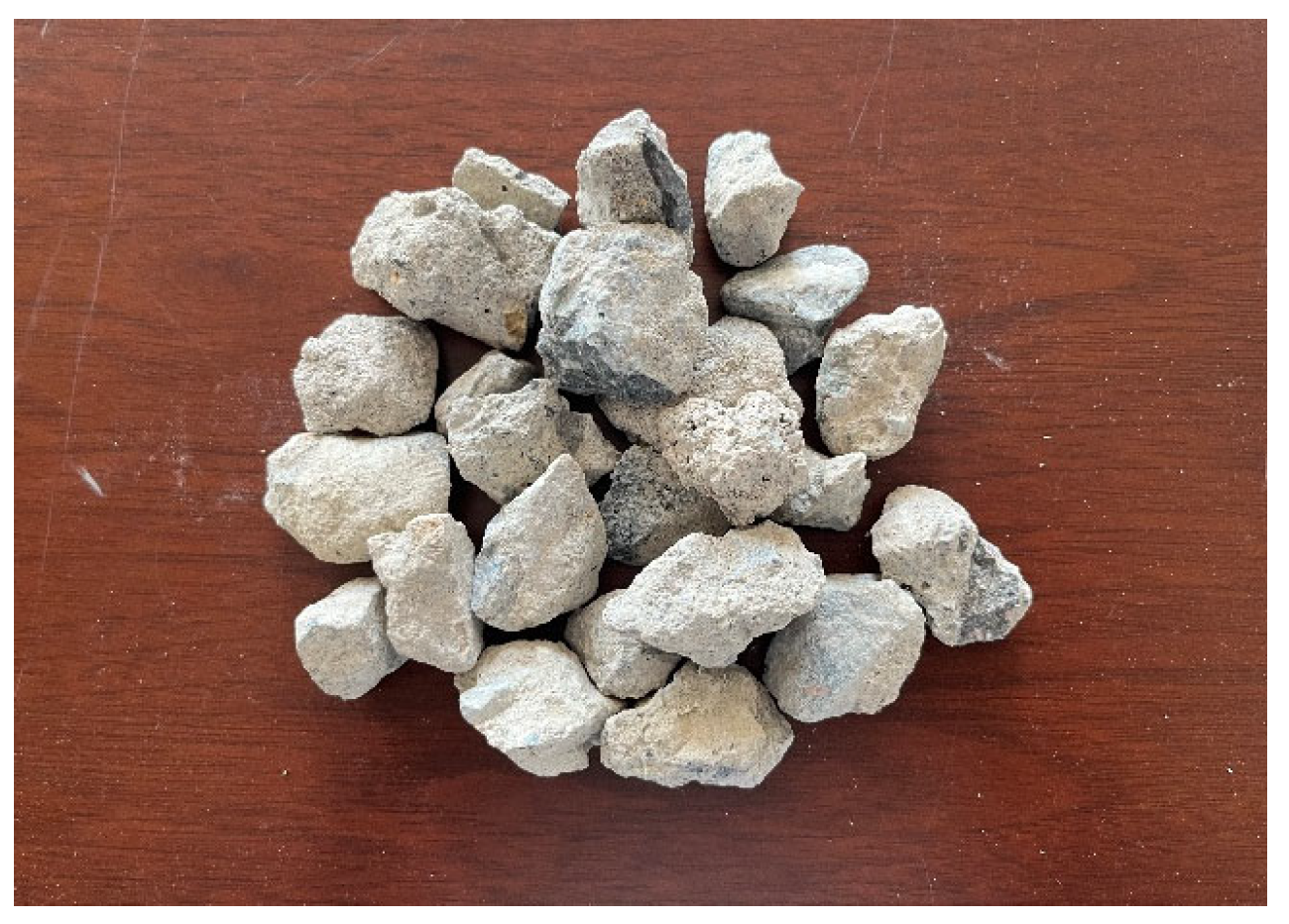
The raw material for the recycled jute fiber was sourced from discarded jute ropes, with a fiber density of 1180 kg/m3, a fiber length of 20–30 mm, and a maximum diameter of 2–4 mm, as shown in Figure 1. The coarse aggregate consisted of continuously graded natural crushed stone and recycled crushed stone with a maximum particle size of 5–30 mm. The recycled aggregate was derived from C30 waste concrete, as shown in Figure 2. The fine aggregate was natural river sand, the cementitious material was Conch brand 32.5 Portland cement, and the mixing water was municipal tap water.
Figure 1.
Recycled jute fiber.
Figure 2.
Recycled coarse aggregate.
Using the RCA replacement rate (0, 50%, 100%) and the recycled jute fiber volume content (0, 0.5%, 1.0%, 1.5%) as variable parameters, seven mix proportions of recycled fiber reinforced recycled aggregate concrete were designed. The nominal water–cement ratio was 0.36, and additional water was added accordingly, considering the water absorption of the RCA. Details are shown in Table 1. The first group was the control group, which was C30 concrete without RCA and without recycled jute fiber.
Table 1.
Material proportions (kg/m3).
Referring to ASTM C39/C39M [43], three standard cylindrical parallel specimens with a diameter of 150 mm and a height of 300 mm were designed and fabricated for each mix proportion. The specimen preparation process was as follows: first, the coarse and fine aggregates were dry-mixed uniformly. Subsequently, the recycled fiber was evenly sprinkled in four separate additions, with each addition followed by 1 min of mixing until the fibers were completely dispersed and free of clumping. Cement was then added and dry-mixed for 1 min. Finally, water was added for wet mixing until the mixture was uniform and without bleeding, to ensure the uniform distribution of the recycled jute fiber in the concrete. The mixture was then poured into molds and compacted by vibration. After 24 h in the laboratory environment, the molds were removed, and the specimens were transferred to a standard curing room for 28 days of curing.
After specimen preparation, with reference to ASTM C39/C39M [43], tests were conducted using a servo-controlled universal testing machine to obtain the compressive strength, elastic modulus, and stress–strain curve of the recycled fiber-reinforced recycled aggregate concrete. The loading process adopted displacement control at a rate of 0.2 mm/min. Before formal loading, a preload of 10 kN was applied to eliminate errors caused by gaps between the specimen and the testing machine’s loading surfaces.
2.1.2. Test Results
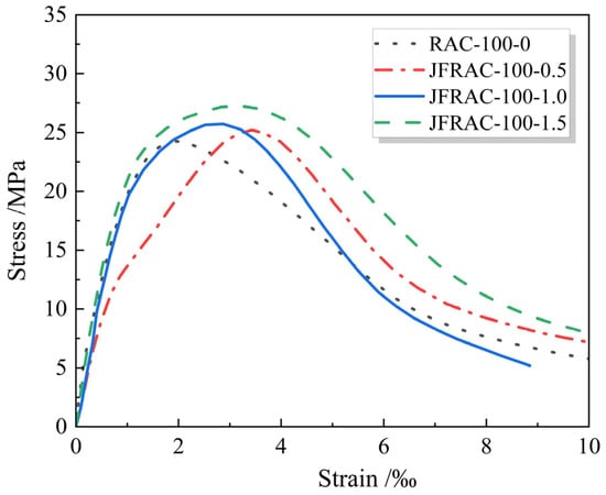
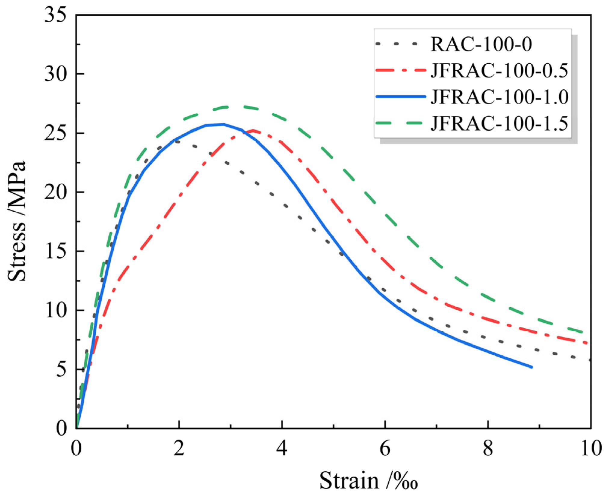
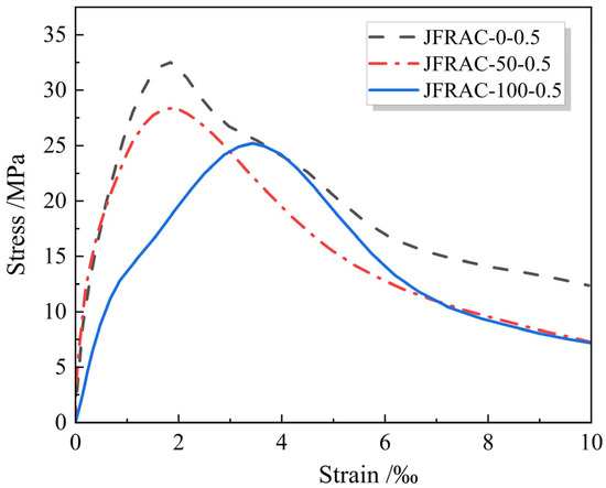
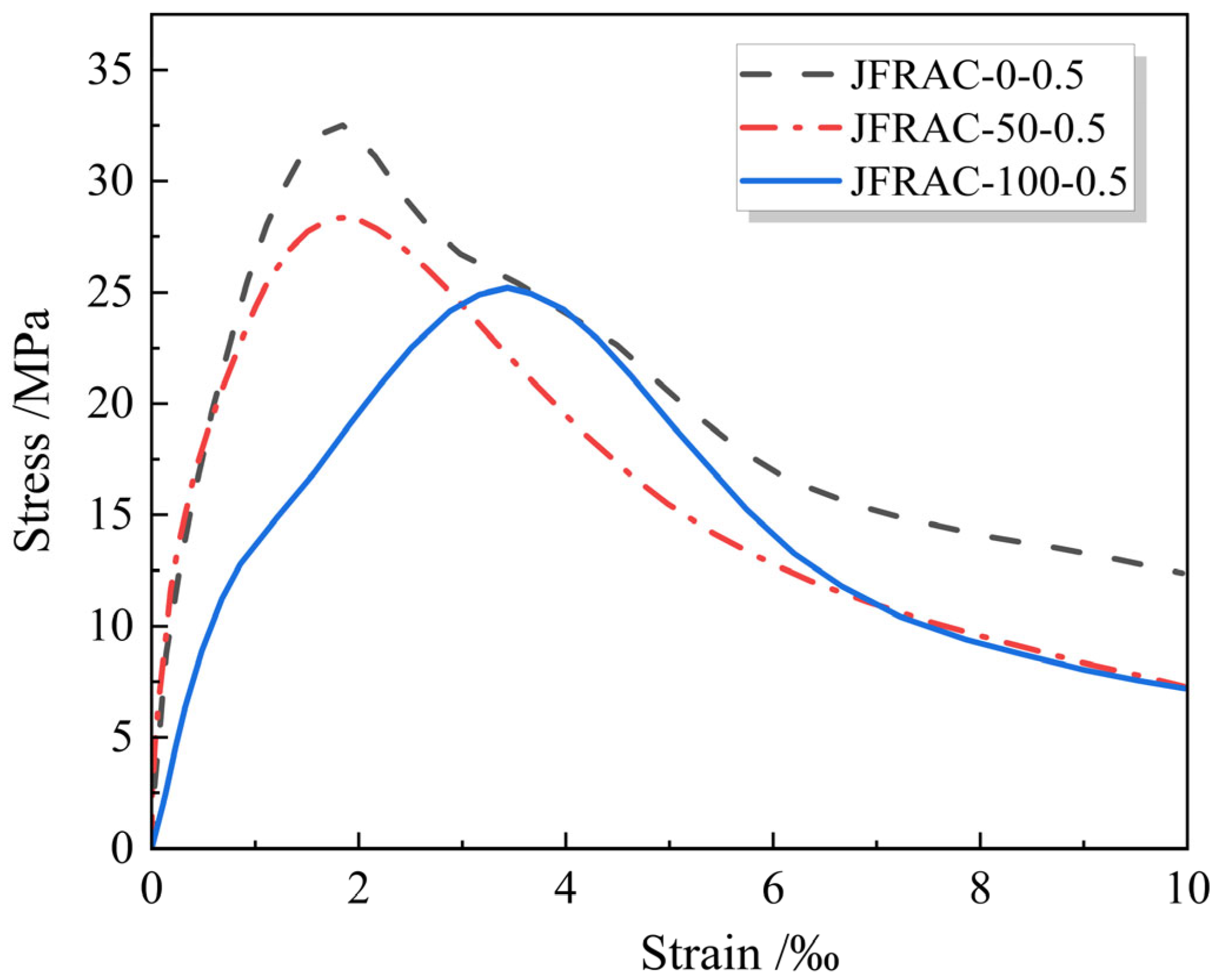
The compressive stress–strain curves of each specimen can be obtained from the axial load and displacement recorded during the loading process. The influences of jute fiber volume content (w) and RCA replacement rate (r) are summarized, as shown in Figure 3 and Figure 4. It can be observed from the figures that for C30 concrete, as the RCA replacement rate increases, the ascending branch of the curve becomes gentler, while the descending branch becomes steeper. In contrast, the incorporation of recycled fiber reduces the differences in the descending branch, and with increasing fiber content, the descending branch tends to become gentler, indicating that fiber addition effectively improves the brittleness of recycled concrete. Furthermore, as the fiber content increases, the peak value of the JFRAC gradually rises, and the descending branch becomes progressively gentler, demonstrating a significant improvement in the brittleness of recycled concrete. Additionally, as shown in Figure 4, for a jute fiber volume content of 0.5%, both the compressive strength and elastic modulus of plain recycled concrete decrease as the RCA replacement rate increases. However, after adding recycled jute fiber, both the compressive strength and elastic modulus of the recycled aggregate concrete are improved.
Figure 3.
Stress–strain relationship under different jute fiber volume contents.
Figure 4.
Stress–strain relationship under different recycled aggregate replacement rates.
Since elastic modulus and compressive strength are key parameters defining the mechanical behavior of the material, these parameters are incorporated into the model to define the stress–strain relationship of JFRAC. Accordingly, the elastic modulus and compressive strength results in Figure 3 and Figure 4 are summarized in Table 2.
Table 2.
Compressive strength and elastic modulus parameters.
2.2. Modified CDP Constitutive Model
2.2.1. Model Description
The CDP constitutive model is a classical constitutive model that reflects the plasticity and inelastic damage of concrete. According to the GB50010-2010 [44], the stress–strain curve of concrete under uniaxial tension in this model can be determined by the following formulas:
where σ is stress, ε is strain, dt is the concrete uniaxial tensile evolution parameter, and Ec is the concrete compressive elastic modulus.
where ft,r is the representative value of concrete uniaxial tensile strength, εt,r is the peak tensile strain of concrete, and αt is the parameter value for the descending segment of the concrete uniaxial tensile stress–strain curve, which can be selected according to the code.
The stress–strain curve for uniaxial compression can be determined by the following equation:
where dc is the concrete uniaxial compressive evolution parameter:
where fc,r is the representative value of concrete uniaxial compressive strength, εc,r is the peak compressive strain of concrete, and αc is the parameter value for the descending segment of the concrete uniaxial compressive stress–strain curve, which can be selected according to the code.
The aforementioned CDP constitutive model is proposed based on the constitutive relationship describing standard axial compression or tension specimens. It is difficult to reflect the influence of jute fiber content in JFRAC, nor can it reflect the effect of RCA replacement rate on its strength. Therefore, utilizing the aforementioned test data, a modified CDP constitutive model is established to describe the stress–strain relationship of JFRAC.
According to the aforementioned test results, the variation trend of stress with strain in JFRAC shares similarities with conventional concrete in that damage occurs when the strain increases to a certain extent. Furthermore, after adding jute fiber or RCA, the compressive strength of concrete is enhanced to some degree. Therefore, to describe the constitutive relationship of JFRAC, the fc and Ec in the CDP constitutive model are modified accordingly.
(1) Compressive strength
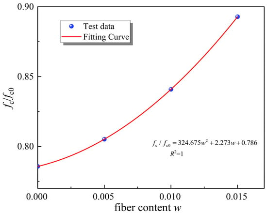
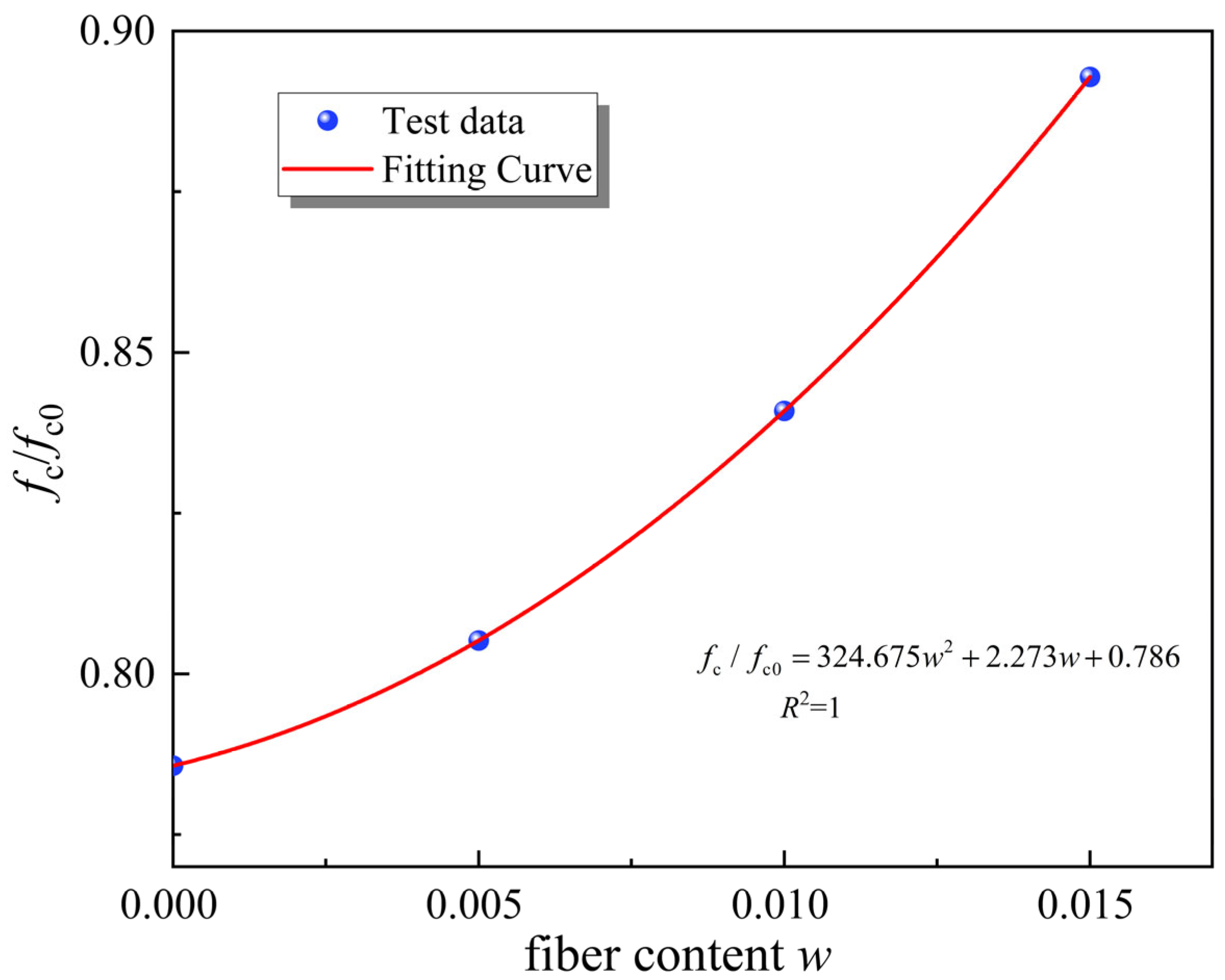
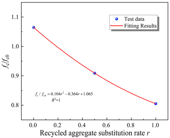
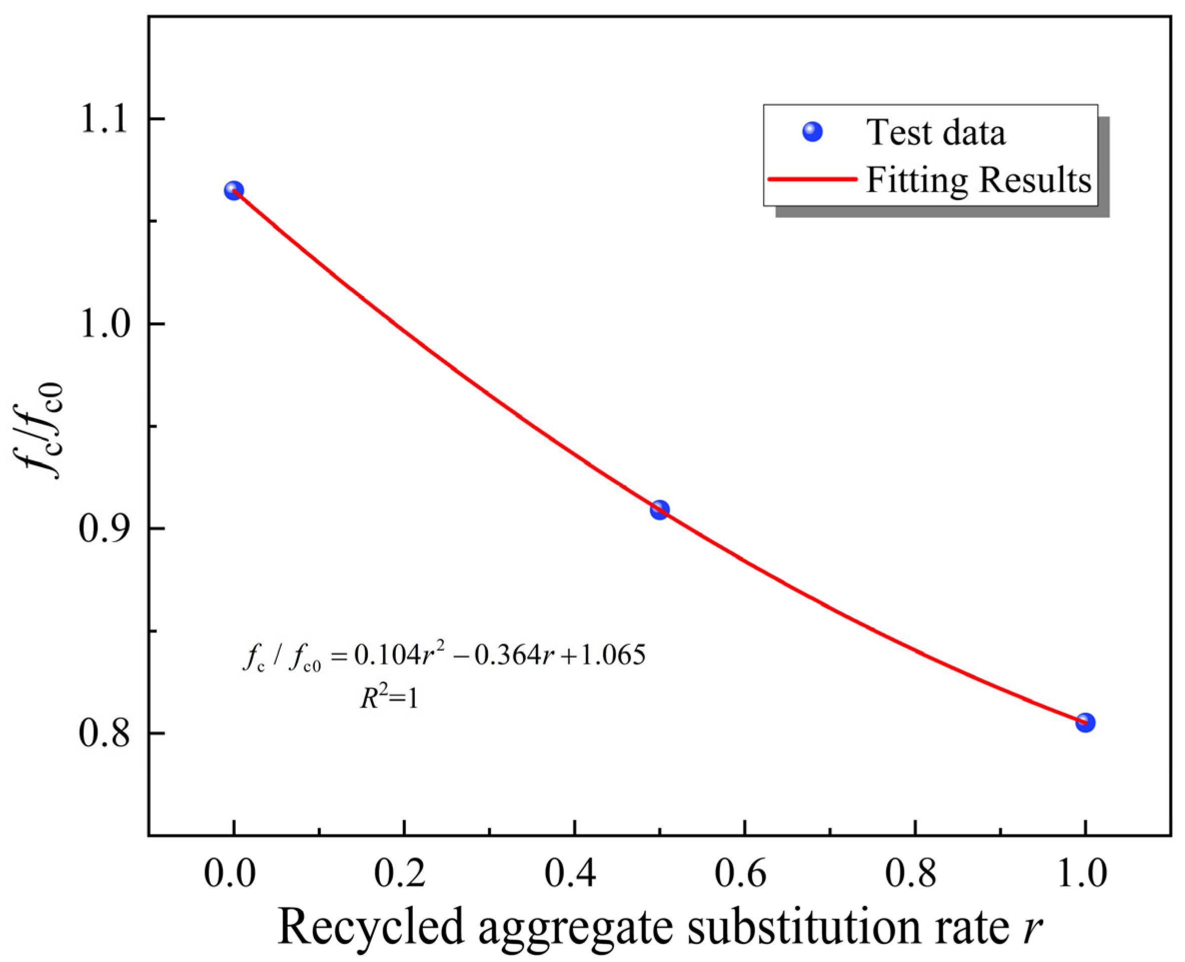
First, based on the concrete compressive strength of C30 (fc0 = 30.8 MPa), the compressive strength test results of JFRAC from Groups 2 and 5–7 were normalized. The relationship between jute fiber content and the normalized parameter fc/fc0 was established to describe the variation in compressive strength of JFRAC with jute fiber content, as shown in Figure 5 and Equation (10). Then, the relationship between concrete compressive strength and recycled aggregate replacement rate was predicted using the test results from Groups 3–5, as shown in Figure 6 and Equation (11).
Figure 5.
Relationship between compressive strength and jute fiber volume content.
Figure 6.
Relationship between compressive strength and recycled aggregate replacement rate.
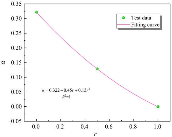
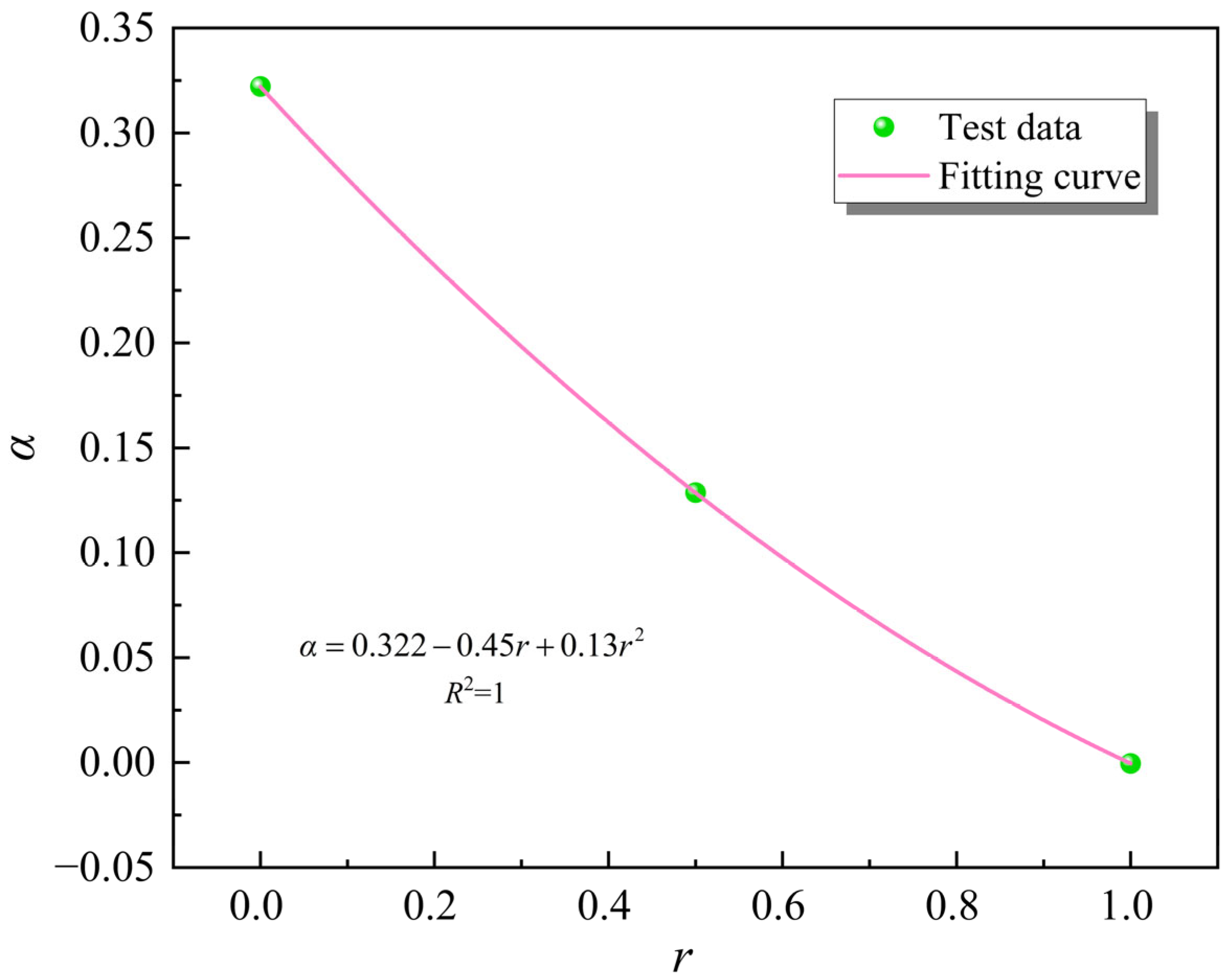
To comprehensively consider the effects of jute fiber volume content and recycled aggregate replacement rate on the JFRAC, regression analysis of the above results is required. After introducing the regression coefficient α into Equation (10), a fitting analysis was performed between α and the recycled aggregate replacement rate. The results are shown in Figure 7 and Equation (14).
Figure 7.
The relationship between the regression coefficient α and RAC replacement rate.
When substituting Equation (14) to Equation (12), the final predictive equation for the compressive strength of JFRAC can be obtained as shown in Equation (15). It should be noted that the coefficients in Equations (10)–(15) are derived from regression analysis of the normalized experimental data. They collectively represent the coupled effect of fiber content and recycled aggregate ratio. The final predictive equation (Equation (15)) is dimensionally consistent, as both the fiber volume ratio (w) and the recycled aggregate replacement rate (r) are dimensionless variables.
(2) Elastic modulus
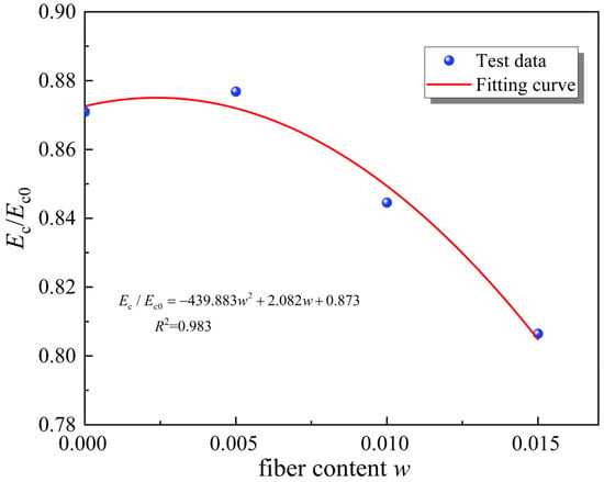
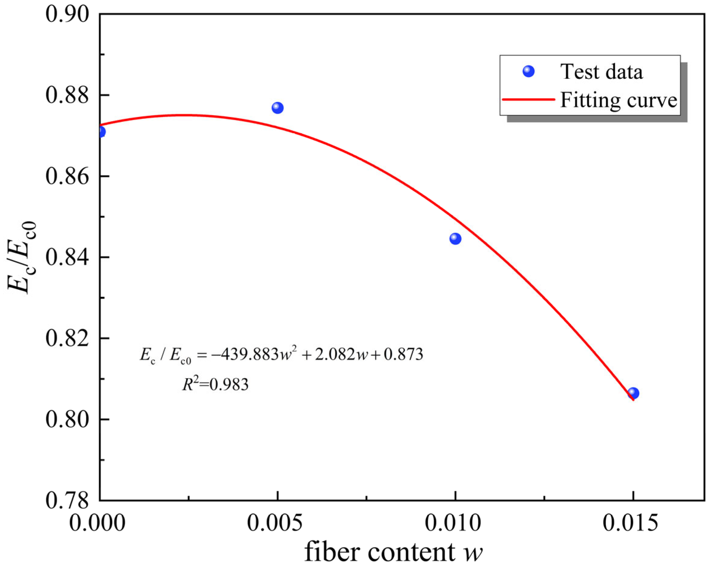
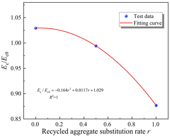
It is known that the elastic modulus is also one of the most important parameters in describing concrete characteristics. To quantity the difference in elastic modulus between JFRAC and C30, the test results of JFRAC from Groups 2 and 5–7 were normalized based on the value of C30 concrete (Ec0 = 34.1 GPa). The relationship between jute fiber content and the normalized parameter Ec/Ec0 was established to describe the variation in elastic modulus of JFRAC with jute fiber content, and this data was used to predict the relationship between them, as shown in Figure 8 and Equation (16). Then, using the test results from Groups 3–5, the relationship between concrete elastic modulus and RCA replacement rate was predicted, as shown in Figure 9 and Equation (17).
Figure 8.
Relationship between concrete elastic modulus and jute fiber volume content.
Figure 9.
Relationship between concrete elastic modulus and recycled aggregate replacement rate.
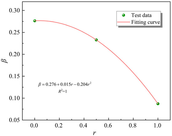
To comprehensively consider the effects of jute fiber volume content and recycled aggregate replacement rate on the elastic modulus of JFRAC, regression analysis of the above results is required. After introducing the regression coefficient β into Equation (16), a fitting analysis was performed between β and the recycled aggregate replacement rate. The results are shown in Figure 10 and Equation (20).
Figure 10.
The relationship between the regression coefficient β and RAC replacement rate.
The final predictive formula for the elastic modulus of JFRAC can be obtained as shown in Equation (21).
2.2.2. Model Validation
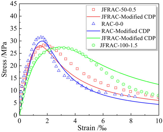
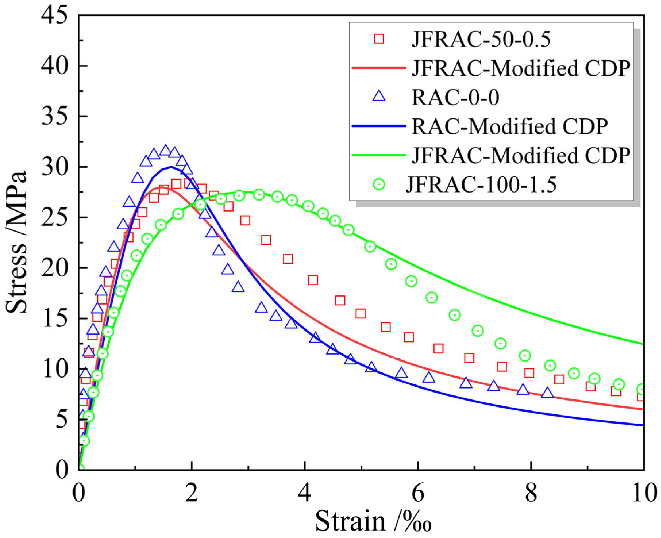
To verify the accuracy of the proposed modified CDP constitutive model for JFRAC, the modified CDP model was used to simulate the stress–strain relationships of concrete without recycled aggregate and jute fiber, a concrete with a RCA replacement rate of 100% and a jute fiber volume content of 1.5%, and a concrete with a recycled aggregate replacement rate of 50% and a jute fiber volume content of 0.5%, respectively. The comparison between simulated values and test data is shown in Figure 11. It can be observed from the figure that the simulated results for both concretes are in close agreement with the measured values. Specifically, for the concrete without RCA and jute fiber, both the simulated and measured peak stresses occur at a strain value of approximately 1.7%. Compared to the measured data, the error in the simulated peak stress is only 5%, which validates the accuracy of the model for predicting the constitutive relationship of JFRAC.
Figure 11.
The comparison of the stress–strain relationship between simulations and test data.
3. Performance of JFRAC in Precast Cable Trench Joints
This section focuses on the performance of JFRAC in precast cable trench joints and compares it with the performance, cost, and material carbon emissions of C30 concrete precast cable trenches. First, using the finite element software ABAQUS(2018), a numerical model of a precast cable trench joint containing JFRAC was established through the modified CDP model. Second, to clarify the impact of concrete materials’ properties on the structural performance of precast cable trench joints, the simulation was also conducted for the C30 concrete precast cable trench joint. The performance was compared with that of JFRAC. Finally, the cost, component performance, and material carbon emissions per meter of cable trench were compared and analyzed for both JFRAC and C30 concrete.
3.1. Finite Element Model
(1) Geometry model
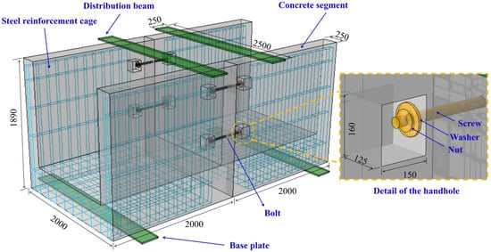
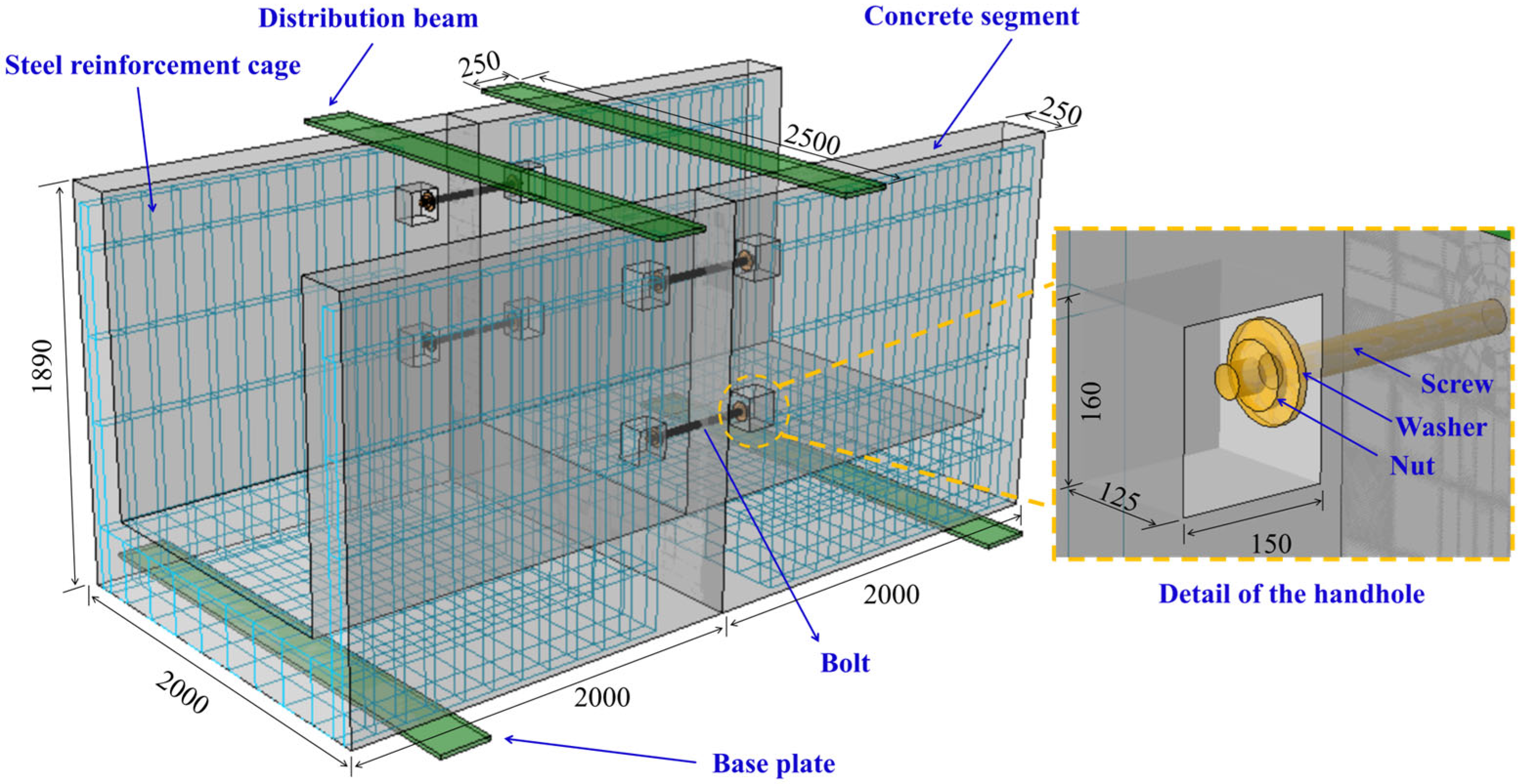
The finite element model was developed based on the standard dimensions of a typical precast cable trench joint used in Ningbo. To focus the analysis on the internal force distribution and damage-plastic deformation of the primary structure, and to prevent numerical non-convergence induced by excessive local contact pressure, the distribution beam was simplified into a 2500 mm × 250 mm × 20 mm plate. A displacement-controlled load was applied to this plate via a reference point coupled to its loading surface. The bolted connections were modeled as solid elements. The precast cable trench joints, which feature embedded nuts, have overall dimensions of 2000 mm × 2000 mm × 1890 mm. The connection between segments is achieved by a central bolted joint. The bolt assembly, modeled as a merged part, consists of a screw (500 mm in length, 30 mm in diameter), a nut (10 mm in thickness, 50 mm in diameter), and a washer (8 mm in thickness). This finite element model employs grade 8.8 bolts, and its parameters are shown in Table 3. In addition, there is an embedded reinforcement cage composed of HRB400 reinforcement. The cross-sectional diameters of the longitudinal bars, stirrups, and bottom longitudinal bars are all 10 mm. The specific dimensions and configuration of the model are illustrated in Figure 12.
Table 3.
Constitutive model parameters of bolt.
Figure 12.
Numerical simulation model schematic (Units: mm).
(2) Constitutive model
The material parameters adopted for the precast cable trench joint are summarized in Table 4. While the modified CDP model presented previously addresses key mechanical properties, such as compressive strength and elastic modulus, practical engineering applications necessitate a comprehensive consideration of additional factors, including concrete drying shrinkage and the environmental benefits of utilizing RCA. The significant influence of recycled aggregate on concrete shrinkage stress is highlighted, and the replacement ratio of RCA should not exceed 50%, as recommended in [45]. Thus, through a comprehensive comparison with the aforementioned predictive results for compressive strength, a replacement ratio of r = 40% was selected to optimize the consumption of waste RCA while maintaining performance.
Table 4.
Constitutive model parameters.
The cable trench structure employs JFRAC for its prestressed members. Based on the experimental data presented, the compressive strength of the reference C30 concrete was determined to be fc0 = 30.8 MPa. Adhering to the principle of equivalent strength design, the target compressive strength for the JFRAC was likewise set to fc = 30.8 MPa. The corresponding jute fiber content was calculated to be w = 1.4% according to Equation (15). Substituting the values of r and w into Equation (18) yields an elastic modulus of Ec = 33.73 GPa for the JFRAC. These derived parameters were subsequently incorporated into the modified CDP constitutive model to define the complete stress–strain relationship for the fiber-reinforced concrete. It is worth noting that the stress–strain relationship of concrete is not implemented through an embedded UMAT subroutine, but by directly adjusting certain parameters of the CDP constitutive model in ABAQUS, which facilitates the rapid application of the constitutive model.
(3) Contact
The numerical simulation model consists of two precast cable trench joints with identical geometric dimensions connected by solid bolts. The contacts between components in the model are as follows:
The screw, nut, and washer are modeled as a single integrated part to avoid excessive constraints that could lead to convergence issues in the calculation.
The interfaces between the bolt and the bolt holes of the precast concrete cable trench joint structure, as well as between the two precast concrete cable trench structures, are set as surface-to-surface contact. The normal behavior of the contact surfaces between concrete segments is defined as hard contact, transmitting only normal forces and allowing for separation with zero contact force upon detachment. The tangential behavior is based on Coulomb friction theory, using a penalty function to describe interfacial friction, with friction coefficients set to 0.2 and 0.3, respectively.
To prevent slippage between the washer and the concrete handhole, the contact surface between the concrete handhole and the washer is constrained using the “Tie” command in the software.
The interaction between the reinforcement skeleton and the concrete in each segment is implemented using the “Embedded Region” command in the software.
(4) Boundary conditions
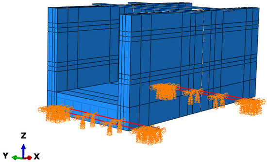
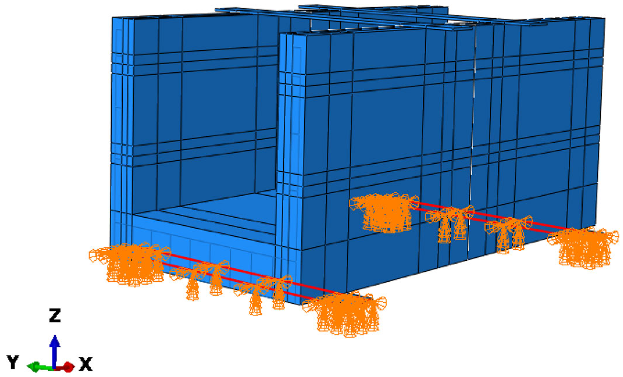
Based on the actual conditions, the boundary conditions of the numerical simulation model apply displacement constraints in the X, Y, and Z directions, as well as a rotational constraint about the Z-axis to the specimen base plate, as is highlighted in red in Figure 13.
Figure 13.
Boundary conditions of the model.
(5) Mesh
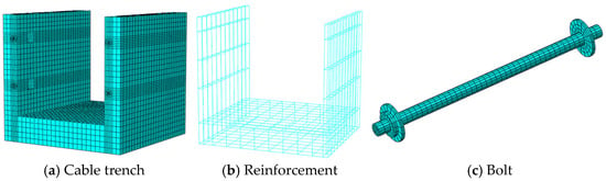
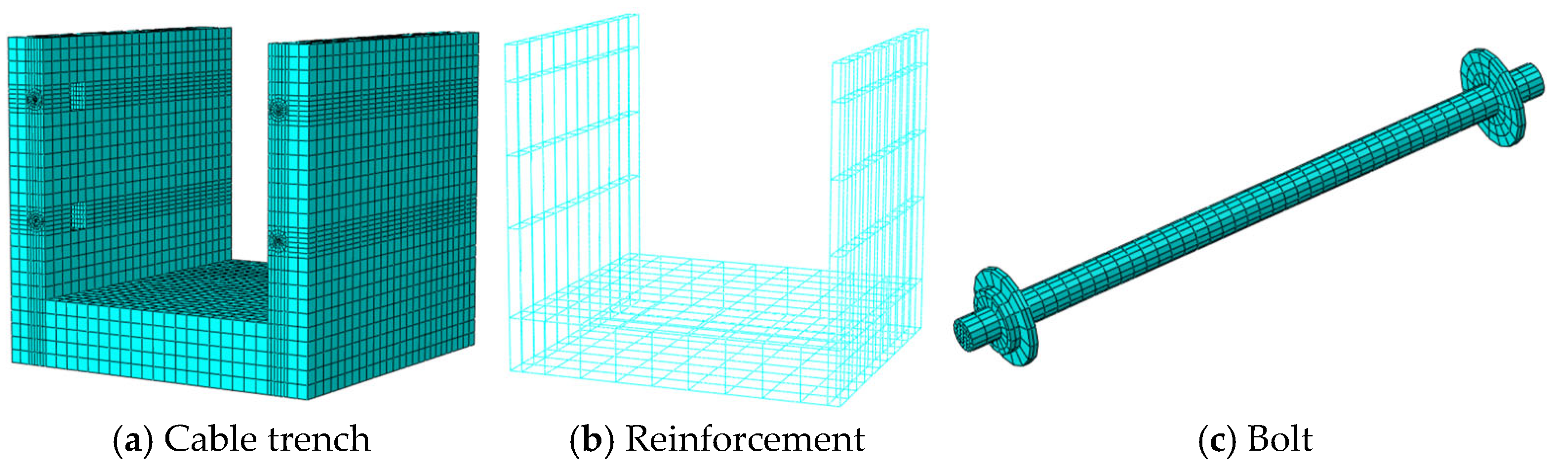
As shown in Figure 14, both the precast concrete components and bolts adopt C3D8 elements, while the reinforcement mesh uses T3D2 elements. The concrete regions of the precast cable trench and bolts in the finite element model are discretized with hexahedral meshes, generated using the structured method. The entire model consists of 56,196 elements.
Figure 14.
Mesh diagram of the model.
(6) Load application
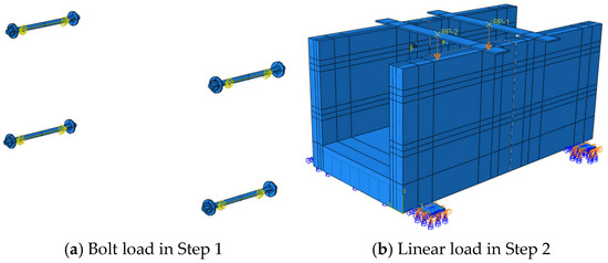
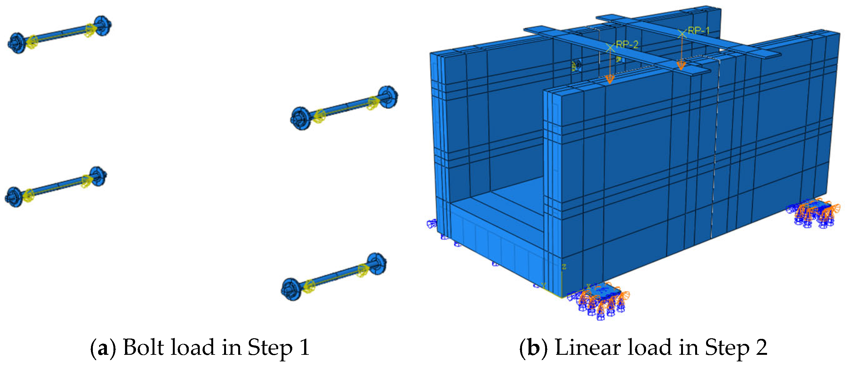
The model in this study is analyzed using the ABAQUS/Standard solver module. Two main analysis steps are set up. In Step 1, a preload of 70 kN is applied to the bolts. In the ABAQUS model, there are two primary methods for applying bolt preload: the Bolt Load (applied to the screw) method and the preload application method using the temperature reduction approach. The Bolt Load application method is as follows: a cut is made at the midpoint of the screw section of the solid bolt, and this section is selected as the loading surface for the bolt load. The load is applied to this surface by selecting “Bolt Load” in the Load module.
After Step 1 is completed and the bolt preload is fully applied, the simulation proceeds to Step 2. This stage involves the process of loading the specimen by the distribution beam. There are two aspects: one is that, since bolt preload has ended, the preload applied to the bolts needs to be removed; the other is the application of a linear load on the specimen. First, the bolt preload in Step 2 is eliminated using the “maintain current length” setting for bolt preload in ABAQUS. Second, using the Coupling command, the reference point is coupled to the contact surface between the pre-simplified distribution beam and the specimen, and a displacement of 30 mm is applied to the specimen. The load application methods in the two analysis steps are shown in Figure 15. In addition, two vertical force are added in the distribution beam through two reference points (RP-1 and RP-2) in Step 2 by strain controlling method.
Figure 15.
The load application methods in ABAQUS.
3.2. Numerical Results of the JFRAC
(1) Failure mode
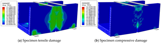
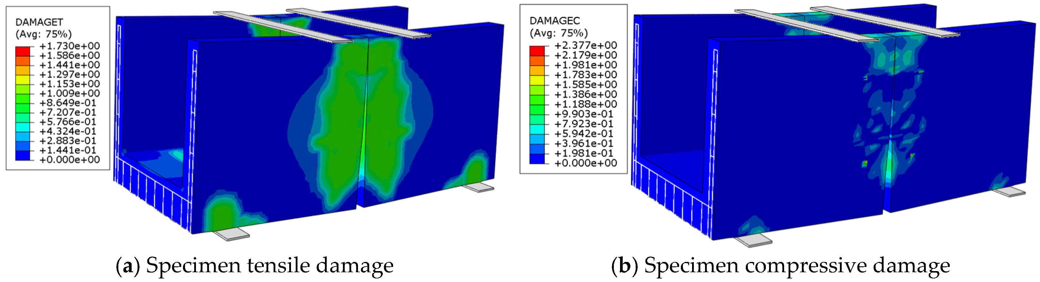
The numerical simulation results can show the failure modes of the specimen under tension and compression. Figure 16 and Figure 17, respectively, display the tensile- and compressive-damage conditions of the specimen after loading, as well as the Mises stress distribution of each component. Among them, DAMAGET and DAMAGEC are the results of the tensile damage factor dt and compressive damage factor dc, respectively. They are used to describe the distribution of tensile and compressive damage in the components during deformation.
Figure 16.
The tensile and compressive distribution of the specimen.
Figure 17.
Mises stress of each component (Unit: MPa).
Figure 18 shows the concrete stress development process in the finite element model of the precast concrete cable trench structure. As shown in the figure, the concrete stress in the specimen is mainly distributed in the compressive zone at the top of the concrete. As the load continuously increases, the concrete stress in the compressive zone at the top continues to increase and extends downward, while the concrete stress at the handhole and the middle of the cable trench structure also develops progressively. Therefore, reinforcement should be densified in these areas to prevent tensile failure of the concrete.
Figure 18.
Concrete connection joint specimen tensile damage progress.
(2) Load–displacement curve
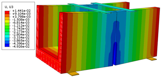
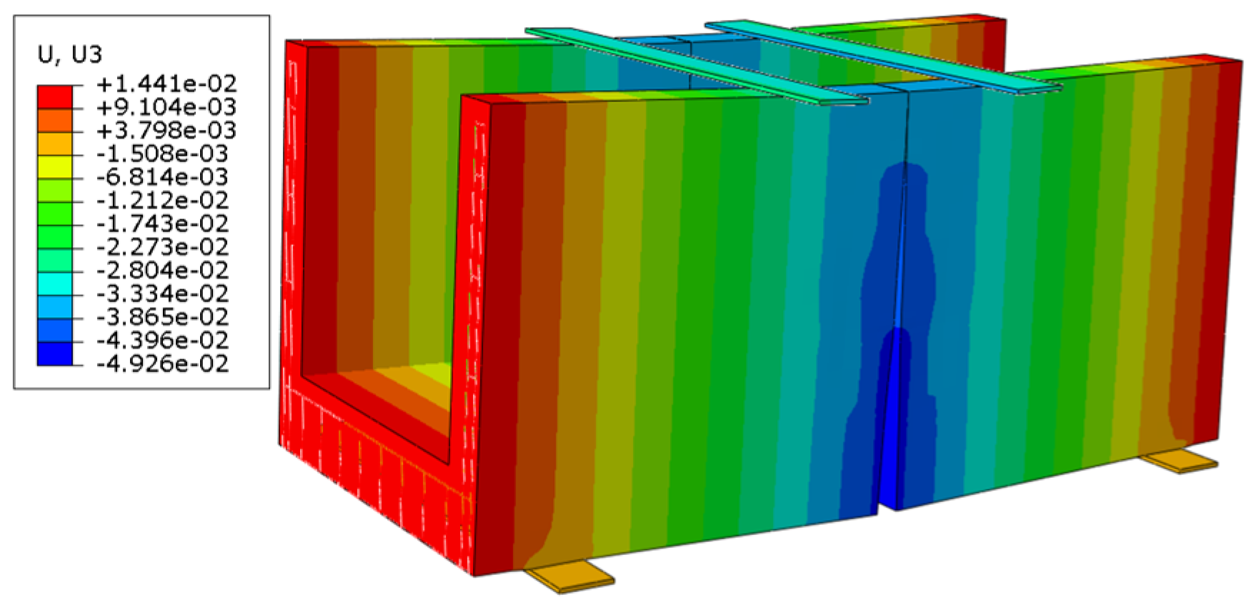
Figure 19 shows the vertical displacement of the numerical model. As shown below, the maximum displacement occurs at the midspan of the specimen, measuring 49.26 mm, which is consistent with the loading conditions.
Figure 19.
Z-direction displacement of the precast cable trench joint (unit: m).
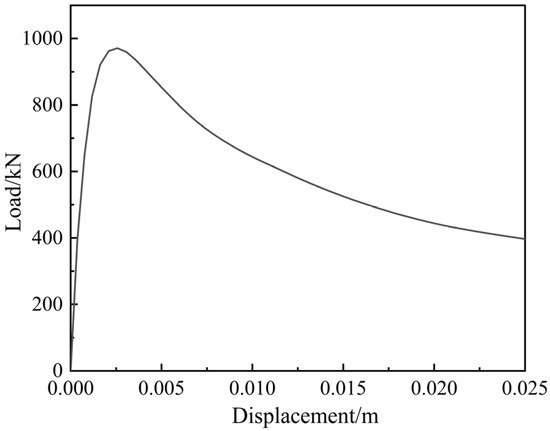
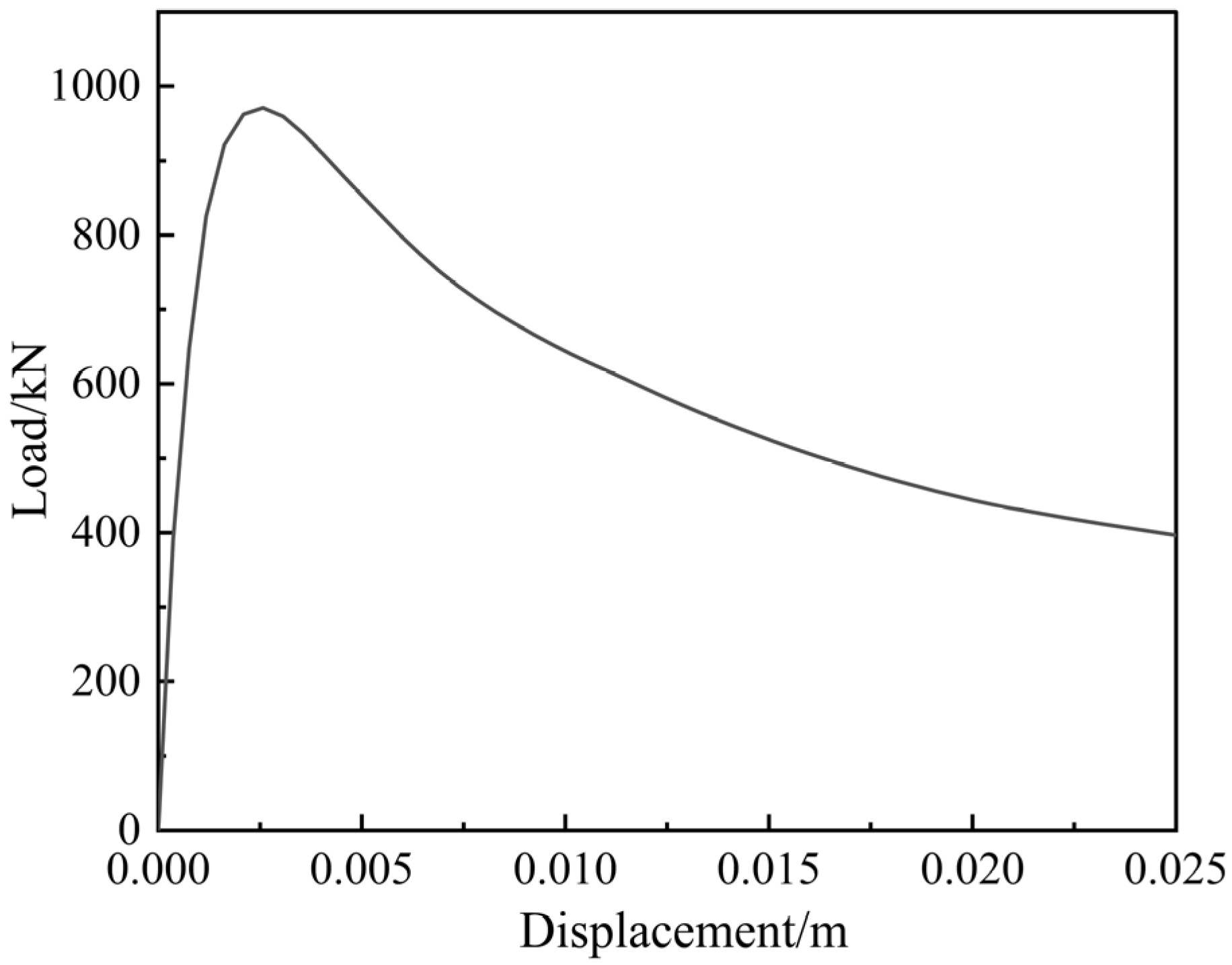
The load–displacement relationship at the midspan position of the specimen is shown in Figure 20. As shown, the capacity of the precast cable trench joint is no more than 1000 kN. In addition, distinct elastic, deformation development, and plastic damage stages can be observed in the load–displacement curve of the specimen.
Figure 20.
Simulated load–displacement curve in the midspan of the precast cable trench joint.
3.3. Comparison of JFRAC and C30 Concrete
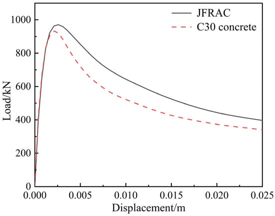
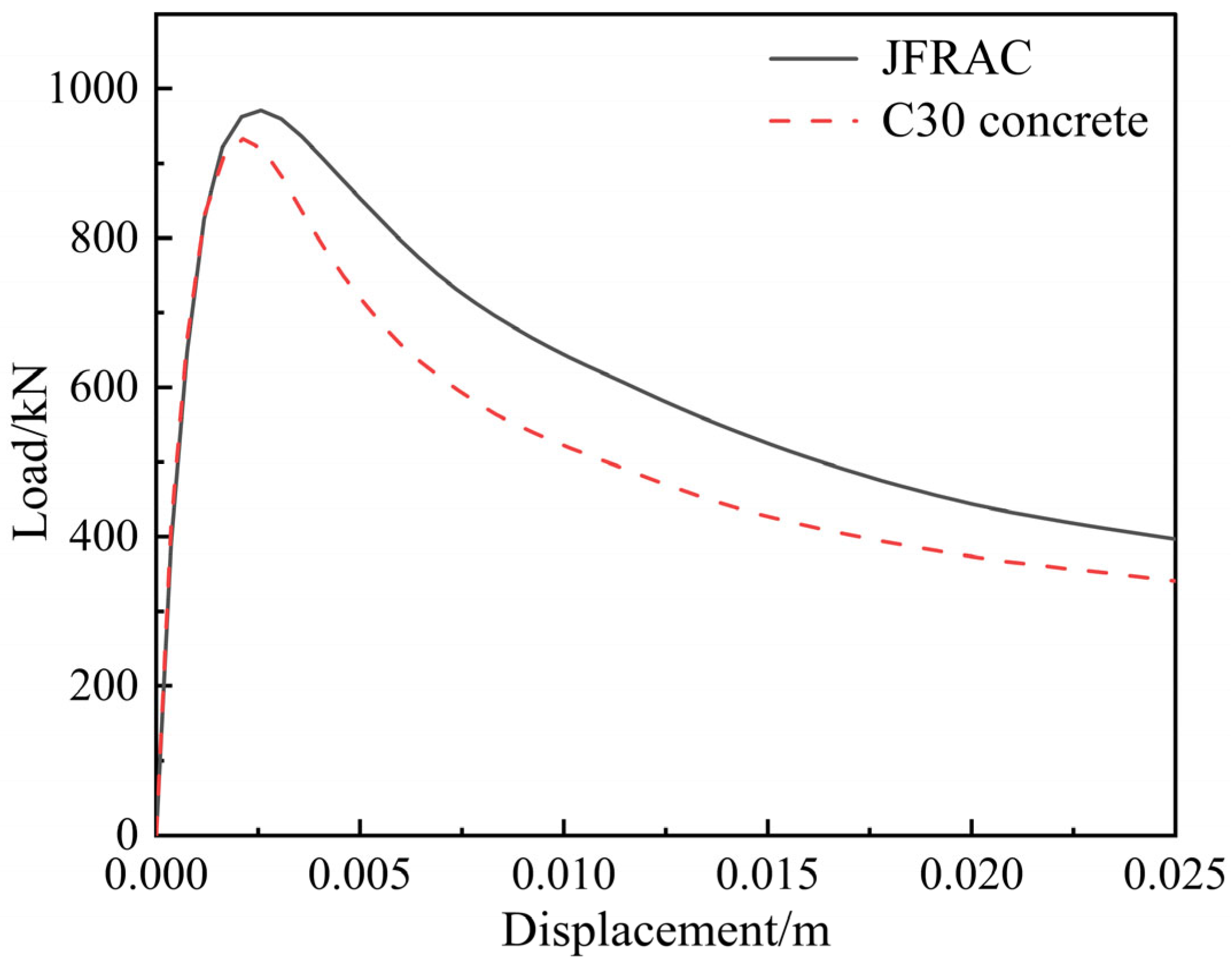
Figure 21 presents a comparison of the load–deformation curves at the midspan of precast cable trench joints made with JFRAC and conventional C30 concrete. It can be observed from the figure that the JFRAC exhibits a higher ultimate load-bearing capacity compared to conventional C30 concrete, along with a more gradual plastic failure stage. This behavior is attributed to the ability of the fibers within the precast JFRAC component to continue resisting deformation even after the concrete matrix has cracked.
Figure 21.
Comparison of simulated results from midspan of C30 and JFRAC.
In the JFRAC precast members, the fibers retain the ability to resist deformation even after the concrete matrix has cracked. As a result, the ultimate bearing capacity, peak displacement, and ductility are increased by 4.17%, 18.78%, and 14.66%, respectively, compared with C30 concrete members. However, due to the partial replacement of aggregates by fibers in the fiber-reinforced concrete, the overall elastic modulus is reduced, leading to a 1.65% decrease in flexural rigidity relative to C30 concrete. Detailed numerical comparisons of these properties are provided in Table 5.
Table 5.
The comparison in structural performance.
A comparative cost analysis during the production of a precast cable trench joint unit (4000 mm × 2000 mm ×1890 mm) is presented in Table 6. It is worth mentioning that the costs of recycled fibers and recycled coarse aggregates in Table 6 are both zero. This is because they are derived from either construction waste or discarded woven bags, and are considered waste utilization. Therefore, their costs are not included in JFRAC. The results demonstrate that employing JFRAC yields cost savings of CNY 62.43 per meter of the cable trench structure compared to C30 concrete.
Table 6.
The comparison of costs.
A comparative carbon emission analysis during the production of a precast cable trench joint unit (4000 mm × 2000 mm ×1890 mm) is presented in Table 7. Current studies reported that the carbon emissions of cement, RCA, and recycled jute fiber during production were 800~950 CO2ekg/t [46,47,48], −16 CO2ekg/t [49], and −80~−120 CO2ekg/t, respectively [50]. Based on this, JFRAC in precast cable trench joints is expected to reduce carbon emissions per meter of the cable trench structure by 2.29% compared with C30 concrete.
Table 7.
The comparison of carbon emissions.
The above analysis of precast cable trench joints using JFRAC and C30 concrete materials illustrates that JFRAC precast cable trench components can replace C30 concrete in terms of mechanical performance. Moreover, JFRAC is superior to C30 concrete in terms of cost and the carbon emissions of raw materials. JFRAC’s raw materials utilize recycled jute fibers and recycled concrete made from construction waste, making its application in prestressed cable trench components very beneficial for environmental sustainability.
4. Discussion
In this section, to clarify the effect of the bolt in the JFRAC precast cable trench joints, finite element simulations were conducted under different conditions of bolt strength grade, bolt preload, bolt diameter, and number of bolts to clarify the influence of these factors on the performance of bolted connection joints in precast concrete cable trench structures. The concrete parameters were set according to the JFRAC, as detailed in Section 3.1. The parameters of the bolt are listed below.
4.1. Bolt Grade
To investigate the effect of bolt grade on the performance of the JFRAC precast cable trench joint, bolt grades of 4.6, 5.6, 8.8, and 10.9 were selected to establish four finite element models. And the constitutive parameters for each bolt strength grade are set as shown in Table 8. Other parameters remain the same as the model in Section 3.
Table 8.
Bolt parameters across different grades.
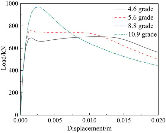
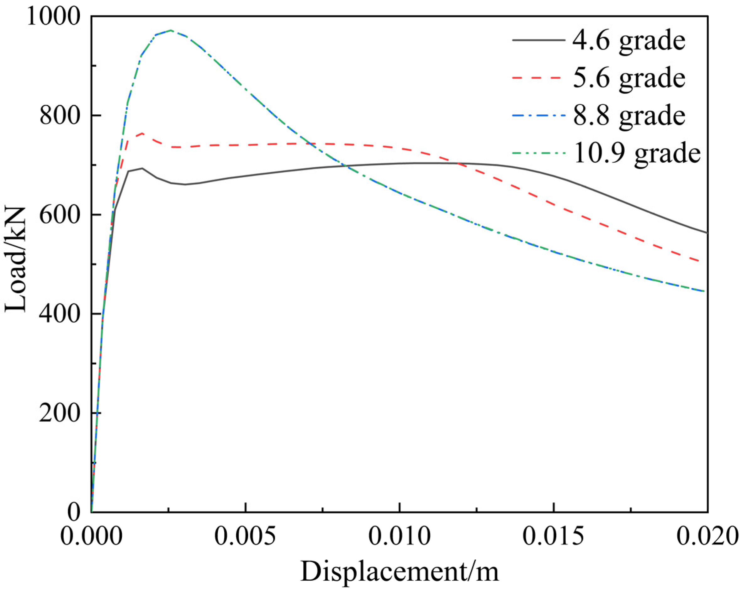
Figure 22 shows the simulation results of different bolt grades on the bending load–displacement curve in the midspan of the precast concrete cable trench joint. As observed in the figure, as the bolt grade increases, the ascending branch of the curve also increases, while the descending branch becomes steeper. This indicates that, although high-strength bolts can significantly enhance the initial bending stiffness of the structure, allowing it to exhibit higher load-bearing capacity under loading, they also cause the structure to enter the failure stage more rapidly. Notably, when the bolt grade increases beyond 5.6, the peak of the curve shows a precipitous rise, with the peak load increasing from 763.67 kN to 971.29 kN. This demonstrates that bolt grade has a significant impact on the bending performance of the bolted connection joints in the precast concrete cable trench structure.
Figure 22.
Load–displacement curves of different bolt grades.
When the bolt grade reaches 8.8 or higher, the load–displacement curve shows almost no change. This may be because, at a bolt grade of 8.8, the structure has already reached its ultimate bearing capacity, and further increases in bolt grade have minimal effect on the ultimate load-bearing capacity.
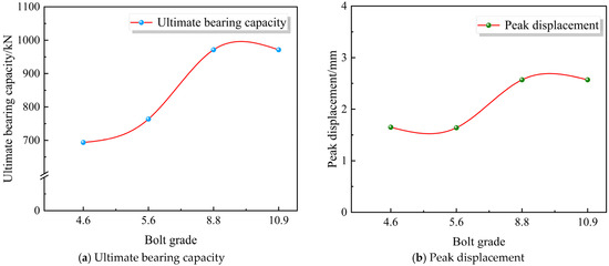
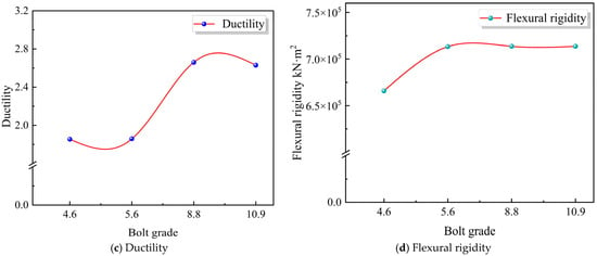
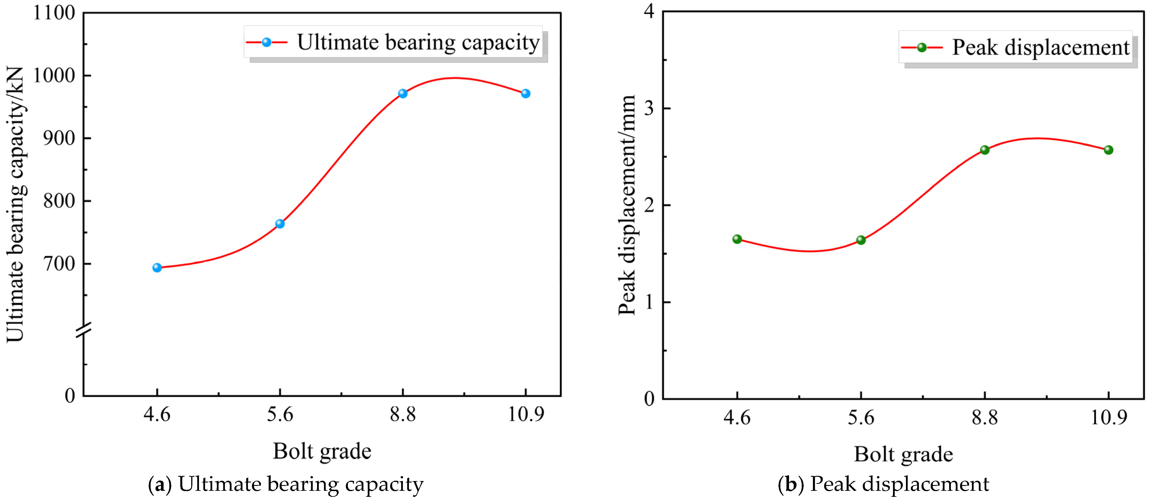
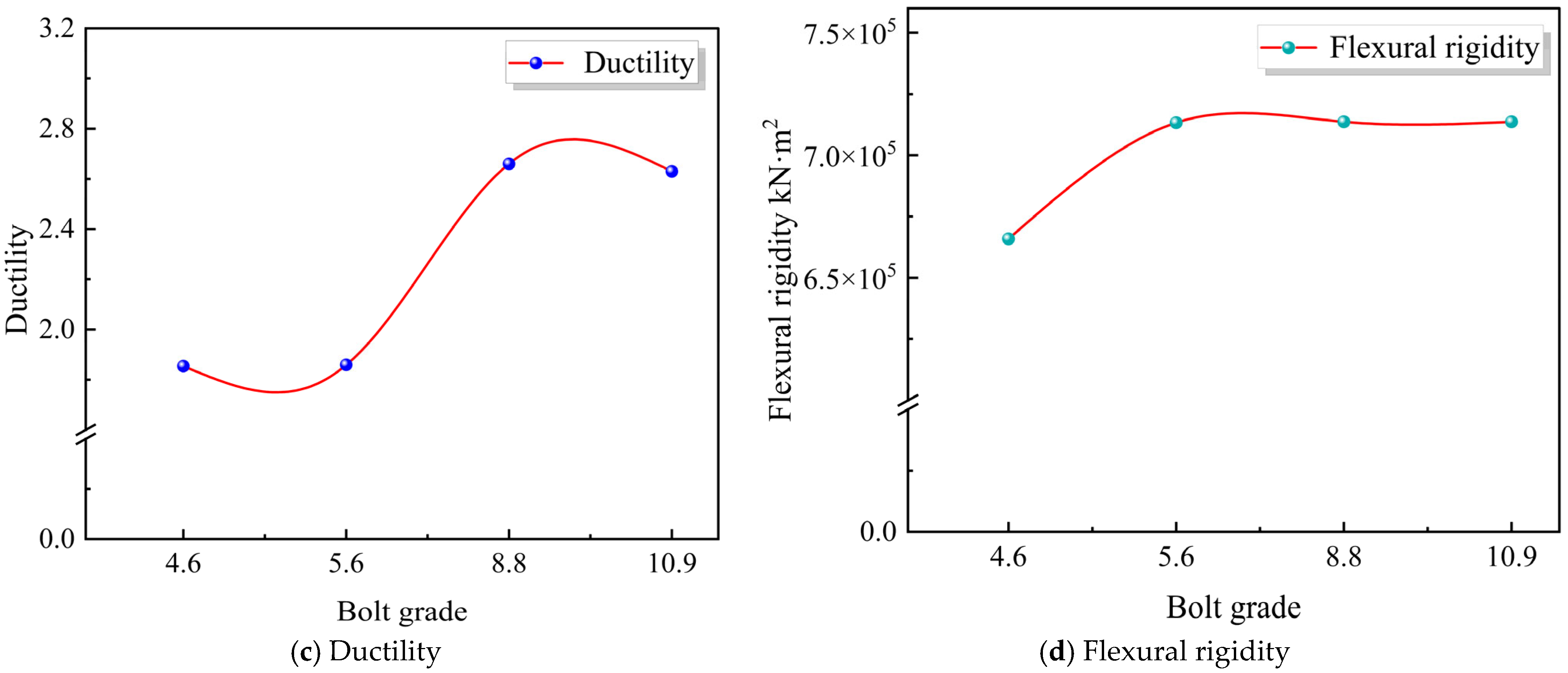
Figure 23 shows the influence of different bolt grades on the flexural performance of bolted connection joints in precast concrete cable trench structures. As observed in the figure, with the increase in bolt grade, the ultimate bearing capacity, peak deflection, and stiffness of the specimens all increase continuously. The ultimate bearing capacity increases from 693.31 kN to 971.29 kN, showing significant growth when the bolt grade exceeds 5.6, indicating that high-strength bolts play a remarkable role in enhancing the structural flexural performance. The ductility of the specimens shows an increasing trend, rising from the initial 1.854 to 2.63. This demonstrates that high-strength bolts can not only enhance the overall stiffness and load-bearing capacity of the structure but also improve its deformation capacity.
Figure 23.
Influence of bolt grade on mechanical properties of specimens.
4.2. Bolt Preload
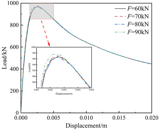
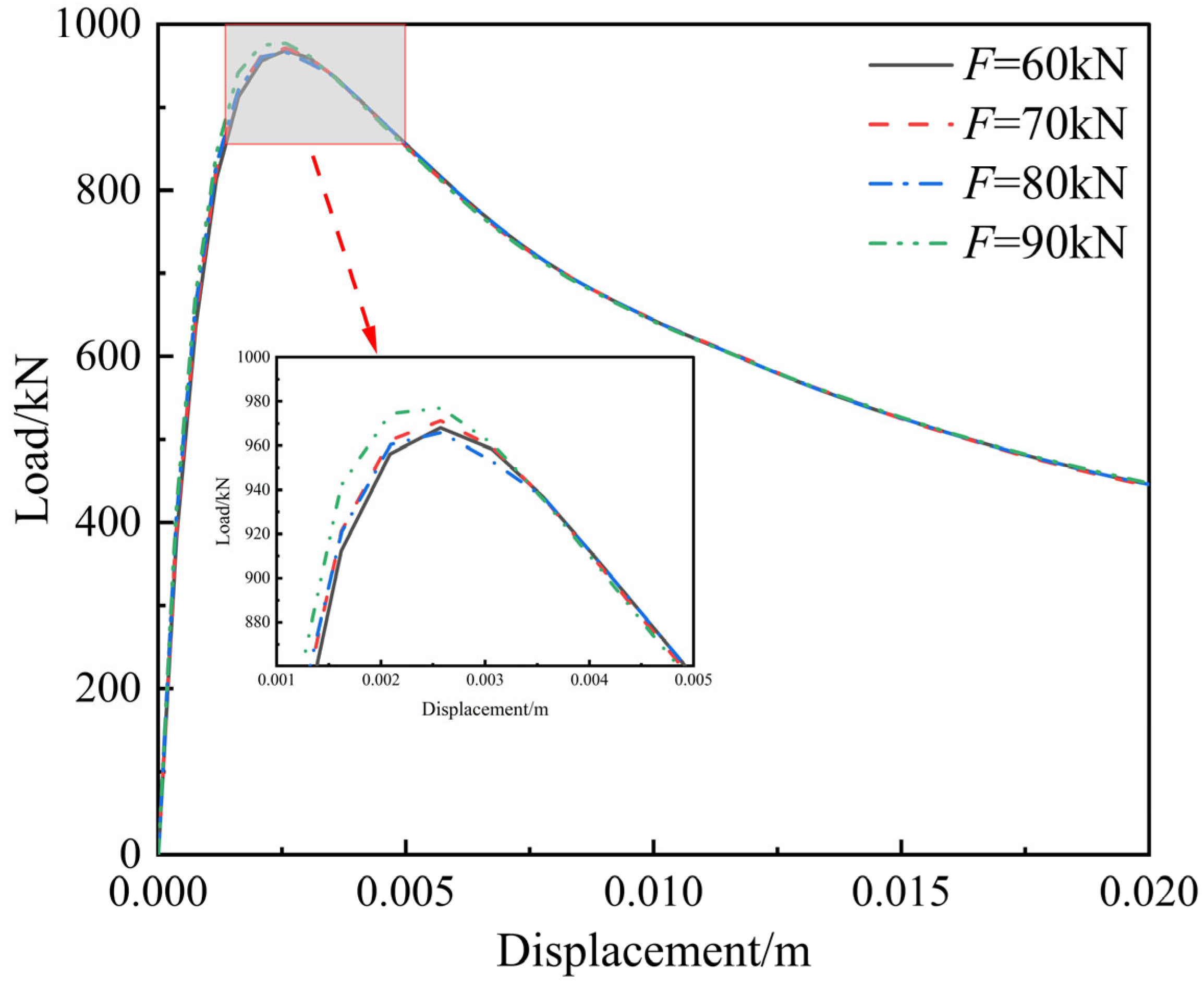
To study the effect of bolt preload on the performance of the JFRAC precast cable trench joint, bolt preloads of 60 kN, 70 kN, 80 kN, and 90 kN were selected to establish four finite element models. Figure 24 shows the simulated results of different bolt preloads on the bending load–displacement curve of the bolted connection joints in the precast concrete cable trench structure. As observed in the figure, the bolt preload has a minor effect on the specimen curve. The peak load increases from 968.2 kN to 974.65 kN, and the characteristic load-deflection values at each stage of the curves basically coincide.
Figure 24.
Load–displacement curves of different bolt preloads.
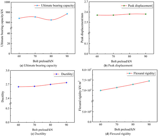
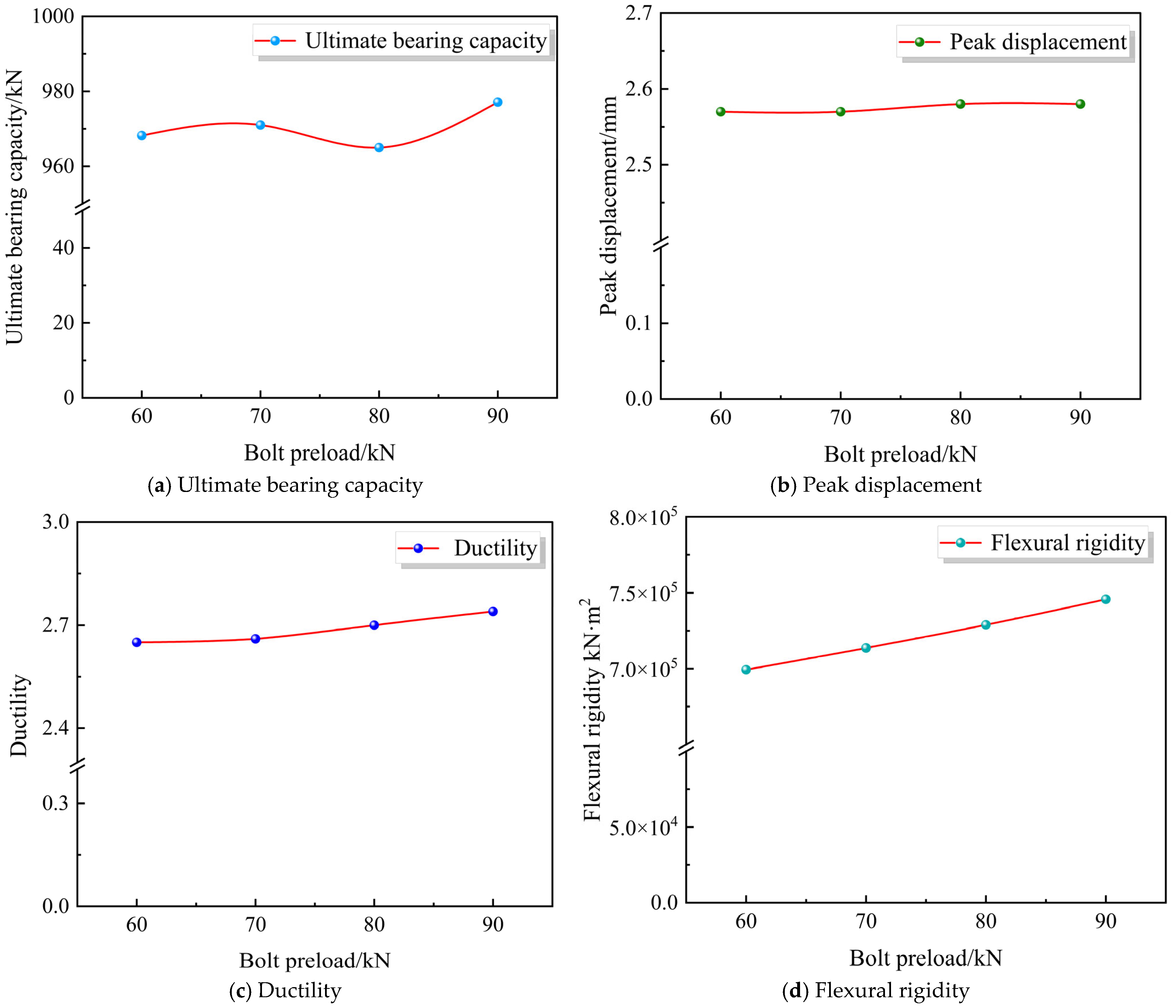
Figure 25 shows the influence of different bolt preloads on the flexural performance of bolted connection joints in precast concrete cable trench structures. As observed in the figure, the peak deflection, ductility, and flexural rigidity of the specimens exhibit a slowly increasing trend. The ultimate bearing capacity fluctuates within a range of 15 kN, but the overall influence is not significant. This indicates that changes in bolt preload do not cause a notable alteration in the bearing capacity of the specimens under ultimate conditions, while an increase in bolt preload can slightly improve the overall stiffness and deformation capacity of the specimens.
Figure 25.
Influence of bolt preload on mechanical properties of specimens.
4.3. Bolt Diameter
To investigate the effect of bolt diameter on the performance of the JFRAC precast cable trench joint, bolt diameters of 28 mm, 30 mm, 32 mm, and 34 mm were selected to establish four finite element models. And the other parameters of the model remain the same as the model in Section 3.
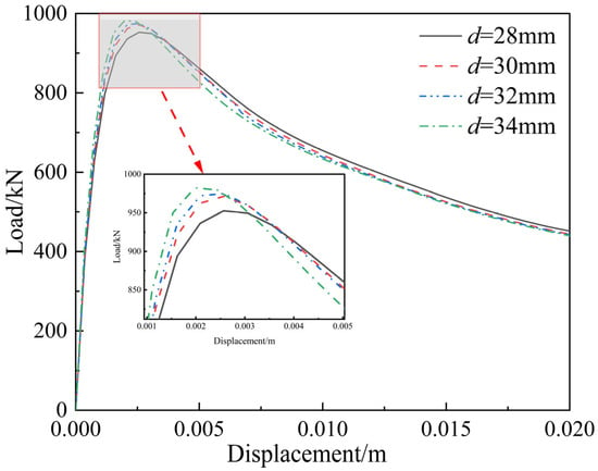
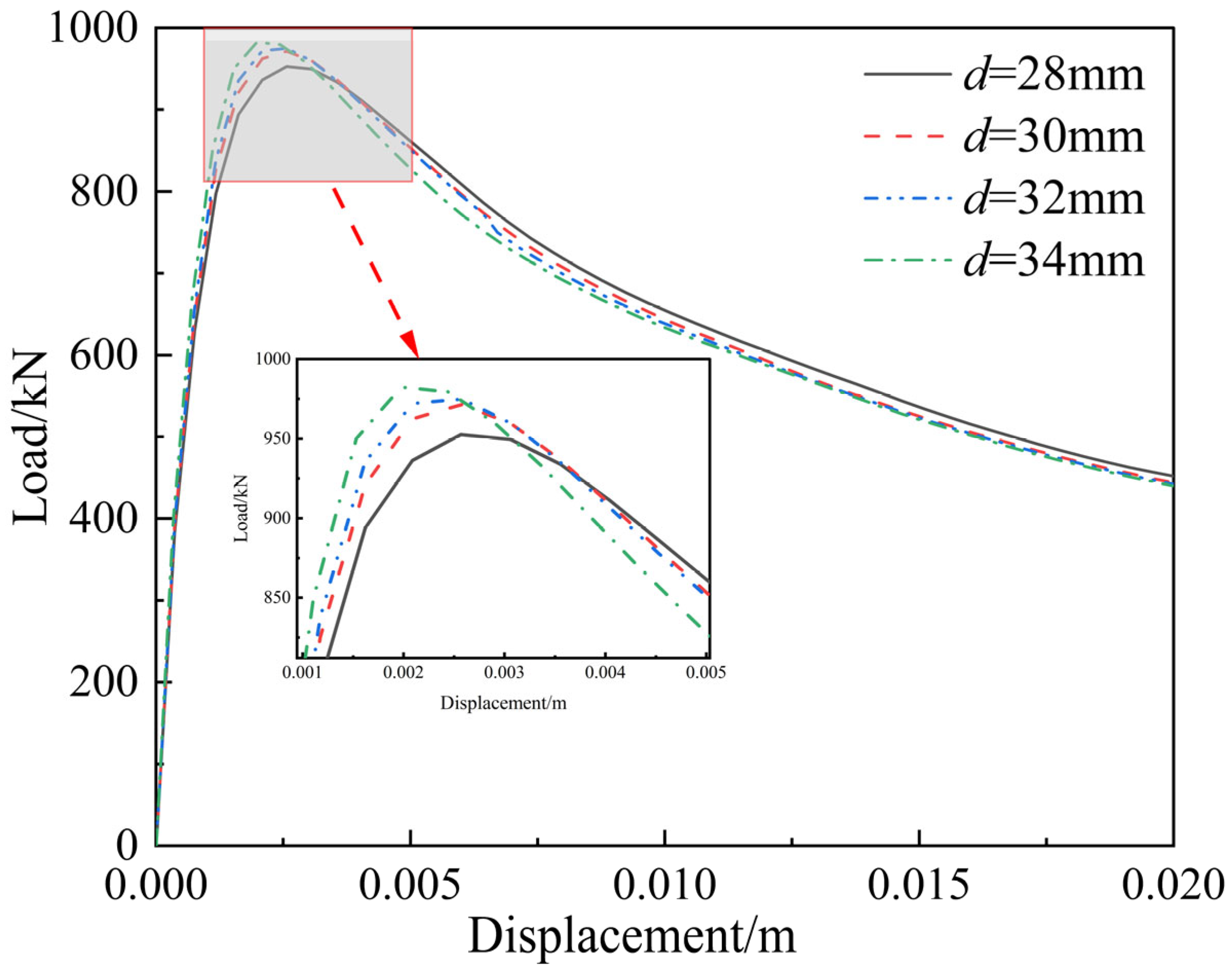
Figure 26 shows the simulation of different bolt diameters on the bending load–displacement curve of the bolted connection joints in the precast concrete cable trench structure. It is observed that the ascending branch of the load–displacement curve increases with larger bolt diameters, with the peak load rising from 952.61 kN to 982.42 kN. This indicates that the initial stiffness of the specimens continuously increases with larger bolt diameters. Simultaneously, the descending branch becomes progressively steeper with increasing bolt diameter, suggesting that specimens with larger diameters experience faster stiffness degradation and more severe damage in the later stage.
Figure 26.
Load–displacement curves of different bolt diameters.
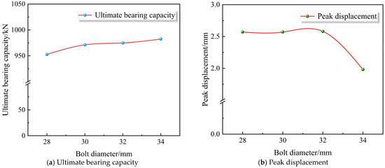
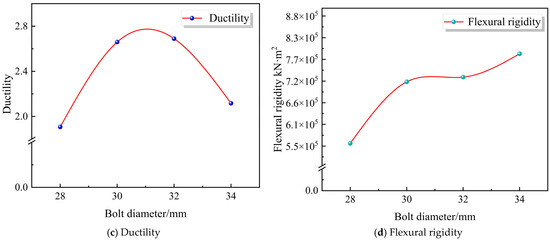
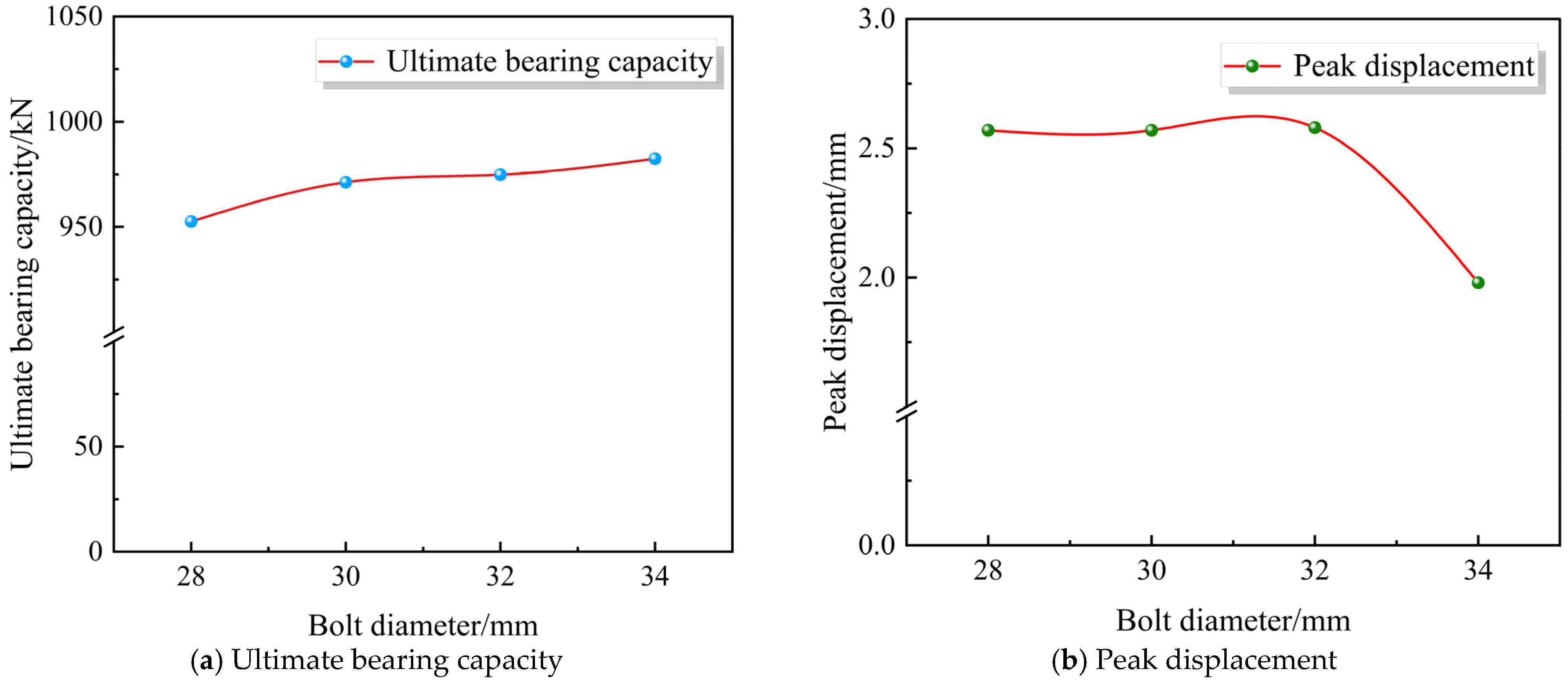
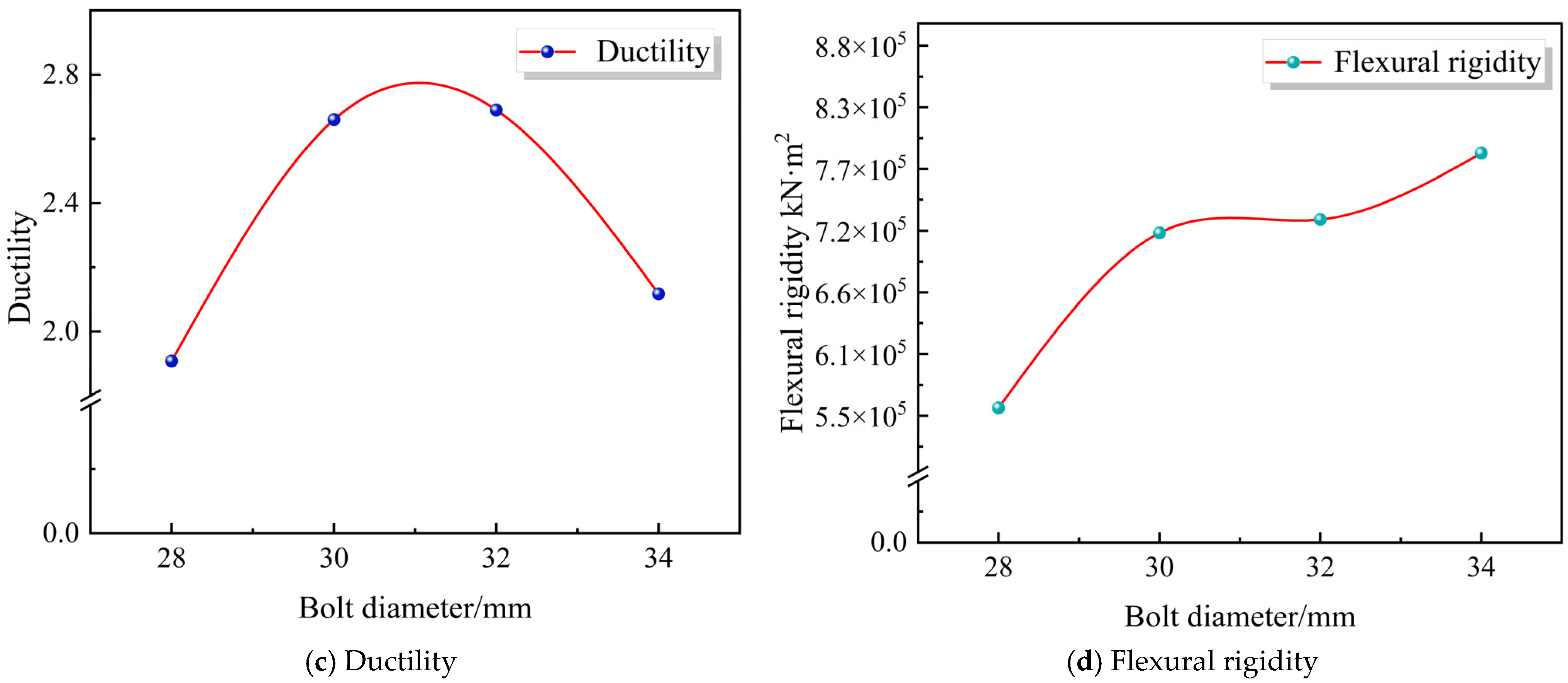
Figure 27 shows the influence of different bolt diameters on the flexural performance of bolted connection joints in precast concrete cable trench structures. As observed in the figure, with the increase in bolt diameter, the ultimate bearing capacity, ductility, and flexural rigidity of the specimens all exhibit a linear growth trend. The ultimate bearing capacity increases from 952.61 kN to 982.42 kN; the flexural rigidity reaches up to 7.84 × 10⁵ kN·m2. When the bolt diameter is 32 mm, the ductility significantly improves from 1.9 to 2.69, but decreases when the bolt diameter becomes excessively large. This indicates that appropriately increasing the bolt diameter can enhance the specimen’s resistance to bending deformation and load-bearing capacity. However, excessively large bolt diameters create strong constraints between specimens, thereby inhibiting plastic deformation and ultimately reducing the specimen’s deformation resistance. Meanwhile, the peak deflection of the specimens decreases linearly from 2.58 to 1.98. The reason for this phenomenon may be that larger-diameter bolts have higher connection strength, which better distributes and transfers internal stresses in the specimen, thereby reducing the amount of deformation.
Figure 27.
Influence of bolt diameter on mechanical properties of specimens.
4.4. Bolt Number
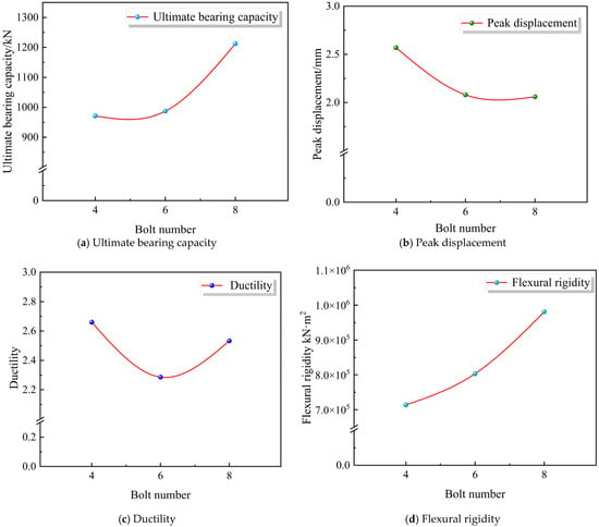
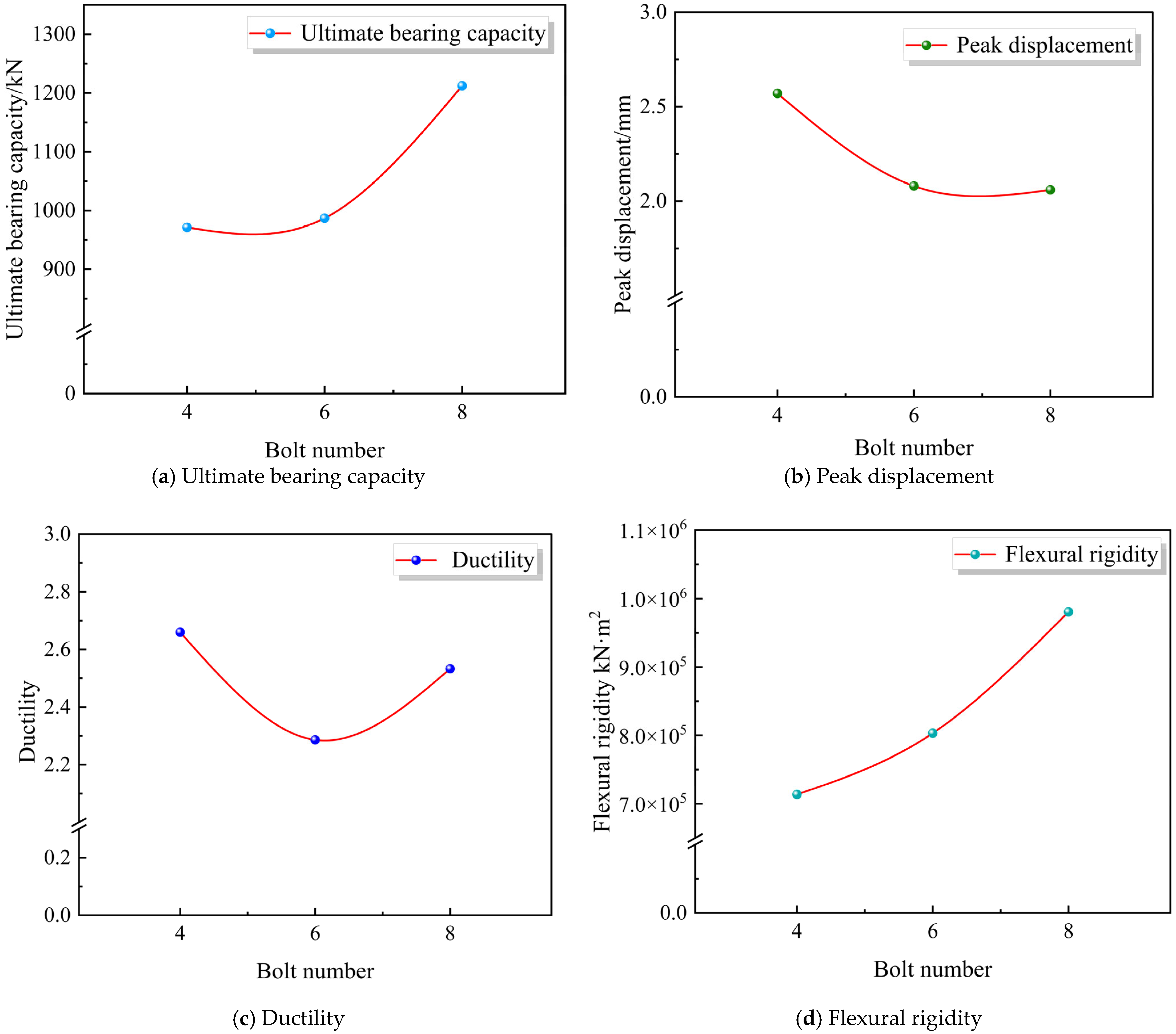
To investigate the effect of bolt number on the performance of the JFRAC precast cable trench joint, bolt numbers of 4, 6, and 8 were selected to establish three finite element models. And the constitutive parameters for each bolt strength grade are set as shown in Table 6. Other parameters remain the same as the model in Section 3: bolt preload of 70 kN, bolt grade of 8.8, and bolt diameter of 30 mm.
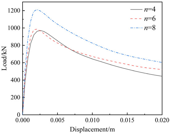
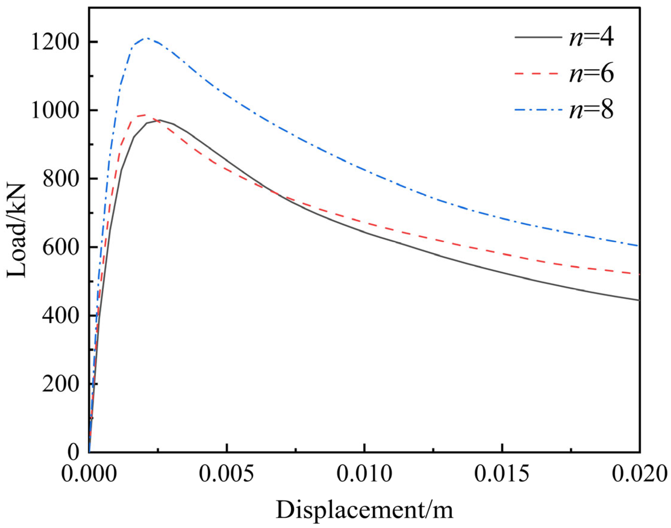
Figure 28 shows the influence of different numbers of bolts on the bending load–displacement curve of the precast concrete cable trench joint numerical models. As observed in the figure, with the increase in the number of bolts, the peak of the load–displacement curve continuously increases. When the number of bolts reaches 8, the peak load of the specimen shows a precipitous rise from 992.34 kN to 1212.3 kN. Both the ascending branch and the peak of the specimen continuously increase, and the peak gradually shifts leftward. This indicates that increasing the number of bolts can significantly enhance the specimen’s resistance to deformation.
Figure 28.
Load–displacement curves of different bolt numbers.
Figure 29 shows the influence of different numbers of bolts on the flexural performance of bolted connection joints in precast concrete cable trench structures. As observed in the figure, with the increase in the number of bolts, the ultimate bearing capacity and flexural rigidity of the specimens both show a linear growth trend, while the peak deflection decreases linearly. Specifically, the ultimate bearing capacity increases from 971.29 kN to 1212.3 kN; the flexural rigidity increases with the number of bolts, rising rapidly from the initial 7.13 × 10⁵ kN·m2 to 9.81 × 10⁵ kN·m2; the ductility reaches a low point when the number of bolts is 6, which may be due to relatively concentrated bolt stress and the failure to form an effective secondary load path, resulting in insufficient deformation capacity in the later stage. This indicates that increasing the number of bolts can significantly enhance the overall flexural performance of the specimens, and the number of bolts has a notable influence on the mechanical properties of the bolted connection joints in precast concrete cable trench structures.
Figure 29.
Influence of number of bolts on mechanical properties of specimens.
5. Conclusions
This study systematically investigated the mechanical properties and optimal design methods of precast cable trench joints using JFRAC through a combination of experimental and numerical simulation approaches. The main conclusions are as follows:
(1) Compressive strength tests were conducted on concrete with different jute fiber volume content and RCA replacement rate. The test results showed that the addition of jute fiber would reduce the elastic modulus and increase the compressive strength of the concrete, while the increase in the RCA replacement rate would reduce both the elastic modulus and compressive strength of the concrete. To accurately reflect the behavior of JFRAC, a modified CDP model was established, with errors between numerical simulations and experimental data below 5%.
(2) For the cable trench structure, the JFRAC structure exhibits enhancements in ultimate bearing capacity, peak displacement, and ductility by 4.17%, 18.78%, and 14.66%, respectively, compared with the conventional C30 concrete structure, while the flexural rigidity shows a marginal reduction of 1.65%. Furthermore, JFRAC is environmentally and economically superior to C30 concrete, resulting in a reduction of 2.29% in carbon emissions and cost savings of CNY 62.43 per meter of cable trench during the material production process. This results in concurrent economic and environmental benefits, demonstrating that JFRAC holds considerable promise for replacing conventional concrete in cable trench structure applications.
(3) The main influencing factors on the JFRAC precast cable trench joints’ performance are the bolt grade and bolt number by conducting and analyzing the results of a total of 15 numerical models. As the bolt grade increases from 8.8 to 10.9, its influence diminishes progressively, whereas an increase in the number of bolts leads to a nearly linear enhancement in the load-bearing capacity of the member. In addition, bolt diameter and bolt preload also slightly affect the performance of the JFRAC precast cable trench joints. Among these parameters, an increase in bolt diameter from 28 mm to 34 mm results in a progressive enhancement in both the load-bearing capacity and flexural rigidity of the member. In contrast, when the bolt preload exceeds 70 kN, further increases exhibit limited influence on the structural performance of the JFRAC precast cable trench joints.
(4) Beyond the technical optimizations, the application of JFRAC in precast cable trenches contributes significantly to the sustainable development of the construction industry. By promoting the resource utilization of solid waste (recycled aggregates and recycled jute fiber) and reducing carbon emissions during material production, this study aligns with global carbon neutrality goals and provides a feasible technical path for low-carbon transformation in power infrastructure engineering. However, the current research primarily focuses on its short-term mechanical properties, while its long-term sustainability remains unclear. Future work should prioritize the integration of life cycle assessment for JFRAC to promote its reliable application in low-carbon engineering.
Author Contributions
Conceptualization, J.Z. and L.J.; methodology, M.B.; software, X.F.; validation, Y.Z. and J.J.; formal analysis, Y.Z.; investigation, M.B.; resources, W.Z. and K.S.; writing—original draft preparation, X.F.; writing—review and editing, L.J.; supervision, J.Z.; funding acquisition, J.Z. and L.J. All authors have read and agreed to the published version of the manuscript.
Funding
This research was funded by the Commonweal Project of Zhejiang Province, grant number LGG22E090002; the Basic Research Business Fund Youth Project of Zhejiang University of Science and Technology, grant number 2025QN027; the Natural Science Foundation of Zhejiang Province, grant number LQN25E080016; and the General Project of Education of Zhejiang Province, grant number Y202454594; the Joint Fund of Zhejiang Provincial Natural Science Foundation of China, grant number LGEY26E090013.
Institutional Review Board Statement
Not applicable.
Informed Consent Statement
Not applicable.
Data Availability Statement
The raw data supporting the conclusions of this article will be made available by the authors on request.
Conflicts of Interest
Authors Weijun Zhong and Kai Shu were employed by the company Ningbo Electric Power Design Institute Co., Ltd. The remaining authors declare that the research was conducted in the absence of any commercial or financial relationships that could be construed as a potential conflict of interest.
References
- Cui, Y.D.; Bian, R.; Wang, S.H.; Xu, H.; Jiang, S.C. Analysis on structural responses of prefabricated cable tunnels with different joints in uneven subsidence. Ind. Constr. 2021, 51, 64–70. [Google Scholar] [CrossRef]
- Gong, C.; Ding, W.; Mosalam, K.M.; Gunay, S.; Soga, K. Comparison of the structural behavior of reinforced concrete and steel fiber reinforced concrete tunnel segmental joints. Tunn. Undergr. Space Technol. 2017, 68, 38–57. [Google Scholar] [CrossRef] [Scilit]
- Ali, A.H.; Gouda, A.; Mohamed, H.M.; Rabie, M.H.; Benmokrane, B. Nonlinear finite elements modeling and experiments of FRP reinforced concrete piles under shear loads. Structures 2020, 28, 106–119. [Google Scholar] [CrossRef] [Scilit]
- Merli, R.; Preziosi, M.; Acampora, A.; Lucchetti, M.C.; Petrucci, E. Recycled fibers in reinforced concrete: A systematic literature review. J. Clean. Prod. 2020, 248, 119207. [Google Scholar] [CrossRef] [Scilit]
- Sultana, N.; Hossain, S.Z.; Alam, M.S.; Hashish, M.M.A.; Islam, M.S. An experimental investigation and modeling approach of response surface methodology coupled with crow search algorithm for optimizing the properties of jute fiber reinforced concrete. Constr. Build. Mater. 2020, 243, 118216. [Google Scholar] [CrossRef] [Scilit]
- Xu, G.T.; Liu, M.J.; Xiang, Y.; Fu, B. Valorization of macro fibers recycled from decommissioned turbine blades as discrete reinforcement in concrete. J. Clean. Prod. 2022, 379, 134550. [Google Scholar] [CrossRef] [Scilit]
- Asaduzzaman, S.M.; Islam, G.S. Using jute fiber to improve fresh and hardened properties of concrete. J. Nat. Fibers 2023, 20, 2204452. [Google Scholar] [CrossRef] [Scilit]
- Bheel, N.; Tafsirojjaman, T.; Liu, Y.; Awoyera, P.; Kumar, A.; Keerio, M.A. Experimental study on engineering properties of cement concrete reinforced with nylon and jute fibers. Buildings 2021, 11, 454. [Google Scholar] [CrossRef] [Scilit]
- Ferreira, S.R.; Mendes de Andrade, R.G.; Koenders, E.; de Andrade Silva, F.; de Moraes Rego Fairbairn, E.; Toledo Filho, R.D. Pull-out behavior and tensile response of natural fibers under different relative humidity levels. Constr. Build. Mater. 2021, 308, 124823. [Google Scholar] [CrossRef] [Scilit]
- Islam, M.S.; Ahmed, S.J. Influence of jute fiber on concrete properties. Constr. Build. Mater. 2018, 189, 768–776. [Google Scholar] [CrossRef] [Scilit]
- Zakaria, M.; Ahmed, M.; Hoque, M.; Shaid, A. A comparative study of the mechanical properties of jute fiber and yarn reinforced concrete composites. J. Nat. Fibers 2020, 17, 676–687. [Google Scholar] [CrossRef] [Scilit]
- Evangelista, L.; de Brito, J. Mechanical behaviour of concrete made with fine recycled concrete aggregates. Cem. Concr. Compos. 2007, 29, 397–401. [Google Scholar] [CrossRef] [Scilit]
- Rahal, K. Mechanical properties of concrete with recycled coarse aggregate. Build. Environ. 2007, 42, 407–415. [Google Scholar] [CrossRef] [Scilit]
- Ribeiro, M.C.S.; Meira-Castro, A.C.; Silva, F.G.; Santos, J.; Meixedo, J.P.; Fiúza, A.; Dinis, M.L.; Alvim, M.R. Re-use assessment of thermoset composite wastes as aggregate and filler replacement for concrete-polymer composite materials: A case study regarding GFRP pultrusion wastes. Resour. Conserv. Recycl. 2015, 104, 417–426. [Google Scholar] [CrossRef] [Scilit]
- Kurda, R.; De Brito, J.; Silvestre, J.D. Water absorption and electrical resistivity of concrete with recycled concrete aggregates and fly ash. Cem. Concr. Compos. 2019, 95, 169–182. [Google Scholar] [CrossRef] [Scilit]
- Raza, A.; Manalo, A.; Rafique, U.; Alajarmeh, O.S.; Khan, Q.U.Z. Concentrically loaded recycled aggregate geopolymer concrete columns reinforced with GFRP bars and spirals. Compos. Struct. 2021, 268, 113968. [Google Scholar] [CrossRef] [Scilit]
- Zhao, Y.; Zeng, W.; Zhang, H. Properties of recycled aggregate concrete with different water control methods. Constr. Build. Mater. 2017, 152, 539–546. [Google Scholar] [CrossRef] [Scilit]
- El Ouni, M.H.; Raza, A.; Elhadi, K.M.; Azab, M.; Arshad, M.; Matiullah. Parametric investigation of GFRP-RCC jute fibre-reinforced recycled aggregate concrete elements. Structures 2022, 45, 1043–1061. [Google Scholar] [CrossRef] [Scilit]
- Fan, C.C.; Huang, R.; Hwang, H.; Chao, S.J. Properties of concrete incorporating fine recycled aggregates from crushed concrete wastes. Constr. Build. Mater. 2016, 112, 708–715. [Google Scholar] [CrossRef] [Scilit]
- Jamil, K.; Shabbir, F.; Raza, A. Performance evaluation of jute fiber-reinforced recycled aggregate concrete: Strength and durability aspects. Struct. Concr. 2023, 24, 6520–6538. [Google Scholar] [CrossRef] [Scilit]
- Hameed, R.; Tahir, M.; Abbas, S.; Sheikh, H.U.; Kazmi, S.M.S.; Munir, M.J. Mechanical and durability characterization of hybrid recycled aggregate concrete. Materials 2024, 17, 1571. [Google Scholar] [CrossRef] [Scilit] [PubMed]
- Tittarelli, F.; Moriconi, G. Use of GRP industrial by-products in cement based composites. Cem. Concr. Compos. 2010, 32, 219–225. [Google Scholar] [CrossRef] [Scilit]
- Correia, J.R.; Almeida, N.M.; Figueira, J.R. Recycling of FRP composites: Reusing fine GFRP waste in concrete mixtures. J. Clean. Prod. 2011, 19, 1745–1753. [Google Scholar] [CrossRef] [Scilit]
- Fonseca, C.S.; Silva, M.F.; Mendes, R.F.; Hein, P.R.G.; Zangiacomo, A.L.; Savastano, H., Jr.; Tonoli, G.H.D. Jute fibers and micro/nanofibrils as reinforcement in extruded fiber-cement composites. Constr. Build. Mater. 2019, 211, 517–527. [Google Scholar] [CrossRef] [Scilit]
- Xu, Y.; Cui, T.; Wu, B.; Wang, Z.; Song, Y. Dynamic mode I fracture characteristics of jute fiber-reinforced rubber mortar. Eng. Fract. Mech. 2023, 292, 109649. [Google Scholar] [CrossRef] [Scilit]
- Xu, S.; Liu, J.; Xu, Q. Parametric investigation of oblique incidence angle effects in Near-Fault P waves on dynamic response of concrete dam. Appl. Sci. 2025, 15, 6853. [Google Scholar] [CrossRef] [Scilit]
- Peter, G.; Dimitrios, X.; Ulrika, N.; Rasmus, R.; Kent, G. CDPM2: A damage-plasticity approach to modelling the failure of concrete. Int. J. Solids Struct. 2013, 50, 3805–3816. [Google Scholar] [CrossRef] [Scilit]
- Ding, F.; Wu, X.; Xiang, P.; Yu, Z. New damage ratio strength criterion for concrete and lightweight aggregate concrete. ACI Struct. J. 2021, 118, 165–178. [Google Scholar] [CrossRef] [Scilit]
- Brandt, A.M. Fibre reinforced cement-based (FRC) composites after over 40 years of development in building and civil engineering. Compos. Struct. 2008, 86, 3–9. [Google Scholar] [CrossRef] [Scilit]
- Hasan, R.; Sobuz, M.H.R.; Akid, A.S.M.; Awall, R.; Houda, M.; Saha, A.; Meraz, M.; Islam, S.; Sutan, N.M. Eco-friendly self-consolidating concrete production with reinforcing jute fiber. J. Build. Eng. 2023, 63, 105519. [Google Scholar] [CrossRef] [Scilit]
- Huang, B.T.; Zhu, J.X.; Weng, K.F. Ultra-high-strength engineered/strain-hardening cementitious composites (ECC/SHCC): Material design and effect of fiber hybridization. Cem. Concr. Compos. 2022, 129, 104464. [Google Scholar] [CrossRef] [Scilit]
- Peng, K.D.; Huang, B.T.; Xu, L.Y.; Hu, R.L.; Dai, J.G. Flexural strengthening of reinforced concrete beams using geopolymer-bonded small-diameter CFRP bars. Eng. Struct. 2022, 256, 113992. [Google Scholar] [CrossRef] [Scilit]
- Xi, H.; Zhang, Z.; Zhuo, F.; Hou, L.; Zhang, H.; Zhang, W.; Ji, X.; Liu, K.; Shen, Y.; Lao, J. High-strength high-ductility Engineered/Strain-Hardening Geopolymer Composites (EGC/SHGC) incorporating dredged river sand. Case Stud. Constr. Mater. 2025, 22, 2214–5095. [Google Scholar] [CrossRef] [Scilit]
- Tahir, M.; Karam, M.S.; Hassam, M.; Umer, M.; Hameed, R. Numerical evaluation of axial compressive behavior of hollow concrete columns reinforced with GFRP bars and spirals. Struct. Concr. 2024, 25, 566–582. [Google Scholar] [CrossRef] [Scilit]
- Ding, W.; Chen, X.; Jin, Y.L.; Qiao, Y.F. Flexural behavior of segmental joint containing double rows of bolts: Experiment and simulation. Tunn. Undergr. Space Technol. 2021, 112, 103940. [Google Scholar] [CrossRef] [Scilit]
- Mao, Y.; Yang, Z.; Wang, G.; Chen, J.; Yan, J.; Wang, Z. A study on the mechanical behavior of umbilical cables under impact loads using experimental and numerical methods. Mar. Struct. 2025, 99, 103700. [Google Scholar] [CrossRef] [Scilit]
- Tang, R.; Ding, W.; Qian, Y. Rigidity Calculation Model for Transverse Joint of Prefabricated Utility Tunnel Based on Physical Guidance. Russ. Phys. J. 2021, 64, 436–449. [Google Scholar] [CrossRef] [Scilit]
- Wang, F.; Huang, H.; Soga, K.; Li, Z. 3D modelling of concrete tunnel segmental joints and the development of a new bolt-spring model. Tunn. Undergr. Space Technol. 2021, 110, 103835. [Google Scholar] [CrossRef] [Scilit]
- Wang, Y.; Zhang, Y.; Ji, X. Mechanical Performance of Reinforced Sleeve Connection of Prefabricated Concrete Structure and Optimization Design of Its Joints. Eur. J. Comput. Mech. 2025, 34, 1–28. [Google Scholar] [CrossRef] [Scilit]
- Huang, Z.; Bai, H.; Ma, S.; Zhang, J.; Chen, Y.; Li, H. Large-scale testing of the mortise and tenon joint performance of the tunnel lining of prefabricated frame tunnels. Tunn. Undergr. Space Technol. 2023, 131, 104828. [Google Scholar] [CrossRef] [Scilit]
- Li, X.; Yan, Z.; Wang, Z.; Zhu, H. A progressive model to simulate the full mechanical behavior of concrete segmental lining longitudinal joints. Eng. Struct. 2015, 93, 97–113. [Google Scholar] [CrossRef] [Scilit]
- Wang, L.; Chen, X.; Su, D.; Liu, S.; Liu, X.; Jiang, S.; Gao, H.; Yang, W. Mechanical performance of a prefabricated subway station structure constructed by twin closely-spaced rectangular pipe-jacking boxes. Tunn. Undergr. Space Technol. 2023, 135, 105062. [Google Scholar] [CrossRef] [Scilit]
- ASTM C39/C39M-16; Standard Test Method for Compressive Strength of Cylindrical Concrete Specimens. ASTM International: West Conshohocken, PA, USA, 2016. Available online: https://engineering.tiu.edu.iq/civil/wp-content/uploads/2021/11/C39-C39M.pdf (accessed on 15 August 2025).
- GB 50010-2010; Code for Design of Concrete Structures. China Planning Press: Beijing, China, 2015. Available online: https://www.doc88.com/p-70580404773473.html (accessed on 15 August 2025). (In Chinese)
- Wang, L.; Chen, X.; Zhang, Y. Long-age contraction and basic mechanics performance study of regenerated aggregate concrete. Concrete 2013, 7, 23–25. [Google Scholar] [CrossRef]
- Tuo, Z.X.; Hu, J.P.; Yu, L.D. Carbon emission research of long-life pavement structures based on cement and asphalt. West. China Commun. Sci. Technol. 2025, 8, 14–18. [Google Scholar] [CrossRef]
- Zhu, J.F.; Xia, Y.N.; Ju, L.Y.; Yang, H.; Wang, Z.Q.; Jin, J.Y.; Zou, Y.C.; Liao, Y.C. Physico-mechanical performance and micro–mechanism analysis on urban sludge modified with a low carbon binder. Acta Geotech. 2025, 20, 5585–5601. [Google Scholar] [CrossRef] [Scilit]
- Zhu, J.F.; Zheng, Q.Q.; Tao, Y.L.; Ju, L.Y.; Yang, H.; Gong, X.N.; Pan, B.J.; Wang, Z.Q. The curing mechanism and empirical model for the marine organic soft clay stabilized with calcium carbide residue and silica fume under the optimal ratio. Acta Geotech. 2024, 20, 683–706. [Google Scholar] [CrossRef] [Scilit]
- Xiao, J.Z.; Pan, Y.B.; Wang, C.H.; Fang, H.B.; Liang, R.M.; Ge, X.Y.; Wang, P.J.; Guan, X.S.; Xu, H.L.; Ning, J.Q.; et al. Deformation behavior and low-carbon assessment of large-span beam with fully recycled concrete. Strateg. Study CAE 2025, 27, 129–141. [Google Scholar] [CrossRef] [Scilit]
- Singh, A.K.; Kumar, M.; Mitra, S. Carbon footprint and energy use in jute and allied fibre production. Indian J. Agric. Sci. 2018, 88, 1305–1311. [Google Scholar] [CrossRef] [Scilit]





Disclaimer/Publisher’s Note: The statements, opinions and data contained in all publications are solely those of the individual author(s) and contributor(s) and not of MDPI and/or the editor(s). MDPI and/or the editor(s) disclaim responsibility for any injury to people or property resulting from any ideas, methods, instructions or products referred to in the content. |
© 2026 by the authors. Licensee MDPI, Basel, Switzerland. This article is an open access article distributed under the terms and conditions of the Creative Commons Attribution (CC BY) license.