


Abstract
The transition toward sustainable energy systems necessitates innovative solutions that reduce greenhouse gas emissions while improving fuel efficiency in existing combustion technologies. Hydrogen has emerged as a promising clean energy carrier; however, its widespread deployment is limited by challenges associated with large-scale transportation and storage. This study investigates a practical alternative in which hydrogen-rich syngas produced via steam methane reforming (SMR) is directly integrated into the diesel engine intake, thereby eliminating the need for fuel transport, storage, and separation while supporting a more sustainable fuel pathway. A validated computational fluid dynamics (CFD) model was developed to examine the effects of varying SMR gas mixture ratios (0–20%) on engine combustion, performance, and emissions. The findings reveal that increasing the SMR fraction enhances in-cylinder pressure by up to 15.7%, heat release rate by 100%, and engine power output by 102.5% compared to conventional diesel operation. Additionally, under SMR20 conditions, CO2 emissions are reduced by approximately 12%, demonstrating the potential contribution of this approach to decarbonization and climate mitigation efforts. However, the rise in in-cylinder temperatures was found to increase NOx formation, indicating the necessity for complementary emission control strategies. Overall, the results suggest that direct SMR syngas integration offers a promising pathway to improve the environmental and performance characteristics of conventional diesel engines while supporting cleaner energy transitions.
1. Introduction
The depletion of fossil fuel resources and the environmental impacts of their combustion, particularly greenhouse gas (GHG) and nitrogen oxide (NOx) emissions, have accelerated global efforts toward sustainable energy systems. Internal combustion engines (ICEs), despite their efficiency and widespread role in transportation and power generation, remain heavily dependent on fossil fuels and thus contribute significantly to anthropogenic emissions [1,2]. Meeting international climate targets, including the European Union Green Deal (2030) and the net-zero emission targets for 2050 set by the United Nations Framework Convention on Climate Change (UNFCCC), requires a shift toward low-carbon or carbon-free fuels capable of improving combustion efficiency while reducing harmful emissions [3,4].
As an energy vector, hydrogen bridges the gap between primary energy sources and end uses by enabling the transport of energy produced by other systems [5].
Hydrogen has emerged as a particularly promising alternative due to its high flame speed, wide flammability range, low ignition energy, and carbon-free combustion products [6,7,8]. Its use in ICEs has been shown to enhance thermal efficiency and substantially reduce CO2 emissions [9,10]. However, large-scale application is limited by storage and transportation challenges. Conventional storage methods such as compressed gas and cryogenic tanks suffer from low volumetric energy density, high costs, and safety risks [11]. These constraints hinder the practical deployment of hydrogen in the transport and energy sectors, despite its environmental benefits.
Hydrogen can be produced through various processes using different sources and methods. Hydrogen generally produces water as a primary byproduct in combustion processes, resulting in minimal environmental impact and near-zero greenhouse gas (GHG) emissions. This characteristic highlights its potential as a clean and sustainable energy source [12]. There are various methods for hydrogen production, mainly thermal, electrochemical, and biological. Among production technologies, steam methane reforming (SMR) is the dominant method for global hydrogen supply [13,14]. According to a recent study, steam methane reforming is expected to produce 62% of the hydrogen worldwide in 2021 [15]. Recent investigations suggest that the SMR process is an effective method for hydrogen production, capable of supplying a substantial portion of the required hydrogen [16]. Hydrogen production in SMR systems has been investigated from various perspectives [17], with a focus on optimized reactor design [18]. There are significant limitations on the utilization of hydrogen in energy systems after its production. In particular, storage and transportation from production facilities to end-use locations remain major barriers to the large-scale utilization of hydrogen energy [19]. Compressed hydrogen gas is usually stored in cylinder tanks at 200 bar. However, the energy density is inadequate at this pressure and storage vessels with higher pressures are either unsafe and cost-prohibitive [20].
Recent studies have focused on optimizing hydrogen combustion and SMR through advanced catalyst design, electrified reactors and integration with carbon capture technologies. Barokh et al. (2024) investigated the effect of parameters such as porosity, pore density, pore distribution, flow direction, inlet velocity and temperature on hydrogen production rates of the catalyst used in a steam methane reformer reactor [20]. Kumar et al. (2024) employed numerical methods to develop and validate the chemical reaction mechanisms for steam methane reforming (SMR) and steam biogas reforming (SBR) processes [21]. Devasahayam et al. (2025) [22] focused on a thorough sustainability evaluation of dry reforming of methane (DRM), with carbon intensity and syngas energy recovery (%) serving as the main performance metrics. The authors employed simulations to quantify uncertainty and determine robust operating conditions. They also conducted techno-economic analyses to compare SMR and electrolysis [22]. Amini et al. (2023) analyzed the transport phenomena in a turbulent fluid flow with chemical reactions using a three-dimensional CFD simulation [23]. The realizable k-ɛ turbulence model and the discrete ordinates radiation model were applied to simulate the kinetic mechanism of the SMR process and hydrogen/methane combustion. Mehanovic et al. (2023) presented a detailed analysis demonstrating that electrified steam methane reforming (eSMR) is feasible and offers highly favorable economics using conventional reformer tubes, catalysts, and high-temperature heating equipment [24]. Sayer et al. (2024) examined four major hydrogen production chains and two modes of transportation from North Africa to Europe, evaluating the costs and environmental impacts of each [25]. Qiao et al. (2024) developed a new integrated system combining steam methane reforming, hydrogen liquefaction, and waste heat recovery based on LNG cold energy [26]. In addition to hydrogen production methods, the combustion of hydrogen has been extensively studied in the literature in recent years. Sekar et al. (2024) investigated the effect of hydrogen mass fraction on the performance of gas burners fueled with methane–hydrogen–air mixtures [27]. Qiang et al. (2024) investigated the effects of single and split injection techniques on the combustion and emissions of turbulent jet ignition (TJI) hydrogen-powered engines at low loads [28]. Bayramoğlu and Yılmaz (2021) conducted a computational analysis of hydrogen-diesel combustion in internal combustion engines using direct injection [29]. Sattarzadeh et al. (2022) [30] aimed to analyze the performance of a heavy-duty diesel engine under RCCI combustion fueled by a mixture of diesel fuel and natural gas, with varying syngas compositions. The simulation results show that increasing the CO/H2 volumetric ratio alone can increase engine output power by up to 27.7% [30]. Habib et al. (2024) investigated and compared hydrogen applications in engines, focusing on the CO2-free enrichment of ammonia with hydrogen in terms of production methods and combustion performance [6]. Ağbulut et al. (2025) [8] investigated the utilization of exhaust heat from an onboard diesel engine to produce hydrogen-rich syngas through methanol steam reforming (MSR). The study aimed to maximize the hydrogen content in syngas by optimizing operational parameters using different algorithms [8]. Piano et al. (2025) investigated the optimal injection and combustion stages for a hydrogen-fueled heavy-duty direct-injection engine [31]. The results show the effect of injection ignition on brake efficiency, combustion variability, and the formation of NOx emissions. Kandasamy et al. (2025) [32] synthesized hydrogen-rich syngas using waste groundnut shells and waste milk cartons through the co-pyrolysis method. The authors increased the hydrogen content of high-quality syngas and evaluated its performance as a fuel in a diesel engine. The engine testing revealed that brake thermal efficiency (BTE) was 32.2% with hydrogen-enriched syngas and 30.98% with non-hydrogen-enriched syngas [32].
To address the literature gap, the present study proposes a novel system in which hydrogen-rich syngas produced by an SMR reactor is directly introduced into a diesel engine intake without undergoing separation, storage, or transportation. A validated computational fluid dynamics (CFD) model was employed to investigate the impact of varying SMR syngas fractions (0–20%) on in-cylinder combustion, performance, and emissions. Unlike prior works, this integrated approach captures both production and utilization dynamics, providing new insights into efficiency gains, CO2 reduction, and NOx formation. The outcomes contribute to the broader discourse on hydrogen’s role in sustainable energy transitions and highlight its potential to support global net-zero strategies through the direct coupling of production and utilization within existing ICE infrastructure. The novelty of the present study lies in the quantitative numerical evaluation of syngas-assisted diesel combustion using literature-based reformer data as boundary conditions, rather than in the qualitative identification of syngas effects.
2. Materials and Methods
2.1. System Description
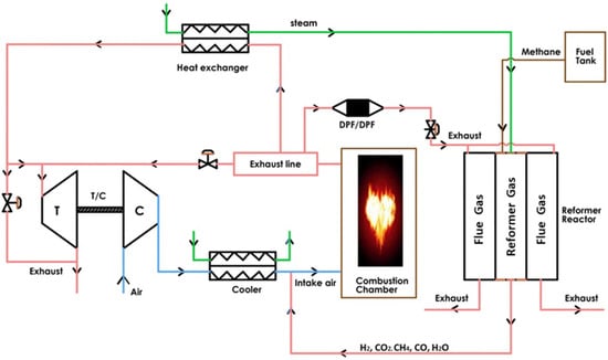
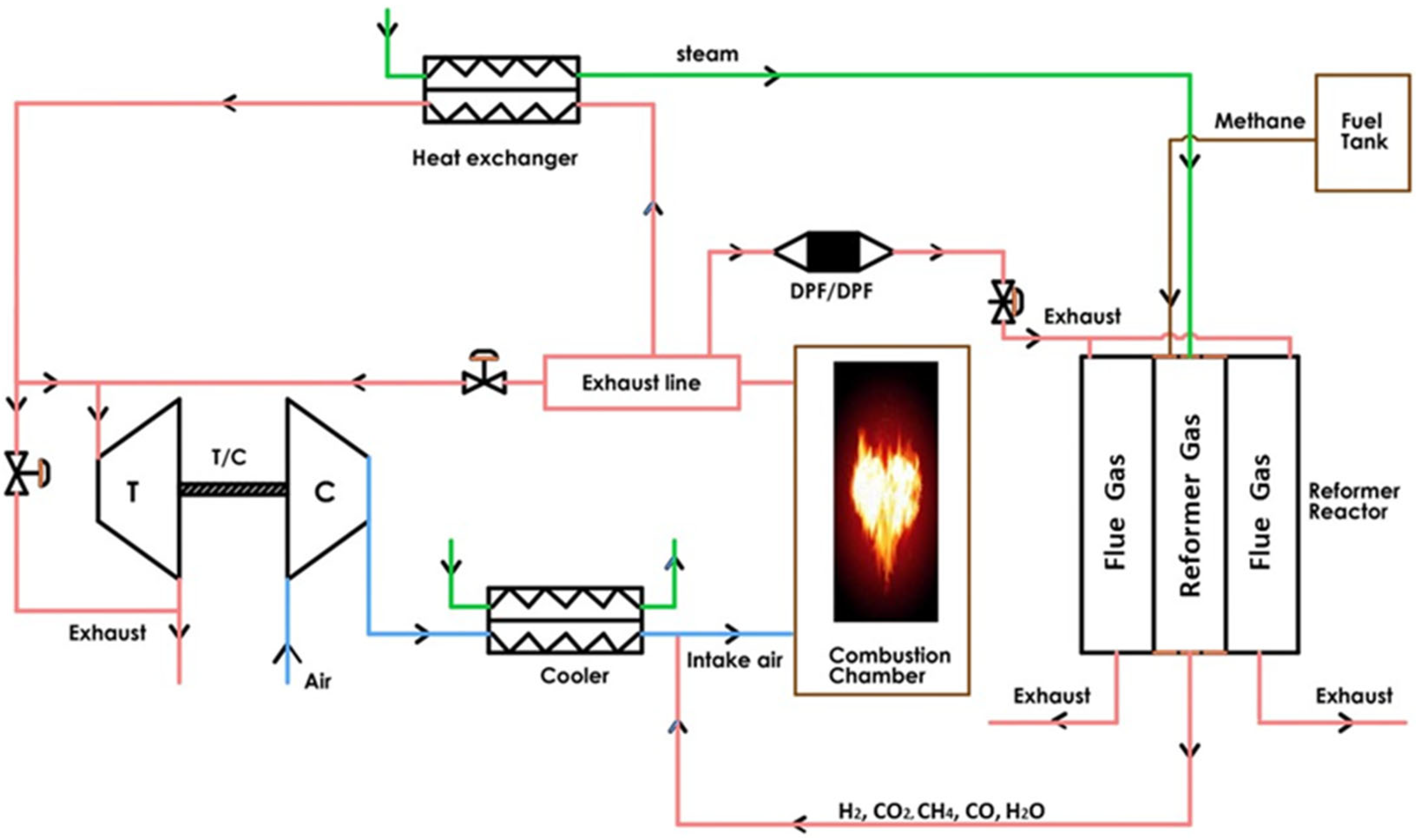
The effects on engine performance and emissions were evaluated numerically by incorporating gases from steam methane reformer (SMR) reactions at varying rates, along with air from the intake manifold. Steam methane reformer reactors are utilized in diesel engines to recover waste heat from the flue gas generated during the combustion process. They primarily convert methane–steam mixtures into hydrogen fuel by using waste heat. In SMR reactors, CO2 is produced alongside hydrogen. The obtained hydrogen and CO2 are sent from the intake manifold to the diesel engine. Figure 1 shows the diagram of the diesel engine and steam methane reformer system.
Figure 1.
Schematic of the proposed system.
2.2. Steam Methane Reformer
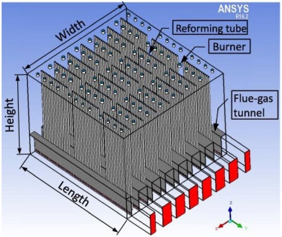
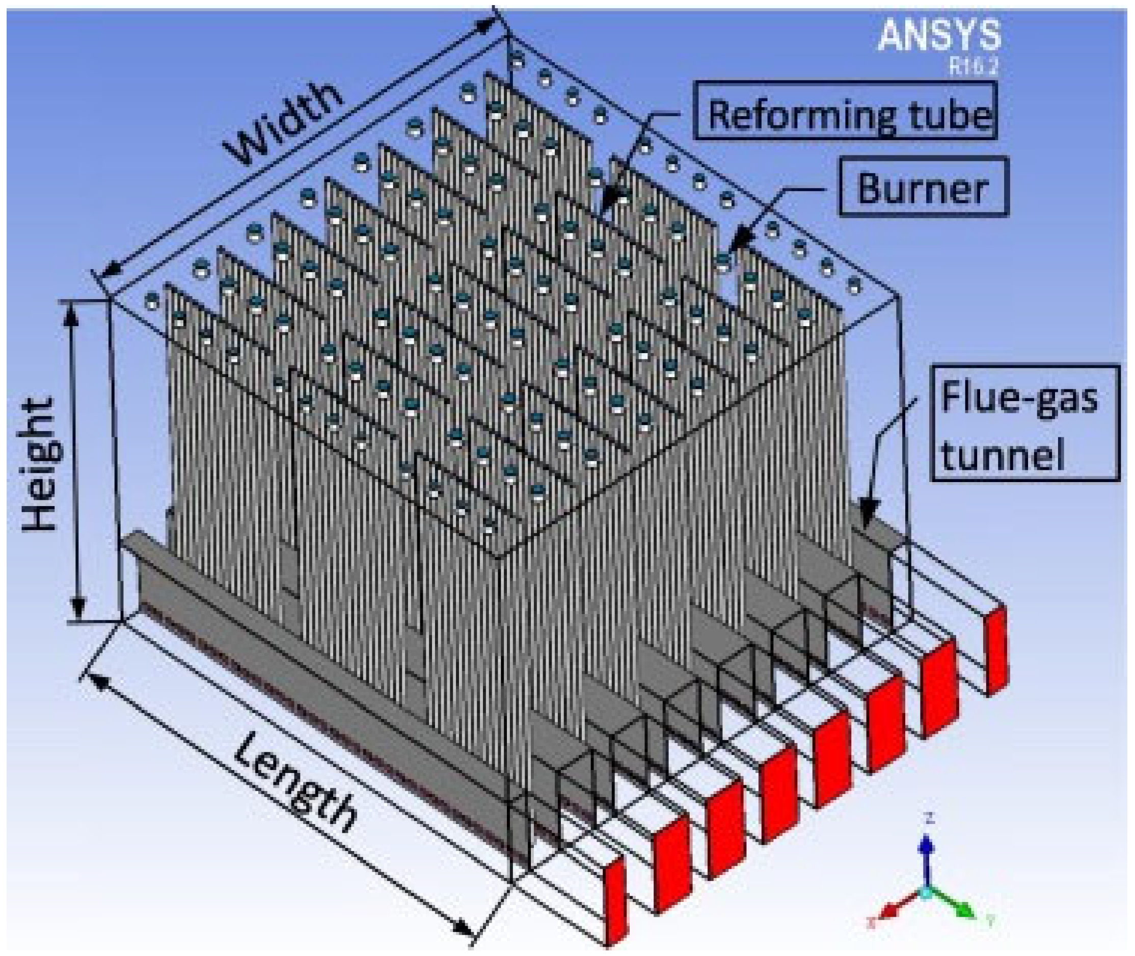
SMR converts steam and methane into a mixture of carbon monoxide (CO), hydrogen (H2), carbon dioxide (CO2), and remaining unreacted components. The catalyst employed in the reformer influences the reaction efficiency and product yield [33]. Hydrogen production data were obtained from numerical studies reported in the literature [34,35]. The data presented in this subsection are adopted from the literature and are used solely to define the boundary conditions of the numerical engine model; no experimental or numerical results are inferred from these data. The steam methane reformer system, whose experimental and numerical models were utilized in an industrial-scale, top-fired, co-current reformer designed by Selas Fluid Processing Corporation, served as the source of hydrogen in this study. This model was selected because it has been widely studied in the literature. The primary purpose of this study is to evaluate the effects of integrating a reformer with a diesel engine on emissions and engine performance. The hydrogen production process from SMR reactions is illustrated in Figure 2.
Figure 2.
Schematic of an industrial-scale, top-fired, co-current reformer.
The reformer dimensions are approximately 16 m in width, 16 m in length, and 13 m in height. The reformer consists of seven rows of forty-eight reforming tubes, each with an exterior diameter of 14.6 cm, an interior diameter of 12.6 cm, and an exposed length of 12.5 m. Under optimal operating conditions, the surroundings around all reforming tubes of the SMR furnace unit are remarkably similar. Therefore, it is required to model only a single reforming tube to define the conditions in all 336 reforming tubes [35]. Hydrogen and synthesis gas are formed through chemical reactions that occur during the steam reforming of methane [21]. In SMR reactions, two of the three reactions are reforming reactions, while the third is a water gas shift reaction. Equations (1) and (2) show the reformer reactions. The water gas shift reaction is shown in Equation (3). Reformer reactions are endothermic, and the WGS reaction is exothermic [36].
Table 1 shows the area-weighted average mole fractions of the products at the outlet of the steam methane reformer. The results were obtained based on experimental laboratory data and CFD model validation [34,35]. The study was conducted under the assumption of a constant heat source and constant flow conditions, and therefore, the ratio of the reformer gases formed was also assumed to remain constant.
Table 1.
SMR reactor outlet specifications.
In the study, the mole fraction of H2O produced by the steam methane reformer was approximately 34%. For the operating boundary conditions, the gas mixture listed in Table 1 was blended with intake air at 5%, 10%, 15%, and 20% and supplied to the diesel engine. The Results and Discussion section evaluates the emission and performance parameters of these combustion gases. Within the scope of the study, only the effects of the gases on combustion and performance parameters were examined, while effects such as corrosion were disregarded.
2.3. Combustion Model
Numerical modeling studies were conducted using ANSYS-FORTÉ software (17.2 version). Its calculations are based on three conservation equations: energy, momentum, and mass conservation [37].
This study uses an upgraded single-cylinder heavy-duty diesel engine from Caterpillar’s 3400 series. Numerical model setup information from previous studies was employed [38,39]. Engine specifications are presented in Table 2.
Table 2.
Specifications of the diesel engine.
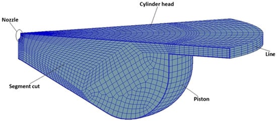
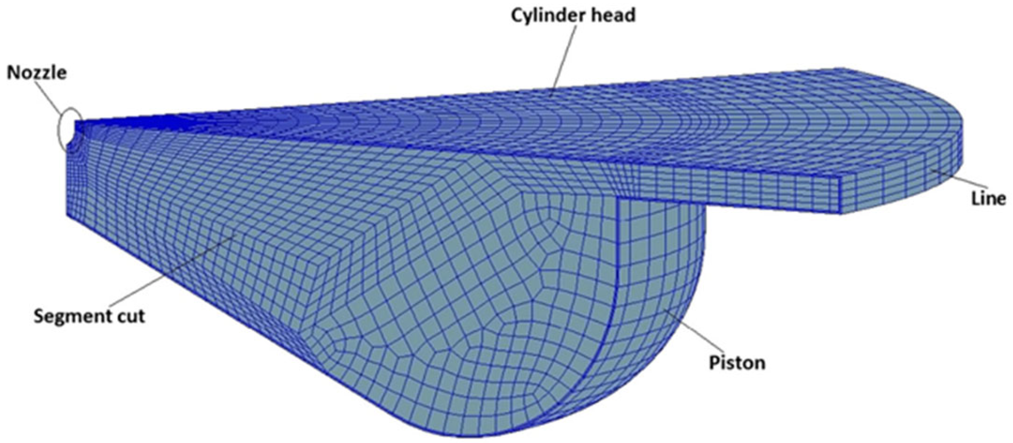
Numerical analyses were conducted at 910 rpm engine speed and 25% engine load. The diesel engine combustion analysis was performed for the crank angle time from intake valve closing (IVC) to exhaust valve opening (EVO). For engine simulation, the gas mixture at the SMR reactor outlet defines the combustion chamber temperature, as well as the pressure and syngas composition at intake valve closing (IVC). Chemical processes and thermodynamic properties should be established to determine combustion products and diesel engine performance. The N-tetradecane reduction mechanism developed by the University of Wisconsin Engine Research Center (ERC) was employed. The reduction process includes 35 species and 76 reactions [40]. Tetradecane (C14H30) diesel fuel was chosen to study its atomization, vaporization, and air-mixing properties. Fuel spray dynamics play a critical role in regulating the combustion process in diesel engines. Selecting a suitable spray model enables accurate modeling of the combustion process. The Kelvin-Helmholtz Rayleigh-Taylor (KH-RT) and gas-jet model spray breakup models were employed in the analysis [41]. In ICEs, the fuel-air mixture forms at high Reynolds numbers due to the swirling geometry of the combustion chamber. The numerical investigations used the k-ε re-normalization group (RNG) turbulence model, which depicts this behavior. The k-ε RNG turbulence model, expressed in Reynolds-averaged Navier-Stokes equations (RANS), is widely utilized in numerical investigations of diesel engines [42]. The computational model and mesh structure of the numerical study are presented in Figure 3. The computational model mainly consists of the diesel engine cylinder head, nozzle, segment cut, line, and piston boundary condition characteristics. In addition, the computational mesh is structurally composed of 505k structural meshes. As shown in Figure 3, the numerical model represents a 60-degree sector geometry, based on the number of nozzles on the injector [43].
Figure 3.
Computational model.
2.4. Boundary Conditions
The molar mixing ratios of the gases obtained in the reformer reactor are presented in Table 3. Reformer outlet gases are supplied to the combustion, blended with 5%, 10%, 15%, and 20% intake air by volume. The composition of the intake air–reformer gas mixture is provided in Table 3.
Table 3.
Mole fraction of intake air.
The Chemkin solver, employed for combustion modeling, provides solutions for fundamental gas-phase chemical kinetics. The combustion model enables the determination of thermodynamic parameters, equations of state and chemical production rates [38]. Table 4 presents the initial and boundary conditions for the combustion mechanism and geometry.
Table 4.
Boundary and initial conditions.
Although constant heat flux and mass-flow boundary conditions are commonly employed in cycle-resolved engine CFD simulations using Ansys Forte, the variability of SMR-derived syngas composition was incorporated in the revised model to reflect realistic engine intake conditions better. Additionally, the potential high-temperature corrosion effects of unseparated syngas components (CO, CO2, H2O) on metal surfaces were acknowledged as a significant limitation, since such degradation requires reactive diffusion and material-interaction modeling, which is beyond the scope of the present thermal–fluid CFD framework.
2.5. Model Validation
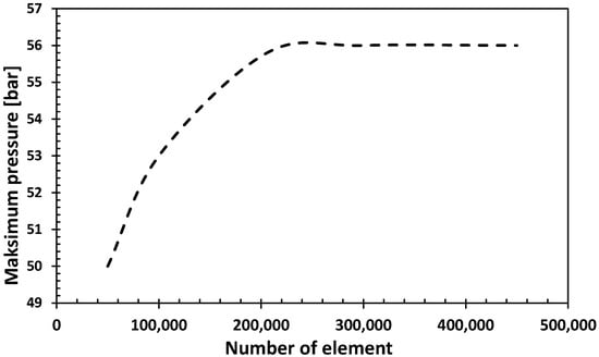
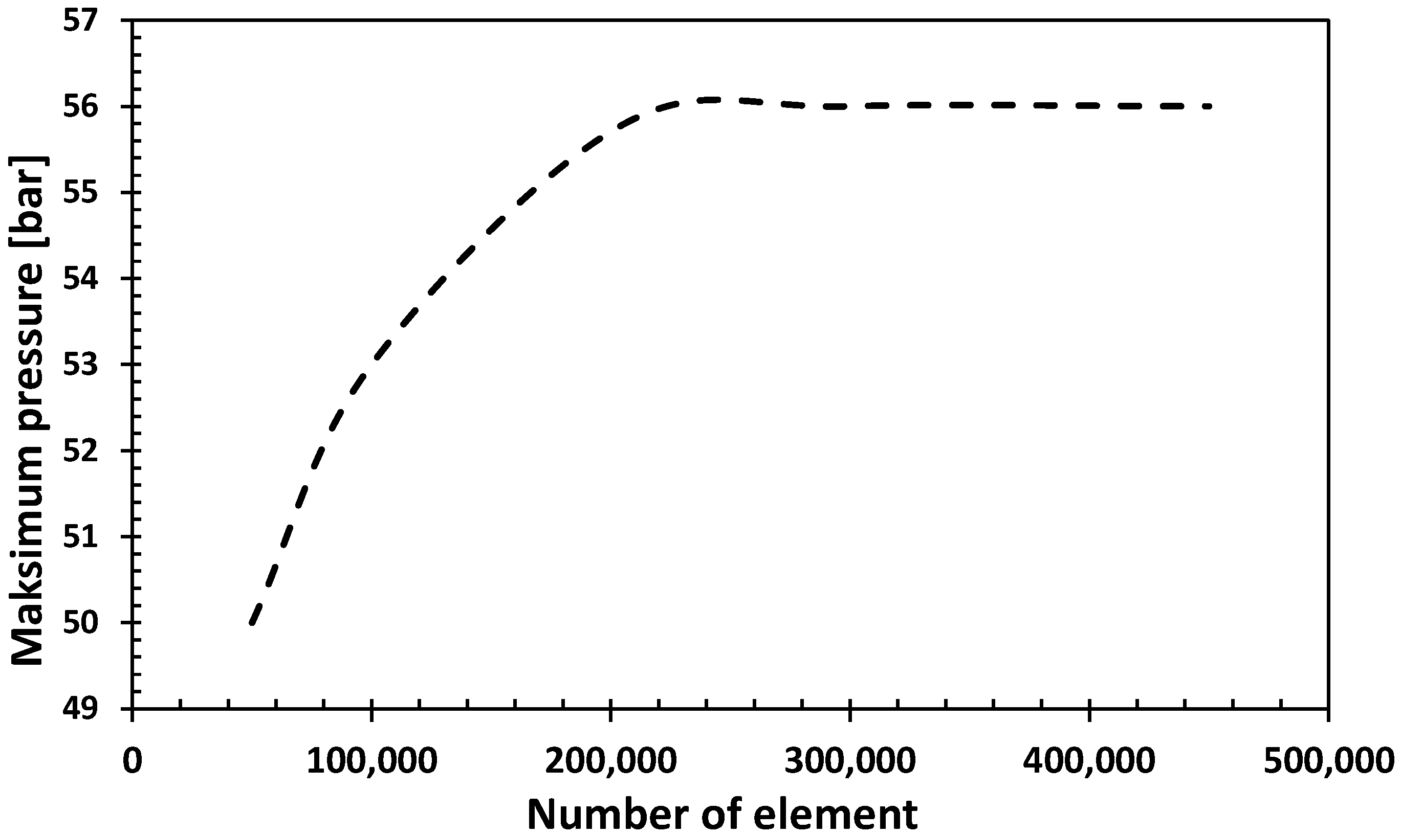
In computational fluid dynamics calculations, the number and structure of meshes are essential parameters for the accuracy of the analyses. In the study, combustion models were created with five different mesh counts. Figure 4 shows the effect of varying mesh numbers on the maximum combustion pressure. The results indicate that combustion pressure remains unchanged for element numbers above 200k. For computational efficiency, the study was conducted with an element count of approximately 205k.
Figure 4.
Analysis of mesh independence.
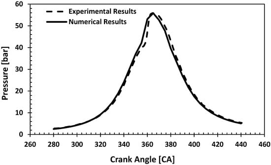
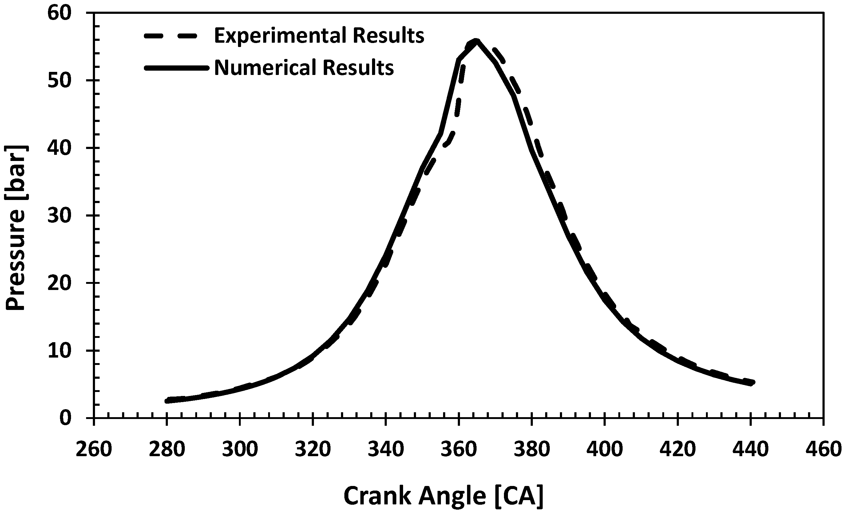
The numerical combustion analyses were compared with experimental data from the literature [38]. The numerical and experimental results were evaluated based on the obtained pressure values. The results of the validation study are presented in Figure 5. CFD simulation results are consistent with experimental results. The validation study, based on pressure values, is directly related to data obtained from the diesel engine, such as energy and average indicated pressure. Therefore, comparing the experimental and numerical pressure values to validate the numerical study is crucial.
Figure 5.
Experimental [38] and computational comparison of in-cylinder pressure.
In the present study, model validation has been performed using experimentally measured in-cylinder pressure and apparent heat release. At the same time, NOx emissions are predicted using an n-tetradecane-based chemical mechanism combined with the extended Zeldovich model. It should be noted that uncertainties in the detailed kinetic mechanism (e.g., ±10% variations in selected rate constants) may affect the absolute magnitude of the computed NOx levels through their influence on flame temperature and radical pool formation. However, the relative trends between the different fueling cases and operating conditions remain robust, because all simulations are performed with a consistent chemical and numerical framework.
3. Results and Discussion
In the study, steam and methane are fed into the reformer reactor, producing gases such as H2, CO2, and CO. Due to challenges associated with hydrogen storage, this gas mixture is not separated through a membrane; instead, it is delivered directly to the combustion chamber along with intake air from the diesel engine manifold. Reformer gases are supplied to the combustion chamber with air at 5%, 10%, 15% and 20% by volume. All performance and emission trends discussed in this section are obtained exclusively from the present CFD simulations; experimental results from the literature are cited only for comparison and context.
3.1. Engine Performance Parameters
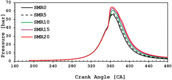
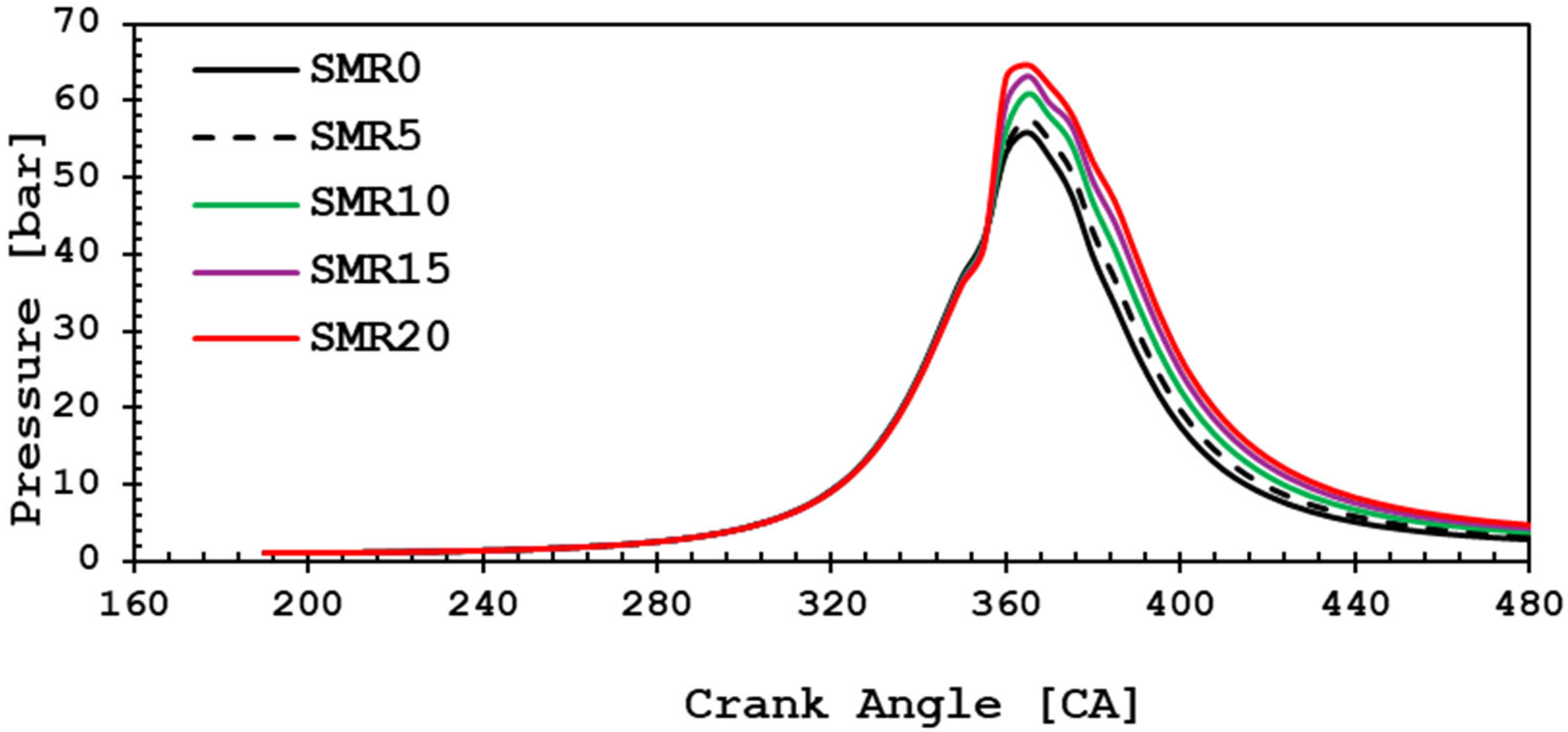
One of the most critical parameters in engine performance is combustion chamber pressure. The cylinder pressure indicates the ability of the fuel to form a homogeneous mixture with atmospheric air and SMR products and to burn efficiently. The effect of reformer gases injected into the intake air at different rates on the combustion chamber pressure is shown in Figure 6. The findings show that the combustion chamber pressure increases with increasing amounts of reformer gases. The maximum pressures for SMR0, SMR5, SMR10, SMR15 and SMR20 were 55.8 bar, 57.6 bar, 60.9 bar, 63.2 bar and 64.7 bar, respectively. The start of combustion in the process was observed to be at a value of approximately 355 CA. Therefore, the ignition delay for the numerical study was determined to be approximately 15 CA and 20 CA. The ignition delay is approximately the same for all SMR rates. The maximum pressure was the same for all parametric studies and was obtained at approximately 365 CA. Additionally, the amount of fuel injected by the injector also significantly affects the variation in combustion pressure. In the study, the fuel injection follows a parabolic profile, which affects the peak pressure. Hydrogen addition from the Steam Methane Reforming (SMR) reactor increases the combustion pressure. A statistical comparison of the combustion chamber pressure reveals that the maximum pressure increases by approximately 3.2%, 9.4%, 13.3%, and 15.9% for SMR5, SMR10, SMR15, and SMR20 hydrogen additions, respectively, compared to the SMR0 case. The increase in combustion pressure directly affects power in diesel engines and enhances engine performance at approximately the same rate. Additionally, studies have shown that hydrogen addition enhances engine combustion pressure and performance [44,45].
Figure 6.
In-cylinder pressure variation for different SMR syngas fractions.
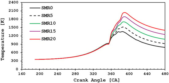
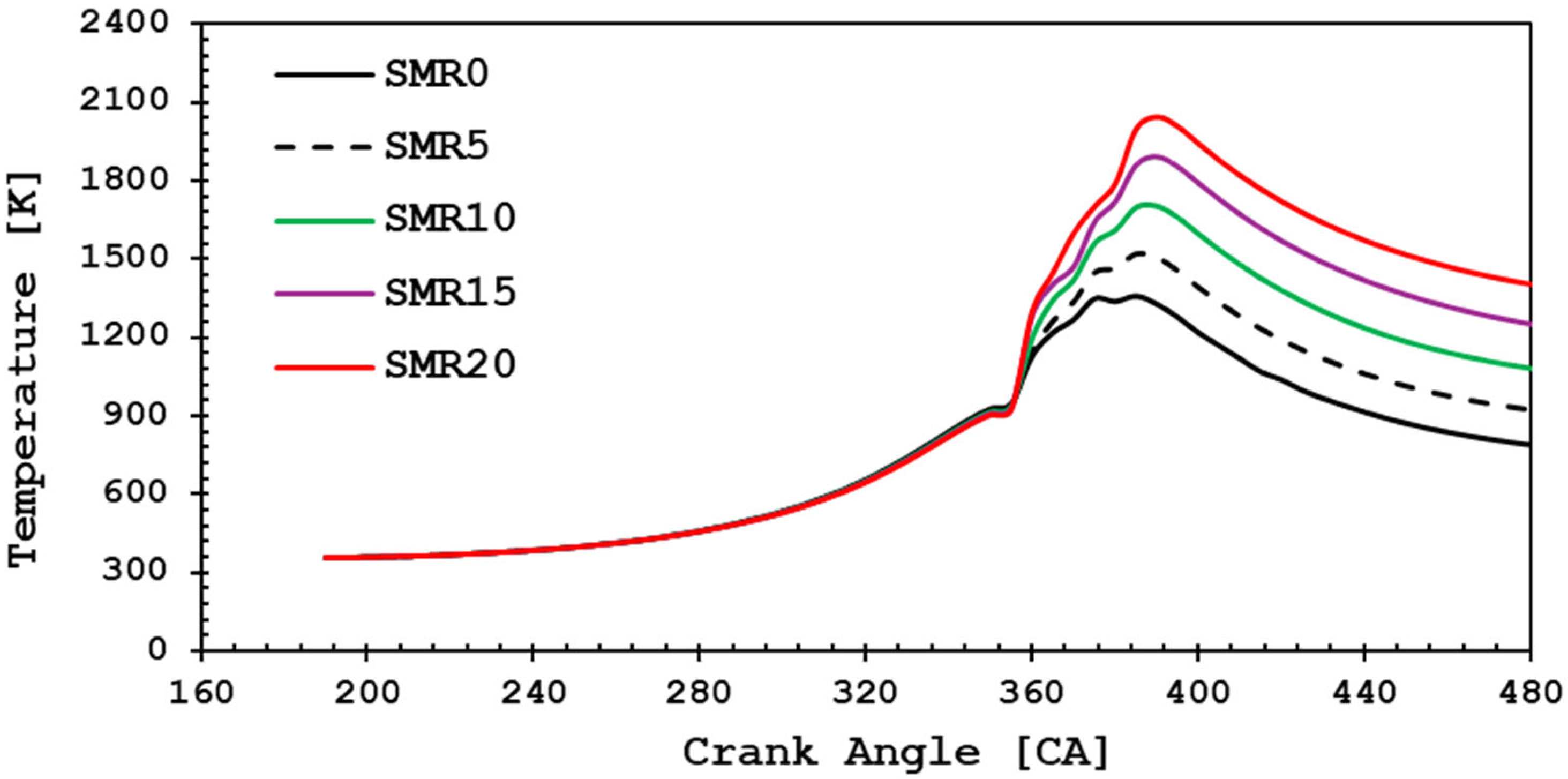
In internal combustion engines, the combustion chamber temperature is one of the primary parameters that contribute to emissions. The optimum adiabatic combustion temperature is maintained at ideal levels to regulate these emissions [46]. However, radiation heat loss results in combustion temperatures being slightly lower than adiabatic flame temperatures. The actual combustion temperature depends mainly on the fuel heating value, the excess air ratio, the combustion air temperature and the combustion zone heat loss by radiation. Figure 7 shows the temperature distribution in the combustion chamber with various SMR gas mixture additive rates. It was determined that the maximum combustion chamber temperatures were approximately 1360 K, 1520 K, 1700 K, 1890 K, and 2040 K for SMR0, SMR5, SMR10, SMR15, and SMR20, respectively. Maximum combustion chamber temperatures occurred at 370 CA. The primary reason for the temperature increase is that the thermal specification and combustion properties of hydrogen produced by the SMR reactor are significantly higher compared to those of diesel fuel. In addition, the combustion chamber temperatures at the exhaust valve opening (EVO) were obtained as approximately 762 K, 893 K, 1050 K, 1210 K, and 1360 K for SMR0, SMR5, SMR10, SMR15, and SMR20, respectively. It was determined that the maximum combustion temperature increase was approximately 11% for SMR5 hydrogen addition and approximately 50% for SMR20 hydrogen addition compared to SMR0. The increase in combustion temperature with hydrogen addition is directly related to the high combustion properties of hydrogen.
Figure 7.
Maximum combustion temperature under various SMR gas addition levels.
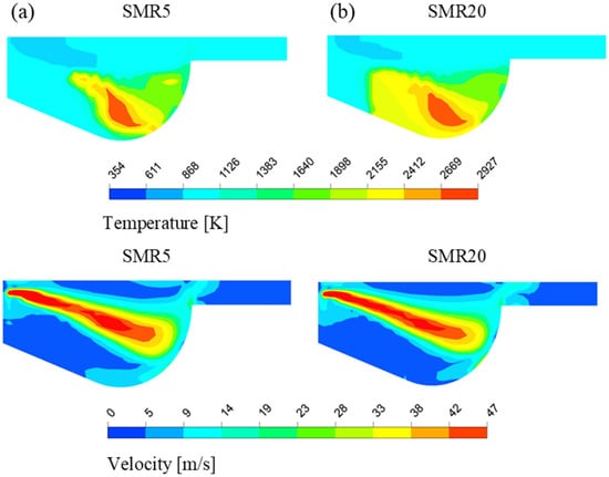
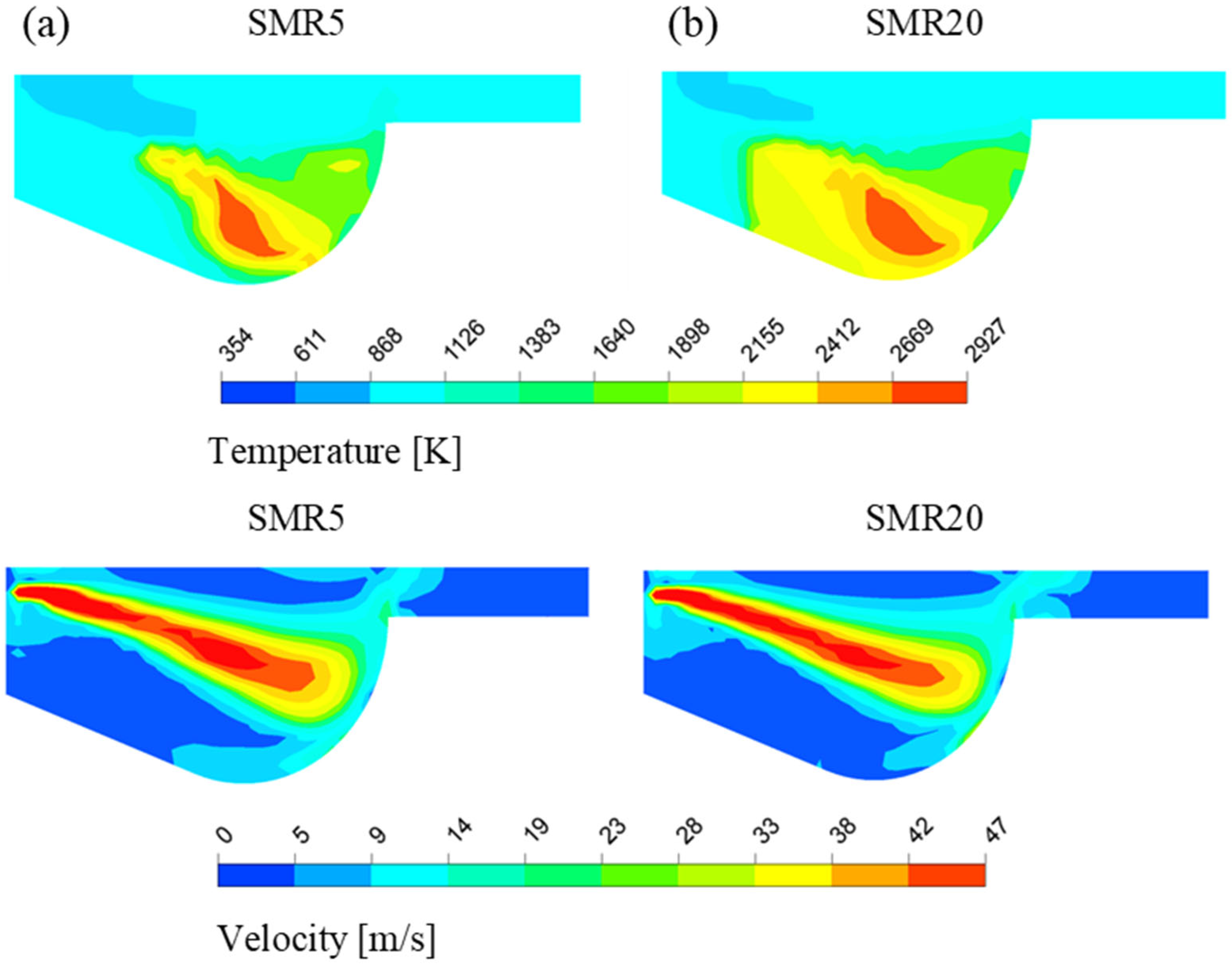
Figure 8 shows the temperature and velocity distributions in the combustion chamber at 360 CA. Heat is generated in the combustion lobe. The temperature distribution for the SMR20 combustion condition covers a wider area than that for SMR0. One of the most important factors here is that hydrogen increases the temperature through promoting pre-combustion reactions. The combustion chamber temperatures reach approximately 2700 K locally. The maximum combustion chamber velocity is 47 m/s at the location of diesel injection. One of the primary parameters that affects the combustion chamber temperature distribution is turbulence, which significantly impacts the air-fuel mixture. One of the most fundamental parameters influencing the combustion chamber temperature distribution is turbulence, which has a significant impact on the air-fuel mixture within the combustion chamber. Turbulence develops in the combustion lobe depending on the chamber geometry, thereby increasing the temperature through its effect on the mixture.
Figure 8.
Temperature and velocity distribution at 360 CA for (a) SMR5 and (b) SMR20 conditions.
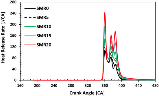
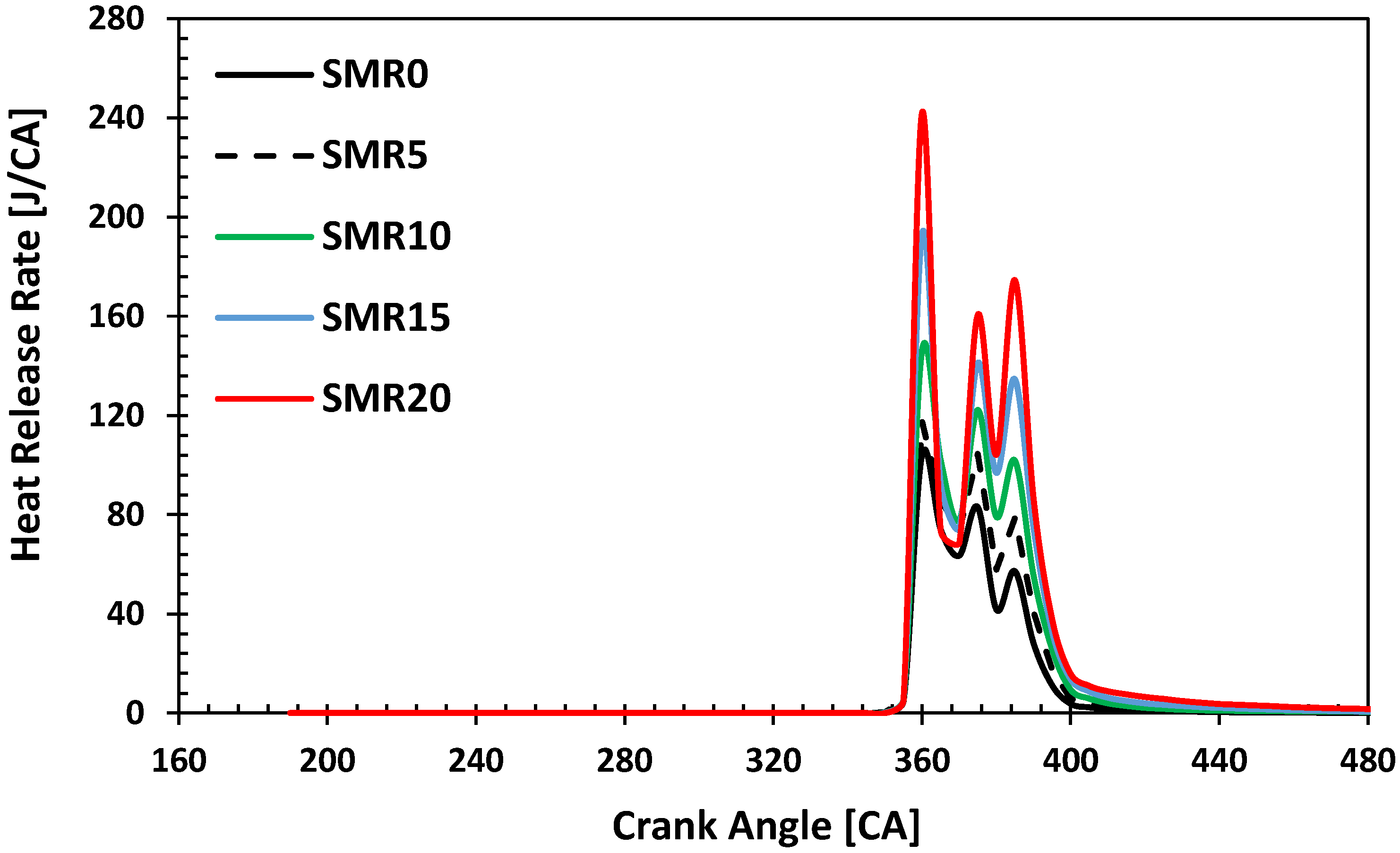
The heat release rate is characterized as the rate at which the chemical energy of the fuel is released during the combustion period [47,48]. The combustion process progresses through four distinct phases. These phases include ignition delay, sudden combustion, controlled combustion, and post-combustion phases [49]. Figure 9 illustrates the effect of adding SMR products to the intake air on the heat release rate. The results show that local maxima in the heat release rate occur during all three combustion phases for all parametric studies. The highest heat release rate occurs at 340 CA. Moreover, increasing the volumetric fraction of the Steam Methane Reforming SMR gas mixture in the intake air increases the heat release rate. Heat release rates peak at approximately 340 CA, 355 CA, and 365 CA. Moreover, the volumetric increase of the Steam methane reformer gas mixture in the air increases the heat release rate. The combustion phases also exhibit similar characteristics, with the second peak occurring during the controlled combustion phase and the final peak during the post-combustion phase. In the case of IC engines, these timings are defined in CA grades, allowing for a comparison of results across various engines. Both physical and chemical principles govern the ignition delay time. The first process depends on the quality of fuel atomization, the technique of distribution into the combustion chamber, and the gas dynamics processes within the engine cylinder. These factors contribute to the phenomenon known as physical ignition delay. The second processes are determined by the chemical properties of the fuel, such as the C/H ratio or oxygen content in the molecular structure, the heat of vaporization value, the ignition temperature, the laminar flame speed (LFS), or the lower heating value (LHV) [50]. When the heat release rates were compared, SMR5, SMR10, SMR15, and SMR20 showed increases of approximately 25%, 56%, 87%, and 116%, respectively, compared to the H0 case due to the addition of hydrogen from SMR. The heat release rate expresses the conversion rate of fuel chemical energy into heat energy. This heat energy is transformed into exhaust energy, mechanical power and heat transfer in the engine.
Figure 9.
Heat release rate (HRR) profiles at different SMR gas ratios.
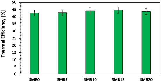
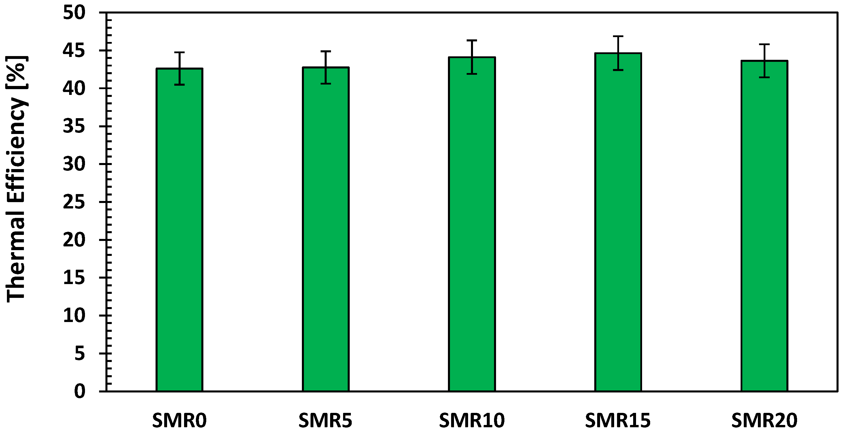
Figure 10 illustrates the impact of SMR outlet gas addition at varying ratios on thermal efficiency. For all analyzed SMR exhaust gas ratios, the engine demonstrated higher thermal efficiency compared to the case where only 15% SMR outlet gas was added to the intake air. Furthermore, the SMR15 condition yielded the highest thermal efficiency, indicating the existence of an optimal syngas blending ratio. This is attributed to reduced combustion efficiency and a lower air–fuel ratio at higher SMR ratios. The thermal efficiencies for SMR0, SMR5, SMR10, SMR15 and SMR20 were found to be approximately 42.6%, 42.7%, 44.1%, 44.6% and 43.6%, respectively. Therefore, the optimal thermal performance increases with the SMR enrichment rate but declines after a certain threshold. Determination of the optimal value is essential for the performance of combined SMR-combustion systems. The thermal efficiency does not increase in correlation with pressure, temperature, and heat release rate because the amount of hydrogen fuel increases with increasing SMR ratios, and accordingly, the performance parameters also increase. However, since thermal efficiency represents the power obtained per unit of fuel energy, it decreases beyond a certain level of SMR gas addition. There was no significant change in engine efficiency when using hydrogen. One of the main reasons is that total exhaust temperatures and heat losses through the engine walls are higher when the SMR-produced gas is added. The engine heat loss varies from 460 J to 757 J between SMR0 and SMR20. The rise in exhaust temperature also leads to increased exhaust energy.
Figure 10.
Thermal efficiency trends with increasing SMR fractions.
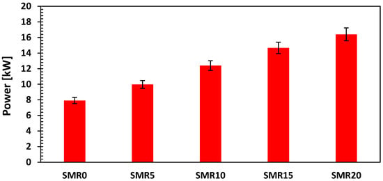
The most important parameters determining power and performance in internal combustion engines are combustion chamber pressure and indicated mean effective pressure (IMEP). Figure 11 shows the variation in engine power with different hydrogen additions to the intake air. Similar to the combustion chamber pressure, engine power increases with the addition of SMR outlet gas. The engine powers for the SMR0, SMR5, SMR10, SMR15, and SMR20 cases are approximately 7.9 kW, 9.9 kW, 12.39 kW, 14.66 kW, and 16.41 kW, respectively. Compared to SMR0, the engine power increases by approximately 15.8% for SMR5 and by approximately 107% for SMR20. However, although the engine power increases due to increased losses, there is no significant increase in thermal energy.
Figure 11.
Variation of engine power output with SMR syngas addition.
3.2. Emission Parameters
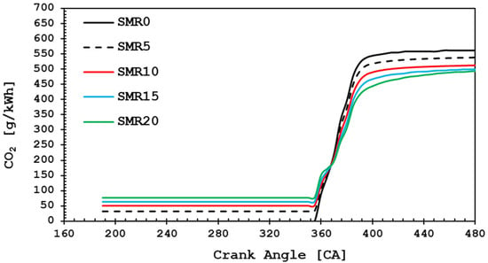
Carbon atoms in the fuel are the primary source of CO2 emissions in combustion processes. Figure 12 shows the effect of SMR outlet gas addition to the intake air at different ratios on CO2 emissions. The increase in SMR outlet gas addition to the combustion air reduces carbon emissions. Approximately 46% of the steam methane reformer reactor outlet gas, by volume, consists of H2. Hydrogen significantly influences CO2 emissions due to its carbon-free nature and high thermal efficiency. Initially, as a result of the SMR reactions, the presence of CO2 increases the CO2 concentration in the combustion chamber. However, when the amount of reformer gases in the combustion chamber increases, the amount of CO2 per unit of energy output (kWh) decreases due to the rising engine power. Compared to SMR0, CO2 emissions are reduced by approximately 12% under SMR20 conditions. This rate of increase is proportional to the increase in engine power, rather than the amount of CO2. The hydrogen formed here is derived from diesel fuel combustion and includes hydrogen generated through SMR reactions. Therefore, the total carbon footprint associated with both the reformer and diesel combustion processes used for hydrogen production is taken into consideration. Figure 12 shows the initial CO2 content, approximately 75.9 g/kWh, 63.7 g/kWh, 50.3 g/kWh and 31.2 g/kWh for SMR20, SMR15, SMR10 and SMR5, respectively. The carbon emission factor in combustion processes is approximately 3.2, which is consistent with values reported in the literature [51]. In other words, for diesel fuel, the carbon emission factor corresponds to 3.2 units of CO2 per unit of fuel. Under the diesel combustion conditions (SMR0) considered in this study, the fuel consumption is approximately 190 g/kWh, while CO2 emissions are about 562 g/kWh. The remaining carbon is emitted in the form of CO.
Figure 12.
CO2 emission variation across different SMR ratios.
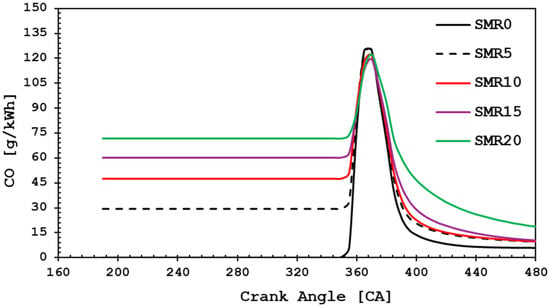
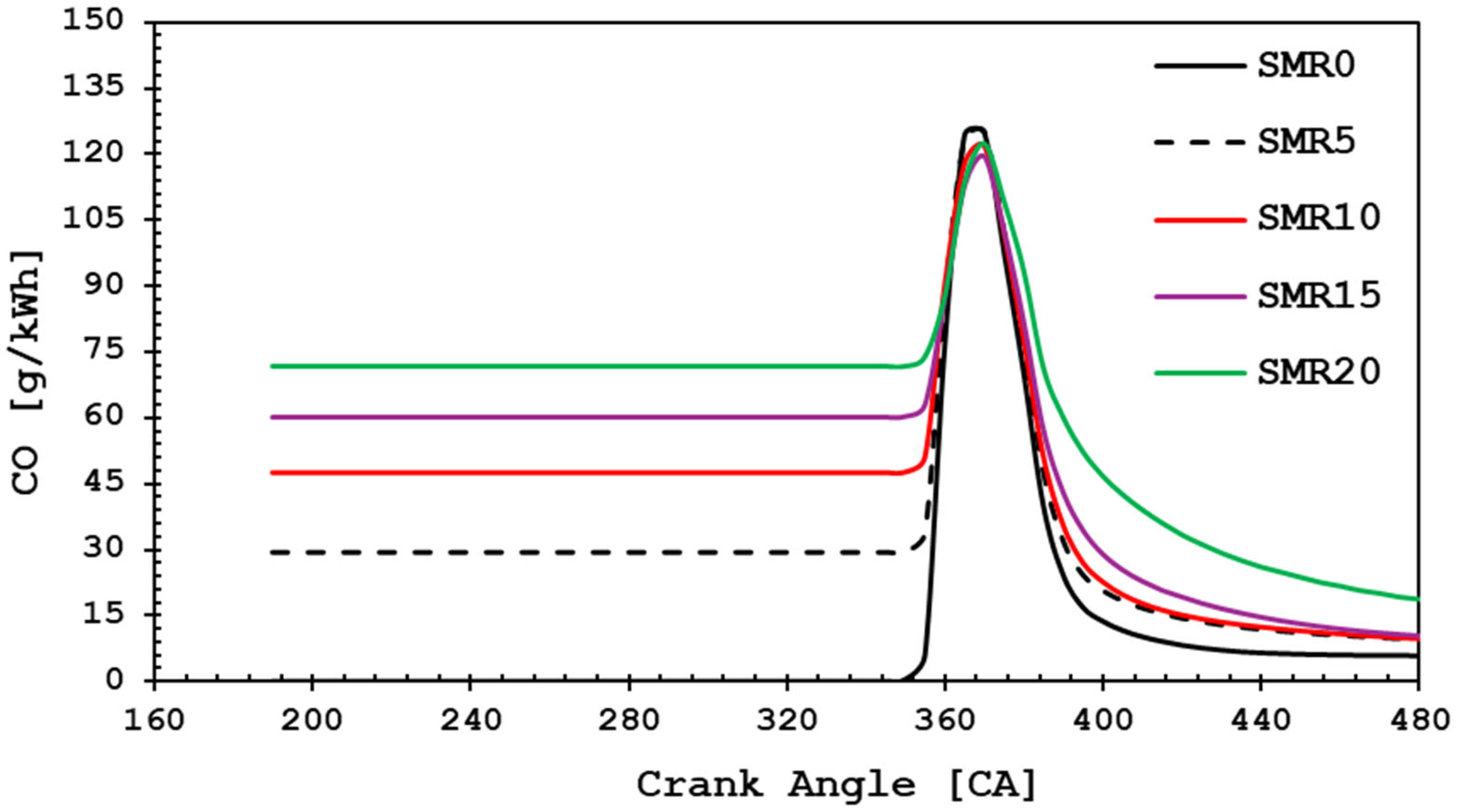
Carbon monoxide emissions and significant residual quantities of unburned solid char particles are often indicators of incomplete combustion and potential operational problems. CO emissions are determined by the combustion of the fuel/air mixture and the amount of carbon in the fuel source. During combustion, the carbon in the fuel oxidizes with the oxygen in the air, producing CO and CO2, depending on the conditions. The carbon in the fuel is not converted into CO2, but rather into CO in the exhaust [52]. Figure 13 shows the change in CO concentration in the combustion chamber according to different Steam methane reformer outlet gas rates. The highest CO concentration was observed at the exhaust valve opening (EVO) for the case with 20% SMR outlet gas addition. This is because the CO produced in the SMR reactor is directly supplied to the combustion chamber with the intake air without undergoing separation. This is because the amount of CO produced in SMR reactors is fed straight to the combustion chamber with the intake air without separation. At high SMR outlet gas ratios in the intake air, the CO concentration in the combustion chamber decreases toward the end of combustion. Depending on the combustion parameters, the decreasing CO is converted to CO2. As a result, the CO level for SMR20, which was initially 71.7 g/kWh, decreased to 18.8 g/kWh after combustion. For SMR0, the CO level, which was initially zero, reached approximately 5.187 g/kWh at the end of combustion. Increasing the SMR ratios reduces CO emissions.
Figure 13.
Variation of CO with different SMR ratios.
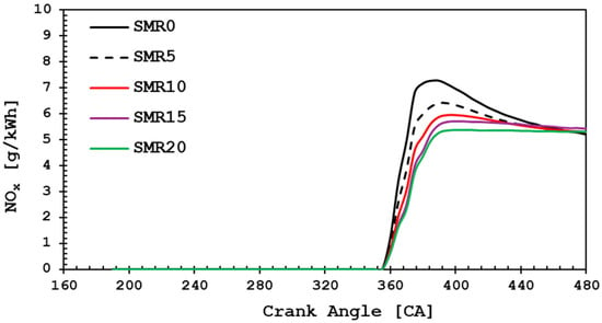
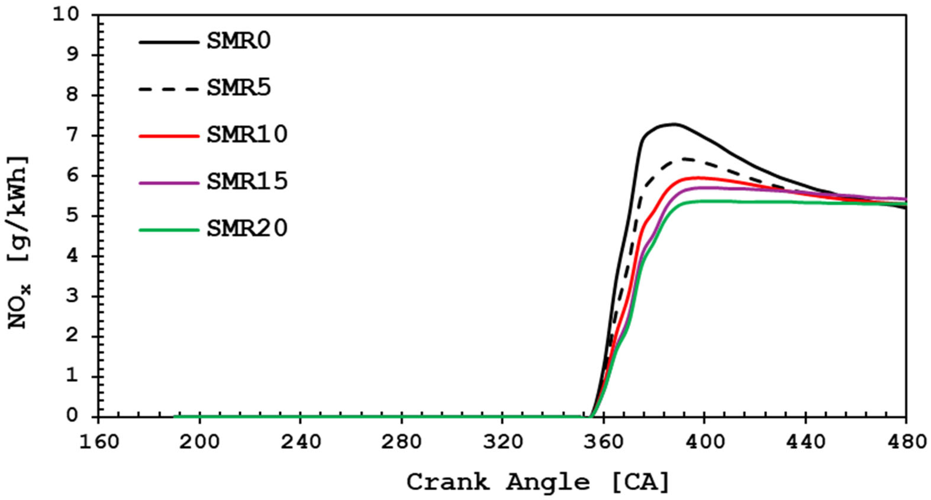
NOx emissions are mainly composed of NO molecules and low levels of NO2. An increase in in-cylinder temperature leads to higher NOx emissions in engines. NO forms as an intermediate product of chemical reactions involving nitrogen and oxygen atoms and molecules in the high-temperature gases behind the flame during the combustion process. Figure 14 shows the variation in NOx emissions in the combustion chamber with different SMR gas blend additions. As the SMR outlet gas addition to the intake air increases, NOx emissions also increase. These increasing values follow a trend similar to that of the combustion chamber temperatures. One of the primary parameters influencing NOx emissions in internal combustion engines is thermal NO, as described in the Zeldovich mechanism [53]. When 20% SMR outlet gas is added to the combustion chamber, the temperature rises significantly due to the higher hydrogen content, which enhances combustion but also leads to increased NOx emissions. NOx emissions show characteristics similar to those in the literature [54]. However, it is essential to note that all emissions in the combustion chamber are directly proportional to engine speed and ignition delay.
Figure 14.
NOx emission characteristics with increasing SMR syngas content.
The NOx emissions predicted in this study rely on the extended Zeldovich mechanism, which captures high-temperature thermal NO formation. However, this approach does not explicitly account for prompt (Fenimore) NOx originating from CH radicals or fuel-bound NOx associated with CO/CH4 components of the SMR-derived syngas. As a result, the absolute NOx values may be underestimated by approximately 10–15%, consistent with prior literature. Nevertheless, because all fuel cases were simulated within the same chemical and numerical framework, the comparative NOx trends between diesel-only and syngas-blended operation remain valid. Future work will incorporate detailed chemistry models, such as GRI-Mech or USC-Mech, to resolve CH–N interaction pathways and provide more comprehensive NOx predictions.
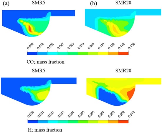
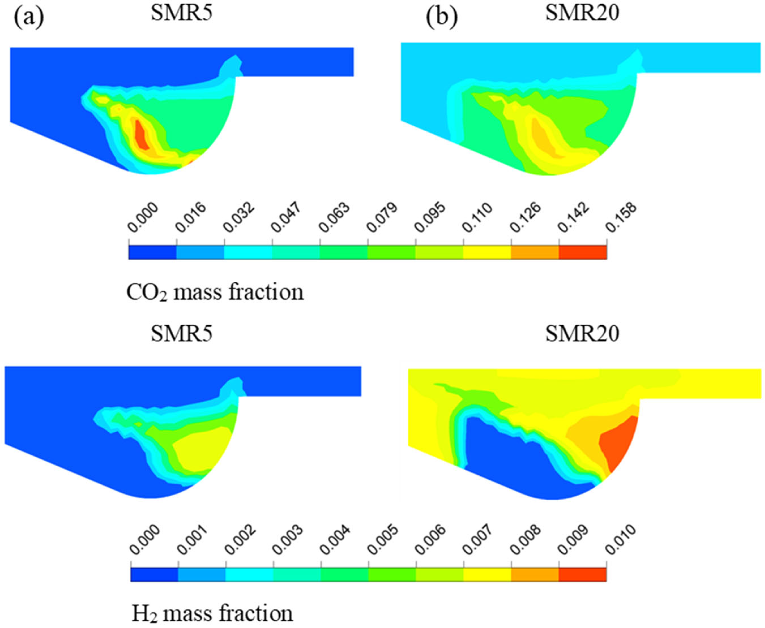
Figure 15 shows the CO2 and H2 distribution for combustion chamber 720 CA. It is seen that CO2 emissions are more intense in the combustion chamber for SMR5 than for SMR20. The increased regional intensity of CO2 emissions is due to the enhanced combustion performance provided by the hydrogen additive. Additionally, the carbon-free nature of H2 is a primary reason for the reduction in CO2 emissions. The minimum formation of CO2 in the injection zone is attributed to the production of combustion gases in the combustion lobe, resulting from the fuel injection velocity. The H2 content is higher in the Steam Methane Reforming (SMR) integrated system because it is supplied from the intake manifold along with SMR gas. The distribution of hydrogen in the combustion chamber enhances the combustion performance of the system, depending on the combustion pressure and temperature. It was determined that the maximum mass fraction of CO2 in the combustion chamber was approximately 15%, while that of H2 was approximately 10%. As a result, the distribution of gases generated by the steam methane reformer plays a crucial role in reducing CO2 emissions and enhancing system performance.
Figure 15.
Mass fraction distribution of CO2 and H2 in the combustion chamber for (a) SMR5 and (b) SMR20 conditions.
Although the current CFD framework focuses on steady-state partial-load operation, the model can be readily extended to full-load and transient engine conditions. Such an extension would enable the evaluation of fuel–air mixing dynamics, peak temperature evolution, and syngas–diesel combustion stability under rapidly changing load and speed conditions. More importantly, transient-cycle simulations would provide the necessary input for system-level well-to-wheel (WTW) assessments, enabling the quantification of total CO2 savings when unseparated SMR syngas is integrated into dual-fuel diesel engines. Future work will therefore incorporate load-sweep simulations and representative driving cycles to capture time-resolved NOx formation, exergy losses, and WTW greenhouse-gas reductions.
Compared to on-board methanol reforming, the direct integration of unseparated SMR-derived syngas differs fundamentally in terms of mixture formation, thermal management and combustion chemistry. While SMR syngas is externally produced with a relatively stable H2–CO–CO2 composition, on-board reforming yields a highly hydrogen-rich but thermally sensitive gas whose composition varies with the availability of exhaust heat. Furthermore, LCA-based sustainability metrics indicate that SMR integration provides advantages by shifting process complexity to plant-level reformers, reducing on-engine hardware requirements, and enabling more predictable carbon-displacement performance depending on the upstream energy source. From a life-cycle perspective, the use of unseparated SMR syngas also offers an additional advantage by eliminating the energy-intensive steps required for hydrogen storage and distribution. Conventional hydrogen pathways require compression up to 350–700 bar, liquefaction at −253 °C, or transportation in specialized tanks, all of which significantly increase well-to-tank CO2 emissions. In contrast, syngas can be delivered through existing industrial pipelines or produced on-site without high-pressure storage. Therefore, the syngas-based dual-fuel strategy reduces both upstream energy demand and associated greenhouse gas emissions, thereby strengthening its sustainability performance compared to hydrogen-only or methanol-reforming alternatives.
4. Conclusions
Transport and storage remain the two main barriers to the widespread adoption of hydrogen as a fuel. This study addressed the critical barriers to hydrogen adoption—transport and storage—by proposing and evaluating an integrated system where hydrogen-rich syngas from a steam methane reformer (SMR) is used directly in a diesel engine. The numerical analysis shows that this method effectively eliminates the requirement for independent infrastructure for hydrogen separation, storage, and transportation. The main findings can be summarized as follows:
- Increasing the SMR outlet gas ratio in the intake air significantly enhanced in-cylinder combustion, leading to higher pressure and temperature levels. Under SMR20 conditions, pressure and temperature increased by approximately 16% and 50%, respectively, compared to baseline diesel operation.
- Engine performance improved with increasing SMR fractions. Power output increased by more than 16%, while thermal efficiency showed a moderate rise, indicating the potential of SMR syngas to enhance engine performance.
- CO2 emissions were reduced by nearly 12% under SMR20 conditions, confirming the effectiveness of hydrogen-rich syngas in lowering carbon footprints.
- A trade-off was observed in the form of higher NOx formation, which increased slightly with greater hydrogen content due to elevated combustion temperatures.
- The integrated SMR–diesel system provides a novel pathway to overcome hydrogen storage and transport challenges, offering a practical contribution to global net-zero strategies.
This study was limited to numerical modeling; therefore, future research should focus on experimental validation, the use of different reformer types, and the application of emission control strategies (e.g., EGR, SCR, injection optimization) to minimize NOx while preserving efficiency. By coupling hydrogen production and utilization in a single system, the proposed approach highlights a feasible transition strategy toward cleaner and more sustainable energy systems.
Author Contributions
Conceptualization, K.B. and T.B.; methodology, K.B. and T.B.; software, K.B.; validation, K.B.; formal analysis, K.B.; investigation, S.Y.; resources, K.D.K.; data curation, T.B.; writing—original draft preparation, K.B. and S.Y.; writing—review and editing, T.B. and K.D.K.; visualization, K.B.; supervision, K.B.; project administration, T.B.; funding acquisition, T.B. All authors have read and agreed to the published version of the manuscript.
Funding
This research received no external funding.
Institutional Review Board Statement
Not applicable.
Informed Consent Statement
Not applicable.
Data Availability Statement
The original contributions presented in this study are included in the article. Further inquiries can be directed to the corresponding author.
Conflicts of Interest
The authors declare no conflict of interest.
References
- Zhu, X.M.; Sun, Z.Y.; Liu, X.Y. Impacts of Hydrogen Fraction and Equivalence Ratio on the Explosion Characteristics of Ethanol/Hydrogen Mixtures. Fuel 2024, 375, 132620. [Google Scholar] [CrossRef] [Scilit]
- Yin, C.; Wang, C.; Shen, X.; Zhang, Z. Experimental and Simulation Study of Diesel/Methane/Hydrogen Triple-Fuel Combustion Progression in a Heavy-Duty Optical Engine. Int. J. Hydrogen Energy 2024, 62, 562–578. [Google Scholar] [CrossRef] [Scilit]
- European Commission. The European Green Deal; European Commission: Brussels, Belgium, 2019. [Google Scholar]
- United Nations. Net Zero Coalition; United Nations (UN): New York, NY, USA, 2023. [Google Scholar]
- Gonzalez-Arceo, A.; Blanco-Aguilera, R.; Berasategi, J.; Martinez-Agirre, M.; Martinez, A.; Iglesias, G.; Penalba, M. Techno-Economic Assessment of Far-Offshore Hydrogen-Carrying Energy Vectors off the Iberian Peninsula. Energy Convers. Manag. 2024, 300, 117915. [Google Scholar] [CrossRef] [Scilit]
- Habib, M.A.; Abdulrahman, G.A.Q.; Alquaity, A.B.S.; Qasem, N.A.A. Hydrogen Combustion, Production, and Applications: A Review. Alex. Eng. J. 2024, 100, 182–207. [Google Scholar] [CrossRef] [Scilit]
- Yan, Y.; Thanganadar, D.; Clough, P.T.; Mukherjee, S.; Patchigolla, K.; Manovic, V.; Anthony, E.J. Process Simulations of Blue Hydrogen Production by Upgraded Sorption Enhanced Steam Methane Reforming (SE-SMR) Processes. Energy Convers. Manag. 2020, 222, 113144. [Google Scholar] [CrossRef] [Scilit]
- Ağbulut, Ü.; Vozka, P.; Bakır, H.; Brieu, N.A.; Polat, F.; Sarıdemir, S. On-Board Hydrogen-Rich Syngas Production via Waste Heat Recovery from Compression-Ignition Engines: Maximizing Hydrogen Content with Novel Multi-Objective Algorithms. Int. J. Hydrogen Energy 2025, 130, 411–422. [Google Scholar] [CrossRef] [Scilit]
- Afanasev, P.; Askarova, A.; Alekhina, T.; Popov, E.; Markovic, S.; Mukhametdinova, A.; Cheremisin, A.; Mukhina, E. An Overview of Hydrogen Production Methods: Focus on Hydrocarbon Feedstock. Int. J. Hydrogen Energy 2024, 78, 805–828. [Google Scholar] [CrossRef] [Scilit]
- Barokh, H.; Siavashi, M. Pore-Scale Direct Numerical Simulation of Steam Methane Reforming (SMR) for Hydrogen Production in Open-Cell Porous Catalytic Foam. Int. J. Hydrogen Energy 2024, 83, 1294–1308. [Google Scholar] [CrossRef] [Scilit]
- Bayramoğlu, K.; Yılmaz, S.; Çoban, M.T. Numerical Analysis of Hydrogen Production by Methanol and Methane Steam Reforming Using Compact Reactors. Therm. Sci. Eng. Prog. 2025, 58, 103238. [Google Scholar] [CrossRef] [Scilit]
- Guo, S.; Lou, Z.; Huang, F.; Wang, L.; Liu, H.; Hou, Z.; Yang, Z.; Zhang, X. Effect of Hydrogen/Ammonia Mixing Ratio on Combustion and Emission Performance of Hydrogen Engine with Different Injection Timing. Int. J. Hydrogen Energy 2024, 78, 157–168. [Google Scholar] [CrossRef] [Scilit]
- Nakkeeran, K.; Victor, K. Grey and Blue Hydrogen: Insights into Production Technologies and Outlook on CO2-Free Alternatives. Sustain. Energy Technol. Assess. 2025, 75, 104222. [Google Scholar] [CrossRef] [Scilit]
- Chang, K.P.; Law, Z.X.; Du, C.B.; Pao, C.W.; Chen, T.Y.; Tsai, D.H. Methane-Steam Reforming for Low-Carbon Hydrogen Production Using Ni-Pd Bimetallic Nanoparticle Cluster. Fuel 2025, 399, 135683. [Google Scholar] [CrossRef] [Scilit]
- Szablowski, L.; Wojcik, M.; Dybinski, O. Review of Steam Methane Reforming as a Method of Hydrogen Production. Energy 2025, 316, 134540. [Google Scholar] [CrossRef] [Scilit]
- Masoudi Soltani, S.; Lahiri, A.; Bahzad, H.; Clough, P.; Gorbounov, M.; Yan, Y. Sorption-Enhanced Steam Methane Reforming for Combined CO2 Capture and Hydrogen Production: A State-of-the-Art Review. Carbon Capture Sci. Technol. 2021, 1, 100003. [Google Scholar] [CrossRef] [Scilit]
- Bayramoğlu, K.; Bayramoğlu, T. Integrated Modeling of Steam Methane Reforming and Carbon Capture for Blue Hydrogen Production. Hydrogen 2025, 6, 94. [Google Scholar] [CrossRef] [Scilit]
- Ma, J.; Jiang, B.; Li, L.; Yu, K.; Zhang, Q.; Lv, Z.; Tang, D. A High Temperature Tubular Reactor with Hybrid Concentrated Solar and Electric Heat Supply for Steam Methane Reforming. Chem. Eng. J. 2022, 428, 132073. [Google Scholar] [CrossRef] [Scilit]
- Rong, Y.; Chen, S.; Li, C.; Chen, X.; Xie, L.; Chen, J.; Long, R. Techno-Economic Analysis of Hydrogen Storage and Transportation from Hydrogen Plant to Terminal Refueling Station. Int. J. Hydrogen Energy 2024, 52, 547–558. [Google Scholar] [CrossRef] [Scilit]
- Barokh, H.; Siavashi, M.; Tousi, R. The Role of Voronoi Catalytic Porous Foam in Reactive Flow for Hydrogen Production through Steam Methane Reforming (SMR): A Pore-Scale Investigation. Int. J. Hydrogen Energy 2024, 141, 369–383. [Google Scholar] [CrossRef] [Scilit]
- Kumar, R.; Kumar, A.; Pal, A. Simulation Modelling of Hydrogen Production from Steam Reforming of Methane and Biogas. Fuel 2024, 362, 130742. [Google Scholar] [CrossRef] [Scilit]
- Devasahayam, S.; Thella, J.S.; Mohanty, M.K. Sustainability Assessment of Dry Reforming of Methane via Carbon Intensity and Syngas Energy Recovery Analysis. Energies 2025, 18, 6307. [Google Scholar] [CrossRef] [Scilit]
- Amini, A.; Anaraki Haji Bagheri, A.; Sedaghat, M.H.; Rahimpour, M.R. CFD Simulation of an Industrial Steam Methane Reformer: Effect of Burner Fuel Distribution on Hydrogen Production. Fuel 2023, 352, 129008. [Google Scholar] [CrossRef] [Scilit]
- Mehanovic, D.; Al-Haiek, A.; Leclerc, P.; Rancourt, D.; Fréchette, L.; Picard, M. Energetic, GHG, and Economic Analyses of Electrified Steam Methane Reforming Using Conventional Reformer Tubes. Energy Convers. Manag. 2023, 276, 116549. [Google Scholar] [CrossRef] [Scilit]
- Sayer, M.; Ajanovic, A.; Haas, R. Economic and Environmental Assessment of Different Hydrogen Production and Transportation Modes. Int. J. Hydrogen Energy 2024, 65, 626–638. [Google Scholar] [CrossRef] [Scilit]
- Qiao, Y.; Jiang, W.; Li, Y.; Dong, X.; Yang, F. Developed a New Steam Methane Reforming, Hydrogen Liquefaction, and Waste Heat Recovery System Based on LNG Cold Energy. Energy 2024, 302, 131792. [Google Scholar] [CrossRef] [Scilit]
- Sekar, M.; Alahmadi, T.A.; Nithya, S. Numerical Simulation of Industrial Gas Burners Fueled with Hydrogen-Methane Mixtures for Enhanced Combustion Efficiency and Reduced Greenhouse Gas Emissions. Fuel 2024, 370, 131807. [Google Scholar] [CrossRef] [Scilit]
- Qiang, Y.; Cai, X.; Xu, S.; Wang, F.; Zhang, L.; Wang, S.; Ji, C. Effect of Injection Strategy on the Hydrogen Mixture Distribution and Combustion of the Hydrogen-Fueled Engine with Passive Pre-Chamber Ignition under Lean Burn Condition. Fuel 2024, 375, 132610. [Google Scholar] [CrossRef] [Scilit]
- Bayramoğlu, K.; Yılmaz, S. Emission and Performance Estimation in Hydrogen Injection Strategies on Diesel Engines. Int. J. Hydrogen Energy 2021, 46, 29732–29744. [Google Scholar] [CrossRef] [Scilit]
- Sattarzadeh, M.; Ebrahimi, M.; Jazayeri, S.A. A Detail Study of a RCCI Engine Performance Fueled with Diesel Fuel and Natural Gas Blended with Syngas with Different Compositions. Int. J. Hydrogen Energy 2022, 47, 16283–16296. [Google Scholar] [CrossRef] [Scilit]
- Piano, A.; Pucillo, F.; Millo, F.; Giordana, S.; Rapetto, N.; Schuette, C. Experimental Investigation on the Optimal Injection and Combustion Phasing for a Direct Injection Hydrogen-Fuelled Internal Combustion Engine for Heavy-Duty Applications. Int. J. Hydrogen Energy 2025, 100, 398–406. [Google Scholar] [CrossRef] [Scilit]
- Kandasamy, K.; Dhairiyasamy, R.; Gabiriel, D. Optimizing Dual Fuel Engine Performance with Hydrogen-Enriched Syngas from Co-Pyrolysis of Biodegradable and Non-Biodegradable Wastes. Int. J. Hydrogen Energy 2025, 149, 150156. [Google Scholar] [CrossRef] [Scilit]
- Lim, T.-W.; Hwang, D.-H.; Choi, Y.-S. Design and Optimization of a Steam Methane Reformer for Ship-Based Hydrogen Production on LNG-Fueled Ship. Appl. Therm. Eng. 2024, 243, 122588. [Google Scholar] [CrossRef] [Scilit]
- Tran, A.; Aguirre, A.; Durand, H.; Crose, M.; Christofides, P.D. CFD Modeling of an Industrial-Scale Steam Methane Reforming Furnace. Chem. Eng. Sci. 2017, 171, 576–598. [Google Scholar] [CrossRef] [Scilit]
- Lao, L.; Aguirre, A.; Tran, A.; Wu, Z.; Durand, H.; Christofides, P.D. CFD Modeling and Control of a Steam Methane Reforming Reactor. Chem. Eng. Sci. 2016, 148, 78–92. [Google Scholar] [CrossRef] [Scilit]
- Bayramoğlu, K. Determination of Hydrogen Production Performance with Waste Exhaust Gas in Marine Diesel Engines. Int. J. Hydrogen Energy 2024, 52, 1319–1333. [Google Scholar] [CrossRef] [Scilit]
- Zhang, Z.; Hu, J.; Yang, D.; Yin, Z.; Lu, K.; Tan, D. A Comprehensive Assessment over the Environmental Impact and Combustion Efficiency of Using Ammonia/ Hydrogen/Diesel Blends in a Diesel Engine. Energy 2024, 303, 131955. [Google Scholar] [CrossRef] [Scilit]
- Amiri, T.Y.; Ghasemzageh, K.; Iulianelli, A. Membrane Reactors for Sustainable Hydrogen Production through Steam Reforming of Hydrocarbons: A Review. Chem. Eng. Process. Process Intensif. 2020, 157, 108148. [Google Scholar] [CrossRef] [Scilit]
- Bayramoğlu, K.; Yilmaz, S.; Nuran, M. Energy and Exergy Analyses of Hydrogen Addition in a Diesel Engine. Int. J. Exergy 2022, 37, 377–392. [Google Scholar] [CrossRef] [Scilit]
- Patel, A.; Kong, S.-C.; Reitz, R.D. Development and Validation of a Reduced Reaction Mechanism for HCCI Engine Simulations. SAE Tech. Pap. Ser. 2004, 149, 748–759. [Google Scholar] [CrossRef] [Scilit]
- ANSYS, Inc. ANSYS Forte 17.2 Theory Guide; ANSYS, Inc.: Canonsburg, PA, USA, 2015; pp. 1–110. [Google Scholar]
- Bayramoğlu, K.; Nuran, M. Analyzing the Effect of Fuel Injection Timing and Injection Duration on Performance and Emissions in Diesel Engines. J. ETA Marit. Sci. 2020, 8, 38–52. [Google Scholar] [CrossRef] [Scilit]
- ANSYS, Inc. ANSYS Forte 17.2 Users Guide; ANSYS, Inc.: Canonsburg, PA, USA, 2016; pp. 1–292. [Google Scholar]
- Lakshmikanth, G.; Sudarsanam, M.; Balaji, N.; Subbiah, G.; Sakthimurugan, V.; Madhu, S.; Ahmad, M. International Journal of Hydrogen Energy Performance, Combustion, and Emission Evaluation of Cassia Fistula Biodiesel Blends with Hydrogen Induction in a Low Heat Rejection Diesel Engine. Int. J. Hydrogen Energy 2025, 143, 468–478. [Google Scholar] [CrossRef] [Scilit]
- Rosen, M.A.; Koohi-Fayegh, S. The Prospects for Hydrogen as an Energy Carrier: An Overview of Hydrogen Energy and Hydrogen Energy Systems. Energy Ecol. Environ. 2016, 1, 10–29. [Google Scholar] [CrossRef] [Scilit]
- McAllister, S.; Chen, J.-Y.; Fernandez-Pello, A.C. Fundamentals of Combustion Processes; Springer: New York, NY, USA, 2011; ISBN 978-1-4419-7942-1. [Google Scholar]
- Alvarez, C.E.C.; Couto, G.E.; Roso, V.R.; Thiriet, A.B.; Valle, R.M. A Review of Prechamber Ignition Systems as Lean Combustion Technology for SI Engines. Appl. Therm. Eng. 2018, 128, 107–120. [Google Scholar] [CrossRef] [Scilit]
- Chengji, Z.; Zhao, K. A Study on the Combustion System of a Spark Ignition Natural Gas Engine; SAE Technical Paper 981386; SAE International: Warrendale, PA, USA, 1998. [Google Scholar]
- Ricardo, S.H. Combustion in Diesel Engines. Proc. Inst. Mech. Eng. 1950, 162, 145–148. [Google Scholar] [CrossRef] [Scilit]
- Tutak, W.; Rogalinski, K.G.; Jamrozik, A. Combustion and Emission Characteristics of a Biodiesel-Hydrogen Dual-Fuel Engine. Appl. Sci. 2020, 10, 1082. [Google Scholar] [CrossRef] [Scilit]
- Wang, K.; Zhao, B.; Fan, T.; Zhang, J. Economic Growth Targets and Carbon Emissions: Evidence from China. Int. J. Environ. Res. Public Health 2022, 19, 8053. [Google Scholar] [CrossRef] [Scilit]
- Ramalingam, S.; Rajendran, S. Assessment of Performance, Combustion, and Emission Behavior of Novel Annona Biodiesel-Operated Diesel Engine. In Advances in Eco-Fuels for a Sustainable Environment; Azad, K., Ed.; Woodhead Publishing Series in Energy; Woodhead Publishing: Cambridge, UK, 2019; pp. 391–405. ISBN 978-0-08-102728-8. [Google Scholar]
- Zeldovich, Y.B. The Oxidation of Nitrogen in Combustion and Explosions. Acta Physicochim. USSR 1946, 4, 577–628. [Google Scholar] [CrossRef] [Scilit]
- Akhtar, M.U.S.; Asfand, F.; Khan, M.I.; Mishra, R.; Ball, A.D. Performance and Emissions Characteristics of Hydrogen-Diesel Dual-Fuel Combustion for Heavy-Duty Engines. Int. J. Hydrogen Energy 2025, 143, 454–467. [Google Scholar] [CrossRef] [Scilit]

Disclaimer/Publisher’s Note: The statements, opinions and data contained in all publications are solely those of the individual author(s) and contributor(s) and not of MDPI and/or the editor(s). MDPI and/or the editor(s) disclaim responsibility for any injury to people or property resulting from any ideas, methods, instructions or products referred to in the content. |
© 2026 by the authors. Licensee MDPI, Basel, Switzerland. This article is an open access article distributed under the terms and conditions of the Creative Commons Attribution (CC BY) license.