


Abstract
The growing demand for reinforced concrete (RC) structures, driven by population growth, significantly contributes to carbon emissions, particularly during the construction phase. Steel rebar production, a major contributor to these emissions, faces challenges due to high material consumption and waste, often stemming from market-length rebar and conventional lap splices, impeding decarbonization efforts. This study introduces a comprehensive strategy to minimize rebar consumption and waste, advancing decarbonization in the civil and construction industry. The strategy integrates a special-length-priority minimization algorithm with lap splice position adjustments or couplers to reduce rebar consumption, waste, and carbon emissions. A case study evaluates distinct scenarios regarding rebar consumption. The study demonstrates that conventional rebar practices, such as market-length rebar and lap splices, lead to excessive consumption and waste, impeding decarbonization. Couplers significantly reduce rebar requirements, though cutting waste remains when combined with market-length rebar. Special-length-priority optimization with lap splice adjustments demonstrates greater efficiency in reducing consumption while minimizing cutting waste, proving effectiveness. The combination of special-length-priority optimization and couplers achieves the greatest reductions in rebar consumption, waste, and carbon emissions, making it the most efficient strategy for future construction projects. These findings emphasize the importance of optimizing rebar consumption in advancing decarbonization and promoting sustainable practices in the civil and construction industry.
1. Introduction
The construction industry encounters a critical obstacle in decarbonization due to its reliance on carbon-intensive materials, particularly steel rebar, which significantly drives global greenhouse gas emissions. As urban populations are projected to increase by 2.4 billion by 2050 [1], the demand for civil and construction works, particularly those involving reinforced concrete (RC), is expected to surge, exacerbating the current housing shortage and inadequate infrastructure [2]. RC construction is essential for energy, water, wastewater systems, buildings, and transportation networks [2]. With this surge in RC construction comes a corresponding rise in the consumption of concrete and steel rebar. Rebar usage consistently faces challenges from cutting waste, estimated at 3–5% during the design stage and frequently exceeding 5% during construction [3]. Often overlooked in many projects, this issue highlights the need for effective minimization strategies.
Consequently, various methods, including cutting waste optimization and coupler usage, have been introduced to address the persistent challenges of high rebar waste and material consumption. Extensive research on rebar minimization has struggled to achieve significant reductions due to the reliance on market or standard rebar lengths, which perpetuates high cutting waste and rebar consumption [4,5,6], leaving them unresolved. Studies [4,7] demonstrate that integrating lap splice position adjustments or couplers with special-length-priority rebar optimization can substantially decrease both cutting waste and material usage. By eliminating lap splicing, couplers reduce rebar requirements and utilize their mechanical properties to establish robust connections. However, their adoption requires careful planning in procurement, installation, and specialized equipment, leading to hesitancy among engineers. Nevertheless, recent findings [4,8] indicate that the advantages of couplers outweigh these challenges, offering up to a 26% reduction in construction costs and a 95% decrease in environmental impact compared to traditional methods. These insights accentuate the need for further research to refine strategies that mitigate the environmental and construction impacts of rebar usage.
The built environment, encompassing the civil and construction industry, contributes approximately 40% of global carbon emissions and natural resource consumption [9,10]. This significant impact largely arises from the production and consumption of carbon-intensive materials [11], such as concrete and rebar, which together account for 65% of construction-related greenhouse gas emissions, with rebar alone contributing 60% of this total [12]. Emissions throughout the product lifecycle, from raw material extraction to disposal, emphasize the indispensable need to minimize rebar emissions, as the construction phase significantly drives the industry’s carbon intensity. Lifecycle assessments reveal that rebar’s carbon footprint ranges from 1.03 to 3.5 tons of CO2-e per ton [11,13,14,15,16,17]. Ghayeb et al. [15] further highlighted that rebar emits 29 times more carbon than M25 concrete and 24 times more than M32 concrete, at 3.505 tons CO2-e per ton. Additionally, rebar represents 16–20% of total project costs [6,18], underscoring its significant role in material consumption and associated carbon emissions.
The pressing need to address climate change, evidenced by the increasing frequency of severe natural disasters and rising global temperatures [19], highlights the importance of decarbonization in the industry. While efforts have predominantly focused on sustainable materials and emission reductions via electric or hybrid equipment, a notable gap remains in reducing material usage, particularly steel rebar. Given the considerable environmental impact associated with rebar production and usage, minimizing its consumption from the early design stages offers a promising strategy for decarbonizing the industry. This study addresses this gap by presenting a comprehensive strategy to minimize rebar consumption and reduce cutting waste to advance the decarbonization of the industry. A comparative CO2 analysis through five scenarios on a case study is conducted to validate this strategy, with broader environmental implications also discussed. Further details regarding the scenarios are presented in Section 3.1. This research is among the first to emphasize rebar consumption reduction as a critical step in decarbonization efforts.
This study equips engineers and stakeholders with a versatile approach to advance sustainable construction practices, extending beyond mere reductions in rebar use, cutting waste, and associated costs. Its real-world implementation supports the Paris Agreement and COP26 goals [9,20,21,22] to limit global warming to below 1.5 °C by 2030, as well as the UN Sustainable Development Goals (SDGs), particularly in clean energy, sustainability, and climate change. However, progress toward SDG 13 reveals a concerningly limited engagement from construction companies [23]. The recent COP28 [24,25] highlighted the insufficiency of current decarbonization efforts, urging more assertive actions as the world confronts escalating severe climate risks. In this context, the study’s timely and critical contribution provides a practical pathway to enhance decarbonization within the construction industry. The study is structured as follows: introduction, methodology, related studies, strategy development, case study, discussion, and conclusion.
2. Methodology
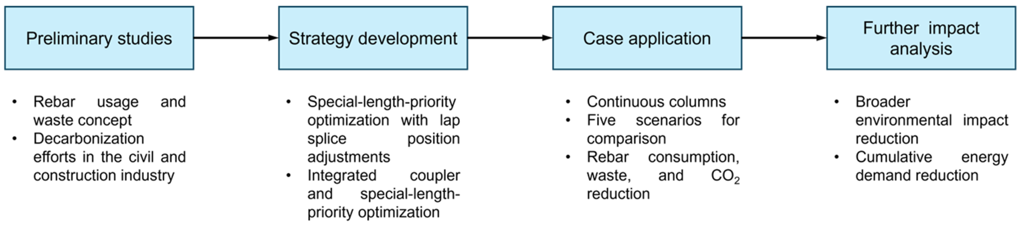
A series of steps are employed to accomplish the study’s objectives, as outlined in Figure 1. These steps encompass preliminary investigations into rebar consumption and waste issues, as well as decarbonization efforts within the industry. The study then introduces the concept of special-length-priority optimization with lap splice position adjustments, integrates the special-length-priority optimization algorithm with couplers, applies the strategy in a case study, and conducts an in-depth analysis of the results. In reinforced concrete (RC) structures, the RC frame is crucial as it bears the majority of loads and forces. Columns, in particular, play a key role in transferring compressive loads from the superstructure to the foundation, requiring more substantial reinforcement to accommodate such requirements. Consequently, this study utilizes columns to illustrate the proposed strategy.
Figure 1.
The proposed strategy development.
3. Related Studies
3.1. Rebar Consumption and Cutting Waste Concept
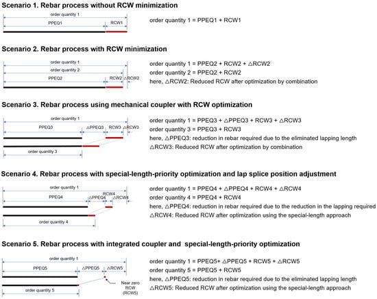
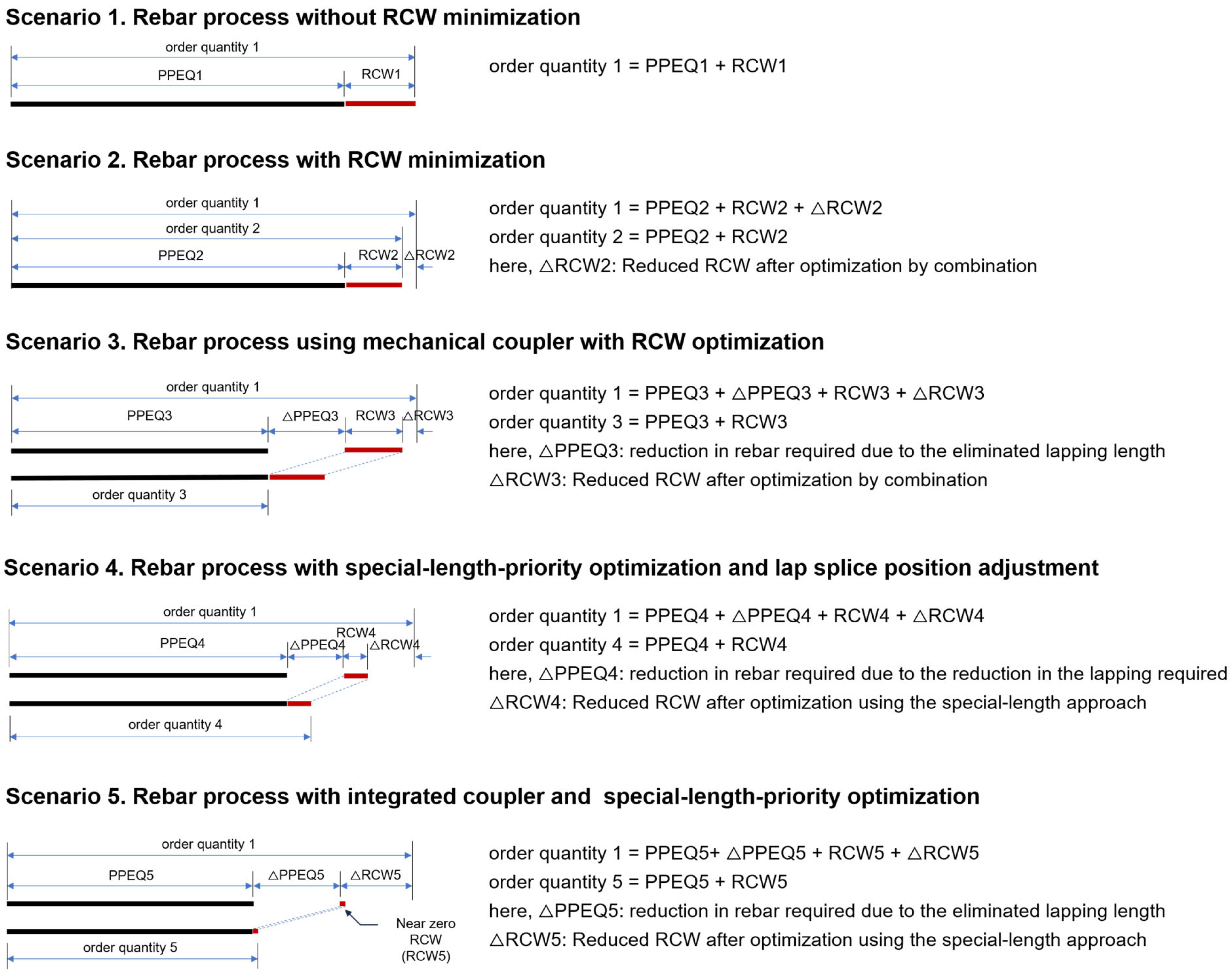
Understanding the terminology and strategic concepts used in this study is essential. “Rebar consumption” or “rebar usage” both refer to the order quantity, encompassing the progress payment eligible quantity (PPEQ) and potential rebar-cutting waste (RCW). The PPEQ represents the actual quantity needed for a specific task, which the client agrees to cover financially. The responsibility for managing rebar-cutting waste and associated losses typically falls on the contractors, who must choose the most efficient strategy to minimize waste and rebar required. Figure 2 presents five example scenarios to further understand the rebar consumption and waste issue in the industry.
Figure 2.
The five scenarios concerning the rebar usage and cutting waste concept.
As demonstrated in Figure 2, the first scenario, which lacks any minimization of rebar-cutting waste (RCW), potentially results in the highest levels of waste generation and rebar consumption. In this case, the required rebar (PPEQ1) directly translates into the purchase of a market-length rebar indicated as order quantity 1 in Figure 2. The second scenario, which has been the focus of most research [5,6], seeks to minimize RCW through optimized cutting patterns but continues to encounter challenges in significantly reducing waste. The RCW minimization yields a reduced order quantity compared to order quantity 1. The third scenario introduces the use of couplers to connect rebar, thereby replacing the traditional lap splicing method. Mechanical couplers connect two rebars, primarily eliminating the need for lap splicing and alleviating bar congestion. Studies highlight their benefits, including reduced rebar waste, improved crack control, enhanced structural integrity, and lower labor costs, while enabling connections between rebars of varying lengths and diameters [4]. This method reduces PPEQ3 (indicated as ΔPPEQ3) by eliminating the need for rebar lapping, although the amount of cutting waste remains considerable. The elimination of rebar lapping further decreases the order quantity, resulting in a lower figure compared to both order quantities 1 and 2. It is important to note that all these scenarios are heavily reliant on the use of a readily available, standard-length rebar. The fourth scenario involves the optimization of special-length rebar usage to decrease both rebar consumption and RCW, incorporating adjustments to lap splice positions as suggested in several studies [3,7]. This approach lowers PPEQ4 (denoted as ΔPPEQ4) by reducing the number of splices required across the structure. The special-length-priority optimization can also be applied to the remaining rebars left for the combination [7]. Typically, building codes dictate lap splice positions, placing them in areas with minimal stress or load to ensure structural integrity, which makes it challenging to reduce rebar usage due to these predetermined positions. However, a study [7] has shown that splicing can occur at any location, provided certain conditions are met, as detailed in the research. Subsequently, the reduction in splices is expected to reduce both rebar consumption and RCW, achieving more efficient consumption over order quantities 1 and 2. Yet, despite this reduction, lap splices are still likely to require more rebar than the mechanical coupler scenario. The fifth scenario pairs the use of couplers with a special-length-priority algorithm to further reduce both rebar consumption and RCW [4]. Similarly to the third case, the use of couplers eliminates the need for rebar splicing, leading to a further reduction in PPEQ5 (referred to as ΔPPEQ5) and a consequent reduction in RCW. Consequently, order quantity 5 significantly decreased relative to the other scenarios. Both the fourth and fifth cases are designed with consideration of continuous structural members and their reinforcements as well as achieving near-zero RCW (<1%) strategy.
3.2. Decarbonization in the Construction Industry
Decarbonization aims to reduce CO2 emissions in sectors like civil engineering to mitigate climate change [10,11], which is associated with natural disasters such as global warming, flooding, and landslides [19]. Strategies in this sector include using sustainable building materials and electric or hybrid equipment during construction to reduce emissions [10,26]. While the development of low-emission materials is complex and resource-intensive, it remains crucial. The carbon emissions associated with products are closely tied to their lifecycle, from raw material extraction to disposal. Minimizing emissions, particularly in rebar, is essential, as the construction phase contributes most to the industry’s carbon intensity. Integrating sustainable building practices can mitigate carbon emissions over the building’s entire lifecycle [26].
According to the World Steel Association [27], steel production reached beyond 1.8 gigatons annually in 2023. Steel manufacturing is highly energy-intensive and follows two main production methods [28]—blast furnace (BF) or basic oxygen furnace (BOF)—with alternative methods of processing steel scrap through an electric arc furnace (EAF) [28]. Studies [16,21,29] found that globally, 63–78.9% of steel is produced using the BF or BOF methods, particularly in Asia, with the remaining 21–36% generated through the EAF method. Both methods emit significant carbon, with BF and BOF relying on coal and coke, while EAF emissions vary based on regional electricity mix sources. This aligns with Rocamora et al.’s investigation [13], which found that steel emissions over its lifecycle range from 1.03 to 3.19 tons of CO2-e per ton of rebar, depending on the energy mix in various lifecycle analysis databases. Another study by Alig et al. [14] reported that rebar in Switzerland, produced via the EAF method, emits 1.6 tons of CO2-e per ton of rebar. In contrast, M25 and M32 concrete emits 0.128 tons and 0.142 tons of CO2-e, respectively, during production [15]. That report [15] also revealed that the carbon emission posed by the rebar is 3.505 tons of CO2-e per ton of rebar. The expected increase in steel demand due to rapid building development makes reducing steel emissions crucial. Strategies like maximizing scrap steel use and promoting short-process steelmaking are effective decarbonization strategies, yet they still involve high-carbon processes, and recycled steel supply falls short of demand [30]. With CO2 levels now at 410 ppm, rising sharply from 300 ppm in the 1950s, urgent action is needed to stabilize concentrations at 450 ppm and mitigate global warming [16].
Decarbonization is intricately connected to the cumulative energy demand (CED), which assesses the total energy consumption of building materials across their lifecycle: from extraction and processing to transportation, construction, and end-of-life stages such as disposal or recycling. The carbon emissions associated with this energy use are influenced by the carbon intensity of the energy sources: fossil fuels result in high carbon emissions, whereas renewable energy sources produce significantly lower emissions. However, the adoption of renewable energy sources remains low, albeit the trend is increasing nowadays. By reducing rebar consumption, demand and production are also lowered, thereby decreasing the CED. This reduction contributes significantly to advancing decarbonization efforts. A study by Alig et al. [14] reported that the production of 1 kg rebar results in a CED of 3.4 kWh oil-eq from non-renewable energy sources and 0.25 kWh oil-eq from renewable energy sources. Implementing effective measures is critical to effectively mitigating carbon emissions, with early reduction in rebar consumption being one of the most feasible solutions given the current circumstances.
4. Strategy Development
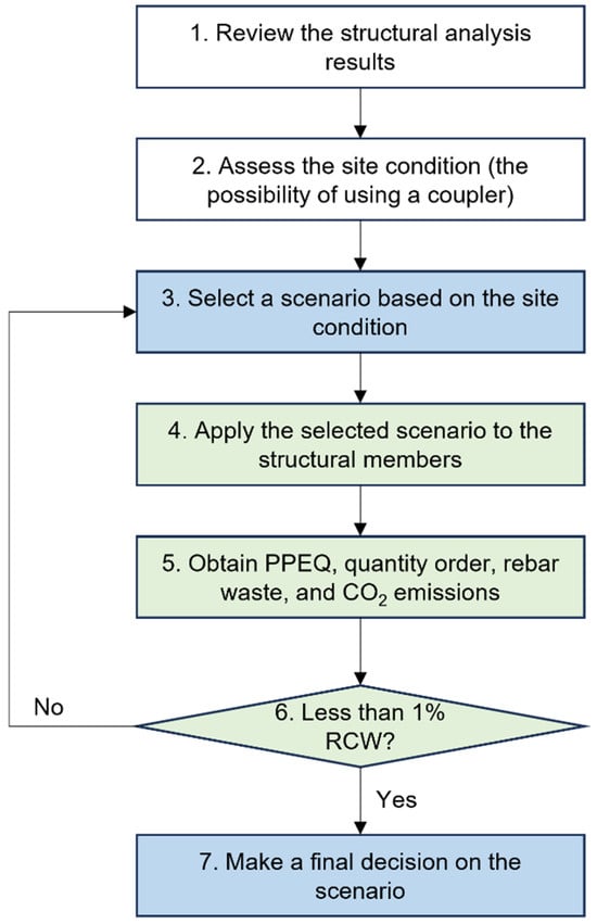
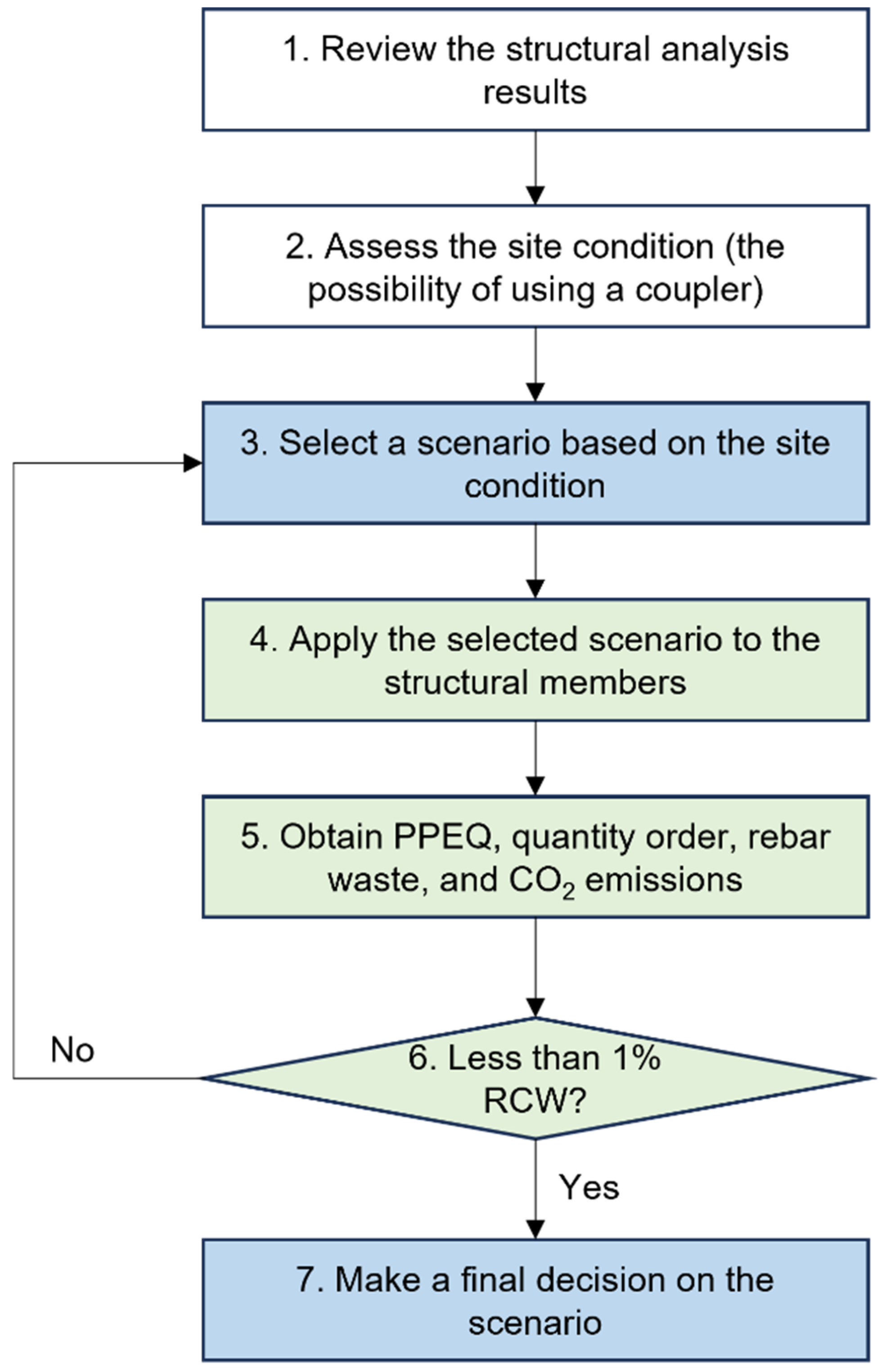
This study presents a comprehensive strategy to support decarbonization in the civil and construction sectors through rebar consumption and cutting waste reduction, analyzed across previously discussed scenarios. Figure 3 illustrates the steps taken to make the final decision based on the findings obtained through the applied scenario.
Figure 3.
Strategy implementation process to minimize rebar consumption.
In reference to Figure 3, a brief explanation of the processes is provided below.
- Review the reinforcement information of the structural members as presented in the structural analysis results.
- Assess the site conditions to determine whether using couplers is feasible. Although previous sections indicate that combining couplers with special-length-priority optimization effectively reduces rebar consumption, lap splices may still be preferred by engineers in smaller to medium-sized projects. This preference arises because the couplers may require adjustments in design and changes to the reinforcement layout, which may not be favorable in smaller projects.
- Based on the site conditions, select the appropriate scenario, either using conventional lap splices or coupler variations.
- Apply the selected scenario to the relevant structural members, considering that a building typically consists of columns, beams, and slabs, each with distinct characteristics and roles within the structural system.
- Based on the application of the selected scenarios, obtain the PPEQ, order quantity, cutting waste, and carbon emissions.
- Verify whether the obtained cutting waste is less than 1%. Cutting waste below 1% is critical due to its strong connection to rebar consumption, which significantly reduces overall consumption. Various studies [3,7] indicate that reducing the number of splices contributes to this reduction. If the waste exceeds 1%, another scenario should be selected and re-evaluated.
- If the obtained cutting waste is less than 1%, the selected scenario can be confirmed as the final decision.
Additionally, this section elaborates on the details of all scenarios discussed in the previous section.
4.1. Scenarios 1–3: Rebar Processes with and Without Cutting Waste Minimization and Coupler–Cutting Waste Minimization Combination
As discussed earlier, Scenarios 1 through 3 utilize standard or market-length rebar, which typically ranges from 6 to 10 m in 1 m increments. The conventional approach for connecting rebar is to connect the bars at each floor level. In Scenario 1, where no rebar-cutting waste minimization is applied, the required length of column rebar on each floor is determined by summing the floor height with the lapping length. The corresponding order length is then determined based on this required length. For instance, if the necessary rebar length is 5.5 m, a 6 m rebar will be ordered. The PPEQ1 and order quantity 1 are calculated by multiplying the rebar’s unit weight by the number of required rebars and by the required and ordered lengths, respectively. Scenario 2 focuses on minimizing rebar-cutting waste. The required rebar lengths are determined in the same manner as in Scenario 1. However, these lengths are then combined and optimized using a minimization algorithm to identify order lengths that produce the least amount of waste (RCW2). PPEQ2 and order quantity 2 are calculated by multiplying the rebar’s unit weight by both the number of required rebars and the required and optimized order lengths. Scenario 3 introduces the use of couplers in place of rebar lapping, along with rebar-cutting waste minimization. Here, the required rebar length for each floor is determined by subtracting half of the coupler’s inner gap from the floor height. These lengths are similarly combined and optimized using a minimization algorithm to achieve order lengths that generate the lowest possible waste (RCW3). As with Scenario 2, PPEQ3 and order quantity 3 are calculated by multiplying the rebar’s unit weight by the number of required rebars and the optimized order lengths.
4.2. Scenario 4: Rebar Processes with Special-Length-Priority Optimization and Lap Splice Position Adjustment
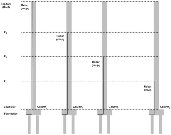
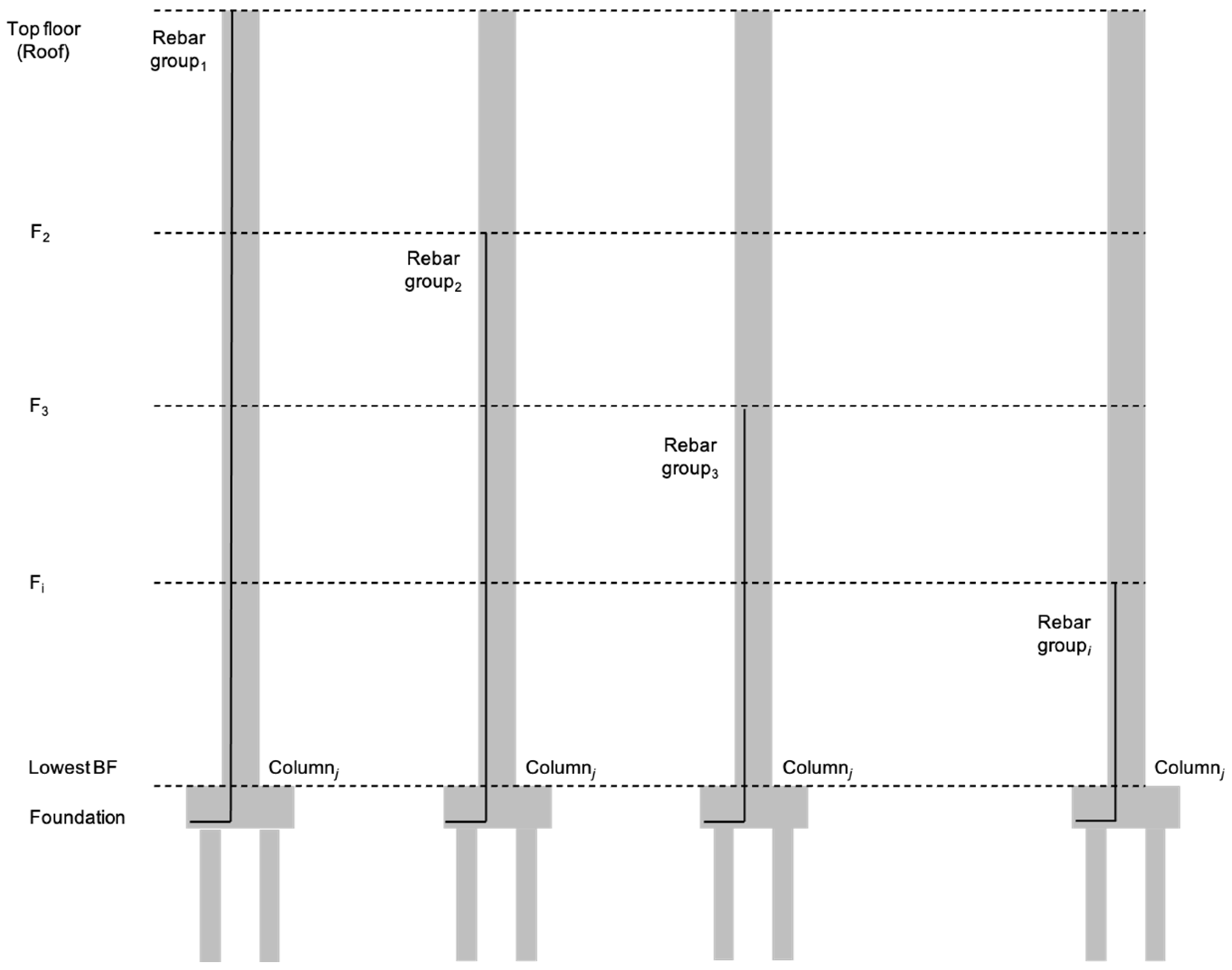
Following the structural analysis and design stage, the generated results were utilized to optimize the rebar consumption, encompassing factors such as length, quantity, and lap splice positions. The optimization process employs an approach previously developed in an earlier study [7]. As discussed earlier, columns were selected as the focal point for the case application. Given the interconnected nature of columns extending continuously from the foundation to the top floor, rather than treating them as discrete, individual members, the rebar layout was categorized into groups based on length similarities. In contrast, the existing approaches depicted in Scenarios 1–3 treat columns as individual elements, typically resulting in rebar laps at each floor level. The proposed strategy introduces flexibility by allowing adjustments to lap splice positions, enabling rebar laps to occur at any location along the structure, thus optimizing material use and reducing waste. This categorization is illustrated in Figure 4, where certain rebars extend to specific floors (e.g., F2, F3, Fi) from the foundation. The quantity of rebars in each group was determined by the total rebar amount extending from the foundation to the top, as indicated by the structural analysis outcomes. For instance, if twelve rebars extend from the foundation to the top floor (rebar group 1), the number of rebars in subsequent groups decreases accordingly, reflecting the number of rebars that extend only up to certain floors. However, in some instances, the number of rebars in subsequent groups may increase due to specific building requirements and load conditions. The study utilizes a series of Equations (1) through (8). Equation (1) calculates the total length for each rebar group. Equation (2) governs the bending deduction due to rebar bending based on the shape code. Following this, Equation (3) determines the number of special-length rebars for the first group, and Equation (4) calculates the number of splices considering the special lengths. Equation (5) evaluates the reduction in splices by comparing the original and new values, leading to the recalculation of the total rebar length in Equation (6). Equations (7) and (8) are used to obtain the special rebar lengths. Initially, Equations (1) through (8) are applied to address the first group of continuous rebars. For subsequent rebar groups that extend from the foundation to specific levels, Equations (1)–(6) are employed to calculate the reduced total rebar length by factoring in the decrease in the number of splices. The special length identified in Equation (8) is then assigned to the remaining column rebar groups. Equations (9) and (10) are used to determine the number of rebars within these groups, including the special-length rebars. Given that applying the previously identified special lengths to other rebar groups may result in remaining rebars of varying lengths, Equation (11) is used to calculate these remaining lengths. Further optimization procedures are detailed in the previous study [7].
where is the total length of continuous main rebar, is the height of each floor (mm), is the number of floors for each rebar group, is the depth of the girder, is the length of the dowel bar, is the hook anchorage length, is the total lap splice length, is the number of splices, is the bending deduction, is the rebar’s specified bend radius, is the diameter of the rebar, is the number of special-length rebar, is the maximum purchase length, is the number of splices considering the special-length rebar, is the difference between the new number of splices and the original number of splices (), is the new total rebar length, is the rebar lapping length, is the calculated rebar length, is the identified special-length rebar, is the number of rebar in that rebar group, is the number of previously identified special-length rebar in that rebar group, and is the length of the remaining rebar.
Figure 4.
Rebar categorization into several distinct groups.
The rebar-cutting waste (RCW), required quantity (PPEQ), and order quantity are derived using the equations outlined below. Equation (12) calculates the required quantity of continuous rebars () based on the rebar length obtained from Equation (7). For the remaining rebars, their quantity () is determined by considering the total length of the cutting pattern I (), as described in Equation (13). The total required rebar quantity (PPEQ) is then the sum of the quantities from both continuous and remaining rebars, as presented in Equation (14). To calculate the total order quantity which is composed of the order quantity for both continuous and remaining rebars considering the identified special-length rebar, Equation (15) is used. Rebar-cutting waste (RCW), defined as the relative difference between the required and ordered quantities divided by the ordered quantity, can be calculated using Equation (16).
4.3. Scenario 5: Rebar Processes with Integrated Coupler and Special-Length-Priority Optimization
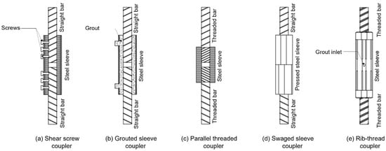
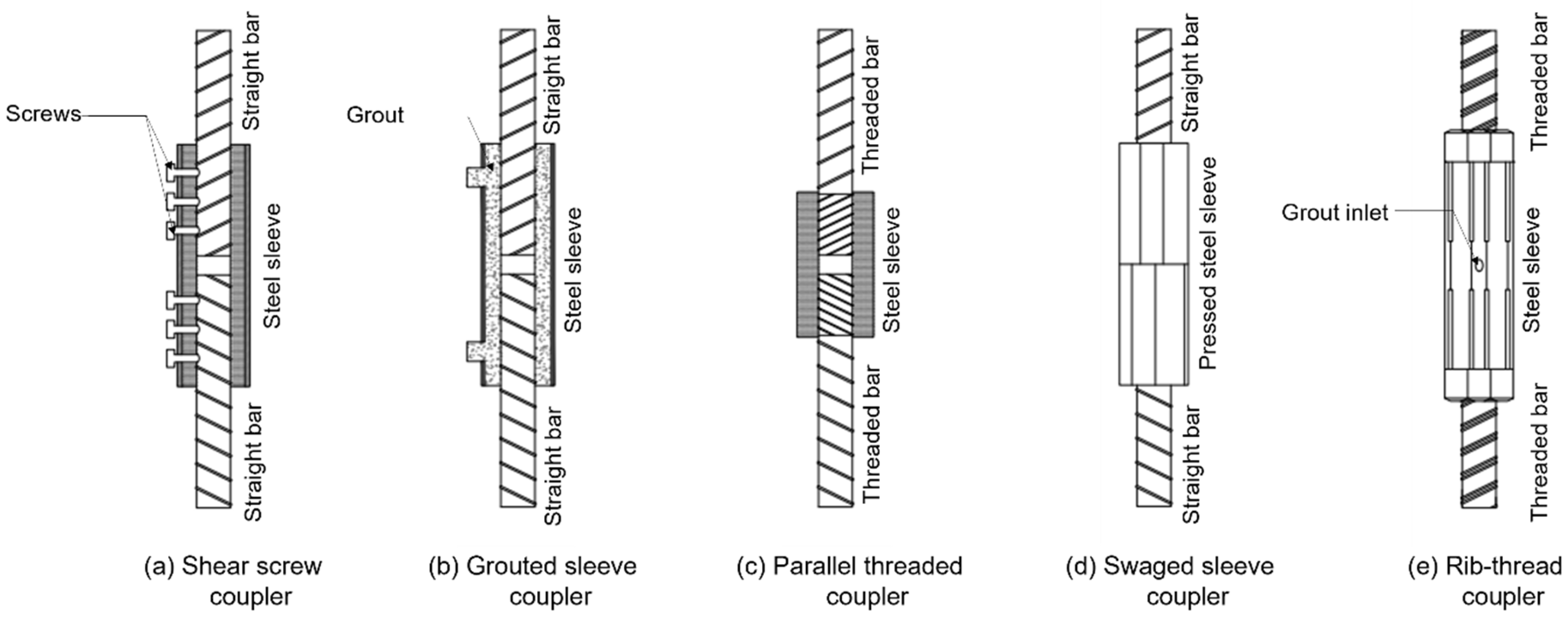
The steps outlined in this subsection closely resemble those in the previous one, with the key distinction being the integration of couplers instead of lap splicing for rebar connection. The outputs from the structural analysis and design stage, which provide the geometric and reinforcement details of the members, were used to optimize rebar consumption. Several types of couplers, illustrated in Figure 5, are available on the market. These include parallel threaded couplers (PTCs), grouted sleeve couplers (GSCs), shear screwed couplers (SSCs), swaged sleeve couplers (SSCs), and rib thread couplers (RTCs), each exhibiting different characteristics and performance when subjected to lateral forces.
Figure 5.
Various types of couplers available in the market (Source: [4]).
While the performance of these couplers is generally comparable, their ease of installation varies. Parallel threaded couplers (PTCs) are relatively simple to install, as they only require threading the ends of the rebar and screwing the coupler onto them. Rib thread couplers (RTCs) are similar to PTCs; however, the ribbed design may slightly complicate the installation process. Grouted sleeve couplers (GSCs) involve filling the sleeve with grout to bond the rebar; however, this process requires additional steps and curing time. Both shear screwed couplers (SSCs) and swaged sleeve couplers (SSCs) require specialized tools for installation. Swaged sleeve couplers need a compressive force to crimp the coupler onto the rebar, while shear screwed couplers require precise alignment of the screws to ensure proper connection of the rebars. That being said, engineers should carefully evaluate the selection of the most appropriate coupler type, considering specific site conditions, project requirements, and ease of installation.
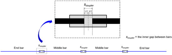
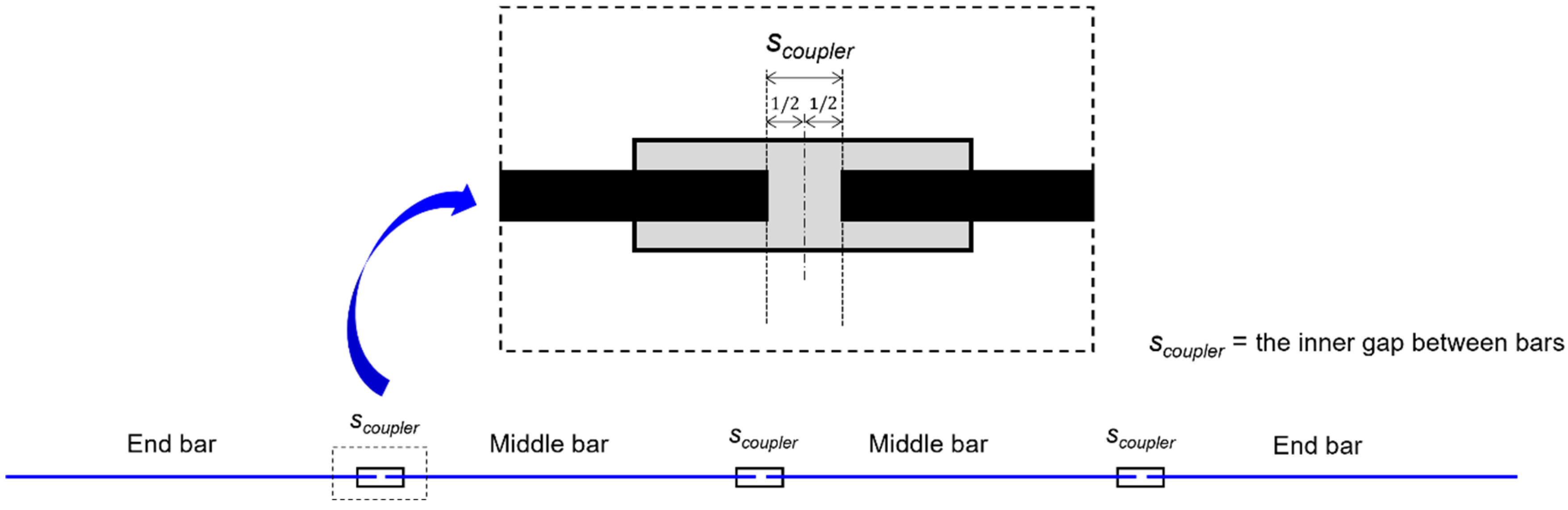
As mentioned earlier, the key difference between this approach and the previous one is the integration of couplers in the calculation, represented by the inner spacing of the coupler, as shown in Figure 6. The inner gap of the couplers influences the calculation of the special lengths, as demonstrated in the set of equations below. As a result, the inclusion of the coupler lead plays a role in the classification of end and middle bars, as illustrated in Figure 6, which shows the position of the coupler between the connected adjacent rebars.
Figure 6.
A coupler’s inner gap illustration (adapted and modified from [4]).
This study employs a set of Equations (17) through (25), as proposed in a previous study [4]. Equation (17) is used to determine the total length for each rebar group. Following this, Equation (3) calculates the number of special-length rebars for the first group, while Equation (18) computes the number of couplers needed to connect the rebars, taking the special-length rebar into account. Equations (19)–(21) are applied to obtain the special rebar lengths, considering that the coupler may affect both the middle and end bars, as illustrated in Figure 6. For subsequent rebar groups that extend from the foundation to specific levels, Equations (2) and (17) are employed to calculate the total rebar length. The special lengths identified in Equations (19) and (20) are then assigned to the remaining column rebar groups. Equations (22)–(24) are used to determine the number of rebars within these groups, including the special-length rebars and the number of couplers. It is crucial to recognize that using these special lengths in other rebar groups may result in rebars of varying lengths. The remaining lengths can be calculated using Equation (25). The rebar-cutting waste (RCW), required quantity (PPEQ), and order quantity are derived using the equations previously outlined in Equations (12)–(16).
where is the total length of continuous main rebar, is the height of each floor (mm), is the number of floors for each rebar group, is the depth of the girder, is the length of the dowel bar, is the hook anchorage length, is the bending deduction, is the rebar’s specified bend radius, is the diameter of the rebar, is the number of couplers, is the inner gap of the coupler, is the calculated rebar length, is the identified special-length rebar, is the number of rebar in that rebar group, is the number of previously identified special-length rebar in that rebar group, and is the length of the remaining rebar.
5. Case Application
The implementation process described in the previous section was carried out, with site conditions assumed to support the use of both lap splices and couplers. All five scenarios were applied to the selected case study subject and compared to demonstrate the strategy’s effectiveness. The 32 continuous columns were selected from an RC mixed-use high-rise building. Rebar grade 600, which has a yield strength of 600 MPa, was used for rebars larger than 16 mm, while 500 MPa was used for rebars smaller than 16 mm. The structural design and information were checked with the relevant building codes, and rebar details were adopted from the reports. The selected building comprised 23 floors, including two underground basements, with a height of 5.4 m. The standard, minimum, and maximum floor heights were 3.8 m, 3.25 m, and 6.3 m, respectively. The selected continuous column was reinforced with 25 mm longitudinal rebars and 10 mm of hoops. M30 concrete was used for the entire floor. The size of the column decreased on higher floors. The detailed column and its reinforcement arrangement are presented in Appendix A, Table A1. Based on the arrangement, the main rebars of similar lengths were divided into nine groups: B2F–Rooftop, B2F–F15, B2F–F14, B2F–F12, B2F–F10, B2F–F8, B2F–F6, B2F–F4 and B2F–F2. The attributes of the continuous column and its reinforcements are presented in Table 1. Refer to Figure 4 for the visualization of the rebar group division. A more detailed building’s floor height information can be found in Appendix A, Table A2.
Table 1.
Case study building’s attributes of the continuous column and its reinforcements.
This study focuses on the adoption of improved rib thread couplers (RTCs), which feature a cylindrical sleeve with threaded ends designed to securely attach rebar ends, fastened with nuts (see Figure A1 in Appendix B). The assembly is subsequently filled with grouting material to strengthen the connection between rebars. The specifications and dimensions for the RTC provided by a specific manufacturer [31] are detailed in Table A3. As shown in Figure A1, a gap exists between the threads of the RTC and the threaded rebar, typically measuring 20 mm for rebar sizes D16 to D29 and 30 mm for sizes exceeding D32. The coupler accommodates a permissible tolerance regarding the length of rebar inserted in the center, which facilitates a reliable connection, even when threaded rebars have cutting inaccuracies. In this study, threaded rib rebars from the same manufacturer (Tokyo Tekko, Co., Ltd., Tokyo, Japan) [32] were utilized, with unit weights of 3.98 kg/m for D25 rebar size. This section is organized into several parts: the calculation of quantities, waste, and carbon emission, the comparison of quantity differences across scenarios, the further assessment of the environmental impact caused by rebar, and the strategic selection of the optimal scenario.
5.1. Rebar Consumption and Waste Generation
It is important to note that the standard rebar lengths available in the market include 6, 7, 7.5, 8, 9, 10, and 11 m. However, special-length rebar can be ordered in lengths ranging from 6 to 12 m, with increments of 0.1 m, as the maximum available rebar length is 12 m. Ordering special-length rebar typically requires a minimum order of 50 tons and must be placed at least two months in advance, although these conditions are temporarily disregarded for this analysis. The special-length-priority optimization method was applied to generate less than 1% waste. After applying all scenarios discussed earlier, the quantities and associated waste are summarized in Table 2. Additionally, carbon emissions were calculated and are presented in Table 2. Research on the lifecycle assessment of steel rebar production shows a wide range of emission values depending on energy sources and production methods. According to Ghayeb et al. [15], steel rebar emits 3.505 tons of CO2-e per ton. In comparison, each D25 coupler produces 8.6 kg of CO2-e [15]. These figures are adopted for the calculations in this study.
Table 2.
Rebar quantities, waste, and carbon emissions generated in all scenarios.
As shown in Table 2, the results highlight the inefficiencies inherent in conventional rebar practices, particularly the reliance on market-length rebar combined with conventional lap splicing, as exemplified by Scenario 1. This scenario represents the least sustainable approach, yielding the highest levels of rebar consumption and cutting waste, with waste accounting for a notable percentage of total rebar usage. Scenario 2 demonstrates modest improvements through waste minimization techniques, yet these strategies remain limited by the constraints of market-length rebar, leaving significant inefficiencies unresolved. The incorporation of couplers in Scenario 3 marks a significant advancement, resulting in notable reductions in rebar usage and cutting waste compared to the preceding scenarios. Nonetheless, a waste rate exceeding 3% emphasizes the need for further minimization. Scenarios 4 and 5 showcase the transformative impact of integrating special-length-priority optimization. Scenario 4 achieves a significant reduction in waste to below 1% by adjusting lap splice positions, while Scenario 5, which combines this optimization with coupler integration, delivers the highest overall efficiency. This scenario minimizes waste to an almost negligible level and substantially reduces carbon emissions, positioning it as the most effective strategy for sustainable construction practices. A detailed comparison of these improvements, including waste minimization and emissions reductions, is provided in Table 3.
Table 3.
Comparison of rebar consumption, waste, and emissions reductions across scenarios relative to Scenario 1.
Table 3 further reveals that Scenario 5 delivers the most comprehensive advancements across all evaluated parameters, highlighting its effectiveness in improving both material efficiency and environmental performance. By integrating couplers with the special-length-priority algorithm, this approach achieves significant reductions in PPEQ, ordered rebar quantities, cutting waste, and carbon emissions, while maintaining a waste rate below 1%, an essential benchmark for sustainability. Scenario 4, which combines special-length-priority optimization with lap splice position adjustments, emerges as the second most effective strategy, as indicated in Table 2. Despite achieving slightly lower reductions in certain metrics compared to Scenario 3, its ability to maintain a waste rate below 1% makes it a more practical strategy for decarbonization efforts. Scenario 3, while demonstrating significant potential, is undermined by its reliance on market-length rebars, resulting in a waste rate exceeding 1% and limiting its overall effectiveness. These findings emphasize the necessity of transitioning from conventional rebar practices to unlock the full benefits of advanced rebar consumption and waste minimization strategies. While all scenarios surpass the baseline performance of Scenario 1, Scenario 5 emerges as the most effective, offering a scalable and impactful solution for reducing rebar consumption, rebar waste, and associated emissions in the civil and construction industry. Section 5.3 provides further insights into the selection criteria for the optimal strategy.
5.2. Environmental Impact Analysis of Rebar Consumption
Beyond carbon emissions, significant rebar consumption impacts various environmental metrics critical to decarbonization, including water footprints, global warming potential (GWP), abiotic depletion potential (ADP), acidification potential (AP), and cumulative energy demand (CED). The blue water footprint measures freshwater use in steel rebar production, while the gray water footprint reflects the water needed to dilute pollutants before entering natural water bodies. A study [33] found that the production of 1 ton steel rebar in China requires 5.47 m3 of water and discharges 145.74 m3 of gray water. Reducing rebar consumption directly decreases production demand and associated energy use, lowering carbon emissions from water extraction, treatment, and wastewater management. GWP evaluates the heat retention potential of greenhouse gases, emphasizing the importance of minimizing reliance on carbon-intensive materials to combat climate change. ADP assesses the depletion of non-renewable resources like minerals and fossil fuels, upon which the construction industry heavily relies, including steel rebar production. Decreasing the use of virgin materials in rebar production aligns with sustainability goals by lessening reliance on finite resources and non-renewable energy. AP assesses the acidification potential impact of pollutants, such as sulfur dioxide and nitrogen oxides, often linked to fossil fuel combustion and industrial activities. Park et al. [34] found that each kg of rebar waste generates 0.35 kg CO2-eq GWP, 2.79 × 10⁻³ kg Sb ADP, and 2.31 × 10⁻³ kg SO2-eq AP. Since blast furnaces and basic oxygen furnace methods remain dominant [16,21,29] and are carbon-intensive, reducing AP through optimized rebar consumption can promote cleaner energy and production practices. High CED from non-renewable energy correlates with increased carbon emissions and GWP, highlighting the need to reduce rebar consumption to mitigate environmental impacts. Table 4 summarizes metrics associated with rebar consumption and decarbonization, with water footprints and CED linked to consumption levels and GWP, ADP, and AP tied to waste generated as shown in Table 2.
Table 4.
Environmental impact metrics related to rebar consumption and decarbonization.
Table 4 reveals the critical role of optimizing rebar consumption and minimizing cutting waste since such reductions directly correspond to lower environmental impacts. Among the evaluated scenarios, Scenario 5 emerges as the most sustainable approach, effectively integrating couplers with the special-length-priority algorithm. This strategy significantly reduces environmental impacts, particularly in terms of water footprints (blue water and gray water), CED for non-renewable resources, GWP, ADP, and AP. Scenario 4, while effective, demonstrates slightly lower performance due to the adoption of lap splice adjustments, indicating that further integration of advanced methods is necessary to achieve maximum efficiency. Conversely, the continued reliance on conventional methods and market-length rebar poses a significant challenge to decarbonization efforts as evidenced in Scenarios 1 to 3. In conclusion, these findings further solidify the effectiveness of special-length-priority optimization and coupler integration in advancing decarbonization in the industry.
5.3. Strategic Selection of the Optimal Scenario
The findings presented above emphasize the effectiveness of the special-length-priority optimization strategy, particularly when combined with either lap splice position adjustments or couplers, as demonstrated in Scenarios 4 and 5, respectively. However, the adoption of couplers is still not widespread due to concerns over pre-planning, costs, installation time, and constructability, especially when fabrication and assembly processes are not well-coordinated. The long-standing use, simplicity, and low cost of lap splicing contribute to engineers’ hesitance to switch to couplers. Moreover, the variety of coupler types available, each tailored to specific site conditions, seismic performance requirements, and rebar characteristics, can further overwhelm engineers. Rebar itself falls into two main categories, deformed and threaded bars, each requiring a specific coupler type. Nevertheless, a study [35] analyzing various coupler systems from a sustainability perspective found that threaded couplers when paired with threaded rebar outperform lap splices in terms of labor productivity, project duration, and cost. That said, any transition to couplers should consider local regulations and project-specific requirements. Based on the previously discussed results and these findings, Scenario 5 is strongly recommended for new building projects wherever feasible. If Scenario 5 is not viable, Scenario 4 is recommended as the next best strategy.
6. Discussions
Since the onset of the industrial revolution, the construction industry has posed considerable environmental challenges. In 2013, buildings accounted for 30% of global energy consumption and were responsible for 25% of total CO2 emissions. Additionally, the sector generated approximately 75% of the world’s waste [36]. Another study revealed a higher consumption of 39% in the building sector and related construction activities, with operational carbon emissions accounting for 28% and building materials for 11% [26]. Since this current research focuses on construction and material usage, reducing material consumption is critical. The findings discussed in the previous section emphasize that integrating special-length-priority minimization with lap splice adjustments and couplers aligns with green construction goals, a key strategy for reducing carbon emissions. Green construction promotes resource conservation and environmental protection through efficient management and technology while maintaining quality and safety, focusing on energy, land, water, and material savings, unlike conventional projects which prioritize cost, quality, and schedule [26]. Nonetheless, further decarbonization efforts are deemed necessary to meet the objectives of the Paris Climate Agreement, COP 26 and 28, and the Sustainable Development Goals (SDGs) to combat the impacts of climate change.
6.1. Further Decarbonization Effort
The rapid expansion of the construction industry contributes to global economic growth while exerting a considerable impact on both natural and built environments. The sector demands large quantities of energy, natural resources, and water while generating extensive waste, with RC structures being a notable contributor [26]. Steel rebar, a critical element of reinforced concrete (RC), is manufactured through various carbon-intensive methods. Numerous studies [11,16,17,29,37,38] have explored potential strategies for decarbonizing the construction industry, focusing on two main approaches: decarbonizing production processes and creating products with lower environmental impacts. Research [11,17,29] indicates that the best available strategies for transitioning to carbon-lean or carbon-free steel production include hydrogen direct reduction (H-DR), which utilizes 100% H2 instead of natural gas, electrowinning powered by renewable energy, and the use of biomass or syngas as a fuel and reducing agent instead of coke. Another breakthrough technology also suggested to achieve further reductions is carbon capture and storage (CCS) or carbon capture, utilization, and storage (CCUS) [11,16,17,29,37,38]. CCS captures CO2 emissions from industrial processes, such as steel production, before they are released into the atmosphere. The captured CO2 is then transported and stored underground to mitigate its contribution to global warming. In contrast, CCUS extends this concept by not only capturing and storing CO2 but also finding ways to utilize it in various industrial applications, such as fuels and chemicals. By transforming CO2 from a waste product into a valuable resource, both technologies play a crucial role in fully decarbonizing the sector. Nevertheless, using the best available technologies in existing integrated steel plants, along with efficient heat recovery, integrated energy flow management, and the adoption of CCS/CCUS from off-gases, can reduce related emissions by 40–50% [16]. Fiber-reinforced polymer (FRP) rebar has emerged as a viable alternative to conventional steel due to its ability to substantially reduce CO2 emissions. Various types of FRP rebars, such as carbon fiber-reinforced polymer (CFRP), basalt fiber-reinforced polymer (BFRP), and glass fiber-reinforced polymer (GFRP), offer differing levels of emissions reduction: 4–40% for CFRP, 38–75% for BFRP, and 22.8–43% for GFRP when compared to traditional steel [11]. Integrating these rebar types with the proposed optimization strategy could further enhance CO2 reductions, significantly contributing to decarbonization and carbon neutrality goals.
6.2. Challenges and Future Research
The findings highlight the effectiveness of the proposed strategy in reducing rebar consumption, which, in turn, lowers carbon emissions and supports decarbonization in the civil and construction industry. However, several challenges impede the widespread adoption of this strategy. Economic costs, time constraints, lack of educational awareness, and inadequate policy support are significant barriers to decarbonization efforts [26]. For instance, the use of couplers necessitates substantial initial investment in terms of cost, labor, and time, as a well-organized implementation plan is essential. Additionally, the use of special-length rebar remains limited due to insufficient promotion. Generally, the implementation of this strategy and green construction technologies is more costly, complex, and time-consuming due to stricter requirements. A lack of awareness among professionals and limited support from policymakers further hinder progress, which may lead engineers to revert to the more traditional and simpler method of lap splicing. This study primarily addresses pre-construction planning to optimize rebar consumption. Future research should explore how these strategies can be effectively applied on actual construction sites, such as through an auxiliary device that can be used to assist the special-length rebar installation when multiple building components are involved. Additionally, research could focus on designing educational programs and training initiatives aimed at increasing awareness of green construction practices and decarbonization efforts. Another important area of study would be examining the impact of government policies, incentives, and regulations in promoting decarbonization within the construction industry.
7. Conclusions
This study proposed a comprehensive strategy aimed at supporting decarbonization in the civil and construction industry by minimizing rebar consumption. The proposed strategy integrates a special-length-priority minimization algorithm with lap splice position adjustments or couplers to reduce rebar consumption, waste, and carbon emissions. The key findings led to the following conclusions.
- Conventional rebar practices, including the use of market-length and conventional lap splicing, contribute significantly to excessive rebar consumption and waste generation, impeding decarbonization efforts.
- The use of couplers substantially reduces the quantity of ordered and consumed rebar. However, when combined with market-length rebar, some inefficiencies remain, particularly regarding cutting waste. This waste leads to substantial carbon emissions and environmental impact.
- The integration of special-length-priority optimization with lap splice position adjustments leads to notable reductions in rebar consumption and waste while maintaining a minimal cutting waste rate. This strategy proves to be one of the most effective approaches for reducing environmental impacts.
- The strategy incorporating both special-length-priority optimization and couplers achieves the greatest reductions in rebar consumption, waste, carbon emissions, and associated environmental impacts, positioning it as the most effective and efficient strategy for future construction projects.
- Based on the results and findings, it is recommended that the industry prioritize this strategy, particularly where viable. Should this strategy not be viable, the integration of special-length-priority with lap splice position adjustments serves as the next best alternative.
The findings of this study highlight the importance of ongoing efforts to develop and apply innovative approaches aimed at reducing rebar consumption and carbon emissions within the construction industry. Future research should focus on evaluating the feasibility of incorporating these strategies across various construction settings to maximize their contributions to decarbonization and environmental sustainability.
Author Contributions
Conceptualization, S.K.; methodology, D.D.W., T.S.N.R. and S.K.; validation, D.D.W., T.S.N.R. and S.K.; formal analysis, D.D.W. and T.S.N.R.; investigation, D.D.W. and T.S.N.R.; resources, S.K.; data curation, S.K.; writing—original draft preparation, D.D.W. and T.S.N.R.; writing—review and editing, D.D.W., T.S.N.R. and S.K.; supervision, S.K.; project administration, S.K.; funding acquisition, S.K. All authors have read and agreed to the published version of the manuscript.
Funding
This work was supported by the National Research Foundation of Korea (NRF) grant funded by the Government of the Republic of Korea (MOE) [No. 2022R1A2C2005276].
Data Availability Statement
Data sharing is applicable upon reasonable request.
Conflicts of Interest
Author Sunkuk Kim is employed by the company Earth Turbine Co., Ltd. The remaining authors declare the research was conducted in the absence of any commercial or financial relationships that could be interpreted as a potential conflict of interest.
Appendix A
Table A1.
Rebar layout and arrangement of the continuous columns.
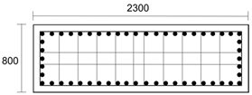
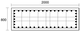
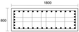
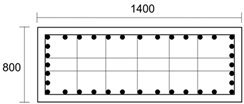
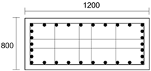
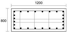
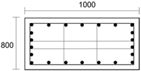
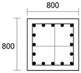
Table A2.
A detailed building’s floor height.
Appendix B
Figure A1.
Details of a rib thread coupler (RTC) [30].
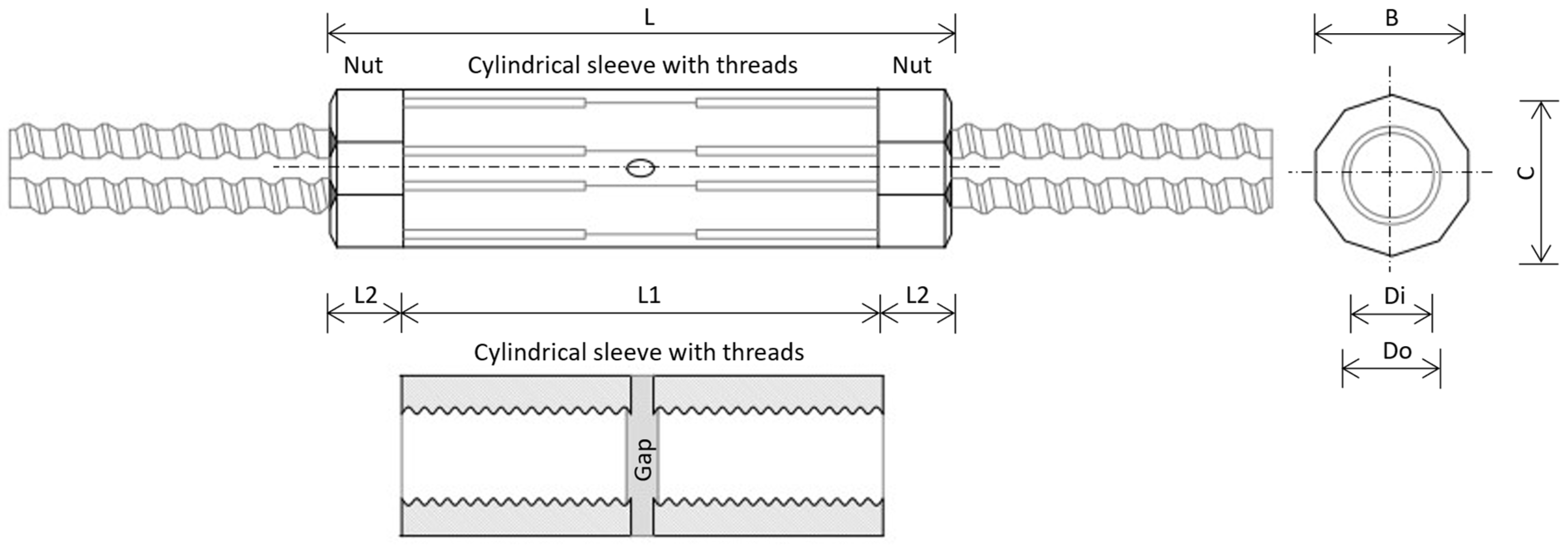
Table A3.
Available rib thread coupler specifications (in mm) [30].
References
- Swilling, M.; Hajer, M.; Baynes, T.; Bergesen, J.; Labbé, F.; Musango, J.K.; Ramaswami, A.; Robinson, B.; Salat, S.; Suh, S.; et al. The Weight of Cities: Resource Requirements of Future Urbanization; International Resource Panel; United Nations Environment Programme: Nairobi, Kenya, 2018. [Google Scholar]
- Habert, G.; Miller, S.A.; John, V.M.; Provis, J.L.; Favier, A.; Horvath, A.; Scrivener, K.L. Environmental Impacts and Decarbonization Strategies in the Cement and Concrete Industries. Nat. Rev. Earth Environ. 2020, 1, 559–573. [Google Scholar] [CrossRef] [Scilit]
- Widjaja, D.D.; Kim, S. Reducing Rebar Cutting Waste and Rebar Usage of Beams: A Two-Stage Optimization Algorithm. Buildings 2023, 13, 2279. [Google Scholar] [CrossRef] [Scilit]
- Widjaja, D.D.; Kim, S.; Kim, D.-J. Optimizing Rebar Consumption and Cutting Waste in Column Reinforcement: Integrated Mechanical Couplers and a Special-Length-Priority Minimization Algorithm. Buildings 2024, 14, 287. [Google Scholar] [CrossRef] [Scilit]
- Khondoker, M.T.H. Automated Reinforcement Trim Waste Optimization in RC Frame Structures Using Building Information Modeling and Mixed-Integer Linear Programming. Autom. Constr. 2021, 124, 103599. [Google Scholar] [CrossRef] [Scilit]
- Zheng, C.; Yi, C.; Lu, M. Integrated Optimization of Rebar Detailing Design and Installation Planning for Waste Reduction and Productivity Improvement. Autom. Constr. 2019, 101, 32–47. [Google Scholar] [CrossRef] [Scilit]
- Widjaja, D.D.; Rachmawati, T.S.N.; Kim, S.; Lee, S. An Algorithm to Minimize Near-Zero Rebar-Cutting Waste and Rebar Usage of Columns. Sustainability 2023, 16, 308. [Google Scholar] [CrossRef] [Scilit]
- Widjaja, D.D.; Khant, L.P.; Kim, S.; Kim, K.Y. Optimization of Rebar Usage and Sustainability Based on Special-Length Priority: A Case Study of Mechanical Couplers in Diaphragm Walls. Sustainability 2024, 16, 1213. [Google Scholar] [CrossRef] [Scilit]
- Locke, J.; Dsilva, J.; Zarmukhambetova, S. Decarbonization Strategies in the UAE Built Environment: An Evidence-Based Analysis Using COP26 and COP27 Recommendations. Sustainability 2023, 15, 11603. [Google Scholar] [CrossRef] [Scilit]
- Paneru, S.; Suh, S.; Seo, W.; Rausch, C. Evaluating the Decarbonization Potential of Industrialized Construction: A Review of the Current State, Opportunities, and Challenges. J. Constr. Eng. Manag. 2024, 150, 03124005. [Google Scholar] [CrossRef] [Scilit]
- Sbahieh, S.; Zaher Serdar, M.; Al-Ghamdi, S.G. Decarbonization Strategies of Building Materials Used in the Construction Industry. Mater. Today Proc. 2023, S2214785323046163. [Google Scholar] [CrossRef] [Scilit]
- Kim, K.; Jeon, Y.; Park, Y.-J.; Park, S. Sustainable Anti-Tank Obstacle System Applying Civil–Military Cooperation in Highly Urbanized Areas. Sustainability 2022, 14, 12715. [Google Scholar] [CrossRef] [Scilit]
- Martínez-Rocamora, A.; Solís-Guzmán, J.; Marrero, M. LCA Databases Focused on Construction Materials: A Review. Renew. Sustain. Energy Rev. 2016, 58, 565–573. [Google Scholar] [CrossRef] [Scilit]
- Alig, M.; Frischknecht, R.; Krebs, L.; Ramseier, L.; Stolz, P. LCA of Climate Friendly Construction Materials; Final Report v2.0; Treeze Ltd.: Uster, Switzerland, 2020. [Google Scholar]
- Ghayeb, H.H.; Razak, H.A.; Sulong, N.H.R. Evaluation of the CO2 Emissions of an Innovative Composite Precast Concrete Structure Building Frame. J. Clean. Prod. 2020, 242, 118567. [Google Scholar] [CrossRef] [Scilit]
- Holappa, L. A General Vision for Reduction of Energy Consumption and CO2 Emissions from the Steel Industry. Metals 2020, 10, 1117. [Google Scholar] [CrossRef] [Scilit]
- Muslemani, H.; Liang, X.; Kaesehage, K.; Ascui, F.; Wilson, J. Opportunities and Challenges for Decarbonizing Steel Production by Creating Markets for ‘Green Steel’ Products. J. Clean. Prod. 2021, 315, 128127. [Google Scholar] [CrossRef] [Scilit]
- CRSI. Economy of Construction, Reinforcement Steel; CRSI: Schaumburg, IL, USA, 2024. [Google Scholar]
- Oguntola, O.; Simske, S. Continuous Assessment of the Environmental Impact and Economic Viability of Decarbonization Improvements in Cement Production. Resources 2023, 12, 95. [Google Scholar] [CrossRef] [Scilit]
- Sesana, M.M.; Dell’Oro, P. Sustainability and Resilience Assessment Methods: A Literature Review to Support the Decarbonization Target for the Construction Sector. Energies 2024, 17, 1440. [Google Scholar] [CrossRef] [Scilit]
- Lei, T.; Wang, D.; Yu, X.; Ma, S.; Zhao, W.; Cui, C.; Meng, J.; Tao, S.; Guan, D. Global Iron and Steel Plant CO2 Emissions and Carbon-Neutrality Pathways. Nature 2023, 622, 514–520. [Google Scholar] [CrossRef] [Scilit]
- Huang, Z.; Zhou, H.; Miao, Z.; Tang, H.; Lin, B.; Zhuang, W. Life-Cycle Carbon Emissions (LCCE) of Buildings: Implications, Calculations, and Reductions. Engineering 2024, 35, 115–139. [Google Scholar] [CrossRef] [Scilit]
- Johnsson, F.; Karlsson, I.; Rootzén, J.; Ahlbäck, A.; Gustavsson, M. The Framing of a Sustainable Development Goals Assessment in Decarbonizing the Construction Industry—Avoiding “Greenwashing”. Renew. Sustain. Energy Rev. 2020, 131, 110029. [Google Scholar] [CrossRef] [Scilit]
- Jiang, T.; He, X.; Su, B.; Havea, P.H.; Wei, K.; Kundzewicz, Z.W.; Liu, D. COP 28: Challenge of Coping with Climate Crisis. Innovation 2024, 5, 100559. [Google Scholar] [CrossRef] [Scilit] [PubMed]
- Arora, P. COP28: Ambitions, Realities, and Future. Environ. Sustain. 2024, 7, 107–113. [Google Scholar] [CrossRef] [Scilit]
- Chen, L.; Huang, L.; Hua, J.; Chen, Z.; Wei, L.; Osman, A.I.; Fawzy, S.; Rooney, D.W.; Dong, L.; Yap, P.-S. Green Construction for Low-Carbon Cities: A Review. Environ. Chem. Lett. 2023, 21, 1627–1657. [Google Scholar] [CrossRef] [Scilit]
- World Steel Association Total Production of Crude Steel. World Total 2023. Available online: https://worldsteel.org/data/annual-production-steel-data/?ind=P1_crude_steel_total_pub/WORLD_ALL (accessed on 23 August 2024).
- Özdemir, A.; Günkaya, Z.; Özkan, A.; Ersen, O.; Bilgiç, M.; Banar, M. Lifecycle Assessment of Steel Rebar Production with Induction Melting Furnace: Case Study in Turkey. J. Hazard. Toxic Radioact. Waste 2018, 22, 04017027. [Google Scholar] [CrossRef] [Scilit]
- Kim, J.; Sovacool, B.K.; Bazilian, M.; Griffiths, S.; Lee, J.; Yang, M.; Lee, J. Decarbonizing the Iron and Steel Industry: A Systematic Review of Sociotechnical Systems, Technological Innovations, and Policy Options. Energy Res. Soc. Sci. 2022, 89, 102565. [Google Scholar] [CrossRef] [Scilit]
- Zhao, Q.; Wang, T.; Gao, W.; Su, Y.; Wang, J.; Dai, J. The Synergistic Decarbonization Potential from Construction Industry and Upstream Sectors with a City-Scale: A Case Study of Hangzhou, China. J. Clean. Prod. 2024, 460, 142572. [Google Scholar] [CrossRef] [Scilit]
- Tokyo Tekko Company Ltd. Threaded Rebar Joint, ACE-Joint. Available online: https://www.tokyotekko.co.jp/ko/prd/tekko/nsts/nsts04/main/04/teaserItems1/00/linkList/0/link/01.Ace%20Joint.pdf (accessed on 16 October 2024).
- Tokyo Tekko Company Ltd. Neji-Testu-Con (Hot Rolled Threaded Rebar). Available online: https://www.tokyotekko.co.jp/ko/prd/tekko/tc/tc01/main/04/teaserItems1/00/linkList/0/link/00.Threaded%20Bar.pdf (accessed on 16 October 2024).
- Gu, Y.; Xu, J.; Keller, A.A.; Yuan, D.; Li, Y.; Zhang, B.; Weng, Q.; Zhang, X.; Deng, P.; Wang, H.; et al. Calculation of Water Footprint of the Iron and Steel Industry: A Case Study in Eastern China. J. Clean. Prod. 2015, 92, 274–281. [Google Scholar] [CrossRef] [Scilit]
- Park, W.-J.; Kim, R.; Roh, S.; Ban, H. Identifying the Major Construction Wastes in the Building Construction Phase Based on Life Cycle Assessments. Sustainability 2020, 12, 8096. [Google Scholar] [CrossRef] [Scilit]
- Lim, J.; Kim, S. Data-Driven Approach for Selecting Mechanical Rebar Couplers Based on the Shape and Structural Characteristics of Reinforcing Bars for Sustainable Built Environment. Sustainability 2024, 16, 4016. [Google Scholar] [CrossRef] [Scilit]
- Lasvaux, S.; Habert, G.; Peuportier, B.; Chevalier, J. Comparison of Generic and Product-Specific Life Cycle Assessment Databases: Application to Construction Materials Used in Building LCA Studies. Int. J. Life Cycle Assess. 2015, 20, 1473–1490. [Google Scholar] [CrossRef] [Scilit]
- Yin, R.; Liu, Z.; Shangguan, F. Thoughts on the Implementation Path to a Carbon Peak and Carbon Neutrality in China’s Steel Industry. Engineering 2021, 7, 1680–1683. [Google Scholar] [CrossRef] [Scilit]
- Jaglan, A.K.; Korde, N. Capturing the Opportunity for Decarbonization in the Construction Industry: Emission-Free, Effective, and Resilient Solutions. Eng. Proc. 2023, 53, 1. [Google Scholar] [CrossRef] [Scilit]

Disclaimer/Publisher’s Note: The statements, opinions and data contained in all publications are solely those of the individual author(s) and contributor(s) and not of MDPI and/or the editor(s). MDPI and/or the editor(s) disclaim responsibility for any injury to people or property resulting from any ideas, methods, instructions or products referred to in the content. |
© 2025 by the authors. Licensee MDPI, Basel, Switzerland. This article is an open access article distributed under the terms and conditions of the Creative Commons Attribution (CC BY) license (https://creativecommons.org/licenses/by/4.0/).