


Abstract
A combined spiral bevel gear and planetary gear set was designed for bucket elevators to reduce the system’s complexity and improve the system’s efficiency. The dynamic model of a combined spiral bevel gear and a 2K-H planetary gear train was developed by using the lumped mass method, where the time-varying mesh stiffness and comprehensive mesh error were introduced. Then, the equations of motion of the system were solved with the Newmark numerical integration method, and the dynamic transmission error and mesh force of the gear pairs were obtained. The influences of different input rotational speeds and power on the dynamic response of the system were analyzed. The dynamic responses of the bearings between the bevel gears, planet carrier, and box were calculated. It was found that the dynamic mesh force gradually decreased with an increase in speed, and it increased with an increase in power. For low-speed and heavy-load transmission systems, the influence of power on the mesh force was more significant. It could also be found that the efficiency of the transmission system composed of a spiral bevel gear and a planetary gear was improved compared with that of the traditional system. Finally, the effectiveness of the dynamic model was validated through a comparison of the test signals. The results of the analysis in this study can be used to guide the design of vibration and noise reduction.
1. Introduction
At present, there are many problems in the working processes of bucket elevators, such as drastic rises in temperature in low-power conditions and high energy consumption in high-power conditions. Sometimes, hydraulic coupling is adopted to keep a higher power, which increases the complexity of the whole system. To solve the above problems, a drive-system-coupled permanent magnet motor and gear train are proposed. In this system, a permanent magnet motor is the power drive, and a combined spiral bevel gear and planetary gear train are used as the transmission system. This system integrates the advantages of permanent magnet motors and gear drives, reduces the system complexity, and makes the structure more compact. Moreover, spiral bevel gears have a high load-carrying capacity, long service life, no root-cut problems, and an easily adjustable transmission ratio [1]. The design of vibration and noise reduction with a high power density is more important in this proposed system. To improve the performance and efficiency of the product, it is necessary to carry out dynamic optimization of this spiral bevel gear–planetary gear transmission system.
Xu et al. [2] developed a dynamic bending–torsion model of a spiral bevel gear pair by using the lumped mass method. The time-varying stiffness, backlash, bearing clearance, and static transmission errors were considered in this model. The influences of the mesh frequency, gear backlash, and load coefficient on the gear system were analyzed. Cheng and Tang [3,4], respectively, established dynamic models of a gear pair and analyzed the effects of design parameters on the vibration characteristics. A dynamic model considering various excitations was introduced [5,6,7]. Wang et al. analyzed the effect of excitation frequency on dynamic characteristics. Zeng et al. proposed an integral transformation method that could convert a frequency-domain response signal into excitation. Gou, Dong, and Xiang [8,9,10] established a coupling dynamic model of gear transmission with the finite element method and the lumped mass method. The dynamic characteristics, the time-varying load, and the mesh stiffness were calculated. Yavuz et al. [11,12] constructed a nonlinear time-varying dynamic model of a transmission system considering the backlash of the tooth and time-varying mesh stiffness. Lafi et al. [13,14] constructed a dynamic model of a differential bevel gear set. The free and forced vibration response of the gear system was studied. The Hertz contact stiffness, bending stiffness, compression stiffness, and shear stiffness were computed. Their inherent frequencies and vibration types were also analyzed. Cao et al. [15] developed a frictional dynamic model of a spiral bevel gear and analyzed the effect of dynamics on lubrication performance and fatigue life.
A dynamic model of a coupled box vibration and 2K-H planetary gear transmission system was constructed by He et al. [16]. Gu et al. [17] established a lumped mass model considering the planetary wheel position error and analyzed the effect of position error on the quasi-static and dynamic load distribution between planets. Velex et al. [18] established a dynamic model for multi-tooth meshing gear transmission. The relationship between dynamic meshing forces and gearing errors was theoretically analyzed. Yang et al. [19] analyzed the dynamic response of cyclic and random loads on a planetary gear transmission system. Jian et al. [20] analyzed the thermal elastohydrodynamic lubrication characteristics of a gear system under dynamic loads. Wang et al. [21] derived the influence of the meshing phase on a planetary transmission system and validated these laws through a simulation analysis. Wang and Tang et al. [22,23] constructed a dynamic model that considered the integrated error, backlash nonlinearity, and the effects of input speed, damping ratio, tooth backlash, and integrated meshing error. Kahnamouei et al. [24] established a dynamic model considering the elastic deformation of a tooth ring, the backlash nonlinearity, and the variation in the meshing stiffness based on the finite element method. The closed-form amplitude–frequency relations and parametric instability bandwidth expressions were derived from Wang’s model [25]. Yang et al. [26] studied the effects of carrier and bearing flexibility on the meshing stiffness and investigated the effect of crack expansion at the root of the sun gear and the ring on the meshing stiffness, load-carrying capacity, and NVH characteristics with a sensitivity analysis model. Xiang and Wang et al. [27,28] established a dynamic model of a multistage planetary gear train. The effect of gear backlash on the dynamic characteristics of the system was analyzed. Karray et al. [29] use the lumped mass method to establish a mathematical model of a spiral bevel gear and two-stage planetary gear, and they carried out a modal analysis on it.
This paper mainly studies the dynamic characteristics of a transmission system involving the combination of a spiral bevel gear and planetary gear train. In this paper, the dynamic model of the combined spiral bevel gears and planetary gear transmission set is established in a coupled permanent magnet motor and gear drive system. The time-varying meshing stiffness and mesh error are considered in order to improve the accuracy of this model. By using the Newmark method, dynamic mesh forces are analyzed, and the influences of input speed and load on the mesh forces are also discussed. Finally, the simulated dynamic response signal is compared with the measured vibration signal in the test to verify the validity of the dynamic model. The research results can be a useful guide for vibration and noise reduction design.
2. Dynamic Modeling
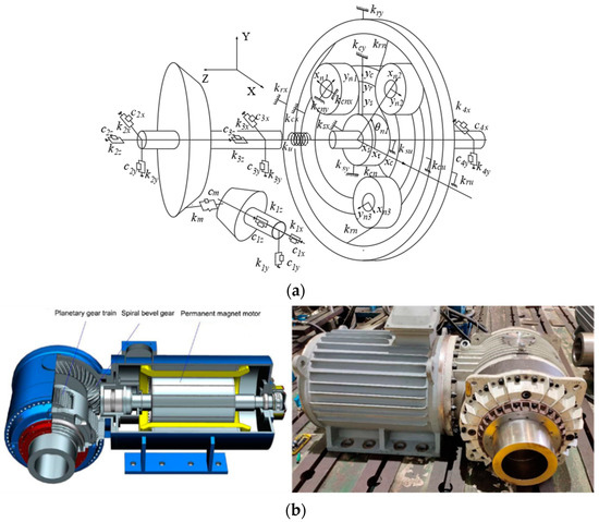
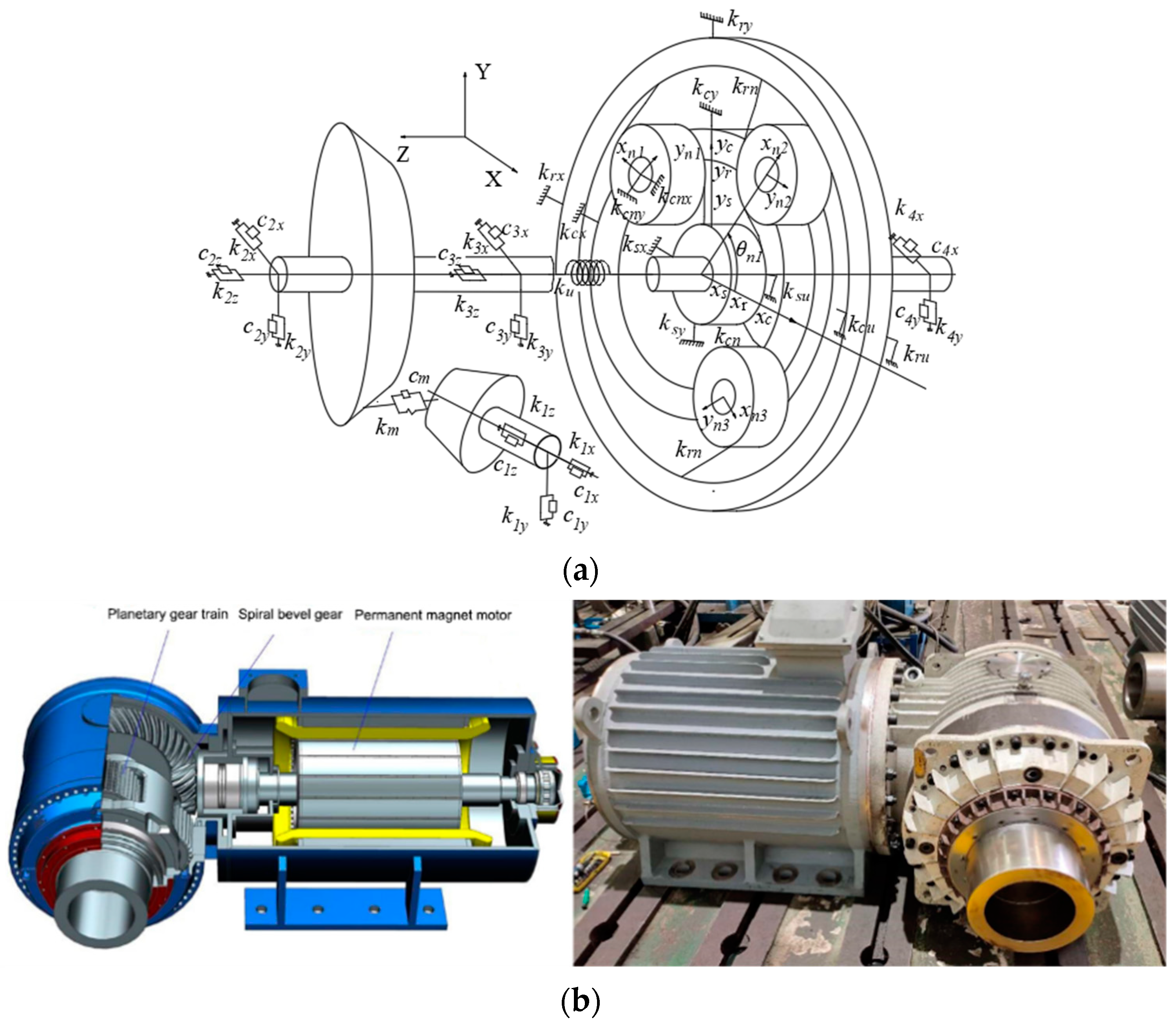
Figure 1a shows the dynamic model of a spiral bevel gear–planetary gear train. The whole system consists of a pair of bevel gears and a set of 2K-H planetary gears. Figure 1b shows the physical model of the transmission system.
Figure 1.
Dynamic model and physical model of the transmission system. (a) Dynamic model of the transmission system. (b) Physical model of the transmission system.
In the bevel–planetary gear transmission system, a coupling dynamic model containing bending–torsional–axial effects was established for the spiral bevel gears. Since all planet gears are spur gears, a bending–torsional coupling model is established for the planetary gear train. The axial force generated by the bevel gear is transmitted to the bearings through the shaft segment, then to the box, and finally to the frame through the fixed bolt. Therefore, the planetary gears are not subject to axial force.
2.1. Dynamic Equation of a Spiral Bevel Gear
The right-angle coordinate system was established by taking the intersection point of the two axes of the drive and driven gears as the coordinate origin. The axis of the drive bevel gear was the X axis, and the axis of the large bevel gear was the Z axis. Both the large and small bevel gears had four degrees of freedom (DOFs), these were two bending directions, the torsional direction of the rotation axes, and the axial direction.
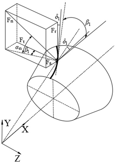
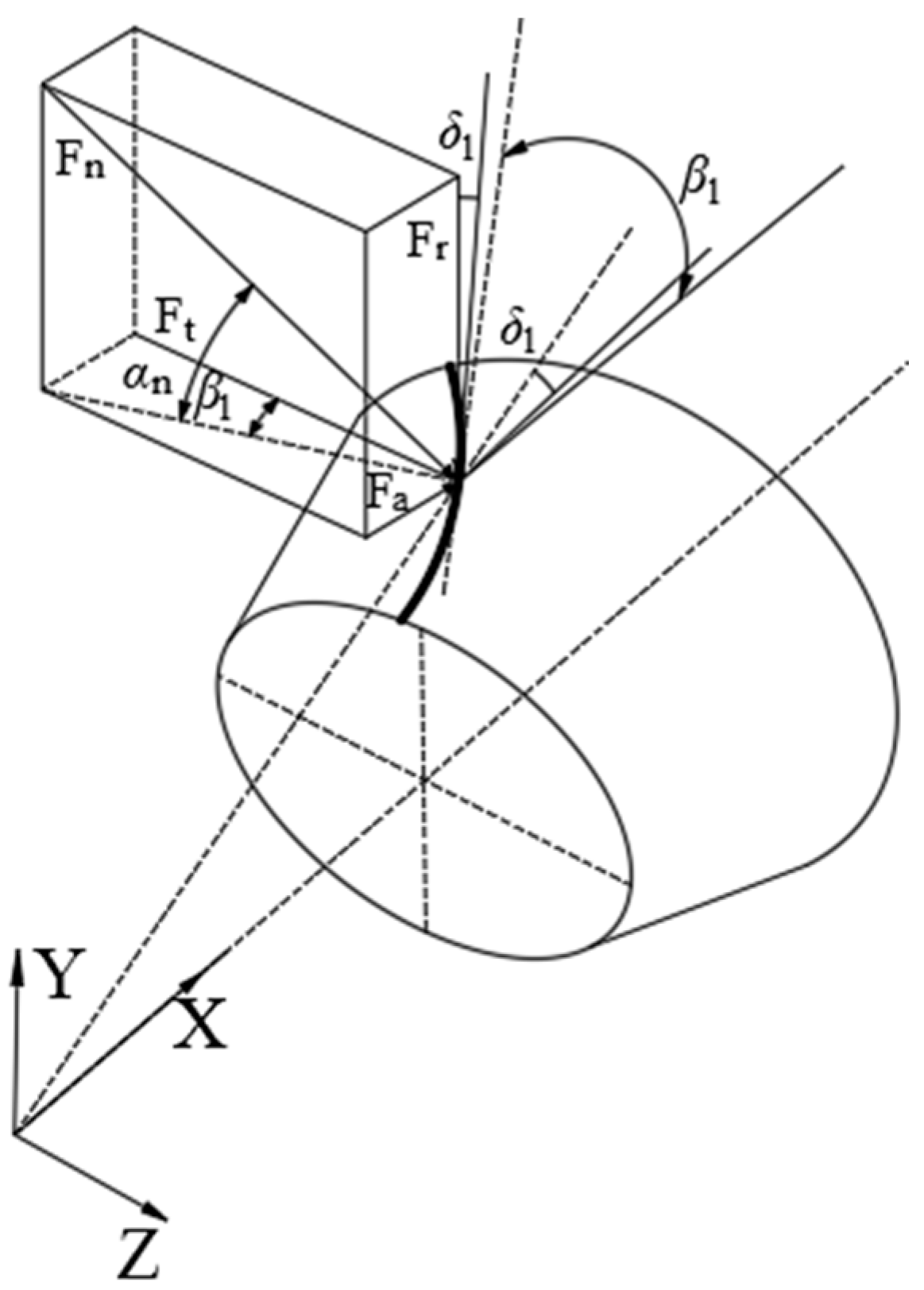
As shown in Figure 2, the normal dynamic load of the mesh gears and its component forces along each coordinate direction could be obtained according to the mechanical relations of the drive bevel gear.
Figure 2.
Force analysis of the drive bevel gear’s teeth.
Here, km(t) represents the time-varying mesh stiffness; cm is the mesh damping; αn is the normal pressure angle; β1 is the helix angle at the midpoint of the small bevel gear; δ1 represents the pitch cone angle of the small bevel gear.
We assumed that
The generalized displacement coordinates of the bevel gear pair can be expressed as follows:
where xi, yi, and zi (i = p, g) are the displacements of the drive gear (p) or the large gear (g) in three directions. θxp and θzg represent the torsion angles of the gears around the X axis and Z axis, respectively. By projecting the large and small bevel gear vibration displacements along the line of action, the relative displacement can be obtained as follows:
where em(t) represents the normal mesh error of the gear pair; rp and rg are the equivalent base radii at the gear reference points.
According to Newton’s second law, the dynamic differential equations for the spiral bevel gear pair can be expressed as follows:
where mp and mg are the large and small bevel gear masses, respectively; Ixp and Izg represent the rotational inertias of the gears around the X axis and Z axis; T1 is the input torque; T2 is the output torque; kij (i = 1, 2; j = x, y, z) represents the stiffness coefficient of each part in the direction of coordinate axis; cij (i = 1, 2; j = x, y, z) is the damping coefficient of each part in the direction of coordinate axis; ku means the torsional stiffness of the shaft segment. uij (i = x, z; j = p, g) represents the displacement of the gear in the torsional direction, and us is the torsional line displacement of the sun gear.
2.2. Dynamic Model of the Planetary Gear Transmission
As shown in Figure 1, the sun gear is represented by s, r is the ring gear, c is the planet carrier, and the planet gear is represented by n. OiXiYi is the dynamic coordinate system of each part. xi, yi, and θi (i = s, c, r, n1, n2, n3) indicate the translational and torsional elastic deformations of each part. kix and kiy (i = s, c, r, n1, n2, n3) represent the support stiffness of each bearing in the X and Y directions. kiu (i = s, c, r) is the torsional stiffness of each part. θni (i = 1, 2, 3) is the mounting angle of the planet gears.
For the subsequent calculations, the displacement of the gear mesh pair along the line of action is denoted by ui = ri × θi, where ri (i = s, c, r, n1, n2, n3) is the base radius of each gear, and ui (i = s, c, r, n1, n2, n3) represents the torsional line displacement of each part.
Projecting the mesh pair between the sun gear and the planetary gears along the direction of the line of action, the relative deformation is expressed by δsni (i = 1, 2, 3). The projected relative deformation of the ring–planet gear mesh pair along the line of action is represented by δrni (i = 1, 2, 3). The projected relative deformations between the planetary gear and the planet carrier along the xni and yni axes are δcnxi and δcnyi.
where θsni = α + θni(i = 1, 2, 3), θrni = α − θni(i = 1, 2, 3). θsni and θrni are the angles between the line of action of the sun and planetary gears and the X axis, as well as the angles between the line of action between the planetary wheel and internal ring gear and the X axis, respectively. θni is the installation angle of the ith planetary wheel. α is the pressure angle, and esn(t) and ern(t) are comprehensive mesh errors.
According to Newton’s second law, the dynamic differential equations for the planetary transmission system can be obtained as follows [30].
The dynamic model of the sun gear is represented by
The dynamic differential equations of the planetary gear are
The dynamic equations of the ring gear can be obtained as follows:
The dynamic differential equations of the planetary carrier are expressed as follows:
where mi (i = s, c, r, n) is the mass of the sun gear, planet, ring gear, and carrier. Ii (i = s, c, r, n) represents the moment of inertia of the sun gear, planet gear, ring gear, and planet carrier. kin (i = s, r) is the mesh stiffness between each mesh pair. kcn is the support stiffness between the carrier and planetary gear. ki (i = s, c, r) is the support stiffnesses of the sun, the ring gear, and the planet carrier. rc is the radial distance from the axis’ center of the planet to the geometric center of the planet carrier. Ti (i = p, g) represents the input and output torque of the planetary transmission system.
The general dynamic differential equation of the combined spiral bevel gear and planetary transmission system can be obtained by combining Equation (5) with Equation (13).
where M is the whole mass matrix of the system; C is the whole damping matrix; K is the whole stiffness matrix; F is the excitation vector; q is the generalized displacement vector of the system; e(t) represents the comprehensive mesh errors.
3. Dynamic Analysis of the System
3.1. Parameters of the Model
It is assumed that the planetary gears are uniformly distributed, and each planet has the same inertia, mass, mesh stiffness, and support stiffness. The support stiffnesses of the sun, the planet carrier, and the ring gear in the X and Y directions are the same. The drive system is applied to a bucket elevator and is the main drive part of the bucket elevator’s drive system. The bucket elevator is mainly used for vertical transportation of concrete, so it needs to maintain a low speed and high torque. The drive power of the bucket elevator is 90–280 kW, and the output speed is 16–30 r/min. According to the product design manual, the input power of the drive system is 200 kW, the input speed is 300 r/min, and the input torque is 6367 N·m [31]. The basic parameters of the gear transmission are shown in Table 1.
Table 1.
Basic parameters of the gear transmission.
The meshing frequency of each part of the system can be calculated according to the basic parameters. The first-order rotation frequency of the motor rotor is 50 Hz, which is the same as the power frequency. The first-order meshing frequency of the bevel gear meshing is 60 Hz, and the first-order meshing frequency of the planetary gear system meshing is 25 Hz. It can be found that the second- and third-order meshing frequencies of each component have a corresponding relationship of multiples with the first-order meshing frequency.
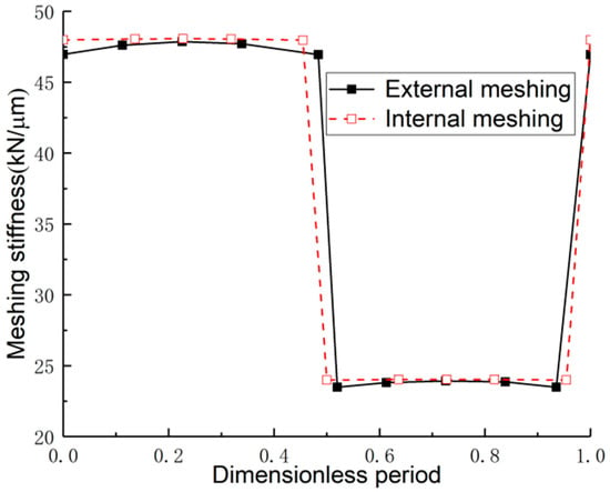
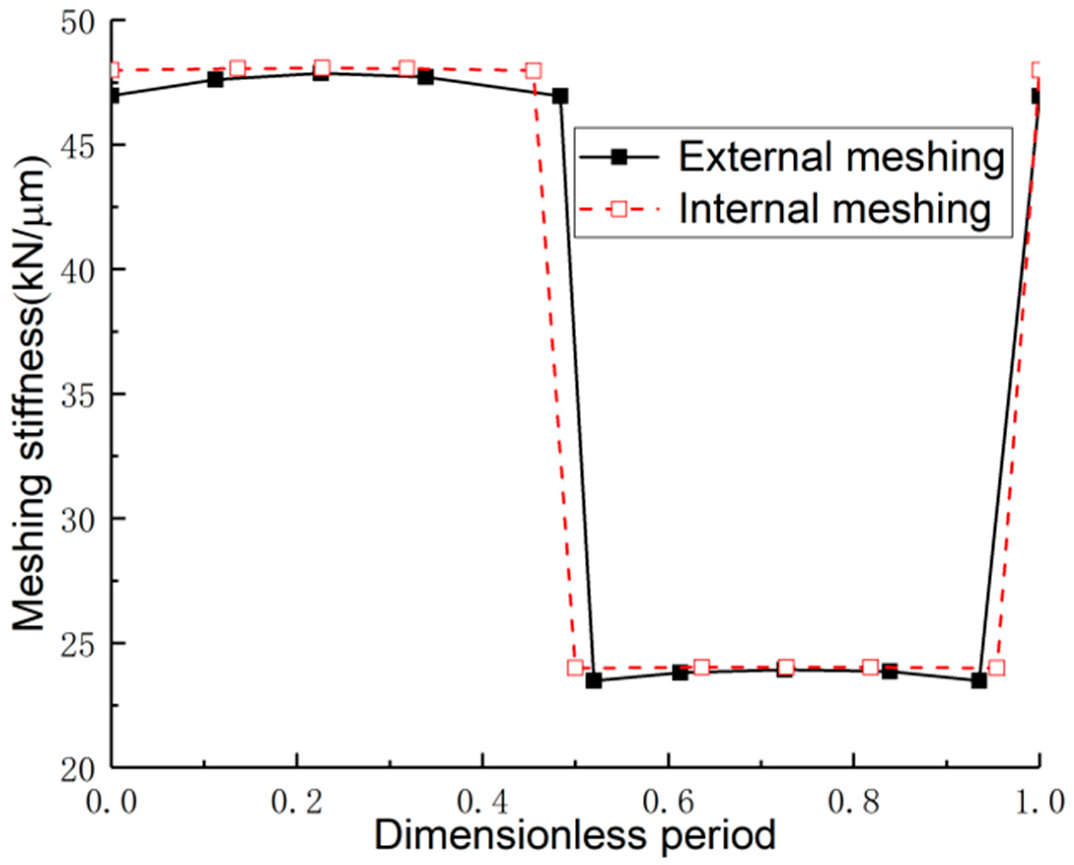
The mesh stiffness km(t) of the spiral bevel gear is calculated with the finite element method. Based on the idea of the energy slice method and according to [32], the time-varying meshing stiffness of a single pair of teeth is calculated when the coincidence ratio of the planetary transmission is 1. The time-varying mesh stiffness of the internal and external gear pairs can be given in Figure 3. The figure shows the change in meshing stiffness in a cycle. The dimensionless period is the ratio of the time that a pair of teeth pass from entering the meshing position to the meshing period. The number of gears participating in the meshing changes alternately with the rotation angle of the gear during meshing, so the meshing stiffness of the gear also changes periodically with time. When two pairs of gears are engaged in the transmission, the meshing stiffness can be regarded as the parallel connection of two pairs of teeth, that is, the superposition of the comprehensive stiffness of a single pair of teeth. The stiffness of double-tooth meshing is greater than that of single-tooth meshing. In the transition region of single- and double-tooth meshing, the gear meshing stiffness has a sudden change.
Figure 3.
Time-varying mesh stiffness.
3.2. Dynamic Transmission Error
The dynamic displacement of the system can be obtained by solving the dynamic model of the transmission system with Newmark’s integration method. Further, the dynamic transmission error of the gear pair along the direction of the line of action is calculated with Equation (15) [33]. We define the sun gear and planetary gear 1 as the external mesh pair 1, and we define the sun gear and planetary gear 2 as the external mesh pair 2. The rest of the mesh pairs can be defined in the same manner.
where V is the displacement transform vector; q is the displacement vector of the mesh unit.
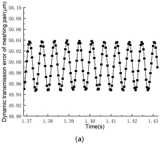
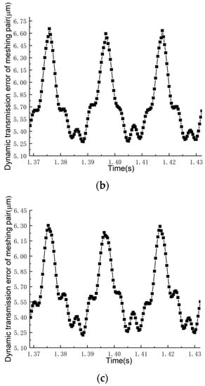
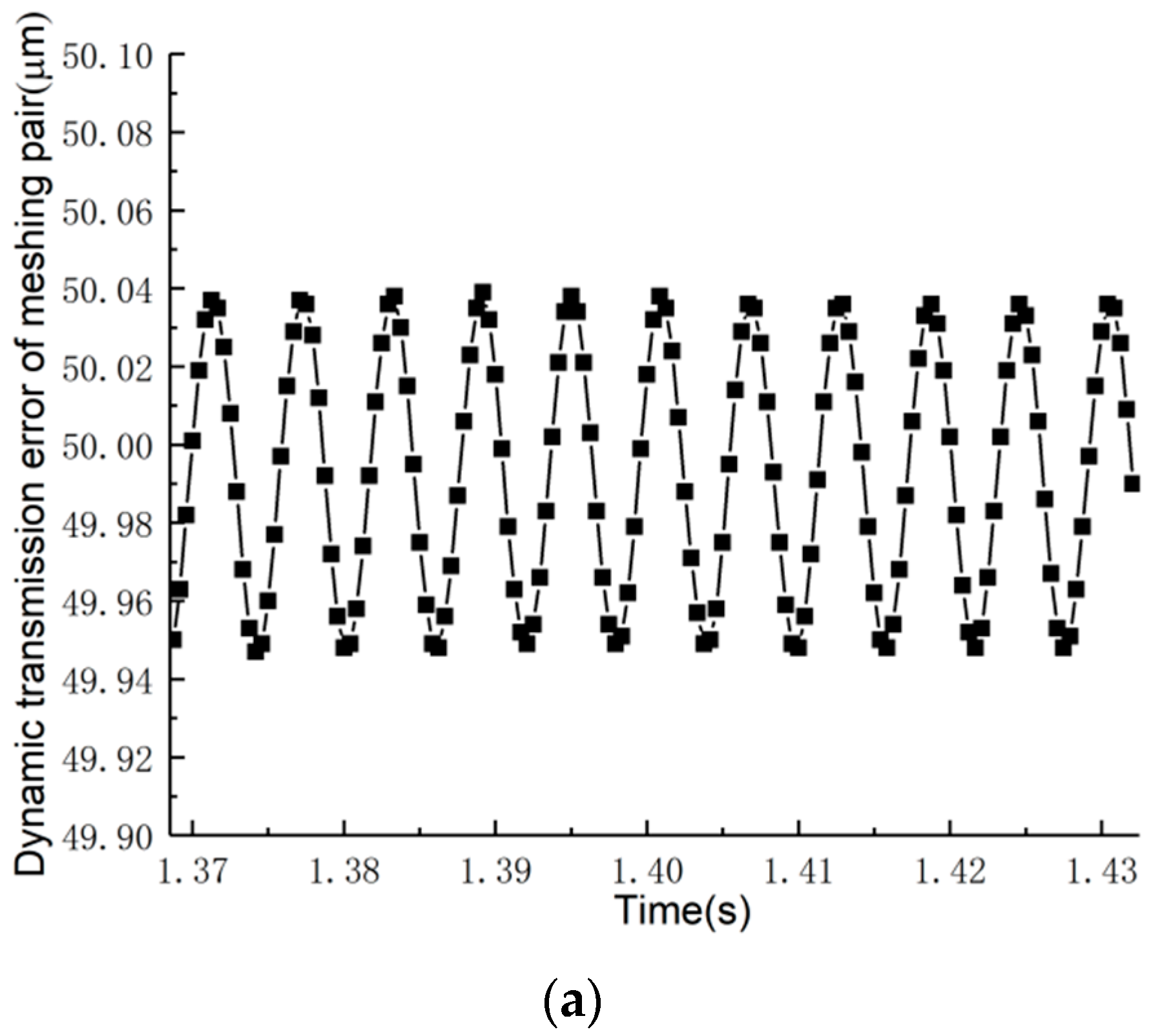
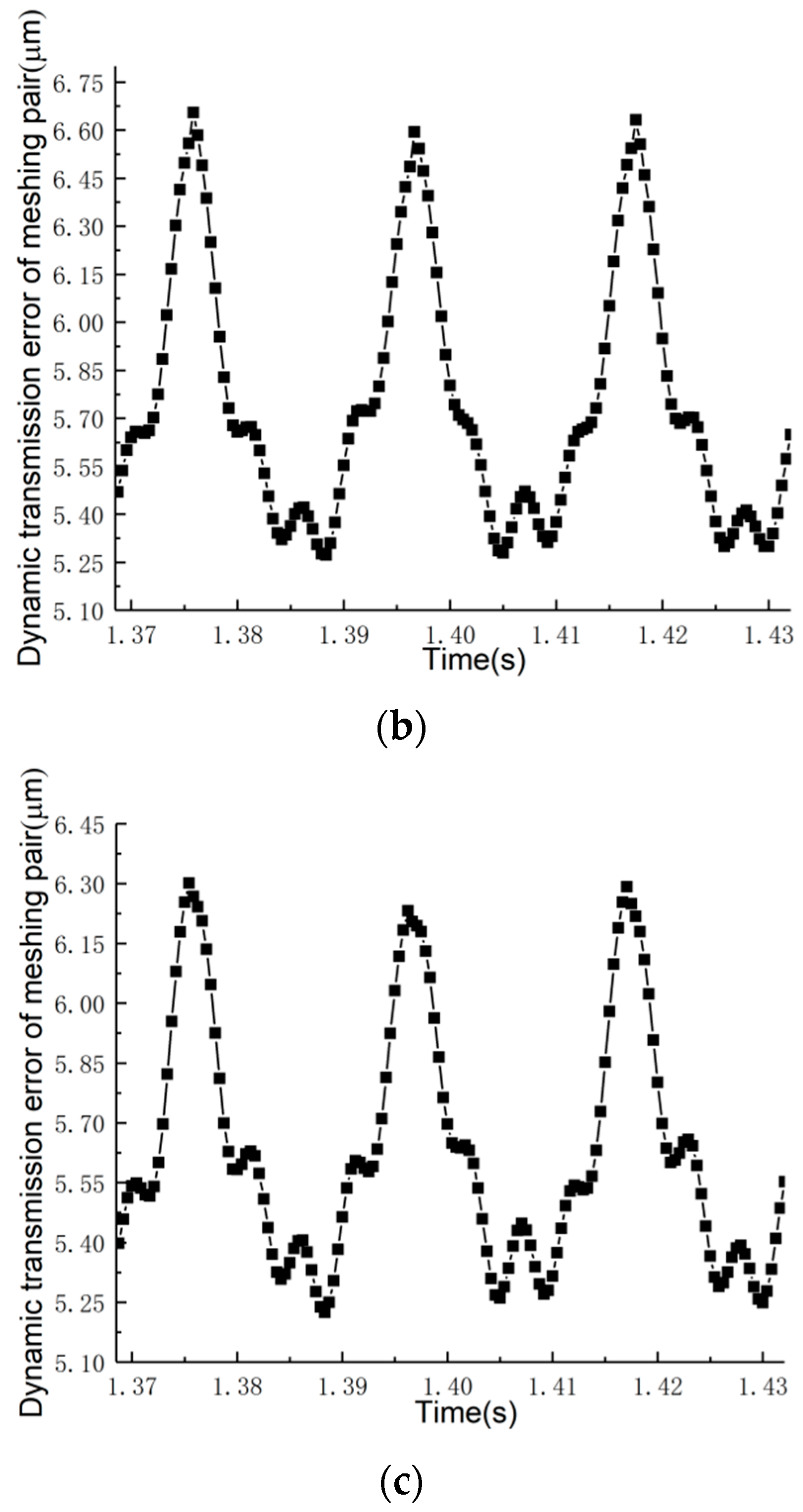
Figure 4 shows the dynamic transmission error of each gear pair. Here, three meshing cycles of the result after reaching a steady state are selected for the analysis. Because the speed of the bevel gear is higher than that of the planetary gear train, the dynamic transmission error of the bevel gear pair is obviously larger than that of the planetary gear train. For the planetary gear pair, the variation tendency of the dynamic transmission error is almost the same. By comparing the results with those in [34], it can be found that the peak value of the dynamic transmission error of each gear pair is within a reasonable range.
Figure 4.
Dynamic transmission error of the gear pairs. (a) The spiral bevel gear pair. (b) The mesh pair of the sun and the planet. (c) The mesh pair of the inner ring gear and the planet.
3.3. Dynamic Mesh Force
After obtaining the dynamic transmission error of a gear pair, the dynamic mesh force of the gear pair can be obtained with Equation (16).
where kij(t) (i = s, r; j = n) represents the mesh stiffness of the ith gear pair; δij(t) (i = s, r; j = n) represents the relative displacement between gear pairs.
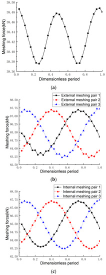
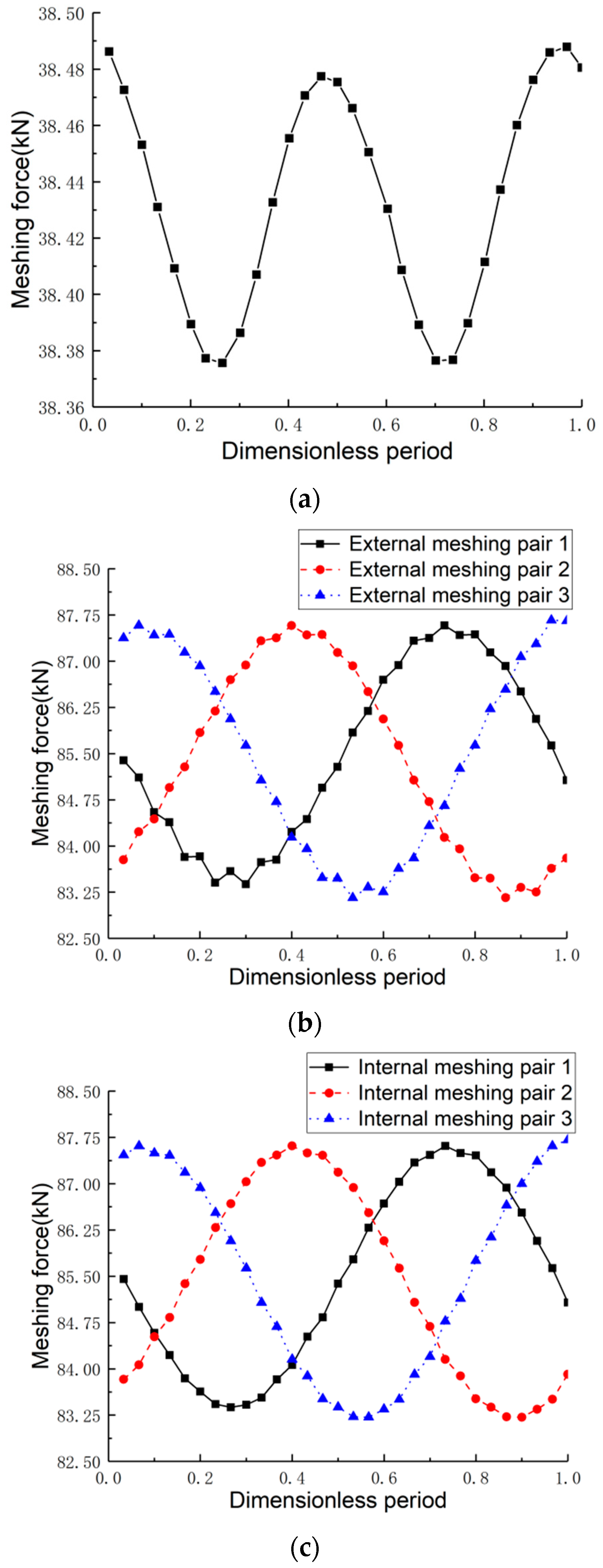
Figure 5 shows the dynamic mesh force of each gear pair. The maximum value of the dynamic mesh force between the bevel gear pairs is 3.85 × 10⁴ N. The average value of the mesh force is around 3.84 × 10⁴ N. Because the planets are mounted at different angles, this will lead to a phase difference in the results of the analysis. In Figure 5b, it can be observed that the maximum dynamic mesh force of the first external mesh gear pair is 8.76 × 10⁴ N, and the average mesh force is around 8.55 × 10⁴ N.
Figure 5.
Dynamic response of the mesh force. (a) Mesh force of the spiral bevel gear pair. (b) Mesh force between the sun and the planet. (c) Mesh force between the inner ring gear and the planet.
The maximum value of the dynamic mesh force of the second outer gear pair is 8.75 × 10⁴ N, and the average mesh force is around 8.53 × 10⁴ N. The maximum dynamic mesh force of the third external gear pair is 8.77 × 10⁴ N, and the average value is around 8.56 × 10⁴ N.
In Figure 5c, it can be observed that the maximum dynamic mesh force of the first internal gear pair is 8.76 × 10⁴ N, and the average mesh force is around 8.55 × 10⁴ N. The maximum dynamic mesh force of the second internal gear pair is 8.76 × 10⁴ N, and the average force is about 8.53 × 10⁴ N. In the transmission system, due to the different mesh phases of each planet, the mesh forces are slightly different in their peaks and fluctuation amplitudes. The peak value of the dynamic meshing force of gear pairs at all levels is less than the force calculated with the empirical formula, and the peak value of the dynamic meshing force is within a reasonable range [35].
3.4. Influence of Rotational Speed on Dynamic Mesh Force
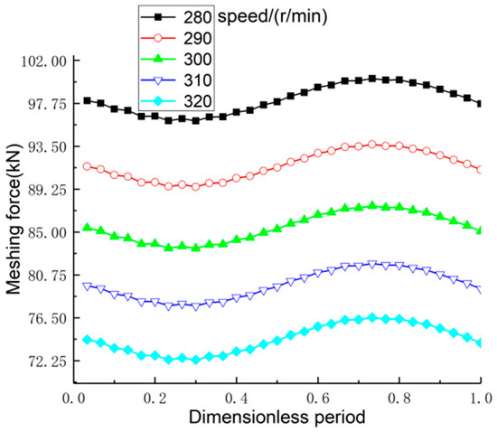
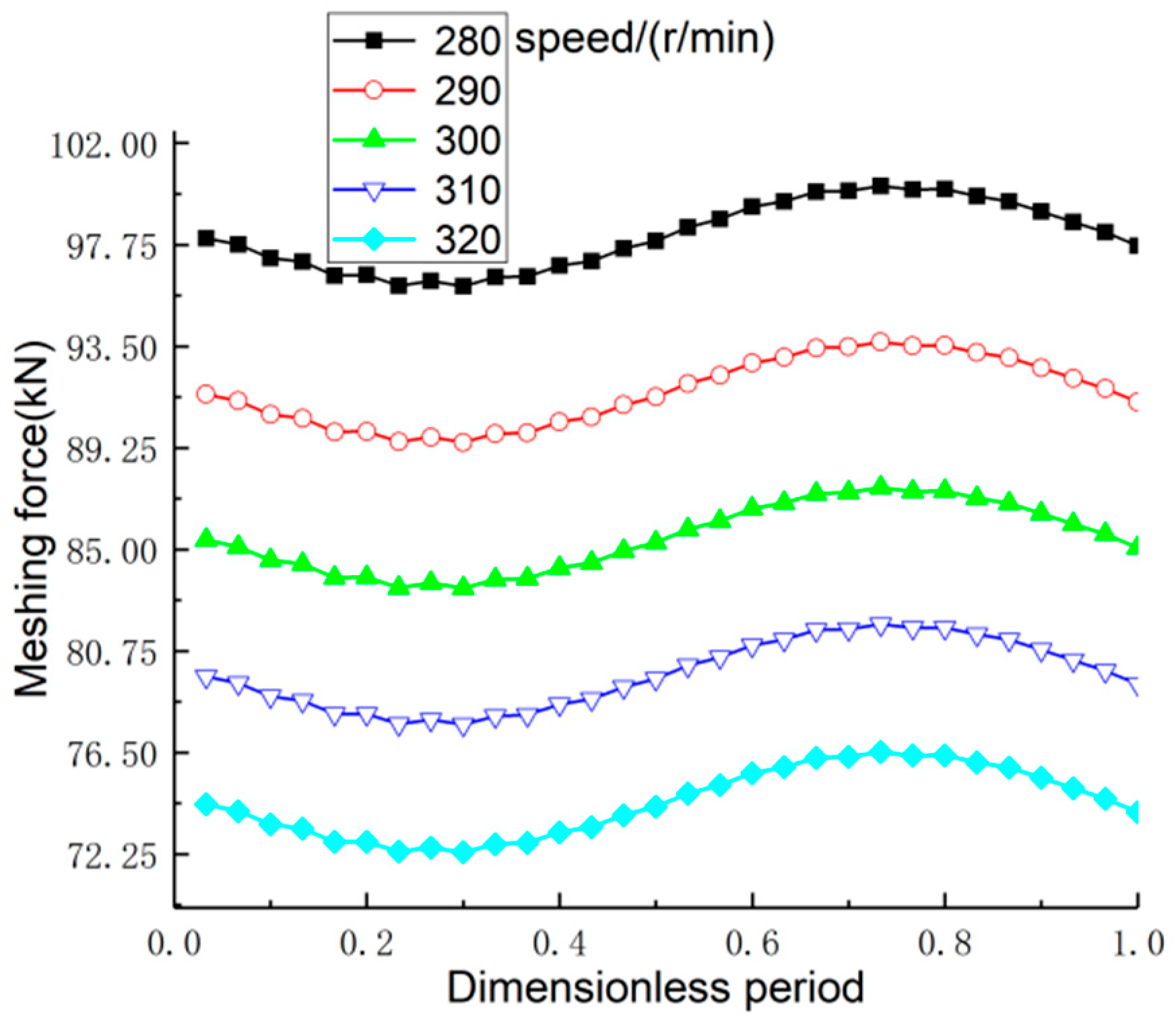
Figure 6 shows the influence of different rotational speeds on the first external mesh pair. The effects of rotating speed on the internal meshing pair force are similar. When the rotating speed reaches 280 r/min, the maximum external mesh force is equal to 100.22 kN; when the input speed is 320 r/min, the maximum external mesh force is equal to 76.53 kN. As mentioned above, the mesh force decreases as the rotating speed increases. When the power remains unchanged, the input speed increases, the input torque decreases, and the decrease in torque makes the mesh force decrease.
Figure 6.
Effects of different rotational speeds on the external mesh force.
3.5. Influence of Different Loads on Dynamic Mesh Force
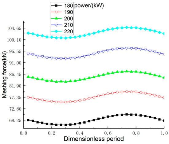
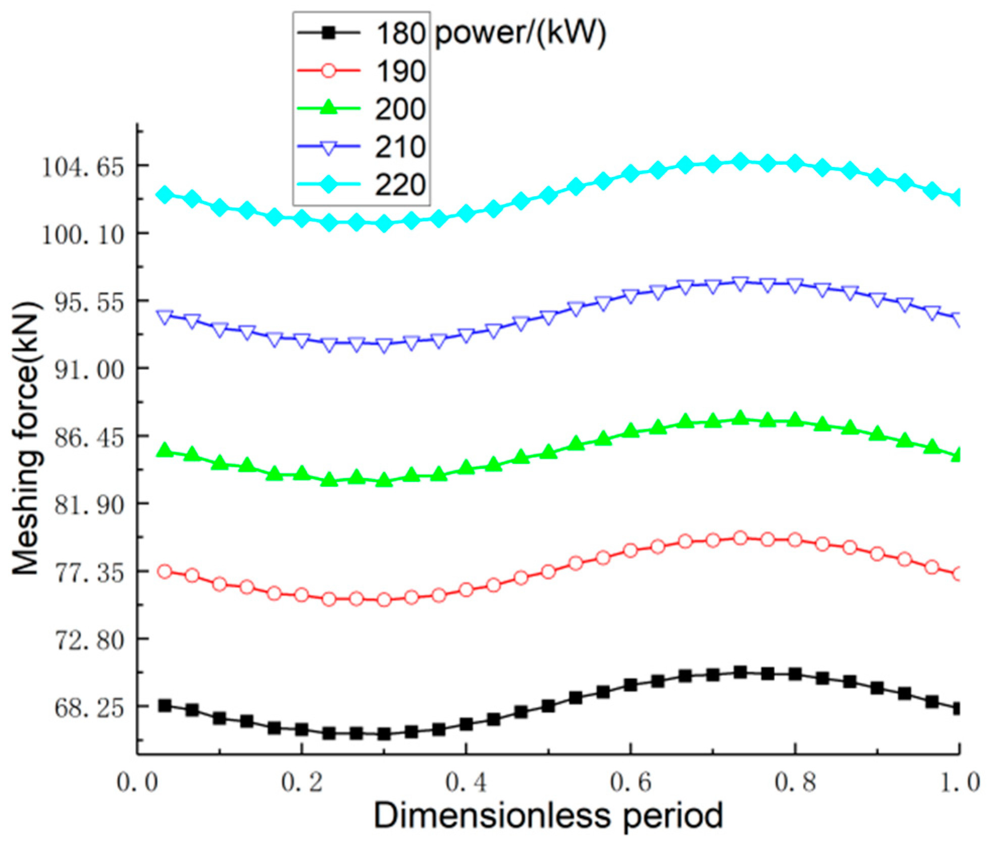
Figure 7 shows the influence of different power levels on the first external mesh gear pair. The effects of power on the internal meshing pair force are similar. When the input power reaches 180 kW, the maximum external mesh force is equal to 70.54 kN; when the input power is 220 kW, the maximum external engagement force is equal to 104.94 kN. As mentioned above, the mesh force increases as the power increases. When the speed is constant, the input power increases, the input torque increases, and the increases in the torque make the mesh force increase.
Figure 7.
Effects of different power values on the external mesh force.
4. Discussion and Validation
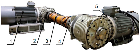
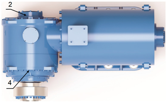
To verify the validity of the dynamic model of the spiral bevel gear–planetary gear transmission system, a vibration test device for a bucket elevator drive system was established. As shown in Figure 8, a coupling, adapter plate, and torque meter were used to connect a tractor motor with a bucket elevator drive system. The test equipment and the types used are shown in Table 2. The dynamic characteristics of the drive system were studied by adding measurement points to the box. As shown in Figure 9, set measuring point 2 and measuring point 4 were placed on the box to measure vibration. Measuring points 2 and 4 corresponded to bearings 2 and 4, respectively. In Figure 1a, k2 and c2 marked on the left side of the large bevel gear represent bearing 2, and k4 and c4 marked on the right side of the planetary gear train represent bearing 4.
Figure 8.
Test platform for the dynamic characteristics of a bucket elevator drive system. 1: tractor motor; 2: adapter plate; 3: coupling; 4: torque meter; 5: Drive system.
Table 2.
Test equipment.
Figure 9.
Sampling position of the measuring points.
When carrying out a no-load test on the drive system, the vibration speed data at the measuring point were collected every 5 min before reaching the rated speed, and the vibration speed data were collected every 15 min after reaching the rated speed. The data acquisition instrument was connected with the vibration measurement system and a monitor. Then, the speed without load is controlled by the speed sensor, and the vibration response of each measuring point was measured with a vibration probe. Finally, the vibration data were recorded with the data acquisition instrument.
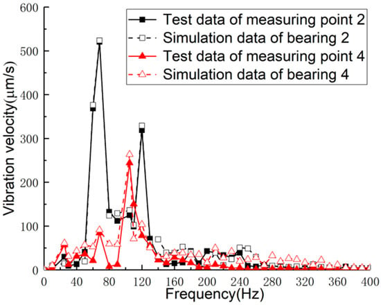
The vibration velocity of the bearing was obtained by solving the dynamic differential equations for the second bearing and the fourth bearing. The vibration velocity spectrum of the bearing could be obtained with a fast Fourier transform. Figure 10 indicates the variations in the vibration velocity of the measurement points in the frequency domain. Comparing the simulation results with the experimental results, it could be found that the overall change trend of the simulation data was more consistent with the trend of the measured data, with a slight difference at the peak. As shown in Table 3, the differences between the test and simulation data were 3.80% and 8.84%, which verified the validity of the simulation model. In conjunction with Section 2.1, the peak values at point 2 in the test and simulation data were mainly concentrated at 50, 60, and 120 Hz, which were the same as the first-order excitation frequency of the motor rotor and the first-order and second-order excitation frequencies of the bevel gear. Therefore, it can be considered that the vibration of the spiral bevel gear was mainly affected by the meshing frequency and the motor excitation. The peak values at point 4 in the test and simulation data were mainly concentrated at 50 and 100 Hz, which were the same as the first-order excitation frequency of the bevel gear and the second-order excitation frequency of the planetary gear. Therefore, it could be considered that the vibration of the planetary gear carrier was mainly caused by the first-order excitation frequency of the planetary gear set and the second-order excitation frequency of the spiral bevel gear.
Figure 10.
Vibration velocities in the tests and simulations.
Table 3.
Comparison of the vibration velocities between the tests and simulations.
The efficiency of the whole system was tested through the test platform that was built. After starting the tractor motor first, the system was operated at the rated power and rated voltage without load. When the bearing temperature and oil pool temperature became stable, the measurement and recording of the input power were implemented once. Then, to connect the drive system with the tractor motor, the system was run at the rated voltage and rated power without load. When the bearing and oil pool became stable, the input power was measured and recorded again, and the efficiency of the drive system was obtained. The test results show that the transmission efficiency of the whole system including the motor was 94.1%. The calculated value of the motor efficiency was 96.7%. The transmission system included the spiral bevel gear and the planetary gear train, and the total efficiency of the transmission system was 96.6%. Therefore, the calculated efficiency of the drive system including the motor reached 93.4%, which can be obtained with Equation (17). Due to friction and loss during transmission, the actual efficiency of the system was smaller than the calculated value, but the error value was also within the acceptable range. The transmission device of a traditional bucket elevator includes a hydraulic coupler and reducer. The reducer has two stages, and the transmission efficiency is 95%. The efficiency of the hydraulic coupler is 95%. The total efficiency of a traditional transmission system including the motor is only 87.3%. It could be found that the improved transmission system eliminated the hydraulic coupler, reduced the loss of efficiency, and introduced spiral bevel gears and planetary gear trains with higher transmission efficiency, so the transmission efficiency was significantly improved.
where η1 is the transmission efficiency of the spiral bevel gear; η2 is the transmission efficiency of the planetary gear train; η represents the total efficiency of the transmission system.
5. Conclusions
The dynamic model of a combined spiral bevel gear and planetary gear train set was developed based on the lumped mass method. The effects of time-varying gear mesh stiffness and errors of the mesh pairs were considered in this model. The dynamic transmission errors and dynamic mesh forces of each gear pair were obtained with Newmark’s integration method in the system.
The vibration of the spiral bevel gear in the transmission system was mainly caused by the motor excitation and the gear mesh frequency. The vibration of the inner ring of the planetary gear system was mainly caused by the first-order mesh frequency of the planetary gear and the second-order mesh frequency of the bevel gear. The influence of the input torque made the dynamic transmission error of the spiral bevel gear pair significantly larger than that of the planetary gear system. By analyzing the influences of different input rotation speeds and power on the dynamic mesh force, we found that the dynamic mesh force gradually decreased with the increase in speed, and it increased with the increase in power. For a low-speed heavy-load transmission system, the influence of power on the mesh force was more significant. It could be found that the efficiency of the transmission system was improved according to a comparison of test and simulation data. The validity of the dynamic model of the spiral bevel gear–planetary gear train was validated by comparing the vibration results at the same measurement points in the experiment and simulation. In future research, the dynamic characteristics of the drive system can be further studied, and a permanent magnet synchronous motor and drive system can be introduced to study an electromechanical coupling system.
Author Contributions
Conceptualization, Z.H.; methodology, Z.H., Z.X., and L.C.; validation, Z.H. and Z.X.; formal analysis, Z.H. and Z.X.; project administration, Z.H. and L.C.; investigation, Z.X; data curation, Z.X. and Q.Z.; writing—original draft preparation, Z.X.; writing—review and editing, Z.H., Q.Z. and L.C.; All authors have read and agreed to the published version of the manuscript.
Funding
This research was funded by [Shaanxi Natural Science Foundation of China] grant number [2021JM-166].
Institutional Review Board Statement
Not applicable.
Informed Consent Statement
Not applicable.
Data Availability Statement
Not applicable.
Conflicts of Interest
The authors declare no conflict of interest.
Nomenclature
| C | overall damping matrix |
| cm | mesh damping |
| cij | damping coefficient of the gear in the direction of the coordinate axes (N·s/m) |
| em(t) | normal mesh error of gear pair |
| esn(t) | comprehensive mesh errors between the sun and planet |
| ern(t) | comprehensive mesh errors between the ring and planet |
| F | excitation vector (kN) |
| Ixp | rotational inertia of gears around the X axis (kg·m2) |
| Izg | rotational inertia of gears around the Z axis (kg·m2) |
| Ii | moment of inertia of each part (kg·m2) |
| K | overall stiffness matrix |
| ku | torsional stiffness of the shaft segment (N·m/rad) |
| ki | support stiffnesses of the sun/ring and planet carrier (N/m) |
| kij | stiffness coefficient of the gear in the direction of the coordinate axis |
| kix | support stiffness of each bearing in the X directions (N/m) |
| kiy | support stiffness of each bearing in the Y directions (N/m) |
| kiu | torsional stiffness of each part (N·m/rad) |
| kin | mesh stiffness between each gear pair |
| kcn | support stiffness between the planet gear and carrier (N/m) |
| km(t) | time-varying mesh stiffness |
| kij(t) | mesh stiffness of the ith gear pair |
| M | overall mass matrix of the system (kg) |
| mp | mass of the small bevel gear (kg) |
| mg | mass of the large bevel gear (kg) |
| mi | mass of the sun/planet gear, ring, and planet carrier (kg) |
| q | generalized displacement vector of the transmission system |
| rp | equivalent base radius at the small bevel gear reference points (m) |
| rg | equivalent base radius at the driven bevel gear reference points (m) |
| ri | base radius of each gear (m) |
| rc | radial distance from the axis center of the planet to the geometric center of the planet carrier (m) |
| T1 | input torque (N·m) |
| T2 | output torque (N·m) |
| Tp | input torque of the planetary transmission system (N·m) |
| Tg | output torque of the planetary transmission system (N·m) |
| ui | torsional line displacement |
| V | displacement transform vector |
| xi | translational deformation in the X direction |
| yi | translational deformation in the Y direction |
| α | pressure angle (°) |
| αn | normal pressure angle (°) |
| β1 | helix angle at the midpoint of the small bevel gear (°) |
| δ1 | pitch cone angle of the small bevel gear (°) |
| δsni | relative deformation along the line of action for the mesh pair between the sun and the planet |
| δrni | projected relative deformation of the ring and planetary gear mesh pair along the line of action |
| δcnxi | projected relative deformations between the planetary gear and carrier along the xni axis |
| δcnyi | projected relative deformations between the planetary gear and carrier along the yni axis |
| θxp | torsion angles of gears around the X axis |
| θzg | torsion angles of gears around the Z axis |
| θi | torsional elastic deformation of each part in planetary gear train |
| θsni | angles between the line of action of the sun and planetary and X axis, |
| θrni | angles between the line of action of the planetary wheel and the internal ring gear and X axis |
| θni | installation angle of the ith planetary gear |
| η | transmission efficiency |
References
- Tang, D.G.; Chen, G.M. Current situation and prospect of gear transmission technology. J. Mech. Eng. 1993, 29, 35–42. [Google Scholar]
- Xu, J.L.; Zeng, F.C.; Su, X.G. Coupled bending-torsional nonlinear vibration and bifurcation characteristics of spiral bevel gear system. Shock Vib. 2017, 2017, 6835301. [Google Scholar] [CrossRef] [Scilit]
- Cheng, Y.P.; Lim, T.C. Dynamics of hypoid gear transmission with nonlinear time-varying mesh characteristics. J. Mech. Des. 2003, 125, 373–382. [Google Scholar] [CrossRef] [Scilit]
- Tang, J.-Y.; Hu, Z.-H.; Wu, L.-J.; Chen, S.-Y. Effect of static transmission error on dynamic responses of spiral bevel gears. J. Cent. South Univ. 2013, 20, 640–647. [Google Scholar] [CrossRef] [Scilit]
- Wang, L.; Huang, Y.; Li, R.; Lin, T. Study on nonlinear vibration characteristics of spiral bevel transmission system. China Mech. Eng. 2007, 18, 260–264. [Google Scholar]
- Wang, L.; Li, R.; Lin, T.; Huang, Y. Analysis for coupling vibration of a spiral bevel gear system. China Mech. Eng. 2006, 17, 1431–1434. [Google Scholar]
- Zeng, Z.; Ding, K.; He, G.; Li, W. Space-time model and spectrum mechanism on vibration signal for planetary gear drive. Mech. Syst. Signal Process. 2019, 129, 164–185. [Google Scholar] [CrossRef] [Scilit]
- Gou, X.-F.; Li, G.-Y.; Zhu, L.-Y. Dynamic characteristics of a straight bevel gear drive system considering multi-state meshing and time-varying parameters. Mech. Mach. Theory 2022, 171, 104779. [Google Scholar] [CrossRef] [Scilit]
- Dong, H.; Liu, Z.-Y.; Zhao, X.; Hu, Y.-H.; Liu, Y.Z.; Zhao, L.X.; Hu, H.Y. Analysis of dynamic characteristics of power split spiral bevel gear transmission system based on teeth geometric contact analysis. Trans. Can. Soc. Mech. Eng. 2019, 43, 47–62. [Google Scholar] [CrossRef] [Scilit]
- Xiang, L.; Deng, Z.Q.; Hu, A.J. Dynamical analysis of planetary gear transmission system under support stiffness effects. Int. J. Bifurc. Chaos 2020, 30, 2050080. [Google Scholar] [CrossRef] [Scilit]
- Yavuz, S.D.; Saribay, Z.B.; Cigeroglu, E. Nonlinear time-varying dynamic analysis of a spiral bevel geared system. Nonlinear Dyn. 2018, 92, 1901–1919. [Google Scholar] [CrossRef] [Scilit]
- Yavuz, S.D.; Saribay, Z.B.; Cigeroglu, E. Nonlinear dynamic analysis of a drivetrain composed of spur, helical and spiral bevel gears. Nonlinear Dyn. 2020, 100, 3145–3170. [Google Scholar] [CrossRef] [Scilit]
- Lafi, W.; Djemal, F.; Tounsi, D.; Akrout, A.; Walha, L.; Haddar, M. Dynamic modelling of differential bevel gear system in the presence of a defect. Mech. Mach. Theory 2019, 139, 81–108. [Google Scholar] [CrossRef] [Scilit]
- Lafi, W.; Djemal, F.; Tounsi, D.; Akrout, A.; Walha, L.; Haddar, M. Non-probabilistic interval process method for analyzing two-stage straight bevel gear system with uncertain time-varying parameters. Proc. Inst. Mech. Eng. Part C J. Mech. Eng. Sci. 2021, 235, 3162–3178. [Google Scholar] [CrossRef] [Scilit]
- Cao, W.; Pu, W.; Wang, J.X. Tribo-dynamic model and fatigue life analysis of spiral bevel gears. Eur. J. Mech. A Solids 2018, 74, 124–138. [Google Scholar] [CrossRef] [Scilit]
- He, Z.X.; Chang, L.H.; Liu, L. Dynamic response analysis of planetary gear transmission system coupled with gearbox vibrations. J. South China Univ. Technol. (Nat. Sci. Ed.) 2015, 43, 128–134+148. [Google Scholar]
- Gu, X.; Velex, P. A dynamic model to study the influence of planet position errors in planetary gears. J. Sound Vib. 2012, 331, 4554–4574. [Google Scholar] [CrossRef] [Scilit]
- Velex, P.; Chapron, M.; Fakhfakh, H.; Bruyère, J.; Becquerelle, S. On transmission errors and profile modifications minimising dynamic tooth loads in multi-mesh gears. J. Sound Vib. 2016, 379, 28–52. [Google Scholar] [CrossRef] [Scilit]
- Yang, H.; Li, X.; Xu, J.; Yang, Z.; Chen, R. Dynamic characteristics analysis of planetary gear system with internal and external excitation under turbulent wind load. Sci. Prog. 2021, 104, 368504211035604. [Google Scholar] [CrossRef] [Scilit]
- Jian, G.-X.; Wang, Y.-Q.; Zhang, P.; Li, Y.-K.; Luo, H. Analysis of lubrication performance for internal meshing gear pair considering vibration. J. Cent. South Univ. 2021, 28, 126–139. [Google Scholar] [CrossRef] [Scilit]
- Wang, C.X.; Dong, B.; Parker, R.G. Impact of planet mesh phasing on the vibration of three-dimensional planetary/epicyclic gears. Mech. Mach. Theory 2021, 164, 104422. [Google Scholar] [CrossRef] [Scilit]
- Wang, S.Y.; Zhu, R.P. Nonlinear torsional dynamics of star gearing transmission system of GTF gearbox. Shock Vib. 2020, 2020, 6206418. [Google Scholar] [CrossRef] [Scilit]
- Tang, X.; Bao, H.Y.; Lu, F.X. Nonlinear dynamic analysis of planetary gear train system with meshing beyond pitch point. Trans. Nanjing Univ. Aeronaut. Astronaut. 2020, 37, 884–897. [Google Scholar]
- Kahnamouei, J.T.; Yang, J.M. Development and verification of a computationally efficient stochastically linearized planetary gear train model with ring elasticity. Mech. Mach. Theory 2021, 155, 104061. [Google Scholar] [CrossRef] [Scilit]
- Wang, C.X.; Parker, R.G. Nonlinear dynamics of lumped-parameter planetary gears with general mesh phasing. J. Sound Vib. 2022, 523, 116682. [Google Scholar] [CrossRef] [Scilit]
- Yang, H.; Shi, W.; Guo, L.; Zhao, Y.; Yuan, R. Study on mesh stiffness and sensitivity analysis of planetary gear system considering the deformation effect of carrier and bearing. Eng. Fail. Anal. 2022, 135, 106146. [Google Scholar] [CrossRef] [Scilit]
- Xiang, L.; Gao, N.; Hu, A.J. Dynamic analysis of a planetary gear system with multiple nonlinear parameters. J. Comput. Appl. Math. 2018, 327, 325–340. [Google Scholar] [CrossRef] [Scilit]
- Wang, X. Nonlinear dynamic characteristics of fixed-axis gear wear in multistage gear transmission systems. Shock Vib. 2019, 2019, 5641617. [Google Scholar] [CrossRef] [Scilit]
- Karray, M.; Feki, N.; Khabou, M.T.; Chaari, F.; Haddar, M. Modal analysis of gearbox transmission system in bucket wheel excavator. J. Theor. Appl. Mech. 2017, 55, 253–264. [Google Scholar] [CrossRef] [Scilit]
- Wang, L.; Li, R.; Lin, T.; Yang, C. Analysis for coupled vibration of helical gear transmission system. Mach. Des. Res. 2002, 18, 30–31. [Google Scholar]
- Nanjing Gaojing Gear Group Co. Ltd. MGDS-E Series Bucket Lift Permanent Magnet-Gear Drive System; Nanjing Gaojing Gear Group Co. Ltd.: Nanjing, China, 2020. [Google Scholar]
- Chang, L.H.; He, Z.; Liu, L.; Liu, Q. Express method for determining the transmission error and mesh stiffness of helical gears. J. Vib. Shock. 2017, 36, 157–162+174. [Google Scholar]
- Chang, L.H. A Generalized Dynamic Model for Parallel Shaft Gear Transmissions and the Influences of Dynamic Excitations; Northwestern Polytechnical University: Xi’an, China, 2014. [Google Scholar]
- Liu, G. Low Noise Design Theory and Method of Gear Transmission; Science Press: Beijing, China, 2021. [Google Scholar]
- Pu, L.G.; Chen, G.D.; Wu, L.Y. Mechanical Design, 9th ed.; Higher Education Press: Beijing, China, 2013. [Google Scholar]

Disclaimer/Publisher’s Note: The statements, opinions and data contained in all publications are solely those of the individual author(s) and contributor(s) and not of MDPI and/or the editor(s). MDPI and/or the editor(s) disclaim responsibility for any injury to people or property resulting from any ideas, methods, instructions or products referred to in the content. |
© 2023 by the authors. Licensee MDPI, Basel, Switzerland. This article is an open access article distributed under the terms and conditions of the Creative Commons Attribution (CC BY) license (https://creativecommons.org/licenses/by/4.0/).