


Abstract
This study employed an integrated experimental–computational methodology to investigate the critical role of the layer-stacking sequence in the acoustic performance of multi-layer porous materials for vehicle NVH applications. The acoustic properties of four distinct single-layer materials were first characterized via impedance tube measurements. A finite element simulation model based on the Johnson–Champoux–Allard (JCA) theory was subsequently developed in COMSOL Multiphysics 6.2 and rigorously validated. Leveraging this validated model, a systematic analysis was conducted on six different layer sequences under a fixed total thickness of 30 mm. The simulation results showed excellent agreement with experimental data, with a root-mean-square error (RMSE) below 5%. It was demonstrated that the stacking sequence significantly governed the mid-to-high frequency sound absorption behavior, which was strongly correlated with the modulation of the real and imaginary parts of the normalized surface acoustic impedance. This study thus demonstrated that the layer sequence—a previously underexplored design factor—critically determines the absorption performance of multi-layer materials at a fixed total thickness. A full design-space analysis revealed that performance shifts are governed by changes in interfacial acoustic impedance. This physics-driven insight provides a practical framework for tailoring absorbers to specific frequency bands, offering a viable path toward lightweight acoustic solutions for electric vehicle applications.
1. Introduction
Driven by the ongoing transition toward vehicle electrification and intelligentization, electric vehicles (EVs) are fundamentally reshaping the landscape of personal mobility. This evolution, however, introduces a distinct set of challenges and opportunities in the domain of NVH. The absence of dominant internal combustion engine (ICE) noise in EVs unmasks previously secondary noise sources. Under high-speed operating conditions, high-frequency noises—such as electromagnetic whine from the traction motor and gear-meshing noise from the transmission system—become more perceptible. Although their overall sound pressure level may be moderate, their pronounced frequency content contributes to high psychoacoustic annoyance [1]. Failure to adequately attenuate these high-frequency components can significantly degrade in-cabin acoustic comfort and overall perceived quality. Prolonged exposure is known to contribute to auditory fatigue and may induce psychological stress during extended journeys [1]. In the context of automotive NVH analysis, noise is often categorized by frequency: low-frequency noise (typically below 500 Hz), associated with structural vibration and road booming; mid-frequency noise (roughly 500–2000 Hz), often linked to powertrain and tire–pavement interaction; and high-frequency noise (above 2000 Hz), dominated by components such as wind rush, gear whine, and electromagnetic noise. Therefore, a systematic approach to NVH refinement, aimed at developing a quiet and comfortable cabin acoustic environment, is paramount for enhancing the core competitiveness of EVs and delivering a superior user experience.
On the other hand, the industry’s demand for increased driving range in EVs imposes strict requirements for vehicle lightweighting. Conventional sound insulation materials, such as asphalt damping sheets and heavy sound-absorbing felts, often come at the cost of added weight, making it difficult to meet the dual demands of efficiency and environmental sustainability in the new era. In this context, the development of novel composite materials that combine high acoustic performance with lightweight characteristics has become a research focus in the NVH field. Among these, natural fiber composites show great potential for applications in components such as door panels and instrument boards due to their lightweight, biodegradability, and favorable specific stiffness and damping properties [2]. To address the challenges of mid-to-low frequency noise control in thin-walled structures such as doors and wheel housings in vehicles, studies proposed a multi-layer composite acoustic metamaterial using variable-section cavities and porous foam [3,4] as well as a perforated panel–fiberglass coupled system [5]; these approaches enhanced the broadband noise control effectiveness in the mid-to-low frequency range while maintaining the lightweight characteristics of the thin-walled construction.
The stringent spatial and weight constraints in modern vehicle design have made multi-layer porous composites (e.g., combining fibers and foams) a pivotal solution for achieving broadband sound absorption. While this approach is now mainstream, its development has been primarily driven by the dual—and often competing—imperatives of enhancing NVH performance and reducing mass.
A critical, yet under-characterized, design variable within this fixed-thickness paradigm is the sequencing of layers. Existing studies frequently suffer from three limitations that obscure a fundamental understanding: they either (1) test predetermined sequences without exploring the full combinatorial space, (2) fail to rigorously isolate thickness as an independent constraint, or (3) draw conclusions from an insufficient number of sequence comparisons [3,6,7,8,9,10,11,12]. Consequently, general, physics-based principles for layer sequencing remain elusive, leaving design processes reliant on suboptimal trial-and-error.
To bridge this gap, our study sets out to (1) establish and validate a robust experimental–computational framework grounded in the Johnson–Champoux–Allard (JCA) model; (2) execute a full-factorial investigation of all possible layer sequences within a three-material system at a fixed total thickness (30 mm); and (3) elucidate the governing physical mechanisms by correlating performance metrics with normalized surface acoustic impedance.
The principal contribution of this work is a systematically mapped design space coupled with causally explanatory insights. By linking absorption performance directly to impedance outcomes for every possible sequence, we transcend isolated case studies. Our analysis yields generalizable guidelines for tailoring multi-layer absorbers, offering a principled design methodology that replaces empirical guesswork with physics-informed strategy.
The study is structured in the following manner: Section 2 presents the theoretical foundation, detailing the JCA model and transfer matrix approach for sound absorption coefficient calculation; Section 3 describes the experimental materials, measurement methods, and simulation approaches; Section 4 provides results and discussion, systematically analyzing simulation and experimental outcomes while exploring underlying mechanisms and evaluates the practical effectiveness in automotive NVH applications; Section 5 summarizes the research conclusions and suggested directions for future work.
2. Theory
2.1. Porous Material Modeling and JCA Theory
Porous materials, such as the metallic fibers selected for this study, dissipate acoustic energy primarily through visco-thermal effects within their pores. Their acoustic performance is classically described by characteristic impedance and complex wavenumber, which are governed by microstructural parameters including flow resistivity, porosity, tortuosity, and characteristic lengths [13,14,15].
To predict these properties for design, we employed the Johnson–Champoux–Allard (JCA) model. This equivalent-fluid model characterizes a porous medium using five macroscopic parameters: porosity, flow resistivity, tortuosity, viscous characteristic length, and thermal characteristic length [16,17]. Its reliability in simulating the acoustic behavior of composite structures has been well established in automotive NVH applications, making it a foundational tool for linking material microstructure to macroscopic performance [18].
In this study, the JCA model serves a dual purpose: first, to accurately characterize the three selected porous metallic fiber materials, and second, to provide the theoretical basis for simulating the acoustic response of multi-layer sequences composed of these materials. This approach allows us to systematically isolate the effect of layer sequencing—our primary variable—within a fixed total thickness constraint.
The JCA model, established by Johnson, Champoux, and Allard [19,20,21,22], is adopted as the theoretical foundation. This model calculated the characteristic acoustic impedance and wavenumber through the computation of complex effective density and complex sound velocity. It comprehensively accounted for both viscous effects and thermal exchange interactions with the interconnected solid phase, thereby providing a complete description of sound wave propagation mechanisms in porous materials.
where
- ρ(ω)—equivalent density;
- K(ω)—dynamic bulk modulus;
- c(ω)—complex sound velocity;
- —characteristic acoustic impedance;
- —complex wavenumber;
- —tortuosity;
- —fluid density;
- —porosity;
- —flow resistivity;
- j—imaginary unit ;
- μ—dynamic viscosity;
- —viscous characteristic of length;
- γ—specific heat ratio;
- —absolute pressure;
- —thermal characteristic length;
- —Prandtl number.
2.2. Sound Absorption Coefficient
For a hybrid configuration with multiple material layers, the total transfer matrix [7] is calculated as the product of the individual layer transfer matrices in the order of wave propagation:
The transfer matrix for each layer of acoustic material is formulated as follows:
where
h—the thickness of each layer, i = 1, 2, 3 … n.
The surface impedance Zs, the reflection coefficient R and the normal sound absorption coefficient α of the multi-layer acoustic material can be calculated using
where
—the air characteristic impedance.
3. Materials and Methods
3.1. Integrated Experimental-Computational Framework
To systematically explore the layer-sequence design space under fixed thickness, we developed an integrated experimental–computational framework. This approach overcomes the key limitations of purely experimental or simulation-based methods when applied to multi-layer absorber optimization.
- Purely experimental optimization of all sequence permutations is often impractical due to the prohibitive cost and time required for fabricating and testing numerous samples.
- Conversely, purely simulation-based optimization relies on idealized material models, and its predictions require rigorous experimental validation to ensure physical accuracy.
Our hybrid framework synergizes both approaches through a three-step workflow:
- Parameter Calibration: We first characterized each constituent porous material using impedance tube measurements to inversely identify the five macroscopic parameters of the Johnson–Champoux–Allard (JCA) model, ensuring a physically accurate material representation.
- Model Validation: The calibrated JCA model was then implemented in a finite element simulation and rigorously validated against independent experimental data—from both single-layer and multi-layer configurations—as detailed in Section 3.4.3.
- Systematic Exploration and Analysis: The validated model served as a virtual testing platform to exhaustively evaluate all six possible layer sequences. Beyond predicting absorption coefficients, it provided direct access to physical fields such as normalized surface impedance, enabling a mechanistic analysis of performance differences.
This integrated methodology thus combines the physical fidelity of experimentation with the efficiency and analytical depth of simulation, establishing a reliable basis for the subsequent full-factorial design investigation.
3.2. Acoustic Materials
Four commercially available porous materials were selected to construct a representative library covering a broad spectrum of acoustic properties relevant to automotive packages. The selection was designed to span two key dimensions: material morphology (fibrous vs. foam) and flow resistivity (low to high).
The materials include the following:
- A1 and A2: Polyester fiber felts of different densities, representing low-to-medium flow resistivity fibrous absorbers commonly used in interior trim.
- Yellow Foam: A high-flow-resistivity rigid polyurethane foam, typical of dense materials used in dash insulators or underhood applications.
- PU18: A low-flow-resistivity flexible open-cell foam, analogous to lightweight acoustic foams used for high-frequency damping in pillars or headliners.
This combination provides a wide range of characteristic impedance and dissipation mechanisms (flow resistivity range: ≈104–105 N·s/m4; porosity: 0.95–0.99), enabling a systematic investigation of layer-sequence effects across acoustically contrasting material pairs. While specific performance values are material-dependent, the sequencing principles derived from these contrasts—such as impedance grading and front-layer dominance—are anticipated to be generalizable to other porous materials within comparable property ranges.
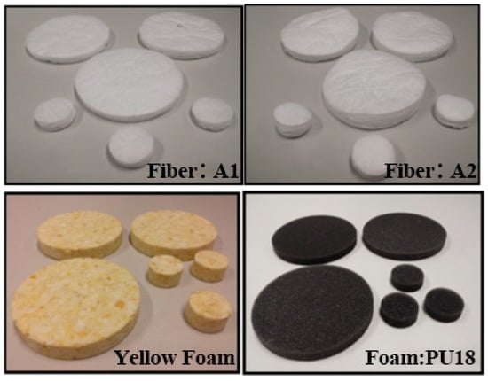
Materials A1 and A2 comprised two types of polyester fiber cotton with densities of 14.56 kg/m3 and 16.67 kg/m3, respectively. Materials designated as Yellow Foam and PU18 represented foam materials of different density grades, with densities of 179.03 kg/m3 and 20.989 kg/m3, correspondingly in Figure 1.
Figure 1.
Photographs of the four test samples.
Disk-shaped specimens of each material were fabricated with diameters of 30 mm and 100 mm to accommodate impedance tubes of corresponding diameters for installation and testing. The tested thicknesses of each material were specified as follows: A1—10.30 mm, A2—15.00 mm, Yellow Foam—16.08 mm, and PU18—10.14 mm. All acoustic measurements were conducted over a frequency range spanning from 200 Hz to 6300 Hz, covering both low-frequency and high-frequency intervals relevant to automotive NVH applications.
3.3. Measurement
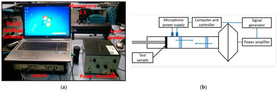
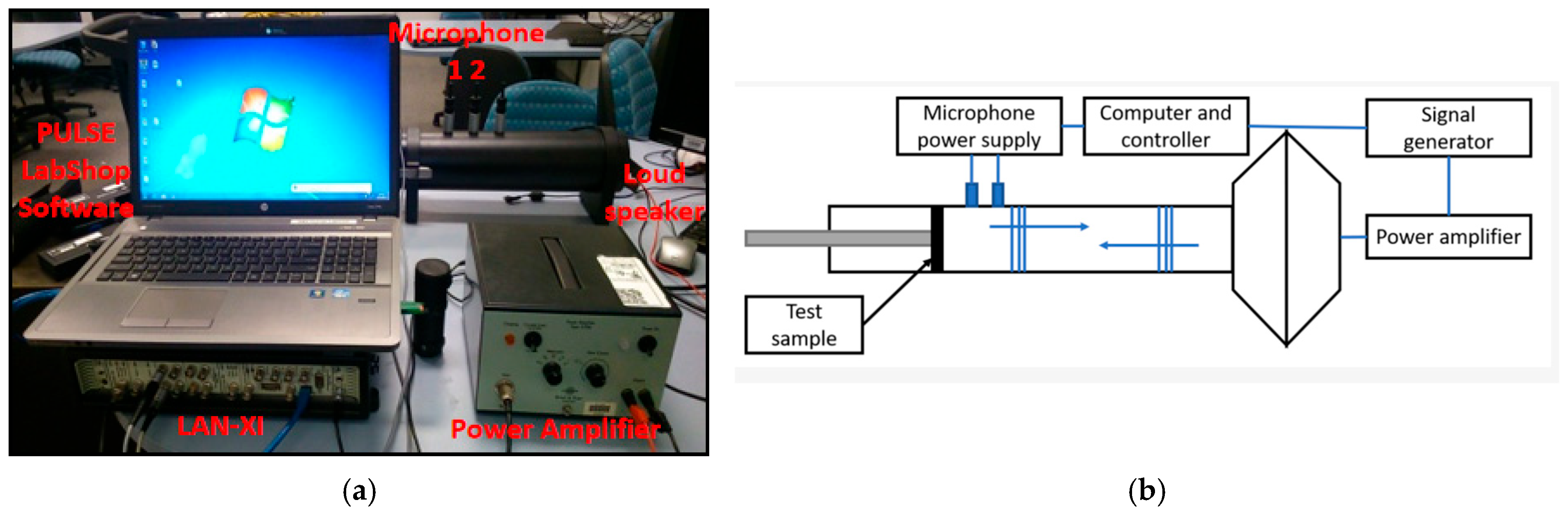
The testing equipment comprises the impedance tube (B&K 4206), two microphones affixed to the tube, and computer-based analysis software (Pulse LabShop 12), designed for quantifying the normal-incidence sound absorption characteristics of automotive interior components/test samples across a specified frequency range, as illustrated in Figure 2. This experiment adhered to the ASTM E1050-24 standard [23], employing the transfer function approach utilizing two microphones, and was conducted under environmental conditions of 22.3 °C, 51% relative humidity, with a sound velocity of 343.9 m/s and air density of 1.197 kg/m3. For this project, impedance tubes of varying diameters (30 mm and 100 mm) were utilized, with test samples matching their respective diameters placed inside for sound absorption coefficient measurements encompassing the frequency band between 200 and 6300 Hz. Sound absorption coefficients in the frequency range of 50–6300 Hz were measured using a standard two-microphone impedance tube setup. A large-diameter tube (100 mm) was employed for the low-to-mid frequency range (50–1600 Hz), and a small-diameter tube (30 mm) was used for the high-frequency range (1600–6300 Hz), in accordance with the ASTM E1050 standard.
Figure 2.
(a) Photograph of the impedance tube setup (B&K 4206). (b) Schematic diagram of the two-microphone impedance tube from Ref. [24].
To ensure accurate sound absorption coefficient measurements, the specimens were securely mounted at the tube’s end, facing the loudspeaker emitting a plane sound wave. The core physical process involved sound wave propagation within the impedance tube, followed by reflection at the sample–test interface. The resulting standing wave pattern was quantitatively characterized by analyzing the pressure differential captured between the two microphones. This established measurement mechanism formed the basis for subsequent acoustic parameter extraction. The reflection coefficient R and normal-incidence sound absorption coefficient α are formulated according to the Chung & Blaser Transfer Function Method [25,26]:
where H21 represents the modified transfer function, k denotes the wavenumber, l stands for the distance from the test sample to its nearest microphone, and s signifies the distance between two microphones. The sound absorption coefficient curves of the samples were plotted and analyzed using the Pulse LabShop software.
3.4. Numerical Simulation
3.4.1. Finite Element Simulation Model of the Impedance Tube
A 3D finite element modeling framework was established in COMSOL Multiphysics based on a 1:1 scale impedance tube experimental setup. For the large impedance tube (100 mm diameter, 520 mm length), the microphone was positioned 50 mm from the sample surface with an 80 mm microphone spacing, covering the 50–1600 Hz frequency range. The small impedance tube (30 mm diameter, 380 mm length) was configured with a 15 mm sample-to-microphone distance and 25 mm microphone spacing, operating in the 1600–6300 Hz range to comprehensively simulate acoustic characteristics across different frequency bands. Porous absorbers were placed at the tube end with a rigid backing.
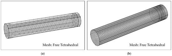
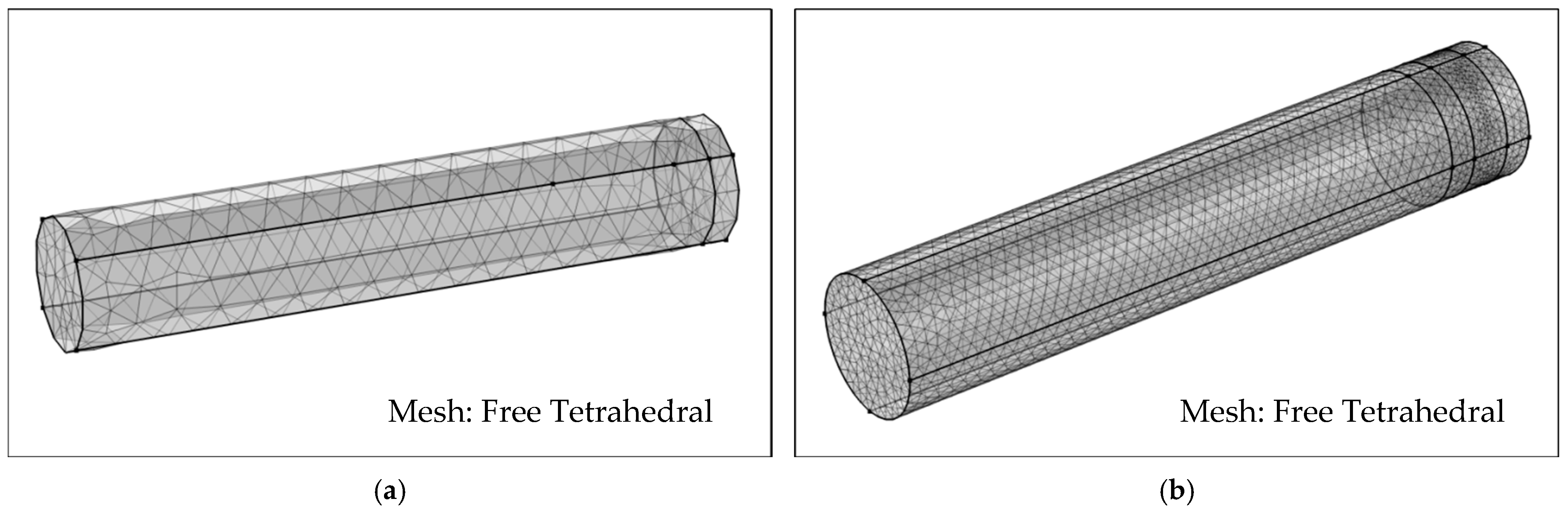
The JCA model was applied to characterize the porous materials, with properties defined according to measured acoustic parameters. The model was meshed with free tetrahedral elements for accuracy. A plane wave excitation (1 Pa) was applied at the inlet, and a no-slip condition was set along the tube walls. Integration surfaces were defined at microphone locations to extract sound pressures.
Utilizing the transfer function technique, the acoustic absorption coefficient was computed with the aid of user-defined variables within the COMSOL environment. Figure 3a shows the large-tube model; the small-tube setup was identical except in dimensions. In Figure 3b, a three-layer material assembly [27]—sample 2 (20 mm), sample 3 (30 mm), and sample 1 (20 mm)—was modeled in sequence from the source side, using the JCA model and a rigid backing to predict multi-layer absorption performance.
Figure 3.
Acoustic FEA model (meshed with free tetrahedral elements): (a) model for single-layer material testing; (b) model for a three-layer assembly.
A mesh convergence analysis was performed to ensure the independence of numerical results from spatial discretization. The global maximum element size was iteratively reduced, and the simulation was deemed converged when further refinement altered the computed normal-incidence sound absorption coefficient by less than 1% at all monitored frequencies.
This criterion was satisfied with a computationally efficient mesh, owing to the well-conditioned acoustic problem (plane wave propagation in a tube) and the use of higher-order elements. Converged models required approximately 2000–4000 tetrahedral elements for single-layer configurations and 90,000 elements for multi-layer assemblies.
The excellent agreement between subsequent simulation results and experimental data (RMSE < 5%) confirms both the spatial convergence and the overall fidelity of the modeling approach adopted in this study.
3.4.2. JCA Model Parameters
Founded on the JCA model, this research established the foundation for subsequent finite element analysis of acoustic materials. The methodology required the preliminary extraction of five essential physical parameters: flow resistivity, porosity, tortuosity, viscous characteristic length, and thermal characteristic length. These parameters constituted the fundamental inputs for performing accurate numerical simulations of sound-absorbing materials. The airflow resistivity (σ) was measured directly using an ASTM C522-compliant test bench (Brüel & Kjær, Nærum, Denmark) [28]. The remaining four JCA parameters—porosity (Φ), tortuosity (α∞), viscous characteristic length (Λ), and thermal characteristic length (Λ′)—were inversely identified through an optimization procedure [29,30,31,32,33], as their direct measurement is prohibitively complex and costly.
This inverse identification was framed as a constrained non-linear least-squares optimization problem. The objective was to find the parameter vector p = [Φ, α∞, Λ, Λ′] that minimizes the discrepancy between the measured and JCA-predicted normal-incidence sound absorption coefficients across 200–6300 Hz. The objective function was the sum of squared errors (SSE):
where αexp(fi) is the measured absorption coefficient, αJCA(fi,p) is the coefficient predicted by the JCA model combined with the transfer matrix method, and N is the number of frequency points.
To ensure physical plausibility, the parameters were constrained within typical microstructural ranges for fibrous and foam materials: Φ ∈ [0.90, 0.99], α∞ ∈ [1.0, 10.0], Λ ∈ [50, 500] μm, Λ′ ∈ [100, 1000] μm. The optimization was solved using a trust-region-reflective least-squares algorithm. To verify solution uniqueness and robustness, the procedure was repeated for each material with multiple random initial guesses within these bounds. All runs converged to a consistent parameter set, with the standard deviation of the final objective function value below 0.5%, confirming a stable and unique solution given the quality of the experimental data and the imposed physical constraints. The resulting inversely identified JCA parameters are summarized in Table 1.
Table 1.
The JCA parameters of the fibrous and foam materials.
3.4.3. Model Validation
This section implemented a two-stage validation methodology with the objective of verifying the established acoustic simulation model, beginning with a fundamental model validation where simulation results for single-layer materials were compared against impedance tube experimental data. Second, the model’s reliability in predicting the behavior of complex composite structures was assessed by replicating multi-layer configurations reported in the literature. All comparisons are quantitatively evaluated using the full-frequency-band RMSE.
- Validation of Single-Layer Materials: Examination of Fundamental Model Accuracy
The validity of the model primarily depended on its accurate characterization of the constitutive relationships of individual materials. Four representative porous sound-absorbing materials (A1, A2, Yellow Foam, and PU18) were selected and processed into specimens with four different thicknesses: 10.30 mm, 15.00 mm, 16.08 mm, and 10.14 mm. The normal-incidence sound absorption coefficient (α_exp), characterized through a B&K 4206 impedance tube following ASTM E1050-24 guidelines, established the experimental benchmark for all subsequent numerical model validation procedures.
The five JCA parameters for each material were obtained through an inverse parameter identification method and subsequently incorporated into the simulation model to calculate the theoretical α_sim under identical thickness conditions. Test results and simulation outputs were compared graphically to evaluate the consistency between the simulated values and the measured data in terms of the trends of major absorption peaks and valleys. To further eliminate subjective interpretation, the RMSE across the 200–6300 Hz frequency range was calculated for each specimen to quantify the prediction accuracy of the model.
- Model Validation and Analysis of Multi-layer Coupling Effects
Following the successful validation of the single-layer material model, this study further evaluated the model’s capability to handle interfacial coupling effects in multi-layer structures. A three-layer porous composite structure reported in the literature [27] was accurately replicated as a validation case. The model strictly adopted the material parameters and layer thicknesses provided in Table 2 of the cited literature without any parameter adjustments, ensuring the objectivity of the validation process. A validation study comparing the predicted acoustic performance with the experimentally obtained literature data demonstrated that the model accurately characterized the inter-layer acoustic coupling effects. This validation established a reliable foundation for subsequent prediction of the noise control performance of engineered multi-layer assemblies.
Table 2.
Acoustic characteristic parameters of porous materials (data taken from Ref. [27]).
3.4.4. Acoustic Performance Investigation of Multi-Layer Configurations
Following the completion of model validation, this study systematically investigated the correlation between ply sequence and acoustic attenuation. Three materials with distinct acoustic characteristics were selected: A2 (medium-flow-resistivity fibrous material), Yellow Foam (ultra-high-flow-resistivity dense-pore foam), and PU18 (low-flow-resistivity open-cell foam), with their key parameters summarized in Table 1.
To ensure comparative fairness, the total thickness of all multi-layer configurations was fixed at 30 mm, comprising three equal-thickness sub-layers (10 mm each). Through systematic permutation, six different three-layer configurations were obtained (Table 3). Each configuration was defined according to the wave propagation path, specifically describing the layer sequence from the incident surface to the rigid backing.
Table 3.
Configuration of the designed multi-layer acoustic material.
4. Results and Discussion
4.1. Model Validation: From Single to Multi-Layer Structures
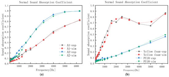
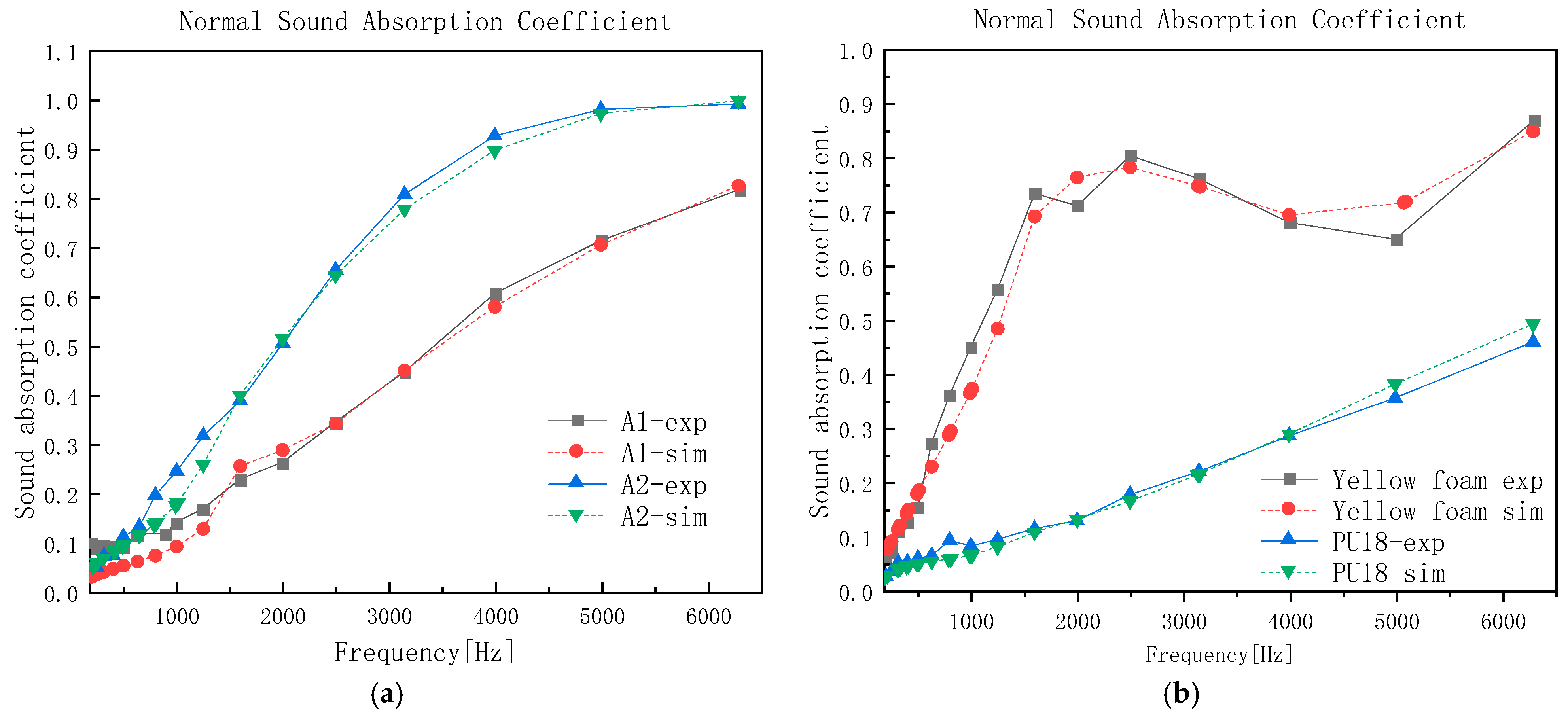
The simulation results for single-layer materials were first validated experimentally. As illustrated in Figure 4, the simulated curves for the four single-layer materials with different thicknesses—A1 (10.30 mm), A2 (15.00 mm), Yellow Foam (16.08 mm), and PU18 (10.14 mm)—demonstrated excellent agreement with impedance tube measurements over the complete frequency domain.
Figure 4.
Validation of the simulation model for single-layer materials: comparison between experimental data and simulation results (a) A1 and A2, and (b) Yellow Foam and PU18.
Quantitative analysis presented in Table 4 shows that all four comparisons achieved RMSE values below 5%. Among these, PU18 with a thickness of 10.14 mm exhibited the best agreement, with an RMSE of only 1.39%. These results confirmed that the inversely identified JCA parameters effectively characterized the material’s acoustic response, and that the established simulation framework provided high accuracy in predicting single-layer performance, thereby laying a reliable foundation for subsequent multi-layer structure simulations.
Table 4.
RMSE analysis of sound absorption predictions for single-layer materials.
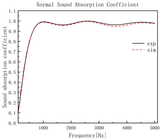
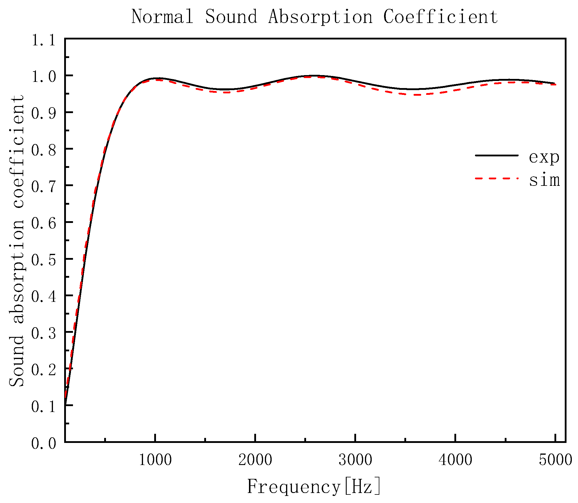
To further validate the model’s capability in handling multi-layer composite structures, a classical multi-layer case from Reference [27] was reproduced. The finite element model was configured using material properties and geometric dimensions directly obtained from referenced literature. Simulation results demonstrated exceptional consistency with experimental measurements, showing precise agreement in both resonance characteristics and broadband absorption behavior. Quantitative evaluation revealed outstanding predictive accuracy across the 50–5000 Hz frequency spectrum, achieving a RMSE of merely 2.13%. The comprehensive comparative analysis between simulated and experimental data was graphically presented in Figure 5. This minimal deviation confirms the model’s accuracy in predicting the acoustic performance of multi-layer structures.
Figure 5.
Validation of the multi-layer simulation model: comparison between experimental data and simulation results (adapted from Ref. [27]).
The validation results convincingly demonstrated that the established model was applicable not only to single-layer materials but also effectively addressed sound wave propagation in multi-layer composite structures, accurately predicting inter-layer interactions and their impact on overall acoustic performance. This capability ensured its reliability and practical value in the design and optimization of novel engineered multi-layer absorbers.
Detailed analysis of Figure 4 and Figure 5 indicated limited acoustic efficacy of single-layer materials. This performance limitation was particularly evident in both the mid-to-low frequency spectrum and the constrained functional bandwidth. In contrast, structures composed of multiple stacked single-layer materials achieved significant wide-band acoustic attenuation. This comparison underscored the advantage of multi-layer designs in expanding the absorption bandwidth and enhancing low-to-mid frequency performance, thereby providing clear direction for subsequent research on layer sequence optimization.
4.2. The Influence of Layer Sequence on Noise Control
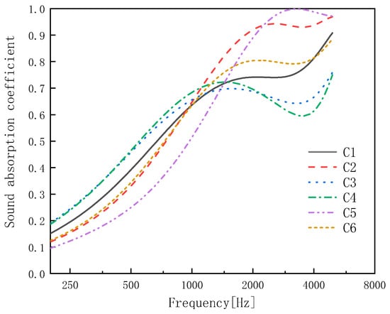
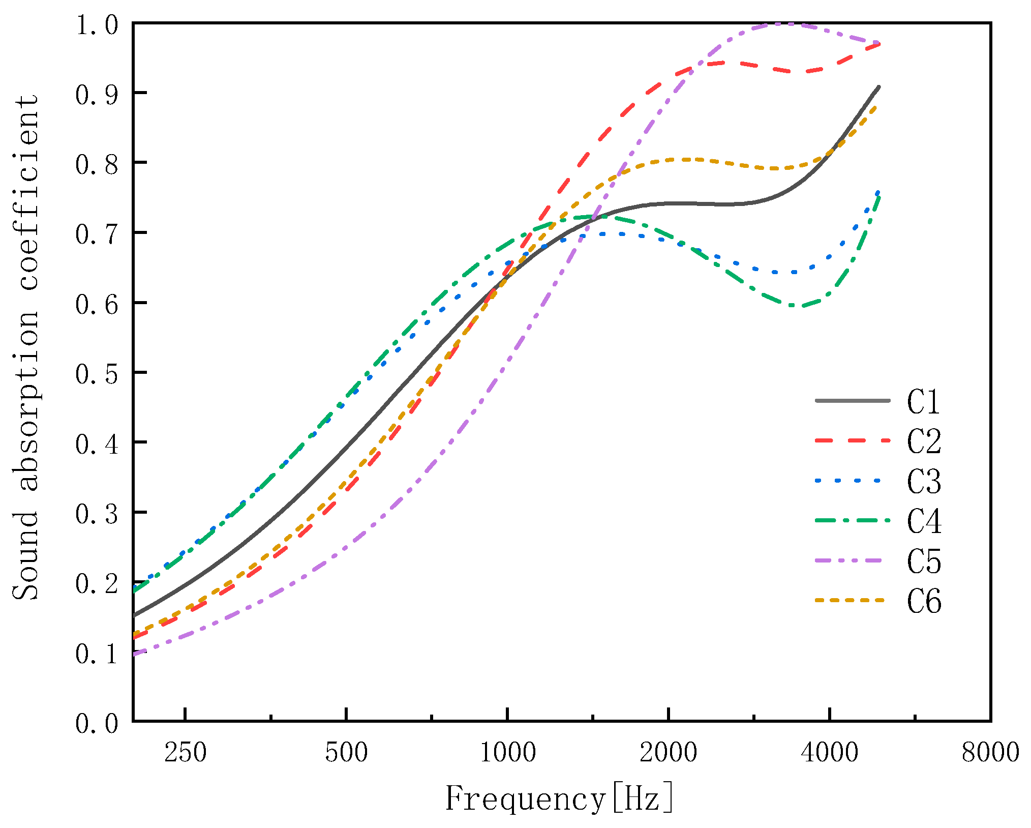
This study characterized six distinct layer-sequencing arrangements (C1–C6) under fixed 30 mm total thickness conditions. Performance assessments spanned the 200–5000 Hz frequency domain, with particular emphasis on fundamental acoustic indicators: the sound absorption coefficient and the complex components of normalized acoustic impedance.
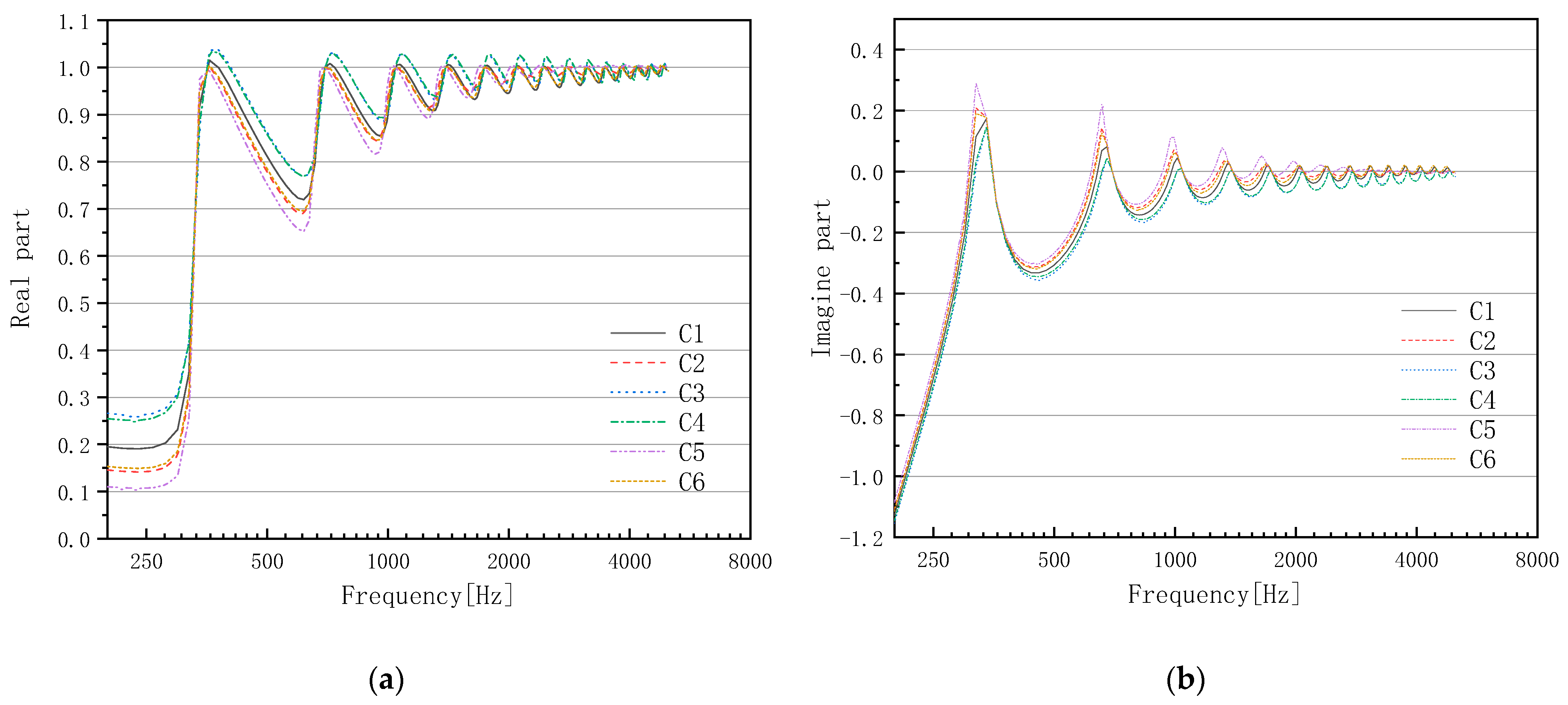
As shown in Figure 6 and Figure 7, among the three layer-sequence configurations (C1, C2, and C3), the C1 structure exhibited the optimal sound absorption performance across most frequency bands (particularly above 1000 Hz), with a peak absorption coefficient exceeding 0.74. Configuration C3 also demonstrated favorable performance in the mid-frequency range, whereas C2 showed generally weaker absorption capability.
Figure 6.
Sound absorption coefficients for all six layer-sequence configurations (C1–C6).
Figure 7.
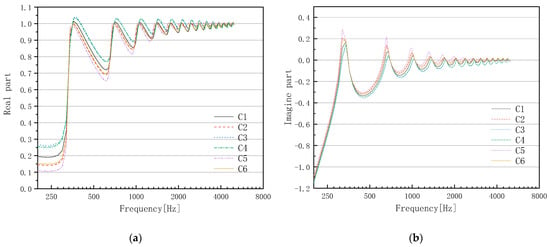
Normalized surface acoustic impedance for all six configurations: (a) real part; (b) imaginary part.
The real part of the acoustic impedance reflects the sound energy loss ability, while the imagine art characterizes the reactive behavior and resonance properties. Analysis revealed that the normalized real parts of C1, C2, and C3 predominantly ranged between 0.9 and 1.05, indicating effective energy dissipation in all three configurations. Their imaginary parts displayed multiple zero-crossings with significant oscillations, suggesting pronounced resonance phenomena. Notably, the C1 configuration exhibited the most gradual variation in the imaginary part, confirming its superior broadband sound absorption characteristics.
As shown in Figure 6 and Figure 7, among the three layer-sequence configurations (C4, C5, and C6), the C5 structure demonstrated the most outstanding performance in the high-frequency range (>2500 Hz), with a maximum sound absorption coefficient exceeding 0.99. Configuration C4 exhibited a distinct broadband absorption peak in the mid-frequency region (1000–2000 Hz), reaching approximately 0.72. Configuration C6 displayed relatively balanced broadband absorption characteristics, showing particularly good performance in the 2000–3000 Hz range.
The normalized real parts of all three configurations were concentrated within the 0.8–1.05 range, indicating effective sound energy conversion in each case. Their imaginary parts exhibited significant fluctuations in the 300–400 Hz band, revealing noticeable low-frequency resonance absorption mechanisms. Among them, C5 showed the most gradual variation in the imaginary part, suggesting that its absorption mechanism was predominantly governed by viscous dissipation, while C6 demonstrated typical broadband acoustic response characteristics.
These performance differences indicated that the layer sequence significantly influenced the sound energy dissipation mechanisms and frequency response characteristics by altering the acoustic impedance matching properties and internal wave reflection behavior.
The systematic performance variation across configurations C1–C6 is rooted in the fundamental physics of wave propagation in layered media. Crucially, the transfer matrix for the entire stack (Equation (6)) is the non-commutative product of the individual layer matrices, meaning that T1·T2 ≠ T2·T1. Therefore, altering the layer sequence intrinsically changes the total system response (surface impedance and absorption).
While analytical optimization of sequence might be possible for simplified two-layer cases with explicit impedance expressions, it becomes intractable for arbitrary porous materials described by full JCA models, due to the highly non-linear and frequency-dependent nature of the relationship. This computational complexity directly motivates our full-factorial numerical approach.
By systematically mapping the entire design space, our method identifies optimal configurations without relying on tractable analytical solutions. This provides a practical and powerful alternative for engineering design, effectively bypassing the analytical limitation while delivering actionable, physics-based guidelines.
Relating Acoustic Performance to Impedance: Underlying Principles
The distinct absorption spectra of configurations C1–C6 can be traced to their characteristic normalized surface acoustic impedance profiles (Figure 7), where the real component governs energy dissipation and the imaginary component reflects reactive phase effects.
Principle 1: Impedance grading for broadband performance. The broadband superiority of configuration C1 (A2–Yellow Foam–PU18) stems from its gradually increasing acoustic impedance from the incident face to the rigid backing. The medium-resistivity A2 layer at the front improves initial matching with air (Real(Z) ≈ 1 above 1000 Hz, Figure 7a), reducing reflective losses. This allows acoustic energy to couple efficiently into the structure, where it is subsequently dissipated primarily within the high-resistivity Yellow Foam layer. This configuration demonstrates that a smooth impedance transition is a key determinant for wide-band absorption.
Principle 2: First-layer impedance governs spectral selectivity. The exceptional high-frequency absorption of C5 (PU18–Yellow Foam–A2) underscores the dominant influence of the front-layer’s properties. Placing the low-flow-resistivity, highly porous PU18 foam at the interface presents minimal resistance to high-frequency waves, facilitating deep penetration and subsequent visco-thermal dissipation in the interior layers. This mechanism is corroborated by the relatively flat and low imaginary impedance of C5 at high frequencies (Figure 7b), indicative of a predominantly dissipative, non-resonant regime. In contrast, the pronounced mid-frequency peak of C4 aligns with a strong resonance feature in its impedance imaginary part. These findings reveal that the acoustic impedance of the first layer acts as a spectral filter, determining whether the system promotes broadband dissipation or exhibits a narrowband resonant response.
Synthesized Design Insight: Collectively, our analysis establishes that under a fixed total thickness, layer sequencing is an effective mechanism for engineering the global impedance profile of a multi-layer absorber. The designer can strategically arrange layers to either (a) create a graded impedance for broadband, dissipation-dominated absorption, or (b) leverage front-layer mismatch and internal resonances to generate a targeted narrowband peak. This shift from empirical sequencing to a principle-based design framework, rooted in impedance analysis, enables a more predictable and systematic optimization process for constrained acoustic packages.
4.3. Application Prospects in Automotive NVH Control
The systematic analysis presented here yields physics-based design guidelines with direct application to automotive NVH control. Unlike prior studies which primarily established the general significance of layer sequence [16] or offered rules for specific material pairs [15], our work quantitatively links sequence-driven impedance profiles to target acoustic performance. This causal understanding allows designers to select or tailor layer sequences to attenuate specific noise types (e.g., road roar, electric motor whine) within defined frequency bands, thereby streamlining the development of lightweight, multi-layer acoustic packages.
Beyond acoustic performance, the practical deployment of these multi-layer absorbers must align with key automotive engineering constraints: areal density, cost, manufacturing, and durability.
Areal density and lightweighting are primary concerns. While all configurations share a 30 mm total thickness, their mass varies significantly due to the high density of Yellow Foam (~179 kg/m3) compared to the lighter polyester fibers (~15 kg/m3) and PU18 foam (~21 kg/m3). In weight-sensitive areas like roofs or doors, sequences that place lighter materials (e.g., A2 or PU18) in the front layers (e.g., C5, C6) offer a favorable trade-off between mass and absorption.
Cost and manufacturability also influence design selection. Common materials like polyester fiber and PU foam are cost-effective, whereas specialized high-density foams (e.g., Yellow Foam) are more expensive and may be strategically reserved for critical noise paths. From a production standpoint, the proposed layer stacks can be integrated into existing trim manufacturing processes—such as lamination or thermoforming—without major process alterations.
Furthermore, all materials considered are commercially available in automotive-grade formulations that meet relevant fire resistance (e.g., FMVSS 302) and durability standards, though application-specific validation under temperature and humidity cycling is recommended.
Finally, while this study assumes a rigid backing—providing a conservative estimate of standalone absorber performance—real-world integration often involves attachment to vibrating panels (e.g., doors, floor). Future design refinement should account for structural–acoustic coupling effects.
Synthesized Application Outlook
The identified optimal configurations can be mapped to specific vehicle noise challenges:
- C1 (graded impedance) is suited for broadband control in areas like the floor or wheelhouse, where mass is less critical.
- C5 (low-impedance front layer) is ideal for targeted high-frequency attenuation (e.g., wind noise around pillars or mirrors) in weight-sensitive zones.
- C4 (mid-frequency resonance) could address powertrain or tire noise peaks in localized applications.
This alignment between acoustic principle, sequence design, and practical constraint provides a structured selection framework, moving optimization from a purely acoustic exercise to a holistic engineering decision. Table 5 systematically summarizes the primary effective frequency ranges and the targeted noise types for each configuration, suggesting their potential application scenarios.
Table 5.
Vehicle application guidelines for multi-layer sound-absorbing configurations.
The impedance characteristics of these materials further demonstrated their suitability for constructing impedance gradient structures in multi-layer acoustic systems, thereby enhancing sound absorption performance across broader frequency bands. Systematic investigation revealed that different layer-sequence configurations were applicable to specific noise control scenarios: configurations C1 and C6 exhibited excellent performance for broadband noise control; configurations C3 and C4 were suitable for mid-frequency noise suppression, particularly targeting typical noise sources such as road and tire noise; and configuration C5 served as the preferred solution for high-frequency wind noise control. Consequently, automotive acoustic package design should base the selection and optimization of material layer sequences on the frequency characteristics of dominant noise sources and the structural constraints of specific installation spaces.
5. Conclusions
This study systematically investigated the influence of layer sequencing on the acoustic performance of multi-layer porous absorbers under a fixed total thickness—a critical constraint in automotive design. By integrating experimental characterization with validated finite element modeling based on the Johnson–Champoux–Allard (JCA) theory, we established a reliable predictive framework that enabled a full-factorial analysis of all possible three-layer sequences.
Key Findings:
- Layer sequence is a decisive design variable. Under a 30 mm total thickness constraint, the absorption spectrum was profoundly shaped by the stacking order alone, with performance variations exceeding 0.4 in peak absorption coefficient between configurations.
- Optimal sequences are linked to distinct impedance profiles. Superior broadband absorption (e.g., C1: A2–Yellow Foam–PU18) was achieved through a graded impedance transition from front to back, facilitating energy coupling and dissipation. In contrast, exceptional high-frequency performance (e.g., C5: PU18–Yellow Foam–A2) resulted from a low-impedance front layer that promoted deep wave penetration and non-resonant dissipation.
- A principle-driven design methodology emerges. The causal link between sequence, impedance, and performance shifts the design paradigm from empirical trial-and-error to physics-informed optimization. For instance, a graded sequence is recommended for broadband control (e.g., in floor carpets), while a low-flow-resistivity front layer is strategic for targeted high-frequency attenuation (e.g., wind noise).
Engineering Implications and Future Work:
The findings provide a direct workflow for developing lightweight acoustic packages: define the target noise spectrum, select materials, use the validated model to explore sequences, and finalize the design based on impedance characteristics. This approach reduces reliance on costly physical prototyping.
Future work will focus on bridging laboratory findings with real-world applications:
- (1)
- Validating optimized sequences under random incidence conditions in a reverberation chamber;
- (2)
- Integrating the model with optimization algorithms to co-optimize sequence and layer thicknesses for complex targets;
- (3)
- Investigating structural–acoustic coupling when absorbers are integrated into vibrating panels;
- (4)
- Exploring hybrid stacks incorporating impervious layers or metamaterials for enhanced low-frequency control.
The framework and principles established here offer a systematic, physics-based foundation for advancing the design of multi-layer acoustic treatments in space-constrained applications.
Author Contributions
Conceptualization, J.L. and T.Z.; Methodology, J.L. and W.H.; Software, J.L. and B.L.; Validation, J.L., T.Z. and W.H.; Formal analysis, J.L.; Writing—original draft, J.L. and W.H.; Writing—review and editing, T.Z. and B.L.; Supervision, T.Z., W.H. and B.L. All authors have read and agreed to the published version of the manuscript.
Funding
This work was supported in part by Zhaoqing University Youth Project (No. QN2024447), National Natural Science Foundation Project Youth Fund project (grant No. 52402484), Zhaoqing Science and Technology Innovation Guidance Project (No. 241218114169466), Special Projects in Key Fields of Colleges and Universities of Guangdong Province (New Generation Information Technology: 2023ZDZX1032), Characteristic Innovation Projects of Ordinary Colleges and Universities in Guangdong Province (2022KTSCX146) and Innovative Research Team Project of Zhaoqing University (TD202423).
Data Availability Statement
The raw data supporting the conclusions of this article will be made available by the authors on request.
Conflicts of Interest
Bin Li is an employee of Cummins Drivetrain and Braking Systems. The remaining authors declare that the research was conducted in the absence of any commercial or financial relationships that could be construed as a potential conflict of interest.
References
- Hazra, S.; Khan, A.A. A Review on Electric Vehicle NVH Challenges and Recent Trends. In Proceedings of the Noise & Vibration Conference & Exhibition, Grand Rapids, MI, USA, 12–15 May 2025. [Google Scholar] [CrossRef] [Scilit]
- Naik, V.; Kumar, M. A review on natural fiber composite material in automotive applications. Eng. Sci. 2021, 18, 1–10. [Google Scholar] [CrossRef] [Scilit]
- Wang, X.; Ma, L.; Wang, Y.; Guo, H. Design of multi-layer sound-absorbing composites with excellent sound absorption properties at medium and low frequency via constructing variable section cavities. Compos. Struct. 2021, 266, 113798. [Google Scholar] [CrossRef] [Scilit]
- Sakamoto, S.; Kawakami, Y.; Soeta, H.; Kubo, Y. Theoretical Analysis of Low-Frequency Sound Absorption Owing to the Vibration of Lightweight Powder Using a 1D Beam Model. Materials 2025, 18, 2611. [Google Scholar] [CrossRef] [Scilit]
- Su, J.; Li, X.; Yang, H.; Wu, T. Research on Acoustic and Parametric Coupling of Single-Layer Porous Plate–Lightweight Glass Wool Composite Structure Doors for Pure Electric Vehicles. World Electr. Veh. J. 2025, 16, 393. [Google Scholar] [CrossRef] [Scilit]
- Liu, Z.; Zhan, J.; Fard, M.; Davy, J.L. Acoustic properties of multi-layer sound absorbers with a 3D printed micro-perforated panel. Appl. Acoust. 2017, 121, 25–32. [Google Scholar] [CrossRef] [Scilit]
- Liu, Z.; Liang, J.; Zhao, Y.; Gu, D.; Fard, M.; Davy, J.L. Acoustic performance of a multi-layer vehicle interior trim sound-absorbing material. In INTER-NOISE and NOISE-CON Congress and Conference Proceedings; Institute of Noise Control Engineering: Wakefield, MA, USA, 2023; Volume 268, pp. 1799–1808. [Google Scholar] [CrossRef] [Scilit]
- Liu, Z.; Fard, M.; Jazar, R. Development of an acoustic material database for vehicle interior trims. In 18th Asia Pacific Automotive Engineering Conference; SAE Technical Paper; SAE International: Warrendale, PA, USA, 2015. [Google Scholar] [CrossRef] [Scilit]
- Gan, K.T.; Herdtle, T.; Anderson, B.; Yoo, T. A Lightweight Multi-Layer Dissipative Material with High Acoustic Performance. In INTER-NOISE and NOISE-CON Congress and Conference Proceedings; Institute of Noise Control Engineering: Wakefield, MA, USA, 2023; Volume 266, pp. 752–757. [Google Scholar] [CrossRef] [Scilit]
- Yuvaraj, L.; Jeyanthi, S.; Chinnapandi, L.B.M.; Jayamani, E. Design and simulation of multi-layer hybrid foam material for acoustic application. Int. J. Simul. Multidiscip. Des. Optim. 2021, 12, 10. [Google Scholar] [CrossRef] [Scilit]
- Li, X.; Cao, Z.; Xu, L.; Liu, B. Sound Absorption of the Absorber Composed of a Shunt Loudspeaker and Porous Materials in Tandem. Polymers 2023, 15, 3051. [Google Scholar] [CrossRef] [Scilit]
- Lefebvre, J.; Genestie, B.; Leblanc, A. Cellulose-Based Acoustic Absorber with Macro-Controlled Properties. Acoustics 2024, 6, 1088–1099. [Google Scholar] [CrossRef] [Scilit]
- Zhu, J.; Sun, J.; Tang, H.; Wang, J.; Ao, Q.; Bao, T.; Song, W. Gradient-structural optimization of metal fiber porous materials for sound absorption. Powder Technol. 2016, 301, 1235–1241. [Google Scholar] [CrossRef] [Scilit]
- Wang, J.; Ao, Q.; Ma, J.; Kang, X.; Wu, C.; Tang, H.; Song, W. Sound absorption performance of porous metal fiber materials with different structures. Appl. Acoust. 2019, 145, 431–438. [Google Scholar] [CrossRef] [Scilit]
- Zhao, Y.; Xu, J.; Davy, J.L.; Liu, Z.; Fard, M. Prediction of random incidence sound absorption coefficients of porous materials. Appl. Acoust. 2022, 189, 108625. [Google Scholar] [CrossRef] [Scilit]
- Wang, Y.; Wang, Y.; Xu, J.; Yu, H.; Zhang, C.; Ren, L. Broadband low-frequency sound absorption by coiled-up space embedded in a porous layer. Appl. Acoust. 2021, 182, 108226. [Google Scholar] [CrossRef] [Scilit]
- Liu, Q.; Zhang, C. Broadband and low-frequency sound absorption by a slit-perforated multi-layered porous metamaterial. Eng. Struct. 2023, 281, 115743. [Google Scholar] [CrossRef] [Scilit]
- Gao, N.; Tang, L.; Deng, J.; Lu, K.; Hou, H.; Chen, K. Design, fabrication and sound absorption test of composite porous metamaterial with embedding I-plates into porous polyurethane sponge. Appl. Acoust. 2021, 175, 107845. [Google Scholar] [CrossRef] [Scilit]
- Chen, J.; Li, H.; Wang, N.; Gong, J.; Li, Z.; Li, Q.; Zhang, J. Fabrication of flexible sound absorption composite by constructing membrane with damping function on fabric. Appl. Acoust. 2022, 191, 108666. [Google Scholar] [CrossRef] [Scilit]
- Johnson, D.L.; Koplik, J.; Dashen, R. Theory of dynamic permeability and tortuosity in fluid-saturated porous media. J. Fluid Mech. 1987, 176, 379–402. [Google Scholar] [CrossRef] [Scilit]
- Champoux, Y.; Allard, J.F. Dynamic tortuosity and bulk modulus in air-saturated porous media. J. Appl. Phys. 1991, 70, 1975–1979. [Google Scholar] [CrossRef] [Scilit]
- Wilson, D.K. Relaxation-matched modeling of propagation through porous media, including fractal pore structure. J. Acoust. Soc. Am. 1993, 94, 1136–1145. [Google Scholar] [CrossRef] [Scilit]
- ASTM E1050-24; Standard Test Method for Impedance and Absorption of Acoustical Materials Using a Tube, Two Microphones and a Digital Frequency Analysis System. ASTM International: West Conshohocken, PA, USA, 2024.
- Hiremath, N.; Kumar, V.; Motahari, N.; Shukla, D. An Overview of Acoustic Impedance Measurement Techniques and Future Prospects. Metrology 2021, 1, 17–38. [Google Scholar] [CrossRef] [Scilit]
- Chung, J.Y.; Blaser, D.A. Transfer function method of measuring in-duct acoustic properties. I. Theory. J. Acoust. Soc. Am. 1980, 68, 907–913. [Google Scholar] [CrossRef] [Scilit]
- Chung, J.Y.; Blaser, D.A. Transfer function method of measuring in-duct acoustic properties. II. Experiment. J. Acoust. Soc. Am. 1980, 68, 914–921. [Google Scholar] [CrossRef] [Scilit]
- Yu, C.; Luo, Z.; Luo, H.; He, F. Research on Acoustic Modeling and Acoustic Performance Prediction of Layered Porous Materials. Mater. Rep. 2022, 36, 21040182-5. [Google Scholar] [CrossRef]
- ASTM C522-03(2009); Standard Test Method for Airflow Resistance of Acoustical Materials. ASTM International: West Conshohocken, PA, USA, 2009.
- Panneton, R.; Atalla, Y.; Blanchet, D.; Bloor, M. Validation of the inverse method of acoustic material characterization. In SAE 2003 Noise & Vibration Conference and Exhibition; SAE Technical Paper; SAE International: Warrendale, PA, USA, 2003. [Google Scholar] [CrossRef] [Scilit]
- Atalla, Y.; Panneton, R. Inverse acoustical characterization of open cell porous media using impedance tube measurements. Can. Acoust. 2005, 33, 11–24. [Google Scholar]
- Zielinski, T.G. Inverse identification and microscopic estimation of parameters for models of sound absorption in porous ceramics. In Proceedings of the International Conference on Noise and Vibration Engineering (ISMA2012)/International Conference on Uncertainty in Structural Dynamics (USD2012), Leuven, Belgium, 17–19 September 2012; pp. 95–108. [Google Scholar]
- Bolton, J.S.; Hong, K. Inverse characterization of poro-elastic materials based on acoustical input data. J. Acoust. Soc. Am. 2009, 126, 2297. [Google Scholar] [CrossRef] [Scilit]
- Alba Fernández, J.; Rey Tormos, R.M.D.; Ramis Soriano, J.; Arenas, J.P. An Inverse Method to Obtain Porosity, Fibre Diameterand Density of Fibrous Sound Absorbing Materials. Arch. Acoust. 2011, 36, 561–574. [Google Scholar] [CrossRef] [Scilit]

Disclaimer/Publisher’s Note: The statements, opinions and data contained in all publications are solely those of the individual author(s) and contributor(s) and not of MDPI and/or the editor(s). MDPI and/or the editor(s) disclaim responsibility for any injury to people or property resulting from any ideas, methods, instructions or products referred to in the content. |
© 2026 by the authors. Published by MDPI on behalf of the World Electric Vehicle Association. Licensee MDPI, Basel, Switzerland. This article is an open access article distributed under the terms and conditions of the Creative Commons Attribution (CC BY) license.