


Abstract
The rise in electric vehicles (EVs) with lithium-ion batteries supports net-zero goals, but the increasing demand will inevitably generate more battery waste. Current pack designs often rely on permanent joining techniques, which hinder disassembly and thereby limit serviceability, reuse and recycling. A critical challenge is the removal of the battery lid, typically bonded to the pack frame with sealant adhesives. In the absence of design for disassembly requirements for OEMs, this study investigates a novel debonding strategy focused on the lid-to-frame bonding. A silane-based adhesive commonly used in battery packs is first characterised under tensile, shear and mode I conditions to establish the baseline performance in the range of flexible adhesive properties. Herein, a heat-activated primer is introduced as a debondable interfacial layer between the adhesive and the substrate. Upon activation at 150 °C, the primer significantly reduces adhesion, around 98% of the initial joint strength, enabling room temperature debonding. The primer demonstrates strong compatibility with epoxy and polyurethane adhesives, but its performance with silane-based systems still needs to be improved in terms of the primer’s compatibility with silane-based adhesives. Finally, a small-scale testing apparatus is developed to evaluate primer effectiveness in the disassembly of battery lids. This approach represents a promising step toward more serviceable, recyclable and sustainable battery systems.
1. Introduction
The accelerating transition toward electric mobility has placed the battery pack at the centre of technological, economic and environmental considerations. As the key energy storage system of an electric vehicle (EV), the pack must not only provide sufficient performance and safety but also meet the demanding requirements of durability, serviceability and cost-effectiveness [1,2]. These challenges extend beyond cell chemistry and thermal management to the design of mechanical joining and sealing strategies, which are essential for protecting sensitive components from harsh environmental conditions [3,4]. Traditional joining techniques such as welding, bolting and gasketing remain widely applied, however, adhesive bonding has emerged as a promising alternative, offering advantages in weight reduction, mechanical stability and multifunctionality [5].
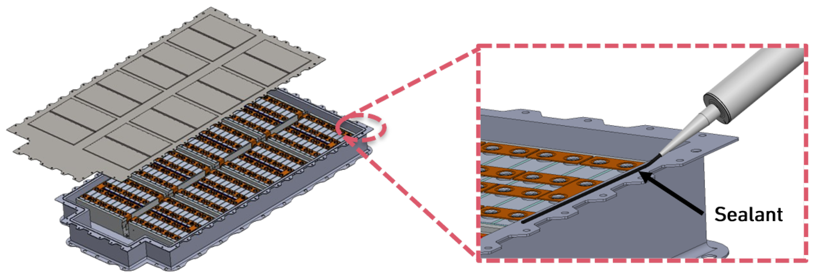
In the context of EV battery pack manufacturing, the lid-to-frame joint of a battery enclosure has particular importance. Although not intended to carry structural loads, this interface plays a decisive role in sealing the pack against moisture, dust and corrosive agents while also accommodating thermal and vibrational stresses during service [6]. Moreover, the enclosure seal must pass non-standard leak tightness tests and help mitigate the risks associated with gas venting during mechanical abuse [7]. Variabilities in pack design, the choice of substrate materials, economic constraints and performance requirements have led to diverse approaches among original equipment manufacturers (OEMs). The options range from hybrid adhesive and fastener strategies to reusable elastomeric seals, each with distinct trade-offs in manufacturability, cost, re-workability and long-term reliability [6,8]. Currently, a variety of adhesive and sealant technologies are used, such as polyurethanes (PUs), silicones and silane-modified (MS) polymers. Each solution presents trade-offs in adhesion to aluminium, resistance to temperature cycles, industrial and commercial constraints, chemical exposure and ease of disassembly for repair or recycling [6,9,10,11]. Despite the increasing industrial adoption of adhesives, a clear consensus on the best practices for lid-to-frame sealing has not yet emerged. Figure 1 illustrates the application of such adhesives in an EV battery pack, more specifically the lid-to-frame bonding.
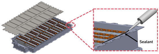
Figure 1.
Scheme of lid sealant application in EV energy storage system.
The growing emphasis on sustainability and circular economy principles has made end-of-life (EoL) management for EV battery packs, including their recycling, repair, refurbishment and second-life use, a critical consideration. One of the bottlenecks in these processes is the robust adhesive sealing of the battery enclosure, particularly the lid-to-frame joint. While this strong bond is essential for initial pack integrity, it poses a significant challenge when disassembly is required for servicing inner individual components, battery pack repair or material recovery. Current practices often involve brute-force methods, such as using hammers and chisels to pry open the lid. This results in irreversible plastic deformation and damage to the battery lid, rendering it unsuitable for reuse and necessitating the use of a new lid during reassembling. Such destructive disassembly not only increases repair costs and waste but also hinders efficient material recycling. Thus, there is a compelling need for a controlled and non-destructive debonding technique that allows the lid to be opened and re-sealed without compromising the structural integrity of its components [1,12]. Crucially, the trigger for such disassembly must be activated on demand, meaning that it should not occur inadvertently during the component’s service life but only when intentionally initiated. Furthermore, this activation stimulus must be suitable for the specific joint, ensuring its efficacy and practicality within the constraints of an EV battery pack environment. This facilitates a more sustainable and cost-effective approach to battery pack servicing and EoL management [13,14].
Provided sustainable and EoL management goals across industries and significant research into controlled disassembly methods for adhesively bonded components, recent work has explored the pulsed discharge debonding of epoxies [15], ultrasonic debonding of transducers [16], laser shock-based disassembly of composites [17] and improving reversible adhesion in vitrimers [18]. While these and other studies on debonding on demand (DoD) address different materials and triggers, they underscore a critical need for effective and non-destructive debonding solutions that are currently lacking for EV battery pack sealing joints [13].
A prominent methodology in controlled debonding uses thermally expandable agents, often referred to as thermally expandable particles (TEPs) and thermally expandable microcapsules (TEMs) [19]. These microcapsules, first patented in 1971 by Dow Chemical Company [20], consist of a thermoplastic shell encapsulating a liquid hydrocarbon core. Upon heating to a specific activation temperature, the thermoplastic shell softens, and the liquid hydrocarbon rapidly gasifies. The resulting internal pressure causes the softened shell to expand significantly, increasing its volume by 20 to 100 times its original size. This expansion within an adhesive layer generates internal mechanical stress and a localised increase in volume, leading to a cohesive failure within the adhesive, dramatically reducing the force required to separate the bonded components [21]. Crucially, debonding occurs at temperatures significantly lower than the degradation temperature of many structural adhesives, thus avoiding the thermal degradation or combustion of the primary adhesive and minimising heat exposure to sensitive components. TEPs are designed with custom expansion temperatures, typically ranging from 70 °C to 285 °C, allowing for custom debonding conditions [22]. After heat removal, the expanded particles maintain their enlarged state, facilitating easy disassembly at room temperature. While TEPs offer precise, controlled debonding, their integration and cost and the need for accurate temperature control in large-scale applications (such as EV battery packs) require careful consideration. Taking into account the typical thicknesses of the adhesive layer and the particle sizes used, the incorporation of TEPs generally leads to a reduction in joint strength [8]. Upon thermal activation, previous studies show that the post-activation strength of adhesive joints containing TEPs strongly depends on the degree of volumetric expansion. Moderate expansion produces small voids and microcracks, reducing the residual strength to roughly 15 to 50% of the original value [23]. Excess swelling causes cavity coalescence and interfacial rupture, leading to a nearly complete loss of load-carrying capacity and the spontaneous separation of the adhesively bonded joint [19,22]. Nevertheless, when formulated as a debondable primer, TEPs present an interesting solution to achieve debonding on demand in very thin localised layers, making it suitable for disassembly in critical applications.
Adhesive bonding is critical for the assembly of EV batteries, but EoL disassembly remains a significant challenge. This paper presents a comprehensive mechanical characterisation of a commercially available MS one-component (1K) adhesive, employing standard tensile, shear and mode I fracture loading conditions. A key contribution of this work is the experimental validation and detailed performance analysis of the thermally activated INDAR® 150 primer, patented and supplied by APPLUS+ RESCOLL (Pessac, France), for debonding applications, a level of investigation that has not been previously published. This research specifically targets lid-to-frame sealing joints within EV battery packs, evaluating both performance and dismantling techniques. To enable disassembly, the INDAR® 150 primer was assessed in conjunction with different adhesive families, with the critical debonding time and temperature captured in small-scale lid-to-frame separation experiments [24]. In addition, a real-scale transient thermal numerical model of an EV battery is considered to verify whether the localised heat application to trigger the debonding mechanisms of the primer is numerically suitable for the battery itself, without harming sensible components. The objective is to delineate functional requirements, material considerations and industrial practices in adhesive sealing while also identifying current limitations and future directions for the assembly of EV battery packs and EoL management.
2. Materials
A commercially available one-component MS adhesive, Teroson® 939 MS (Henkel® AG & Co. KGaA, Düsseldorf, Germany), which is commonly used for lid-to-frame bonding in EV battery packs, was selected for mechanical characterisation in order to establish a baseline. For debonding studies, a heat-activated polyamide-based primer with expandable agents, INDAR® 150 (APPLUS+ RESCOLL, Pessac, France), was used [24].
In addition to the 1K MS polymer, the effectiveness of the primer was evaluated on multiple adhesive systems, including the following:
- A two-component epoxy brittle adhesive, further mentioned as epoxy A, Araldite® AV 138 (Huntsman Advanced Materials, Basel, Switzerland).
- A two-component epoxy tough adhesive, further mentioned as epoxy B.
- A two-component polyurethane adhesive, further mentioned as 2K PU.
- A one-component polyurethane adhesive, further mentioned as 1K PU, SikaFlex® 252 (Sika Limited, Watchmead, UK).
This selection enabled the evaluation of both adhesive performance and primer-assisted debonding behaviour in several commercially relevant adhesive formulations. The substrate materials used were high-strength steel (HSS) and 6082-T6 aluminium alloy.
3. Methodology
This work was divided into two parts, the first being the mechanical characterisation of the adhesive and the second the assessment of the heat-activated primer. In regards to the mechanical characterisation of the adhesive, this was divided into bulk material strength tests and fracture mechanics tests. Bulk tensile tests were conducted to determine the tensile properties of the adhesive. Shear performance was evaluated using the thick adherend shear test (TAST). Fracture behaviour was assessed via mode I Double Cantilever Beam (DCB) tests to estimate the critical energy release rate. In addition, single-lap joints (SLJs) were manufactured to measure joint lap shear strength (LSS), and small-scale lid-to-frame pull-out tests were performed under conditions similar to those for SLJs to assess practical joint performance.
3.1. Specimen Manufacturing
3.1.1. Bulk Tensile Specimens
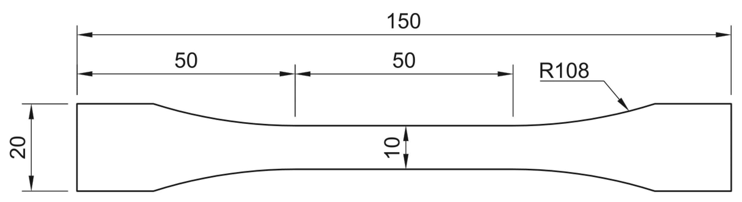
Bulk tests were carried out to determine the tensile properties of the adhesive, including Young’s modulus, ultimate tensile strength and elongation at breakage. To prepare the specimens the adhesive was injected directly into a 3 mm thick mould with the final coupon shape following the NF T 76-142 standard, displayed in Figure 2 [25,26].
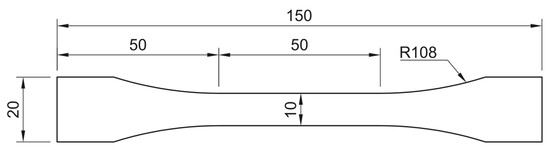
Figure 2.
Bulk specimen drawing (dimensions in mm).
3.1.2. Thick Adherend Shear Specimens
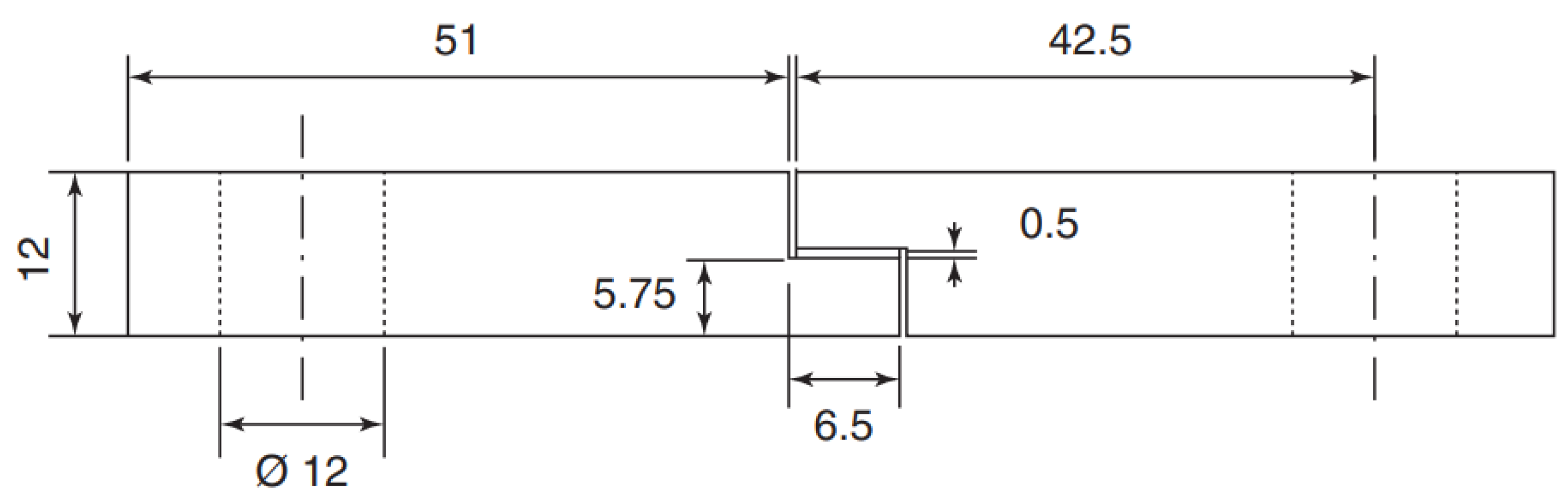
A custom-designed mould was used to fabricate six TAST specimens. Each specimen was produced with an adhesive layer of approximately 0.5 mm thickness. The inclusion of shims with 1.5 mm of thickness ensured the accurate control of the adhesive overlap of 5 mm and minimised the introduction of undesirable tensile stresses during testing. For quality assurance, the adhesive thickness of each pair of specimens was measured using a micrometer with a precision of 0.01 mm. The final geometry of the specimens was in accordance with the machined adherends to ISO 11003-2 standards, as illustrated in Figure 3 [27]. The TAST DIN 40CrMnMo 8-6-4 steel adherends with a 25 mm width were shotblasted and degreased with acetone prior to adhesive application.
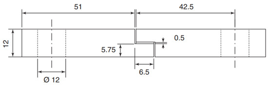
Figure 3.
TAST specimen drawing (dimensions in mm).
3.1.3. Double Cantilever Beam Specimens
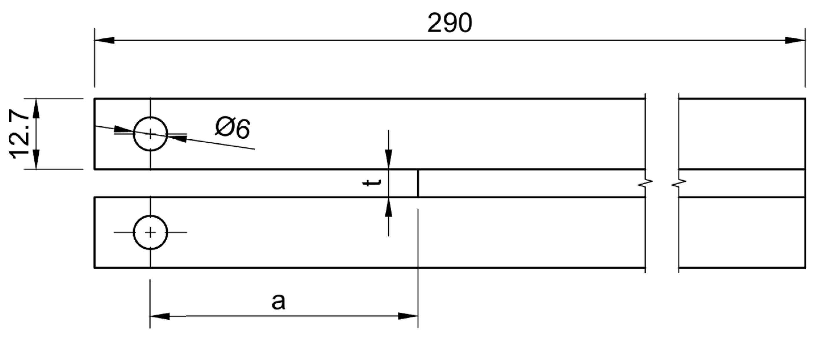
DCB specimens were fabricated to investigate the fracture behaviour of the adhesive under a mechanics-based framework. Adherends with drilled holes were manufactured from DIN 40CrMnMo 8-6-4 steel and used to evaluate the critical strain energy release rate (mode I fracture toughness). The energy release rate was determined from the load–displacement data obtained during the test, with crack growth carefully monitored throughout the experiment. The geometry of the specimen followed the ASTM D3433-99 specifications, as illustrated in Figure 4 [28]. The adherend surfaces were sandblasted and degreased with acetone. The adhesive thickness (t) was controlled to 0.20 mm by placing calibrated tape along both edges of the specimen. An artificial crack starter was introduced using a 0.10 mm razor blade fitted with two 0.05 mm calibrated tapes, resulting in an initial crack length () of 50 mm. In addition, a 0.20 mm tape strip was positioned at the far end of the specimens to maintain a uniform geometry [9,26].
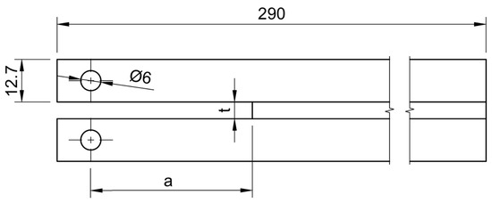
Figure 4.
DCB specimen drawing with a thickness of 0.2 mm and an initial crack of 50 mm (dimensions in mm).
3.1.4. Single-Lap Joints
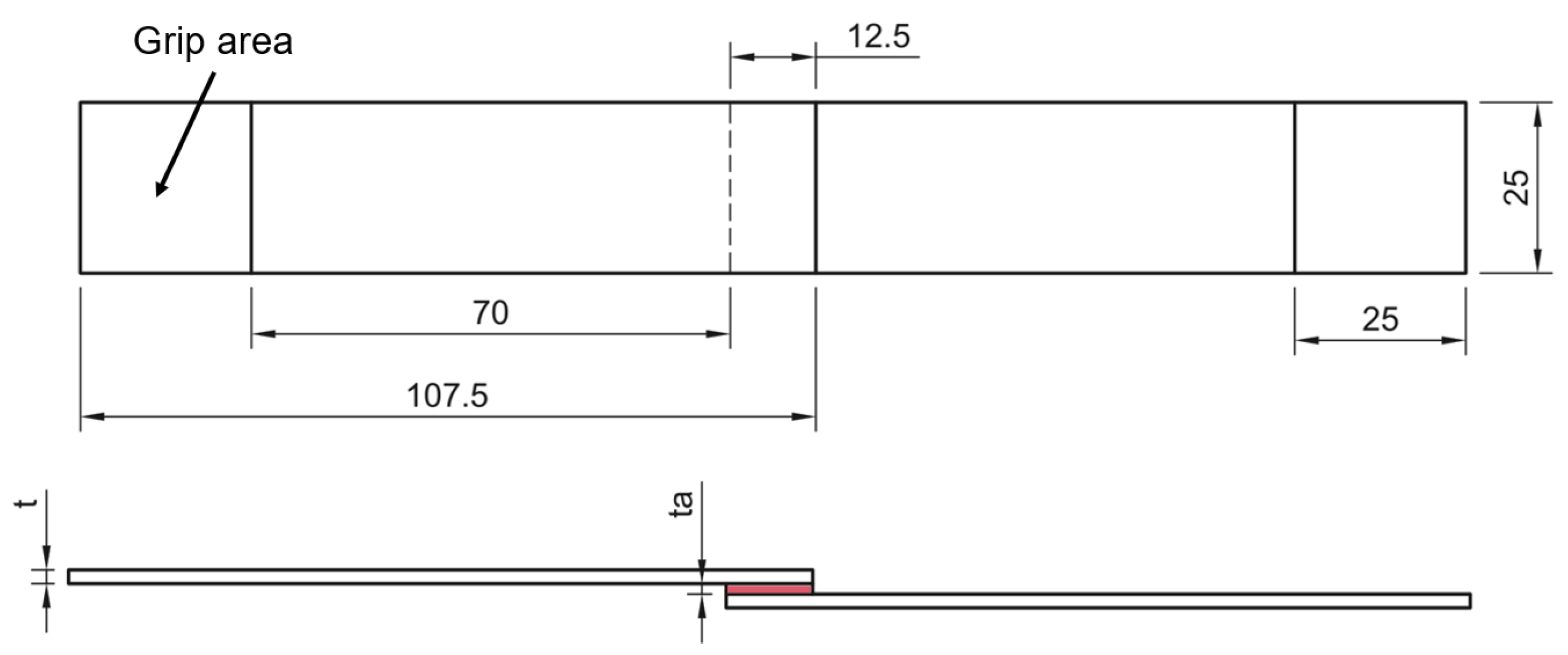
SLJ specimens were produced following ASTM D1002 standard. Each joint was designed with an overlap length of 12.5 mm, as illustrated in Figure 5 [29]. A uniform 0.25 mm thick adhesive layer was maintained in all specimens. The steel adherends had a thickness of 2.25 mm, while the aluminium adherends were 2.0 mm thick. To ensure consistent bond quality, the joints were assembled in a precision mould and placed under a hydraulic press during curing [26].
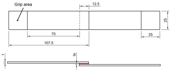
Figure 5.
SLJ specimen drawing (dimensions in mm).
3.1.5. Debonding Evaluation Tests
To assess the compatibility and performance of the debondable primer, the use of four categories of adhesive systems in a standardised joint configuration was investigated. Specifically, two 2K epoxy systems, one 2K PU system, one 1K PU system and the previously characterised 1K MS adhesive were selected as benchmark materials. Lap shear specimens with an overlap of 12.5 mm were prepared and tested with and without the primer layer to evaluate its influence on joint strength and debonding behaviour. Epoxy-based adhesives, a brittle epoxy A and a tough epoxy B, were tested using HSS substrates to minimise peel stresses and ensure predominantly shear loading. The steel substrates were sandblasted and degreased with acetone prior to either primer or adhesive application. In contrast, the 6082-T6 aluminium alloy was used as the substrate material for the PU and MS systems, reflecting their typical application environments and providing a comparative evaluation of the effectiveness of the primer in different adhesive chemistries. For aluminium joints, only acetone degreasing was used to better approximate a real joint scenario [8].
For joints incorporating the primer, the application procedure involved soaking a clean sponge with the primer solution and uniformly rubbing it once across the substrate surface in a single linear motion. The coated substrates were then allowed to dry under ambient conditions for approximately 10 min prior to adhesive application.
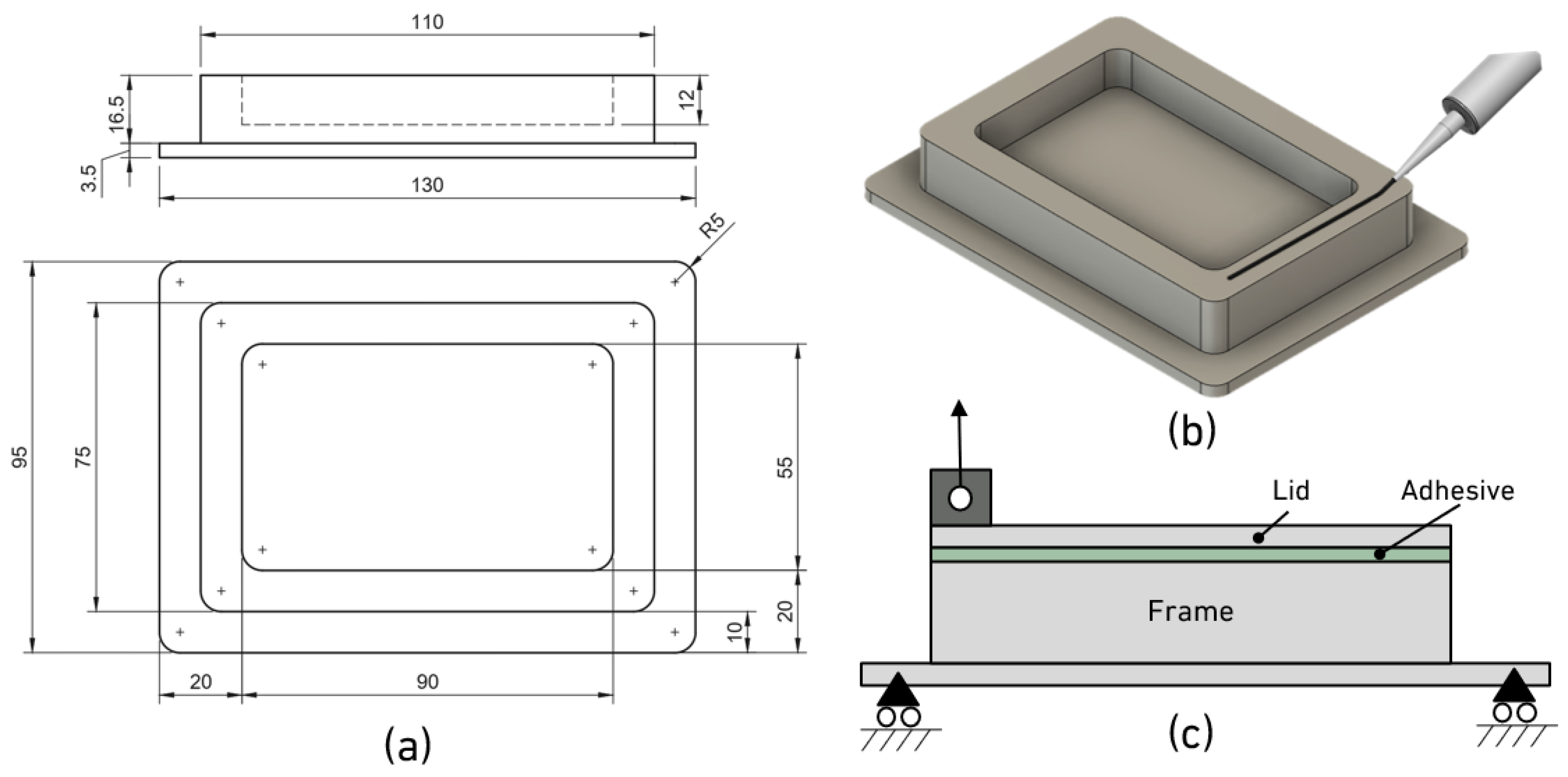
The debonding evaluation tests were conducted on two different scales: the joint scale and the small-scale. For the joint scale, lap shear joints were heat-triggered and evaluated to assess the performance of the debondable primer. To further validate the applicability of the primer in realistic geometries, a small-scale structural demonstrator was fabricated, consisting of a CNC-machined Al 6082-T6 battery frame and lid assembly (Figure 6). The adhesion thickness of 0.2 mm was controlled by a fishing thread.
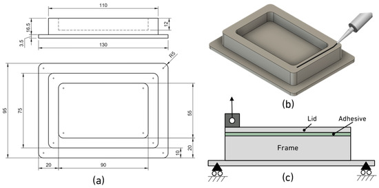
Figure 6.
Small-scale specimen, representative of battery frame for lid sealant application: (a) technical drawing of small-scale battery frame (dimensions in mm); (b) 3D view of adhesive application; (c) assembled small-scale joint in place for pull-out test.
3.2. Testing Procedures
3.2.1. Mechanical Characterisation Tests
All experiments were conducted under quasi-static conditions at room temperature (23 °C) using an INSTRON® 3832 test machine (INSTRON, Norwood, MA, USA) equipped with a 30 kN load cell. Digital image correlation (DIC) measurements were captured with a Canon EOS M5 camera (Canon Inc., Tokyo, Japan), fitted with a Canon® EF-M 18 to 55 mm F/3.5 to 5.6 lens. DIC analysis was performed using GOM Correlate® software (2019 version).
Bulk tensile tests were performed at a constant crosshead speed of 1 mm/min. The strain field was obtained using DIC, as the use of a physical extensometer not only would restrict the measurable strain range but could also introduce undesired stresses in the dog-bone specimens. Similarly, TAST specimens were tested with the same loading rate of 0.5 mm/min, with the shear strain distribution evaluated using DIC analysis [9]. Both the tensile and shear specimens were coated with matte white paint and then speckled with black ink to produce a suitable speckle pattern for the DIC analysis. Bulk tensile specimens were painted with a more ductile polyurethane-based paint to prevent paint cracking during the test, ensuring the accurate tracking of the specimen under high elongation. At least three bulk and TAST specimens were considered to support the statistical consistency of the results.
DCB tests were performed at a constant speed rate of 0.2 mm/min. To allow for an accurate determination of the fracture energy, the rotations at the loading points were monitored with a pair of Sick® TMS22E-PKH080 inertial sensors (Sick, Waldkirch, Germany) that operate as inclinometers. These devices were synchronised with the universal testing machine to ensure temporal consistency between the load and angle measurements. The acquired data provided the basis for the application of a J-integral formulation to quantify the mode I fracture energy for each test. For a rectangular section DCB subjected to mode I loading, the J-integral is expressed as follows [30]:
This formulation remains valid due to the path independence of the J-integral, which applies to both linear and nonlinear elastic materials, provided that regions outside the fracture process zone (FPZ) deform elastically during crack propagation. To ensure the reliability of the methodology, at least three DCB specimens were analysed for each condition, allowing the repeatability of the results to be assessed.
SLJ were tested with alignment tabs at a rate of 1 mm/min and at least three specimens were considered per condition.
3.2.2. Debonding Tests
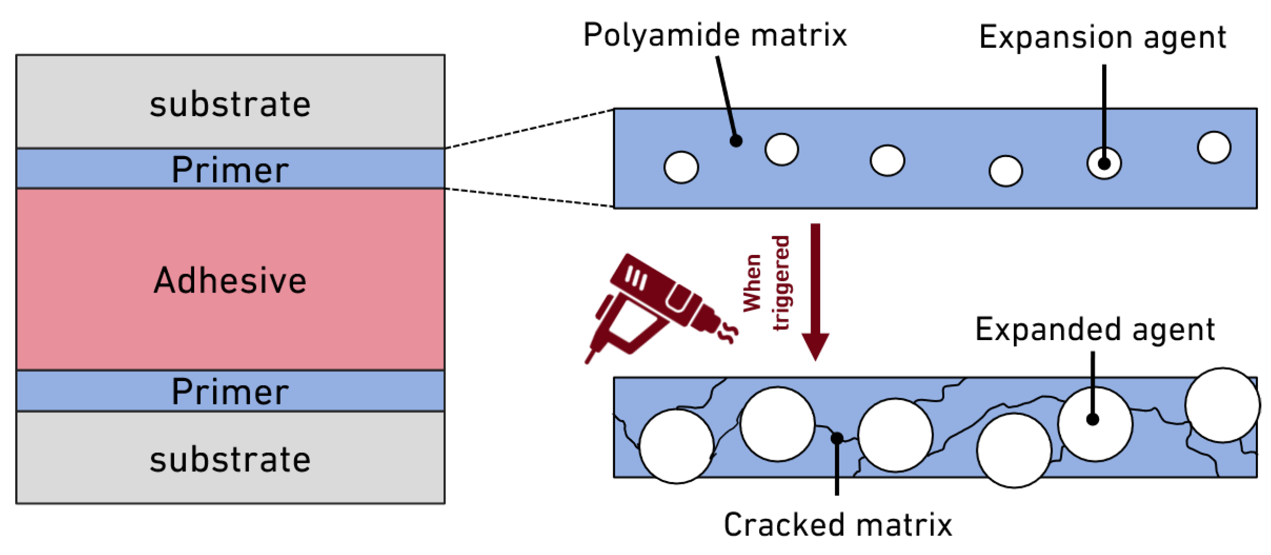
The heat-triggering primer has an irreversible mechanism, which means that once the TEPs dilate, they will not reduce to their original size [19,21]. In fact, the expansion of the TEPs in the thin primer layer leads to a strongly foamed layer, with low cohesion, decreasing the strength of the primer layer. The primer is set to be activated at 150 °C, which means that after the heating stage, the joints can be disassembled at room temperature, thus it is not required to disassemble at 150 °C, as illustrated in Figure 7.
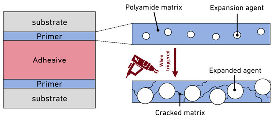
Figure 7.
The behaviour of the heat-activated primer upon reaching the triggered temperature.
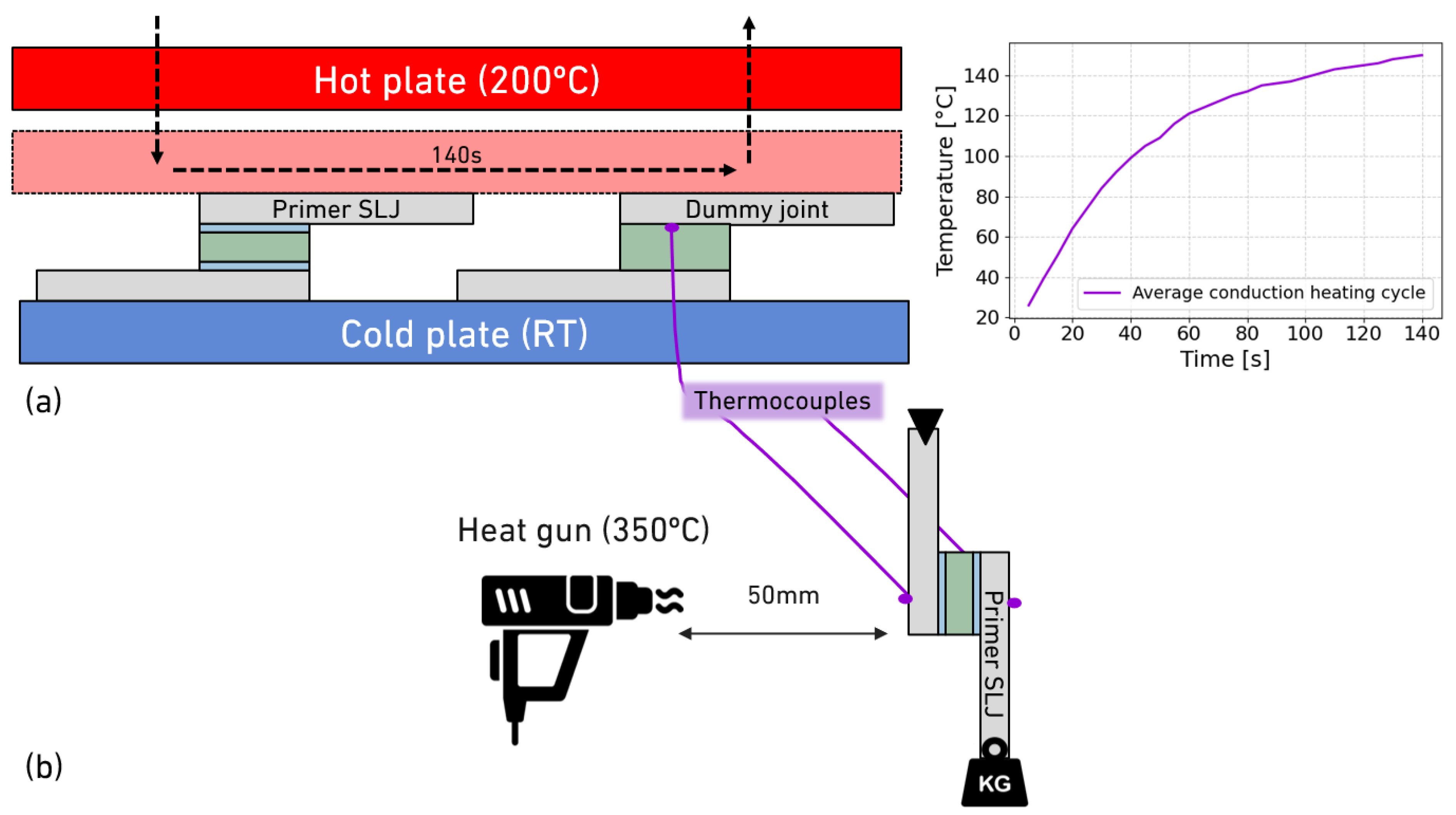
To evaluate the performance of the heat-activated debondable primer, two complementary approaches were adopted: a laboratory-scale lap shear test and a small-scale structural demonstrator test. In the first approach, lap shear joints were prepared and subjected to two distinct debonding procedures to assess the thermal response and disassembly behaviour of the primer. Both methodologies are illustrated in Figure 8. The lap shear joints in which the debonding trigger was performed were tested on the same quasi-static test machine but equipped with a 1 kN load cell to accurately assess the residual joint strength. More specifically, the procedures used in this work were as follows:
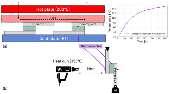
Figure 8.
Heating processes for disassembly: (a) conduction heating using hot plates and typical heating ramp for SLJs; (b) in situ convection heating via heat gun.
- In situ heating with suspended load: Debonding was initiated using convective heating, while a constant load was applied to the joint. A suspended mass of 0.5 kg was attached to each sample, and hot air was directed at 350 °C to the joint using a heat gun. The objective was to determine the temperature, heating rate and time required to achieve separation under thermal activation. Two thermocouples were positioned at the front and back of each specimen to monitor the temperature distribution. The primer exhibited a dual debonding mechanism: the softening of the polyamide (PA) matrix near its melting or softening temperature and volumetric expansion of the TEPs, both contributing to a strong reduction in the cohesion of the primer layer and debonding in the primer layer.
- Post-heating residual strength evaluation: In the second procedure, the joints were subjected to conductive heating using a hot press, following a two-minute heating ramp to reach 150 °C. After heating, the specimens were immediately removed, cooled to room temperature and subsequently tested to measure their residual shear strength. This method provided insights into the expansion kinetics of the TEPs of the primer and the influence of the heating ramp on bond degradation.
Following the heat-triggering procedure, pull-out testing was employed to measure the force required for disassembly. A 20 by 20 mm cross-sectional 25 mm long loading block was attached to the 2 mm aluminium lid using a 2K epoxy system, Araldite® 420 A/B, (Huntsman Advanced Materials, Basel, Switzerland). This block acted as the gripping interface for the pull-out test, which was conducted at a speed of 1 mm/min. The small battery frame apparatus was constrained to a single degree of freedom during testing, as shown in Figure 6. This methodology allowed for a practical comparison of the primer’s performance in conditions representative of those encountered in EV battery pack modules. In all cases, at least three specimens were tested.
3.3. Thermal Model of Lid Heating
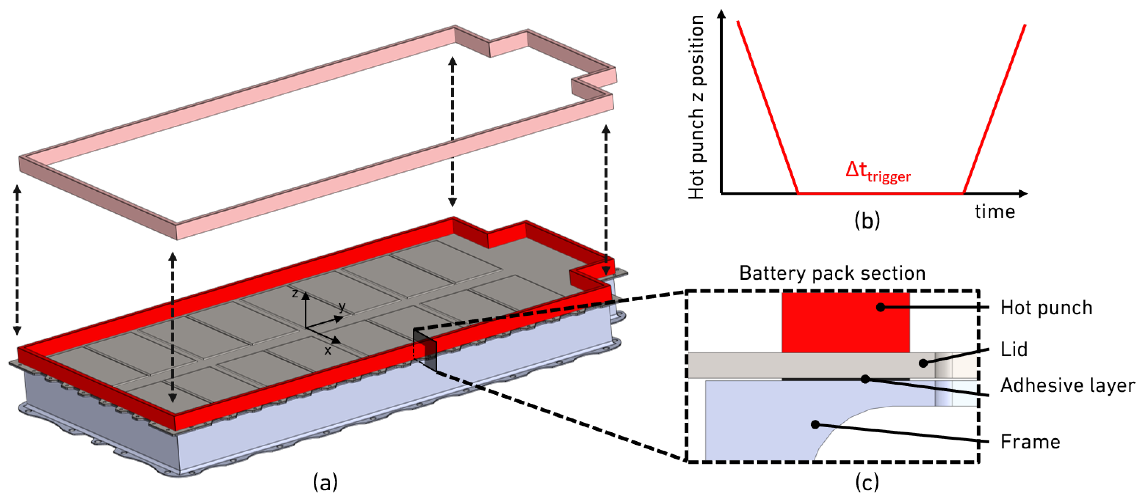
To validate the thermal safety and feasibility of the localised heating disassembly strategy, a three-dimensional finite element thermal transient analysis was conducted in a 3D model of a first-generation BMW i3 battery pack in SOLIDWORKS software (version 2024) using the internal FEA solver. For this, four main parts were established, similarly to Figure 1: a battery frame; a lid with 3 mm thickness; an adhesive layer with 12.5 mm width and 0.3 mm thickness; a hot punch, with the same width as the adhesive layer, which will serve to conduct heat to the top part of the lid. The adhesive layer used is a representative layer since the actual joint contains a thin primer layer on each substrate. Both the primer and adhesive layer have similar polymeric thermal properties, thus it is appropriate to consider a representative layer model with adhesive properties. The material properties considered are listed in Table 1, for the lid, hot punch and battery frame from the same aluminium alloy [32,33]. The heating procedure was performed in a simplistic way, simulating the conduction heating process explained in Figure 8, in which a top punch is preheated at 200 °C, a value 50 °C higher than the required triggering temperature, comes in contact with the top face of the battery lid. The initial room temperature was set at 23 °C, in which a time step of 200 s was considered, with a step resolution of 1 s and a specific tolerance of 0.01 °C. The mesh was moderately refined at critical interfaces to capture thermal gradients accurately. The adhesive layer, being the smallest and most thermally sensitive component, was meshed with 0.15 mm element sizes. The surrounding aluminium frame and lid were trimmed with element sizes of 1 to 2 mm to balance accuracy and computational efficiency. The punch was trimmed with coarser elements (5 to 10 mm). The total mesh consisted of approximately 140 thousand tetrahedral elements.

Table 1.
Summary of material properties used in the thermal transient model.
As a concept, the thermal model was designed with conditions in mind similar to what could happen in a repair shop to disassemble the battery lid, in which a hot punch comes in contact with the overlap bonded area and triggers the primer mechanism via heat conduction. As denoted in Figure 9, the punch comes into contact with the lid for a certain time and is then removed, letting the lid cool, making it possible to easily disassemble it right after the punch is withdrawn or after the lid reaches room temperature, requiring a lower force.
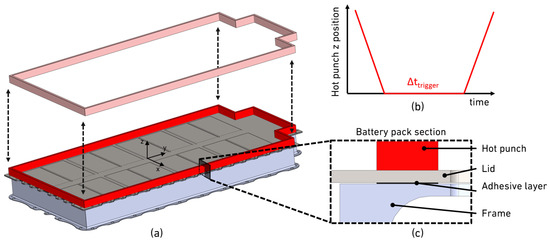
Figure 9.
Lid conduction heating concept: (a) sequence of heat punch contact with first-generation BMW i3 battery pack; (b) hot punch position in relation to lid surface; (c) section along plane of lid to frame bonding.
4. Results
4.1. Mechanical Characterisation
4.1.1. Tensile Test
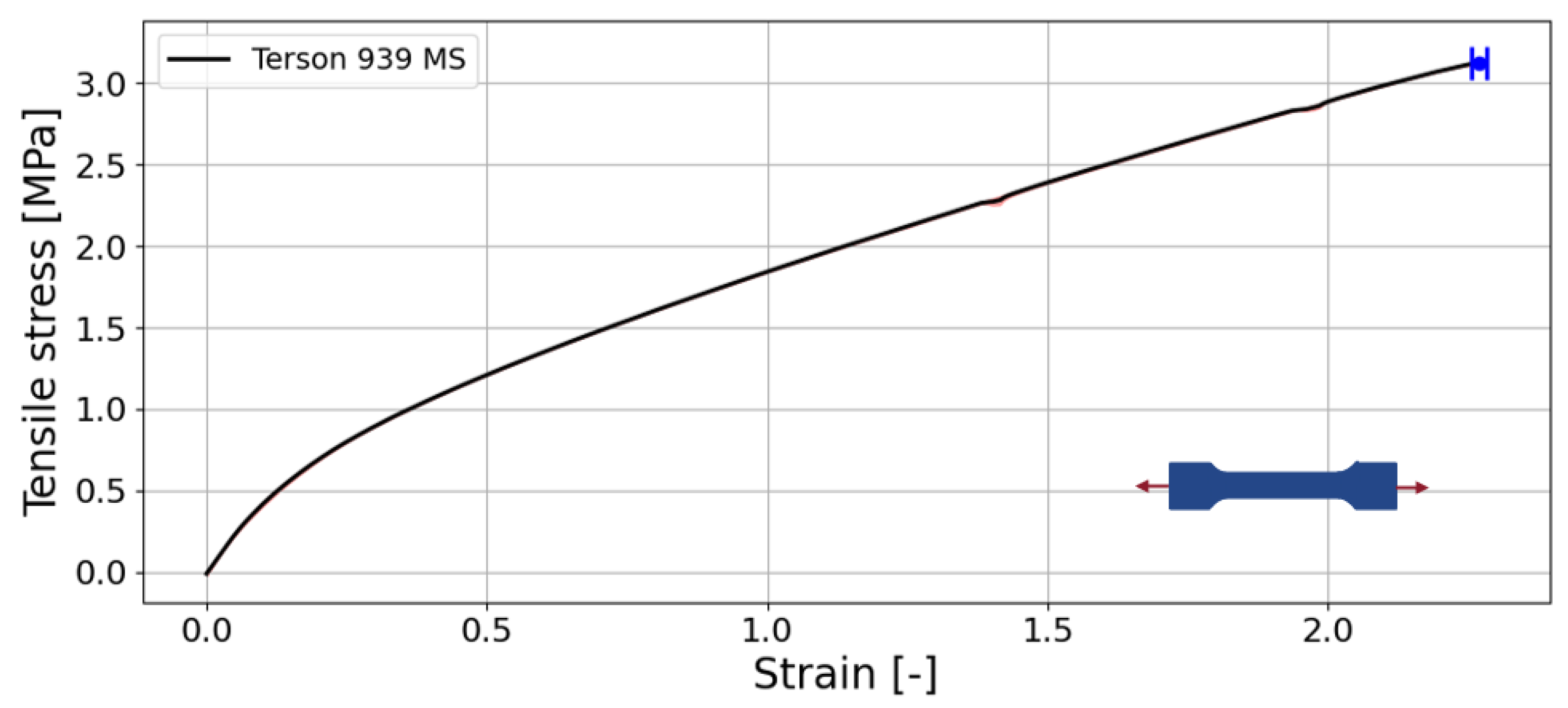
Figure 10 shows the stress–strain curve for the bulk tensile MS adhesive. The material exhibits hyperelastic behaviour, characteristic of flexible polymers like silicones, MS adhesives and other rubber-like materials [9,34]. In small deformations, the stress slightly increases under high strains, indicating a low initial stiffness.
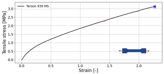
Figure 10.
Tensile stress–strain curve for 1K MS adhesive.
The adhesive demonstrates exceptional ductility, reaching strain levels exceeding 230% before failure. The maximum tensile stress reaches approximately 3.1 MPa, a value consistent with typical single-component MS polymer systems, demonstrating high energy absorption. The smooth continuous stress–strain curve and the absence of a sharp stress drop at the end of the test indicate a ductile failure mode rather than a brittle fracture. A Young’s modulus of 2.9 MPa was reported. The stress–strain response of the MS 1K adhesive under uniaxial tension shows an initially steep slope that gradually decreases with increasing strain, indicating progressive softening. The high initial modulus arises from the combined stiffness of the crosslinked polymer network, filler–matrix interactions and reversible physical associations [35,36]. As deformation proceeds, these interactions progressively rupture or relax, and load transfer shifts to the more compliant polymer backbone. This leads to a reduction in the tangent modulus and a characteristic soft, ductile response typical of MS polymer adhesives [37].
4.1.2. Thick Adherend Shear Test
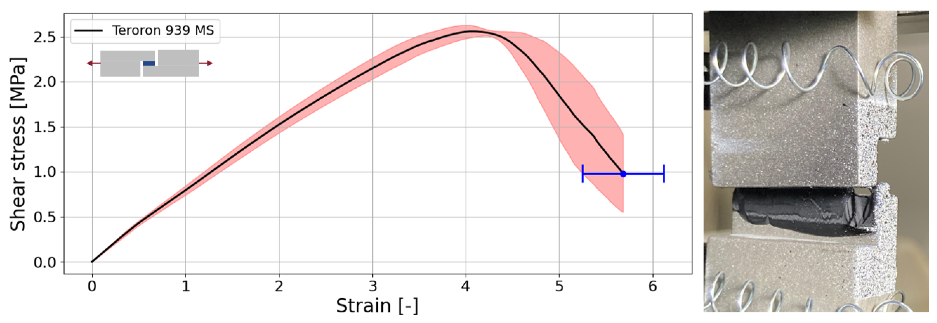
Figure 11 presents the TAST results for the 1K MS adhesive. The test exhibits a more linear stress–strain response up to failure compared to bulk tensile specimens. The failure is not brittle because some adhesive remains attached within the overlap region, consistent with the high ductility of the polymer. A shear modulus of 0.94 MPa was determined, which corresponds to a Poisson ratio of 0.35, calculated using the isotropic material relationship. The adhesive demonstrated a shear strength of 2.6 MPa, all joints failing cohesively in the adhesive and a strain to failure of approximately 550%.
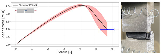
Figure 11.
Shear stress–strain curve for 1K MS adhesive.
4.1.3. Double Cantilever Beam Test
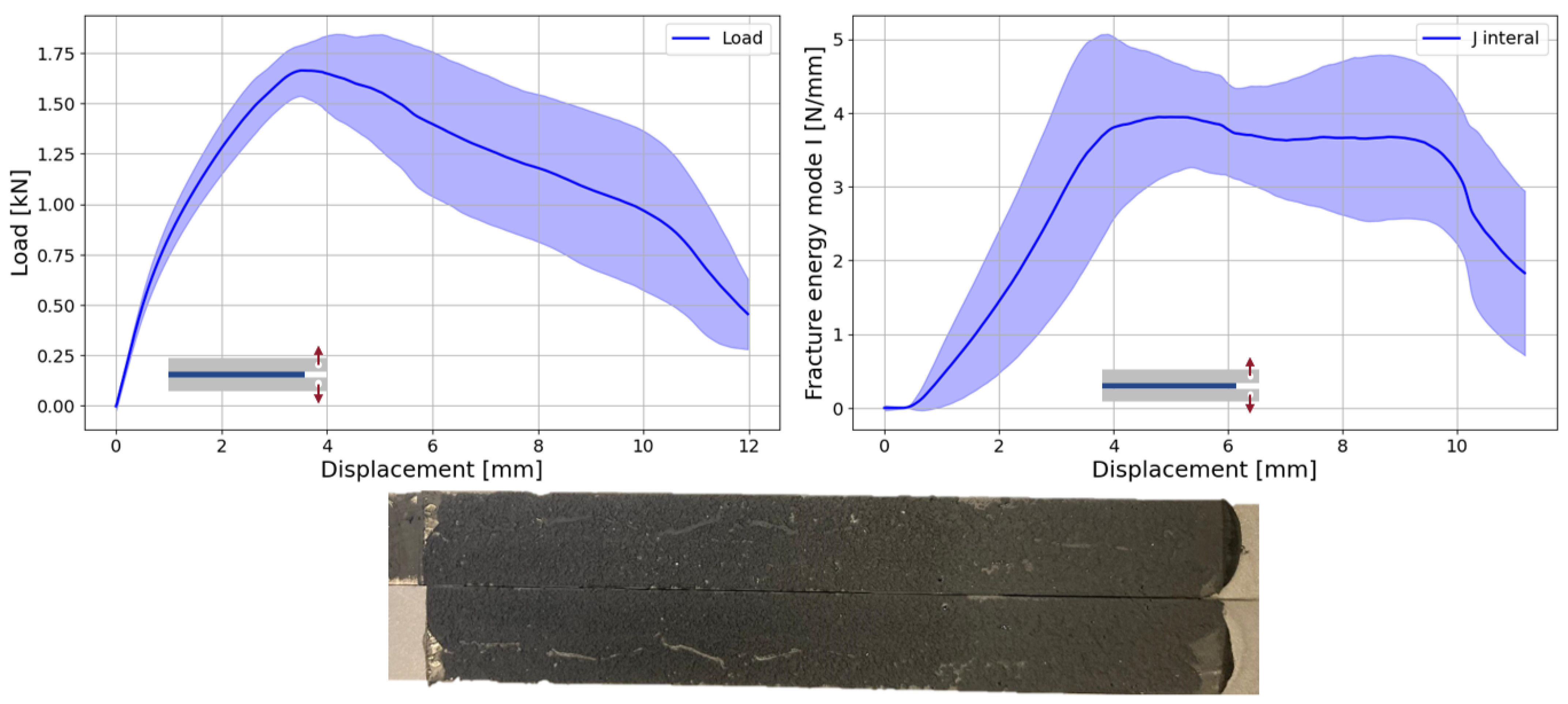
The DCB test results are presented in Figure 12. Despite the notable data scatter, which is typical for highly compliant, rubber-like adhesives, a well-defined plateau was observed in the J-integral R-curve. The plateau corresponds to a mode I critical energy release rate, , of 3.95 N/mm. This relatively high value is consistent with the inherent high ductility of the material, leading to a large fracture process zone (FPZ) and significant resistance to crack initiation and propagation. The extensive FPZ indicates that energy dissipation occurs over a broad region ahead of the crack tip. This behaviour is characteristic of MS polymer adhesives and contributes to their high toughness and tolerance to damage in bonded joints. Furthermore, the plateau in the R-curve suggests stable crack growth, highlighting the material’s capacity to support the load under increasing displacement without catastrophic failure. All specimens showed cohesive failure in the adhesive layer.
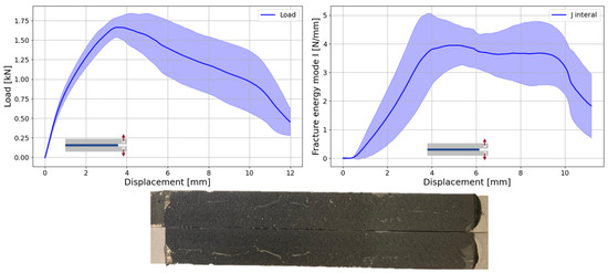
Figure 12.
Load–displacement (left) and J-integral curve (right) for 1K MS adhesive as well as DCB typical mode of failure (bottom).
Table 2 summarises the mechanical properties of the 1K MS lid sealant adhesive.
Table 2.
Summary of mechanical properties of 1K MS lid sealant adhesive.
4.2. Debonding Evaluation
As mentioned above, the debonding technique explored involves the application of a heat-triggered primer layer to allow for easy disassembly on command. The formulation of the debondable primer primarily comprises a polyamide or copolyamide matrix combined with a thermally responsive expansion agent. The polyamide component, typically soluble in low-molecular-weight alcohols such as ethanol or benzyl alcohol, provides the continuous phase and mechanical stability of the primer. The expansion agent, such as TEMs, induces localised mechanical stress upon heating, promoting expansion within the matrix and subsequent interfacial weakening.
A notable advantage of this system lies in its clean removability. Following separation, the residual primer can be easily removed using alcohol-based solvents such as isopropanol, leaving the substrate surfaces intact and suitable for reuse.
4.2.1. Joint Performance
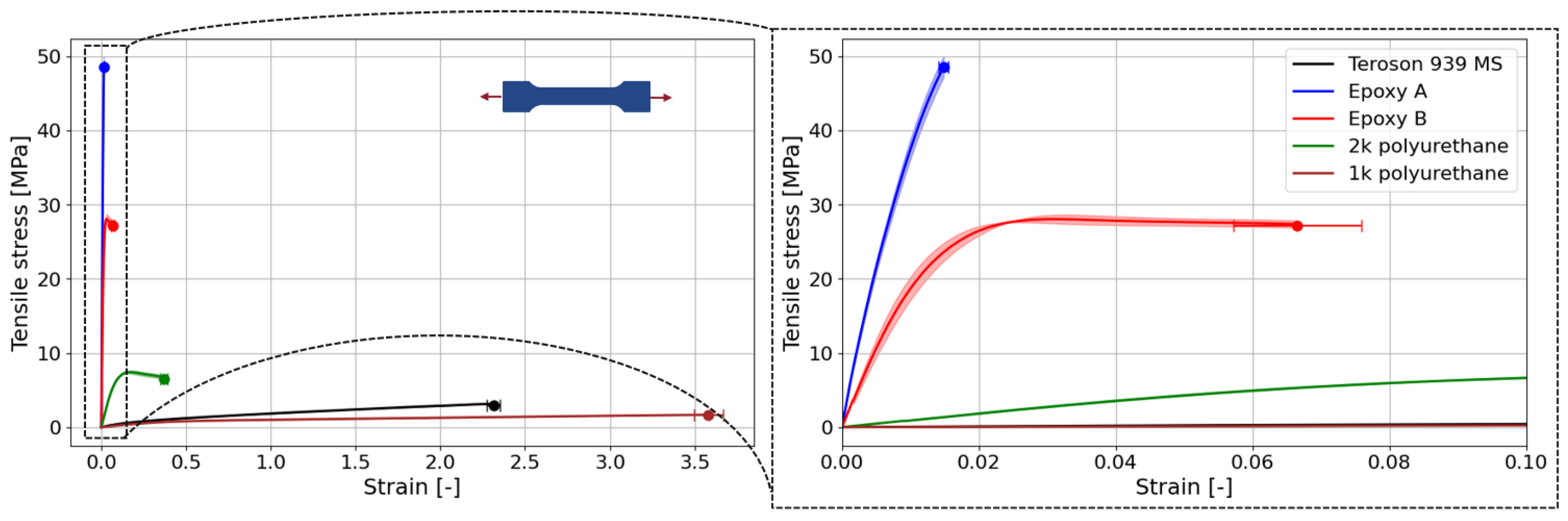
To provide a comprehensive understanding of how the debonding primer interacts with different adhesive chemistries, we characterised the fundamental mechanical properties of the various adhesive systems employed in this study. Figure 13 presents the bulk tensile stress–strain curves for the MS adhesive; two epoxy systems, epoxy A [38] and epoxy B [39]; and the two PU adhesives (1K and 2K). This selection represents a range of adhesive behaviours, spanning from highly structural brittle and tough epoxies, with ductilities from 1.5% to 7% and 30 to 50 MPa in tensile strength, to more flexible non-structural applications, up to 350% and 2 MPa, which allows for an evaluation of the primer’s effectiveness across various adhesive properties.
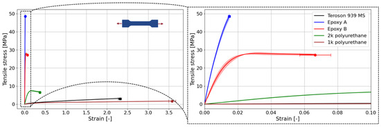
Figure 13.
Tensile stress–strain curves for all the adhesives studied in terms of primer joint compatibility and performance.
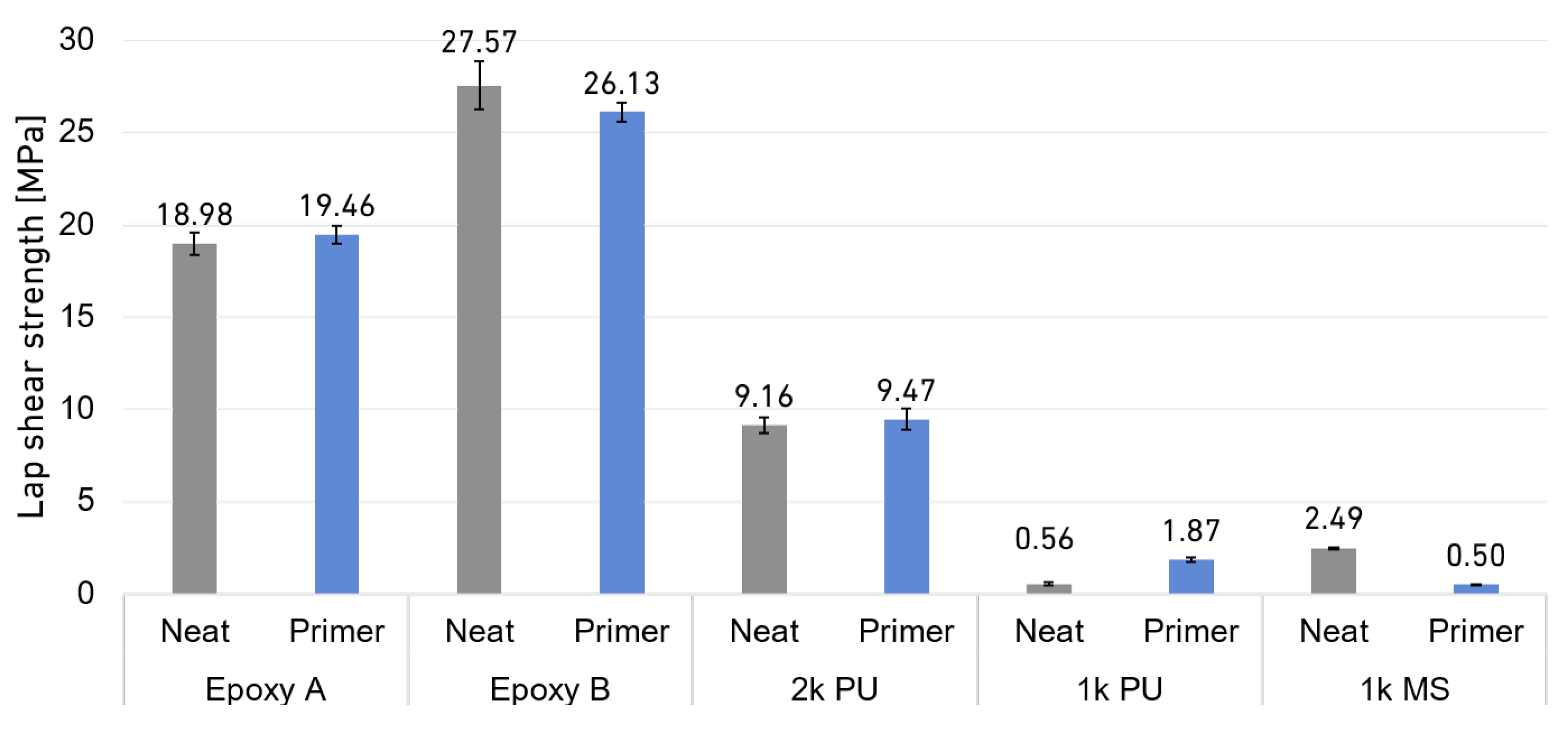
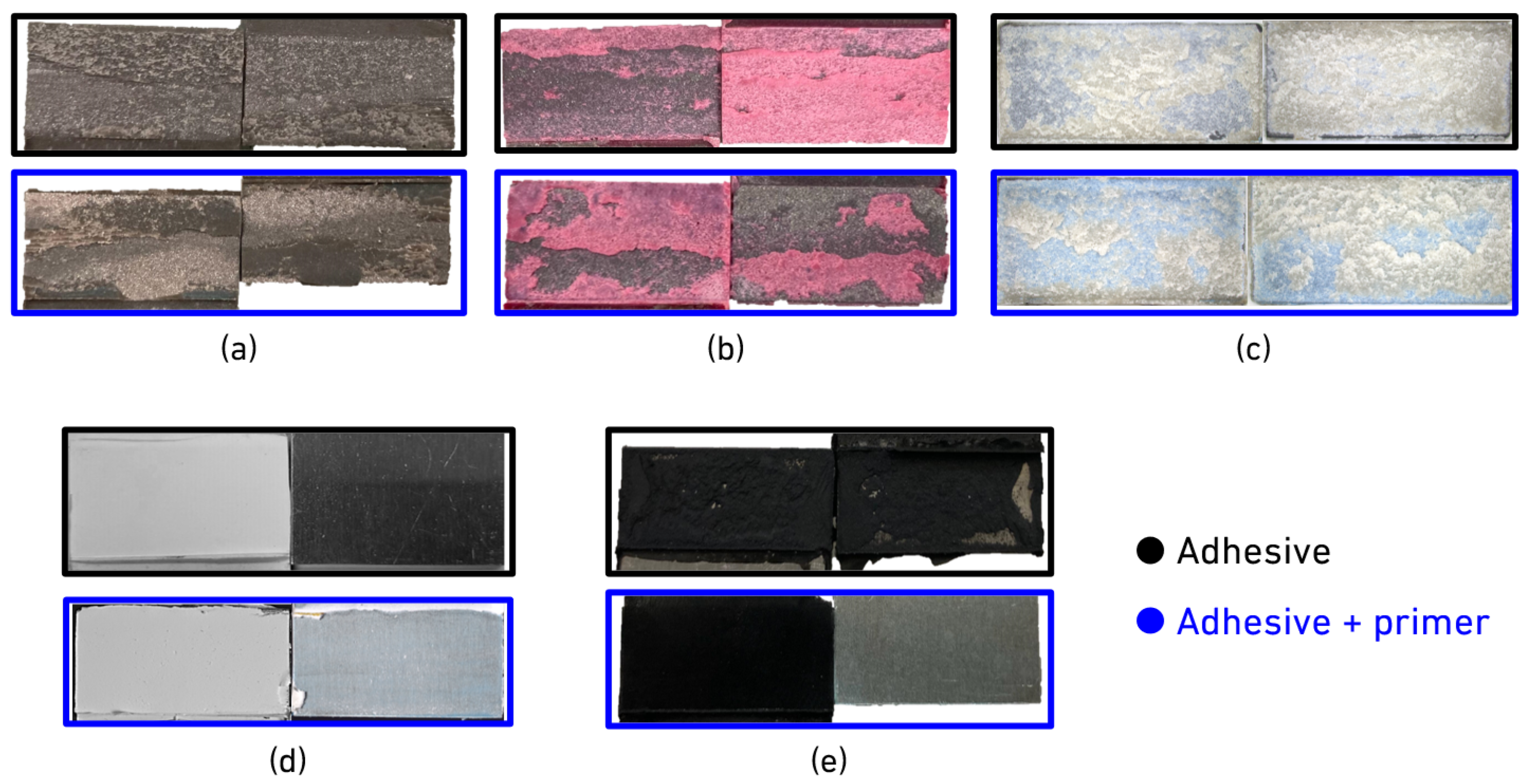
To evaluate the compatibility of the primer, the lap shear joints were neatly tested and also evaluated with the primer to assess the final strength and mode of failure, since the application of the debondable primer induces two new interfaces, substrate to primer and also primer to adhesive. Figure 14 and Figure 15 show the lap shear strength of all configurations and the modes of failure, respectively, also presented in Table 3.
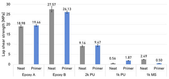
Figure 14.
Summary of LSS of all SLJ configurations with and without thermally activated primer.
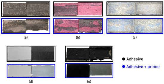
Figure 15.
Typical failure modes for all the SLJ configurations: (a) epoxy A; (b) epoxy B; (c) 2K PU; (d) 1K PU; (e) 1K MS.
Table 3.
Summary of lap shear joint strength for neat and adhesive and primer conditions (values in MPa).
Both tested epoxy systems exhibited cohesive failure within the adhesive layer. The epoxy A system with the primer showed a minor component of mixed failure, involving the primer and the substrate, along with cohesive failure. Despite this mixed failure mode, the LSS of the epoxy A system remained comparable to that of the neat adhesive, suggesting that its inherent brittleness may limit its ultimate strength in lap shear joints, particularly when peel stresses are concentrated at the overlap edges [40]. In contrast, epoxy B achieved a superior LSS of 28 MPa. Although primer treatment resulted in a slight reduction in strength, the failure modes remained largely consistent, showing cohesive failure within the adhesive and mixed failure between the primer and the substrate. This indicates good compatibility and adhesion enhancement provided by the primer for this formulation. Regarding PU adhesives, the 2K PU system joints demonstrated cohesive failure, producing similar lap shear strengths regardless of primer application. However, the neat 1K PU system exhibited adhesive failure between the adhesive and the substrate. This observation aligns with the typical requirement for substrate pre-treatment or primer application to enhance adhesion for 1K PU adhesives. With the application of the primer, the adhesion of the 1K PU system was significantly enhanced, increasing approximately four times, and the failure mode transitioned from adhesive to cohesive failure within the adhesive itself. Interestingly, when tested with the MS polymer adhesive, the neat joint achieved an LSS of 2.5 MPa, but the joint with primer treatment showed a decrease in LSS of 0.5 MPa. Furthermore, the failure mode shifted to interfacial failure between the adhesive layer and the primer. It was observed that the MS adhesive could easily be peeled from the cured primer, indicating poor adhesion between the adhesive and the primer itself.
4.2.2. Dismantling
The heat-activated primer operates through an irreversible mechanism: once the TEPs expand, they do not contract back to their initial dimensions. This expansion disrupts the surrounding matrix, giving a strongly expanded primer layer, with very low cohesion, significantly weakening itself. Because the primer is designed to activate at 150 °C, the bonded components can be separated at room temperature after heating, meaning that disassembly is not required while the joint is still at the required triggered temperature.
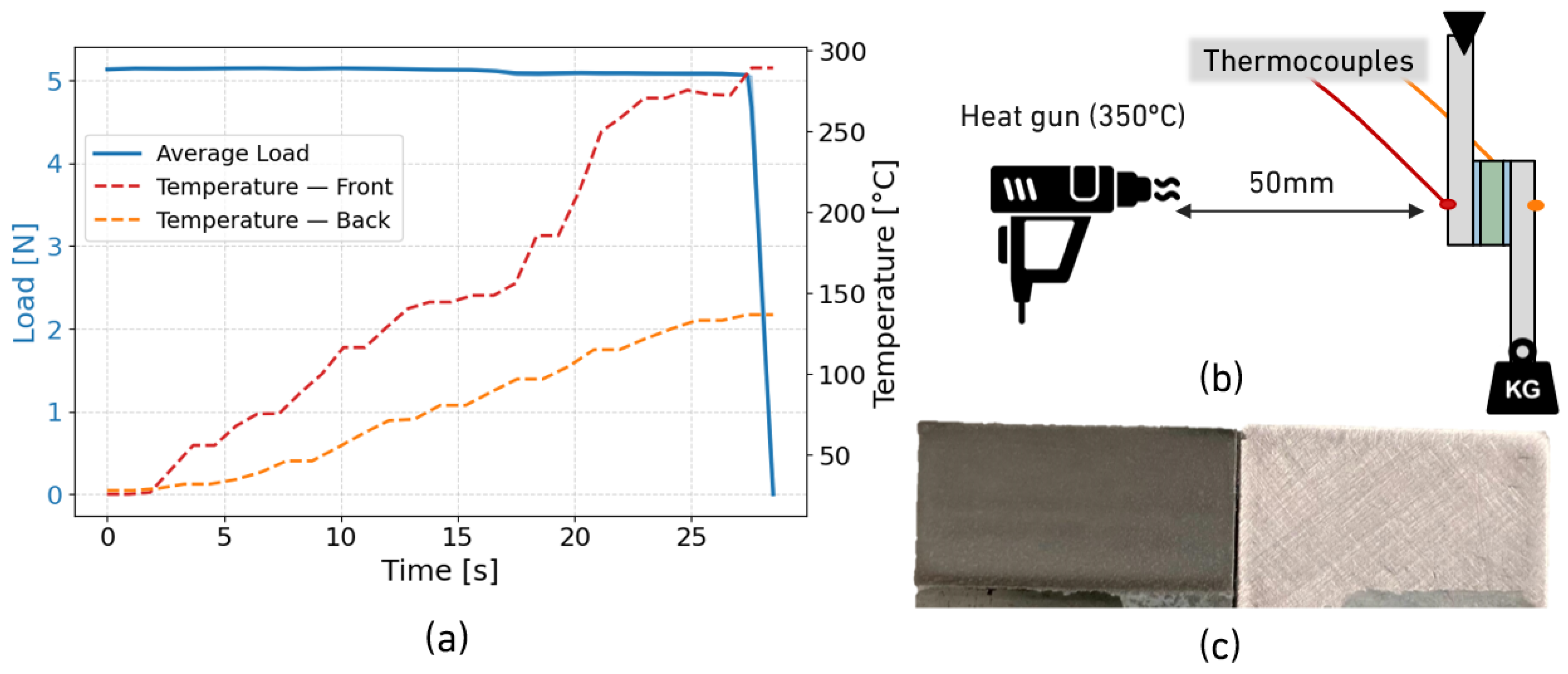
The first heating method assessed was in situ convection, in which the SLJ specimen was connected to the load cell of the quasi-static machine while a constant weight was applied to the lower substrate. The heat gun provided convective heating and reduced the cohesive strength of the primer through two primary mechanisms: the softening of the PA matrix as the temperature approached its softening point and the activation of expandable agents. This process constitutes in situ debonding, meaning that the failure of the sample is expected solely from the applied suspended mass once the primer sufficiently weakens. Debonding occurred consistently in less than 30 s, as shown in Figure 16. The failure mode was interfacial between the primer and the substrate, leaving the adherends free of adhesive residue.
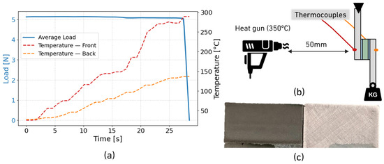
Figure 16.
Convection heat disassembly strategy: (a) load–displacement curves and joint temperature evolution; (b) apparatus scheme; (c) typical failure mode of SLJ with 2K PU.
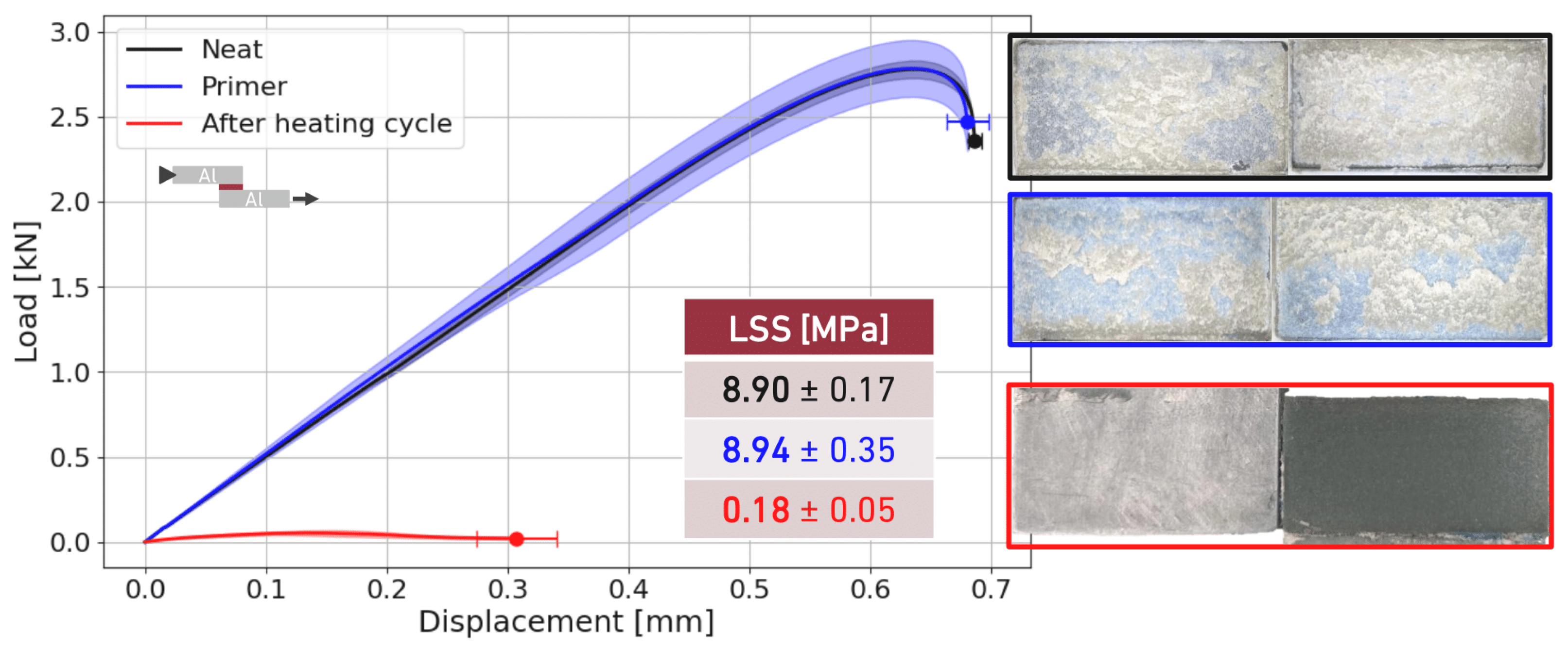
Given the intended application of this technology for lid-to-frame bonding in EV battery packs, it would not be practical to apply mechanical load simultaneously with heating. For this reason, a conduction-based heating approach was used to raise the joint temperature to the activation threshold, after which the sample was allowed to cool to room temperature prior to the assessment of the the residual strength. This approach reflects the real scenario more accurately: adhesively bonded joints employing the heat-activated primer could be disassembled by applying a controlled heat input to trigger the primer, after which the components can be separated at room temperature using only a very small force, eliminating the need to apply load and heat simultaneously. Figure 17 shows the load–displacement curves of the 2K PU lap shear joints neatly, with the primer and with the primer after the heating cycle established in Figure 8. In fact, the heating cycle until 150 °C for 140 s was enough for the expandable agents to increase their size, diminishing the cohesive strength within the primer layer, resulting in a fast debonding stimuli.
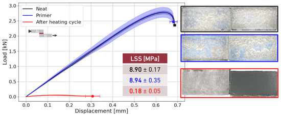
Figure 17.
Load–displacement curves and LSS of SLJ for 2K PU adhesive.
The joint strength measured after the heating cycle corresponds to the remaining strength, around 2% of the initial LSS, in which the specimens can be easily disassembled by hand. The reduction in strength indicates that the heating cycle is effective and can be reliably applied to other joints.
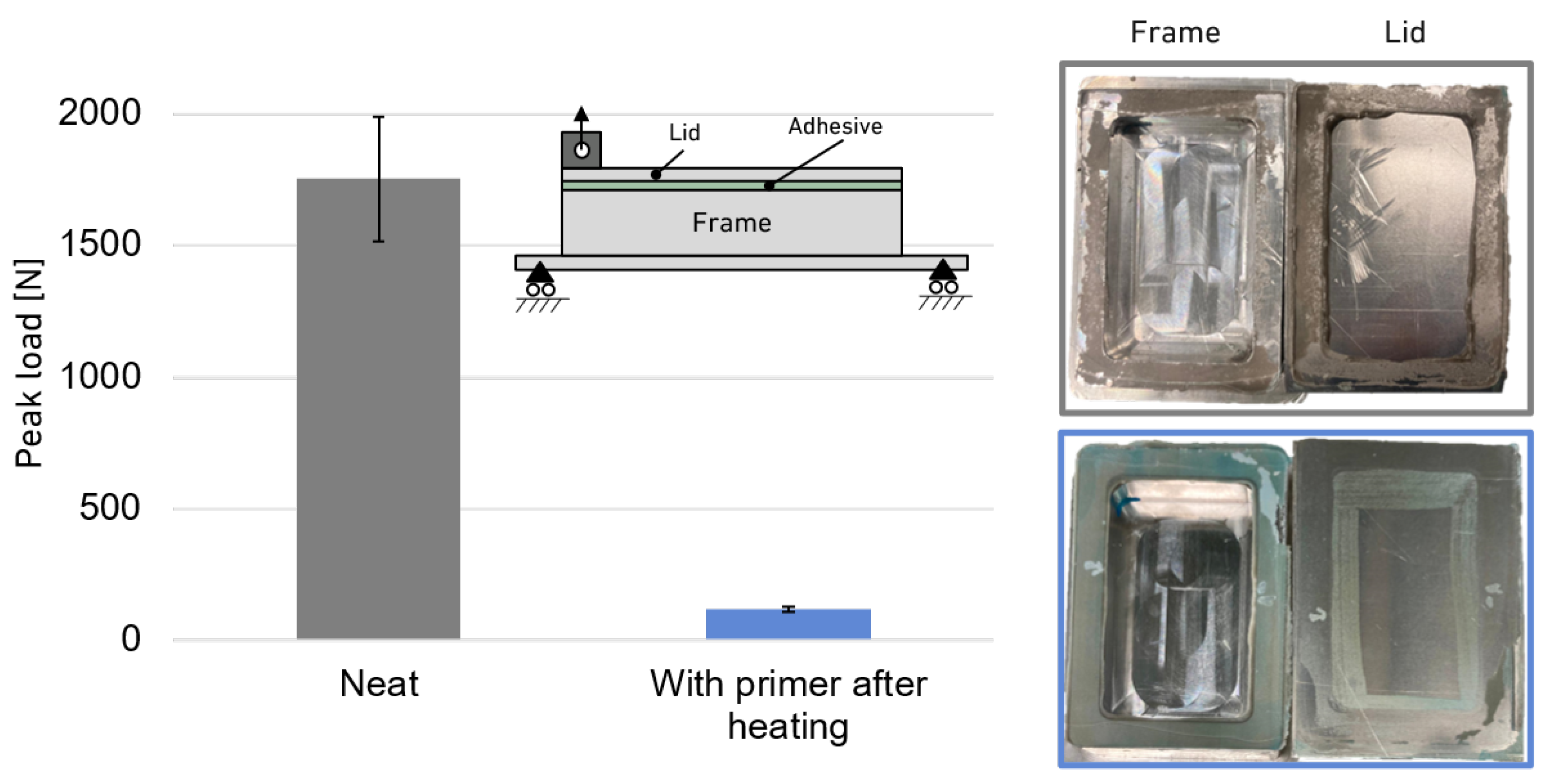
Regarding small-scale testing, Figure 18 presents the average peak loads from the pull-out tests conducted on specimens bonded with the neat and non-primed 2K PU adhesive after the heating cycle. The approximately tenfold reduction in peak load highlights the low residual mechanical force required to separate the two components. The debondable joint exhibited primarily adhesive failure at the interface between the primer and the top substrate, leaving only a small amount of primer residue that was easily removed with isopropyl alcohol (IPA). Because of the very thin adhesive layer, any remaining adhesive on the bottom substrate could be readily fractured and the surface cleaned, allowing the components to be rebonded without difficulty.
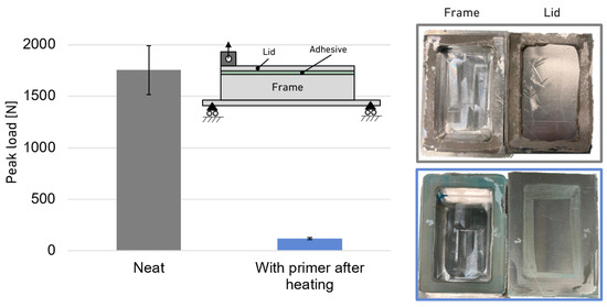
Figure 18.
Peak load of lid pull-out tests for neat and debondable primer with 2K PU adhesive.
4.3. Thermal Model
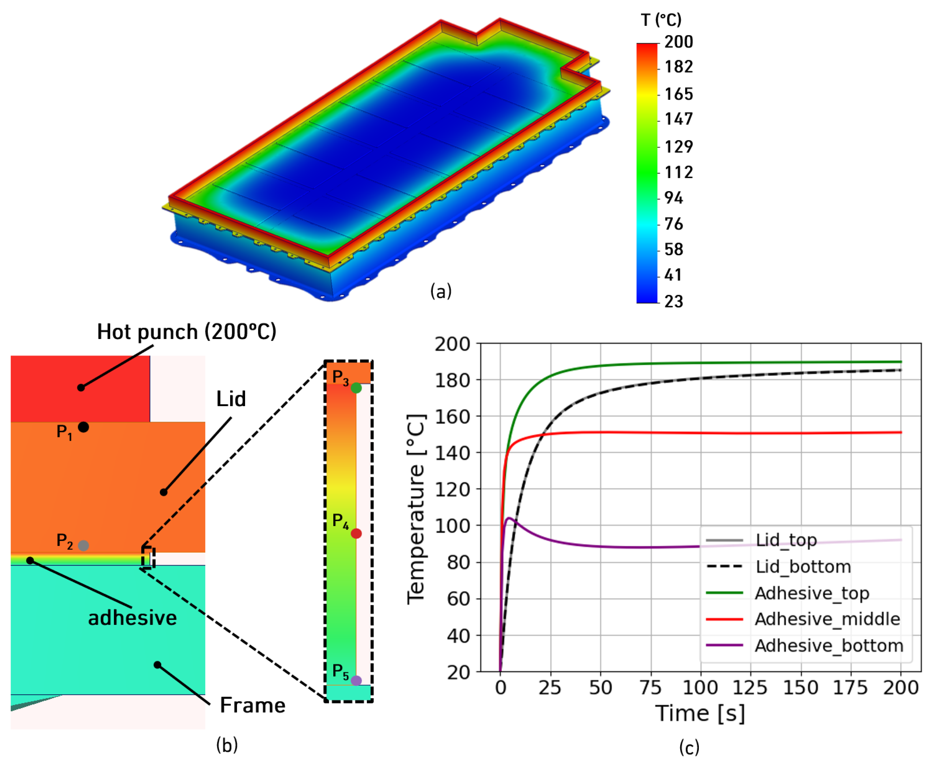
To better understand the heating location of the battery pack, five local points were selected to compute the temperature evolution for the simulation time. Two points, and , capture the top and bottom lid sections, while the other three capture the temperature evolution of the adhesive thickness, top (), middle () and bottom (), as illustrated in Figure 19, in which the battery pack heat map is shown at the end of the 200 s period. As observed, both the top and bottom parts of the lid have a very similar heating rate, converging to the hot punch temperature value. In addition, the adhesive layer reaches elevated temperatures more rapidly than the aluminium lid, even despite the hot punch being directly in contact with the top section of the lid. This can be explained by the different thermal time responses, which are significantly lower for the adhesive section, meaning that this part will respond very fast for the transient imposed heat transfer regime. The thermal time constant ( = , where is density, c the specific heat capacity, l the thickness and k thermal conductivity) of the adhesive layer is much shorter than that of the aluminium lid. Even though the conductivity of the adhesive is three orders of magnitude lower, the fact that the layer is almost negligible in thickness (0.3 mm) and therefore has a low thermal mass () makes the overall time constant much shorter. As a result, the material quickly reaches the activation energy of the primer (150 °C) on the surface () in approximately 20 s, while the aluminium alloy takes longer due to its higher heat capacity.
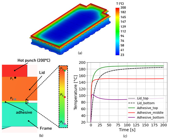
Figure 19.
Real-scale battery pack numerical results: (a) heat map; (b) probe point selection; (c) temperature evolution for selected points.
In any case, the adhesive-to-lid interface reaches the required primer triggering temperature rapidly, enabling the fast expansion of the TEPs. Nonetheless, it is essential to note that the other interface, adhesive to frame, does not reach a temperature level compatible with debonding. In fact, the recorded temperature values present a two-phase thermal evolution: during the initial heating, the adhesive close to the frame interface rises to 105 °C provided rapid heat wave propagation; after, once the steady state is reached, the interface temperature is governed by steady-state heat conduction through the adhesive layer, also considering the fact that the battery frame is at room temperature, serving as a heat sink. In order to also achieve the required temperature in the adhesive-to-frame interface, it is necessary to heat the bottom part of the joint or increase the punch temperature, tuneable properties that can be trivially altered according to the battery pack design.
5. Discussion
The mechanical characterisation of the lid sealant adhesive reveals properties that are well suited for EV battery pack applications which require both robust bonding and controlled debonding. The adhesive exhibits hyperelastic behaviour, typical of flexible polymers, with a low initial stiffness that transitions to a higher modulus under load, together with high ductility and toughness [41,42]. These properties contribute to damage tolerance and stable crack growth, which are crucial to maintaining a reliable seal under diverse loading and environmental conditions. Although alternative chemistries such as 1K and 2K PU formulations are also applicable, detailed information on specific commercial materials remains yet largely proprietary.
The heat-activated primer evaluated in this study demonstrates strong potential to enable the on-demand disassembly of bonded joints, an important requirement for repairable and recyclable EV battery pack designs. The primer showed excellent adhesion to both steel and aluminium substrates, as well as notable cohesive strength, resulting in comparable performance to epoxy and PU adhesive systems [43,44]. The MS adhesive exhibited a lower lap shear strength and a shift in failure mode to the primer–adhesive interface. MS polymers undergo a complicated curing process that involves hydrolysis, condensation and the formation of a network [45,46]. When this process commences, water attacks alkoxy silane groups (Si-OR), turning them into hydroxyl groups and sending minute particles floating away. The INDAR 150 primer, a polyamide-based matrix, relies on extremely strong bonds between its molecules for its mechanical strength but is famously susceptible to weak organic compounds [43,44,47]. When volatile substances from the MS adhesive seep into the primer during the assembly of the joint and the early stages of the curing process, they can soften the polyamide matrix, destroy the hydrogen bonds and cause the primer to expand, increasing internal stresses [43,47,48]. This chemically and mechanically altered surface then starts to lose its adhesion to the MS adhesive, causing the observed failure at the interface. While the intricate mechanisms and exact threshold values require further research, this mechanism can explain why MS adhesives do not behave like the tested epoxy and PU based adhesives. Coming back to the data, the excellent performance of the primer with the epoxy and PU systems provides hope that the heat-triggered debonding technique will be successful, and APPLUS+ RESCOLL has developed a new primer formula in which preliminary results show a higher resistance to volatile chemicals released during the curing of MS based adhesives.
As mentioned above, the primer performed consistently well with both epoxy and PU adhesives, demonstrating strong adhesion and stable mechanical performance under lap shear tests. These adhesives are widely used for structural bonding in vehicle assemblies, where joint durability and load transfer are critical. The fact that the primer maintains compatibility with such high-performance systems while still allowing for controlled heat-triggered debonding underscores its potential as an enabling technology for structural adhesive joints that can be easily disassembled when required.
Regarding the heating cycles for ease of disassembly, both convection- and conduction-based heating demonstrated the rapid and irreversible weakening of the primer, allowing the joints to be disassembled at room temperature with almost no residual strength. The small-scale pull-out tests further confirmed the drastic reduction in mechanical resistance after activation, leaving only minimal residue on the substrates. The heat map generation of the battery shows that the local heating application via conduction does not affect the overall temperature of the battery pack, even including the internal parts in which the convection of the internal trapped air is less important to produce a critical amount of heat to the cells of the battery. However, it is trivial that the primer activation strongly depends on the design of the battery lid material, in which the manufacturers have to consider such a point to easily access conduction heating in the debonding of the battery lid sealant. This clean separation, combined with the ease of re-cleaning the surfaces, supports repair, refurbishment and second-life applications, key priorities for sustainable EV battery pack design.
In general, this heat-triggered debonding primer has emerged as a promising solution for creating repairable and recyclable adhesive joints in EV battery systems. Its strong in-service performance, reliable debonding mechanism and straightforward post-processing make it a valuable contribution to more sustainable manufacturing and EoL strategies. Although the primer performs effectively with epoxy and PU adhesives, compatibility challenges with MS polymer systems remain an important limitation, but new formulations of the primer, with enhanced MS polymer compatibility, are now available and will be tested in future research work.
6. Conclusions
This study successfully characterised a hyperelastic MS lid sealant adhesive and evaluated a heat-triggered debondable primer for EV battery pack applications.
- Mechanical characterisation, including bulk tensile tests, TAST and DCB, revealed that the lid sealant adhesive possesses high ductility, 230% in tensile and 550% in shear strain, coupled with substantial tensile (3.1 MPa) and shear strength (2.6 MPa), typical values for 1K sealant adhesives, but also excellent fracture toughness, indicated by a critical energy release rate of approximately 4 N/mm, which contributes to significant damage tolerance and stable crack growth.
- The heat-triggered debondable primer, INDAR 150, was successfully activated at 150 °C for a few seconds, presenting a 98% reduction in lap shear joints strength, enabling easy disassembly with minimal residual force and requiring only manual effort.
- The primer demonstrates strong compatibility with epoxy and PU systems, without compromising the original joint strength and, in some cases, as for 1K PUs, even enhancing the LSS.
- Incompatibility with MS polymers results from curing byproducts that plasticise the polyamide matrix, highlighting the critical importance of considering adhesive curing chemistry when designing debondable systems.
- For a realistic EV battery pack, a transient thermal numerical model verifies that localised heating by conduction does not affect internal components since heating is localised around the bonded lid and the inner air pockets of the battery restrict heat transfer, thereby justifying thermal safety.
- Post-disassembly surfaces remain clean with minimal adhesive residue, requiring only wiping with IPA, enabling the efficient reuse of components for secondary bonding.
Although compatibility challenges with MS polymer adhesives remain for the moment, successful performance with epoxy and PU systems demonstrates the potential of this approach and future work to tailor primer formulations could further expand its applicability across diverse adhesive chemistries and applications in the automotive industry, especially for which heat induction is applicable to disassemble adhesively bonded parts. In addition, future research should focus on validation in a real-scale scenario, durability, scaling heat equipment for industrial repair facilities and also the amount of energy required to heat the lid-to-frame bonded area.
Author Contributions
Conceptualisation, M.M.K., E.A.S.M., R.J.C.C. and L.F.M.d.S.; resources, R.S. and M.O.; methodology, V.C.M.B.R.; investigation, V.C.M.B.R.; data curation, V.C.M.B.R.; writing—original draft preparation, V.C.M.B.R.; writing—review and editing, E.A.S.M., R.J.C.C., R.S., M.O. and L.F.M.d.S.; supervision, E.A.S.M., R.J.C.C. and L.F.M.d.S.; project administration, L.F.M.d.S. All authors have read and agreed to the published version of the manuscript.
Funding
This research was funded by the Project No. PTDC/EME-EME/2728/2021 through the Portuguese Foundation for Science and Technology (FCT).
Data Availability Statement
The original contributions presented in this study are included in the article. Further inquiries can be directed to the corresponding author.
Acknowledgments
The authors acknowledge Fundação para a Ciência e a Tecnologia (FCT) for its financial support to LAETA via the project UID/50022/2025 (DOI: https://doi.org/10.54499/UID/50022/2025).
Conflicts of Interest
Authors Robin Szymanski and Maxime Olive were emplyed by the company APPLUS+ RESCOLL. The remaining authors declare that the research was conducted in the absence of any commerical or financial relationship that could be contructed as a potential conflict of interest.
References
- Scott, S.; Islam, Z.; Allen, J.; Yingnakorn, T.; Alflakian, A.; Hathaway, J.; Rastegarpanah, A.; Harper, G.D.; Kendrick, E.; Anderson, P.A.; et al. Designing lithium-ion batteries for recycle: The role of adhesives. Next Energy 2023, 1, 100023. [Google Scholar] [CrossRef]
- Kırat, O.; Çiçek, A.; Yerlikaya, T. A New Artificial Intelligence-Based System for Optimal Electricity Arbitrage of a Second-Life Battery Station in Day-Ahead Markets. Appl. Sci. 2024, 14, 10032. [Google Scholar] [CrossRef]
- Warner, J. Lithium-Ion Battery Chemistries: A Primer; Elsevier Science: Amsterdam, The Netherlands, 2019. [Google Scholar]
- Cai, W. Lithium-ion Battery Manufacturing for Electric Vehicles: A Contemporary Overview. In Advances in Battery Manufacturing, Service, and Management Systems; Wiley: Hoboken, NJ, USA, 2017; pp. 1–28. [Google Scholar] [CrossRef]
- Dillard, D.A. Advances in Structural Adhesive Bonding; Elsevier: Amsterdam, The Netherlands, 2023. [Google Scholar]
- Grunder, S.; Lutz, A.; Koch, F.; Schmatloch, S. Adhesives for Battery Applications. Adhes. Adhes. Sealants. 2019, 16, 20–23. [Google Scholar] [CrossRef]
- Pistoia, G. Lithium-Ion Batteries: Advances and Applications; Elsevier Science: Amsterdam, The Netherlands, 2018. [Google Scholar]
- Rodrigues, V.C.; Kasaei, M.M.; Marques, E.A.; Carbas, R.J.; da Silva, L.F. Adhesive bonding in automotive battery pack manufacturing and dismantling: A review. Discov. Mech. Eng. 2025, 4, 25. [Google Scholar] [CrossRef]
- Rodrigues, V.C.M.B.; Marques, E.A.S.; Carbas, R.J.C.; Youngberg, M.; Dussaud, A.; Beygi, R.; Da Silva, L.F.M. Development and Study of a New Silane Based Polyurethane Hybrid Flexible Adhesive—Part 1: Mechanical Characterization. Materials 2023, 16, 7299. [Google Scholar] [CrossRef]
- Sampaio, R.F.; Zwicker, M.F.; Pragana, J.P.; Bragança, I.M.; Silva, C.M.; Nielsen, C.V.; Martins, P.A. Busbars for e-mobility: State-of-the-art review and a new joining by forming technology. In Mechanical and Industrial Engineering: Historical Aspects and Future Directions; Springer: Cham, Switzerland, 2021; pp. 111–141. [Google Scholar]
- Oehl, V. Adhesive and Sealing Systems for High-Voltage Batteries in Electric Vehicles. Adhes. Adhes. Sealants. 2019, 16, 16–19. [Google Scholar] [CrossRef]
- Beghi, M.; Braghin, F.; Roveda, L. Enhancing disassembly practices for electric vehicle battery packs: A narrative comprehensive review. Designs 2023, 7, 109. [Google Scholar] [CrossRef]
- Mulcahy, K.R.; Kilpatrick, A.F.R.; Harper, G.D.J.; Walton, A.; Abbott, A.P. Debondable adhesives and their use in recycling. Green Chem. 2022, 24, 36–61. [Google Scholar] [CrossRef]
- Bandl, C.; Kern, W.; Schlögl, S. Adhesives for “debonding-on-demand”: Triggered release mechanisms and typical applications. Int. J. Adhes. Adhes. 2020, 99, 102585. [Google Scholar] [CrossRef]
- Matsuo, K.; Inutsuka, M.; Ota, K.; Honda, T.; Ogawa, R.; Namihira, T.; Sasamoto, R.; Tokoro, C. Controlled pulsed discharge debonding of epoxy adhesives with conductive spots for enhanced recyclability. J. Adhes. 2025, 1–15. [Google Scholar] [CrossRef]
- Eppmann, M.; Rütters, M.; Szewieczek, A.; Viehöfer, M.A.; von Dungern, F.; Voß, M. Debonding of piezoelectric transducers for residue-free ultrasonic non-destructive testing. J. Adhes. 2025, 101, 837–870. [Google Scholar] [CrossRef]
- Kormpos, P.; Tserpes, K.; Berthe, L. Process simulation of laser shock-based disassembly of adhesively bonded composite/metallic structural parts: A numerical upscaling. J. Adhes. 2025, 101, 636–659. [Google Scholar] [CrossRef]
- Surós, M.; Verdugo, P.; Santiago, D.; De la Flor, S. Improving the reversible adhesion performance of an epoxy vitrimer adhesive through surface treatment technology. J. Adhes. 2025, 1–21. [Google Scholar] [CrossRef]
- Nishiyama, Y.; Uto, N.; Sato, C.; Sakurai, H. Dismantlement behavior and strength of dismantlable adhesive including thermally expansive particles. Int. J. Adhes. Adhes. 2003, 23, 377–382. [Google Scholar] [CrossRef]
- Morehouse, D.S., Jr.; Tetreault, R.J. Expandable Thermoplastic Polymer Particles Containing Volatile Fluid Foaming Agent and Method of Foaming the Same. U.S. Patent 3,615,972, 26 October 1971. [Google Scholar]
- Lee, B.; Son, I.; Kim, J.H.; Kim, C.; Yoo, J.Y.; Ahn, B.W.; Hwang, J.; Lee, J.; Lee, J.H. Polymeric nanocapsules containing methylcyclohexane for improving thermally induced debonding of thin adhesive films. J. Appl. Polym. Sci. 2018, 135, 46586. [Google Scholar] [CrossRef]
- Abenojar, J.; López de Armentia, S.; del Real, J.C.; Martínez, M.A. Influence of the Magnetization of Thermally Expandable Particles on the Thermal and Debonding Properties of Bonding Joints. Inorganics 2024, 12, 129. [Google Scholar] [CrossRef]
- Banea, M.; Da Silva, L.; Carbas, R. Debonding on command of adhesive joints for the automotive industry. Int. J. Adhes. Adhes. 2015, 59, 14–20. [Google Scholar] [CrossRef]
- Olive, M. Compositions Removable by Thermal Activation, Uses and Assemblies Comprising Such Compositions. U.S. Patent 2022/0289929-A1, 15 September 2022. [Google Scholar]
- NF T 76-142; Méthode de Préparation de Plaques D’adhésifs Structuraux Pour la Réalisation D’éprouvettes D’essai de Caractérisation. Afnor EDITIONS: La Plaine Saint-Denis, France, 1988.
- Carbas, R.J.C.; de Sousa Marques, E.A.; Akhavan-Safar, A.; Barbosa, A.S.Q.F.; da Silva, L.F.M. Adhesive Bonding Technology and Testing; John Wiley & Sons: Hoboken, NJ, USA, 2023. [Google Scholar]
- ISO 11003-2:2019(E); Adhesives—Determination of Shear Behaviour of Structural Bonds, Part 2: Thick-Adherend Tensile-Test Method. ISO: Geneva, Switzerland, 1993.
- ASTM D 3433-99; Standard Test Method for Fracture Strength in Cleavage of Adhesives in Bonded Metal Joints. ASTM International: West Conshohocken, PA, USA, 1999.
- ASTM D1002-10; Standard Test Method for Apparent Shear Strength of Single-Lap-Joint Adhesively Bonded Metal Specimens by Tension Loading. ASTM International: West Conshohocken, PA, USA, 2010.
- Anthony, J.; Paris, P.C. Instantaneous evaluation of J and C. Int. J. Fract. 1988, 38, R19–R21. [Google Scholar] [CrossRef]
- Ikeda, K.; Sekiguchi, Y.; Shimamoto, K.; Sato, C. Fracture energy determination of wedge-opening double cantilever beam tests. J. Adhes. 2025, 101, 1143–1162. [Google Scholar] [CrossRef]
- Kelham, S.; Rosenberg, H.M. The thermal conductivity and specific heat of epoxy-resin from 0.1–80K. J. Phys. C Solid State Phys. 1981, 14, 1737. [Google Scholar] [CrossRef]
- Nakamua, S.; Fujii, T.; Matsukawa, S.; Katagiri, M.; Fukuyama, H. Specific heat, thermal conductivity, and magnetic susceptibility of cyanate ester resins—An alternative to commonly used epoxy resins. Cryogenics 2018, 95, 76–81. [Google Scholar] [CrossRef]
- Li, J.; Tarvainen, T.; Rich, J.; Turunen, M.; Paulasto-Kröckel, M. Hyperelastic property measurements of heat-cured silicone adhesives by cyclic uniaxial tensile test. J. Electron. Mater. 2012, 41, 2613–2620. [Google Scholar] [CrossRef]
- Simon Portillo, F.J.; Cuadrado Sempere, Ó.; Marques, E.A.; Sánchez Lozano, M.; Da Silva, L.F. Mechanical Characterisation and Comparison of Hyperelastic Adhesives: Modelling and Experimental Validation. J. Appl. Comput. Mech. 2022, 8, 359–369. [Google Scholar]
- Roessing, M. Novel binders for sealants and adhesives, based on silane-modified polymers with lateral silane groups. PU Mag. 2012, 9, 248–250. [Google Scholar]
- Zhang, J.; Shen, H.Z.; Zhang, X.; Li, H.Y. Experimental and theoretical investigation of mechanical behavior related to temperature, humidity and strain rate on silane-modified polyurethane sealant. Polym. Test. 2021, 103, 107370. [Google Scholar] [CrossRef]
- Barbosa, N.; Campilho, R.; Silva, F.; Moreira, R. Comparison of different adhesively-bonded joint types for mechanical structures. Appl. Adhes. Sci. 2018, 6, 15. [Google Scholar] [CrossRef]
- de Castro Lopes, F.V.; Akhavan-Safar, A.; Carbas, R.J.; Marques, E.A.; Goyal, R.; Jennings, J.; da Silva, L.F. The interaction of loading mode and humidity on the properties degradation of an epoxy adhesive subjected to strength, fracture, and fatigue tests. J. Appl. Polym. Sci. 2023, 140, e53490. [Google Scholar] [CrossRef]
- Rahul, B.; Suresh, C.; Narendran, E.; Haribaskar, R. Mechanical characterization of adhesive in lap joint under tensile load. J. Polym. Compos. 2024, 11, 96–103. [Google Scholar]
- Brochier Salon, M.C.; Belgacem, M.N. Competition between hydrolysis and condensation reactions of trialkoxysilanes, as a function of the amount of water and the nature of the organic group. Colloids Surfaces A Physicochem. Eng. Asp. 2010, 366, 147–154. [Google Scholar] [CrossRef]
- Karna, N.; Joshi, G.M.; Mhaske, S. Structure-property relationship of silane-modified polyurethane: A review. Prog. Org. Coatings 2023, 176, 107377. [Google Scholar] [CrossRef]
- Idarraga-Mora, J.A.; Lemelin, M.A.; Weinman, S.T.; Husson, S.M. Effect of short-term contact with C1–C4 monohydric alcohols on the water permeance of MPD-TMC thin-film composite reverse osmosis membranes. Membranes 2019, 9, 92. [Google Scholar] [CrossRef] [PubMed]
- Rietzler, B.; Bechtold, T.; Pham, T. Controlled Surface Modification of Polyamide 6.6 Fibres Using CaCl2/H2O/EtOH Solutions. Polymers 2018, 10, 207. [Google Scholar] [CrossRef] [PubMed]
- Issa, A.A.; Luyt, A.S. Kinetics of alkoxysilanes and organoalkoxysilanes polymerization: A review. Polymers 2019, 11, 537. [Google Scholar] [CrossRef] [PubMed]
- Kumar, R.; Chavan, S. Numerical and Experimental Investigation of Thermal Behaviour for Fast Charging and Discharging of Various 18650 Lithium Batteries of Electric Vehicles. Int. J. Heat Technol. 2022, 40, 1492–1499. [Google Scholar] [CrossRef]
- Cervera-Moreno, J.; Martinez-Borquez, A.; Sotta, P.; Laurati, M. AFM investigation of the influence of ethanol absorption on the surface structure and elasticity of polyamides. SN Appl. Sci. 2019, 1, 1325. [Google Scholar] [CrossRef]
- Rönisch, R.; Beitmann, M. Method for Producing an Adhesive Based on a Silane-Modified Polymer and Adhesive Article, Such as an Adhesive Strip or a Label. WO 2017/162690 A1, 28 September 2017. [Google Scholar]
Disclaimer/Publisher’s Note: The statements, opinions and data contained in all publications are solely those of the individual author(s) and contributor(s) and not of MDPI and/or the editor(s). MDPI and/or the editor(s) disclaim responsibility for any injury to people or property resulting from any ideas, methods, instructions or products referred to in the content. |
© 2026 by the authors. Published by MDPI on behalf of the World Electric Vehicle Association. Licensee MDPI, Basel, Switzerland. This article is an open access article distributed under the terms and conditions of the Creative Commons Attribution (CC BY) license.