


Abstract
A control strategy combining the novel variable steering ratio (NVSR) and yaw moment control is proposed to address the stability issues in steer-by-wire (SBW) vehicles. The NVSR is designed based on variable yaw rate gains and incorporates a convolution smoothing algorithm. This ensures that the system meets the response requirements of SBW vehicles at low speeds, while satisfying their stability requirements at high-speeds. Secondly, precise control of the yaw torque is achieved by implementing the super-twisting sliding mode control (STSMC) algorithm. Finally, co-simulation experiments are carried out using Carsim–Simulink. These experiments demonstrate that the designed NVSR provides low-speed maneuverability and high-speed stability in vehicle steering, and that the PID effectively tracks the wheel steering angle. Additionally, the STSMC ensures the vehicle’s stability and safety.
1. Introduction
As vehicle intelligence continues to advance, researchers have become interested in cutting-edge technologies, one of which is steer-by-wire (SBW). Unlike the mechanical steering system, SBW uses information transmitted by sensors, electronic control units (ECUs) and other components to control the wheel steering angle. Additionally, it saves cockpit space and ensures driver safety [1,2].
A fixed steering ratio limits improvements to vehicle maneuverability and safety; the emergence of variable steering ratio (VSR) in the SBW system overcomes this limitation. To improve the steering performance of SBW vehicles, Wen et al. [3] proposed a design method for the VSR. At low and medium speeds, the VSR is designed based on a constant yaw rate gain, while at high speeds, fuzzy control is applied to the steering ratio to accommodate the driver’s preferences. Simulation results showed that the system provides good steering responsiveness at low speeds, while ensuring steering safety at high speeds. Huang et al. [4] designed a VSR by combining the yaw rate gain with the lateral acceleration gain, and optimized it using a fuzzy neural network. Finally, through experiments, they found that the proposed method effectively ensured both low-speed maneuverability and high-speed stability in forklift steering. Liu et al. [5] used a particle swarm optimization (PSO) algorithm to obtain the optimal yaw rate gain based on comprehensive stability evaluation metrics. They then designed a VSR based on the gain, and finally conducted hardware-in-the-loop (HIL) experiments to validate the superiority of the VSR.
In the field of vehicle stability control, Zhang et al. [6] proposed an adaptive linear quadratic regulator (LQR) feedback controller based on a piecewise affine tire model. This controller ensured that the vehicle maintains a low yaw rate tracking error under various operating conditions by adjusting the adaptive weighting coefficients. However, sudden changes in path curvature can significantly affect the performance of the adaptive LQR. Zou et al. [7] based the design of the yaw rate controller on hybrid H2–H∞ robust control theory, combining it with a cross-coupled control structure and SMC algorithm to improve the synchronization performance of the dual motor and ensure stable vehicle driving. Gong et al. [8] designed a stabilized H∞ controller to control the vehicle sideslip angle and yaw rate while tracking the target front-wheel steering angle. They used an event-triggered adaptive fault-tolerant controller (ET-AFTC) to drive the entire SBW system, enhancing its robustness and reducing the number of communication resources required. H∞ control can improve vehicle stability, but it cannot effectively mitigate the adverse effects caused by the system’s dynamic performance. Bai et al. [9] integrated acceleration slip regulation (ASR), brake force distribution and yaw torque control systems, accurately calculating and distributing the required torques for each wheel based on MPC. The proposed integrated controller was found to significantly improve vehicle stability during simulation experiments. It is proposed that a lateral stability control strategy for four-wheel independent vehicles uses an SMC algorithm to reasonably calculate and distribute the desired additional yaw torque [10,11]. However, vibration is inevitable in the high-frequency switching state near the sliding mode surface. Teng et al. [12] proposed a coordinated control strategy based on robust deep reinforcement learning. Using linear matrix inequalities, they designed active rear-wheel steering (ARS) and direct yaw control (DYC) and proposed a deep deterministic policy gradient algorithm to train the system. Real vehicle experiments revealed that the designed control algorithm significantly improved vehicle stability. In order to address the impact of external disturbances and transient errors on vehicle stability, Krishna et al. [13] proposed a steering controller based on an adaptive neural-fuzzy inference system. Within the framework of an adaptive neural network, a fuzzy inference system is trained to enable adaptive learning of the mapping rules between system input and output signals. Subsequently, the wheel steering angles were adjusted as necessary based on the yaw rate error data, effectively ensuring the vehicle’s stability during operation. To improve vehicle stability, Lenzo et al. [14] proposed a stability control method based on a single-input single-output (SISO) yaw rate controller. This method achieved continuous active control of both the sideslip angle and yaw rate by adjusting the reference yaw rate according to the actual sideslip angle. The stability of the system was effectively proven using Lyapunov functions. Phase-plane analysis and simulation experiments fully demonstrated the SISO yaw rate controller’s effectiveness in enhancing vehicle stability. Ahmadian et al. [15] proposed a model reference adaptive control strategy for multi-input multi-output (MIMO) systems. They employed active front steering (AFS) and DYC to generate an additional wheel steering angle and corrected yaw torque. At the same time, a nonlinear term was incorporated into the adaptive control law to account for parameter uncertainties and disturbances. The simulation results showed that the proposed control strategy tracked the target yaw rate and significantly reduced the vehicle sideslip angle.
For SBW vehicles, fault diagnosis technology is essential. Melendez-Useros et al. [16] combined a robust switching Luenberger observer and an unknown-input observer to estimate the state of the vehicle and faults in the actuators. They also constructed a long short-term memory neural network (LSTM) to detect sensor faults to prevent erroneous estimates of actuator faults. Finally, this fault diagnosis strategy was effectively validated by conducting HIL experiments.
Based on the literature reviewed above, there is still room for improvement in the stability control of vehicles. The contributions of this paper are summarized below. A design for the novel VSR (NVSR) is presented. The NVSR is designed by applying different yaw rate gains for low speed and high speed, and is smoothed using a convolution smoothing algorithm. This ensures light steering at low speeds, stability at high speeds, and prevents abrupt changes in the gear ratio. Then, a PID is used to adjust the tracking error in the wheel steering angle, making sure that the vehicle steers in accordance with the driver’s intention. Finally, the super-twisting sliding mode control (STSMC) algorithm is utilized to design the yaw torque controller, thereby achieving vehicle stability control.
2. System Model
2.1. Vehicle Dynamics Model
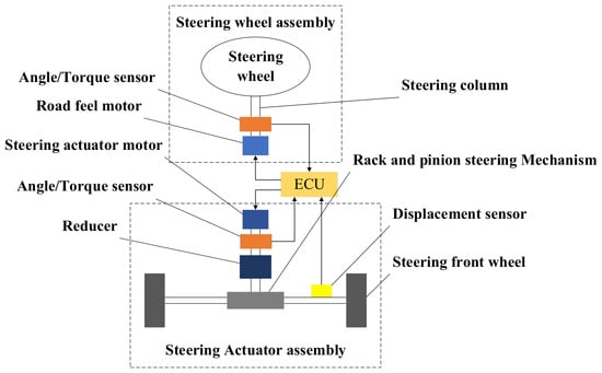
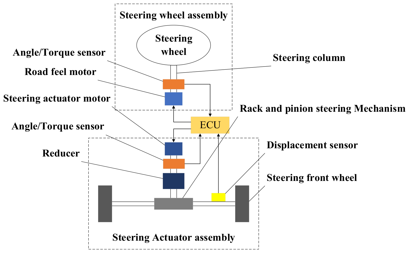
The structure of the SBW system is shown in Figure 1. It consists primarily of a steering wheel assembly, an ECU and a steering actuation assembly [17]. The steering wheel assembly comprises the steering wheel, steering column and road feel motors. The steering actuation assembly mainly comprises the steering motor, reducer, rack-and-pinion steering mechanism and wheel. The ECU receives various sensor signals and performs relevant calculations to control the operation of the road feel motor and steering motor, enabling the vehicle to perform steering movement.
Figure 1.
The structure of steer-by-wire (SBW) system.
The kinematic model of the steering actuator assembly during vehicle operation is as follows:
where Je is the steering actuator motor’s torque of inertia; Be is the steering actuator motor’s damping coefficient; ge is the reducer’s reduction ratio; δe is the steering actuator motor’s steering angle; Te is the steering actuator motor’s electromagnetic torque; Tp is the equivalent steering resistance torque on the steering gear pinion; Ke is the steering motor shaft’s torsional stiffness; xr is the rack displacement; and rp is the pinion pitch circle’s radius.
According to Kirchhoff’s law, the voltage and electromagnetic torque of the steering motor can be obtained as follows:
where Ua is the steering motor’s voltage; Ra is the steering motor’s resistance; La is the steering motor’s inductance; Ia is the steering motor’s current; Kf is the steering motor’s back electromotive force coefficient; and Kt is the steering motor’s electromagnetic torque coefficient.
The dynamic model of the rack-and-pinion steering mechanism is as follows:
where M is the mass of the rack and pinion; Br is the damping coefficient of the rack and pinion; Tfl and Tfr are the self-aligning torque of the left and right front wheels; and lfl and lfr are the lengths of the left and right front-wheel steering arms.
2.2. 2-Degree-of-Freedom Model
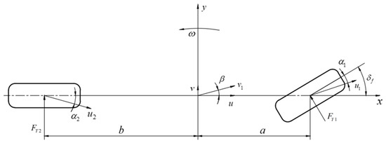
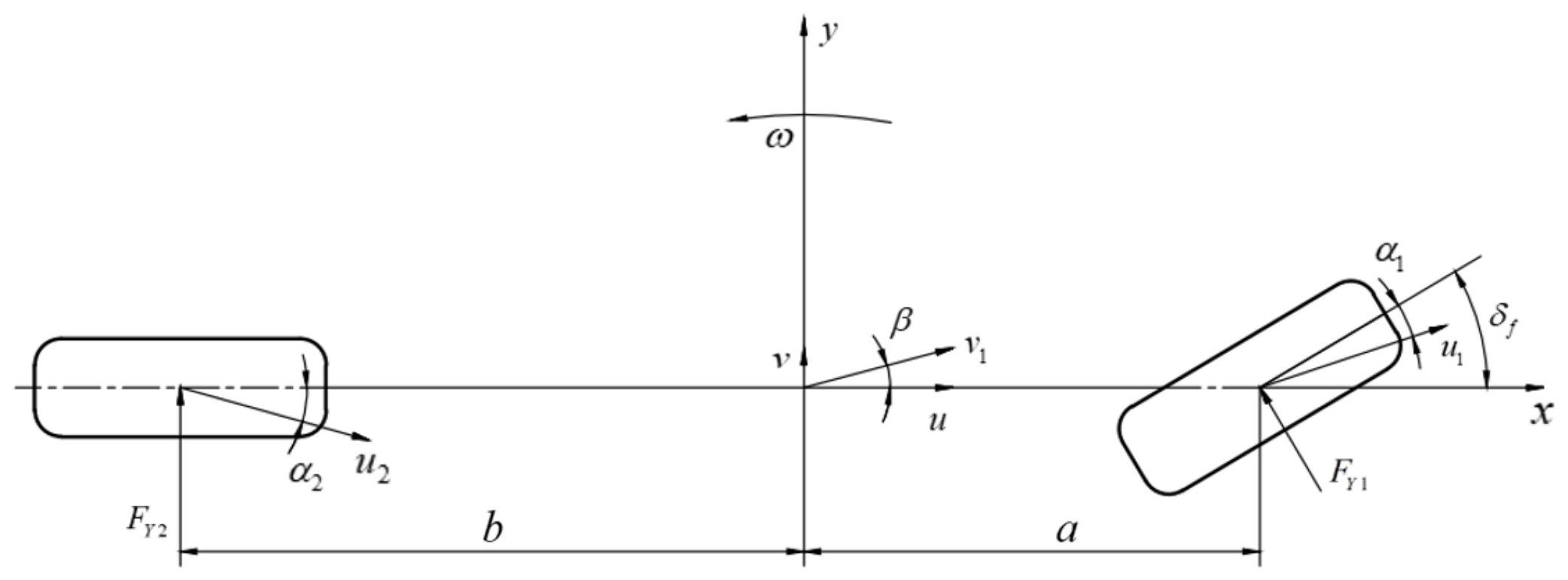
The vehicle is a complex system. For simplicity, a 2-degree-of-freedom (2DOF) linear dynamic model [18] is constructed here, as shown in Figure 2. The following assumptions are made in this model:
Figure 2.
Two-degree-of-freedom (2DOF) dynamic model.
Assumption 1.
The vehicle’s longitudinal velocity remains constant;
Assumption 2.
The tire’s sideslip characteristics are within the linear range;
Assumption 3.
Ignore the changes in tire characteristics caused by variations in left and right wheel loads, as well as the effect of the tire’s self-aligning torque.
Despite the simplifications described above, this model can still effectively characterize the vehicle’s yaw stability.
Applying Newton’s second law to perform a force analysis on Figure 2 yields the following.
where FY1 and FY2 represent the lateral reaction forces exerted by the ground on the front and posterior wheels; δf denotes the steering angle of the front wheels; a and b denote the distances from the vehicle’s center of mass to the front and posterior axles; m represents the total vehicle mass; ay denotes the lateral acceleration; Iz is the vehicle’s moment of inertia about the z-axis; and γ is the yaw rate.
Within the linear region, the front-wheel steering angle is small and cos δf = 1. The lateral force is linearly related to the sideslip angle of the wheel, so the following can be derived:
The formula for the vehicle’s lateral acceleration can be expressed as follows:
The sideslip angles of the wheels are as follows:
where k1 and k2 represent the lateral stiffness of the front and posterior axles; α1 and α2 denote the sideslip angles of the front and posterior wheels; β indicates the vehicle sideslip angle; u is the fraction of the vehicle’s centroid velocity along the x-axis; and v is the fraction of the vehicle’s centroid velocity along the y-axis.
By combining Equations (6)–(12), we obtain the following equations:
Rewriting Equations (13) and (14) as a state equation gives the following:
where X = [β, γ]T, U = δf, A = [a11, a12; a21, a22], a11 = (k1 + k2)/(mvx), a12 = (ak1 − bk2)/(mvx2) − 1, a21 = (ak1 − bk2)/Iz, a22 = (a2k1 + b2k2)/(Izvx), B = [−k1/(mvx), −ak1/Iz]T.
3. Angle Tracking Control Strategy
3.1. Variable Steering Ratio Design
The SBW system transmits steering wheel angle information to the controller in the form of electrical signals. The controller then uses a VSR strategy to calculate the wheel steering angle, controlling the operation of the steering actuator assembly and steering the vehicle. Therefore, the steering ratio can be expressed as follows:
where δsw represents the steering wheel angle; i represents the steering ratio.
To ensure good steering precision and stable yaw response, the VSR is designed based on a constant yaw rate gain. The relationship between the vehicle’s yaw rate and the front-wheel steering angle can be expressed based on Equation (15) as follows:
where γr indicates the steady-state yaw rate; vx signifies the longitudinal speed; and K signifies the stability factor.
According to Equations (16)–(18), the steering ratio can be expressed as follows:
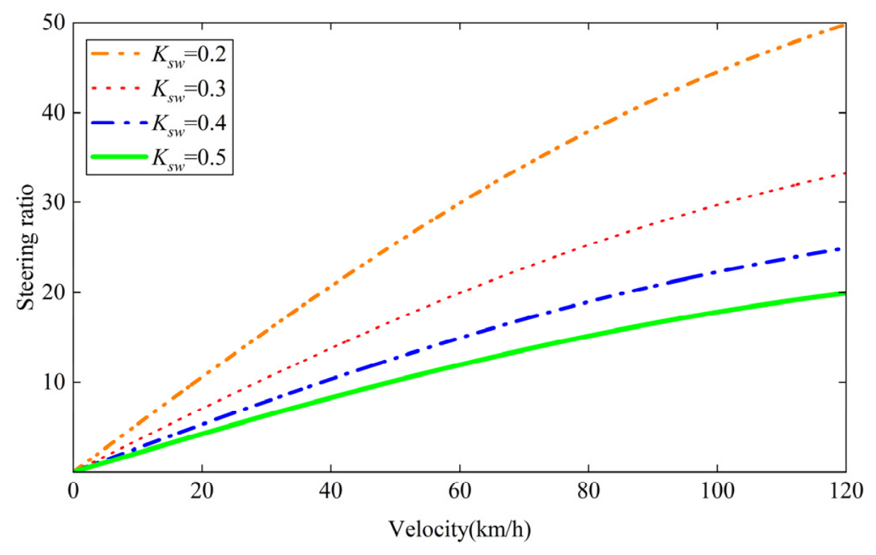
where Ksw = γr/δsw represents the steady-state yaw rate gain; according to [19], this typically ranges from 0.2 s−1 to 0.5 s−1.
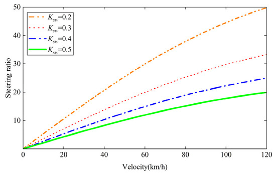
Figure 3 shows the VSR curve under different yaw rate gains.
Figure 3.
The curve of the steering ratio under different Ksw.
According to Figure 3, after considering the requirements for low-speed agility and high-speed stability in vehicle steering, Ksw1 is set to 0.5 s−1 at lower speeds, while Ksw2 is set to 0.4 s−1 at higher speeds. In this case, the VSR can be expressed as follows:
where vx = 80 km/h represents the speed when the yaw rate gain changes; iv is the VSR that changes with vehicle speed.
When driving at low speeds, an excessively low steering ratio causes the wheels to reach their maximum steering angle at a small steering wheel angle. This increases the load on the steering motor. Conversely, when driving at high speeds, an excessively high steering ratio can lead to a sluggish steering response, thereby increasing the risk of accidents [20]. Taking these factors into account, the VSR can be designed as follows:
where v1 is the vehicle speed at which the steering ratio begins to change as the vehicle speed increases; v3 is the vehicle speed at which the steering ratio reaches its maximum value as the vehicle speed increases.
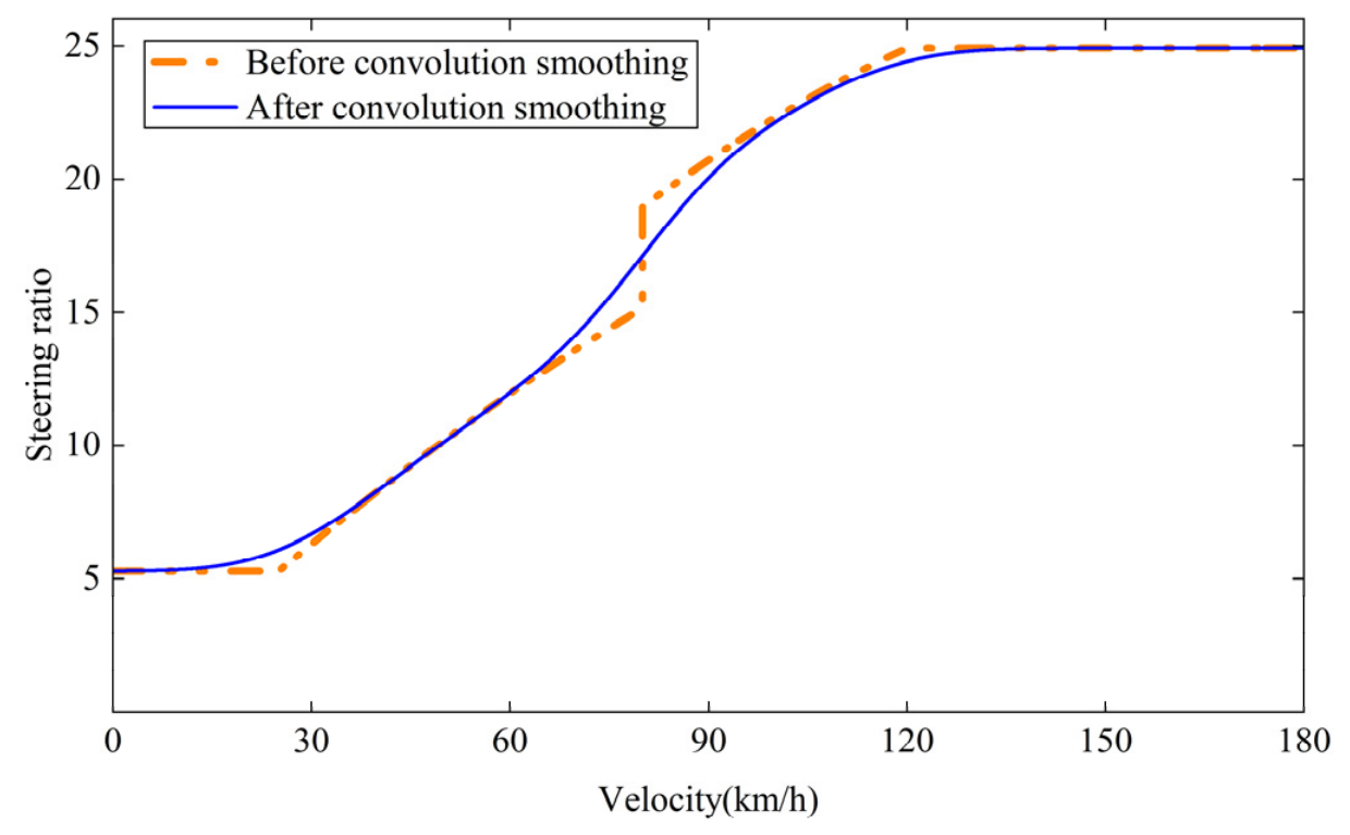
Based on Equation (21), as speed increases, the steering ratio undergoes a sudden change at v2. Furthermore, the VSR curve is not smooth at speeds v1 and v3. Both situations can lead to abrupt changes in steering behavior during acceleration and deceleration, which affect the vehicle’s stability. Therefore, a convolution smoothing algorithm is introduced [21,22].
To facilitate convolution smoothing of the steering ratio, Equation (21) is discretized as follows:
where j = 1, 2, …, 2N + 1; Δvx = 0.01 km/h is the sampling step size.
To implement Gaussian smoothing, the discrete Gaussian kernel function g(l) is defined as follows:
where the standard deviation σ = 10, and the independent variable tk = k·Δvx; k = −N, −N + 1, …, N; l = 1, 2, …, 2N + 1.
To maintain the overall average level of the inputs, Equation (24) is normalized as follows:
where is the normalized discrete Gaussian kernel function.
Convolution operations exhibit boundary effects, so the VSR iv is symmetrically padded, resulting in the following VSR after padding:
where o = N + 1, N, …, 2; n = N + 1, N + 2, …, 2N; ivp is the VSR after padding.
Smoothing of the filled VSR ivp can be achieved through the following discrete convolution:
where ivps is the VSR obtained after applying convolution smoothing to ivp; w = 1, 2, …, 6N + 1; k = max {1, w − 2N + 1}, max {1, w − 2N + 1} + 1, …, min {w, 4N + 1}.
To ensure that the signal length remains unchanged, the padding portion of ivps is now removed, resulting in the following equation:
where ivs is the novel variable steering ratio.
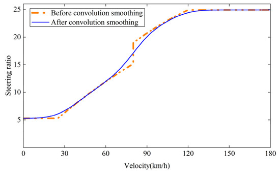
Figure 4 shows the VSR curves before and after convolution smoothing.
Figure 4.
The curve of the variable steering ratio (VSR) before and after convolution smoothing.
As shown in Figure 4, the convolution smoothing algorithm resolves the issue of sudden changes in the steering ratio.
3.2. PID Controller
To mitigate inconvenience to the driver caused by tracking errors, a PID algorithm is used to regulate the steering motor voltage.
The PID algorithm is expressed as follows:
where e(t) = δsw/ivs − δf represents the wheel angle error; Kp, Ki and Kd represent the proportional, integral and derivative gains; t represents the system’s run time; and u(t) is the steering motor voltage.
4. Stability Control Strategy
A yaw moment control strategy based on STSMC is proposed for tracking the ideal vehicle sideslip angle and yaw rate. The vehicle sideslip angle reflects the degree of deviation between the vehicle’s actual heading and its longitudinal axis. Under ideal steering conditions, the vehicle’s heading should align with its direction of travel. Therefore, the ideal vehicle sideslip angle is 0. In a steady state, the rate of change in the vehicle sideslip angle, dβ/dt, is zero, as is the yaw acceleration, dγ/dt. Therefore, based on Equation (15), the ideal yaw rate can be derived as follows:
During steady-state steering, the vehicle’s lateral acceleration is as follows:
The maximum lateral acceleration that the road surface can provide is approximately μg. From this, the following can be derived:
where μ is the road surface coefficient of friction, and g is the acceleration due to gravity.
Based on Equations (30) and (32), the following can be derived:
Figure 5 shows the yaw torque control strategy.
Figure 5.
Yaw torque control strategy.
Introducing an additional yaw torque into Equation (15) yields the vehicle’s target state equation:
where ΔT is the additional yaw torque.
The STSMC’s function is to regulate the vehicle sideslip angle and yaw rate to ensure driving stability. According to the literature [23], the sliding mode dynamic equations in this algorithm can be expressed as follows:
where s is the sliding surface function; n1 and n2 are undetermined coefficients.
To flexibly adjust the convergence rate of errors, the following linear sliding surface is adopted:
where c1 > 0, c2 > 0; e is error.
Therefore, the following sliding mode surfaces are designed for the vehicle sideslip angle and yaw rate.
where c1 > 0, c2 > 0; e is the error; sβ and sγ are the sliding surface functions of the vehicle sideslip angle and yaw rate, respectively; eβ is the error between the theoretical and actual vehicle sideslip angle; eγ is the error between the theoretical and actual yaw rate; and c1β, c2β, c1γ and c2γ are positive factors.
The following convergence law function may be adopted based on Equations (36)–(38):
where n1β >0 and n1γ >0; the values of n2β and n2γ are determined by the following equations:
where pβ > 0 and pγ > 0, and hβ and hγ are the switching boundaries.
Equations (34), (37) and (38) are used to obtain the following:
where ΔTβ and ΔTγ are the additional yaw torques derived from the vehicle sideslip angle sliding surface and yaw rate sliding surface; ξ = a11eβ + a12eγ and λ = a21eβ + a22eγ.
Taking both the sideslip angle and yaw rate into account, the total additional yaw torque can be expressed as follows:
where τ is the weighting coefficient; ΔT is the total additional yaw torque.
The additional yaw torque can be generated by applying braking torque to the posterior wheels of the vehicle:
where r is the tire rolling radius; B2 is the posterior wheel track width; and Tb is the braking torque.
The following Lyapunov function is constructed for the purpose of verifying the stability of the controller:
where zβ = n2βsign(sβ) dt, zγ = n2γsign(sγ) dt.
The following equation can be derived by using Equations (39), (40) and (47):
where ε1, ε2, ε3 and ε4 are positive, 1/ε1 + ε2 ≤ 1/n2β, 1/ε3 + ε4 ≤ 1/n2γ, and α = min {n1β/2, n1γ/2} > 0; C is a constant that can be overwhelmed by negative terms when the system is far from the equilibrium point.
According to Equation (48), it is a negative semi-definite function. When dV/dt = 0, sβ = 0 and sγ = 0. Based on the Lassalle invariance principle, the control system will tend to stabilize.
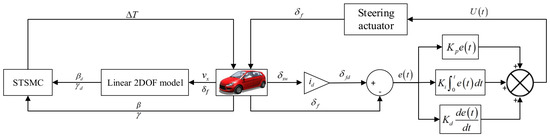
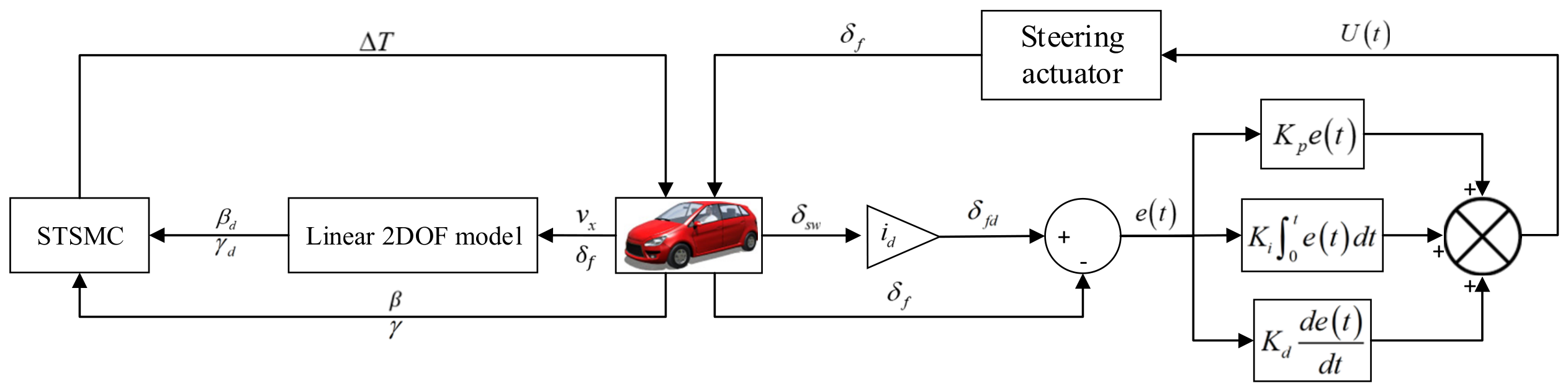
Figure 6 shows the complete block diagram of the control strategy proposed in this paper. The control architecture is primarily divided into two levels: the upper level calculates the desired front-wheel steering angle based on the steering wheel angle and the NVSR. It then provides the error between this value and the actual front-wheel steering angle as input to the PID, which uses this information to determine the steering motor voltage. This achieves tracking control of the wheel steering angle. The lower-level employs STSMC to generate an additional yaw torque, thereby ensuring the vehicle’s driving stability.
Figure 6.
Block diagram of the system as a whole.
5. Simulation Experiments
A Carsim-MATLAB/Simulink co-simulation platform was set up based on Carsim 2020.0 and MATLAB R2022a, and a series of experiments was conducted to verify the effectiveness of the steering angle tracking control and STSMC proposed in this paper. A Class B vehicle was selected for testing on a dry and level road surface with a road adhesion coefficient of 0.85. Table 1 presents the vehicle’s key parameters.
Table 1.
Vehicle specifications.
5.1. Verification of Variable Steering Ratio
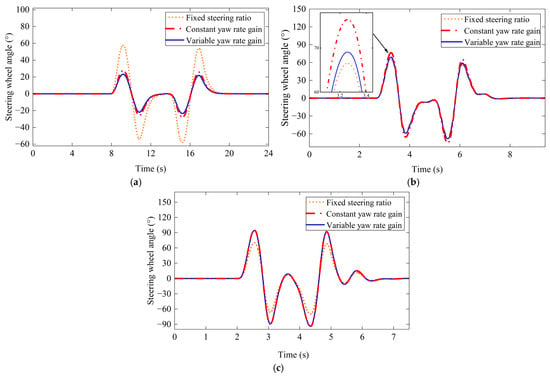
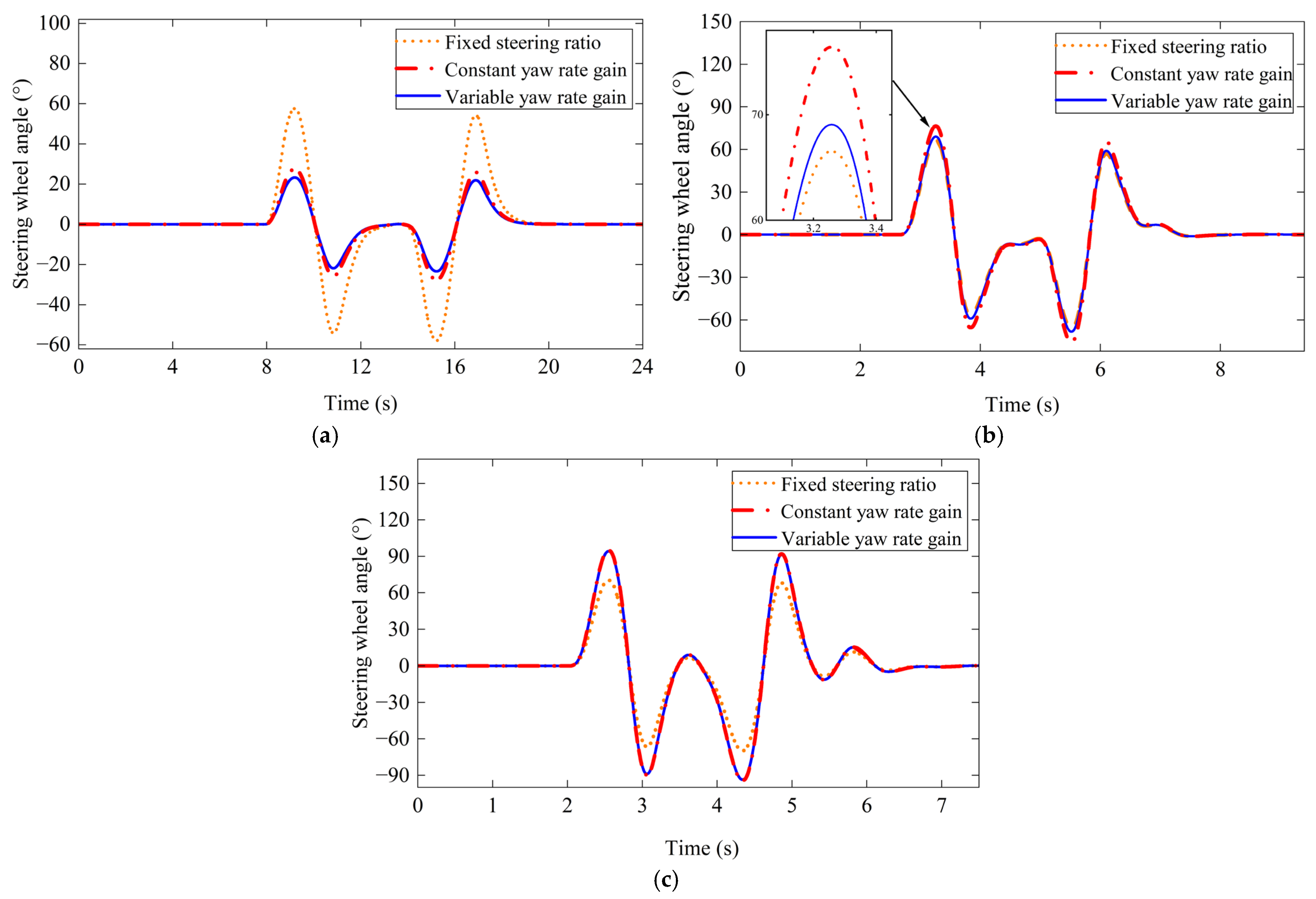
To verify the effectiveness of the NVSR, a double-lane-changing experiment was conducted. The steering wheel angles required to achieve the same wheel steering angle were measured for vehicles using different steering ratio control strategies. The results are shown in Figure 7.
Figure 7.
The curve showing the change in steering wheel angle at different vehicle speeds: (a) 30 km/h, (b) 80 km/h, (c) 100 km/h.
Figure 7a shows that when driving at low speeds, the NVSR allows the vehicle to complete a predetermined steering maneuver with a smaller steering wheel angle than the other two steering ratios. This alleviates the driver’s steering burden. Figure 7b shows that at medium speeds, the NVSR brings the steering wheel angle closer to that of vehicles with a fixed steering ratio. This fully considers the driving habits of drivers of conventional vehicles. Figure 7c shows that, at high speeds, vehicles equipped with an NVSR require a larger steering wheel angle than conventional vehicles. This enhances driving stability.
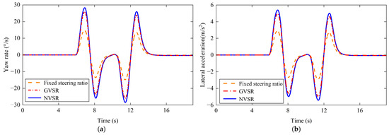
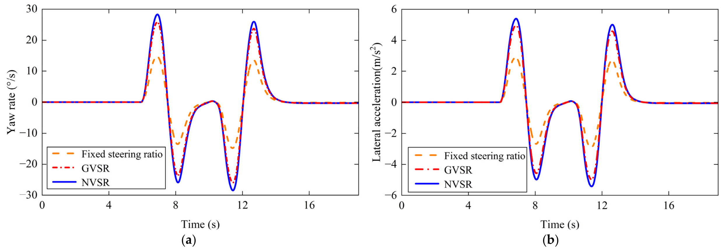
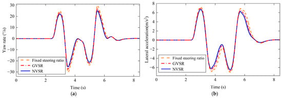
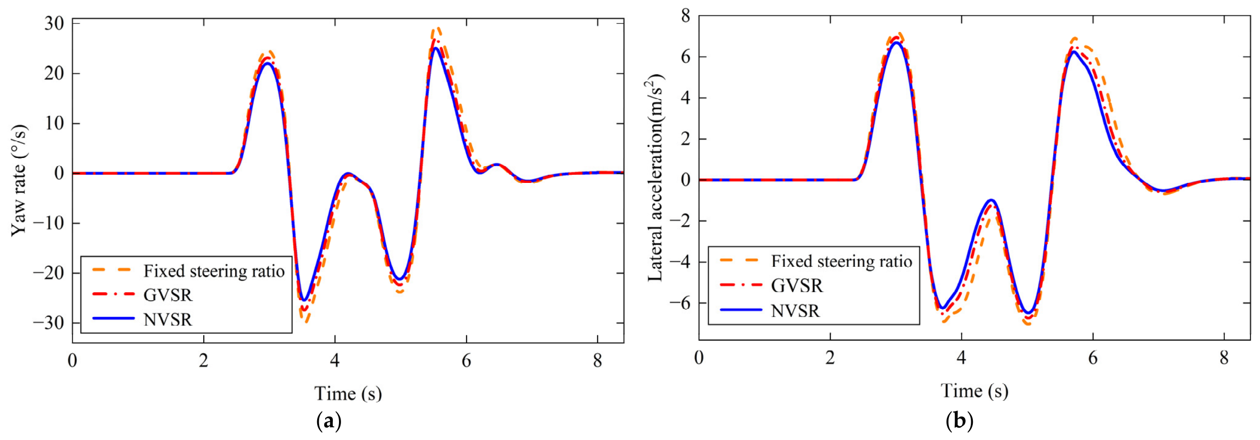
To more clearly demonstrate the superiority of the NVSR, the vehicle’s yaw rate and lateral acceleration were measured at the same steering wheel angle. The results of these measurements are shown in Figure 8 and Figure 9. The GVSR represents the VSR that is designed based on a constant yaw rate gain.
Figure 8.
Simulation results at 40 km/h: (a) yaw rate; (b) lateral acceleration.
Figure 9.
Simulation results at 90 km/h: (a) yaw rate; (b) lateral acceleration.
As shown in Figure 8, the NVSR system provides the vehicle with a higher yaw rate and lateral acceleration at low speeds, thereby improving maneuverability during low-speed steering.
As can be seen in Figure 9, vehicles fitted with the NVSR system demonstrate reduced yaw rate and lateral acceleration during high-speed driving. This improves the vehicle’s steering stability.
5.2. Verification of Angle Tracking
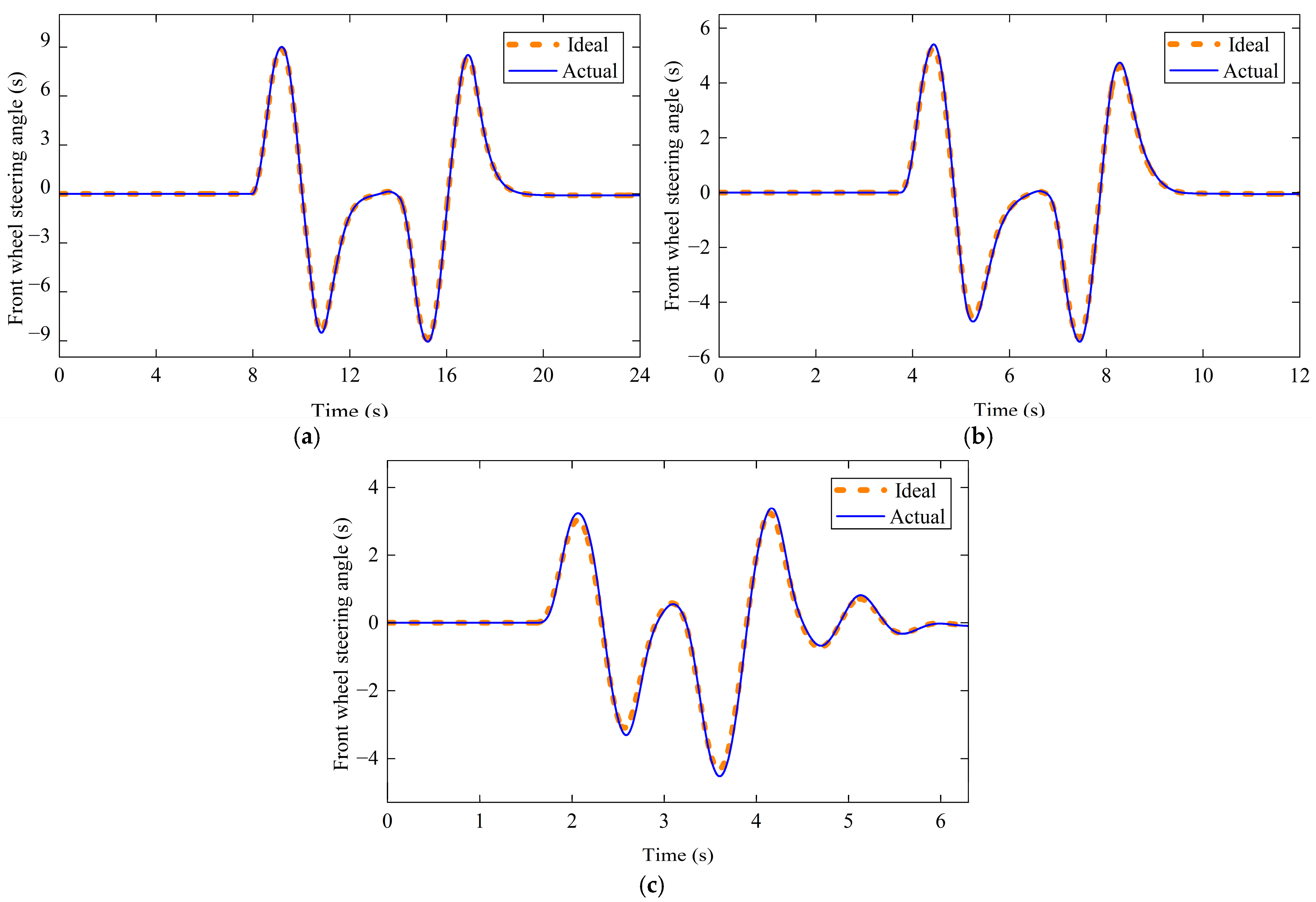
To ensure that the actual front-wheel steering angle of the vehicle tracks the ideal steering angle derived from the NVSR in real time, the double-lane-changing experiment is conducted. Figure 10 shows the results of wheel steering angle tracking control using a PID.
Figure 10.
The angle tracking performance curves of the PID at different vehicle speeds: (a) 30 km/h, (b) 60 km/h, (c) 120 km/h.
Figure 10 shows that the PID can effectively track the front-wheel steering angle, with better tracking performance at lower speeds.
Table 2 shows the maximum steering angle tracking deviation of the PID.
Table 2.
The maximum angle tracking deviation.
According to Table 2, the maximum steering angle tracking deviations under PID are 1.63%, 2.74% and 4.71% at the three speeds. Therefore, the PID ensures good steering angle tracking accuracy.
5.3. Verification of Stability
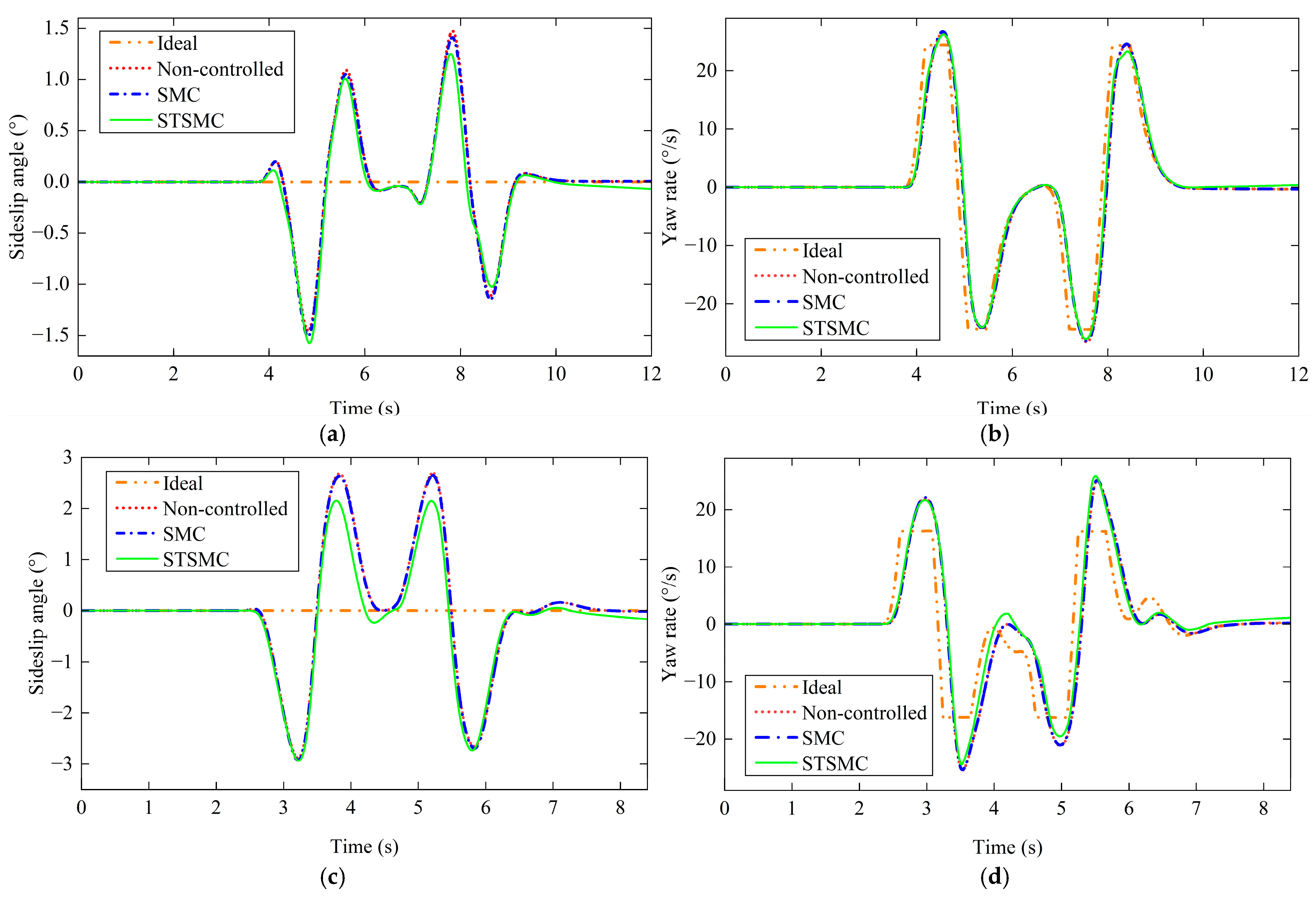
The vehicle exhibits high stability at lower speeds; therefore, the control performance of the stability controller when operating at low speeds will not be discussed here. Table 3 shows the relevant parameters of the STSMC used in the simulation experiments. Figure 11 presents the vehicle’s status at different speeds.
Table 3.
The relevant parameters of the STSMC in the simulation experiments.
Figure 11.
The vehicle’s status at different speeds: (a) curve of the change in the vehicle sideslip angle at 60 km/h; (b) curve of the change in yaw rate at 60 km/h; (c) curve of the change in the vehicle sideslip angle at 90 km/h; (d) curve of the change in yaw rate at 90 km/h.
As Figure 11 shows, using the STSMC algorithm to control the additional yaw torque enables better tracking of the ideal vehicle sideslip angle and yaw rate. Furthermore, STSMC reduces the response time and improves vehicle stability during high-speed driving compared to SMC.
Table 4 shows the performance index for vehicle sideslip angle.
Table 4.
Comparison of sideslip angle control performance index.
According to Table 4, the maximum deviation in vehicle sideslip angle for the STSMC is 2.1507°, which is lower than that of the other two control methods.
Table 5 shows a comparison of the maximum yaw rate error and the maximum root mean square (RMS) at 60 km/h. Table 6 shows a comparison of the maximum yaw rate error and the maximum RMS at 90 km/h. eγmax is the maximum yaw rate error; RMSβ is the root mean square value of the sideslip angle; and RMSγ is the root mean square value of the yaw rate.
Table 5.
Comparison of maximum error and maximum root mean square (RMS) at 60 km/h.
Table 6.
Comparison of maximum error and maximum RMS at 90 km/h.
According to Table 5, the eγmax, RMSβ and RMSγ values of STSMC are 1.8247°/s, 0.007602° and 0.1816°, respectively, which are all smaller than those of other control methods.
According to Table 6, the STSMC’s eγmax reaches 9.6281°/s. However, this value reflects only the vehicle’s instantaneous state and does not reflect its overall tracking performance. By contrast, the relatively small RMSβ and RMSγ of the STSMC indicate its superior overall tracking performance.
6. Conclusions
To enhance the steering performance of SBW vehicles, an NVSR model featuring variable yaw rate gain was developed and refined using the convolution smoothing technique. A PID was then employed to track the wheel angle.
Additionally, the STSMC was used to control the vehicle’s maneuvering stability. Carsim–Simulink co-simulation experiments revealed that, at three vehicle speeds, the PID controller tracking errors for the wheel steering angle were 1.63%, 2.74% and 4.71%, ensuring that the SBW vehicle steers according to the driver’s intentions. Using the STSMC to control stability enhances driving stability, ensuring the safety and comfort of the driver and passengers.
However, no HIL testing was conducted. There are still significant differences between simulation experiments and real-vehicle tests. Specifically, simulation experiments are conducted in a noise-free environment, whereas sensors used in real-vehicle tests are inevitably affected by noise when detecting signals. Furthermore, the steering systems and drive mechanisms of real vehicles have inherent response delays that can lead to phase lag under extreme operating conditions, causing system instability. Additionally, the simulation experiment only considered cases where the road surface adhesion coefficient remained constant. In real-world scenarios, however, this coefficient is typically variable. Therefore, future research will comprehensively account for uncertainties such as sensor noise to ensure the practicality of the control algorithms. At the same time, an HIL test system based on the dSPACE real-time platform will be established. Experiments will then be conducted on real roads to verify the practicality of the control strategy.
Author Contributions
Methodology, S.H.; software, Q.X.; formal analysis, Z.-A.Z.; conceptualization, K.A.; resources, K.A.; data curation, D.W.; writing—original draft preparation, Q.X.; writing—review and editing, K.A.; project administration, Q.X.; investigation, D.W. All authors have read and agreed to the published version of the manuscript.
Funding
This research received no external funding.
Data Availability Statement
The data that support the findings of this study are available from the corresponding author upon reasonable request. The data are not publicly available due to privacy concerns.
Conflicts of Interest
The authors declare no conflicts of interest.
References
- Huang, C.; Li, L. Architectural design and analysis of a steer-by-wire system in view of functional safety concept. Reliab. Eng. Syst. Saf. 2020, 198, 106822. [Google Scholar] [CrossRef] [Scilit]
- Xing, Y.; Lv, C.; Cao, D.P.; Hang, P. Toward human-vehicle collaboration: Review and perspectives on human-centered collaborative automated driving. Transp. Res. Part C-Emerg. Technol. 2021, 128, 103199. [Google Scholar] [CrossRef] [Scilit]
- Wen, Y.; Jin, L.; Li, A.; Zhong, Z.; Zhang, F.; Yin, C.; Zhang, Y. A model predictive control algorithm for angle tracking of steer-by-wire vehicles with variable steering ratio and active front steering. J. Braz. Soc. Mech. Sci. Eng. 2025, 47, 244. [Google Scholar] [CrossRef] [Scilit]
- Huang, J.J.; Xiao, B.X. Variable steering ratio design and handling stability research for steer-by-wire forklift. Adv. Mech. Eng. 2019, 11, 1687814018822898. [Google Scholar] [CrossRef] [Scilit]
- Liu, Z.Y.; Xu, X.; Xie, J.; Wang, F.; Su, P.W. Variable transmission ratio design of a steer-by-wire system for intelligent vehicles. Proc. Inst. Mech. Eng. Part C J. Mech. Eng. Sci. 2022, 236, 9341–9353. [Google Scholar] [CrossRef] [Scilit]
- Zhang, L.; Yin, X.; Wang, Z.; Sun, F.; Ding, X. Hierarchical hybrid steering control for four-wheel-steering vehicles considering system delays. IEEE Trans. Veh. Technol. 2025, 74, 2667–2681. [Google Scholar] [CrossRef] [Scilit]
- Zou, S.C.; Zhao, W.Z. Synchronization and stability control of dual-motor intelligent steer-by-wire vehicle. Mech. Syst. Sig. Process. 2020, 145, 106925. [Google Scholar] [CrossRef] [Scilit]
- Gong, Z.; Xie, Z. Event-triggered adaptive robust control for lateral stability of steer-by-wire vehicles with abrupt nonlinear faults. In Proceedings of the SAE Automotive Technical Papers, WONLYAUTO 2022, Warrendale, PA, USA, 1 January 2022. [Google Scholar]
- Bai, X.; Wang, Y.H.; Jia, M.C.; Tan, X.C.; Zhou, L.Q.; Chu, L.; Zhao, D. An nmpc-based integrated longitudinal and lateral vehicle stability control based on the double-layer torque distribution. Sensors 2024, 24, 4137. [Google Scholar] [CrossRef] [Scilit] [PubMed]
- Tian, Y.T.; Cao, X.H.; Wang, X.Y.; Zhao, Y.B. Four wheel independent drive electric vehicle lateral stability control strategy. IEEE-CAA J. Autom. Sin. 2020, 7, 1542–1554. [Google Scholar] [CrossRef] [Scilit]
- Wong, P.K.; Ao, D. A novel event-triggered torque vectoring control for improving lateral stability and communication resource consumption of electric vehicles. IEEE Trans. Intell. Veh. 2024, 9, 2046–2060. [Google Scholar] [CrossRef] [Scilit]
- Teng, F.; Jin, L.Q.; Hu, C.Y.; Wang, J.N.; Zhang, J. Robust deep reinforcement learning-based coordinated control of direct yaw moment and active rear wheel steering for stability of ddevs. IEEE Trans. Ind. Electron. 2026, 73, 7736–7748. [Google Scholar] [CrossRef] [Scilit]
- Krishna, S.; Ashok, S.D.; Narayanan, S. Anfis-based active front steering system for reducing yaw disturbance of a vehicle using steer-by-wire system. Int. J. Dynam Control 2024, 12, 982–991. [Google Scholar] [CrossRef] [Scilit]
- Lenzo, B.; Zanchetta, M.; Sorniotti, A.; Gruber, P.; De Nijs, W. Yaw rate and sideslip angle control through single input single output direct yaw moment control. IEEE Trans. Control Syst. Technol. 2021, 29, 124–139. [Google Scholar] [CrossRef] [Scilit]
- Ahmadian, N.; Khosravi, A.; Sarhadi, P. Managing driving disturbances in lateral vehicle dynamics via adaptive integrated chassis control. Proc. Inst. Mech. Eng. Part K J. Multi-Body Dyn. 2021, 235, 122–133. [Google Scholar] [CrossRef] [Scilit]
- Melendez-Useros, M.; Viadero-Monasterio, F.; Jimenez-Salas, M.; Lopez-Boada, M.J. Active steering fault diagnosis via integrated lstm-based sensor detection and robust actuator fault estimation. Reliab. Eng. Syst. Saf. 2026, 265, 111573. [Google Scholar] [CrossRef] [Scilit]
- Wu, X.D.; Li, W.Q. Variable steering ratio control of steer-by-wire vehicle to improve handling performance. Proc. Inst. Mech. Eng. Part D J. Automob. Eng. 2020, 234, 774–782. [Google Scholar] [CrossRef] [Scilit]
- Lee, G.H.; Kim, D.H.; Pak, J.M.; Ahn, C.K. Vehicle sideslip angle estimation using finite memory estimation and dynamics/kinematics model fusion based on neural networks. IEEE Trans. Intell. Transp. Syst. 2025, 26, 2157–2168. [Google Scholar] [CrossRef] [Scilit]
- Zou, S.C.; Luan, Z.K.; Zhao, W.Z.; Wang, C.Y. Personalized design strategy of vehicle steer-by-wire characteristics considering driving style. Proc. Inst. Mech. Eng. Part C J. Mech. Eng. Sci. 2023, 237, 253–266. [Google Scholar] [CrossRef] [Scilit]
- Lin, J.X.; Zhang, F.; Su, L.; Song, G.J.; Liu, Z.W.; Zhang, Y. Research on variable transmission ratio control method to improve vehicle handling comfort based on steer-by-wire system. Actuators 2024, 13, 48. [Google Scholar] [CrossRef] [Scilit]
- Wang, K.N.; Meng, X.Q.; Sun, X.F. Convolution smoothing and online updating estimation for support vector machine. Test 2025, 34, 288–323. [Google Scholar] [CrossRef] [Scilit]
- Jin, J.; Liang, Q.H. Communication-efficient distributed composite quantile regression via convolution smoothing and poisson subsampling. Stat. Pap. 2026, 67, 13. [Google Scholar] [CrossRef] [Scilit]
- Zhou, S.J.; Liu, Z.; Li, M.Y.; Liu, D.Q.; Wang, C.Y.; Li, H. A study on fractional-order adaptive super-twisting sliding mode control for an excavator working device. Appl. Sci. 2025, 15, 12581. [Google Scholar] [CrossRef] [Scilit]



Disclaimer/Publisher’s Note: The statements, opinions and data contained in all publications are solely those of the individual author(s) and contributor(s) and not of MDPI and/or the editor(s). MDPI and/or the editor(s) disclaim responsibility for any injury to people or property resulting from any ideas, methods, instructions or products referred to in the content. |
© 2026 by the authors. Published by MDPI on behalf of the World Electric Vehicle Association. Licensee MDPI, Basel, Switzerland. This article is an open access article distributed under the terms and conditions of the Creative Commons Attribution (CC BY) license.