


Abstract
The design of modern railway vehicles is increasingly inseparable from advanced computation and programming. As engineering challenges become more complex, sophisticated numerical algorithms and powerful computational tools enable designers to solve problems that would otherwise be difficult, time-consuming, or even impossible to address using conventional methods. The global trend toward algorithm-based design and analysis is rapidly transforming the railway industry. Virtual prototypes and computer simulations have become essential elements of high-quality railway vehicle development. These simulations support a wide range of analyses, including statics, kinematics, dynamics, strength, durability, and reliability, covering both complete vehicles and their individual subsystems. Modern simulation tools can therefore provide comprehensive insight into the mechanical behavior of railway vehicles while also accounting for aspects related to technology, materials, operation, and other key engineering requirements. Against this background, the main objective of this study is to provide a comprehensive overview of computational optimization methods used in railway vehicle design. This study reviews the most widely applied numerical optimization procedures that have established a significant position in contemporary engineering practice and are particularly relevant to railway vehicle designers. The presented work describes the fundamental principles of the optimization process in railway vehicle design and provides a mathematical formulation of optimization problems. Particular attention is given to the optimization of the modal and spectral properties of railway vehicles, as well as to topology optimization, which offers new possibilities for developing lightweight and structurally efficient components. Three representative optimization problems are investigated to demonstrate the practical potential of these methods: the optimization of a corrugated sheet-metal structure, the main load-bearing rectangular profile of an open wagon, and a strut structure supporting the roof of a hopper wagon. In all three cases, the optimization objective was to minimize structural mass while preserving the required functional and mechanical properties. The results demonstrate the considerable potential of computational optimization in railway vehicle design. When an appropriate optimization method is selected and correctly applied, significant reductions in material consumption—and consequently in production costs—can be achieved without compromising the structural performance required for safe and reliable long-term operation. These findings highlight the important role of computational optimization as a powerful tool for developing lighter, more economical, and more efficient railway vehicles.
1. Introduction
Railway transport is an essential part of the transport system in many countries. It plays an important role in connecting destinations not only within a single country, but also as part of international transport networks [1,2]. Compared with road transport, another major mode of land transport, railway transport offers several advantages. Railway vehicles can carry higher axle loads [3], experience lower air resistance [4,5] and lower rolling resistance; they can be assembled into long trainsets with much higher capacity. These properties make railway transport an effective and sustainable means of transport [6,7]. Freight railway vehicles can carry high-tonnage, diverse cargo, whereas passenger railway transport can accommodate large volumes of commuters within a single train. The current trend toward higher running speeds further strengthens the competitive advantage of railway transport [8]. Significant efforts are underway to raise freight train operating speeds above 120 km/h, unlike passenger rail, which has routinely maintained high-speed service at 200 to 300 km/h and above [9]. Figure 1 provides representative examples illustrating the differences between freight and passenger wagons.
Figure 1.
Illustrations of railway vehicles: (a) a hopper freight wagon [10]; (b) a tank freight wagon [10]; (c) a passenger wagon [11]; (d) a diesel–electric multiple unit [11].
Addressing both heavy freight capacities and high-speed passenger operations within strict regulatory requirements presents significant technical challenges for railway vehicle designers. Railway vehicle design naturally depends on its intended purpose. A railway vehicle is a relatively complex system, exposed to various operational loads, and its structure must meet conflicting demands, including long-term, reliable operation combined with the lowest possible production costs, weight, and price. As a result, designers increasingly rely on modern methods and approaches, including computer-aided design, numerical simulations and analyses, and optimization methods [12,13]. Optimization methods are increasingly used in railway vehicle design, allowing the best technical solution to be found for a given design problem, depending on the prescribed objective function. Optimization algorithms and methods are widely applied not only to the design of railway vehicle structures, such as frames, rough structures, and wagon bodies, but also to other subsystems, including brake systems, suspension systems, powertrains, and others [14,15,16,17,18].
2. Related Works
The railway vehicle structural design involves determining appropriate materials, shapes, and dimensions. The resulting structure must satisfy specific performance criteria, such as stress limits, while maximizing overall efficiency within defined constraints. The shape of a railway vehicle structure defines the spatial configuration of individual components—in other words, its topology. Dimensions, in turn, define the size of individual elements and of the whole structure. Beyond these design parameters, a railway vehicle structure must withstand the defined load modes and meet additional conditions set by certain structural limits, including maximum length, maximum height, and static and dynamic contours.
These structural and dimensional requirements are met in diverse ways across various railway vehicles in production, each suited to a different purpose, for example, locomotives, passenger wagons, freight wagons, multiple units, and trams. Since each vehicle classification relies on unique structural assemblies, the numerical optimization models incorporate distinct finite element formulations for each component. For instance, a passenger car body structure is typically represented by beam and frame finite elements (Figure 2a), while a wagon casing is often modeled using shell elements (Figure 2b). Similarly, beam and frame elements are used for bogie frames (Figure 2c), while shell elements are again applied to model the casing of freight open wagons (Figure 2d).
Figure 2.
Examples of structural solutions for railway vehicles: (a) a frame of a passenger wagon; (b) a passenger wagon body; (c) a frame of a freight wagon bogie; (d) a freight wagon body.
The structural complexity of railway wagons, depicted in Figure 2, underscores the critical importance of implementing optimization strategies during the design phase. Building on this, the following section presents recent studies in which optimization methods were applied to railway vehicle design.
One such approach is represented by Šťastniak et al. [19], who describe topological optimization as a means of shaping and dimensioning wagon structures, or modifying their existing designs, to achieve an optimal layout within a predefined region. The method accounts for prescribed load modes, constraints, and boundary conditions to maximize overall system performance. The research team combined Level Set-Based and Density-Based methods with the finite element method to design an intermodal freight wagon fitted with an automatic coupler, topologically optimized its front section, and subjected the redesigned structure to strength analysis under EN 12663-2 [20]. The applied optimization methods achieved a weight reduction of almost 20%, and the results further indicate that an even greater overall weight reduction could be achieved if topological optimization were also applied to the middle part of the wagon body.
While Šťastniak et al. focus on structural topology, Bosso et al. [21] approach optimization from the perspective of train dynamics, developing a new, efficient time-domain simulation code for longitudinal train behavior. The code, implemented in MATLAB software, reveals the modal properties of a given train configuration and includes a post-processing routine for modal analysis. Together, these developed methods enable the efficient design, analysis, and parameter optimization of coupling and braking systems. To confirm its reliability, the code was validated against four time-domain simulation scenarios from an international benchmark, followed by a simplified modal analysis of the same train configurations. This validation showed that the new code produces stable numerical outputs with good computational efficiency. The modal analysis further revealed that train eigenfrequencies can vary significantly with the deflection, relative speed, and loading state of each coupler.
Braking systems, referenced above in the context of coupling dynamics, are examined more directly by Ravliuk et al. [22]. Their study demonstrates the synergy between finite element analysis and optimization techniques applied to railway braking systems. Their findings show that composite brake pads offer considerable wear resistance, stable friction coefficients, and reduced maintenance costs. They also reduce the load on the brake lever gear, resulting in a lighter and simpler design with improved reliability and operational safety. By contrast, cast-iron pads suffer from rapid wear and unstable friction behavior. On this basis, optimization methods were applied to the brake lever gear to improve the efficient and safe operation of freight wagons, reducing the weight of the horizontal levers and tie rods by 30%.
Liu et al. [23] investigated welded wagon structures by applying a hybrid modified particle swarm optimization and backpropagation neural network approach to optimize a freight wagon body. This work specifically resolved premature fatigue cracking occurring at the welded body joints. The finite element method was again used to model and modify the freight wagon body design, specifically for an open wagon body with a maximum weight of 80 t. The developed simulation model made it possible to identify the main location of the stress concentrator. Based on this, the wagon body design was modified to achieve an optimal stress distribution in the welded joints.
Whereas Liu et al. focused on welded-joint fatigue, another study [23] combines the finite element method with an optimization algorithm to analyze stress and deflection distributions in load-bearing profiles, shifting attention to the selection of load-bearing beam sections. Matsika et al. [24] focused on selecting the optimal I-beam profile as the main load-bearing structure of freight wagons, considering vertical loads from loading units and axial loads from train traction and buffers as the primary loads in the optimization. To this end, the authors evaluated 24 section profiles for their resistance to the prescribed operational loads, with loading conditions adopted from the EU standard EN 12663-2 [20]. Nominal stresses were calculated using the Navier equation, which produced stress inoculation, while bending stress, deflection, and buckling load were also observed. From 24 candidate cross-sections, the optimization algorithm selected three main load-bearing beam profiles, establishing the prefabricated Z-section as the optimal design.
Moving from load-bearing beams to suspension components, Bizic et al. [15] applied the Grey Wolf Optimizer to find an optimal design for leaf springs in the suspension system of a railway vehicle, specifically a four-axle freight wagon with a maximum axle load of 20 tons. As in the preceding studies, reducing subsystem mass was a core optimization objective. Using the Grey Wolf Optimizer reduced the leaf spring mass by almost 47% compared with a conventional design method. The numerical leaf spring model was generated using this optimization algorithm and subsequently validated via finite element analysis. The optimization process reduced design time and production costs through material savings. Furthermore, Bizic and Petrovic [25] presented an analytical and finite element evaluation to determine the critical cross-section of a freight wagon axle under a 22.5-ton axle load. These findings enabled stress distribution optimization within the component, securing target fatigue resistance and long-term operational reliability. This analytical method was derived from the European standard EN 13103 [26] regarding axle strength requirements. The optimization study achieved a safety factor of 1.3, defined as the ratio of the endurance limit to the equivalent stress. These results were consistent with several documented cases of axle failure (breakage) identified by the research team.
Dong et al. [27] expanded the Grey Wolf Optimization approach used by Bižić et al. [15] by developing a hybrid algorithm aimed at energy harvesting rather than weight reduction. This approach exploits the substantial vibration energy dissipated by secondary suspension dampers in freight wagons. Instead of releasing this energy to the environment, it could be harvested as renewable power to supply smart devices for onboard applications. Accordingly, the study addresses the systematic design issues of energy-regenerative dampers and assesses the potential for harvesting vibration energy across a spectrum of Chinese, German, and American railway tracks. To this end, the hybrid Grey Wolf optimization algorithm was combined with the particle swarm optimization algorithm and applied to energy-regenerative shock absorbers. The results showed that the optimized energy-regenerative shock absorber system achieved a power output of 63 kW while suppressing more than 20% of the suspension system vibrations.
Returning to suspension-system optimization, and continuing the line of research introduced earlier, Bizic et al. [28] applied the Marine Predators Algorithm to optimize coil springs within railway vehicle suspensions. The goal was to reach optimal springs that satisfy the appropriate conditions for the suspension system’s characteristics. Simultaneously, the goal was to reduce the mass of a set of coil springs, the main components of the suspension in railway vehicles. To ensure operational integrity, the vehicle’s running safety and dynamic behavior were maintained within required limits. The optimization methodology was implemented on the four-axle freight wagon design referenced in earlier research, with maximum axle loads of 20 t and 22.5 t for the first and second wheelsets, respectively. The formulated optimization model integrated an objective function, six parameters, and sixteen operational constraints (eight per coil spring). The process reduced coil spring mass by 15.5%, resulting in a total weight reduction of over 60 kg across the vehicle’s sixteen spring sets. In high-volume manufacturing, this mass minimization significantly enhances economic viability and production profitability.
Shifting focus from suspension systems to car body structures, Zhao et al. [29] optimized the sidewall of a subway car body by integrating a bionic topology approach with a multi-strategy improved Multi-Objective Grey Wolf Optimizer. First, a honeycomb sidewall structure was designed and experimentally validated through quasi-static compression tests. Based on these results, we proposed a span-variable honeycomb bionic structure and, after topology optimization, applied it to the sidewall ribbed plates. The modified Multi-Objective Grey Wolf Optimizer incorporated Latin hypercube sampling for population initialization, a nonlinear convergence factor adjustment strategy, and a Lévy flight strategy. The research also included a sensitivity analysis of the modified sidewall components and an approximate model based on a backpropagation neural network. The optimization reduced the sidewall mass by more than 15% and increased the first-order bending eigenfrequency above 10 Hz. These results indicate that the applied method has considerable potential in railway vehicle design, both for achieving lightweight structures and for improving their dynamic characteristics.
Li et al. [30] presented a method based on nonlinear energy sinks for railway vehicles, aimed at simultaneously suppressing vibrations in both the vehicle body and the bogie frame. The method was applied to a nine-degree-of-freedom dynamic model, for which an approximate analytical solution was derived using the harmonic balance method and further verified through simulation. Railway vehicle dynamics were analyzed using amplitude-frequency response curves of the vehicle body and bogie frame. Based on these results, the mass, stiffness, and damping coefficients of the vehicle can be optimized to avoid adverse effects from bifurcation and chaotic responses in the vehicle system.
Another study by Wen et al. [31] focused on the vibration analysis and dynamic optimization of a railway vehicle with a focus on passenger ride comfort. Their work reflects the ongoing industry shift toward lightweight structures and higher speeds, conditions under which flexible car body vibrations significantly influence running safety and ride comfort. To address this challenge, the authors developed an efficient three-dimensional rigid-flexible coupled dynamic model of a railway vehicle, based on the energy method and the first-order shear deformation theory. The analysis revealed that low-order rigid-body modes primarily dictate overall floor vibration. It maintains high accuracy, with a maximum error of slightly over 2%, while reducing computation time from over 230 s to under 0.16 s. Consequently, this model facilitates rapid optimization of suspension parameters to enhance ride comfort according to the Sperling comfort index.
Cao [32] similarly evaluated railway vehicle ride comfort by applying Theory of Inventive Problem Solving (TRIZ) principles within a universal design framework. The method uses problem-solving models and proposes solutions to common types of product design problems. It is currently regarded as one of the most effective innovative problem-solving methods and CAD innovation technologies. In this research, TRIZ was employed to diagnose fundamental human–vehicle interaction issues, while a full interactive simulation model was established to evaluate comfort metrics. The overall configuration of the railway vehicle bogie was optimized to establish a comprehensive design scheme, which was subsequently verified using dynamic simulation software. Consequently, this study improved both the functionality and usability of interior vehicle facilities.
Xia et al. [33] investigated abnormal vertical vibration within the frame of a new railway vehicle bogie through integrated line testing and theoretical analysis. Using the virtual excitation method, the researchers evaluated the dynamic response of the vehicle’s mechanical system under random track irregularity excitation. To reduce these vibrations, an optimal damping framework determined the primary vertical damping value for a generalized bogie system, identifying 0.285 as the optimal damping ratio. This ratio demonstrated strong consistency across random response analysis and numerical simulations. Subsequent line test validation confirmed that the optimized primary damper reduced the root-mean-square vertical acceleration of the bogie frame by approximately 50% while significantly reducing axle box vibration energy, thereby effectively suppressing the previously observed abnormal vibration.
Zhao et al. [34] provided a comprehensive overview of different testing methodologies affecting modal parameter identification in railway freight vehicles, introducing systematic criteria for selecting excitation methods and evaluating support conditions. The authors implemented a multi-stage experimental approach on a universal open freight wagon using five excitation techniques: impact hammer, shake table, hydraulic actuator, electromagnetic shaker, and track testing across dynamic boundary conditions. To capture modal properties, four load cases were defined using orthogonal design principles across an optimized sensor array of 56 measurement locations. This structural optimization approach established scientific criteria for selecting experimental methods under different working conditions and formalized a hierarchical evaluation system for support conditions, advancing the development of unified modal testing standards for freight wagons.
Study [35] introduced an integrated traction and thermal simulation model for a commercial battery-electric regional train. The authors aimed to validate a dynamic simulation model of the unit’s traction system, developed in MATLAB/Simulink, by applying it to simulations of a selected regional route. This simulation model provides a practical tool for optimizing battery sizing, thermal management strategy, and overall energy performance, supporting the planning and design of sustainable electric solutions in railway transport.
Study [36] extended optimization techniques to freight wagon draft gears by employing a genetic algorithm to optimize their friction wedge angles. This algorithm is integrated with analytical draft gear models and vehicle shunting simulations. Taking the work diagram fullness coefficient as the primary objective, the authors formulated two distinct optimization models. The primary scheme applies exclusively to newly manufactured draft gears under optimal operating conditions. The proposed advanced model incorporates degradation associated with various wear states. The results indicated that the primary scheme performs better than the original design for new draft gears, but its improvement for worn draft gears is unsatisfactory. The advanced scheme performs well for both new and worn draft gears.
Study [37] applied a structural vibration optimization algorithm to analyze the dynamics of double-row tapered roller bearings. The bearing structure was optimally designed, and comparison experiments between the original and optimized designs were conducted to analyze the resulting vibration characteristics. These experiments verified the accuracy of both the theoretical approach and the structural optimization, confirming that the applied method reduced vibration in the analyzed bearing.
Pandey and Bhattacharya [38] formulated the dynamic response optimization of a three-piece freight wagon bogie as a multi-objective optimization problem. Due to the mass distribution of three-piece bogies, suspension design presents distinct engineering challenges. The research team analyzed bolster suspension interactions across operational modes by constructing 11-body, 70-connection multibody models within the NUCARS software suite, accounting for empty and fully loaded configurations. Simulations were executed and validated in accordance with EN 14363 [39]. Objective functions were defined to minimize vertical and lateral vehicle accelerations under both loading states on straight track sections. The simulation results indicated that the wedge friction coefficient should be carefully selected, as it significantly affects the dynamic response in various modes.
Öngüner et al. [40] present research on the aerodynamic optimization of freight wagons, specifically an experimental study on container design. Because aerodynamic performance becomes a dominant factor at higher speeds, the authors optimized an innovative freight wagon design. They highlight that aerodynamic drag can account for up to 80% of total running resistance at 115 km/h, underscoring its profound impact on energy consumption in rail freight operations. The authors concluded that freight wagons exhibit substantial potential for aerodynamic optimization, particularly as anticipated operating speeds approach or exceed 160 km/h. Furthermore, this optimization potential extends broadly to the overall exterior aerodynamic refinement of entire freights. The optimization measurements also included shape optimization of the freight containers.
Uyulna and Arslan [41] investigate the complete response of train longitudinal dynamics by implementing an optimization algorithm in MATLAB/Simulink. Their research covered two models of longitudinal train dynamics. Time-domain simulations proved essential for evaluating the full transient response required for parameter optimization and controller design; frequency-domain analyses offered direct, fundamental insights into the underlying system dynamics. The authors formulated an advanced draft gear model using a four-stage methodology that explicitly incorporates structural components, geometric relations, friction modeling, and dynamic characteristics, among other factors. A genetic algorithm optimized the parameters of the nonlinear friction draft gear. Modal and spectral analysis were then performed to characterize the in-train forces and the effects of vibration.
Lopes et al. [14] similarly employed a genetic algorithm for the multi-objective optimization of a piezoelectric vibrational energy harvester designed for freight wagons. The main research goal was to find an optimal set of characteristics for a piezoelectric orthogonal spiral multibeam to avoid structural failures. The results showed that, for an aluminum structure with lead zirconate titanate ceramics, the best configuration achieves an overall safety factor of 1.51 and generates up to 2.73 mV in the loaded state and 16 mV in the unloaded state, considering sufficient to power most low-power sources.
Ribeiro et al. [42] similarly applied a genetic algorithm to determine the optimal modal parameters of a freight wagon. In this study, the authors experimentally calibrated freight wagon models, introducing an efficient methodology to calibrate a numerical model based on experimental modal parameters. The authors developed and calibrated a computational model through sensitivity analysis and optimization. The genetic algorithm employed four different initial populations and was implemented through an iterative methodology combining MATLAB and Ansys software. Enhanced Frequency-Domain Decomposition identified five eigenfrequencies and eigenmodes corresponding to the rigid-body and flexural motions of the wagon platform. The optimization method determined optimal values for seven numerical parameters related to mass distribution and suspension stiffness.
Zhang et al. [43] optimized lockbolt structural layouts by integrating submodeling, parametric modeling, and a multi-strategy NSGA-III evolutionary algorithm. The method simultaneously optimizes the number of lockbolts and their resistance to tensile, bearing shear, and additional static failure modes under defined loading conditions. This approach was applied to a container flat wagon during the design phase. The results indicated that the optimization method achieves better IGD and HV values across multiple complex test functions, demonstrating strong performance in solving complex Pareto front optimization tasks. Moreover, the safety margins of the optimized lockbolt structures increased by up to almost 60%, passing the full wagon strength test and significantly enhancing resistance to multidimensional failure modes. These results highlight the considerable potential of the applied method for optimizing lockbolt structures in railway wagons under multidimensional failure modes.
Liu et al. [44] optimized an open wagon bolster beam by coupling a genetic algorithm–backpropagation (GA-BP) method with finite alement Analysis. Based on an orthogonal experiment with nine parameter sets, the GA-BP model effectively minimized structural stress, establishing an effective design methodology for open freight wagons.
Cascino et al. conducted several studies on applying optimization methods to railway vehicle design [45,46,47,48,49]. In one such study [45], topological optimization techniques were applied to develop a new methodology for an innovative railway bolster beam. The optimization process assessed the effect of different manufacturing constraints related to the casting process. Two different designs were obtained and compared statically and dynamically, evaluating differences in mass distribution, mechanical performance, and manufacturability. The optimization achieved a substantial 70% reduction in peak structural stress alongside a 7% increase in the component’s fundamental natural frequency.
Cascino et al. [46] performed a comprehensive structural optimization of a railway vehicle bogie frame to develop a lightweight design adhering to European standards. Their two-stage topology optimization workflow, supported by simulation and sensitivity analysis, identified critical load scenarios. The minimum feasible feature dimension strongly affected the final solution, modifying the material distribution and enabling a mass reduction of about 18%. Static and fatigue assessments confirmed stress distributions consistent with the original frame, providing designers with a reliable basis for future material upgrades.
Cascino et al. [47] addressed the topology optimization of a lightweight railway vehicle bogie design. The research team optimized the chosen structural unit of the bogie in full compliance with European standards. The results revealed that combining adaptive stress control with manufacturing constraints and material selection yielded a structurally efficient, manufacturable design. Three different materials were tested, showing consistent stress distributions and mass savings across all cases, with the optimized configuration achieving a mass reduction of over 16% while maintaining admissible stress levels.
In their latest research [48], the same team applied another optimization approach, based on a multi-stage optimization framework, to explore the sensitivity of fiber orientation on the laminate’s failure behavior. The study initially employed an asynchronous optimization strategy, in which the orientation of each ply was decoupled and analyzed independently. The results identified an optimal sequence of 36°/54°/126°, achieving a significant 40.83% reduction in the Tsai–Wu failure index compared to a standard 0°/0°/0° baseline. This comparison highlighted a further 16% performance gain enabled by the asynchronous method. Study [49], by the same authors, presented a robust optimization framework for integrating composite laminates into the body shell of a low-floor-light railway vehicle. The proposed methodology successfully balanced static and dynamic performance requirements using a sequential optimization process. Results showed that this multistage optimization converged to a highly mass-efficient solution, achieving a 66% reduction in laminate thickness relative to the baseline design. Despite an increase in the failure index of approximately 22.5% and 23.3% across the two composite laminate configurations, full regulatory compliance was maintained, thereby maximizing material utilization.
Study [50] presents a new approach to topological optimization, in which topology optimization is performed with adaptive support design. This method enables explicit specification of constraint directions, optimization of support layouts, and direct control over layout complexity throughout the structural form-finding process. Although the proposed method is not applied directly to railway vehicle design, the results show its potential for generating highly efficient structural designs with significantly reduced material costs. This indicates that adaptive support design is an effective optimization method for producing structurally optimized and topologically diverse designs.
Yang et al. [51] addressed locomotive wheel profile optimization by developing a predictive model to simulate long-term wear and progressive rolling contact fatigue. This approach incorporates the fully nonlinear dynamics of a heavy-haul locomotive–track coupled system, non-Hertzian wheel–rail frictional contact behavior, and iterative updates of the evolving wear and rolling contact fatigue distribution. Using a new constrained multi-objective optimization method, two optimized wheel profiles were generated that effectively improved wheel–rail contact interaction and reduced contact stress. The resulting optimized wheel-slide prediction controller can alleviate wheel surface wear and fatigue damage by more effectively regulating wheel slip behavior.
Qi et al. [52] present a new rail grinding profile design method based on the Chi-Square Distribution Function, focused on improving and optimizing heavy-haul railway rail profiles on curved tracks. The particle swarm optimization algorithm, integrated with a Kriging Surrogate Model, was applied to solve the optimization task. A multibody dynamic model of a freight railway vehicle was created for computer simulations, using multi-objective optimization functions based on the wheel–rail wear index and the derailment coefficient. The optimization procedures expanded the wheel–rail contact patch area and reduced the equivalent conicity to a nominal value of 0.2. Lateral wheel–rail forces and wear depths were also reduced. The applied particle swarm optimization algorithm improved both the efficiency and applicability of the optimized grinding profile design, as well as the curve-passing performance and operational safety of freight railway trains.
To overcome the high computational costs and inefficiency of traditional rail grinding design, Wu et al. [53] proposed a multi-objective optimization framework for rail grinding target profiles based on wheel–rail contact parameters. The methodology systematically transforms field-measured wear profiles into optimized grinding target profiles tailored to specific track geometry and operating conditions. The resulting profile achieved a 32% reduction in average contact stress and a 70% decrease in wear, while increasing the rolling radius difference by over 100%.
Study [54] applied optimization to railway vehicle collision reconstruction and accident investigation. To evaluate impact conditions and crashworthiness from post-accident structural damage, the authors established an inverse reconstruction framework combining a reduced two-vehicle finite element model, Optimal Latin Hypercube Design, and a Kriging surrogate model. The method effectively reconstructed physically plausible collision scenarios while providing valuable insights into parameter sensitivity and identifiability in crash safety analysis.
The reviewed studies reveal a standard multi-software optimization workflow, whose toolchain integration and co-simulation data exchange are illustrated in Figure 3.
Figure 3.
A scheme of the optimization process using multiple software tools.
As this review highlights, optimization algorithms are central to modern railway vehicle development. By systematically automating design refinement across vehicle components and subsystems, these methods ensure lightweight, reliable, and crashworthy railway vehicle performance. This section synthesizes current optimization methods in railway vehicle design, covering both structural goals (mass reduction and stress minimization) and vehicle dynamics (modal behavior, ride comfort, and running safety). Section 7 demonstrates practical applications of graphical–analytical optimization algorithms to minimize material consumption for an open freight wagon’s corrugated wall, a removable module’s rectangular tubes, and a hopper wagon strut structure.
3. Optimization Stages and Their Specifics
To optimize railway vehicle structures, engineers apply numerical methods to ensure strength, stiffness, modal-spectral characteristics, and operational constraints while simultaneously minimizing weight and manufacturing costs. The main principle underlying railway vehicle design optimization relies on selecting design variables that maximize performance efficiency without violating predefined functional constraints. Computer-aided design theory for railway vehicles most often focuses on estimating optimal dimensions for various shapes under given load modes [55,56,57]. A perfectly optimal design remains an unattainable ideal, since its analytical realization cannot be guaranteed.
Because a fully attainable optimum cannot be guaranteed analytically, the design optimization process is instead broken down into a defined sequence of stages. The first requires knowledge of the external conditions and a definition of the criteria for estimating the optimum, among others. The next stage involves selecting the design variables and estimating the objective function and side conditions, followed by optimization of the railway vehicle design itself, in which a suitable mathematical method is selected and the extremal task formulated. A range of such methods exists, and the final stage is the mathematical solution of the formalized extremal task [55,58,59].
The initial stage depends on how the vehicle’s shape and dimensions are defined. The shape of a railway vehicle determines the mutual layout of its individual components, that is, its topology. The dimensions define the size of individual structural units and of the structure overall. Within this first stage, two considerations can be distinguished. The first stage concerns knowledge of the external conditions and efficiency factors, where external conditions include the operational conditions of the railway vehicle. The second stage involves estimating the optimum criteria. A comparison criterion must be established as it defines a quality measure and makes it possible to decide between two design layouts. A design layout is specified by a particular numerical value of the chosen parameters, known as design variables. The layout of a railway vehicle design that produces the extreme functional dependence on the design variables is called the optimal layout, also known as the objective function [55].
Once the design variables that determine the layout are specified, the optimization process advances to its third stage, which presents significant analytical complexity. Three types of design variables are defined: dimension variables, shape variables, and material variables. Dimension variables include the individual dimensions of a given shape, e.g., the thickness, width, the length of planar components, the radii of shells, and the distances between stiffeners, among others. Shape variables define the spatial layout of individual components, such as the number and location of nodes in a frame structure and the angles between structural rods, etc. Material variables define the mechanical properties of materials, such as Young’s modulus, yield strength, and density.
The fourth stage determines the side variables, which comprise the relations describing the structure’s behavior. These consist mainly of equilibrium equations, deformation conditions, constitutive relations, and geometrical side conditions bordering the given design points.
With the design, side, and objective-function variables defined, the fifth stage deals with the mathematical model of the physically simplified technical task. The vector of design variables and the vector of analytical variables together form the vector of task variables, x, which is then formulated mathematically. For a known space and specific form of the structure, vector x attains an optimal setting, as described by Equation (1) [55]:
where F(x) is the objective function of the solved optimization task.
The optimization process comprises various mathematical methods that minimize (or, in some cases, maximize) the objective function F within the prescribed side variables.
The sixth stage is selecting a suitable mathematical method and formalizing the extremal task. Every optimization method requires a formalized extremal task, described in general form using suitable mathematical relations. Designers should adopt optimization techniques whose mathematical complexity and computational effort are aligned with the value of the expected engineering improvement.
The seventh stage involves numerically solving the formalized extremal task, where the mathematical execution depends primarily on the mathematical structure of the formulated problem and on the chosen solution method.
The eighth and final stage involves technically interpreting the solution obtained, in which the designer transforms the results of the optimization task into a practical application.
4. Optimization Tasks in Design of Railway Vehicle Components
The structural or dynamic optimization of a railway vehicle component fundamentally requires translating the underlying design methodology into an algorithmic formulation. Optimization algorithms applied to railway vehicle design draw on a range of principles and processes and can be classified as either continuous or discrete optimization. Following this methodology, optimization tasks can be classified as follows [55,60]:
- Finding the extremes of functions without limits. Here, analytical methods exist for one-dimensional and multidimensional tasks, alongside iteration methods such as comparative methods (genetic algorithms, deterministic algorithms, gradient methods, and others).
- Finding the extremes of functions with limits, where the limits are prescribed either as equations (iteration methods, the Lagrange multiplier method) or as inequalities (e.g., the Kuhn–Tucker method, penalization methods, iteration methods).
In railway vehicle design, the objective function and design limits are formulated to maximize or minimize specific target parameters. For railway vehicle components, key parameters typically include structural mass, dynamic response, production costs, and technological complexity.
From the perspective of mechanical properties, the basic optimization tasks applied to railway vehicle components are as follows:
- Strength design tasks are prescribed by Equation (2):
- Tasks for dimensioning dynamically loaded railway vehicle components are given by Equation (3):
- Tasks for the modal and spectral tuning of computational models of railway vehicle components are defined by Equations (4) and (5):
- Tasks for the optimal design of railway vehicle components from a fatigue strength or lifespan perspective are formulated by Equation (6):
5. Optimization of Modal and Spectral Properties of Railway Vehicle Components
Due to speed-dependent dynamic loads, optimizing railway vehicle components for static forces is insufficient to ensure operational reliability [61]. Dynamic analysis, or even synthesis, is therefore necessary. Designers must account for the fact that changing component stiffness modifies structural dynamic response, directly impacting the fatigue life and operational reliability of the individual component as well as the global dynamic behavior of the complete vehicle system. Lower bending stiffness and mass, for instance, can shift the lowest eigenfrequencies into the excitation frequency range, producing resonance, sharply increased oscillation amplitudes, and consequent damage to railway vehicle components.
From a dynamics perspective, the objective of optimization is to tune design variables to achieve optimal dynamic stability and response. This task is based on a suitable mathematical model, and the entire process should be automated. A suitable dynamical model is therefore an important element in optimizing the oscillating components of railway vehicles. Such a model includes discrete elements, such as masses, springs, and dampers, and can also include flexible components represented by finite element models [62]. Analysis of railway vehicle dynamics is an essential stage in vehicle design, since dynamical responses during operation influence the force distribution in the wheel–rail contact [63,64,65,66], determine loads on the railway track [67,68,69], and affect passenger ride comfort [70,71,72].
Generally, a linear discrete dynamical model of a railway vehicle (Figure 4) is described by a known equation of motion in matrix form, given by Equation (7):
where M(x) is the mass matrix including design variables, C(x) is the damping matrix including design variables, K(x) is the stiffness matrix including design variables, and the vector Q(t) includes the external excitation of the mechanical system. The vector u(t) includes time dependence of generalized coordinates (linear and angular deflections), and x is the vector of design variables, i.e., the parameters that change during the optimization process.
Figure 4.
An illustration of a dynamical model of vertical oscillation of a railway vehicle.
Mathematically formulating the optimization problem, specifically selecting and bounding the target design variables, constitutes the next critical stage in vehicle dynamic optimization.
Three classes of linear systems in mechanics are described by the equation of motion (Equation (6)), namely conservative systems, where the damping matrix C(x) → 0, and weakly non-conservative systems characterized by symmetric matrices M(x), C(x) and K(x), and strongly non-conservative.
When the general case of a strongly non-conservative system is considered, it is useful to investigate it in a state space of double dimension. It is realized by expanding Equation (7) by the identity . The following Equation (8) is obtained:
where , , , .
When eigenvalues are calculated for the basic dynamical characteristics of the investigated dynamical system of a railway vehicle, the solution of the characteristic equation is applied by Equation (9):
at which the eigenvalues are complexly combined. Their complex components represent angular eigenfrequencies of the damped oscillation of a railway vehicle system.
In the case of conservative systems with zero damping, the eigenfrequencies are calculated by means of the characteristic Equation (10):
Most often, the optimization task is formulated by two following ways:
- (a)
- Minimization of mass (volume, production costs) together with the frequency limits. It is an optimization task with additional spectral conditions given by Equation (11):
- (b)
- Direct spectral tuning of the system, when the optimized task can be defined without additional conditions in the form described by the following Equation (13):
The condition for this formulation of the objective function is that lim(F(x)opt) → ξ ≈ 0. Both objective functions are suitable for so-called solid-body calculation models.
It is known that the modal properties of a railway vehicle’s mechanical system during oscillation affect the amplitudes of its individual bodies. When the objective function is focused on describing the behavior of individual bodies, it can be defined as given by Equation (15):
where m represents the number of prescribed eigenfrequencies, vi is the i-th calculated eigenvector, and vip is the i-th prescribed eigenvector.
Optimization algorithms are essential for refining simulation models and tuning their spectral properties in railway dynamics analysis. Resonance problems can be avoided through suitable tuning of the dynamical response. Modal and spectral tuning are therefore essential for calibrating railway vehicle dynamic models against experimental test data. This involves identifying stiffness and damping constants and mass parameters in discrete computational models, as well as material properties in finite element models. By identifying suitable values of these system parameters, it is possible to obtain relevant computational models of railway vehicles and their subsystems, and to find the best solutions for achieving high quality and reliability.
6. Methods of Topological Optimization of Railway Vehicle Components
Topology optimization in railway vehicle engineering aims to identify the optimal material layout within a defined design space for primary load-bearing structures, such as bogie frames or carbody underframes. By solving an objective function subject to specified boundary conditions and operational load cases, the algorithm systematically redistributes or removes material. However, because it relies on high-density design variable fields, topology optimization entails significantly greater computational overhead than sizing or shape optimization. Therefore, topological optimization is applied mainly in the conceptual phase of railway vehicle design.
This optimization method relies heavily on the finite element method. This method begins by discretizing a design space into a finite element mesh, from which material is systematically removed based on optimization criteria. Existing topology optimization methods differ in their material elimination and interpolation strategies. Upon convergence, the optimized structure is defined by the remaining finite elements [55]. There are two recognized main types of topological optimization, which are derived from a structure type:
- The design space is divided into nodes, which are connected by means of beam elements. This type of topological optimization preserves only those elements that are most used. Then, they are further optimized regarding to the prescribed loads and characteristic criteria;
- The topological optimization of continuum structures. In this type of topological optimization, the material distribution is described by parameters such as volume fractions and microstructure across the entire design space. Treating the structure as a continuum, the process iteratively redistributes material throughout the design domain to generate an optimal structural design.
6.1. The Homogenization Method
When the homogenization method is applied to a structure of a railway vehicle, the entire structure is evenly distributed in the entire design space. This space is divided into finite elements with corresponding material properties. Normalized densities ρii (0 < ρi < 1) were introduced to perform this distribution, which define the material properties, and they are associated with every finite element. In principle, these normalized densities are the design variables of the optimization problem. The optimum is found by means of a gradient method. The principle of this method is based on the fact that the minimum is found in a certain location of the design space. This minimum has the steepest slope locally, and it is the negative of the gradient of the objective function. The solution includes so-called empty elements (ρi = 0) and solid elements (ρi = 1) at the end of the optimization process. These empty and solid elements define the optimal topology of a railway vehicle component.
6.2. The Graphical–Analytical Method
The graphical–analytical optimization method, or simply the graphical method, allows the design and structures of railway vehicles to be optimized, involving one or two variables in the calculation. In single-variable optimization, objective function extrema are evaluated through direct graphical inspection. For two-variable tasks, solutions are determined by plotting objective function contours against constraint boundaries to locate the optimal feasible point. The design variables are controllable variables that influence the performance of the system, while constraints represent a set of restrictions placed on these variables, for instance, non-negativity constraints, which limit the design variables to positive values [47]. This method is applied to optimize selected components of railway vehicles, presented as a practical example in Section 6.
6.3. The Evolutionary Structural Method
This optimization method for railway vehicle structures iteratively removes redundant material, guiding the railway structural design toward an optimal shape. Element elimination is governed by structural criteria, primarily local stress distributions, operating on the premise that redundant material can be systematically removed without compromising structural integrity. This process leads to a progressively more homogeneous stress distribution in the new component design. The described evolutionary structural method can be highly efficient for finding a new design, but because it relies on local criteria, it does not always lead to an optimal solution.
6.4. The Bubble Method
The bubble method is based on the principle of changing the structure’s topology by inserting holes. This method uses an iterative approach, progressively inserting and refining a hierarchy of new holes to optimize the shape. Accordingly, the design boundaries are treated as design variables, with the shape of the new holes and other variable boundaries serving as the optimization parameters.
6.5. Particle Swarm Optimization Method
The particle swarm optimization method is an algorithm that is based on a population. The algorithm works with a collection of individual particles moving in steps throughout a region. The algorithm evaluates the objective function at each particle for each step. After evaluation, the new velocity of each particle is determined by the algorithm. The particles move, then the algorithm reevaluates their objective functions. The method of the algorithm is inspired by a flock of birds or a swarm of insects [70]. Each particle is attracted to the best location it has found so far, and also to the best location any member of the swarm has found. The population coalesces around one location, or coalesces around a few locations, or continues to move after some steps. A typical characteristic of this optimization algorithm is the fact that it is based not on a single current point, but on a population. Therefore, the particle swarm optimization algorithm is similar to the genetic algorithm (described in the next Section 6.6).
A particle at iteration j has a velocity v(j). This velocity depends on the following values:
- The value of the previous velocity, v(j − 1);
- The location of the best value of the objective function, s(j);
- The location of the best value of the objective function found between its neighboring values, g(j).
Upgrading the position of the particle according to its velocity is performed based on Equation (16) as follows:
and it is adjusted so that it stays within the limits.
Further, Equation (17) expresses updating the velocity of the particle approximately as follows:
where R1 and R2 are random scalar values from the interval {0, 1}, and I(j) represents an inertia factor, which is adjusted during the iteration process. The full version of the particle swarm optimization algorithm uses randomly varying neighboring values, and it includes modifications when it encounters an improving point.
The particle swarm optimization algorithm is a heuristic global optimization technique based on swarm intelligence [73,74]. As noted by Poli et al. [75] and Gad [76], this algorithm was introduced in the early 1990s and has undergone many changes since then, with numerous variant formulations and expanding into diverse applications, including railway vehicle structural and dynamic design. Particle swarm optimization is a nature-inspired metaheuristic based on swarm intelligence, wherein candidate solutions, termed particles, navigate the search space toward the global optimum. It is currently recognized as one of the most robust and extensively deployed metaheuristic frameworks in structural and dynamic optimization. Thanks to its simplicity and versatility, it can be applied to a wide range of problems related to the design and analysis of railway vehicle structures [73].
6.6. Genetic Algorithms
Genetic algorithms are based on the principle of natural selection and differ significantly from traditional optimization methods. They belong to the group of probabilistic search methods and begin the optimization process with a so-called population of designs. The design variables are encoded in strings similar to chromosomes, and the population evolves in an optimal direction through a simulation of natural evolution, applying genetic and biological mechanisms such as reproduction, mutation, and survival of the fittest. Although several methods exist for topological optimization, the best-known are implemented in software such as Altair HyperWorks (Altair Engineering Inc., Troy, MI, USA), Ansys (Ansys, Inc., Canonsburg, PA, USA), Abaqus (Dassault Systèmes SIMULIA Corp., Johnston, RI, USA), Tosca (Tricentis, Austin, TX, USA), Optishape (Quint Corporation, Tokio, Japan), TopOpt (Technical University of Denmark, Lyngby, Denmark), Genesis (OmniQuest, Colorado Springs, CO, USA), and PGA-pack (Argonne National Laboratory, Lemont, IL, USA).
When suitable software for optimization of railway vehicle components is chosen, the following criteria should be considered:
- Possibilities of topological optimization; minimization of the volume for the prescribed stiffness, maximization of the stiffness for the prescribed volume, maximization of eigenfrequencies for the prescribed volume, the boundary conditions, conditions of symmetry of the optimized component.
- The solution solved in the chosen software.
- Post-processing the achieved results after the optimization process.
- Additional possibilities of the used software, which as an application of the used software to finite element analyses, dynamical analyses, shape and dimension optimization, and others.
Ansys is among the most widely used software packages for finite element analysis of railway vehicle structures. Altair provides its own solver, similar to Ansys, PGA-pack, Genesis, and TopOpt. Altair, together with Optishape, Tosca, and Genesis, allows complete topological optimization, as these programs include the necessary algorithms. Ansys, PGA-pack, and TopOpt offer basic optimization capabilities, including volume minimization for a prescribed stiffness, stiffness maximization for a prescribed volume, and eigenfrequency maximization for a prescribed volume. Moreover, Tosca, Optishape, and Altair save the optimized model in a file format editable in CAD software, such as Creo, CATIA, and SolidWorks. Another advantage of Ansys is that it offers additional optimization capabilities, as well as the ability to perform multiphysics analyses of the optimized railway vehicle structure. Table 1 summarizes the key features of software packages commonly used for railway vehicle optimization.
Table 1.
An overview of software features for topological optimization.
Genetic optimization algorithms are often implemented as computer simulations, in which a population of abstract representations of a problem (called individuals) evolves toward better solutions. Evolutionary algorithms begin with a randomly initialized population of individual candidate solutions, designated as the initial generation. The fitness function is evaluated for the entire population in each generation, after which the algorithm proceeds to the next iteration step.
An individual is usually understood as a binary vector with the fixed length k, and it can be expressed by Equation (18) as follows:
The P population includes individuals, i.e., binary vectors δ expressed by Equation (19):
where p is the cardinality of the population P, and it expresses the number of individuals in the population P, p = |P|. The optimization task is usually formulated with the objective to find the global minimum of the function in the set {0, 1}n, as it is described by Equation (20):
Individuals are evaluated by means of the so-called fitness function. It is a specific type of objective function, which figures out the best solution of the genetic algorithm. The fitness function takes values from the interval {0, 1}, as it is described by Equation (21):
where 0 < F’(δ) < 1 for every δ ∊ P.
6.7. An Example of an Algorithm for Solution of Topological Optimization Problem of a Railway Vehicle Structure
The presented example of an algorithm successfully identifies an optimal structural topology for the designated railway vehicle component. This algorithm is valid for a general topological optimization problem and is depicted in Figure 5. It includes several steps, which can be summarized as follows:
Figure 5.
Algorithm for topological optimization of a design of a railway vehicle component [55].
- Preparation of a finite element model of the chosen railway vehicle component;
- Setting the optimization;
- Configuring and starting the calculation;
- Analysis of achieved results.
Topological optimization is widely used in railway vehicle design, often applied to optimize the frames of freight wagons, passenger wagons, or other structural components. Topological optimization produces optimized component shapes with reduced mass and enhanced structural stiffness. Implementing topological optimization in railway vehicle design is an important factor influencing both reliability and production costs. Although these properties can significantly affect the design, they also offer opportunities for structural shape and mass distribution. Topological optimization is therefore considered a progressive design technique for railway vehicle components.
7. Examples of Optimization of Freight Railway Vehicles’ Design
The preceding section outlined the theoretical framework of railway vehicle optimization and reviewed relevant applications in design practice. Building on that context, this section highlights key implementations of optimization processes in railway vehicle design. Rather than detailing every problem formulation, it focuses on the primary results; comprehensive details are available in references [77,78,79].
Three examples of structural optimization are presented below. All cases focus on optimizing a selected part of a freight wagon: a corrugated sheet metal wall intended for use in an open wagon, a profile for a removable module of an open wagon, and a strut used to support the roof of a hopper wagon. The optimization tasks aimed to minimize the mass m of the structures while preserving their strength. Thus, the objective function can be expressed as shown in Equation (22):
The first example focuses on minimizing the material consumption required for producing corrugated sheet metal [77]. The main idea behind this engineering design is to apply corrugated sheet metal in the wall structure of an open wagon to improve wall strength. Capitalizing on the diverse cross-sectional geometries of corrugated sheet metal, the design hypothesis assumed that sufficient strength could be achieved with a lower overall wagon body weight. To achieve this, we integrated a computer-aided design with a finite element model of the wagon.
The input data included the corrugated sheet metal parameters, defined as follows: thickness T = 2 to 5 mm, and profile height H = 20 to 70 mm. Figure 6 shows the selected corrugated sheet metal profiles.
Figure 6.
Three-dimensional models of the corrugated sheet metal with selected parameters [77]: (a) sheet metal with thickness of T = 2 mm and height of H = 20 mm; (b) sheet metal with thickness of T = 2 mm and height of H = 70 mm.
Mathematical models in the following form (Equation (23)) were implemented in the optimization process:
where m indicates the mass of the corrugated sheet metal, σ belongs to the analyzed stresses in the structure, and H and T are already described parameters of the corrugated sheet metal. The results are depicted in the form of isolines in Figure 7.
Figure 7.
The resulting graphs of the optimization process of the corrugated sheet metal [77]: (a) isolines for the mass, i.e., m = f(T, H); (b) isolines for the stresses, i.e., σ = f(T, H); (c) graph with an indication of the optimal parameters of the corrugated sheet metal.
Figure 7a presents isolines mapping total sheet mass across the parametric domain defined by thickness (T) and height (H). The response surface demonstrates that higher values of (T) and (H) compound to drive a significant increase in sheet mass. Figure 7b depicts the dependence of stress in the analyzed and optimized sheet metal on its thickness (T) and height (H). Higher sheet dimensions reduce local stress levels, establishing mass and stress as conflicting objectives. The optimal compromise between these competing objectives is graphically depicted in Figure 7c. The intersections of the mass isolines (red dashed lines) and the stress isolines (blue dashed lines) identify the optimal solution. The optimization analysis revealed that the optimal parameters of the corrugated sheet metal correspond to point A, meaning an optimal thickness of 2 mm and an optimal profile height of 48 mm.
A similar principle to that used for optimizing the corrugated sheet metal was applied to optimize the rectangular profiles of the main load-bearing structure of the removable module [75], which is intended to be mounted in an open wagon. Figure 8 illustrates the cross-sectional geometry of the evaluated rectangular profile.
Figure 8.
The analyzed rectangular profile [78].
The objective function was again set to minimize the material consumption used to produce the removable module. The parameters t1 and t2 of the profile were each set within the interval 4 to 8 mm. Further, the parameter b of the optimized rectangular profile was set within the interval 0.18 m to 0.34 m; finally, the parameter h was set within the interval 0.18 m to 0.3 m.
The mass m of the analyzed profile was calculated during the optimization process per 1 m of its length based on formulation (Equation (24)). Moreover, the moment of resistance of the profile was calculated according to the formulation (Equation (24)):
The optimization process produced the graphical outputs shown as isolines in Figure 9. Whereas the preceding task optimized sheet metal thickness, the objective for the analyzed rectangular profile is to optimize its section modulus (Figure 9a). The second variable is again the mass of the profile (Figure 9b). The red dashed isolines in Figure 9a show that higher values of the profile dimensions (t1 and t2) improve the moment of resistance, i.e., the resistance to loads during operation. On the other hand, higher values of these dimensions also lead to a higher mass of the rectangular profile, as illustrated by the blue dashed isolines in Figure 9b. Hence, Figure 9c shows the intersections of the moment-of-resistance isolines and the mass isolines, used to find the optimal dimensions of the rectangular profile. The resulting numerical values of the optimized parameters (point B, Figure 9c) are as follows: h = 0.276 m, b = 0.233 m, t1 = 4 mm, and t2 = −8 mm.
Figure 9.
The resulting graphs of the optimization process of the rectangular profile [51]: (a) isolines for the moment of resistance, i.e., W = f(t1, t2); (b) isolines for the mass, i.e., m = f(t1, t2); (c) graph with an indication of the optimal parameters of the corrugated sheet metal.
The third practical application demonstrates a strut optimization designed to support a hopper wagon roof (Figure 10a) [79]. Consistent with the previous case, this optimization task aims to minimize structural mass. The initial input data for the strut in the optimization process are the parameters t1 = 3 to 7 mm, t2 = 4 to 8 mm, and a = 20 to 60 mm (Figure 10b).
Figure 10.
An illustration of the optimized strut [79]: (a) a three-dimensional model; (b) views of the optimized dimensions t1, t2, and a.
As mentioned above, the mass was set as the objective function. Moreover, the stress in the structure under the defined load is also calculated during the optimization process. The generalized mathematical model of the parameters has the following form (Equation (25)):
The results of optimization of the strut structure are shown in the form of isolines depicted in Figure 11.
Figure 11.
The resulting graphs of the optimization process of the strut [79]: (a) isolines for the parameters t1 and t2; (b) isolines for the parameters t1 and a.
To maintain brevity, isolines for individual parameters have been omitted in favor of the overall optimization results for parameter combinations (t1, t2) and (t1, a). Figure 11a displays the isolines resulting from the bi-variable optimization of t1 and t2, evaluating mass and structural stress, while Figure 11b depicts the isolines for t1 and a. Solving these two-variable optimization problems yields t1 = 6 mm, t2 = 7 mm, and a = 21 mm. Consequently, the mass of the optimized strut design is reduced by 4.3% compared to the original structure.
Figure 12 illustrates the mass-minimization optimization process for the analyzed railway vehicle components.
Figure 12.
A calculation scheme of mass optimization of a railway vehicle structure.
As shown in Figure 12, convergence of the calculation is an important aspect of every optimization process. Based on this convergence, it is possible to assess the success of the performed calculations and to incorporate the results into the final design of the structure.
8. Discussion
Optimal design has recently become a substantial part of the designer’s work in railway vehicle engineering. In principle, the optimization process is applied across many fields of railway vehicle design and analysis, as well as in disciplines contributing to the development and innovation of railway vehicles. Optimization algorithms of varying complexity form part of the three-dimensional modeling and finite element software used. The essential task remains proposing a railway vehicle structure that meets the basic requirements for safe, reliable, and efficient operation throughout its entire service life.
As shown in Section 2, structural optimization is routinely integrated with the finite element method. Modern railway vehicle design involves computationally intensive linear and non-linear continuum mechanics problems, demanding advanced software toolchains and high-performance hardware. Core mechanical performance remains the primary focus, alongside flexible and innovative architectural design.
The reviewed scientific sources show that topological optimization methods are popular in Europe, namely in Italy [45,46,47,48,49] and Slovakia [19], as well as in China [29,50]. Railway vehicle structures are also optimized using the graphical–analytical method, as presented in [50,77,78,79]. Dynamical properties of railway vehicles are frequently optimized in Italy [21,49], India [38], Germany [40], Turkey [41], and China [30,31,37]. From a vehicle dynamics perspective, extensive research has evaluated and optimized modal properties [21,31,34,40], suspension parameters [15,27,38], and related dynamic phenomena [30,35,37,38,40,48]. China is known for high-speed railways, which require reliable dynamical properties of railway cars. These properties depend heavily on the wheel–rail contact force distribution. This is reflected in studies conducted in this region [51,52]. Furthermore, applying optimization algorithms to structural design is well established, with origins traceable to earlier foundational research [75]. Current trends indicate that optimization algorithms will continue to play an important role in the future, particularly for finding the optimal topology of railway vehicles [24,28,46,47,77,78,79], selecting materials for their production [48,49], and optimizing modal properties [21,31,34,42], vibrational responses [14,30,33,37], suspension parameters [15,28,38], wheel–rail profiles [51,52,53], and aerodynamics [40], as well as investigating the causes of damage [72]. Research in this area is therefore expected to continue.
9. Conclusions
Railway transport provides large volumes of freight and passengers across short and long distances. The effective, reliable, and safe operation of railway transport requires high-quality railway vehicles, achieved through modern computational methods used to design, analyze, and optimize railway vehicle structures. This study reviews the algorithms and methodologies applied to railway vehicle design optimization. It presents the theoretical foundation of the optimization process alongside established techniques, focusing on modal and spectral property tuning as well as topology optimization. In addition, three freight wagon case studies demonstrate the use of graphical–analytical methods to minimize structural weight. Future efforts will evaluate additional optimization techniques to refine railway vehicle structures. The literature confirms that early-stage optimization improves vehicle dynamic performance, which is vital for tuning vibration behavior to ensure ride comfort and running safety.
Author Contributions
Conceptualization, J.D., A.L. and M.B.; methodology, J.D., A.L., M.B., S.S. and E.M.; software, J.D., A.L. and A.S.; validation, A.S., M.B. and A.A.; formal analysis, J.D., A.L., S.S. and M.K.; investigation, J.D., A.L. and M.B.; resources, J.D., A.L., M.B., E.M. and M.K.; data curation, J.D., A.L. and M.B.; writing—original draft preparation, J.D. and A.L.; writing—review and editing, A.S., M.K. and A.A.; visualization, J.D. and A.L.; supervision, E.M. and M.K.; project administration, J.D.; funding acquisition, J.D. All authors have read and agreed to the published version of the manuscript.
Funding
This research was supported by the following projects: KEGA 028ZU-4/2026: “Integration of advanced modelling methods and simulation computations into university education of future specialists in vehicles’ design” and the project VEGA 1/0308/24: “Research of dynamic properties of rail vehicles mechanical systems with flexible components when running on a track”. This contribution was elaborated within the “New generation of freight railway wagons” project (Project code in ITMS2014+: 313010P922), based on support from the operational program Research and innovation financed by the European Regional Development Fund.
Data Availability Statement
The original contributions presented in this study are included in the article. Further inquiries can be directed to the corresponding author.
Conflicts of Interest
The authors declare no conflicts of interest.
Nomenclature
| Designation | Parameter |
| x | The vector of task variables |
| F(x) | The objective function |
| σi(x) | The stress calculated in an analyzed structure |
| σiPER | The permissible stress |
| σi(x) − σiPER | The strength boundary condition |
| σiAPER | The permissible stress in amplitudes |
| σi(x) − σiAPER | The strength boundary condition expressed in amplitudes |
| ui(x) | The deformation calculated in an analyzed structure |
| uiRED | The permissible deformation |
| ui(x) − uiRED | The deformation limiting condition |
| uiARED | The permissible deformation expressed in amplitudes |
| ui(x) − uiARED | The deformation limiting condition expressed in amplitudes |
| Ωi(x) − ΩiPRED | The spectral limits |
| Di(x) − DiPRED | A limit condition of the ratio of fatigue damage |
| Ti(x) − TiPRED | A limit condition of time until fatigue damage |
| M(x) | Mass matrix including design variables |
| C(x) | Damping matrix including design variables |
| K(x) | Stiffness matrix including design variables |
| Q(t) | Vector of external excitation |
| u(t), | Generalized coordinates, velocities, and accelerations, respectively |
| λ | Eigenvalue |
| Ωi | Angular eigenfrequency |
| Ωp | Prescribed angular eigenfrequency |
| ρi | Density of material |
| li | The length |
| wi | The weighing function |
| N | Number of eigenfrequencies |
| vi | The calculated eigenvector |
| vip | The prescribed eigenvector |
| m | Mass |
| n | Number of calculations |
| T | Thickness |
| H | Height |
| t1, t2 | Parameters of the rectangular profile |
References
- Bajor, I.; Torok, A.; Rozic, T.; Novacko, L. The EU logistics sector. Period. Polytech. Transp. Eng. 2024, 52, 229–234. [Google Scholar] [CrossRef] [Scilit]
- Ficzere, P. The role of artificial intelligence in the development of rail transport. Cogn. Sustain. 2023, 2, 1–5. [Google Scholar] [CrossRef] [Scilit]
- Bulakh, M. Freight wagon body design with increased load capacity. Sci. Rep. 2025, 15, 13189. [Google Scholar] [CrossRef] [Scilit]
- Alic, D.; Miltenovic, A.; Banic, M.; Zafra, R.V. Numerical Investigation of Large Vehicle Aerodynamics Under the Influence of Crosswind. Spectr. Mech. Eng. Oper. Res. 2025, 2, 13–23. [Google Scholar] [CrossRef] [Scilit]
- Alic, D.; Matijošius, J.; Kilikevicius, A. Numerical modelling of the crosswind influence on vehicle aerodynamics in highway traffic conditions. Facta Univ. Ser. Mech. Eng. 2025, 23, 65–77. [Google Scholar] [CrossRef] [Scilit]
- Łuczyszyn, K. Sustainable transport—Development and goals. Cogn. Sustain. 2024, 3, 1–6. [Google Scholar] [CrossRef] [Scilit]
- Pupavac, D.; Marinac, A.; Kneževic, J. An estimate of the number of accidents and serious accidents in railway traffic. Period. Polytech. Transp. Eng. 2024, 52, 59–66. [Google Scholar] [CrossRef] [Scilit]
- Al-lami, A.; Torok, A. Economic growth and transport emissions: Testing the environmental Kuznets Curve in Austria and the Netherlands. Transp. Res. Procedia 2026, 93, 71–76. [Google Scholar] [CrossRef] [Scilit]
- Kurhan, M.; Fischer, S.; Tiutkin, O.; Kurhan, D.; Hmelevska, N. Development of high-speed railway network in Europe: A case study of Ukraine. Period. Polytech. Transp. Eng. 2024, 52, 151–158. [Google Scholar] [CrossRef] [Scilit]
- Tatravagonka Poprad, Inc. Available online: https://tatravagonka.sk/wagons/uagnpps/?lang=en (accessed on 8 July 2026).
- ZOS Trnava, Inc. Available online: https://www.zostt.sk/o-nas/profil-spolocnosti-zeleznicne-vozne/ (accessed on 10 July 2026).
- Hauser, V.; Nozhenko, O.S.; Kravchenko, K.O.; Loulova, M.; Gerlici, J.; Lack, T. Proposal of a mechanism for setting bogie wheelsets to radial position while riding along track curve. Manuf. Technol. 2017, 17, 186–192. [Google Scholar] [CrossRef] [Scilit]
- Balovsyak, S.V.; Derevyanchuk, O.V.; Kravchenko, H.O.; Kroitor, O.P.; Tomash, V.V. Computer system for increasing the local contrast of railway transport images. In Proceedings of the Fifteenth International Conference on Correlation Optics SPIE 2021, Chernivtsi, Ukraine, 13–16 September 2021; Volume 12126, p. 121261E. [Google Scholar] [CrossRef] [Scilit]
- Lopes, M.V.; Eckert, J.J.; Martins, T.S.; dos Santos, A.A. Multi-objective optimization of piezoelectric vibrational energy harvester orthogonal spirals for ore freight cars. J. Braz. Soc. Mech. Sci. Eng. 2021, 43, 295. [Google Scholar] [CrossRef] [Scilit]
- Bazic, M.; Markovic, G.; Bultavic, R.; Petrovic, D.; Dedic, M. Grey wolf optimiser in design of leaf springs of railway vehicles. Int. J. Veh. Des. 2020, 80, 103–120. [Google Scholar] [CrossRef] [Scilit]
- Fischer, S.; Herman, B.; Sysyn, M.; Kurhan, D.; Kocsis Szurke, S. Quantitative analysis and optimization of energy efficiency in electric multiple units. Facta Univ. Ser. Mech. Eng. 2025, 23, 351–375. [Google Scholar] [CrossRef] [Scilit]
- Goolak, S.; Gorobchenko, O.; Holub, H.; Kulbovskiy, I.; Petrychenko, O. Traction drive control system for railway electric rolling stock based on the application of power factor as an optimization criterion. Probl. Energ. Reg. 2025, 3, 1–12. [Google Scholar] [CrossRef] [Scilit]
- Lukosevicius, V.; Goolak, S.; Derehuz, I.; Neduzha, L.; Kersys, A.; Dzerkelis, V. Conceptual basis of adaptation of a field-oriented control system for traction induction motors to the operating parameters of a locomotive. Energies 2026, 19, 298. [Google Scholar] [CrossRef] [Scilit]
- Stastniak, P.; Salantay, P.; Harusinec, J.; Moravcik, M.; Suchanek, A. Application of topological optimization methods in the development of new generation freight railway wagons. In Proceedings of the 27th International Polish-Slovak Conference on Machine Modelling and Simulations 2022, Rydzyna, Poland, 5–8 September 2022. [Google Scholar] [CrossRef] [Scilit]
- EN 12663-2; Railway Applications—Structural Requirements of Railway Vehicle Bodies—Part 2: Freight Wagons. 2016/797/EU—Directive (EU) 2016/797 of the European Parliament and of the Council of 11 May 2016 on the Interoperability of the Rail System Within the European Union (Text with EEA Relevance). European Parliament: Strasbourg, France, 2016.
- Bosso, N.; Magelli, M.; Zampieri, N. Validation of a new longitudinal train dynamics code for time domain simulations and modal analyses. Int. J. Transp. Dev. Integr. 2021, 5, 41–56. [Google Scholar] [CrossRef] [Scilit]
- Ravliuk, M.; Babenko, A.; Derevianchuk, Y.; Rukavishnykov, P.; Bohutskyi, V.; Pleskach, O.; Yatsko, O. Optical principles of analysis in modelling and optimization of brake lever gear components of railway cars. In Proceedings of the 17th International Conference on Correlation Optics SPIE 2025, Chernivtsi, Ukraine, 8–12 September 2025. [Google Scholar] [CrossRef] [Scilit]
- Liu, W.; Zhang, Y.; Liu, Q.; Zhang, B.; Fu, Q. Structural optimization of the heavy haul wagon body based on MPSO-BP algorithm. Trans. Can. Soc. Mech. Eng. 2021, 45, 461–472. [Google Scholar] [CrossRef] [Scilit]
- Matsika, E.; O’Neill, C.; Grasso, M.; De Iorio, A. Selection and ranking of the main beam geometry of a freight wagon for lightweighting. Proc. Inst. Mech. Eng. Part F J. Rail Rapid Transit 2016, 232, 495–513. [Google Scholar] [CrossRef] [Scilit]
- Bižić, M.; Petrović, D. Analytical identification of critical section of axle of freight wagon. Acta Polytech. Hung. 2024, 21, 153–166. [Google Scholar] [CrossRef] [Scilit]
- EN 13103; Railway Applications—Wheelsets and Bogies—Non-Powered Axles—Design Method. 2008/57/EC—Directive 2008/57/Ec of the European Parliament and of the Council of 17 June 2008 on the Interoperability of the Rail System Within the Community (Recast). European Parliament: Strasbourg, France, 2008.
- Dong, L.; Zhang, H.; Yu, J.; Hu, G. Energy harvesting potential assessment and systematic design for energy-regenerative shock absorbers on railway freight wagons. J. Intell. Mater. Syst. Struct. 2023, 35, 270–290. [Google Scholar] [CrossRef] [Scilit]
- Bizic, M.; Bulatovic, R.; Petrovic, D. Optimization of suspension of rail vehicles with coil springs using marine predators algorithm. Proc. Inst. Mech. Eng. Part C J. Mech. Eng. Sci. 2023, 238, 642–653. [Google Scholar] [CrossRef] [Scilit]
- Zhao, Z.; Li, Y.; Ma, Y.; Li, J.; Qiu, X. Sidewall optimization of the subway car body based on bionic topology and MS-MOGWO. Proc. Inst. Mech. Eng. Part C J. Mech. Eng. Sci. 2026, 240, 2162–2176. [Google Scholar] [CrossRef] [Scilit]
- Li, R.; Zhao, Y.; Liu, Y.; Yang, S.; Wang, P.; Wang, B. Research on vibration control and nonlinear dynamic behavior of railway vehicle systems based on nonlinear energy sinks. Sci. Rep. 2026, 16, 19228. [Google Scholar] [CrossRef] [Scilit]
- Wen, L.; Yang, T.; Zhou, K.; Li, C.; Zhang, Z.; Gong, D.; Zhou, J.; Tong, Z.; Fan, W.; Dua, N. Modal energy contribution analysis and vibration control of railway vehicles based on an efficient 3D dynamic model. Adv. Eng. Softw. 2026, 221, 104264. [Google Scholar] [CrossRef] [Scilit]
- Cao, H. TRIZ-Based comfort optimization for sleeper carriages in EMUs. New Paradig. AI Concurr. Eng. 2026, 469, 268–284. [Google Scholar] [CrossRef] [Scilit]
- Xia, Z.; Zhang, R.; Kiang, C.; Gong, D.; Xu, Z.; Dong, X. Optimization of vibration transmission relationship of rail vehicle bogies: From mechanism modeling to rapid matching of damping parameters. Proc. Inst. Mech. Eng. Part F J. Rail Rapid Transit 2026, 240, 852–864. [Google Scholar] [CrossRef] [Scilit]
- Zhao, C.; Xie, S.; Song, Q.; Li, X.; Zhang, H.; Zhang, Q.; Wang, S.; Li, Y. Multi-Factor Influence Mechanism and Test Method Optimization for Modal Parameters of Railway Freight Car Body. Exp. Tech. 2026, 1–24. [Google Scholar] [CrossRef] [Scilit]
- Dahrouj, J.; Hussain, S.; Giannetti, A.; Tarsitano, D. Dynamic modeling and simulation of battery-electric multiple units for energy and thermal management optimization in regional railway applications. World Electr. Veh. J. 2026, 17, 239. [Google Scholar] [CrossRef] [Scilit]
- Yang, L.; Fu, M.; Bai, Y.; Huang, X.; Wang, C. An approach to optimising wedge angles of heavy haul draft gears based on vehicle shunting impacts. Int. J. Heavy Veh. Syst. 2026, 33, 255–277. [Google Scholar] [CrossRef] [Scilit]
- Wang, H.; Song, S.; Liu, X.; Zhang, Y.; Hao, X. Research on vibration reduction design of railway wagons bearing based on dynamics. In Proceedings of the 2nd International Conference ICMAT 2023, Wuhan, China, 28–29 October 2023. [Google Scholar]
- Pandey, M.; Bhattacharya, B. A parametric study analysing the effect of bolster suspension parameters on the carbody dynamic response in a freight wagon fitted with three-piece bogie. J. Vib. Eng. Technol. 2019, 8, 625–641. [Google Scholar] [CrossRef] [Scilit]
- EN 14363; Railway Applications—Testing and Simulation for the Acceptance of Running Characteristics of Railway Vehicles—Running Behaviour and Stationary Tests. 2008/57/EC—Directive 2008/57/EC of the European Parliament and of the Council of 17 June 2008 on the Interoperability of the Rail System Within the Community (Recast). European Parliament: Strasbourg, France, 2008.
- Engineer, E.; Henning, A.; Wagner, C. Towards aerodynamically optimized freight wagons: An experimental study on container designs. In Proceedings of the 21st STAB/DGLR Symposium, Darmstadt, Germany, 6–7 November 2018. [Google Scholar]
- Uyulan, C.; Arslan, E. Simulation and time-frequency analysis of the longitudinal train dynamics coupled with a nonlinear friction draft gear. Nonlinear Eng.—Model. Appl. 2020, 9, 124–144. [Google Scholar] [CrossRef] [Scilit]
- Ribeiro, D.; Bragança, C.; Costa, C.; Jorge, P.; Silva, R.; Arêde, A.; Calçada, R. Calibration of the numerical model of a freight railway vehicle based on experimental modal parameters. Structures 2022, 38, 108–122. [Google Scholar] [CrossRef] [Scilit]
- Zhang, D.; Li, X.; Zhang, Q.; Han, X.; Wang, S.; Ma, Q. Research and engineering application of layout optimization for lockbolt structures in railway wagons considering multidimensional failure modes based on MSNSGA-III. Sci. Rep. 2024, 14, 19557. [Google Scholar] [CrossRef] [Scilit]
- Liu, W.; Wang, Y.; Wang, T. Box girder optimization by orthogonal experiment design and GA-BP algorithm in the gondola car body. Processes 2022, 10, 74. [Google Scholar] [CrossRef] [Scilit]
- Cascino, A.; Meli, E.; Rindi, A. Development of a methodology for railway bolster beam design enhancement using topological optimization and manufacturing constraints. Eng 2024, 5, 1485–1498. [Google Scholar] [CrossRef] [Scilit]
- Cascino, A.; Meli, E.; Rindi, A. Multi-stage topology optimization for structural redesign of railway motor bogie frames. Appl. Sci. 2026, 16, 973. [Google Scholar] [CrossRef] [Scilit]
- Cascino, A.; Meli, E.; Rindi, A. Lightweight design and topology optimization of a railway motor support under manufacturing and adaptive stress constraints. Vehicles 2026, 8, 3. [Google Scholar] [CrossRef] [Scilit]
- Cascino, A.; Meli, E.; Rindi, A. Optimal design of CFRP railway carbody laminates via multi-criterion fiber orientation sensitivity. Materials 2026, 19, 1355. [Google Scholar] [CrossRef] [Scilit]
- Cascino, A.; Distaso, F.; Meli, E.; Rindi, A. Multistage static and dynamic optimization framework for composite laminates in lightweight urban rail vehicle car bodies. Materials 2026, 19, 531. [Google Scholar] [CrossRef] [Scilit]
- Rong, J.-Q.; Rong, Y.; Liu, H.; Feng, X.-Q.; Zhao, Z.-L. Structural topology optimization method with adaptive support design. Adv. Eng. Softw. 2025, 201, 103830. [Google Scholar] [CrossRef] [Scilit]
- Yang, Y.; Yuan, X.; Wang, R.; Wai, K.A.; Ling, L.; Allen, P. Wear and rolling contact fatigue problems of locomotive wheels: Mechanisms and countermeasures. Reliab. Eng. Syst. Saf. 2026, 273, 112244. [Google Scholar] [CrossRef] [Scilit]
- Qi, Y.; He, X.; Zheng, Y.; Dai, H.; Zhang, L.; Wang, J. Optimization and improvement of heavy-haul railway rail profile in curved tracks based on the CDF method. Int. J. Non-Linear Mech. 2026, 185, 105335. [Google Scholar] [CrossRef] [Scilit]
- Wu, Z.; Fan, W.; Li, J.; Yang, J. Multi-Objective Optimization Approach for Achieving Target Profile in Rail Grinding of Worn Rails. Chin. J. Mech. Eng. 2025, 38, 60. [Google Scholar] [CrossRef] [Scilit]
- Zhao, H.; Zhang, D.; Xu, P. Surrogate-based reconstruction of structural damage in train collisions: A systematic optimization framework. Systems 2026, 14, 156. [Google Scholar] [CrossRef] [Scilit]
- Saga, M.; Vasko, M.; Kocur, R.; Toth, L.; Kohar, R. Application of Optimization Algorithms in the Mechanics of Bodies, 1st ed.; Scientific-Technical Society at the University of Zilina: Zilina, Slovakia, 2006; 240p. (In Slovak) [Google Scholar]
- Messoude, I.; Aghzer, S. Two-dimensional Hydrodynamic Pad Bearing Design Optimization for Maximum Load Capacity under the Navier Slip Boundary Condition on its Stationary Surface. J. Appl. Comput. Mech. 2026, 12, 1124–1148. [Google Scholar] [CrossRef]
- Zhao, S.; Xiao, Y.; Wu, N. Load path analysis for structural design and optimization: A brief review. J. Appl. Comput. Mech. 2026, 12, 594–606. [Google Scholar] [CrossRef]
- Kadhim, Z.A.; Abdulhady, J.A.; Adnan, S.A. Structural optimization-based enhancement of the dynamic performance for horizontal axis wind turbine blade. J. Appl. Comput. Mech. 2025, 11, 811–825. [Google Scholar] [CrossRef]
- Kalmaganbetov, S.A.; Isametova, M.; Troha, S.; Vrcan, Ž.; Markovic, K.; Marinkovic, D. Selection of optimal planetary transmission for light electric vehicle main gearbox. J. Appl. Comput. Mech. 2024, 10, 742–753. [Google Scholar] [CrossRef]
- Kadyrov, A.; Baigozhina, P.; Kukesheva, A.; Marat, I.; Karsakova, A. Algorithm for making the optimal decision for further operation of freight cars. Commun. Sci. Lett. Univ. Zilina 2025, 27, B261–B277. [Google Scholar] [CrossRef] [Scilit]
- Opala, M. Pareto-optimal solutions for light rail operations: Evaluating acceleration strategies to maximise commercial speed. Open Eng. 2026, 16, 20250159. [Google Scholar] [CrossRef] [Scilit]
- Miloševic, M.; Miltenovic, A.; Banic, M.; Tomic, M. Determination of residual stress in the rail wheel during quenching process by FEM simulation. Facta Univ. Ser. Mech. Eng. 2017, 15, 413–425. [Google Scholar] [CrossRef] [Scilit][Green Version]
- Matej, J.; Senko, J.; Caban, J.; Szyca, M.; Gołebiewski, H. Influence of unsupported sleepers on flange climb derailment of two freight wagons. Open Eng. 2024, 14, 20220544. [Google Scholar] [CrossRef] [Scilit]
- Matej, J.; Senko, J.; Awrejcewicz, J. Dynamic properties of two-axle freight wagon with UIC double-link suspension as a non-smooth system with dry friction. Springer Proc. Math. Stat. 2014, 93, 255–268. [Google Scholar] [CrossRef] [Scilit]
- Gerlici, J.; Gorbunov, M.; Kravchenko, K.; Domin, R.; Kovtanets, M.; Lack, T. Slipping and Skidding Occurrence Probability Decreasing by Means of the Friction Controlling in the Wheel-Braking Pad and Wheel-Rail Contacts. Manuf. Technol. 2017, 17, 179–186. [Google Scholar] [CrossRef] [Scilit]
- Gerlici, J.; Gorbunov, M.; Kravchenko, K.; Prosvirova, O.; Lack, T.; Hauser, V. Assessment of Innovative Methods of the Rolling Stock Brake System Efficiency Increasing. Manuf. Technol. 2018, 18, 35–38. [Google Scholar] [CrossRef] [Scilit]
- Kurhan, D.; Kovalskyi, D. Quasi-static methods for determining the calculated wheel load on the railway track. Acta Tech. Jaurinensis 2025, 18, 38–45. [Google Scholar] [CrossRef] [Scilit]
- Banic, M.; Pavlovic, I.R.; Miltenovic, A.; Simonovic, M.; Mladenovic, M.; Jovanovic, D.; Rackov, M. Prediction of dynamic response of vibration isolated railway obstacle detection system. Acta Polytech. Hung. 2022, 19, 51–64. [Google Scholar] [CrossRef] [Scilit]
- Tokmurzina-Kobernyak, N.; Tursynbayeva, A.; Sagatova, L.; Shurenov, M.; Kurbenova, A. Indicators of the dynamic interaction of the track and freight wagons with increased axial load. Commun. Sci. Lett. Univ. Zilina 2025, 27, B147–B157. [Google Scholar] [CrossRef] [Scilit]
- Chudzikiewicz, A.; Gora, I.; Gerlici, J.; Koziak, S.; Krzyszowski, A.; Stelmach, A. Model of Electric Locomotive Simulator Cabin Excitations. Energies 2024, 17, 2999. [Google Scholar] [CrossRef] [Scilit]
- Lack, T.; Gerlici, J. Analysis of Vehicles Dynamic Properties from the Point of View of Passenger Comfort. Commun. Sci. Lett. Univ. Zilina 2008, 10, 10–18. [Google Scholar] [CrossRef] [Scilit]
- Gerlici, J.; Lack, T.; Ondrova, Z. Evaluation of comfort for passengers of railway vehicles. Commun. Sci. Lett. Univ. Zilina 2007, 9, 44–49. [Google Scholar] [CrossRef] [Scilit]
- Freitas, D.; Lopes, L.G.; Morgado-Dias, F. Particle swarm optimisation: A historical review up to the current developments. Entropy 2020, 22, 362. [Google Scholar] [CrossRef] [Scilit]
- Abualigah, L.; Sheikhan, A.; Ikotun, A.M.; Zitar, R.A.; Alsoud, A.R.; Al-Shourbaji, I.; Hussein, A.G.; Jia, H. Particle swarm optimization algorithm: Review and applications. In Metaheuristic Optimization Algorithms; Morgan Kaufmann: Burlington, MA, USA, 2024. [Google Scholar] [CrossRef] [Scilit]
- Poli, R.; Kennedy, J.; Blackwell, T. Particle swarm optimization: An overview. Swarm Intell. 2007, 1, 33–57. [Google Scholar] [CrossRef] [Scilit]
- Gad, A.G. Particle swarm optimization algorithm and its applications: A systematic review. Arch. Comput. Methods Eng. 2022, 29, 2531–2561. [Google Scholar] [CrossRef] [Scilit]
- Gerlici, J.; Lovska, A.; Pavliuchenkov, M.; Dižo, J.; Stastniak, P. Mathematical modeling of the load of an open wagon body with corrugated sheet metal. Mathematics 2026, 14, 2478. [Google Scholar] [CrossRef] [Scilit]
- Lovska, A.; Gerlici, J.; Dižo, J.; Pavliuchenkov, M.; Rukavishnikov, P. Design features of a removable module intended for securing containers when transported in an open wagon. Appl. Sci. 2025, 15, 6268. [Google Scholar] [CrossRef] [Scilit]
- Lovska, A.O.; Vatulia, G.L.; Pavliuchenkov, M.V.; Vichare, P.; Leslie, T. Optimization of the body strut of the grain hopper wagon. In Proceedings of the International Conference on Urban Infrastructure Sustainable Development and Renovation, Kharkiv, Ukraine, 25–27 January 2024. [Google Scholar]
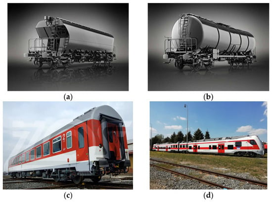
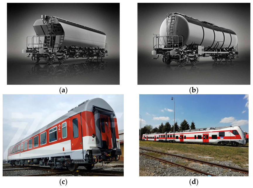
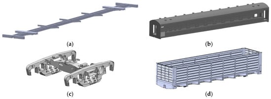
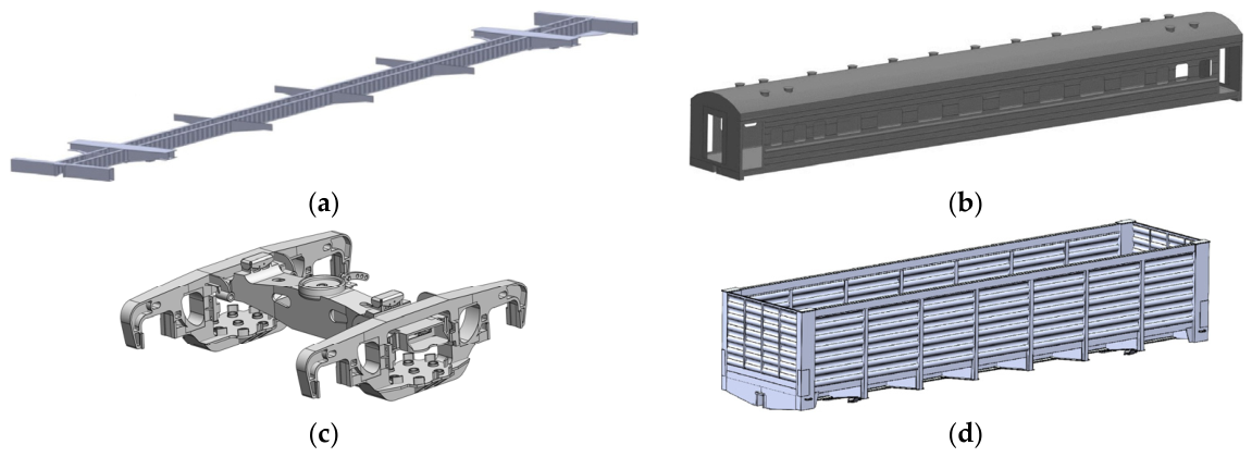
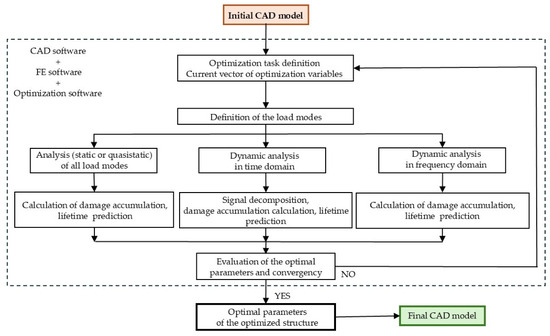
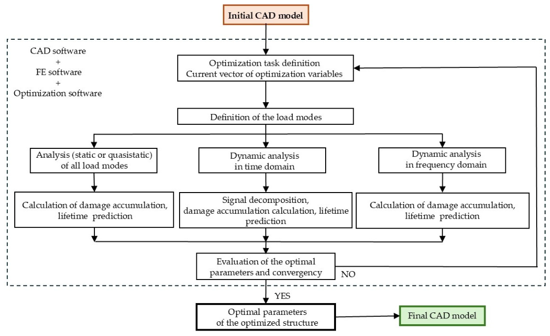
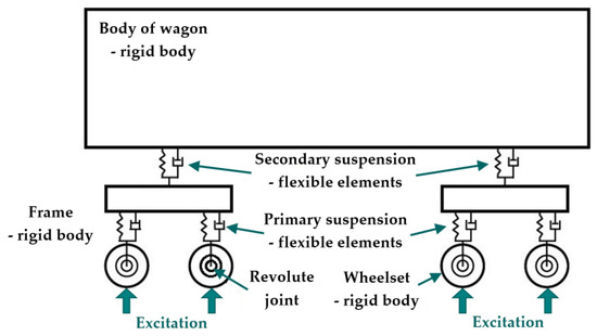
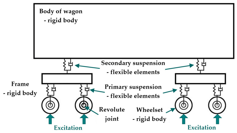
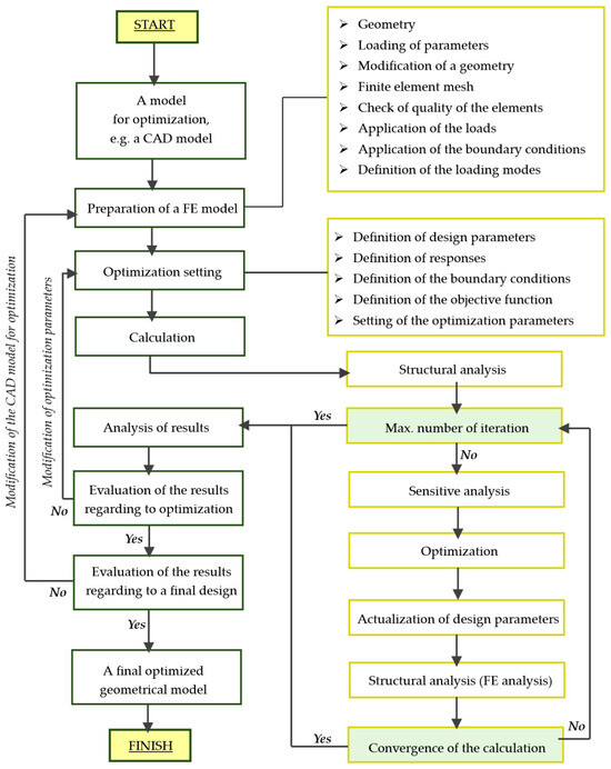
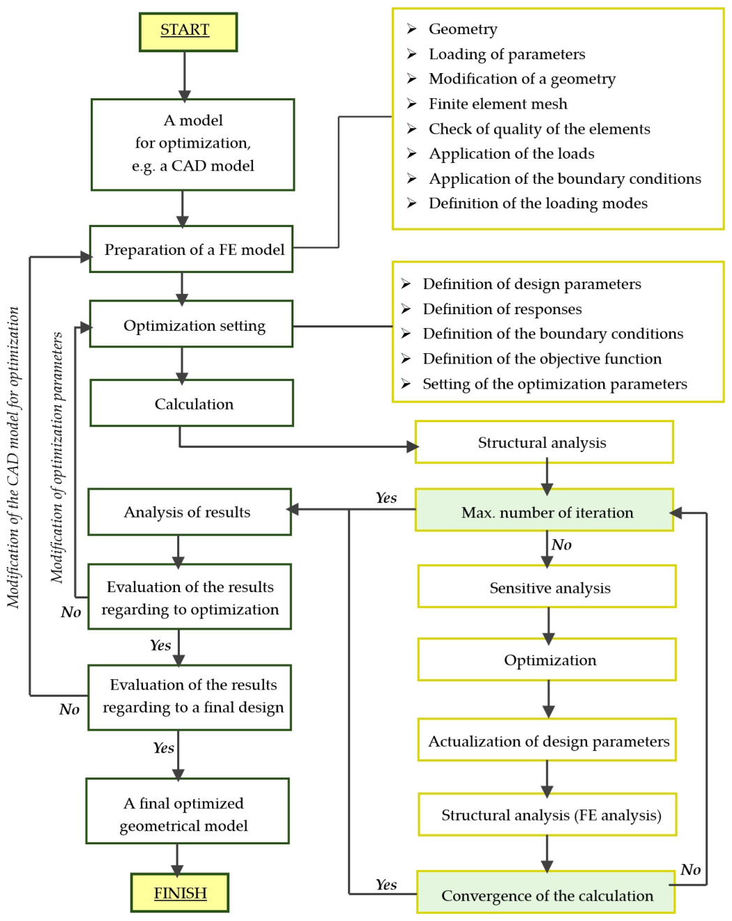
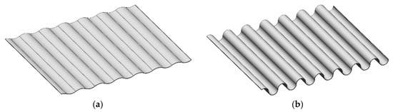
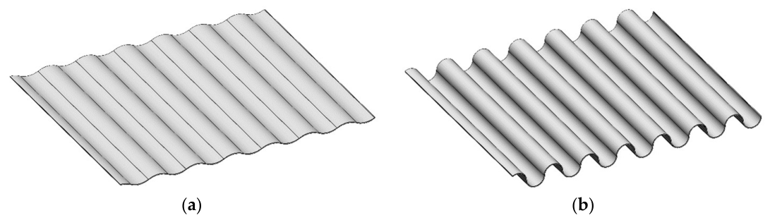
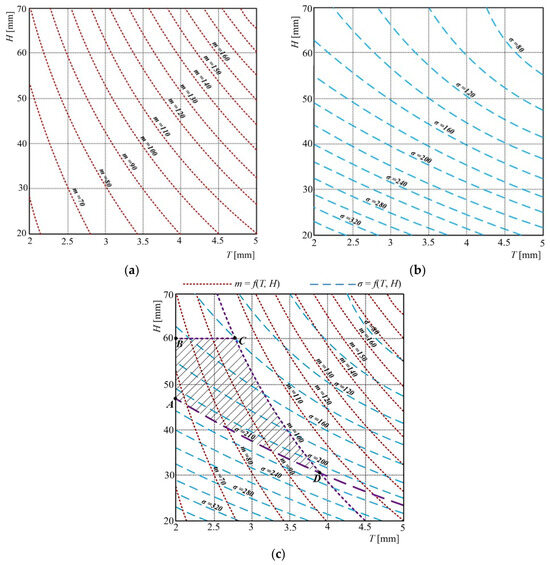
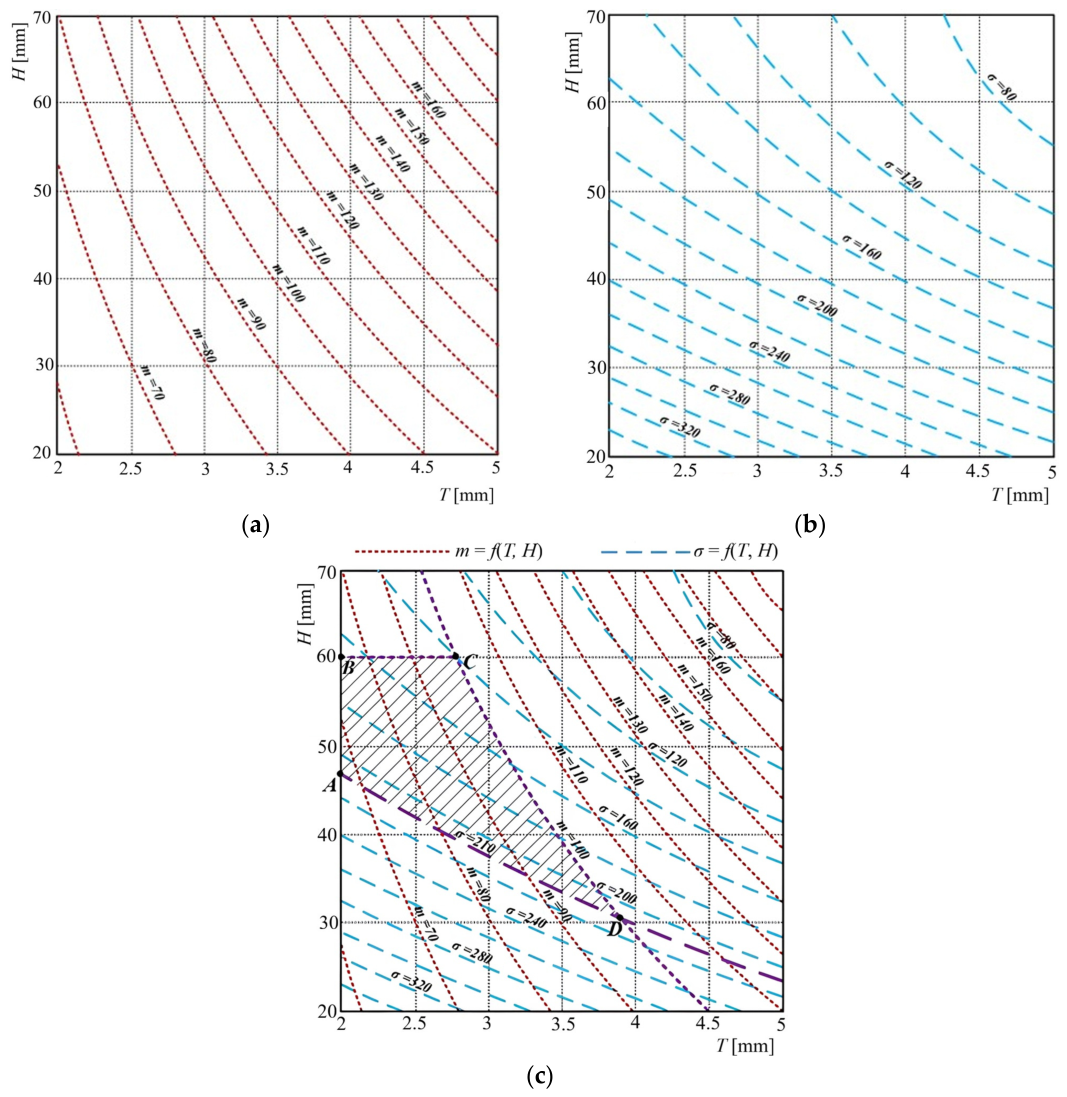
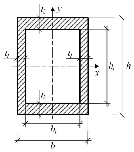
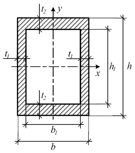
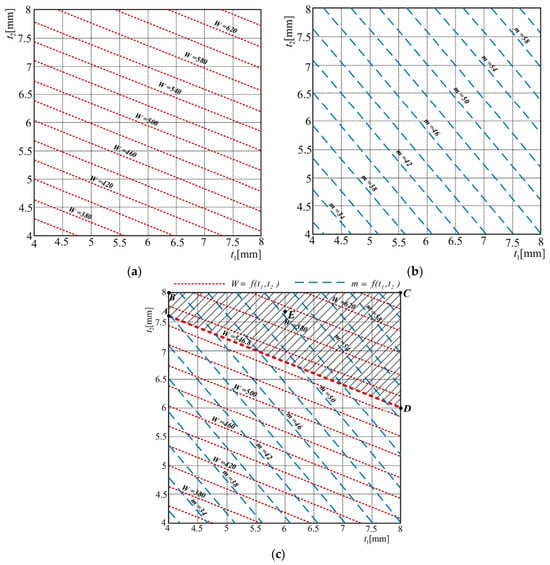
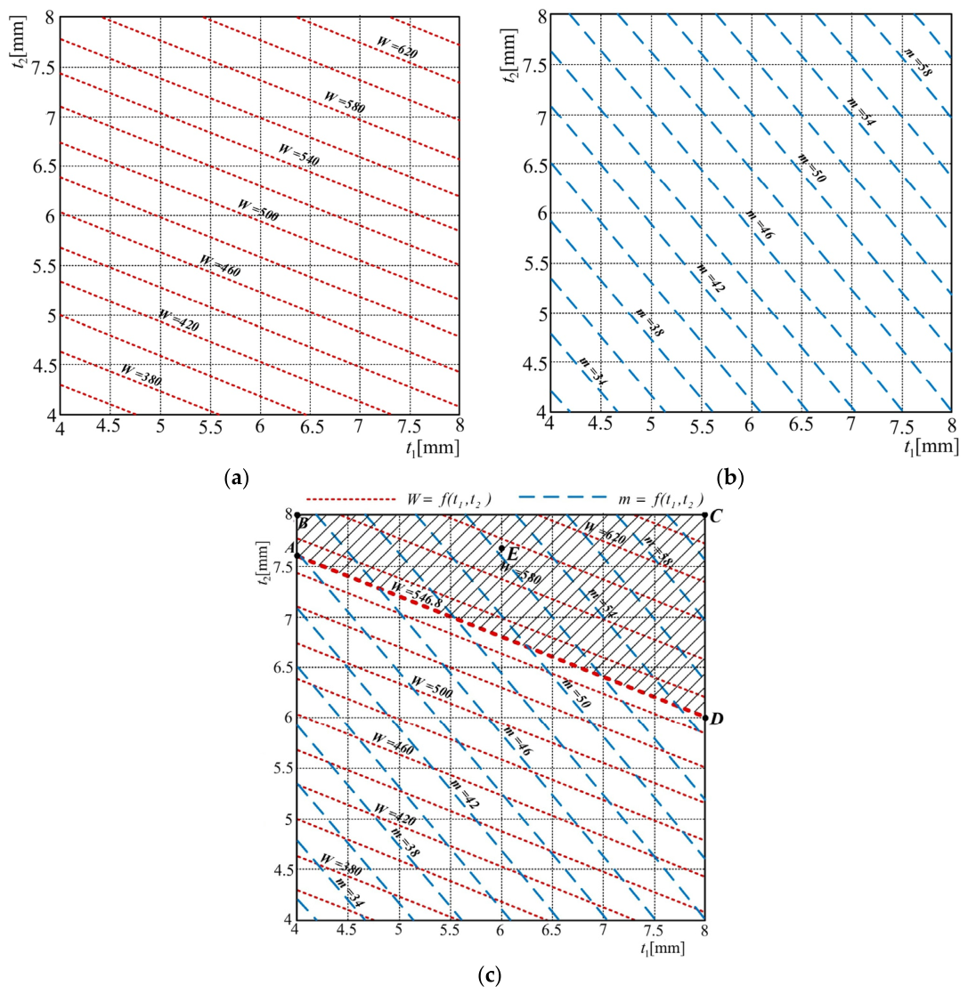
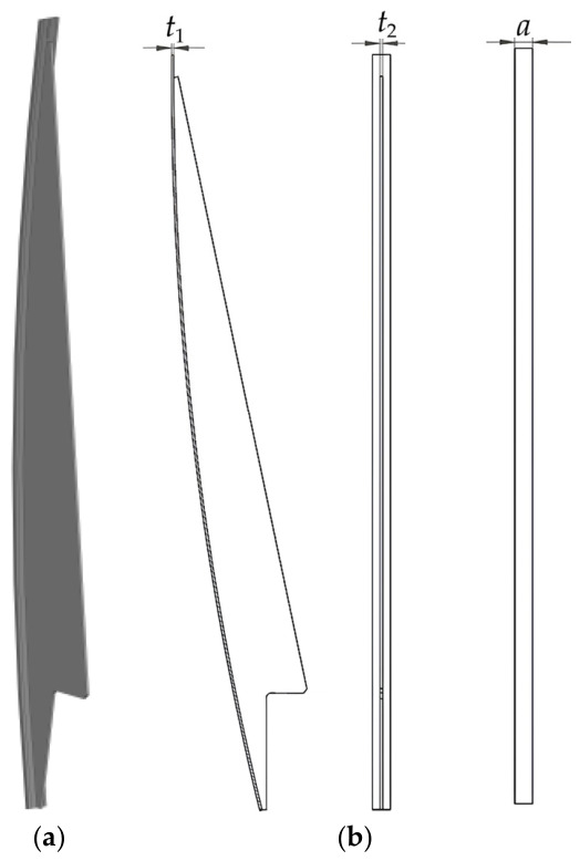
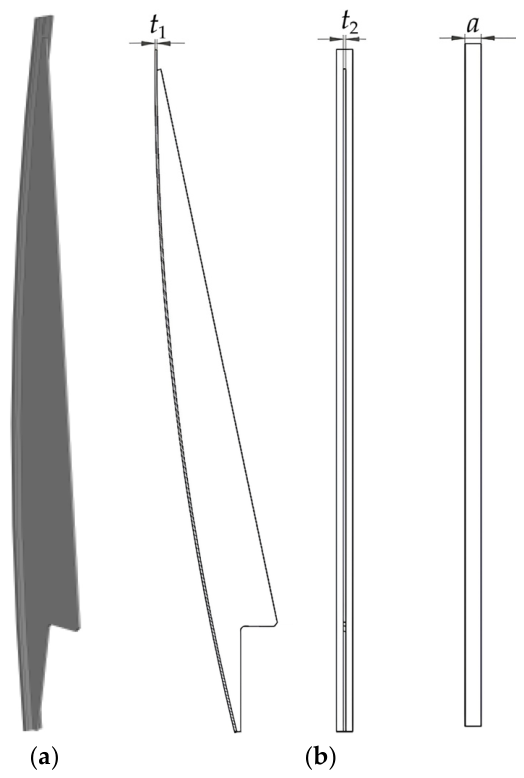
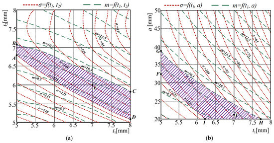
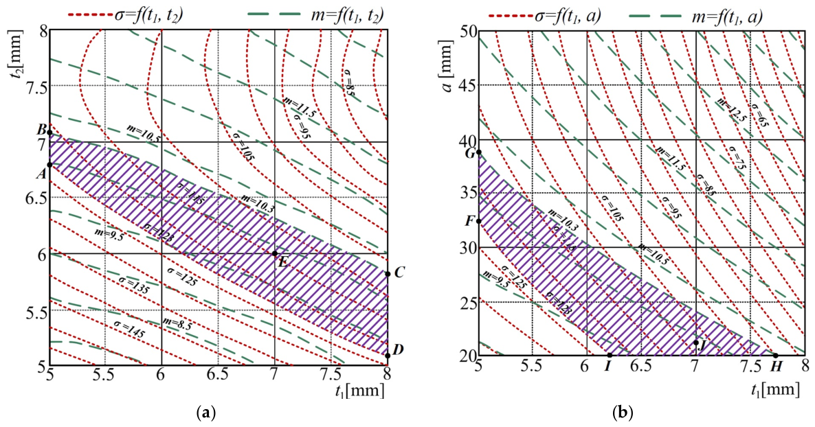
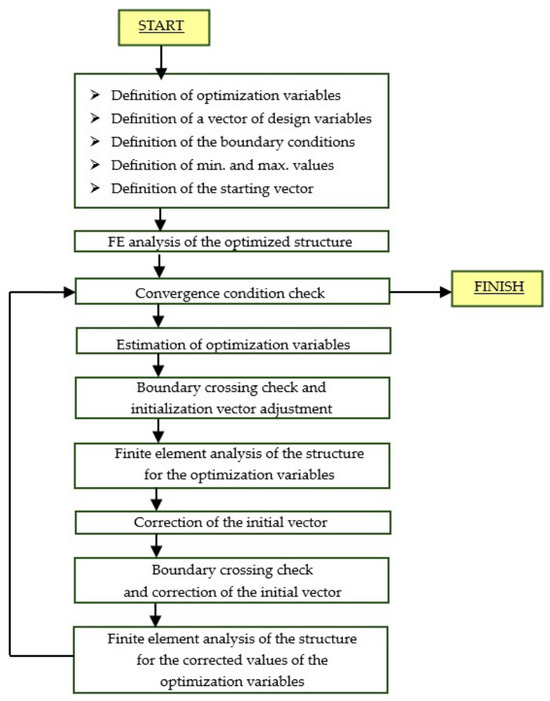
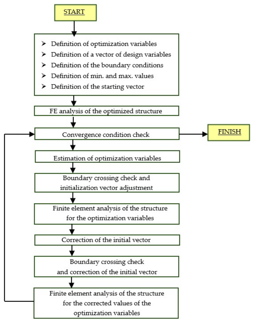

Disclaimer/Publisher’s Note: The statements, opinions and data contained in all publications are solely those of the individual author(s) and contributor(s) and not of MDPI and/or the editor(s). MDPI and/or the editor(s) disclaim responsibility for any injury to people or property resulting from any ideas, methods, instructions or products referred to in the content. |
© 2026 by the authors. Licensee MDPI, Basel, Switzerland. This article is an open access article distributed under the terms and conditions of the Creative Commons Attribution (CC BY) license.