


Abstract
Measurement-device-independent quantum key distribution (MDI-QKD) eliminates detector side-channel attacks by relocating all measurements to an untrusted intermediate node. However, its practical implementation critically relies on picosecond-level temporal synchronization between spatially separated users. In this work, we present a physically motivated autonomous synchronization algorithm for fiber-based MDI-QKD networks that does not require auxiliary optical channels or shared clock references. The method exploits round-trip optical pulse propagation and statistical signal detection in the presence of Gaussian noise. We derive analytical expressions for false-alarm probabilities, quantify detection reliability, and demonstrate through numerical modeling that a scanning resolution of 10 ps is achievable for channel lengths of up to 100 km with realistic optical power levels. The actual timing accuracy is limited by detector, source, and electronic jitter and is not quantified in this work. The proposed approach improves the scalability and robustness of MDI-QKD architectures and is directly applicable to metropolitan and backbone quantum networks.
1. Introduction
Quantum key distribution (QKD) provides information-theoretic security based on fundamental quantum-mechanical principles [1,2,3]. Among existing protocols, measurement-device-independent QKD (MDI-QKD) has emerged as a particularly robust architecture, as it closes all detector side channels by design. In MDI-QKD, both users transmit quantum states to an intermediate node that performs Bell-state measurements, which may be fully untrusted without compromising security [4,5].
Despite this conceptual advantage, MDI-QKD imposes exceptionally stringent technical requirements on temporal and phase synchronization. Successful two-photon interference at the central beam splitter requires optical pulses generated by independent laser sources to arrive within a narrow temporal window, typically on the order of several picoseconds. Any residual timing mismatch directly reduces Hong-Ou-Mandel interference visibility and degrades the secure key rate.
In deployed fiber networks, synchronization is challenged by environmental perturbations such as temperature-induced fiber-length fluctuations, acoustic vibrations, and slow mechanical drift. Existing synchronization techniques often rely on additional optical fibers, high-power reference signals, or centralized clock distribution, which limit scalability and practical deployment. These limitations motivate the development of autonomous synchronization methods that are physically robust and compatible with untrusted network nodes.
Similar challenges of lightweight authentication and key agreement arise in industrial IoT, where Ascon-based group authentication provides non-linkability and integrity [6]. In smart healthcare, lattice-based certificateless signcryption with blockchain has been proposed for secure data sharing [7]. Although these works address different application domains, they highlight the general need for lightweight, autonomous security mechanisms in distributed systems.
2. MDI-QKD Synchronization Constraints
In a standard fiber-based MDI-QKD configuration, Alice and Bob independently generate weak coherent pulses and transmit them to a central node, Charlie. Charlie performs partial Bell-state measurements using a beam splitter and single-photon detectors. The probability of successful interference depends on the temporal overlap, spectral indistinguishability, and phase coherence of the incoming pulses.
The MDI-QKD protocol was created as a response to vulnerabilities in measurement components in quantum cryptography [8]. Traditional QKD systems are susceptible to detector attacks; however, in the new architecture, measurements are placed in a separate node, allowing communication channel security to be maintained even if the measurement equipment is compromised [9,10,11]. The system involves three main components: two legitimate users (Alice and Bob), an intermediate node (Charlie), and a classical communication channel. This architecture enables security-critical measurements to be performed in a potentially insecure environment without compromising the confidentiality of transmitted data [12,13,14].
Legitimate users independently generate sequences of coherent states with different intensity levels [15]. Information is encoded in randomly selected bases prior to transmission. A feature of the MDI protocol is the use of three types of states with different intensities, providing resistance to attacks using fake states [16]. The prepared states are transmitted via quantum channels to the intermediate node, where photon interference occurs. A key requirement is strict synchronization of photon arrival from both users, ensuring correctness of the interference pattern [17]. The intermediate node performs measurements in the Bell basis using single-photon detectors and a time-coincidence registration system. Measurement results, namely detector coincidence events, are transmitted via the public channel without disclosing which specific detectors registered photons [18]. At the final stage, users select events where both transmitted signal states match by comparing used bases via the public channel, and form a raw key from events with matching bases. The final stage is error correction and privacy amplification, which yields the final secret key [19].
The problem of ensuring precise temporal and phase synchronization remains a major technical challenge in the implementation of practical measurement-device-independent quantum key distribution (MDI-QKD) systems [20]. Analysis of synchronization methods shows that accuracy requirements in MDI-QKD are significantly more stringent than those of classical quantum communication systems. Modern approaches to temporal synchronization demonstrate evolution from classical reference pulse transmission schemes to hybrid solutions. Research shows that combining wavelength division multiplexing (WDM) with adaptive filtering algorithms allows achieving synchronization accuracy up to 10 ps in metropolitan networks up to 50 km long [21]. At the same time, an acceptable level of quantum noise is maintained, confirmed by experimental data obtained under real operating conditions. In the field of phase synchronization, a transition to systems with predictive drift compensation is observed. Works [22,23] demonstrate the effectiveness of using machine learning to predict temperature changes in fiber-optic lines. Quantum synchronization methods are considered a promising direction. Experimental studies [24] confirm the possibility of using temporal correlations in entangled photon pairs for synchronization with accuracy up to 100 fs. However, practical implementation of such systems requires overcoming significant technological barriers related to the complexity of generating and detecting entangled states in field conditions.
The most common method for time coordination of nodes in fiber-optic MDI-QKD systems is using a single master frequency generator for all participants. In this configuration, the generator is usually placed at Charlie’s device and connected by electrical cables to the control modules of Alice and Bob. This synchronization method has proven effective in laboratory conditions for testing system principles. However, a key drawback of this approach is that Alice’s and Bob’s devices cannot be placed far from Charlie’s. Thus, although the method is ideal for testing, it is unsuitable for commercial deployment. The second method is based on calculating the cross-correlation between sent and received qubit sequences [25]. Its weak point is the requirement to use single-photon detectors—the most technologically complex element in modern quantum key distribution systems. The third approach involves using powerful optical pulses transmitted via the quantum channel or a separate fiber. Using an additional fiber complicates the system architecture. Patent [26] describes a system and method for compensating the time shift of optical pulses in quantum channels of a quantum key distribution device with an untrusted central node. The system proposed by the patent authors is based on using an adjustable optical delay line in one of the untrusted node inputs, included in a feedback loop with single-photon detectors, allowing control of laser pulse overlap at the beam splitter of the untrusted node with accuracy up to units of picoseconds. It is assumed that this solution should improve interference in real operating conditions, thereby increasing the maximum distance and the secret key generation rate. Patent [27] describes a quantum key distribution system with an untrusted central node and a method for preparing quantum states for the quantum key distribution protocol with an untrusted central node. The work presents an approach using passive phase randomization (i.e., without a phase modulator) while ensuring a high interference quality. A theoretical description of the proposed method and experimental comparison with the existing method based on a continuous-wave laser are presented. Patent [28] describes a synchronization device for quantum key distribution systems operating on side frequencies in a star topology. Synchronization here uses a separate optical fiber, a pulsed coherent distributed feedback laser source, and a beam splitter. Interesting research is described in another article [29], proposing a method for automatically adjusting Alice’s and Bob’s frequencies to Charlie’s frequency. The work demonstrates a frequency synchronization protocol for MDI-QKD setups using a laser and a 50/50 beam splitter for synchronization signal transmission, as well as a phase-locked loop for computing the control signal value.
3. Autonomous Synchronization Algorithm
The proposed synchronization algorithm adapts concepts from autocompensating QKD systems to the MDI-QKD topology. Each user station is equipped with an optical circulator and a classical photodetector, while the untrusted node contains weak tap couplers and reflective elements. No trusted hardware or timing reference is required at the central node.
Each station independently performs a round-trip time-of-flight measurement by transmitting optical pulses toward Charlie and detecting the reflected signal. The detection process is formulated as a statistical hypothesis test in discrete temporal windows. Importantly, all temporal windows are scanned, and the window with the maximum number of detections is selected as the signal window.
The pulse repetition period T is chosen to operate in the wait-for-reflection regime, where . In this regime, the next optical pulse is transmitted only after the reflection of the previous pulse has been detected, so reflected pulses from different frames do not overlap. For a 100 km link, ms; therefore, we set ms. Because only one reflected pulse is present in the fiber at any given time, every measurement is trivially associated with the transmitted pulse that produced it.
After both users determine their respective propagation delays, Charlie compares the measured arrival times and computes a relative temporal offset. One station then applies a compensating delay by adjusting the emission timing of its laser pulses. Fine alignment is achieved by monitoring two-photon interference visibility.
The synchronization process in quantum key distribution systems is a set of procedures aimed at establishing and maintaining temporal correspondence between distributed system nodes. Its fundamental task is to ensure the coherent interaction of single-photon signals propagating along independent optical paths. Without precise synchronization, correct interference of photon states, which is the basis of the MDI-QKD protocol, becomes impossible. From the perspective of optical signal detection, synchronization solves the task of identifying time windows in which single-photon states are expected to arrive. Signal search is performed through the analysis of temporal correlations between detected events and reference clock sequences.
For MDI-QKD, maintaining synchronization under conditions of phase drifts and temperature variations affecting optical signal propagation paths is particularly challenging. Stabilization of relative phase shifts requires creating feedback systems that continuously compensate for changes in path difference between interfering signals. In systems with long fiber-optic lines, synchronization is additionally complicated due to group delay instabilities caused by mechanical stress and temperature gradients. Overcoming these limitations requires developing specialized time coordination protocols adapted to real telecommunication channel conditions. Successful implementation of such protocols enables building scalable quantum networks with guaranteed security parameters.
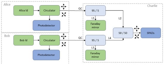
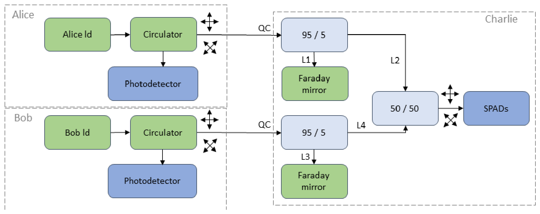
We modified the synchronization algorithm used in two-pass auto-compensation QKD systems [30] for the MDI-QKD topology and made minor changes to station design. A feature of the algorithm is its autonomy, i.e., the ability to perform synchronization without coordinating data via a public (service) communication channel between stations. Figure 1 and Figure 2 show schematic diagrams of optical parts of distributed QKD systems using polarization and phase encoding. Optical circulators and photodetectors are added to Alice’s and Bob’s station designs. Beam splitters are added to Charlie’s station’s input path, diverting part of the radiation to reflective mirrors.
Figure 1.
Optical part of MDI-QKD scheme with polarization encoding.
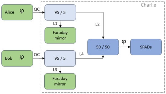
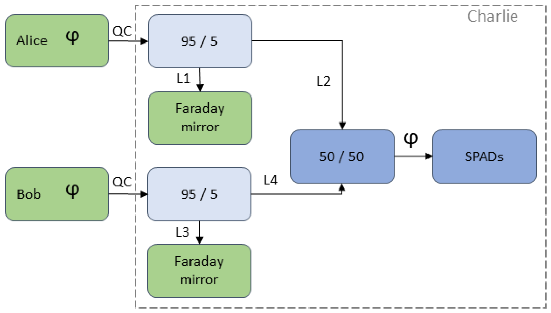
Figure 2.
Optical part of the MDI-QKD scheme with phase encoding. A classic configuration that includes: radiation source; photodetector; optical beam splitter; avalanche photodetectors; X-type beam splitter; 95/5—Y-type beam splitter; mirror for reflecting the optical signal; polarizing beam splitter; optical circulator; L—optical arms; QC—quantum communication channel.
Figure 2 shows the optical path diagram of the MDI-QKD system using phase encoding of photon states.
Beam splitters are also integrated into Charlie’s node design, and optical circulators with photodetectors are used in Alice’s and Bob’s stations. For phase encoding, the circulator can be placed directly in one interferometer arm, or the photodetector can be connected to one interferometer beam splitter input. When diverting optical radiation from one interferometer arm, we unambiguously fix a pulse at the photodetector. The situation changes when connecting the photodetector to one beam splitter output. Here, detection will depend on the interference pattern (outcome). Alternatively, an optical circulator can be installed between the interferometer and the radiation source (not shown in figure). In this case, signal detection will occur unambiguously.
An optical signal with wavelength 1550 nm enters the Mach–Zehnder interferometer beam splitter of the Bob station, where it splits into two equal power pulses. Following different arms, the pulses enter the quantum channel with a time delay. At Charlie’s station input, pulses enter a beam splitter where a smaller part of the energy is diverted to an optical mirror and reflected. During backward propagation, the signal enters the optical circulator in the interferometer arm (Figure 2) and is registered by the photodetector. Charlie’s station electronics must know when to activate avalanche photodetectors to record the interference result of signals arriving at the beam splitter. Alice and Bob stations must know the exact distance to the main beam splitter in Charlie and the exact pulse generation time for each station. This is required so that single photons from Alice and Bob arrive at Charlie’s beam splitter simultaneously. The scanning step of the synchronization algorithm is 10 ps; the residual timing error depends on jitter and is not quantified here. Since stations are located at different distances from Charlie, we propose performing time correction (delay) of signals by adjusting radiation sources. Charlie’s electronics know the exact lengths of its interferometer arms and thus can activate SPDs at the right moment with the required time delay relative to signal arrival at the beam splitter. This delay value will be constant for a specific Charlie implementation. Furthermore, optical path lengths from the 95/5 beam splitter to the interferometer beam splitter and from the 95/5 beam splitter to the reflecting mirror must be equal (L1, L2 and L3, L4). Knowing the optical pulse travel time from the radiation source to the reflecting mirror and back to the photodetector, the Alice and Bob stations can independently determine distances to Charlie’s beam splitter. Note that with the 95/5 beam splitter electronically controlled, this electronically controlled version can be used to disable the necessary optical signal output (e.g., disable output to the reflecting mirror during quantum protocol operation).
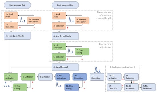
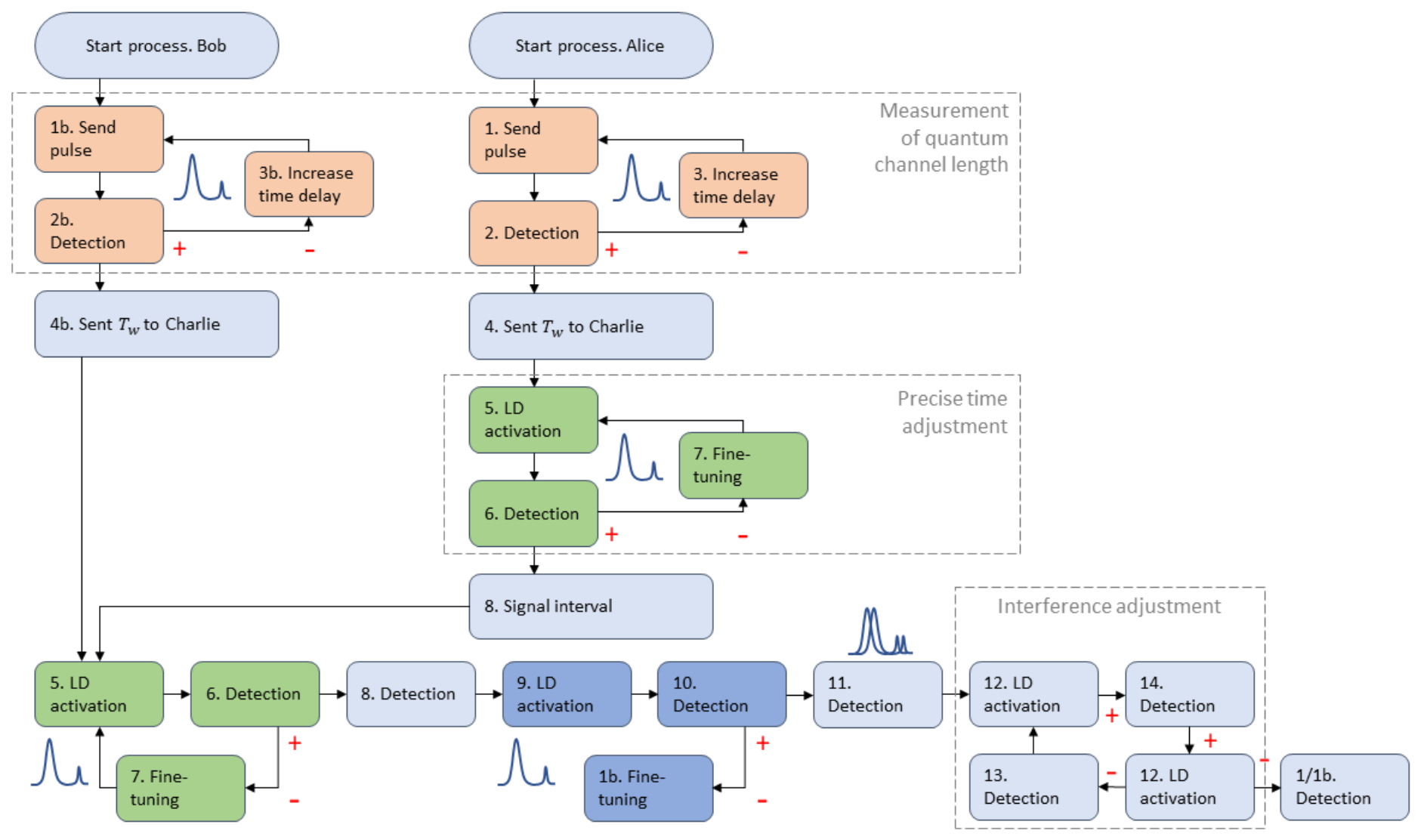
Consider the synchronization process scheme through a sequential algorithm of events (Figure 3).
Figure 3.
Synchronization process of stations in the MDI-QKD configuration. Symbols + and − mean positive and negative condition (event) results.
The entire process can be divided into several stages: Alice measures quantum channel length; Bob measures quantum channel length; Alice informs Charlie of the obtained data; Charlie performs gating and adjustment based on Alice’s data; Bob informs Charlie of the obtained data; Charlie performs gating and adjustment based on Bob’s data; Charlie computes the delta between signals from Alice and Bob and informs one station. All participants perform precise time adjustments.
Blocks 1–3 in Figure 3 reflect the process of measuring distance to Charlie’s beam splitter. Distance is expressed through time with a scanning resolution of 10 ps. This process is implemented through sequential analysis of time intervals with a stepwise increase of the detection time delay for the Alice station photodetector. 1—pulse sending; 2—detection result in a specific time interval; 3—increase of detection time delay. After determining the signal time window, Alice transmits data about the pulse repetition period to Charlie (4) and sends a command to activate SPD (5). Charlie’s electronics now knows the pulse repetition period from Alice and, receiving the command, activates the photodetector. The first registered signal from Alice starts Charlie’s cyclic adjustment (5–7). Such adjustment is implemented through sequential analysis of adjacent time intervals relative to the known gating time. The algorithm assumes analysis of intervals of 10 ps duration with time shift ± 2 ns, which defines the scanning resolution of the refinement stage. The operation result will be the interval with the signal pulse (8). For the unambiguous selection of one narrow time interval, multiple checks of each time window are used. Success of stage (block 8) means that Alice knows the exact optical pulse travel time to Charlie’s beam splitter, and Charlie possesses information about the exact arrival time of Alice’s pulses at the SPD. We can say that at this intermediate stage, Alice and Charlie are synchronized.
By this time, the Bob station has already passed stages 1–4, i.e., possesses information about pulse propagation time to Charlie’s beam splitter. Now stages 5–8 repeat for the Bob station. The Alice station does not stop. An electronically controlled beam splitter blocks pulses arriving from Alice’s to Charlie’s station. At stage 9, Charlie, knowing arrival times of pulses from Alice and Bob, computes the time delta (Figure 5) and transmits its value to Bob for correction (introducing time delay). Block 10 compares delta, i.e., whether pulses from Alice and Bob arrive simultaneously. At this stage, Charlie’s electronics controls the beam splitter outputs, switching them alternately. The latter is done for more precise adjustment. After coordination, at stage 11 both beam splitter outputs open and pulses from Alice and Bob enter Charlie’s station. Then, at stage 12, interference presence is recorded. If interference is present, synchronization is successful. If absent, Charlie performs fine adjustment within . If the result is negative, calibration steps are repeated (1/1b).
Consider the physical and mathematical models of the distance measurement process to Charlie’s beam splitter from one station (blocks 1–3 in Figure 3). The optical path from a station, e.g., Bob, to Charlie’s beam splitter (and hence to SPD) and back structurally corresponds to an auto-compensation quantum key distribution system scheme. In such systems, the task of optical signal search is solved by a known method [31]. Our works provide a detailed description of the synchronization algorithm for such QKD systems and propose various improvement options [32].
Pulse duration , and time window duration . The number of time windows accordingly equals Since classical photodetectors are used in Alice and Bob stations, the signal is described by a normal distribution (Gaussian distribution). To decide signal presence, threshold P is set for the photodetector amplitude. If the measured signal exceeds this threshold, a decision is made about its presence. Reflected signal search is performed by sequential analysis of all . In an idealized version, the algorithm provides continuous sequential analysis of all time windows, but in real systems, the photodetector requires recovery time up to 100 ns, so after each pulse sending one time window is analyzed. The main source of false alarms in this case is photodetector dark current and amplification noise (e.g., shot noise, thermal noise). These noises are random and in our case also described by normal distribution. The probability that a noise sample exceeds trigger threshold in one time window is computed via the Gaussian Q-function [33] and considers the noise standard deviation :
Since we have N independently polled time windows, the probability that no false alarm occurs in any of them equals the product of probabilities for each window:
Consequently, the probability that at least one false alarm occurs per period equals
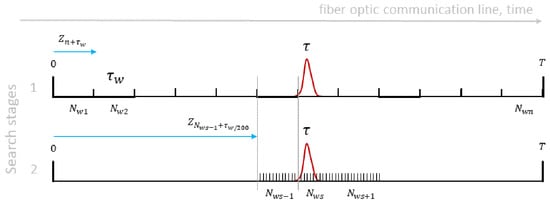
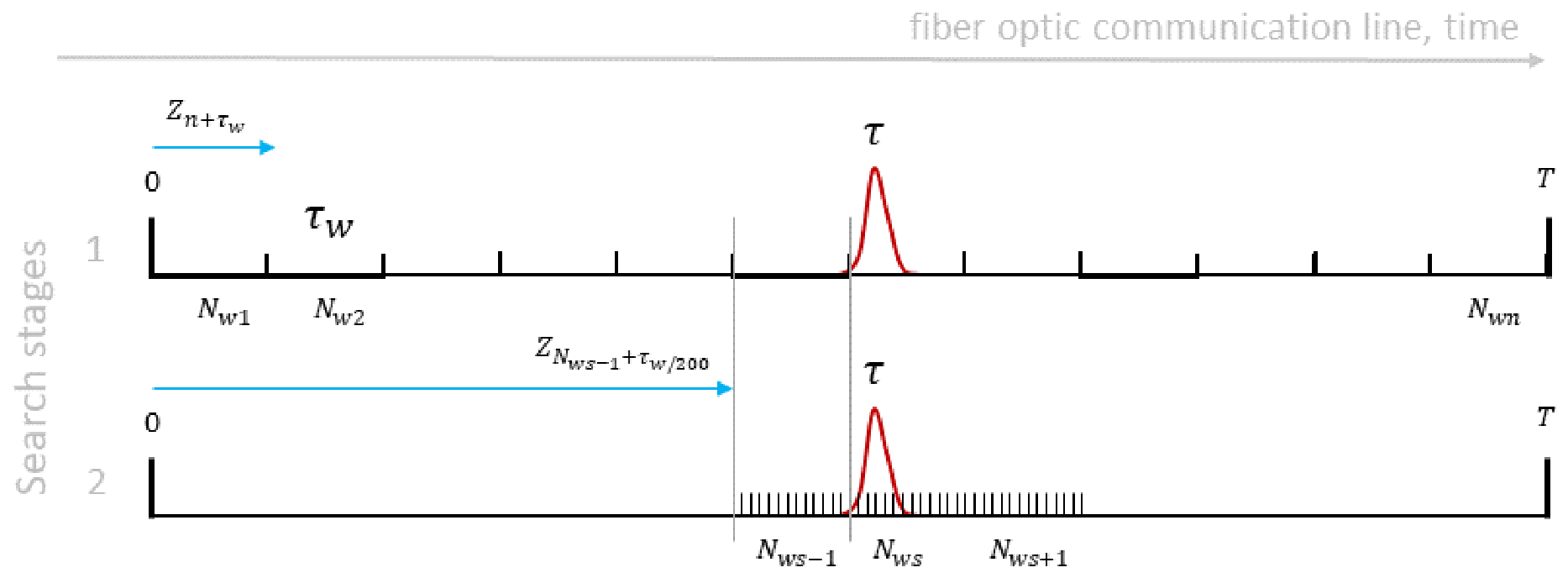
Formula shows that exponentially depends on ratio . Even a slight threshold increase sharply reduces false alarm probability. In contrast to the early-termination scheme used in autocompensating QKD systems, the proposed algorithm analyzes all time windows and selects the one with the maximum number of detections (Figure 4).
Figure 4.
Signal time window search.
At the first search stage after each pulse sending , one time window is analyzed. The time delay Z sequentially increases by value
At the first (coarse) stage, the algorithm can operate in two modes. During the initial system installation (or full calibration), all time windows that make up the pulse repetition period are scanned. However, this full scan is typically performed only once. After the initial calibration, the algorithm knows the approximate position of the signal window and switches to a fast-search mode, analyzing only a limited subset of windows around the expected position. In either mode, the search does not stop at the first detection. Instead, each window is polled times, with exactly one poll per frame of duration T, and the window with the maximum number of detections is selected as the signal window. Because the search is not terminated by an individual detection, a false alarm in one window does not interrupt the scan; multiple polling combined with the maximum-selection rule reduces the effective false-alarm probability to a negligible level, so that the probability of correctly acquiring the signal window, , approaches unity and is not limited by false alarms. The total coarse-search time is, therefore, .
After detecting the signal time window , search stops and the algorithm proceeds to second (refinement) stage. Here, time intervals are split into subintervals of duration , i.e., 10 ps. Error margin in is taken to account possible signal shift due to, e.g., external destabilizing factors affecting optical fiber. The operational result for blocks 1/1b–3/3b (Figure 3) will be the knowledge of pulse travel time to Charlie’s beam splitter with a scanning resolution of 10 ps.
Blocks 5–7 are responsible for adjusting Charlie’s SPD after one station sends data about the pulse repetition period. After Charlie’s photodetector is ready to receive pulses, one station activates the laser diode, and the first received signal starts the cyclic adjustment process. The adjustment algorithm is similar to the procedure of stage 2 in Figure 4. The gating pulse is located in time window , and the analysis process begins with stepwise scanning of each interval of duration .
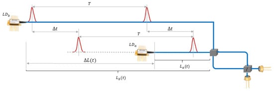
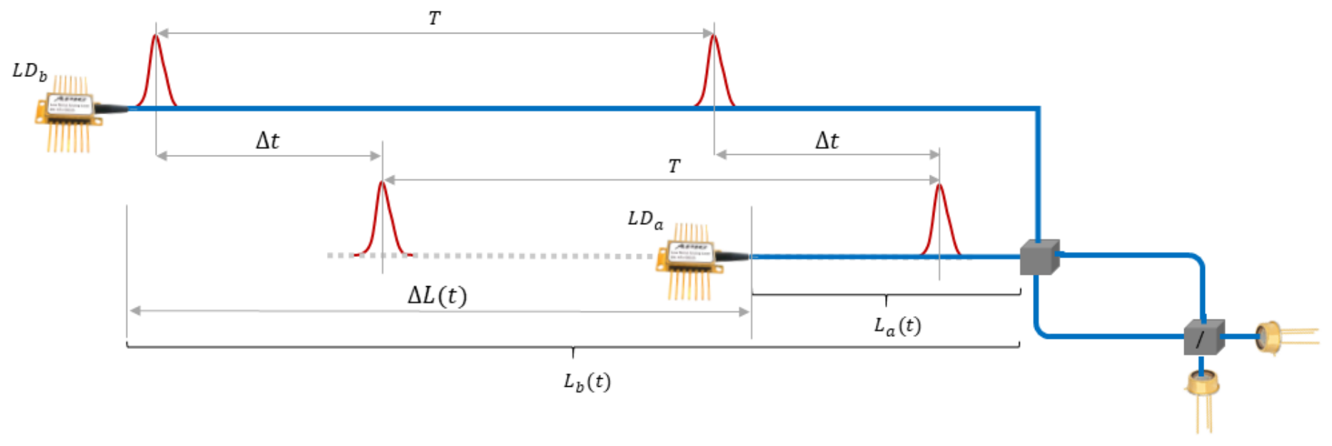
Figure 5 shows a time diagram of pulses arriving at Charlie’s beam splitter (photodetector) at different times. Naturally, the time difference with the same repetition period is caused by different quantum channel lengths. After computing the time delay between pulses, Charlie sends data to one station. Technically, the compensation delay is performed by shifting the laser diode activation time. The operation repeats until synchronization of the two signals with a scanning resolution of 10 ps is achieved. Note that for the two-signal condition, the equality of repetition period must be satisfied. Phase adjustment for obtaining interference is performed using a similar method (Figure 4), but with a scanning step of 60 ps.
Figure 5.
Optical signal desynchronization.
4. Statistical Detection Model
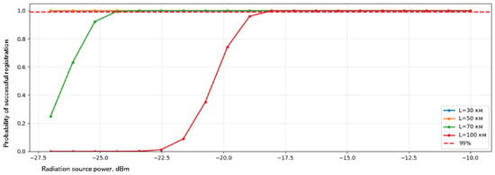
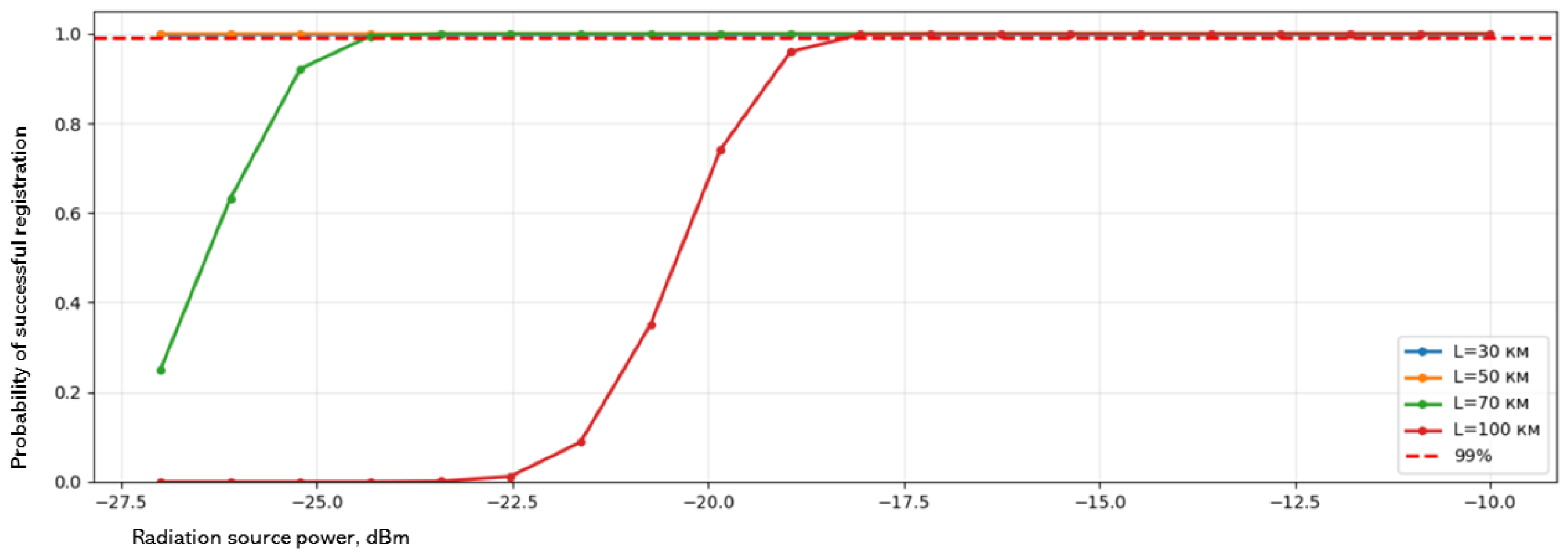
The signal model, noise parameters, detection threshold, and loss model used here are the same as in our previous works [30,32], where they are described in detail. A detailed study of the dependence of the detection probability on launch power and channel length for various simulation parameters is also presented in our previous works [30,32]. In the present paper, we rely on these results and use them as input for the synchronization-time model. It should be noted that the values reported in Table 1 correspond to a single poll of the correct temporal window, whereas Figure 6 shows the overall detection probability after multiple polling. Because each window is polled several tens of times in the proposed algorithm, the overall probability of successful detection approaches unity even for a 100 km link, which explains the near-unity values seen in Figure 6.
Table 1.
Parameters and mean coarse-search acquisition time for the fast-search mode (after initial calibration).
Figure 6.
Overall detection probability after multiple polling as a function of radiation power for different fiber lengths.
Let us simulate the proposed algorithm for detecting the signal time window using the initial data given above. Note that at the first stage, all time windows are analyzed, and the window with the maximum number of detections is selected. At the second stage, all time subintervals are analyzed. We analyzed graphs of the dependence of correct signal time window detection probability on radiation power considering different fiber lengths (Figure 6).
Simulation results show that to achieve a probability above 99% at fiber length 100 km, sufficient conditions can be achieved using an optical emitter power of dBm. If we consider a quantum channel length of less than 50 km, a radiation power of dBm will provide 100% detection probability. The simulation used a photodetector quantum efficiency of 20%, fiber attenuation of dB/km, and losses of dB at each connector adapter.
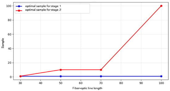
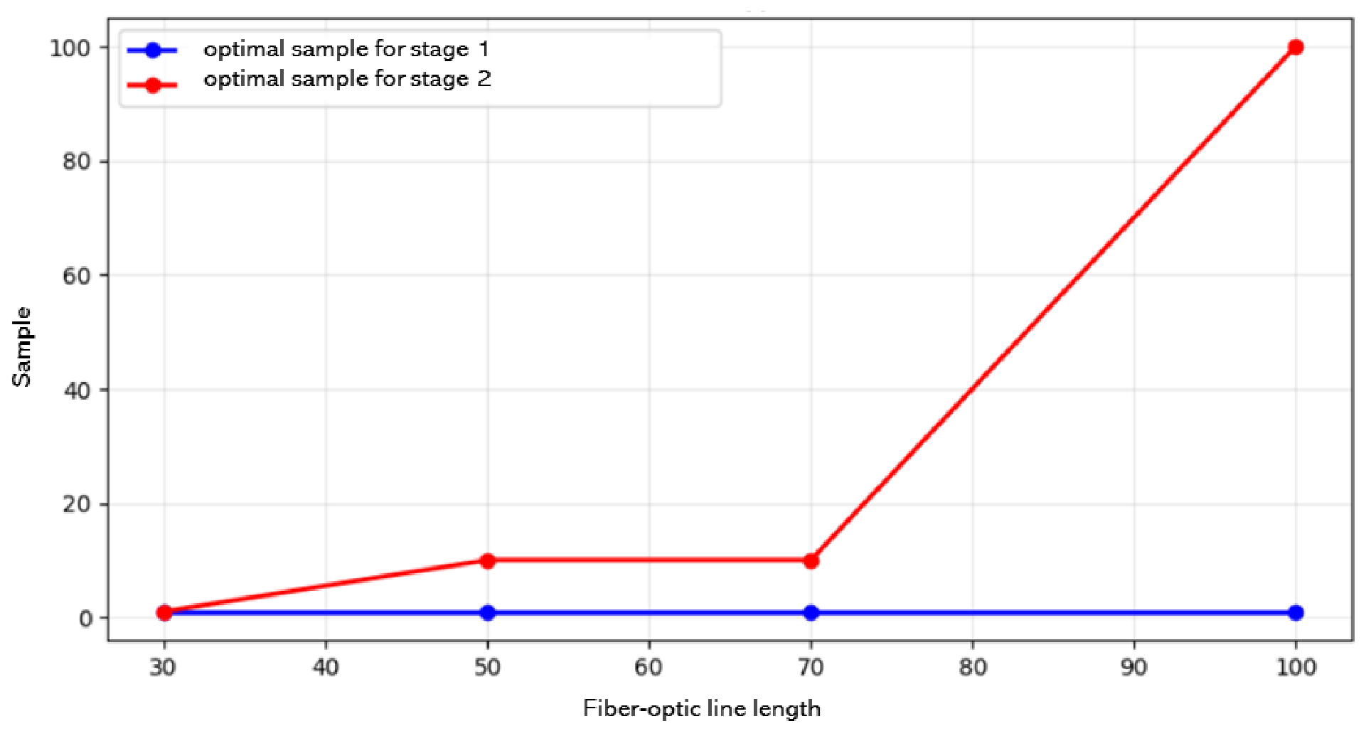
Real QKD systems use radiation sources that, in synchronization mode, have power ranging from dBm to dBm. Figure 7 presents results of analysis to determine optimal sample size in each time interval at the first and second stages at fixed laser power, , to achieve correct detection probability >99%.
Figure 7.
Dependence of sample size on fiber length.
It can be seen that, at the first stage, a sufficient condition is a single analysis of the time window for all fiber-length values. When moving to the second stage, the sample size needs clarification. Thus, to account for the maximum possible distance of 100 km, each subinterval must be polled at least 100 times.
The detected signal amplitude is modeled as a Gaussian random variable, reflecting dominant contributions from thermal and shot noise. A fixed detection threshold is applied, and the probability of false detection in a single temporal window is given by
where is the threshold amplitude, is the noise standard deviation, and denotes the Gaussian Q-function,
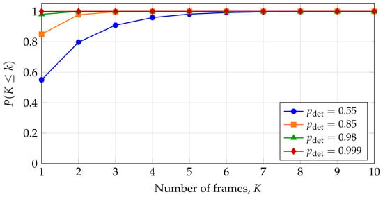
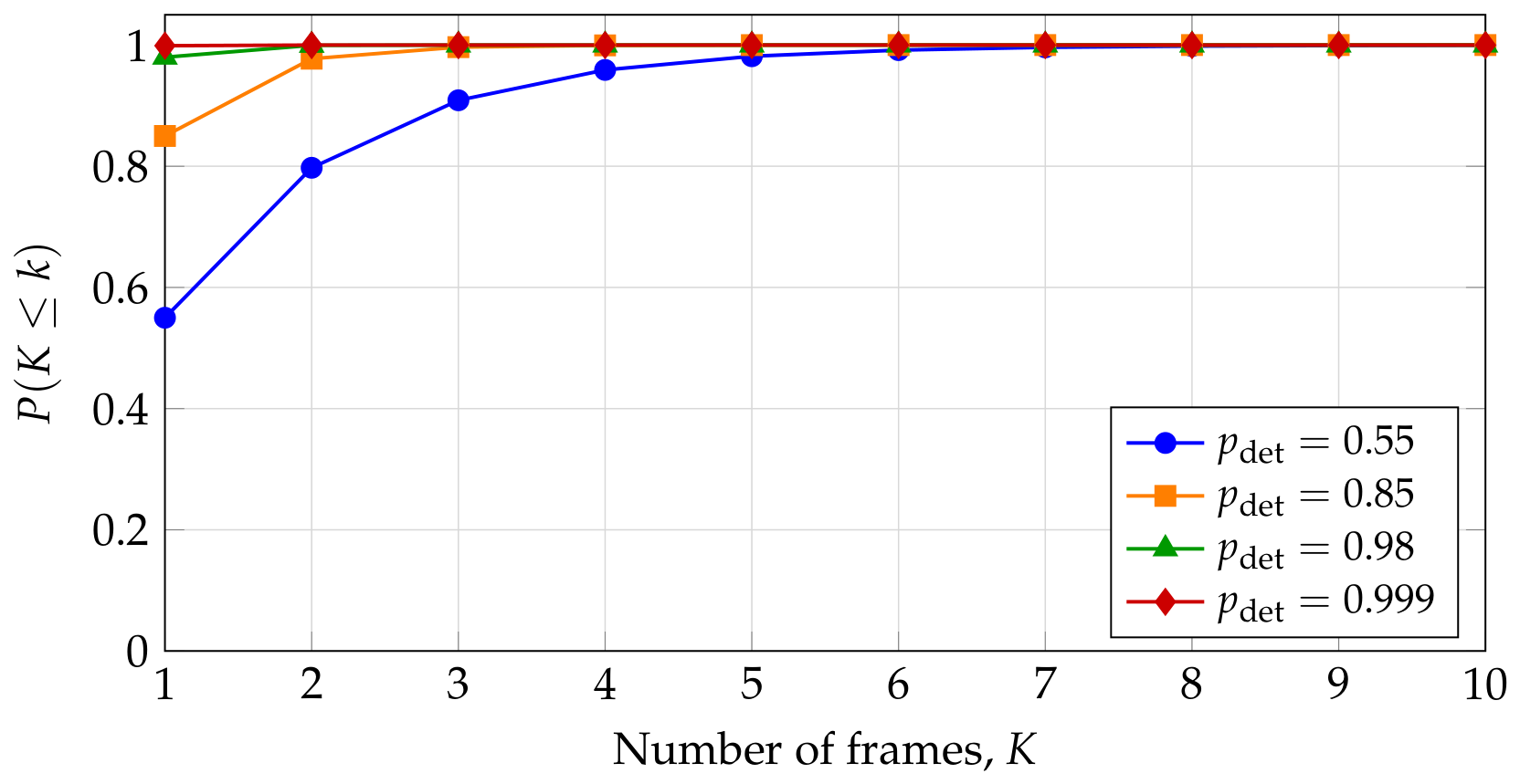
For N independently scanned windows, the probability of at least one false alarm scales as . This dependence motivates the multiple-polling and maximum-selection strategy described above. The cumulative distribution function of the number of frames required for a successful detection is shown in Figure 8 for different values of .
Figure 8.
Cumulative distribution function of the number of frames required for successful synchronization, , for different values of .
The probabilistic model developed in this work accounts for detection and false-alarm probabilities, which depend on the signal amplitude, the noise level, and the detection threshold. Timing jitter of the detector, source, and electronics is not included in this probability analysis. However, jitter does affect the temporal parameters of the synchronization procedure, such as the effective width of the search window, the resolution of the arrival-time estimate, and the residual timing error after refinement. A detailed treatment of jitter in both the probability and timing analysis is the subject of ongoing work and will be reported elsewhere.
5. Numerical Results
Monte Carlo simulations were performed assuming a detector quantum efficiency of 20%, fiber attenuation of 0.2 dB/km, and connector losses of 0.3 dB. For a 100 km fiber link, a launch power of dBm yields a detection probability exceeding 99%. For links shorter than 50 km, near-unity detection probability is achieved at dBm.
The refinement stage requires increased sampling density for longer channels. At 100 km, reliable localization of a 10 ps subinterval requires approximately 100 detection events per subwindow.
The 10 ps value reported in this work refers to the scanning resolution of the refinement stage, i.e., the step size used to localize the signal window. The actual timing accuracy is limited by the jitter of the detection chain and is not quantified in the present study. This distinction should be kept in mind when interpreting the synchronization resolution reported in the manuscript.
6. Probabilistic Analysis of Synchronization Acquisition Time
The algorithm described above relies on sequential scanning of temporal windows and selects the window with the maximum number of detections as the signal window. In practice, however, a single scan may fail because of dark counts, thermal noise, and signal attenuation in long fiber spans. The synchronization procedure must therefore be regarded as a repeated multi-frame random process. In this section, we develop a probabilistic model of this process, derive the distribution of the number of frames required for successful synchronization, and estimate the mean synchronization acquisition time.
6.1. Formalization of the Synchronization Process
Let us consider a frame (one pulse repetition period) as an independent Bernoulli trial. At the first stage of the algorithm, one temporal window is analyzed after each probe pulse. If the measured amplitude exceeds the threshold P, a signal is declared present. Let denote the probability of successful signal detection within a single frame. This quantity depends on the optical launch power, the fiber length, and the detector quantum efficiency and can be extracted from the simulation results reported in Figure 6.
It is important to note that the detection probability does not depend on the position of the time window containing the signal. The detection process is based on comparing the measured amplitude with a fixed threshold, and the signal amplitude in the correct window is determined by the optical power, fiber loss, and detector quantum efficiency. These factors are independent of where the correct window is located within the frame. Therefore, each frame can be treated as an independent Bernoulli trial with the same probability of success . The sequential scanning within a frame determines the coarse-search time , but does not reduce the probability of correctly identifying the signal window, since all windows are polled an equal number of times and the maximum-selection rule is applied.
In the presence of dark counts and noise, a single poll may fail; the procedure is therefore repeated over multiple frames. We define the coarse-search acquisition time as the total time required to poll all N temporal windows times. The mean coarse-search acquisition time is determined by the number of windows and the number of polls per window:
where T is the frame repetition period. The model assumes statistical independence of noise events across adjacent frames.
6.2. Joint Success Probability Including the Refinement Stage
The model above accounts only for the first (coarse) search stage. In the algorithm, once the signal window has been identified, a second (refinement) stage is executed: the intervals , , and are subdivided into subintervals of duration ps, and each subinterval is polled multiple times.
Let denote the probability of correctly localizing the signal window at the first stage, and let denote the probability of successful refinement at the second stage, conditioned on a correct first-stage outcome. The joint success probability of the full procedure is then
If does not meet the required target (for example, below ), the entire procedure is repeated. The expected total synchronization time is therefore the time of a single scan multiplied by the expected number of attempts:
The refinement stage is executed frame-by-frame, with each poll occupying one frame of duration T. The detector recovery time, on the order of a few nanoseconds, is well below the frame repetition period and is therefore absorbed into the frame structure.
6.3. Relation to Numerical Simulation Results
Figure 7 reports the optimal sampling volume required to achieve at a fixed launch power of dBm. For a 100 km fiber link, approximately 100 samples per subwindow are needed at the refinement stage. Substituting these values into the model allows one to estimate the mean coarse-search acquisition time.
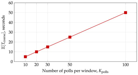
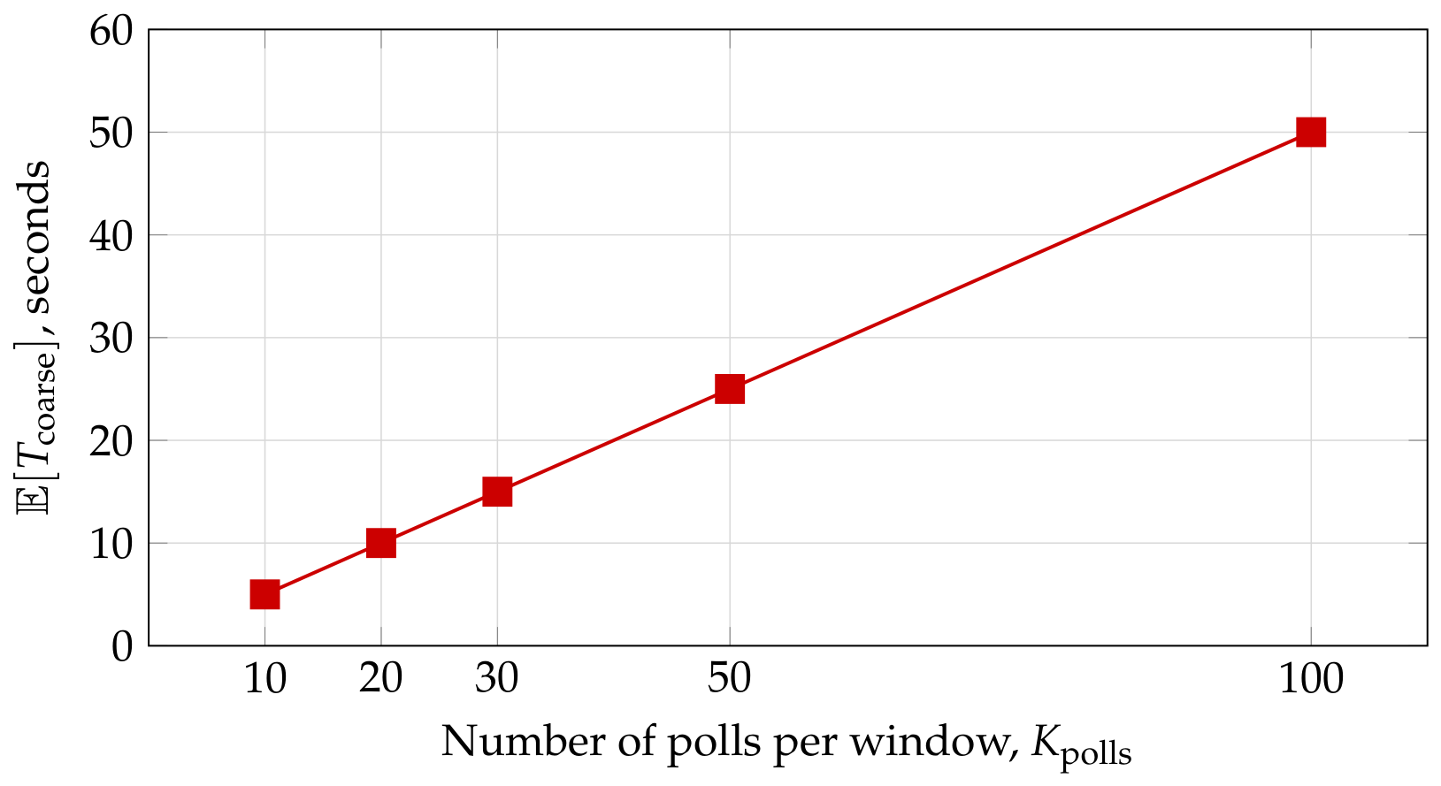
It is important to distinguish between the two operating modes mentioned in Section 3. For the initial full calibration, the coarse-search time is hours. While this duration is significant, it is a one-time procedure performed during system installation. Once the approximate position of the signal window is known, the algorithm switches to the fast-search mode. For example, if the search range is reduced to windows (compared to for the full calibration scan), the coarse-search time drops to approximately 50 s. The parameters for this fast-search mode are summarized in Table 1. Figure 9 illustrates how the coarse-search time scales linearly with the number of polls per window.
Figure 9.
Mean coarse-search acquisition time as a function of the number of polls per window (for windows and ms).
Refinement-stage estimate. The refinement stage subdivides the three windows , , and into subintervals of ps. Since each window has a duration ns, each window contains 200 subintervals, giving 600 subintervals in total. For a 100 km link, approximately 100 polls per subinterval are required to reach a detection probability above (Section 5). With one poll per frame of duration ms, the refinement time is
This estimate adds to the coarse-search time of 50 s in the fast-search mode. Thus, after initial calibration, the total synchronization time for a 100 km link is approximately 110 s. While this is a one-time procedure per session, its duration determines the initial duty cycle and must be accounted for in system design. Reducing the synchronization time—for example, by parallelizing polls or by further reducing the search range—is therefore a key direction for future work.
The key contribution of this table is that, where the original analysis focused only on the probability of single-shot detection, the present model translates this quantity into a system-level parameter—the coarse-search acquisition time—which is directly relevant for engineering design. The refinement-stage estimate above shows that, for long fiber links, the total synchronization time is dominated by the refinement stage rather than by the coarse search.
6.4. Impact on MDI-QKD Performance
The total synchronization acquisition time (coarse search plus refinement) directly determines the fraction of time available for key generation. If the total operating time of the system is , and the synchronization time is , the effective duty cycle for quantum key distribution is
Charlie’s adjustment and control-message delays are not quantified in the present study and are assumed to be small compared with the coarse-search and refinement times. Their detailed treatment is left for future work.
After synchronization is completed, the system enters the key-generation phase. However, temperature drifts induce changes in the propagation delay (typically about 30 ps/(km·°C)), which necessitates periodic re-synchronization or continuous tracking. The shorter the synchronization time, the higher the tolerable drift rate.
In addition, the scanning resolution of the synchronization procedure directly affects the visibility of two-photon interference. It is known that, for pulses of 100 ps duration, the tolerable temporal shift is about ps, whereas for 200 ps pulses it is about ps. The 10 ps scanning resolution reported in this work is well below these thresholds. However, it is important to distinguish between the scanning resolution of the algorithm and the actual timing accuracy: the latter is limited by detector, source, and electronics jitter, which is not quantified in the present study. If the residual timing error after refinement remains below the tolerable shift, the critical engineering parameter becomes the synchronization speed; a detailed jitter analysis is the subject of ongoing work.
7. Discussion and Conclusions
We present an autonomous synchronization algorithm for MDI-QKD systems that provides a 10 ps scanning resolution without auxiliary channels or trusted central hardware. The method is grounded in a physically transparent statistical detection framework and is compatible with realistic fiber-network conditions.
Compared with our previous work on synchronization in autocompensating QKD systems, the present contribution introduces three new elements: the adaptation of the synchronization concept to the MDI-QKD topology with a modified station design, the probabilistic analysis of sequential signal detection with maximum-value selection, and the model of the synchronization acquisition time that includes both the coarse search and the refinement stages.
The results presented in this work are numerical and rely on several model assumptions, including Gaussian noise, ideal detector recovery, and authenticated control messages. Experimental validation of the proposed algorithm is left for future work. The synchronization procedure assumes that control messages are authenticated using a pre-shared key; without authentication, an adversary could inject false timing corrections. In addition, the untrusted node cannot access the key material, but it can delay or drop messages, which would affect the synchronization time. These limitations should be addressed in future work on secure synchronization protocols for MDI-QKD networks.
The proposed approach enhances scalability of MDI-QKD networks and reduces architectural complexity. Future work will address experimental validation and analyze security implications related to authentication during the synchronization phase.
Author Contributions
Conceptualization, A.P.; Methodology, A.P.; Validation, A.S.; Formal analysis, A.S.; Investigation, A.P.; Data curation, A.S.; Writing—original draft, A.P.; Supervision, A.S.; Project administration, A.S.; Funding acquisition, A.P. All authors have read and agreed to the published version of the manuscript.
Funding
This research was funded by Russian Science Foundation, grant number 25-29-00007.
Data Availability Statement
The original contributions presented in this study are included in the article. Further inquiries can be directed to the corresponding author.
Acknowledgments
This work was supported by the Russian Science Foundation under Grant No. 25-29-00007.
Conflicts of Interest
The authors declare no conflicts of interest.
References
- Shor, P.W.; Preskill, J. Simple proof of security of the BB84 quantum key distribution protocol. Phys. Rev. Lett. 2000, 85, 441–444. [Google Scholar] [CrossRef] [Scilit] [PubMed]
- Bennett, C.H.; Brassard, G. Quantum cryptography: Public key distribution and coin tossing. In Proceedings of the IEEE International Conference on Computers, Systems and Signal Processing, Bangalore, India, 9–12 December 1984; pp. 175–179. [Google Scholar]
- Ekert, A.K. Quantum cryptography based on Bell’s theorem. Phys. Rev. Lett. 1991, 67, 661–663. [Google Scholar] [CrossRef] [Scilit] [PubMed]
- Kulik, S.P.; Molotkov, S.N. Quantum networks: Key distribution through untrusted nodes. Cybersecur. Issues 2025, 3, 90–98. (In Russian) [Google Scholar] [CrossRef] [Scilit]
- Lo, H.K.; Curty, M.; Qi, B. Measurement-Device-Independent Quantum Key Distribution. Phys. Rev. Lett. 2012, 108, 130503. [Google Scholar] [CrossRef] [Scilit] [PubMed]
- Tan, H.; Gu, S.; Zhu, H.; Shen, J.; Bhuiyan, Z.A.; Wu, Q.M.J. An Efficient ASCON-Based Group Authentication and Key Agreement Scheme With Non-Linkability and Integrity Assurance for IIoTs. IEEE Trans. Dependable Secur. Comput. 2026, 23, 8032–8047. [Google Scholar] [CrossRef] [Scilit]
- Sourav; Ali, R.; Obaidat, M.S. Lattice-based Certificateless Signcryption Scheme using Blockchain for Smart Healthcare Systems. IEEE Trans. Emerg. Top. Comput. 2026, 1–12. [Google Scholar] [CrossRef] [Scilit]
- Ponosova, I.; Zhluktova, D.; Ruzhitskaya, D.; Trefilov, A.; Huang, A.; Wolf, V.; Kamynin, V.; Tsvetkov, V.; Makarov, V. Pulsed laser attack at 1061 nm potentially compromises quantum key distribution. Appl. Phys. Lett. 2025, 127, 194002. [Google Scholar] [CrossRef] [Scilit]
- Briegel, H.J.; Dür, W.; Cirac, J.I.; Zoller, P. Quantum Repeaters: The Role of Imperfect Local Operations in Quantum Communication. Phys. Rev. Lett. 1998, 81, 5932–5935. [Google Scholar] [CrossRef] [Scilit]
- Kimble, H.J. The Quantum Internet. Nature 2008, 453, 1023–1030. [Google Scholar] [CrossRef] [Scilit] [PubMed]
- Wehner, S.; Elkouss, D.; Hanson, R. Quantum Internet: A Vision for the Road Ahead. Science 2018, 362, eaam9288. [Google Scholar] [CrossRef] [Scilit] [PubMed]
- Xu, F.; Qi, B.; Lo, H.K. Experimental Measurement-Device-Independent Quantum Key Distribution. Phys. Rev. Lett. 2013, 111, 130502. [Google Scholar] [CrossRef] [Scilit] [PubMed]
- Marcandelli, P.; Mariani, S.; Siena, M.; Markidis, S. Continuous-Variable Quantum Fourier Layer: Applications to Filtering and PDE Solving. Algorithms 2026, 19, 370. [Google Scholar] [CrossRef] [Scilit]
- Jayasinghe, U.; Samarathunga, P.; Fernando, T.; Fernando, A. Transmit and Receive Diversity in MIMO Quantum Communication for High-Fidelity Video Transmission. Algorithms 2025, 18, 436. [Google Scholar] [CrossRef] [Scilit]
- Jayasinghe, U.; Fernando, T.; Fernando, A. High-Fidelity Image Transmission in Quantum Communication with Frequency Domain Multi-Qubit Techniques. Algorithms 2025, 18, 501. [Google Scholar] [CrossRef] [Scilit]
- Tang, Y.L.; Yin, H.L.; Chen, S.J.; Liu, Y.; Zhang, W.J.; Jiang, X.; Zhang, L.; Wang, J.; You, L.X.; Guan, J.Y.; et al. Field test of measurement-device-independent quantum key distribution. IEEE Photonics J. 2015, 21, 116–122. [Google Scholar] [CrossRef] [Scilit]
- Comandar, L.C.; Fröhlich, B.; Dynes, J.F.; Sharpe, A.W.; Yuan, Z.L.; Penty, R.V.; Shields, A.J. Measurement-device-independent quantum key distribution with polarized photons. Opt. Express 2015, 23, 20521–20533. [Google Scholar] [CrossRef] [Scilit] [PubMed]
- Yin, H.L.; Chen, T.Y.; Yu, Z.W.; Liu, H.; You, L.X.; Zhou, Y.H.; Chen, S.J.; Mao, Y.; Huang, M.Q.; Zhang, W.J.; et al. Measurement-Device-Independent Quantum Key Distribution over 404 km of Optical Fiber. Phys. Rev. Lett. 2016, 117, 190501. [Google Scholar] [CrossRef] [Scilit] [PubMed]
- Cao, Z. Discrete-phase-randomized measurement-device-independent quantum key distribution. Phys. Rev. A 2020, 101, 062325. [Google Scholar] [CrossRef] [Scilit]
- Lai, S.E.; Cheng, C.H.; Matsumoto, A.; Akahane, K.; Lin, G.R. Security-Enhanced Differential Binary-Phase-Shift-Keying Quantum Key Distribution With a Wavelength-Switchable Single-Photon Carrier. Adv. Photonics Res. 2026, 7, e202500327. [Google Scholar] [CrossRef] [Scilit]
- Cao, Y.; Zhao, Y.; Wu, Y.; Yu, X.; Zhang, J. Time-Scheduled Quantum Key Distribution (QKD) Over WDM Networks. J. Light. Technol. 2018, 36, 3382–3395. [Google Scholar] [CrossRef] [Scilit]
- Long, N.K.; Malaney, R.; Grant, K.J. A Survey of Machine Learning Assisted Continuous-Variable Quantum Key Distribution. Information 2023, 14, 553. [Google Scholar] [CrossRef] [Scilit]
- Rodriguez, A.; Martinez, J.; Garcia, M. Adaptive synchronization using neural networks for long-distance MDI QKD. Opt. Express 2024, 32, 4567–4582. [Google Scholar] [CrossRef]
- Valencia, A.; Scarcelli, G.; Shih, Y. Distant clock synchronization using entangled photon pairs. Appl. Phys. Lett. 2004, 85, 2655–2657. [Google Scholar] [CrossRef] [Scilit]
- Cochran, R.; Gauthier, D. Qubit-based clock synchronization for QKD systems using a Bayesian approach. Entropy 2021, 23, 988. [Google Scholar] [CrossRef] [Scilit] [PubMed]
- Makarov, V.A.; Laidsalu, A.V.; Saarepere, S.M.; Eiver, R.E. System and Method for Compensating for Time Shift of Optical Pulses in Quantum Channels of Quantum Key Distribution Device with Untrusted Central Node. RU Patent No. 2840296, 21 May 2025. (In Russian) [Google Scholar]
- Makarov, V.A.; Laidsalu, A.V.; Saarepere, S.M.; Eiver, R.E. Quantum Key Distribution System with Untrusted Central Node and Method of Preparing Quantum States for Quantum Key Distribution Protocol with Untrusted Central Node. RU Patent No. 2834620, 11 February 2025. (In Russian) [Google Scholar]
- Makarov, V.A.; Laidsalu, A.V.; Saarepere, S.M.; Eiver, R.E. Synchronization Device for Quantum Key Distribution Systems at Side Frequencies in Star Topology. RU Patent No. 2834882, 17 February 2025. (In Russian) [Google Scholar]
- Rudavin, N.V.; Gerasin, I.S.; Mekhtiev, E.E.; Duplinsky, A.V.; Kurochkin, Y.V. Synchronization protocol for MDI-QKD systems. Sci. Tech. Bull. Peter Gt. St. Petersburg Polytech. Univ. Phys. Math. Sci. 2022, 15, 56–60. (In Russian) [Google Scholar]
- Pljonkin, A.; Rumyantsev, K.; Singh, P.K. Synchronization in quantum key distribution systems. Cryptography 2017, 1, 18. [Google Scholar] [CrossRef] [Scilit]
- Galliardi, R.M.; Karp, S. Optical Communication; Svyaz’: Moscow, Russia, 1978. (In Russian) [Google Scholar]
- Pljonkin, A.P. Experimental synchronization of quantum communication system. Rep. Tomsk State Univ. Control Syst. Radioelectron. 2024, 27, 37–41. [Google Scholar] [CrossRef] [Scilit]
- Gao, W.; Venkatesan, R.; Li, C. A pulse shape design method for ultra-wideband communications. In Proceedings of the 2007 IEEE Wireless Communications and Networking Conference; IEEE: Piscataway, NJ, USA, 2007; pp. 2800–2805. [Google Scholar] [CrossRef] [Scilit]

Disclaimer/Publisher’s Note: The statements, opinions and data contained in all publications are solely those of the individual author(s) and contributor(s) and not of MDPI and/or the editor(s). MDPI and/or the editor(s) disclaim responsibility for any injury to people or property resulting from any ideas, methods, instructions or products referred to in the content. |
© 2026 by the authors. Licensee MDPI, Basel, Switzerland. This article is an open access article distributed under the terms and conditions of the Creative Commons Attribution (CC BY) license.