


Abstract
The hydrophilicity of the porous transport layer (PTL) critically influences the mass transport overpotential and overall efficiency of a proton exchange membrane water electrolyzer (PEMWE). In this study, titanium felts with three distinct levels of hydrophilicity are systematically characterized and evaluated electrochemically. A novel bilayer gradient hydrophilic titanium felt structure is designed, resulting in notable performance improvements: the average cell voltage decreases by 12.92%, and the overpotential is reduced by 9.94–18.03% across a current density range of 0.1–1.6 A·cm−2. High-speed imaging reveals that the gradient hydrophilic structure effectively regulates bubble dynamics, nearly eliminating annular flow bubbles, reducing the proportion of slug flow bubbles by 40.78%, decreasing the bubble detachment diameter by 28.26%, and enhancing bubble displacement by 51.03% compared to that of untreated titanium felt. These results demonstrate that gradient hydrophilic structures can significantly enhance PEMWE performance, offering a promising strategy and a theoretical foundation for optimizing mass transfer in electrolytic systems.
1. Introduction
Hydrogen holds great promise as a clean fuel, storing 2–3 times more energy per unit mass than fossil fuels [1]. Its low density enables rapid diffusion in air, contributing to efficient combustion [2]. Among various hydrogen production methods, proton exchange membrane water electrolysis (PEMWE) has garnered significant interest due to its high current density, rapid response, ability to directly produce high-purity hydrogen (>99.99%) without extensive downstream purification [3] and excellent dynamic performance. These attributes make PEMWE particularly suitable for integration with fluctuating renewable energy sources, offering distinct advantages over alkaline and solid oxide electrolysis technologies in terms of operational flexibility. While alkaline electrolyzers can also accommodate variable power input, their response speed, startup/shutdown frequency, and lower operational load range are more limited [4]. In contrast, PEMWE exhibits a wider and more responsive dynamic operating window (e.g., 10–150% load), enabling better adaptation to rapid, second- or minute-level fluctuations in renewable generation [5]. However, the further development of PEMWE faces three primary challenges: (i) high cost, primarily from the use of precious metal catalysts; (ii) the need for optimized structural designs; and (iii) the need for a deeper understanding and tailoring of material properties. The latter two are closely linked to bubble management, a key strategy for improving reaction efficiency by promoting rapid bubble removal. Flow channel designs, such as parallel [6], serpentine [7] and biomimetic channels, have been extensively studied, and selecting an appropriate flow channel is critical to enhancing PEMWE performance. Surface structural modifications also represent an effective improvement measure, to modify the wettability of the porous transport layer PTL [8,9], some researchers have achieved better bubble management performance by adjusting the pore size [10,11], thickness and porosity [12] of the PTL. Modifications of these parameters can lead to improved bubble management. However, they often involve trade-offs with other factors such as mass transport resistance and electrical contact.
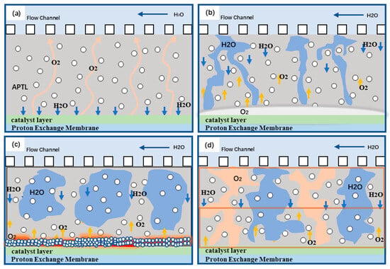
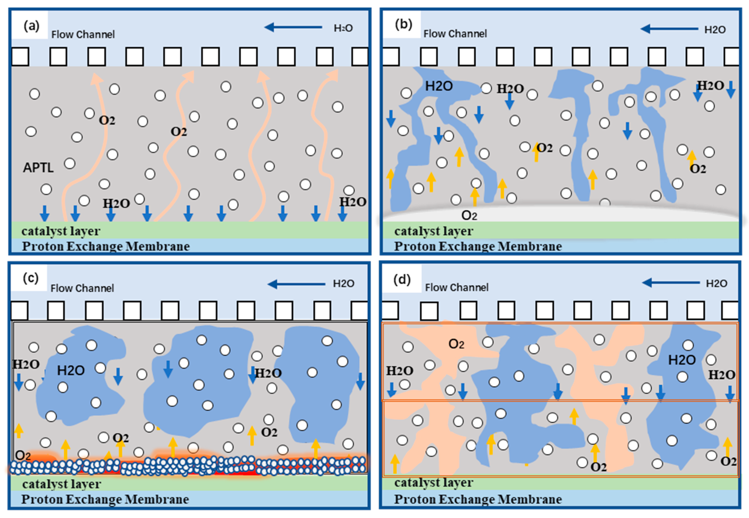
The anodic porous transport layer (APTL), as a critical component connecting the anode catalyst layer (ACL) and the anode flow channel in PEMWE, plays an essential role in the oxygen evolution reaction (OER) at the anode. Oxygen is generated in the ACL, counter to the flow of liquid water, and then transported through the APTL toward the flow channels, as illustrated in Figure 1a, and is eventually discharged from the PEMWE system together with unreacted water [13]. At high current densities, oxygen bubbles are produced at a very high rate and tend to form an oxygen film between the APTL and ACL [14]. In addition, oxygen bubbles are prone to accumulate within the internal pores of the APTL or at the interface between the APTL and the liquid water in the flow channels, making them difficult to diffuse and detach. Such phenomena hinder water supply and oxygen bubble removal, thereby increasing mass transport losses at the anode side of PEMWE, as shown in Figure 1b.
Figure 1.
(a) Gas–liquid flow schematic(Blue arrows represent water, and yellow arrows represent oxygen); (b) untreated Ti felt flow; (c) hydrophilic-treated Ti felt flow; (d) bilayer Ti felt flow (hydrophilic top/untreated base).
To enhance PEMWE performance, H. Ito et al. reported that electrolysis performance was improved with decreasing PTL pore size, which influenced the flow regime and water supply [13]. Carl Cesar Weber observed that reducing the PTL thickness from 2 mm to 0.5 mm led to a 50 mV decrease in overpotential at 4 A·cm−2 [15]. Lin Rui demonstrated that higher porosity facilitated oxygen removal; however, increased porosity also enlarges the bubble detachment volume, making it more likely to form segmented blockage flow. Furthermore, increased porosity reduced the contact area between the PTL and the catalyst layer [16]. Kaito’s experiments revealed that the cell voltage increased with the hydrophobicity of the PTL, whereas hydrophilic treatment resulted in smaller transported bubbles and more observable bubble pathways [17]. Although considerable research had been conducted on wettability-related modifications, most efforts had focused on treating single-layer diffusion layers, while neglecting the actual operating conditions of the wetted surface. This often increased mass transfer resistance and caused losses in the anodic reaction zone, as shown in Figure 1c. Although hydrophilic treatment of titanium felt could supply sufficient liquid water, the hydrophilic surface tended to trap small bubbles within the pores, thus increasing gas diffusion resistance [18] and leading to local overheating or higher cell voltage. Studies had shown that excessive oxygen bubble coverage on the ACL surface could raise the cell voltage and reduce efficiency, thereby deteriorating the overall performance of the electrolyzer [19]. Moreover, modifying only a single diffusion layer’s wettability typically improved either gas or liquid transport in one direction, but often proves insufficient to simultaneously optimize both gas and liquid transport, which is essential for efficient two-phase flow.
To address this issue, this study investigates the different operating conditions at the APTL–ACL and APTL–anode flow channel interfaces by employing a bilayer diffusion layer design with corresponding wettability, and compares its performance with that of the conventional single-layer diffusion layer. As illustrated in Figure 1d, a bilayer titanium felt is used, where the hydrophilic titanium felt near the flow channel ensures adequate liquid water supply, while the untreated titanium felt near the catalyst layer prevents gas accumulation caused by water blockage and maintains better contact with the ACL. In this work, bubble behavior was observed using a high-speed camera and a transparent electrolyzer, while physical characterization and electrochemical experiments were conducted to compare performance. This study aims to elucidate the specific effects of the gradient wettability of the bilayer titanium felt on PEMWE performance and to further provide a new perspective for the development of PTL.
2. Experimental Methods and Characterization
2.1. Visualized PEMWE System
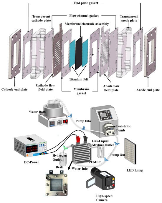
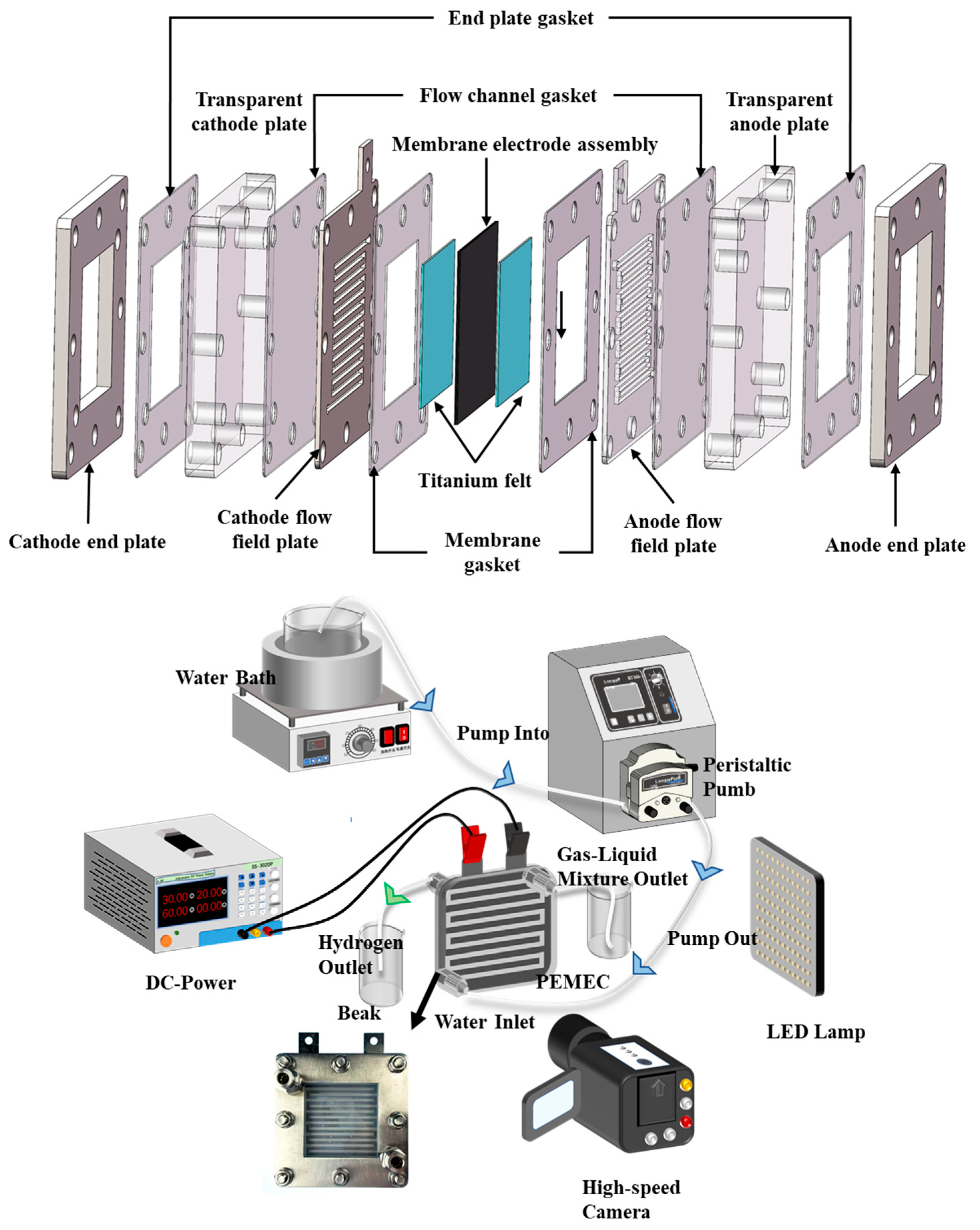
The experimental setup was established to comprehensively evaluate the performance of PEMWE. Therefore, the study employed a visualized electrolyzer approach and implemented specific modifications to the conventional PEMWE structure. As shown in Figure 2, the flow channel is a serpentine channel with an area of 50 mm × 50 mm. The diffusion layer is a commercial fibrous sintered titanium felt. The titanium felt (Shangte New Materials Co., Ltd., Weifang, China) was made of industrial pure titanium TA1, with a pore size of 15 μm. The porosity of the titanium felt is maintained at a relatively high level of 60–65%. Its thickness is selected as 0.6 mm. The proton exchange membrane is a Nafion 117 membrane sourced from Dongguan Hydrogen New Energy Co., Ltd., Dongguan, China, which is the standard CCM structure. The anode catalyst loading is 1.0 mg·cm−2 of IrO2, and the cathode catalyst loading is 0.5 mg·cm−2 of Pt/C. The flow channel plate is made of stainless steel with a thickness of 2 mm. The end plates are made of transparent acrylic to allow better observation of bubble dynamics under good light transmittance. The entire electrolyzer is fixed by eight uniformly distributed bolts. These bolts are assembled diagonally and sequentially tightened, initially to a torque of 2.0 N·m for preliminary fixation, followed by a final torque of 3.5 N·m [20]. The experimental system includes the visualized electrolyzer, power supply, peristaltic pump, thermostatic water bath and high-speed camera. The thermostatic water bath is a DF-101S collector-type constant temperature heating magnetic stirrer (Yu Hua Instrument Co., Shanghai, China), which continuously supplies temperature-controlled deionized water to the electrolyzer. The power supply is a SS-3050P (ABF Electronic Co., Shenzhen, China) programmable DC regulated power supply with a voltage range of 0–30 V, a maximum current output of 50 A, and an error control within 0.01%. The peristaltic pump is a BT300-1F (Langer Precision Pump Co., Ltd., Baoding, China) equipped with a YZ151 5x pump head. The dedicated tubing has an inner diameter of 1.6 mm and an outer diameter of 4.8 mm, providing a maximum flow rate of 75 mL·min−1.
Figure 2.
Visualized PEMWE and system.
2.2. Wettability Modification of PTL
Hydrophilic treatment was performed using the silane coupling agent KH550. KH550 is not merely physically adsorbed but forms a covalent Ti–O–Si bond via the condensation of silanol (-Si–OH) with the titanium hydroxyl groups (Ti–OH) present on the surface of the titanium felt [21]. It acts as an “active transition layer” on the metal surface, creating a dense organic film (composed of C, N, O, Si), which subsequently provides anchoring sites for the top layer of functional materials (e.g., TiO2). This structural arrangement is key to improving coating adhesion and surface roughness. The amino group (-NH2) in KH550 introduces hydrophilic polar groups on the surface. The synergy between the KH550 interlayer and the top TiO2 layer, as demonstrated by the super-hydrophilic coating (WCA < 5°) in the cited paper [22], allows the composite surface to achieve excellent hydrophilicity. First, the titanium felt was ultrasonically cleaned in ethanol for 15 min to remove surface contaminants and oils, followed by ultrasonic cleaning in deionized water for 10 min. It was then dried in an oven at 60 °C for 60 min. The silane coupling agent KH550 was added at a specific ratio to a mixed solvent of deionized water and ethanol (10:90) and stirred for 20 min to ensure complete hydrolysis of the KH550. The titanium felt was subjected to surface hydrophilic modification via a dip-coating and curing process. Specifically, the titanium felt sample was first completely immersed in a silane coupling agent solution for 20 min, followed by 3 min of ultrasonication to enhance interfacial interactions. The sample was then withdrawn at a controlled rate of 0.5 mm/s and transferred to a constant-temperature drying oven at 60 °C for 30 min of pre-treatment. Finally, thermal curing was performed at 120 °C for 1 h to complete the hydrophilic modification of the titanium felt surface. The experimental conditions of titanium felt samples in this work are shown in Table 1.
Table 1.
Titanium Felt Sample Types and Treatment Conditions.
2.3. Characterization Methods
2.3.1. Contact Angle Goniometer
The droplet angle measurement method is one of the most commonly used techniques for determining contact angles. This method involves dispensing deionized water droplets onto the titanium felt surface using an automated injection system. A LED light source projects the droplet formed on the titanium felt onto a screen, where the angle between the tangent line and the interface is measured, directly providing the contact angle of the titanium felt surface. Additionally, since fibrous titanium felt generally exhibits hydrophilic characteristics, and the wettability modification further enhances its hydrophilicity, water droplets tend to penetrate the surface more rapidly. Therefore, when measuring the contact angle of titanium felt, the droplet was allowed to reach equilibrium with the titanium felt surface, at which point the stable image was captured and selected as the basis for measurement. To ensure data reliability, each set of experiments was repeated five times, and the average value was calculated. The single measurement result closest to the average was ultimately selected as the representative data for the contact angle of the titanium felt surface.
2.3.2. Camera System
To better capture oxygen bubbles generated by PEMWE, a high-speed camera MIRO M310 (Phantom) (Vision Research, Inc., Wayne, NJ, USA) was employed. This camera is capable of shooting at several thousand frames per second (fps) even at relatively low resolution, and is equipped with a high-resolution sensor to maintain clear image quality. It is well suited for capturing rapid bubble motion and transient bubble formation phenomena. The camera connects to a computer via a high-speed data interface and is controlled using Phantom Camera Control software (Version 3.8) for recording and playback settings. A high-optical-performance Tokina AT-X Pro Macro (Kenko Tokina Co., Ltd., Tokyo, Japan) 100 mm f/2.8 D lens was used. Each zoom lens recording was set to a field of view of 5 mm × 4 mm with a capture resolution of 1280 × 800 pixels. Upon triggering, the frame count was 8300. For measurements of bubble nucleation sites and bubble displacement velocity, a sampling frequency of 2000 fps was used, while a frame rate of 1000 fps was employed to study bubble flow patterns under steady-state conditions.
2.4. Polarization and Impedance Measurements
The deionized water preheated to 80 °C was continuously supplied to the electrolyzer for 20 min using a peristaltic pump to ensure stable temperature inside the cell. Subsequently, the cell was connected to different testing circuits. Polarization curve data were acquired using a programmable DC power supply, with current density stepped from 0.1 A·cm−2 to 1.6 A·cm−2 in sixteen increments, each recorded for five minutes. For impedance testing, titanium felt samples (50 mm × 50 mm) were used as the working electrode and fully immersed in 0.5 M H2SO4 solution simulating actual operating conditions. A graphite rod served as the counter electrode, and an Ag/AgCl electrode suitable for acidic environments was employed as the reference electrode, forming a three-electrode system to accurately measure the electrochemical impedance spectroscopy (EIS) of the titanium felt under acidic conditions. Electrochemical impedance spectroscopy was performed using a CHI 730e electrochemical workstation (CH Instruments, Inc., Shanghai, China) at applied potentials of 1.5 V and 1.7 V. The frequency range spanned from 100 kHz to 10 mHz with a perturbation amplitude of 0.005 V. Nyquist plots were generated from the scan data.
3. Results and Discussion
3.1. Physical Characterization
3.1.1. Contact Angle Characterization
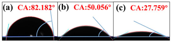
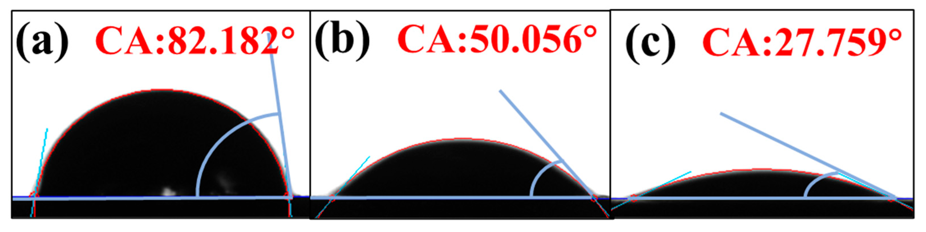
The wettability of the titanium felt surface was effectively modulated using the silane coupling agent KH550 as a hydrophilic modifier, as evidenced by the contact angle measurements presented in Figure 3a–c. The untreated T0 sample exhibited intrinsic hydrophilicity with a contact angle of 82°. Treatment with KH550 significantly enhanced this property, reducing the contact angle to 50° for T1 and further to 27° for T2. This systematic decrease confirms that the hydrophilic treatment successfully imparted the titanium felt with greater liquid adhesion. Consequently, the use of KH550 proved effective in controllably modifying the surface wettability.
Figure 3.
(a) Contact angles of T0 titanium felt; (b) contact angles of T1 titanium felt; (c) contact angles of T2 titanium felt.
3.1.2. XRD Characterization
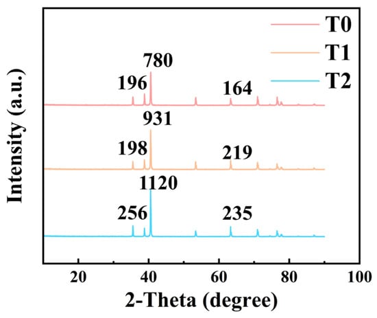
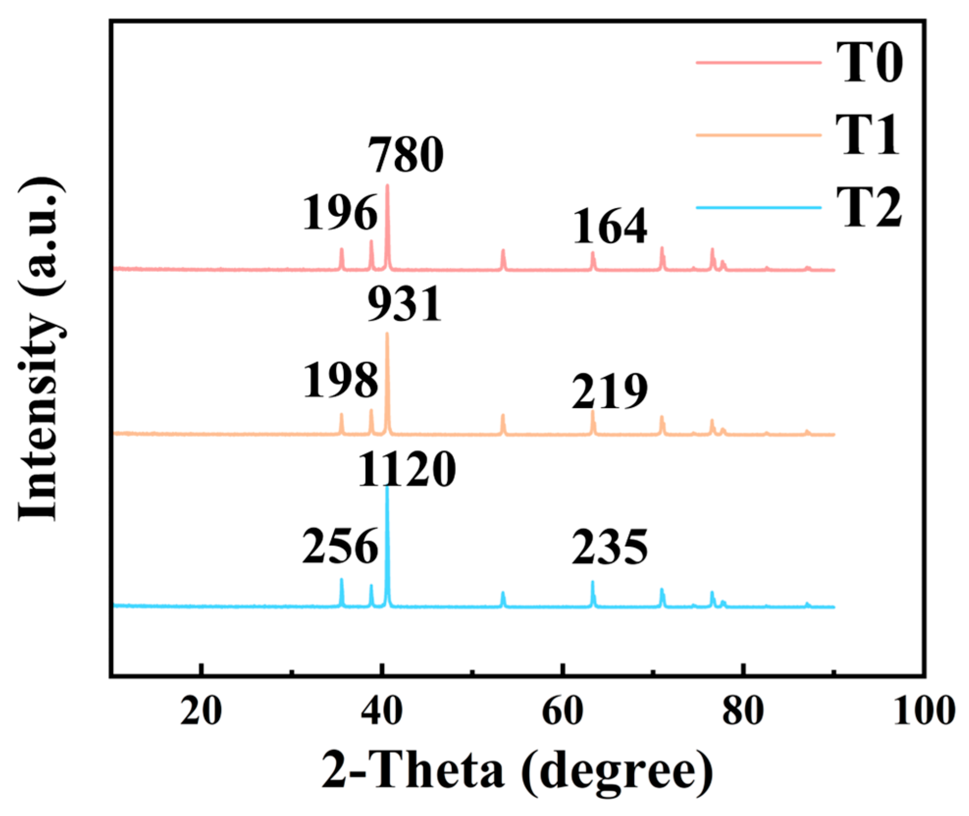
XRD analysis revealed that the structures and properties of titanium felts with varying degrees of hydrophilicity exhibit distinct differences. As shown in Figure 4, the diffraction peaks of the modified titanium felts were identical to those of the unmodified ones. The characteristic diffraction peaks at 2θ values of 35.05°, 38.63°, 41.04°, 54.56° and 70.32° correspond to the characteristic peaks of titanium [23]. No other crystalline phases were detected, indicating that the hydrophilic modification treatment did not alter the crystalline phase composition of the titanium felt.
Figure 4.
X-ray diffractograms of titanium felts with different hydrophilic degrees.
Despite unchanged phase structure, the diffraction peak intensities of modified samples (T1, T2) increase significantly relative to the unmodified sample (T0). Taking the dominant Ti (101) peak at 2θ ≈ 40.10° as an example, the peak heights are 780 a.u. (T0), 931 a.u. (T1) and 1120 a.u. (T2), respectively. Similarly, the intensity of the peak at 2θ ≈ 65° rises from 164 a.u. (T0) to 219 a.u. (T1) and 235 a.u. (T2). This enhancement is attributed to optimized surface microstructure during modification: the pristine Ti felt (T0) possesses a native amorphous oxide layer, organic contaminants and surface defects that attenuate diffraction signals; the modification process removes these disordered layers via cleaning and activation, while slightly improving the crystallinity and order of surface grains, thereby reducing X-ray scattering and enhancing diffraction intensity.
Notably, the incremental increase in peak intensity correlates well with the gradual improvement in surface hydrophilicity (T0 < T1 < T2). Enhanced surface crystallinity exposes more polar Ti–O and Ti–OH sites, strengthening hydrogen bonding interactions with water molecules and thus improving wettability. The synchronous changes in diffraction intensity and hydrophilicity provide direct structural evidence for the effectiveness of the hydrophilic modification strategy, establishing a positive correlation between surface crystalline order and wetting performance.
3.1.3. SEM Characterization
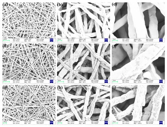
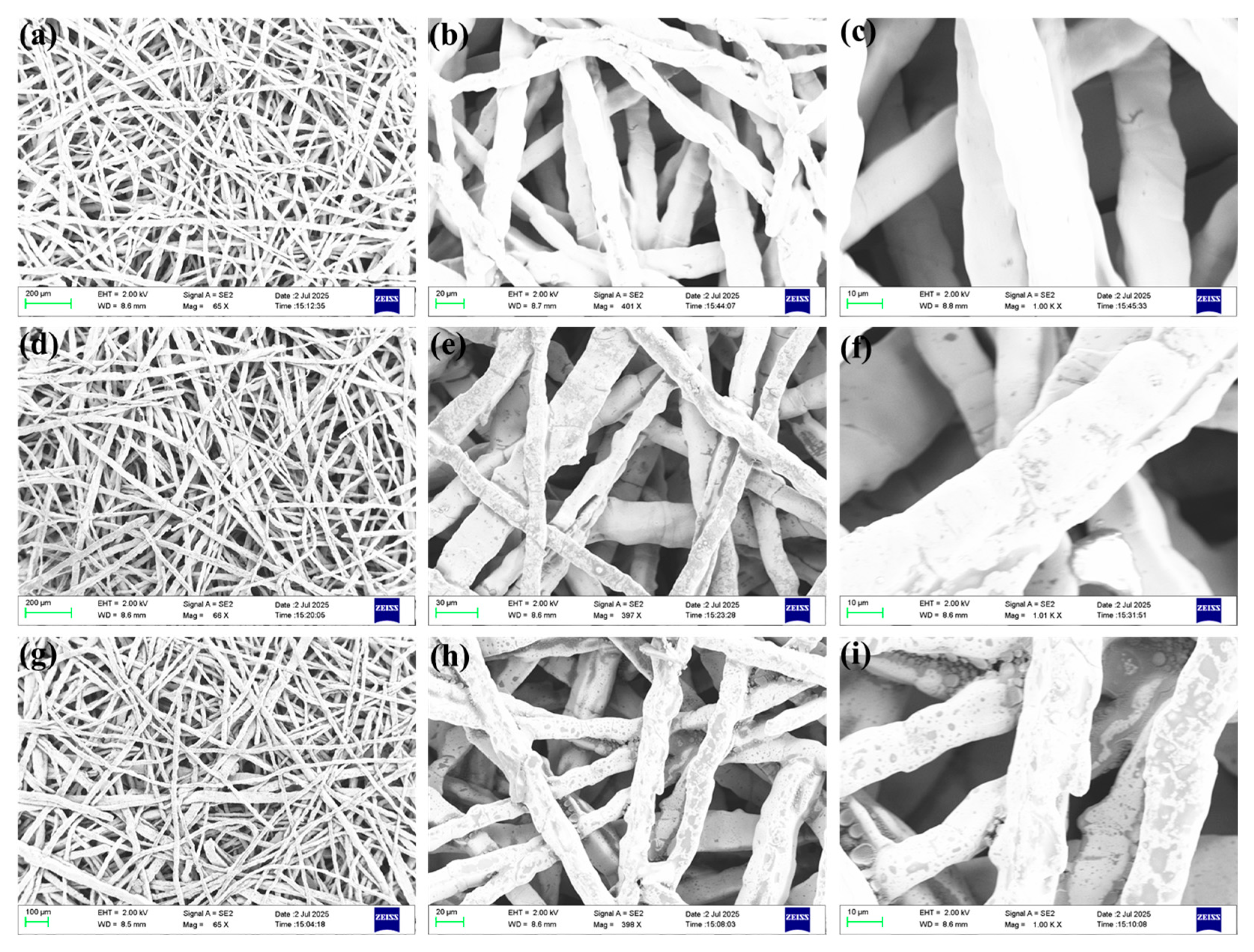
The titanium felt morphologies were characterized by scanning electron microscopy (SEM) (ZEISS, SUPRA 55, Oberkochen, Germany). As shown in Figure 5, we could find distinct differences among the three titanium felts at 65× magnification: the untreated titanium felt (Figure 5a) exhibited a smooth surface, which clearly reflected the metallic bulk texture, whereas the titanium felts treated with the silane coupling agent KH550 (Figure 5d,g) showed a significantly darker overall coloration. Observations at 400× magnification indicated that this color difference arises from a dense hydrophilic coating layer formed on the fibers of the titanium felts (Figure 5e,h), contrasting with the smooth surface of the untreated felt (Figure 5b,c).
Figure 5.
SEM images of (a–c) T0, (d–f) T1, and (g–i) T2 titanium felts at different magnifications (left to right: 65×, 400×, 1000×).
Notably, the degree of hydrophilic modification correlated positively with surface roughness—the micro-nanoscale protrusions generated during the KH550 curing process not only enhanced hydrophilicity but also confirmed effective interfacial bonding. At 1000× magnification, T2 titanium felt exhibited more pronounced features: in addition to the coating on the fiber surfaces, numerous droplet-shaped hydrophilic agent deposits cured at high temperature were distributed within the fiber gaps (Figure 5f,i), providing a structural basis for its superior hydrophilicity.
3.2. Electrochemical Characterization
3.2.1. PEMWE Polarization Curves of Single-Layer Titanium Felt
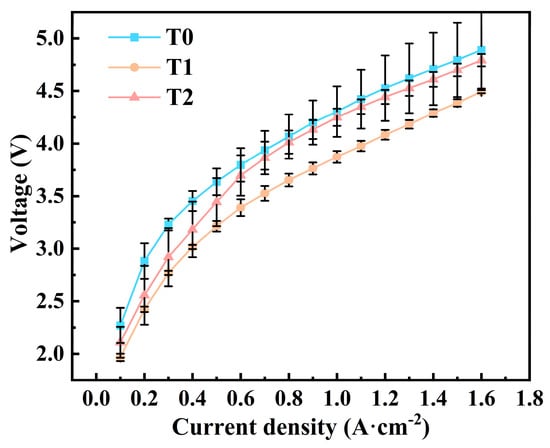
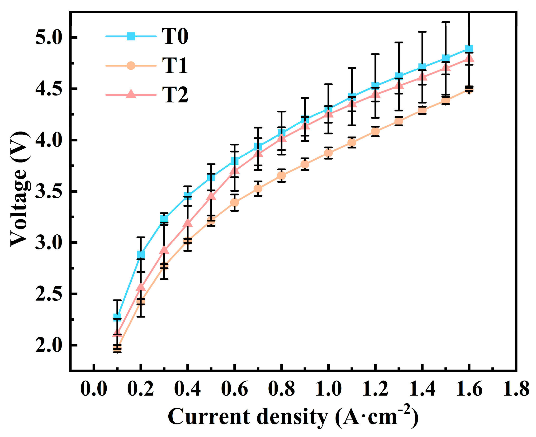
Figure 6 showed the polarization curve of the three cells with the three types of single-layer titanium felts, where data points represent mean values from three experimental replicates with error bars indicating standard deviation. We could find that the hydrophilically treated T1 titanium felt exhibited significantly improved electrochemical performance. Its average polarization potential was 3.56 V, representing a 10.55% reduction compared with that of the untreated T0 titanium felt (3.98 V). Moreover, in the current density range of 1.0–1.6 A·cm−2, the voltage of T1 titanium felt remained 9.24% lower than that of the T0 sample. Furthermore, T1 titanium felt demonstrated a more stable overpotential response during dynamic current scanning, with an overpotential increase of 2.53 V and a 3.56% reduction in potential fluctuation amplitude relative to the T0 sample. T2 titanium felt showed performance comparable to T0 in the high current density region, with no significant optimization effect; all groups exhibited similar growth trends. However, T2 still showed some performance improvement, with an average polarization potential decreased by 3.27% compared with T0. T1 titanium felt successfully shifted the overall polarization curve to a lower overpotential region, significantly reduced electrolyzer energy consumption and made it particularly suitable for high-load applications. Mechanistic analysis of the electrochemical performance differences suggested that oxygen bubble dynamics were a key factor influencing PEMWE performance. First, increased hydrophilicity promoted rapid oxygen bubble detachment on the titanium felt surface, by increasing nucleation site density to enhance gas transport efficiency and by reducing bubble size and residence time to optimize gas–liquid two-phase flow [17]. Second, oxygen bubble transport within the titanium felt was primarily governed by capillary forces [24]. According to the Young–Laplace equation, a reduction in contact angle significantly strengthened capillary forces. This change in interfacial tension promoted liquid water filling the pores, which physically squeezed bubbles to accelerate their coalescence and discharge. Finally, the oxygen evolution reaction (OER) mainly occurred at the three-phase interface among the diffusion layer, catalyst layer, and liquid water. Thus, catalyst layer utilization, liquid water supply and oxygen bubble removal determined OER efficiency. SEM images revealed that the surface structure of hydrophilic-treated titanium felt became rougher with increasing treatment intensity. This led to a decrease in anode catalyst layer utilization and an increase in local mass transport resistance, causing PEMWE performance degradation due to reduced contact area [25]. Comparing the polarization data of T1 and T2 titanium felts, although T2 treated with 3% KH550 silane coupling agent exhibited greatly enhanced surface hydrophilicity, extensive liquid water existed within the felt and between the felt and catalyst layer, thus hindering oxygen bubble removal. Additionally, T2 surface roughness is higher than that of T1, which adversely affects catalyst layer utilization.
Figure 6.
PEMWE polarization curves of single-layer titanium felt.
3.2.2. Electrochemical Impedance Spectroscopy (EIS) Study
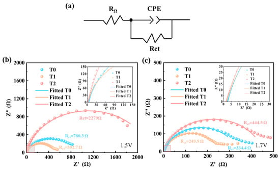
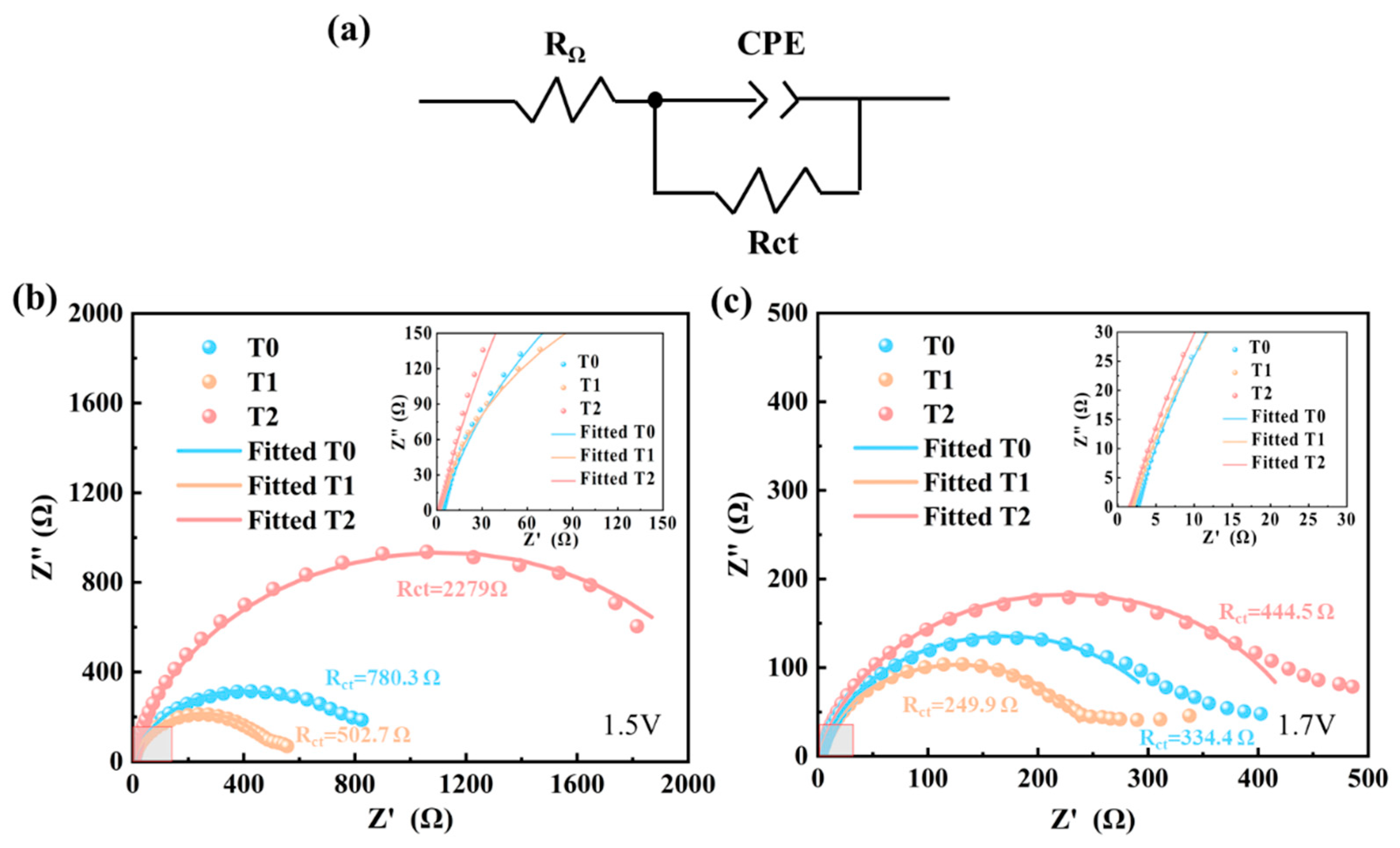
Figure 7b and Figure 7c presented the typical electrochemical impedance spectra (EIS) of titanium felts with varying hydrophilicity levels (T0, T1, and T2) measured at operating voltages of 1.5 V and 1.7 V, respectively. The corresponding Nyquist plots exhibited an approximately semi-circular feature, indicating that the charge transfer process dominates the overall impedance. This high-frequency semi-circle is closely associated with the oxygen evolution reaction occurring on the surface of the titanium felt. Under the experimental conditions of this study, when a titanium felt working electrode was immersed in a 0.5 M H2SO4 solution and subjected to anodic polarization, the oxygen evolution reaction (OER) occurring on its surface follows a typical four-electron transfer mechanism, which could be expressed by the following reaction equation: 2H2O → O2 + 4H+ + 4e−. This reaction constitutes the primary origin of the high-frequency semi-circle in the impedance spectrum, corresponding to the charge transfer resistance (Rct).
Figure 7.
(a) Equivalent circuit model of PEMWE; (b) Nyquist EIS plots at 1.5 V; (c) Nyquist EIS plots at 1.7 V.
The EIS data were analyzed using Zview 2.80 software (Scribner Associates, Inc., Southern Pines, NC, USA) by fitting to an equivalent circuit model, as shown in Figure 7a. The model consists of a parallel combination of the charge transfer resistance (Rct) and a constant phase element (CPE), connected in series with the ohmic resistance (RΩ). In the high-frequency region, the intercept of the impedance spectrum with the real axis corresponds to the ohmic resistance (RΩ), which includes contributions from the electrolyte resistance, the intrinsic resistance of the titanium felt and the contact resistance at the titanium felt/electrolyte interface. The high-frequency semi-circle, in turn, is attributed to the charge transfer resistance (Rct), which is associated with the cathodic polarization process arising from the oxygen evolution reaction on the titanium felt surface.
The results indicate that, at both 1.5 V and 1.7 V, the ohmic resistance (RΩ), derived from the high-frequency intercept of the impedance spectra, was highest for the T0 titanium felt. Moreover, RΩ gradually decreases as the hydrophilicity of the titanium felt increases from T0 to T1 and T2, while remaining stable across all three samples at both applied voltages. Simultaneously, the charge transfer resistance (Rct), obtained by fitting the high-frequency semi-circle, was lowest for the T1 titanium felt (502.7 Ω at 1.5 V and 249.9 Ω at 1.7 V), suggesting that moderate hydrophobic treatment—corresponding to the T1 hydrophilicity level—effectively enhanced charge transfer and improved electrochemical activity. Rct did not vary linearly with increasing hydrophilicity. Notably, the highest Rct was observed for the T2 titanium felt, indicating that excessive hydrophilicity was detrimental to the interfacial kinetics of the oxygen evolution reaction. Overall, the T1 titanium felt exhibited the optimal interfacial electrochemical performance, demonstrating that appropriate regulation of hydrophilicity played a crucial role in enhancing oxygen reduction activity.
The ohmic resistance (RΩ) determines the baseline voltage level, while the charge transfer resistance (Rct) reflects the activation overpotential slope. Our results show a non-monotonic dependence on hydrophilicity—T1 reduces Rct to optimize kinetics, while T2 shows increased Rct despite lower RΩ. This trade-off between ohmic and charge transfer losses underpins the macroscopic polarization behavior.
3.2.3. PEMWE Polarization Curves of the Bilayer Titanium Felt
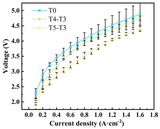
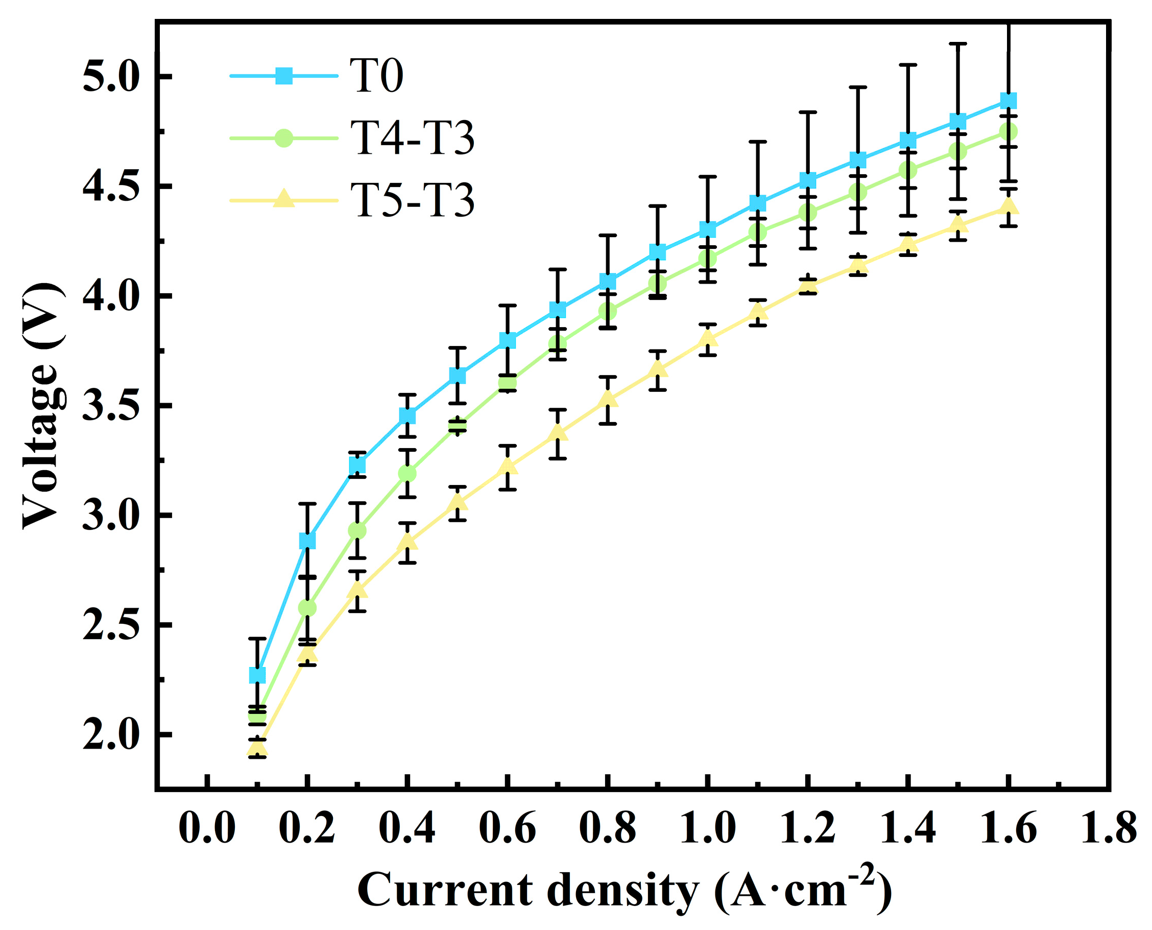
To address the issues caused by the excessive hydrophilicity and surface roughness of T2 titanium felt, a gradient wettability design was adopted: an untreated titanium felt layer was stacked beneath T2 titanium felt to balance the hydrophilic properties. To ensure structural consistency, all felts used in the stacking had a uniform thickness of 0.3 mm. As shown in Figure 8, where data points represent mean values from three experimental replicates with error bars indicating standard deviation. polarization curves showed that the bilayer titanium felts (T5-T3) exhibited superior polarization performance. The detailed polarization parameters for all tested samples are summarized in Table 2. At an initial current density of 0.1 A·cm−2, T5-T3 felt demonstrated the lowest overpotential of 1.94 V among the five groups, representing a significant reduction of 14.54% compared to that of T0 titanium felt (2.27 V). In the low-to-mid current density range (0.1–0.7 A·cm−2), T5-T3 consistently demonstrated the lowest operating voltage, registering a voltage on average 16.12% lower than that of T0, which indicated a clear performance advantage. Although the absolute advantage slightly decreases at high current densities (>1 A·cm−2), T5-T3 still outperformed the T0 group by 9.94–11.3%. Using hydrophilic titanium felt near the flow channel ensured sufficient liquid water supply to the anode catalyst layer for the oxygen evolution reaction (OER). The untreated anode fibrous titanium felt not only allowed liquid water penetration but also provided good solid surface spreading ability, increasing OER active sites and facilitating bubble nucleation. Moreover, the bubble diameters on the hydrophilic felt surface were much smaller compared to the untreated felt, allowing easier detachment from the electrode surface. Additionally, the hydrophilic felt surface could dissipate more heat generated during the reaction to some extent [26]. Using untreated titanium felt near the catalyst layer could effectively isolate the large amount of liquid water penetrating from the hydrophilic felt, avoided flooding and prevented oxygen bubble accumulation that would otherwise form an oxygen film between the catalyst layer and diffusion layer. Furthermore, T0 felt exhibited better electrical conductivity than T2, and the catalyst layer in direct contact with the smoother titanium substrate (increased conductive pathways) enlarged the contact area, effectively promoting charge transfer and improving catalyst utilization efficiency [27]. Comparing polarization curves of untreated titanium felt combined with various hydrophilic felts, the T5-T3 group performed best. At 0.1 A·cm−2, its voltage was 7.18% lower than that of the T4-T3 group (2.09 V). As current density increased to 1.6 A·cm−2, T5-T3 (4.4 V) maintained a 10.02% advantage over T0 (4.89 V) and a 7.37% advantage over T4-T3 (4.75 V). The T4-T3 group overall performed better than T0 but worse than T5-T3 in 0.1–0.7 A·cm−2; its average voltage was 7.04% lower than T0, but its advantage diminished at high current densities. T3 titanium felt was better suited for combination with T5 felt, primarily because T4 titanium felt combined with T3 felt reduced liquid water supply to the catalyst layer, resulting in an average voltage 1.2% lower than the excessively hydrophilic T2 felt. The performance loss may be primarily due to localized overheating from water shortage, the negative impact of which appears more critical than that of bubble removal issues caused by flooding [28].
Figure 8.
PEMWE polarization curves of the single-layer titanium felt (T0) and the bilayer titanium felt (T4-T3, T5-T3).
Table 2.
Polarization parameters of the single-layer titanium felt (T0) and the bilayer titanium felt (T4-T3, T5-T3).
3.3. Investigation of Bubble Behavior
3.3.1. Initial Electrolysis Bubble Detachment Diameter and Displacement Velocity
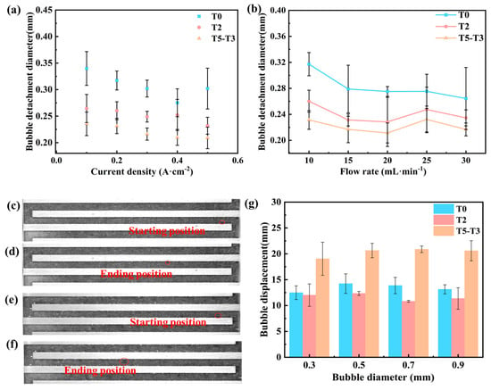
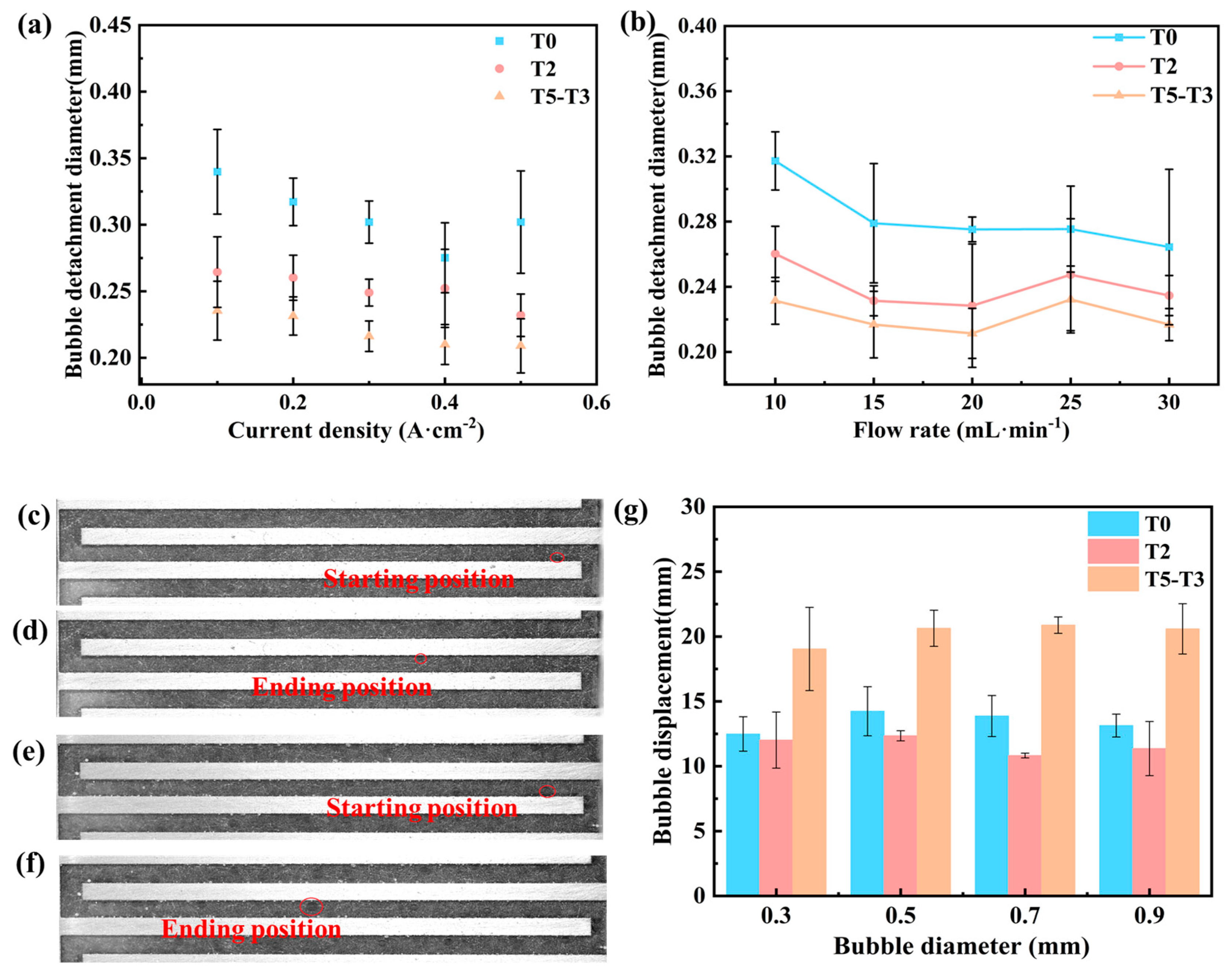
Figure 9a,b presented the variation in bubble detachment diameter with current density and flow rate for different titanium felts during electrolysis, where data points represent mean values from five experimental replicates with error bars indicating standard deviation. Supplementary Videos (S1–S3: “Bubble detachment diameter.mp4”) provided detailed temporal records of bubble detachment dynamics from the porous transport layer (PTL) surface. The bubble detachment process on hydrophilic-modified felts was completed within 0.5 ms, whereas untreated felts exhibited prolonged growth-detachment cycles, lasting up to 20 ms in some cases. This detachment delay promoted bubble coalescence during growth stages, resulting in significantly larger final detachment diameters. The mean diameter of released bubbles from untreated felts exceeded 0.3 mm, substantially larger than those from hydrophilic-modified samples.
Figure 9.
(a) Bubble detachment diameter as a function of current density for different titanium felts; (b) bubble detachment diameter as a function of flow rate for different titanium felts; (c,d) bubble displacement on the surface of T0 titanium felt; (e,f) bubble displacement on the surface of T5-T3 titanium felt; (g) bubble displacement distance on titanium felt.
The underlying mechanism involves the force balance between bubble adhesion (at the solid–gas interface) and buoyancy/drag forces. Hydrophilic surfaces reduce the gas–solid contact area while enhancing liquid–solid interaction, thereby markedly diminishing adhesion force. This enables earlier detachment at smaller bubble sizes when buoyancy overcomes the reduced adhesion.
Notably, while T2 and T5-T3 felts showed comparable detachment time, subtle differences were observed in their mean detachment diameters and nucleation site densities. Mean detachment diameters of 0.25 mm for T2 and 0.22 mm for T5-T3 demonstrate that the gradient hydrophilic treatment confers superior bubble desorption kinetics over both untreated and single-layer hydrophilic-treated PTLs.
Video evidence confirmed that rapidly detaching bubbles on hydrophilic PTLs formed continuous “pearl chain” structures that were efficiently carried away by liquid flow, contrasting sharply with the gas clogging and stagnant zones observed in untreated PTLs. This transition in flow regime substantially reduced gas transport resistance through the porous medium.
In addition, this study employed the Lagrangian method to track bubble motion, using the bubble displacement over equal time intervals as an indicator to evaluate the bubble detachment capability on the titanium felt surface. The results are shown in Figure 9c–g. Data points represent the mean values from three repeated experiments, with error bars indicating the standard deviation. Supplementary Videos (S4–S6: “PTL bubble at Initial electrolysis.mp4”) provided detailed temporal records of bubble displacement distance from the porous transport layer (PTL) surface. After observing 100 frames, the displacement of bubbles with different diameters was found to be less affected by surface treatment. Comprehensive analysis reveals that the titanium felt with gradient hydrophilic treatment exhibited the highest bubble displacement per unit time (20.28). It is noteworthy that the bubble displacement on the untreated T0 titanium felt (13.43) was higher than that of the uniformly hydrophilic-treated T2 sample (11.635). The reason lies in that although uniform hydrophilic treatment (T2) improves surface wettability, the resulting contact angle hysteresis and pinning effect on the strongly hydrophilic surface conversely suppress bubble transport. In contrast, the gradient hydrophilic structure (T5-T3) introduces a wettability gradient that generates a directional force, effectively overcoming local pinning resistance and guiding bubbles to detach efficiently along a predetermined path, thereby significantly enhancing gas transport capability. This indicates that, in the design of porous electrodes, constructing a macroscopic wettability gradient to form directional bubble escape channels is more critical than merely pursuing a uniformly hydrophilic surface.
SEM images (Figure 5f,g) reveal that the hydrophilic treatment significantly increases the surface roughness of the titanium felt fibers, introducing more defects and edge structures. These microscopic features can serve as additional bubble nucleation sites, favoring earlier and denser bubble generation, thereby promoting the formation of smaller initial bubbles. This aligns with the observation in the main text that the bubble detachment diameter is smaller on the hydrophilic PTL. XRD analysis (Figure 4) confirms the successful introduction of the hydrophilic coating. This coating chemically modifies the fiber surface, altering the solid–liquid–gas three-phase interfacial energy. Based on the Young–Laplace equation and bubble force balance analysis, the hydrophilic surface reduces the contact area between the bubble and the solid (the gas–solid interface) and enhances liquid–solid interaction, thereby significantly weakening the adhesion force (pinning effect) of bubbles on the surface. Consequently, on hydrophilically modified PTL (e.g., T2), bubbles can detach rapidly upon reaching a smaller size (within 0.5 ms as stated in the text). In contrast, on the untreated smooth surface (T0), the adhesion force is stronger, requiring bubbles to grow larger (typically exceeding 0.3 mm) before detachment, with a cycle lasting up to 20 ms.
3.3.2. Distribution of Bubble Types at Electrolysis Steady State
This study adopts the bubble type definitions proposed by Su Xin [29]: when the equivalent bubble diameter is smaller than the channel diameter, the flow pattern is defined as bubble flow. When the equivalent bubble diameter approaches the channel diameter and the bubble length along the channel is less than three times the channel diameter, the flow pattern is defined as slug flow. When the bubble length exceeds three times the channel diameter, the flow pattern is defined as annular flow.
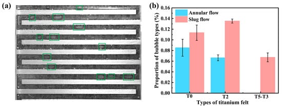
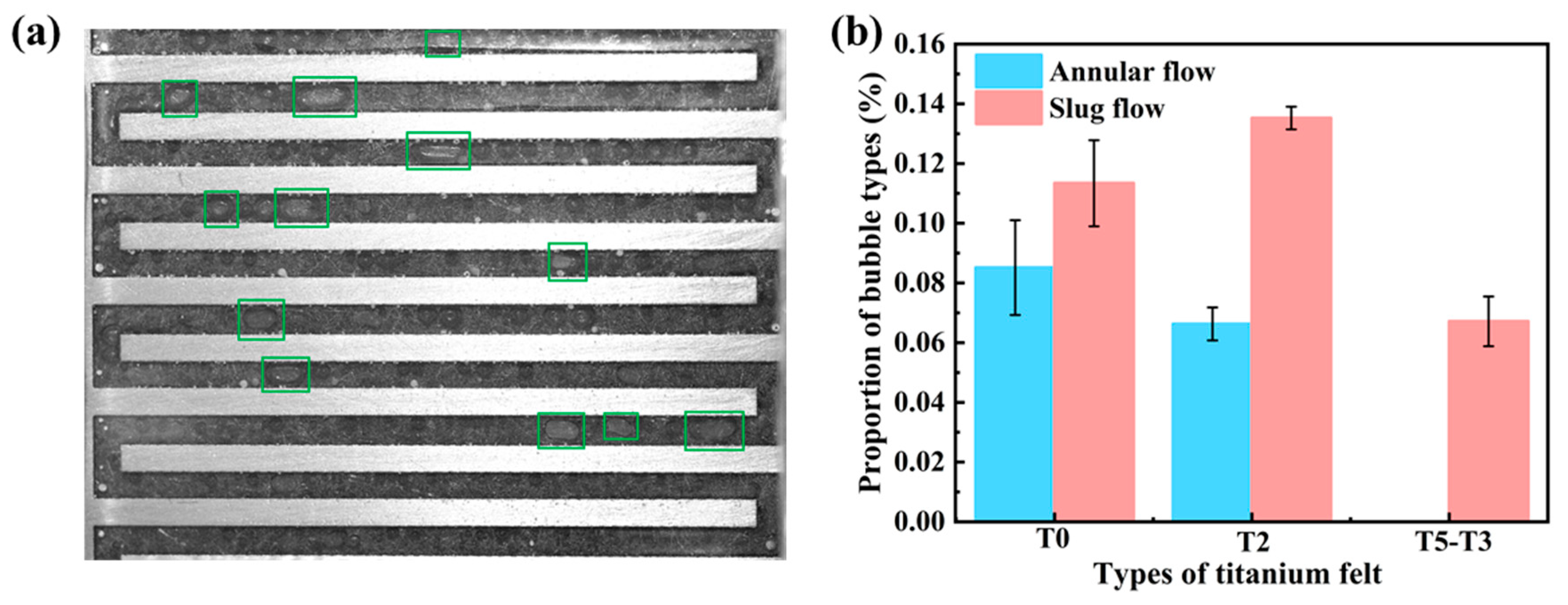
By comparing the bubble flow patterns of the three titanium felts under stable electrolysis conditions captured by the high-speed camera as shown in Figure 10, where data points represent mean values from three experimental replicates with error bars indicating standard deviation. Supplementary Videos (S7–S9: “PTL bubble types at electrolysis steady state.mp4”) provided detailed temporal records of bubble types from the porous transport layer (PTL) surface. Ιt can be seen that the bilayer titanium felt (T5-T3) exhibits no annular flow, and the number of slug flow bubbles was significantly reduced by 40.78%~50.35% compared to the other two single-layer felts. The prevalence of bubble flow, which is generally associated with more efficient mass transfer and lower flow resistance, is consistent with the superior polarization performance observed for the T5-T3 bilayer structure. In contrast, T0 titanium felt shows the highest proportion of annular flow. Under high current density, PEMWE experiences high thermal load, and annular bubbles can easily cause water deficiency and localized overheating, leading to degraded cell performance. The higher polarization values observed with T0 felt are closely related to this phenomenon. The hydrophilic-treated T2 felt shows ~19.27% reduction in slug flow compared to T0, and its performance is somewhat improved; however, the annular flow increases by 22.16%, and the overall improvement is less pronounced than that of T5-T3. This is because the hydrophilic treatment enhances the gas transport capability of the titanium felt, accelerates bubble detachment, and reduces bubble accumulation. However, the increased number of nucleation sites and the enhanced detachment efficiency also promote bubble coalescence, leading to local gas-phase accumulation. This mechanism explains why annular flow decreases while slug flow increases in T2 felt. The absence of annular flow in T5-T3 is mainly attributed to the gradient hydrophilic structure, which suppresses excess reactant supply and reduces bubble nucleation and coalescence within the pores. The reduction of annular flow lowers the two-phase flow resistance, improves the uniform distribution of liquid water in the flow channels, enhances the membrane’s wettability, reduces the formation of local hot spots and improves electrolysis efficiency. Meanwhile, the rapid bubble detachment minimizes gas accumulation on the electrode surface, optimizes the electrochemical reaction interface and enhances the hydrogen production performance and stability of PEMWE.
Figure 10.
(a) bubble types during stable electrolysis on T5-T3 titanium felt; (b) proportion of bubble types on the three titanium felts.
The behavior and flow patterns of bubbles after detachment are jointly determined by surface morphology and wettability. SEM observations indicate that the deposition of the hydrophilic agent within the fiber gaps (Figure 5h) may partially alter the local pore structure. This could be one reason why the flow pattern analysis in the main text shows that the proportion of slug flow remains relatively high in the middle section of T2. In contrast, the untreated base layer in the gradient structure (T5-T3) acts as a “buffer,” optimizing the gas–liquid distribution within the pores. As a result, annular flow is nearly eliminated, the proportion of slug flow is significantly reduced and a bubbly flow more conducive to mass transport is formed.
4. Conclusions
This study systematically investigated the mechanism by which titanium felts with different wettability (hydrophilic-treated and untreated) influence performance of a proton exchange membrane water electrolyzer, with a particular focus on how single-layer hydrophilic felts, untreated felts, and their combined bilayer structure regulate gas–liquid two-phase transport characteristics. The main conclusions are as follows:
- (1)
- The novel design of the visualized electrolyzer enabled precise capture of bubble nucleation sites and dynamic observation of bubble flow patterns within the flow channels, providing a direct experimental approach to elucidate the mechanisms of bubble-induced overpotential and mass transfer losses.
- (2)
- Dynamic bubble observations revealed that the bilayer gradient hydrophilic design optimized the interfacial wettability of the titanium felt. While the flow channel–APTL interface promoted bubble nucleation, it also suppressed bubble coalescence caused by excessive hydrophilicity, significantly reducing the occurrence of annular flow.
- (3)
- Electrochemical tests showed that the ohmic resistance of the titanium felt exhibits a nonlinear relationship with its hydrophilicity, and the bilayer titanium felt with a gradient hydrophilic design further reduces the operating voltage of the electrolyzer compared to single-layer felts.
- (4)
- The gradient hydrophilic bilayer titanium felt structure regulates surface wettability in a zoned manner: hydrophilic treatment on the flow channel side promotes reactant transport, while untreated titanium felt on the catalyst layer side ensures high catalyst layer utilization. This significantly enhances mass transfer efficiency and reduces the activation overpotential of PEMWE. By optimizing the gas–liquid two-phase transport pathways, this design achieves a synergistic improvement in electrolyzer performance.
Supplementary Materials
The following supporting information can be downloaded at: https://zenodo.org/records/19809368. Video S1: Bubble detachment diameter T0. Video S2: Bubble detachment diameter T2. Video S3: Bubble detachment diameter T5-T3. Video S4: T0 PTL bubble at Initial electrolysis. Video S5: T2 PTL bubble at Initial electrolysis. Video S6: T5-T3 PTL bubble at Initial electrolysis. Video S7: T0 PTL bubble types at electrolysis steady state. Video S8: T2 PTL bubble types at electrolysis steady state. Video S9: T5-T3 PTL bubble types at electrolysis steady state.
Author Contributions
Conceptualization, X.B. and B.H.; methodology, X.B. and L.Z.; software, X.B. and Z.W.; validation, X.B., B.H. and Z.W.; formal analysis, S.X., H.W. and Z.T.; investigation, X.B., Z.W. and G.W.; resources, B.H., G.W. and Z.T.; data curation, X.B., L.Z., H.W. and S.X.; writing—original draft preparation, X.B.; writing—review and editing, B.H., L.Z. and H.W.; visualization, X.B., Z.W. and L.Z.; supervision, B.H., G.W., H.W. and S.X.; project administration, S.X., H.W. and Z.T.; funding acquisition, B.H. and Z.T. All authors have read and agreed to the published version of the manuscript.
Funding
This research was funded by the National Key R&D Program of China (Grant No. 2021YFA1500900), the Strategic Priority Research Program of the Chinese Academy of Sciences (Grant No. XDA0390501), and the National Natural Science Foundation of China (Grant No. 22278418). The APC was funded by the authors’ institutions.
Data Availability Statement
The data presented in this study are available on request from the corresponding author due to project data confidentiality agreement.
Conflicts of Interest
The authors declare no conflict of interest.
References
- Openshaw, D.; Lang, W.T.; Goldstone, L.; Wildsmith, J.; Freeman, B.; Bagnato, G. Hydrogen Storage Methods by Lithium Borohydride. Int. J. Hydrogen Energy 2024, 69, 1188–1198. [Google Scholar] [CrossRef] [Scilit]
- Kabir, M.M.; Akter, M.M.; Huang, Z.; Tijing, L.; Shon, H.K. Hydrogen Production from Water Industries for a Circular Economy. Desalination 2023, 554, 116448. [Google Scholar] [CrossRef] [Scilit]
- Bayat, A.; Das, P.K.; Saha, G.; Saha, S.C. Proton Exchange Membrane Electrolysis Revisited: Advancements, Challenges, and Two-Phase Transport Insights in Materials and Modelling. Eng 2025, 6, 72. [Google Scholar] [CrossRef] [Scilit]
- Crespi, E.; Guandalini, G.; Mastropasqua, L.; Campanari, S.; Brouwer, J. Experimental and Theoretical Evaluation of a 60 kW PEM Electrolysis System for Flexible Dynamic Operation. Energy Convers. Manag. 2023, 277, 116622. [Google Scholar] [CrossRef] [Scilit]
- Sezer, N.; Bayhan, S.; Fesli, U.; Sanfilippo, A. A Comprehensive Review of the State-of-the-Art of Proton Exchange Membrane Water Electrolysis. Mater. Sci. Energy Technol. 2025, 8, 44–65. [Google Scholar] [CrossRef] [Scilit]
- Tirumalasetti, P.R.; Weng, F.-B.; Dlamini, M.M.; Jung, G.-B.; Yu, J.-W.; Hung, C.C.; Nelli, D.; Hung, B.S.; Chiu, P.-C. A Comparative Numerical Analysis of Proton Exchange Membrane Water Electrolyzer Using Different Flow Field Dynamics. Int. J. Hydrogen Energy 2024, 65, 572–581. [Google Scholar] [CrossRef] [Scilit]
- Marefati, S.; Abdollahpour, A.; Mortazavi, M. Gas Bubbles in Proton Exchange Membrane Electrolyzers, Part II: Mitigation Strategies. J. Power Sources 2025, 656, 237972. [Google Scholar] [CrossRef] [Scilit]
- Li, Q.; He, Y.; Zhang, L.; Sun, W.; Ma, Z.; Zhu, L.; Lian, Q.; Tang, S.; Pan, L. Effect of Porous Transport Layer Wettability on Oxygen Transportation in Proton Exchange Membrane Water Electrolysis. J. Power Sources 2024, 606, 234554. [Google Scholar] [CrossRef] [Scilit]
- Jianxin, L.; Zongqi, L.; Xiaolei, Z.; Gulizhaina, H.; Xuedi, C. Wettability and Wettability Modification Methods of Porous Transport Layer in Polymer Electrolyte Membrane Electrolysis Cells (PEMEC): A Review. Int. J. Hydrogen Energy 2023, 48, 26629–26651. [Google Scholar] [CrossRef] [Scilit]
- Lala, S.R.F.; Shahgaldi, S. Mass and Charge Transport Phenomena in Porous Transport Layer for Proton Exchange Membrane Water Electrolyzers: A Review. Energy Rep. 2025, 13, 162–183. [Google Scholar] [CrossRef] [Scilit]
- Zeng, Q.; Yang, X.; Xu, H.; Liu, Z.; Gao, X. Numerical Simulation of Comprehensive Performance of Proton Exchange Membrane Electrolytic Cell with Microporous Layer. Int. J. Hydrogen Energy 2024, 77, 495–510. [Google Scholar] [CrossRef] [Scilit]
- Zou, L.; Shen, Q.; Liao, J.; Xu, L.; Yang, G.; Li, S. Effect of Porous Transport Layer Parameters on the Proton Exchange Membrane Electrolyzer Performance. Chem. Phys. Lett. 2023, 823, 140570. [Google Scholar] [CrossRef] [Scilit]
- Ito, H.; Maeda, T.; Nakano, A.; Hwang, C.M.; Ishida, M.; Kato, A.; Yoshida, T. Experimental Study on Porous Current Collectors of PEM Electrolyzers. Int. J. Hydrogen Energy 2012, 37, 7418–7428. [Google Scholar] [CrossRef] [Scilit]
- Lee, J.K.; Lee, C.; Fahy, K.F.; Kim, P.J.; LaManna, J.M.; Baltic, E.; Jacobson, D.L.; Hussey, D.S.; Stiber, S.; Gago, A.S.; et al. Spatially Graded Porous Transport Layers for Gas Evolving Electrochemical Energy Conversion: High Performance Polymer Electrolyte Membrane Electrolyzers. Energy Convers. Manag. 2020, 226, 113545. [Google Scholar] [CrossRef] [Scilit]
- Weber, C.C.; Schuler, T.; De Bruycker, R.; Gubler, L.; Büchi, F.N.; De Angelis, S. On the Role of Porous Transport Layer Thickness in Polymer Electrolyte Water Electrolysis. J. Power Sources Adv. 2022, 15, 100095. [Google Scholar] [CrossRef] [Scilit]
- Lin, R.; Huo, J.; Cai, X.; Lan, S.; Hao, Z. Numerical Study of the Effects of Wettability and Hierarchical Porosity on Oxygen Transport within the Porous Transport Layer of Proton Exchange Membrane Electrolyzers. J. Power Sources 2024, 614, 235030. [Google Scholar] [CrossRef] [Scilit]
- Shigemasa, K.; Wani, K.; Nakayama, T.; Watanabe, K.; Wakuda, K.; Shiono, R.; Asaoka, K.; Araki, T.; Nagasawa, K.; Mitsushima, S. Effects of Porous Transport Layer Wettability on Performance of Proton Exchange Membrane Water Electrolyzer: Mass Transport Overvoltage and Visualization of Oxygen Bubble Dynamics with High-Speed Camera. Int. J. Hydrogen Energy 2024, 62, 601–609. [Google Scholar] [CrossRef] [Scilit]
- Khowamnuaychok, K.; Luangchaisri, C.; Muangphat, C. Effect of Surface Curvature and Wettability on the Shape of Nanobubble and Hollow Structure of Gold Nanoparticles. Surf. Interfaces 2025, 60, 106045. [Google Scholar] [CrossRef] [Scilit]
- Su, X.; Xu, L.; Hu, B. Simulation of Proton Exchange Membrane Electrolyzer: Influence of Bubble Covering. Int. J. Hydrogen Energy 2022, 47, 20027–20039. [Google Scholar] [CrossRef] [Scilit]
- Xing, X. Study on Heat and Mass Transfer and Flow Channel Structures of Proton Exchange Membrane Electrolysis Cell. Master’s Thesis, Beijing Jiaotong University, Beijing, China, 2020. [Google Scholar] [CrossRef]
- Zhao, J.; Milanova, M.; Warmoeskerken, M.M.C.G.; Dutschk, V. Surface Modification of TiO2 Nanoparticles with Silane Coupling Agents. Colloids Surf. A Physicochem. Eng. Asp. 2012, 413, 273–279. [Google Scholar] [CrossRef] [Scilit]
- Zhong, H.; Hu, Y.; Wang, Y.; Yang, H. TiO2/Silane Coupling Agent Composed of Two Layers Structure: A Super-Hydrophilic Self-Cleaning Coating Applied in PV Panels. Appl. Energy 2017, 204, 932–938. [Google Scholar] [CrossRef] [Scilit]
- Habudula, G.; Zhang, X.; Kang, T.; Sun, G.; Liu, J.; Yu, H. Analysis of the Surface Wettability Regulation of Porous Transport Layers in Proton Exchange Membrane Electrolyzers Using the Polydimethylsiloxane Mask Modification Method. Int. J. Hydrogen Energy 2025, 100, 1201–1209. [Google Scholar] [CrossRef] [Scilit]
- Zhao, S.; Li, P.; Huang, S.; Yan, Y.; Liu, Z.; Duan, Z.; Cai, L. Investigation of Oxygen Transport in Porous Transport Layer with Different Porosity Gradient Configurations Using Phase Field Method. Int. J. Hydrogen Energy 2024, 96, 1087–1100. [Google Scholar] [CrossRef] [Scilit]
- Schuler, T.; De Bruycker, R.; Schmidt, T.J.; Büchi, F.N. Polymer Electrolyte Water Electrolysis: Correlating Porous Transport Layer Structural Properties and Performance: Part I. Tomographic Analysis of Morphology and Topology. J. Electrochem. Soc. 2019, 166, F270–F281. [Google Scholar] [CrossRef] [Scilit]
- Hoseinpour, M.; Jamshidi, M.; Ghasemi, F.Z.; Niazmand, H.; Passandideh-Fard, M.; Sardarabadi, M.; Behzadi Moghaddam, A. Experimental Evaluation of Surface Roughness Impact on Thermal Efficiency in Electronic Cooling Systems: A Comparative Study of Jet vs. Spray Cooling Techniques. Int. J. Therm. Sci. 2025, 213, 109795. [Google Scholar] [CrossRef] [Scilit]
- Zhang, L.; Wei, B.; Feng, X.; Guo, M.; Wang, Y.; Wang, Y.; Wang, K.; Ye, F.; Xu, C.; Liu, J. Novel Anode Catalyst Layer Structure with Gradient Pore Size Distribution for Highly Efficient Proton Exchange Membrane Water Electrolyzers. J. Power Sources 2025, 636, 236581. [Google Scholar] [CrossRef] [Scilit]
- Ye, D.; Xu, Y. Chapter 7—Two-Phase Flow, Mass and Heat Transfer in Proton Exchange Membrane Electrolyzers. In PEM Water Electrolysis; Li, J., Liao, Q., Eds.; Elsevier: Amsterdam, The Netherlands, 2025; pp. 243–282. ISBN 978-0-443-24062-1. [Google Scholar]
- Su, X. Study on the Performance of PEM Electrolysis for Hydrogen Production Under Fluctuating Input Power Conditions. Master’s Thesis, Xinjiang Agricultural University, Urumqi, China, 2020. [Google Scholar]

Disclaimer/Publisher’s Note: The statements, opinions and data contained in all publications are solely those of the individual author(s) and contributor(s) and not of MDPI and/or the editor(s). MDPI and/or the editor(s) disclaim responsibility for any injury to people or property resulting from any ideas, methods, instructions or products referred to in the content. |
© 2026 by the authors. Licensee MDPI, Basel, Switzerland. This article is an open access article distributed under the terms and conditions of the Creative Commons Attribution (CC BY) license.