


Abstract
The global energy transition to sustainable renewable energy sources has caused a growing demand for advanced energy storage systems, particularly sensible thermal energy storage systems because of their low cost and high performance. This work experimentally investigates the potential use of South African ferroalloy slags as filler materials in packed bed configurations. Ferrochrome and silicomanganese slags are characterised and used as filler materials, and air is used as the heat transfer fluid. The experiments are designed for high-temperature systems, with working temperatures of up to 600 °C and usable energy limited to 400 °C. The slags’ thermophysical properties are evaluated and used to assess their performance during thermal cycling. Material phase composition, grain size, and porosity distributions are analysed with automatic scanning electron microscopy. Thermogravimetric analysis is done to study the chemical stability of the slags at temperatures reaching up to 1000 °C. The slags’ thermophysical properties and thermal energy storage capacities are comparable to other candidate filler materials for high thermal energy storage systems. High thermal energy storage efficiencies of 70–90% are achieved in the experiments. However, a high pressure drop of up to 2 bar is recorded. The slags are found to be chemically stable for use in systems with working temperatures of up to 1000 °C. Volumetric energy densities of 165–187 kWh/m3 are recorded during thermal energy recoveries at temperatures above 400 °C. The slags were found to be suitable for use as filler materials in sensible energy storage systems with working temperatures of up to 1000 °C.
1. Introduction
The energy supply from sustainable energy sources does not always align with demand due to its intermittent nature. This necessitates the development of advanced energy storage systems that store energy when there is excess supply and release it when the demand arises. The development of energy storage systems is important to the global energy transition, which attempts to maintain energy security while decarbonising the mineral and power sectors [1]. Sensible thermal energy storage (TES) systems are the most versatile and cost-effective systems used in industrial and utility applications for energy management [2]. They utilise a storage medium which maintains its phase across the range of operating temperatures. A heat transfer fluid (HTF) is often used to transfer energy to a solid medium (charging) and to recover it when there is demand [3,4]. The selection of sensible thermal energy storage filler materials is informed by the materials’ thermophysical properties, chemical and mechanical stability, and maximum working temperature. Filler materials are required to have high volumetric heat capacity and long-term chemical and mechanical stability [5]. Chemical stability is determined by a filler material’s ability to maintain its form across the working temperatures and its compatibility with the HTF, while mechanical stability necessitates low thermal expansion and high compressive strength [6,7].
TES performance is governed by the thermochemical properties of the storage medium. The energy density of a sensible TES system is proportional to the filler materials’ volumetric heat capacity. This property is the product of a material’s density and specific heat capacity [8,9]. However, interfacial heat transport between filler materials and the HTF is governed by the filler materials’ thermal conductivity [8,10]. Optimisation of sensible TES systems takes advantage of the buoyancy stratification principle, where the packing is charged from the top and discharged from the bottom. High efficiency is governed by the thermocline section ratio, which represents the available useful energy [11,12,13]. The thermocline is influenced by the packing ratio, which is the packing height to the diameter. An aspect ratio of two is reported to be optimum in the literature [13,14]. Particle size distribution of the filler materials and the packing height determines the packing pressure drop. A balance between fluid pumping energy and optimised temperature fronts is required for high overall system efficiency [15].
Thermo-mechanical performance of natural rocks was studied to assess their potential use as filler materials in sensible energy storage systems [7,15]. There is significant interest in the potential of mineral rocks for use in systems with high service temperatures. Despite satisfactory energy densities, their chemical instability and high expansion ratios at high temperatures lead to operational problems and limit their service lifetime. Quartz and calcite were reported as the main minerals that control the physical properties of natural rocks [7]. However, inconsistency in mineral distribution among natural rocks makes it difficult to sort and size them for use as filler materials [2,16]. Recent studies suggest moving towards industrial by-products to support long-term sustainability [17]. Furnace slags are the most attractive high-temperature, low-cost industrial by-products. Thermophysical properties and the chemical and mechanical stability of slags from steel production were studied [3,5,14,17]. The suitability of copper slags from different sources for use in packed bed systems was assessed through experiments and systems modelling [18]. Other non-ferrous metal slags such as nickel and lead lack in-depth study to confirm their thermal and mechanical stability under thermal cycling at high temperatures [19]. However, available research on different slags recommends their use in sensible TES systems for high-temperature applications. Slag properties can be engineered during smelting, and the final product can be shaped for improved handling and performance in TES systems. Further treatment, such as sintering or extrusion, can be done to produce high-quality ceramic filler materials, as reported in [5]. Mineral phase constituents and grain size distribution play a significant role in the final product’s chemical and mechanical stability at high temperatures. Metal entrainment and mineral phases that are present in low-oxidation states lead to phase transformation during thermal cycling under oxidising conditions and may reduce the service life of slags [14,18].
This work studies the potential use of South African (SA) ferroalloy slags as filler materials while using air as the HTF for systems with working temperatures of up to 600 °C. Ferrochrome (FeCr) and silicomanganese (SiMn) slags were considered. Installed production capacities in SA are estimated at 5.4 million ton FeCr and 0.16 million ton SiMn, with slag-to-alloy ratios ranging between 1025 and 1138 kg/ton [19,20]. Globally, the repurposing of slags has seen some improvement in recent years, with about 70% of FeCr and 50% of SiMn slags used by the materials, agricultural, and infrastructure sectors [21]. However, the utilisation rate in SA is reported to be 10% [22,23]. Increasing interest in energy storage systems from the scientific community is driving the development of new thermal energy storage technologies. The design and analysis of thermal storage systems in which slags are used as filler materials presents an opportunity to repurpose waste slags as low-cost TES filler materials while also tackling their handling problem. The availability of air and the slags’ lack of toxicity and their ability to maintain their form at all working temperatures contribute to a low-cost sensible TES solution [11,12]. There are currently no reported studies on the use of ferroalloy slags as filler materials in sensible thermal energy storage systems, and the use of air as a HTF in packed-bed-type thermal storage systems has not been adequately studied through experiments. The objective of this work was to experimentally evaluate the sensible thermal energy storage capacity of FeCr and SiMn slags. Long-term chemical stability was evaluated through mineralogical characterisation and phase transformation studies. The experimental work provided baseline operational parameters up to 600 °C and confirmed the feasibility of using air as the HTF. The shortfalls between theoretical energy storage capacity and practical energy storage capacity, as well as process efficiencies, are quantified from the experimental results.
2. Materials and Methods
2.1. Test Materials and Their Chemical Analysis
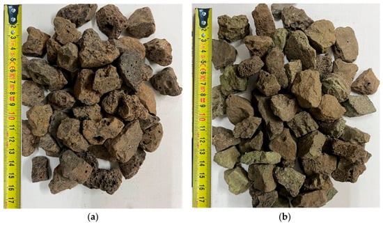
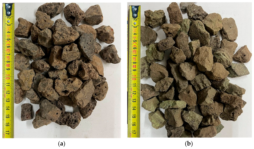
FeCr slag was supplied by Samancor Chrome (Pty) Ltd. (Middleburg, South Africa), and SiMn slag was supplied by Transalloys (Pty) Ltd. (Emalahleni, South Africa). Each slag type was received in bulk amounts of 600 kg. FeCr slag had a particle size distribution of +10–110 mm and SiMn slag had a particle size distribution of +6–60 mm. Both slags were crushed and sieved to +20–40 mm. The physical appearance of the slags can be seen in Figure 1. Constituent oxide phases of both slags were analysed with Inductively Coupled Plasma Optical Emission Spectroscopy (ICP-OES). MINTEK in-house standards (ASD-MET-OES-SP005) for FeCr slags (FeCr_Slags) and ferroalloy slags (FeMn_Slags) were used for the FeCr and SiMn slags, respectively. The chemical analysis results are presented in Table 1.
Figure 1.
Physical appearance of (a) FeCr slag and (b) SiMn slag.
Table 1.
Base metal oxide concentration in slags, mass percent.
2.2. Materials’ Thermochemical Properties and Chemical Stability Tests
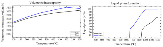
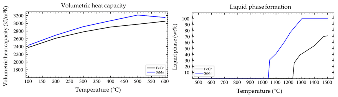
The equilibrium module of the FactSage 8.0 thermochemical simulation software package was used to calculate the slags’ liquid formation temperatures and to predict their specific heat capacities [24]. The chemical composition results presented in Table 1 were used as input parameters, and temperatures between 500 °C and 1500 °C were considered for the liquid phase formation. Specific heat capacity of each slag was evaluated at temperatures in the range of 100–1000 °C. Steenkamp et al. [24] calculated the thermal conductivity of the slags using a model developed by Mills et al. [25], and their calculations produced results comparable to experimental measurements on slags of the same mineral composition. Slag density was analysed by Helium Spectrometry. The average density of the slags was found to be 3305 and 3225 for FeCr slag and SiMn slag, respectively. Equilibrium liquid phase formation temperatures and the volumetric heat capacities of the slags are presented in Figure 2.
Figure 2.
Volumetric heat capacities and liquid phase formation temperatures.
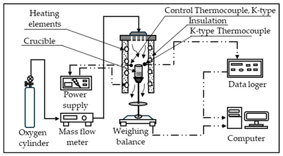
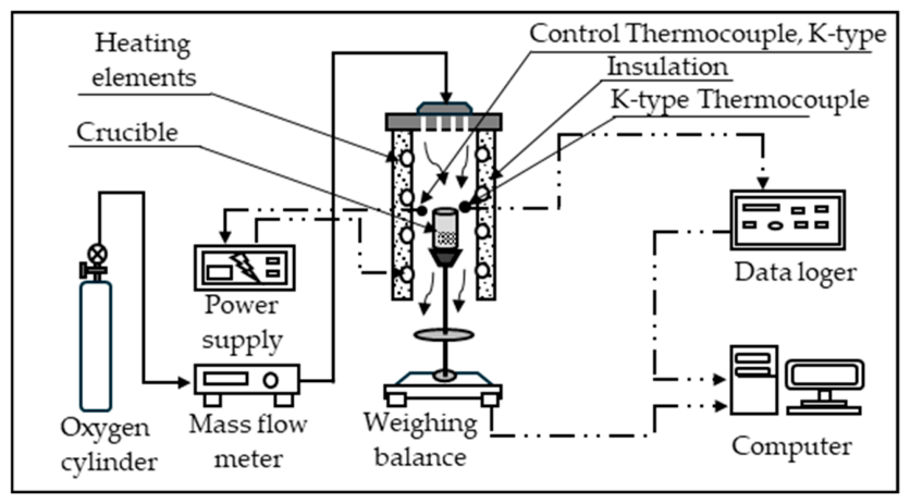
Thermal stability of the slags was evaluated using a MINTEK in-house-built thermogravimetric analyser (TGA), presented in Figure 3. The TGA had a vertical heating chamber of 51 mm diameter that is equipped with molybdenum disilicide (MoSi2) heating elements. The heating chamber was fired at a heating rate of 10 °C per minute. An oxidising condition was created by supplying oxygen through a gas cylinder at 250 kPa. The oxygen flow rate was set at 5 Nl/min using a Bronkhorst mass flow meter (Bronkhorst High-Tech BV, Netherlands), with an accuracy of ±0.1–0.2%. A starting mass of 20 g pulverised slag sample was used for all the tests. The samples were placed in an A5 alumina crucible resting on an AE Adam Precision Balance NBL1602e (Adam Equipment, UK), with a resolution of 0.01 g. The heating chamber temperature was measured with a k-type thermocouple that was connected to an LXI data acquisition unit KEYSIGHT 34972A (Keysight Technologies, CA, USA). Temperature and mass data were collected using MINTEK StarCS V8.1 control software. Three tests were conducted with each slag type at 600 °C, 800 °C, and 1000 °C, with a lower temperature of 400 °C. The heating cycles and their durations are presented in Table 2.
Figure 3.
MINTEK TGA setup for phase transition tests.
Table 2.
TGA heating cycles and their durations.
2.3. Mineral Phase, Grain Size, and Porosity Analyses
The SiMn and FeCr samples were made into slabs and analysed using an automated scanning electron microscopy (autoSEM) on a 4th Generation TESCAN TIMA (TESCAN Group, Czech Republic). The bulk modal mineralogy of each sample was ascertained, albeit semi-quantitatively. The AutoSEM uses Backscattered Electron (BSE) and Energy Dispersive X-ray (EDX) signals from a scanning electron microscope (SEM) to create digital images in which each pixel corresponds to mineral species in the relevant region under the electron beam. Samples were measured using the liberation analysis measurement mode with high X-ray resolution mapping on a TIMA instrument.
Mineral processing (classification and identification) was achieved using a phase list. The detection limit of this technique is approximately 1–3 mass percent. In addition, porosity was determined from the TIMA-mapped fields, in which each particle was segmented to determine its volume. Therefore, the particle volume was defined and compared against the pore volume to determine the porosity percentage. Background data within a particle were treated as pores and used to determine porosity. The porosity of particles at the edges of each slab may not have been fully mapped due to the dimensions of the holder. However, the porosity was calculated based on the mapped portions of the particles and was taken as indicative.
2.4. Experimental Setup for Thermal Storage Tests
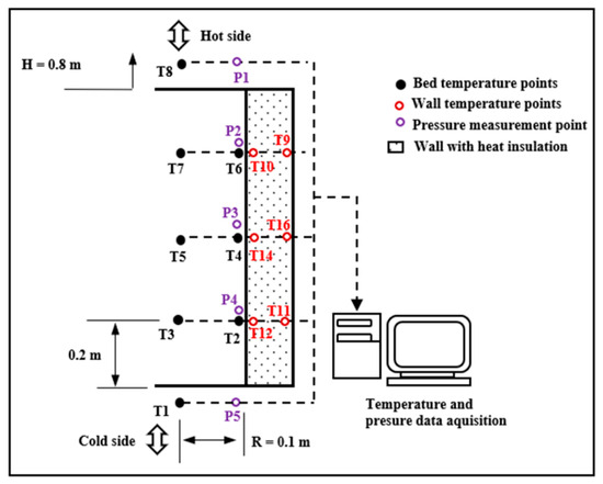
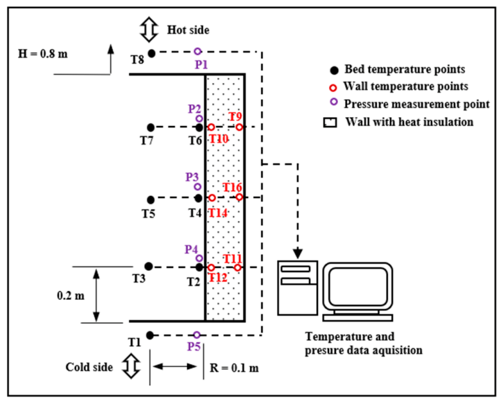
Figure 4 presents a schematic diagram of the thermal storage unit and its instrument configuration. The test column was made of 3 mm mild steel casing with 446 mm outside diameter and 200 mm height. The inside of the steel casing was insulated with a high alumina castable Multicast1800 (Flintcast Refractories, South Africa) to an inside diameter of 200 mm. Four casing pieces were coupled to make a storage unit of 800 mm height. A thermal insulating sheet RS PRO Flame Retardant Superwool 607 Paper (RS Group plc, UK), with 9 mm thickness was used between the casing pieces to provide a seal for the fluid. The packed bed void fraction was determined using the water displacement method in a 5000 mL beaker with a diameter of 200 mm [26].
Figure 4.
Packing dimensions and measuring device placement.
K-type thermocouples were placed at equidistant levels of 200 mm. Temperature points of the packed bed were located at the centre (T3, T5, and T7) and at the wall (T2, T4, and T6). The hot-side (T8) and cold-side (T1) temperature points were located at the centre above and below the packed bed, respectively. The wall temperature points were embedded in the insulation at 5 mm from the inside (T10, T14, and T12) and 5 mm from the outside (T9, T16, and T11) and at the same levels as the packed bed temperature points. Pneumatic gauge pressure sensors with 0–10 bar working range (Gens Sensor, Gems Sensors & Controls, CT, USA) were placed at the packing and the input/outlet temperature point levels (P1-P5) through water-cooled ducting lines that extended 203 mm from the packing. All instrument signals were read and recorded using the Emerson Automation Solutions’ DeltaV Distributed Control System (Emerson Electric Co., MO, USA).
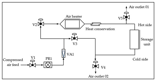
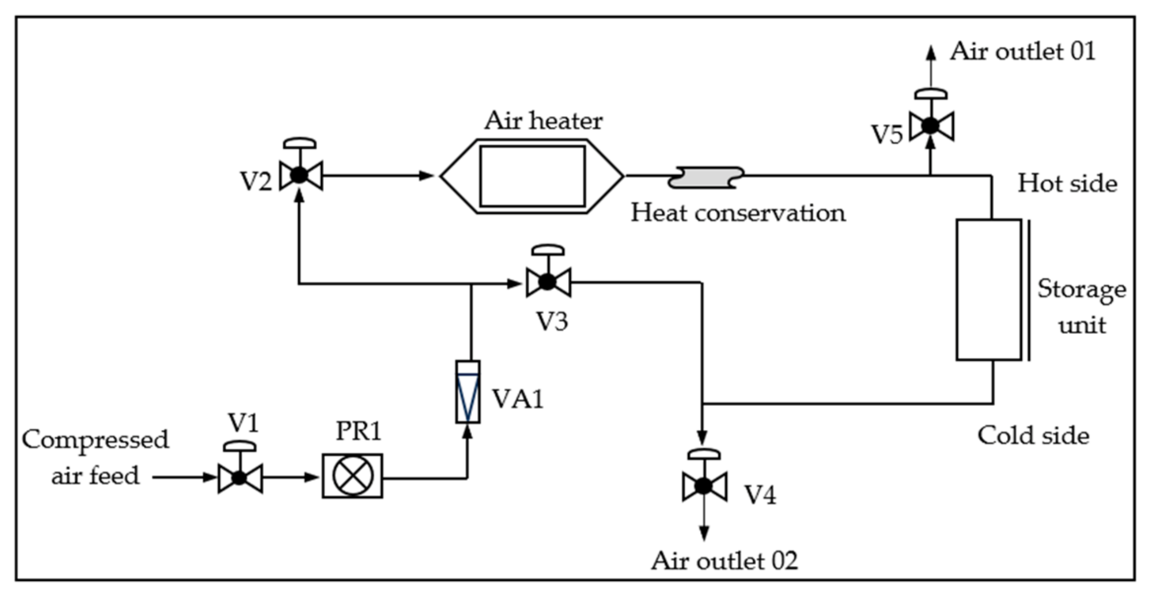
The thermal storage unit was connected to a 30 kW air heater capable of supplying air at 650 °C at 1000–1600 Nl/min. The units were configured to allow for reverse fluid flow during charging and discharging, as depicted in Figure 5. Charging was done from the hot side (T8), and discharging was done by feeding cold fluid from the cold side (T1). This arrangement takes advantage of buoyancy stratification and improves the operational efficiency of energy storage systems.
Figure 5.
Fluid flow configuration of the experimental setup.
The cold air delivery line from the compressed air supply was made up of a ¾ inch galvanised steel pipe. An RS Pro pneumatic regulator (RS Group plc, Italy), with a maximum capacity of 3200 Nl/min was used to control the high-pressure air flow rate. The feed air flow rate was read from a 200–1800 Nl/min variable area PF series plastic flowmeter (P < 12 bar, T < 60 °C, 1 inch (Fem)-P/CARB-80 mmØ/370 mm) with a % F.S accuracy (New Flow, Taiwan). The hot-side and cold-side lines were made of a 1.5-inch black mild steel pipe and covered with a 27 mm layer of RS PRO Flame Retardant Superwool 607 Paper RS Components, UK). Plug valves V4 and V5 were custom-made from stainless steel and were used to direct flow during charging and discharging of the TES unit. V5 was closed while V4 was open during charging, and V4 was closed while V5 was open during discharging.
Two tests were conducted with each slag type (FeCr and SiMn). A single test consisted of two TES cycles. The first cycle involved heating (C1) the packed bed from room temperature to 600 °C at T8 and +400 °C at T1 and then discharging (D1) the TES unit until the outlet fluid temperature reached 400 °C. This was considered usable energy for this work. The second charging cycle (C2) recharged the packed bed to 600 °C at T8 and +300 °C at T1, followed by discharging (D2) until the outlet fluid temperature reached 400 °C. Charging and discharging were done with an air flow rate of 1200 Nl/min.
3. Results
3.1. Mineral Phase, Grain Size, and Porosity Analyses
Table 3 presents the composition of the slag phases identified by AutoSEM. FeCr slag was composed of 67 wt% Cr-bearing alumino-calcium-magnesium silicate (AlCaMg silicate Cr), 23 wt% magnesium aluminate spinel (AlMg oxide), and 6 wt% magnesiochromite-type spinel (CrMgAl oxide). Iron–chromium sulfide (FeCrS), chromite spinel (chromite CrFeAlMg), and magnesiochromite-type spinel (CrMgAl Fe oxide) were detected in trace amounts. Sulfide was present in its matte phase.
Table 3.
Crystalline phases and their composition.
SiMn slag was composed of 60 wt% manganoan calcium silicate (CaMn silicate), 4 wt% calcium silicate (Ca silicate), 6 wt% alumino-calcium manganosilicate (MnCaAl silicate), and 28 wt% manganiferous diopside-type silicate (CaMgMn silicate). Some trace amounts of glassy silicate oxide, diopside-type calcium–magnesium–manganese phase (CaMgMn), and manganese silicide (MnSi) were also detected. Although present in trace amounts, glassy oxides are brittle and can easily break with sudden changes in temperature. MnSi was present as a reduced alloy phase that is entrained in the slag and may compromise the stability of the slag due to high expansion when its temperature increases. MnSi is also likely to oxidise from the supplied oxygen contained in the heat transfer fluid at high temperatures.
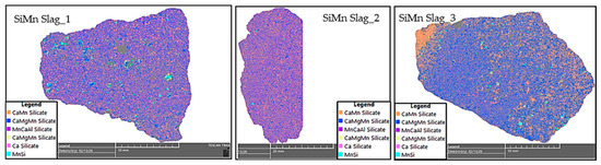
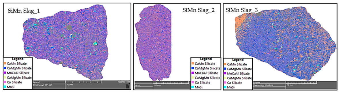
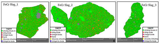
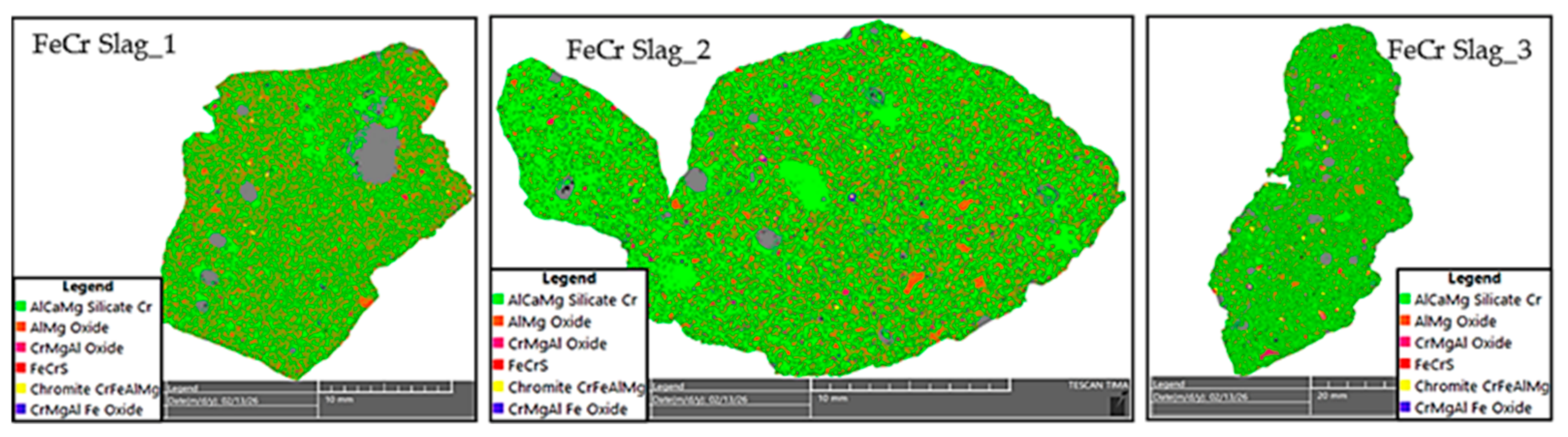
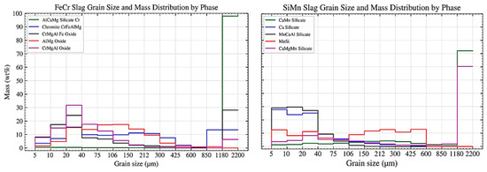
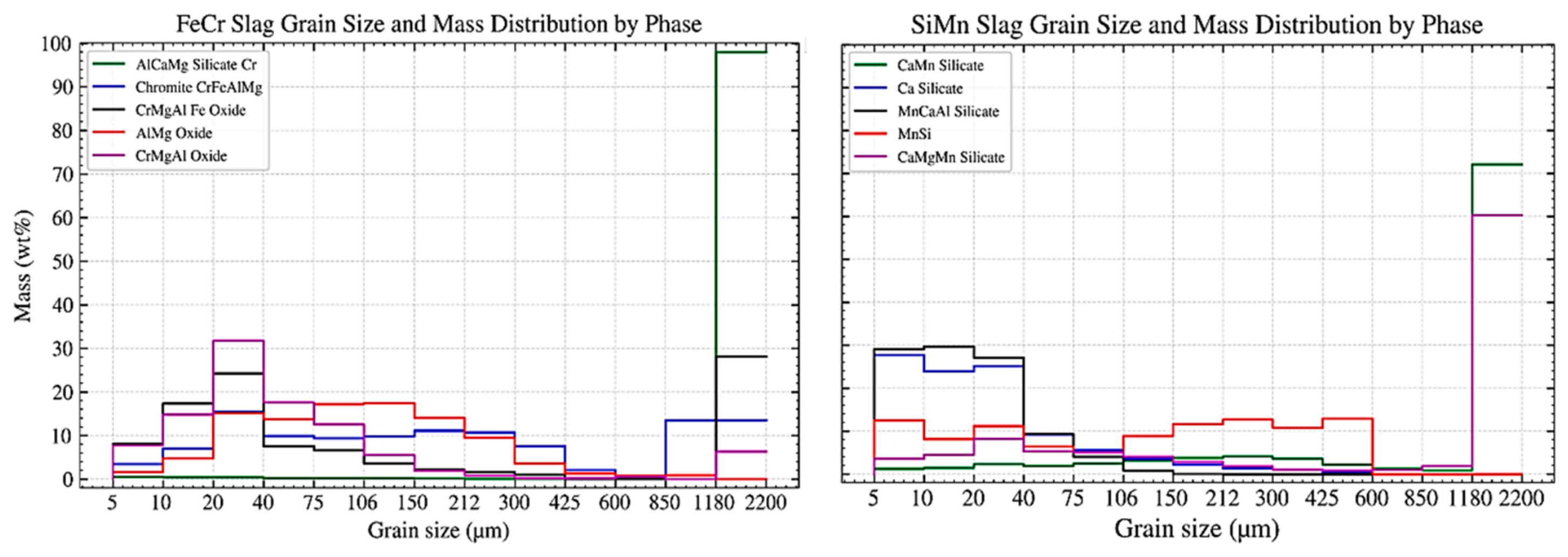
TIMA-mapped fields of three selected particles each from the SiMn and FeCr slags are presented in Figure 6 and Figure 7, respectively. In mineral phases with high abundance, such as AlCaMg silicate in the FeCr slag and CaMn silicate and CaMgMn silicate in the SiMn slag, over 97% of grains are in a size class in the range of 1.1–2.2 mm. The grain size distribution by crystalline phases is presented in Figure 8.
Figure 6.
AutoSEM images of SiMn slag.
Figure 7.
AutoSEM images of FeCr slags.
Figure 8.
FeCr and SiMn grain sizes and mass distributions by phase.
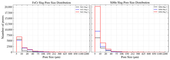
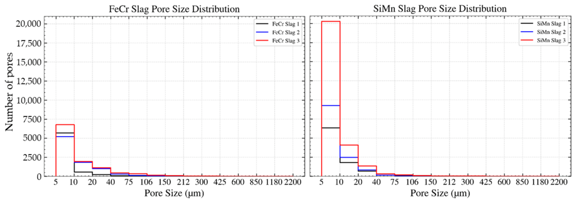
The pores within a particle and at the particle edge were mapped and are presented as grey pockets in Figure 6 for SiMn slag and Figure 7 for FeCr slag. The average porosity ratios of the SiMn and FeCr slags were found to be 0.03 and 0.06, respectively. The pore sizes detected were in the range of 5–106 µm, with a significant number of pores falling within this range. SiMn slag reported the highest number of pores of a finer size. This suggests that Ca silicate and MnCaAl silicate slag phases are highly porous. FeCr slag has about 75% fewer pores compared to SiMn slag. However, it has more pores in the upper size distribution of 75–150 µm. The distribution of pores in the finer size range suggests that there are no pockets of gas in the slags and that the reported porosity is solely due to phase distribution. The pore size distribution is presented in Figure 9.
Figure 9.
FeCr and SiMn slag pore size distributions.
3.2. Chemical Stability Tests
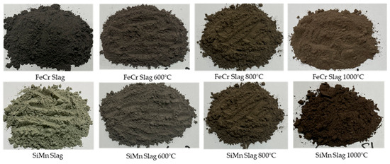
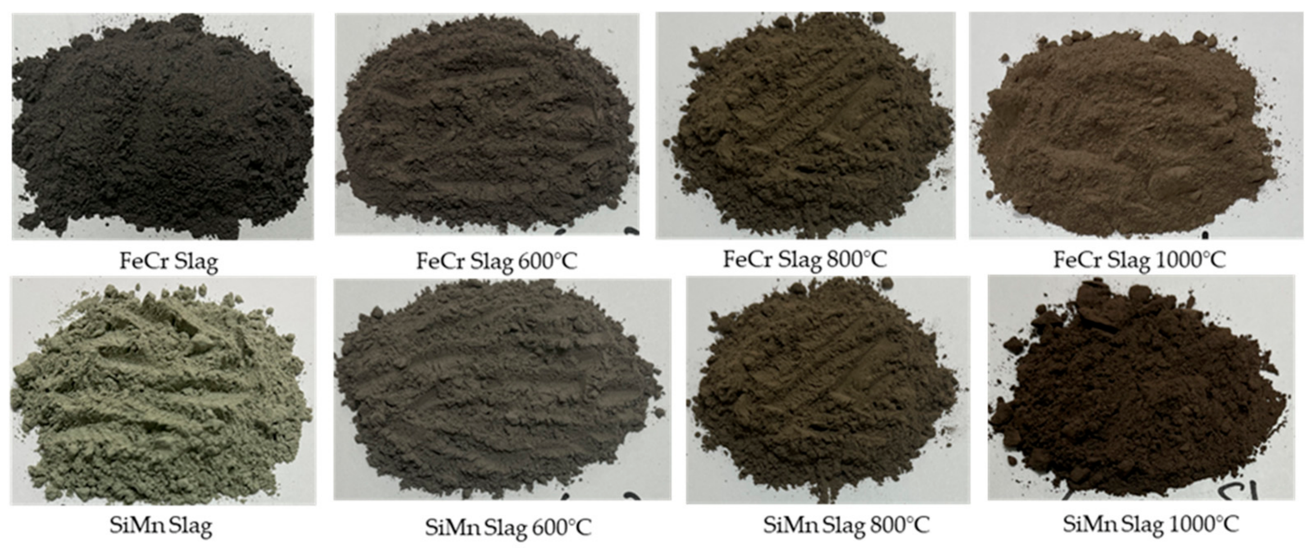
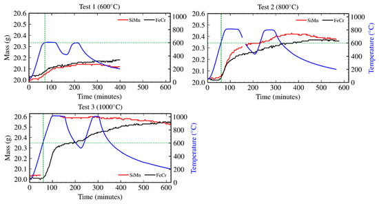
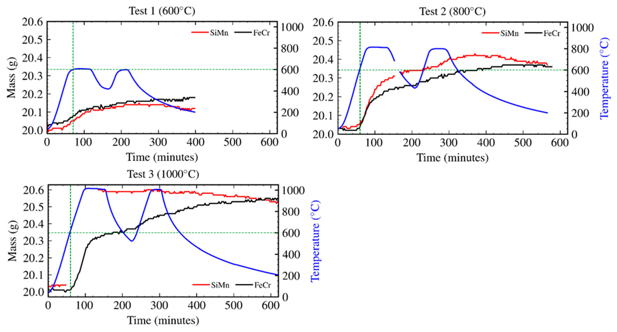
Thermogravimetric analysis shows minimal mass gain in both slags at 600 °C. The mass gain is dependent on temperature, as it increases significantly as the test temperature increases. Phase transformation is expected to result in colour change in the finely ground slag samples. Figure 10 shows the colour changes in the FeCr and SiMn slags after thermal cycling in the ranges of 400–600 °C, 400–800 °C, and 400–1000 °C under oxidising conditions. The recorded mass gains are presented in Figure 11.
Figure 10.
Colour changes in SiMn and FeCr slags at different temperatures and under an oxidising atmosphere.
Figure 11.
Mass changes in SiMn and FeCr slags at different temperatures and under an oxidising atmosphere.
SiMn slag is mostly composed of fully oxidised silicate phases except for the CaMgMn phase, whose constituents, such as Mn, may be present in partially reduced form (Mn2+). However, the manganese silicide phase (MnSi) will readily oxidise to form MnO and SiO2. The formation of these phases is expected to further react with the present phases of CaO and MgO to form a manganese-calcium silicate phase (CaMnSiO4). The recorded mass gains due to phase transition of SiMn slag are 0.9%, 1.85%, and 2.75% for thermal cycling with maximum temperatures of 600 °C, 800 °C, and 1000 °C, respectively.
The spinel and silicate phases contained in the FeCr slag are stable under these test conditions. The phase that is prone to oxidation is the iron–chromium sulfide phase (FeCrS). This phase is expected to break down under oxidising conditions to form ferrochrome oxides (Fe2O3 and Cr2O3) or a ferrochrome spinel phase (FeCr2O4) while releasing SO2 gas. The recorded mass gains due to phase transition of FeCr slag are 0.7%, 2.2%, and 3.0% for thermal cycling with maximum temperatures of 600 °C, 800 °C, and 1000 °C, respectively.
3.3. Thermal Cycling Tests
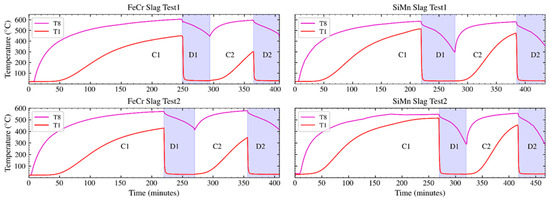
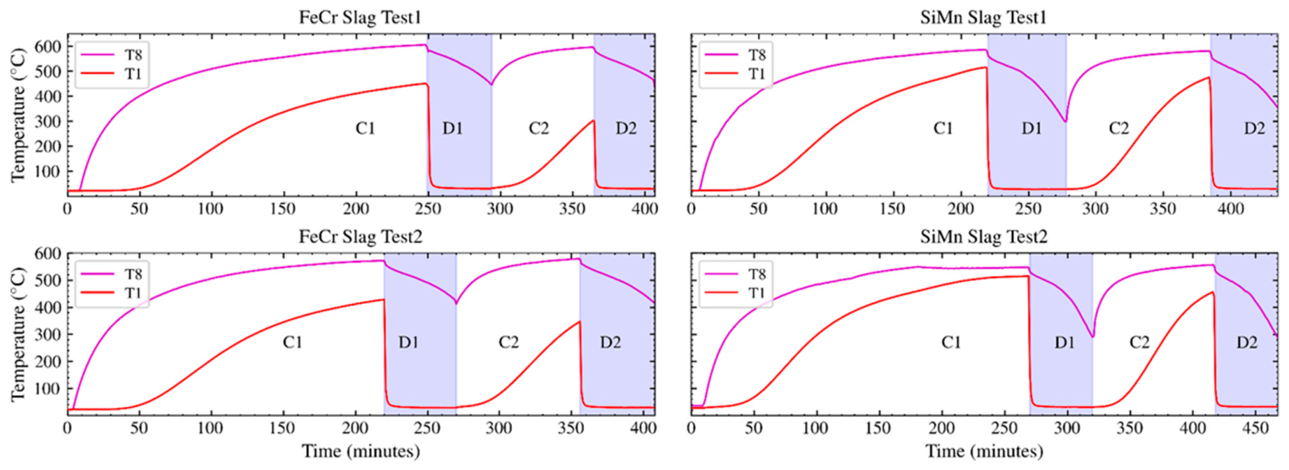
Two tests were conducted with each slag type. A single test consisted of two thermal energy storage cycles. The first charging cycle (C1) involved heating the packed bed from room temperature to 600 °C at the hot-side inlet temperature point (T8) and +400 °C at the cold-side exit temperature point (T1). The first discharging cycle (D1) was done by feeding cold air at 25 °C from the cold side of the storage unit until the exit temperature point (T8) reached 400 °C, which was considered usable energy for this work. The second charging cycle (C2) heated the packed bed to 600 °C at the hot-side temperature point (T8) and +300 °C at the cold-side temperature point (T1), followed by discharging (D2) until the outlet fluid temperature at the hot side (T8) reached 400 °C.
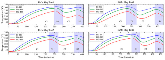
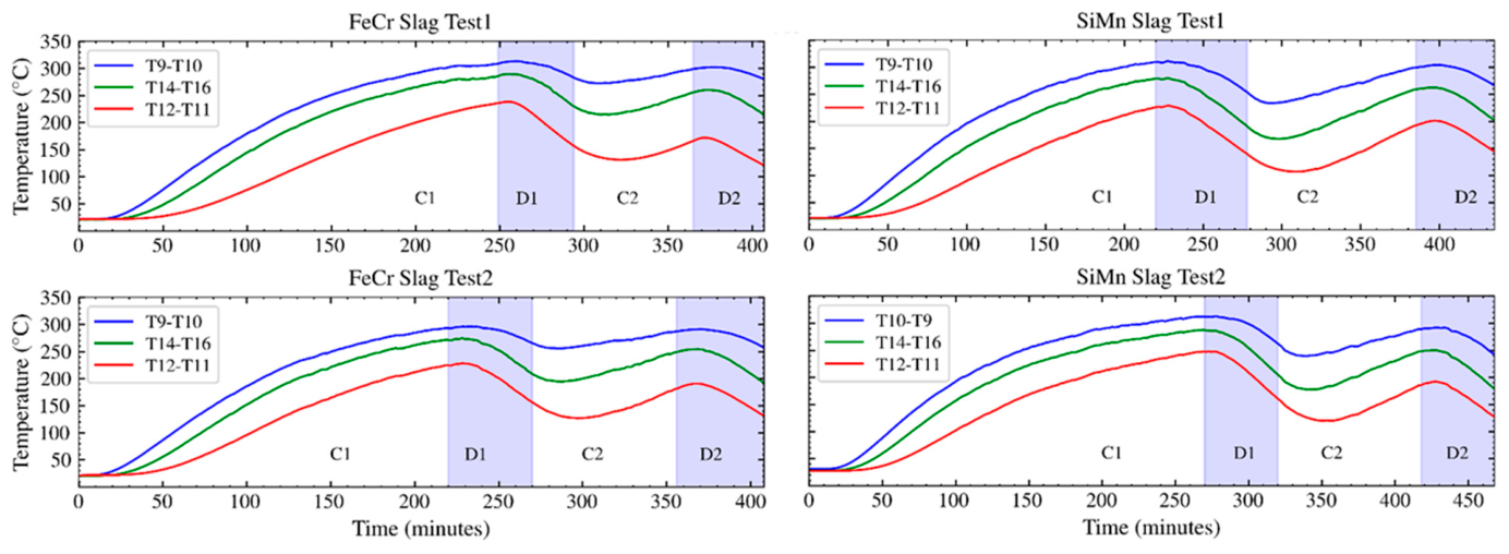
The temperature readings from the thermal cycles recorded at the cold-side and hot-side temperature points are presented in Figure 12. The wall temperature of the packed section was averaged between the innermost and outermost temperature points. The resulting wall temperatures show that the hot side of the unit remains hotter during charging and discharging. Wall temperatures of up to 300 °C were recorded during the tests from both slags, as presented in Figure 13.
Figure 12.
Hot-side and cold-side temperature readings in thermal cycling tests.
Figure 13.
Averaged wall temperature readings in thermal cycling tests.
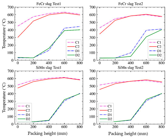
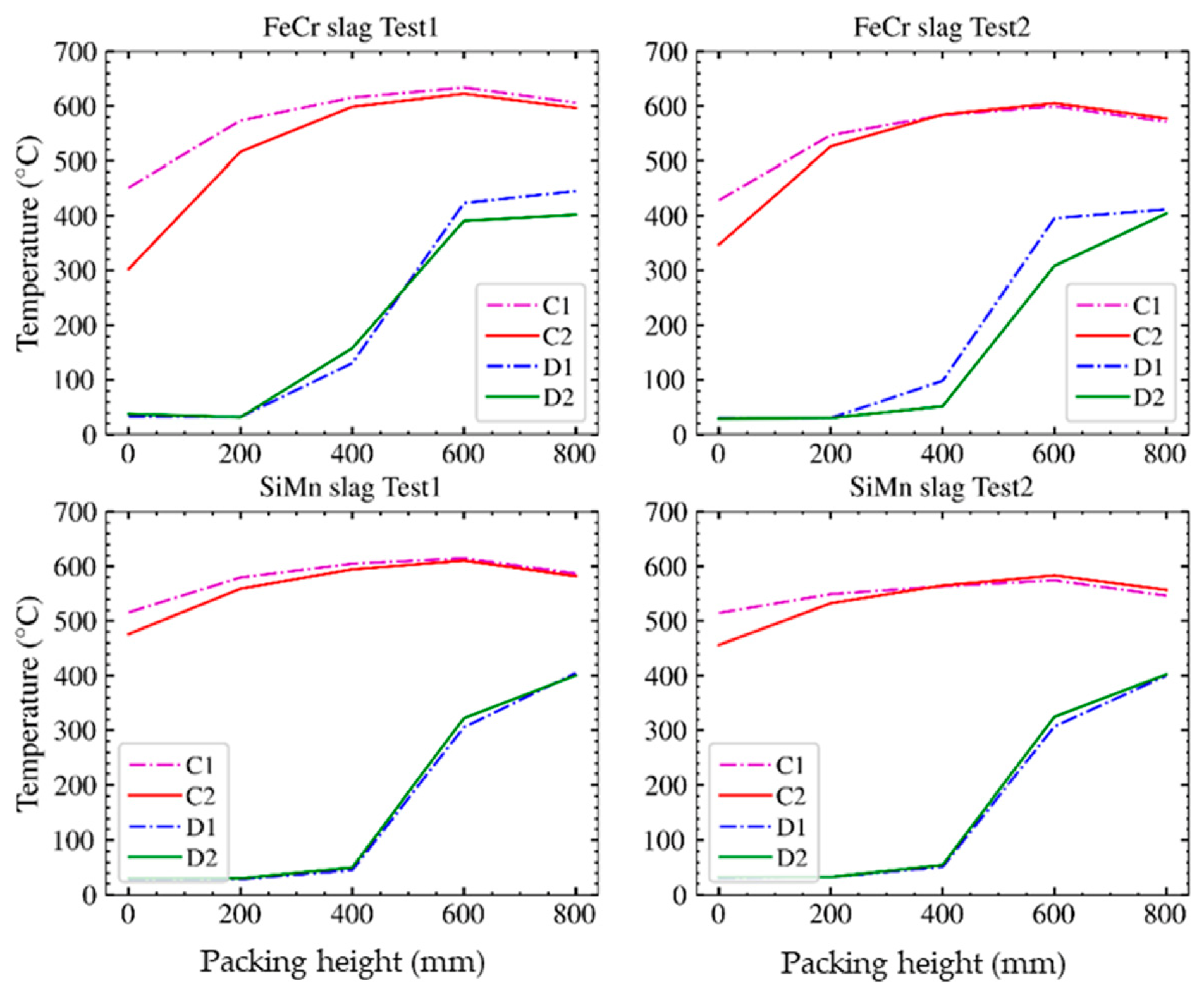
The charged and discharged packed bed axial temperature profiles are presented in Figure 14. The first charging cycle resulted in more thermal energy stored due to the extended charging period for all tests. SiMn slag achieved higher temperature profiles in the second cycle compared to FeCr slag. This highlights its higher volumetric heat capacity, as observed in Figure 2. More energy is still available in the packed bed of FeCr slag compared to SiMn slag after discharging all usable energy. The higher gradient on the thermocline for FeCr slag suggests that the effect of the material’s volumetric heat capacity also affects its ability to release thermal energy when it is discharged.
Figure 14.
Packed bed axial temperature profiles of the charged (C) and discharged (D) thermal storage unit.
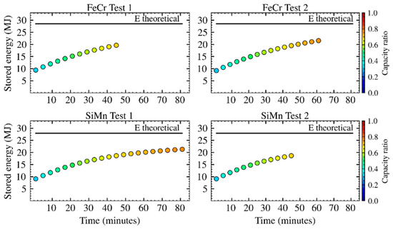
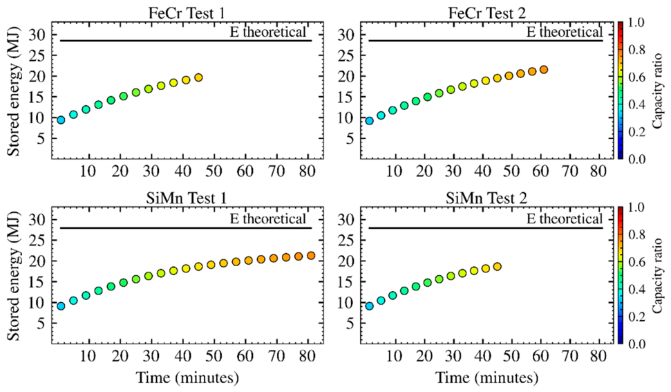
The packed bed can be charged to a maximum temperature of 630 °C across its entire length. The maximum stored energy is referred to as the theoretical stored energy. The maximum theoretical stored energy further hints at the maximum storage capacity of the filler materials in a TES system. Figure 15 shows the exploited storage capacity of the slags during C2 of each test and the theoretical maximum energy storage capacity. The ratio of used storage capacity at the end of a charging cycle to the theoretical storage capacity is referred to as the capacity ratio. Test 1 and Test 2 of the FeCr slag tests reached capacity ratios of 69% and 75%, respectively. SiMn slag tests reached capacity ratios of 76% and 67% during C2 of Test 1 and Test 2, respectively.
Figure 15.
Stored energy from C2 against the theoretical maximum energy storage capacity.
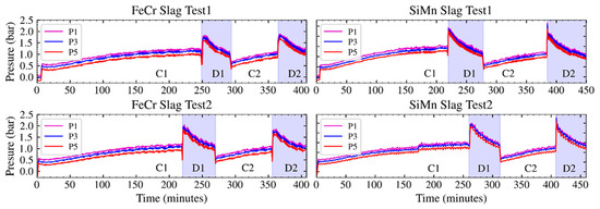
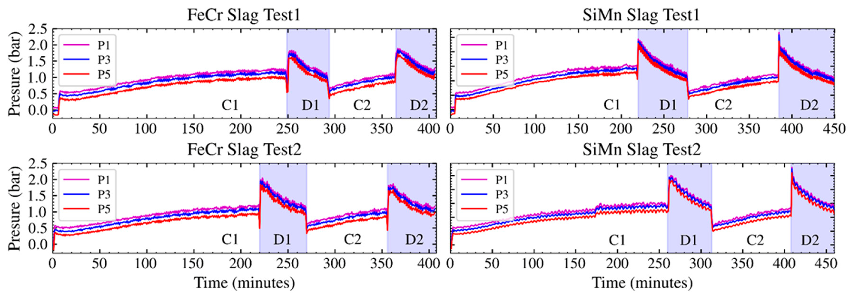
The measured packed bed pressure differences are presented in Figure 16. The recorded data shows that the packed bed pressure drop increases with increasing fluid temperature. This is due to thermal expansion, which reduces the fluid density and results in high fluid linear velocity. This further increases the energy required to drive the fluid through the packed bed. The packing pressure increases significantly when the fluid is heated within the packed bed during discharging. There was no significant difference in pressure drop between the two slags. This was expected, as the physical makeup of the packing remained the same during the thermal cycles for both slag types.
Figure 16.
Packed bed pressure drop measured from thermal cycling tests.
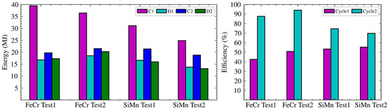
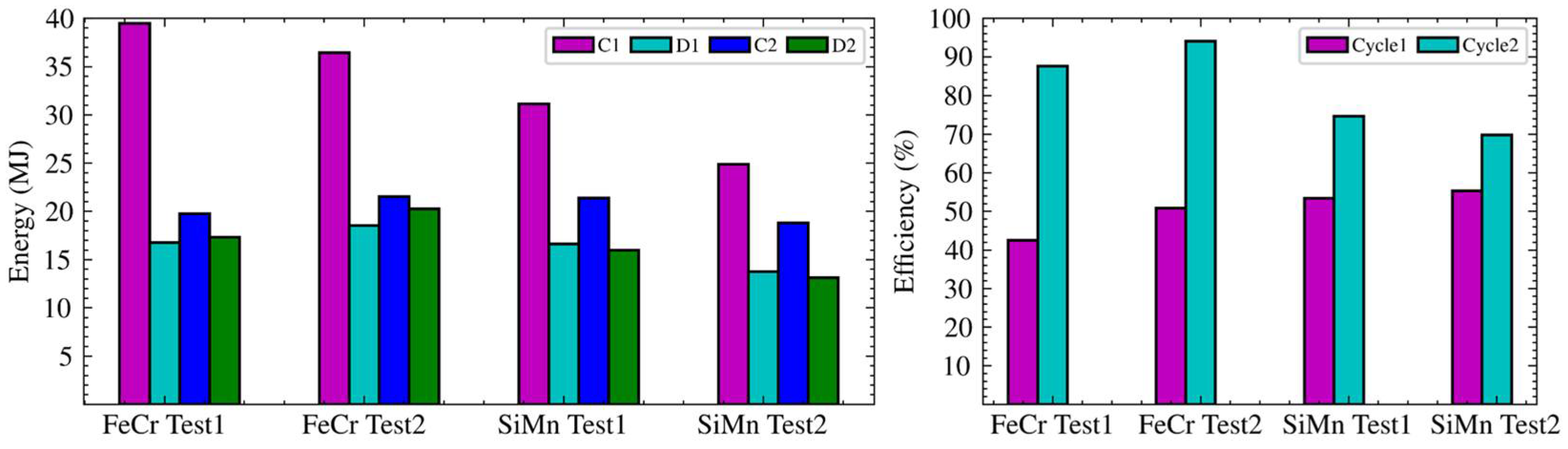
The thermal energy used for charging the packed bed, the thermal energy recovered, and the cycles’ efficiencies are presented in Figure 17. Less energy was required in Test 2 for both slags because of residual energy from Test 1. More energy was required to charge the packed bed of FeCr slag compared to the SiMn slag. There was no significant difference in energy required for the second thermal storage cycle (C2). However, less energy was recovered from SiMn slag compared to FeCr slag during the second discharging cycle (D2).
Figure 17.
Energy stored during charging against energy recovered during discharging.
The thermal energy storage capacity of the slags was evaluated based on the average specific energy recovered from the two thermal energy storage cycles. In total, 79.86 W/kg and 76.79 W/kg were recovered from FeCr slag and SiMn slag, respectively, during the first discharge (D1) in both Test 1 and Test 2. Further, 84.56 W/kg and 76.30 W/kg were recovered from FeCr slag and SiMn slag, respectively, during the second discharge (D2) in both Test 1 and Test 2.
The performance of the different slags was assessed by computing thermal storage cycles efficiencies. This was based on the amount of stored energy and the amount of useful energy recovered. The efficiency of the first cycle was low, as expected, because of the energy required to charge the packed bed from room temperature to the point where useful energy is added to the packing. FeCr slag achieved 88% and 94% efficiency during the second thermal cycle (C2) of Test 1 and of Test 2, respectively. SiMn slag achieved 75% and 70% efficiency during the second thermal cycle (C2) of Test 1 and of Test 2, respectively.
4. Discussion
4.1. Thermophysical Properties and Liquid Phase Formation
The primary indicators of a good thermal energy storage medium are the thermochemical properties. The FeCr and SiMn slags’ thermochemical properties are consistent with ferroalloy slags and have comparable densities, and , respectively. These densities are comparable with other candidate materials, such as typical slags from the steel industry (3430–3770 ) [14], copper slags (3500–3700 ) [18], castable ceramics [27], and high-temperature concrete [28]. Comparable densities translate to comparable thermal capacities, as the typical specific heat capacity of most candidate filler materials is in the range of 700–1000 in the temperature range of 100–1000 °C.
The liquid phase formation temperature of FeCr (1230 °C) is considerably higher than that of SiMn (1040 °C). This means that FeCr slag can be used in systems with much higher service temperatures, up to 1200 °C. The low liquid phase formation temperature of SiMn slag results from the fluxing agents (CaO/CaCO3 and SiO2) added during the production process to control slag chemistry and to control process parameters such as melting temperature, basicity, and viscosity for improved metal recovery. The high liquid phase formation temperature of FeCr slag is due to the high concentration of Al2O3 (33 wt%) and lower concentration of SiO2 (28 wt%). Fluxing strategies can be implemented in both production processes to produce slags with desirable qualities for use in TES systems.
4.2. Mineral Phase Transition, Grain Size, and Porosity Distribution
The number of mineral phases present in filler materials may contribute to chemical instability due to phase transformation. However, the phases that are susceptible to phase transformation are present in these slags in trace amounts. Mass gain in SiMn slag is caused by an entrained MnSi alloy phase that makes up only 0.17 wt%. The oxidised SiMn phase forms stable silicate phases after the first heating cycle. This is observed in the stable mass after the first heating cycle and during the cooling stage of the TG tests. Stable phases of Fe2O3 and Cr2O3 or FeCr2O4 are expected to form during the first charging cycle from the oxidation of FeCrS in FeCr slag. This is also evident in the stable masses after the first heating cycle and during the cooling stage in the TG tests. FeCrS is also present in trace amounts (0.5 wt%) in the FeCr slag.
The formation of stable phases after the first cycle is consistent with observations from electric arc furnace slags, copper slags, and steel slags as reported in the literature [14,18,29]. The observed mass gains can be reduced by ensuring that the selected slags have no metal entrainment by introducing a sorting step. However, high-temperature stabilisation of oxides should be done by heating the slags at 1000 °C under oxidising conditions before they are used in high-temperature TES systems. Mass gains of 3% and 2.75% from FeCr and SiMn slags at 1000 °C to form stable phases suggest that the slags are chemically stable and can be considered for systems with service temperatures up to 1000 °C.
4.3. Grain Size and Porosity Distribution
The dominant phases, such as CaMn silicate (60 wt%) and CaMgMn silicate (28 wt%) for SiMn slag and AlCaMg silicate Cr (67 wt%) for FeCr slag, form the coarser grain (1180–2200 µm) distribution in the slags. Meanwhile, the minor phases are of finer grain size distributions. Small-grain-sized phases are associated with higher mechanical strength due to enhanced bond density at grain boundaries [30]. This suggests that the slags may have good mechanical stability due to fewer phases in the larger grain size distribution. However, mechanical stability studies, such as compression strength analysis, thermal expansion analysis, and material decrepitation under thermal cycling, were out of the scope of this work and need to be carried out in future work. The pore sizes of the slags were detected in the range of 5–75 µm, with more than 50% of the detected pores falling below 10 µm. This indicates the absence of macrocracks in the slags. The reported porosity values of 6% for SiMn and 3% for FeCr slags are consistent with experimental values of 3–5% reported in the literature for steel slags [14].
4.4. System Thermal Cycling Performance and Operability
The good thermophysical properties of the slags were confirmed through thermal cycling tests. SiMn slag stores and releases energy efficiently compared to FeCr slag due to its superior volumetric heat capacity. This is also evident from the consistent charged and discharged packed bed temperature profiles. However, both slags achieved comparable volumetric heat capacity ratios of 0.66–0.76. The variations in the capacity ratio between tests indicate its dependence on test conditions. Capacity ratios above 0.5 are deemed adequate for sensible energy storage systems [31]. The average energy density per volume of packed slags was found to be 187 kWh/m3 for FeCr slag and 165 kWh/m3 for SiMn slag, respectively, during the discharge cycles with air temperatures above 400 °C.
The encompassing wall played a role in the recorded TES performance due to the high packed bed aspect ratio (AR = 4:1). The high aspect ratio also contributed to the high pressure drop that was recorded during the experiments. The small particle size of 20–40 mm made its own contribution to the high pressure drop. However, particle size distribution played a significant role in the packed bed thermocline, with finer particle sizes leading to sharper temperature fronts. The pressure drop can be reduced by optimising the packing aspect ratio to 1 as reported in [16]. This would also nullify the influence of the wall on a system’s thermal storage performance.
Improved system efficiencies of up to 94% were recorded in the second cycles. This is an indicative value because the influence of the encompassing wall was not quantified. Low efficiencies recorded from the first cycles were due to the initial heating up of the packing and the wall from room temperature to the thermal cycling temperature of 400–600 °C. The energy required for pumping the HTF through the packed bed should be included in efficiency calculations to reflect the actual system’s efficiency. Future studies will include the design of optimum storage units with features such as optimised pressure drop and thermal energy containment during idling periods.
5. Conclusions
FeCr and SiMn slags are good candidates for use in sensible TES systems due to their high densities of 3225–3305 . Liquid phase formation and phase transition findings suggest that the slags are chemically stable up to 1000 °C. However, process improvement during their production or sorting during materials preparation is required to reduce entrained alloy. High-temperature curing is required to stabilise oxide phases contained in the slags before they can be used as filler materials. The slags do not have macrocracks even after crushing in material preparation. The reported porosity of 3–6% suggests that the slags have good mechanical properties and are suitable for long-term use. The slags have high energy density (165–187 kWh/m3) during discharging cycles with air temperatures at 400–600 °C. The studied TES system confirmed the feasibility of using air as the HTF at high temperatures. However, the packed bed needs to be optimised for pressure drop and temperature fronts to improve the system’s overall efficiency.
Author Contributions
Conceptualisation, S.N.S. and E.M.; methodology, S.N.S. and M.I.K.; investigation, S.N.S.; resources, E.M.; data curation, M.I.K.; writing—original draft preparation, S.N.S.; writing—review and editing, M.I.K. and E.M.; visualisation, S.N.S. and M.I.K.; supervision, E.M.; project administration, S.N.S. and E.M.; funding acquisition, E.M. All authors have read and agreed to the published version of the manuscript.
Funding
This work is published with the permission of MINTEK under PDR-260035, PM53-ThermalStorage.
Data Availability Statement
The original contributions presented in the study are included in the article, further inquiries can be directed to the corresponding authors.
Acknowledgments
The authors would like to extend their gratitude to Samancor Chrome (Pty) Ltd. (South Africa) and Transalloys (Pty) Ltd. (South Africa) for providing the raw materials used in this study.
Conflicts of Interest
Authors Sifiso N. Sambo, Mopeli Khama, and Elias Matinde were employed by MINTEK during the writing of this article. The authors declare that this study received funding from MINTEK. The funder was not involved in the study design, collection, analysis, interpretation of data, the writing of this article or the decision to submit it for publication.
References
- Admin. Industrial Furnace Waste Slag Recycling Services Market. 2025. Available online: https://pmarketresearch.com/it/industrial-furnace-waste-slag-recycling-services-market/ (accessed on 28 February 2026).
- Agalit, H.; Zari, N.; Maaroufi, M. Thermophysical and chemical characterization of induction furnace slags for high temperature thermal energy storage in solar tower plants. Sol. Energy Mater. Sol. Cells 2017, 172, 168–176. [Google Scholar] [CrossRef] [Scilit]
- Calderón, A.; Palacios, A.; Barreneche, C.; Segarra, M.; Prieto, C.; Rodriguez-Sanchez, A.; Fernández, A.I. High temperature systems using solid particles as TES and HTF material: A review. Appl. Energy 2018, 213, 100–111. [Google Scholar] [CrossRef] [Scilit]
- Calderón-Vásquez, I.; Cortés, E.; García, J.; Segovia, V.; Caroca, A.; Sarmiento, C.; Barraza, R.; Cardemil, J.M. Review on modeling approaches for packed-bed thermal storage systems. Renew. Sustain. Energy Rev. 2021, 143, 110902. [Google Scholar] [CrossRef] [Scilit]
- Calderón-Vásquez, I.; Segovia, V.; Cardemil, J.M.; Barraza, R. Assessing the use of copper slags as thermal energy storage material for packed-bed systems. Energy 2021, 227, 120370. [Google Scholar] [CrossRef] [Scilit]
- Chavan, S.; Rudrapati, R.; Manickam, S. A comprehensive review on current advances of thermal energy storage and its applications. Alex. Eng. J. 2022, 61, 5455–5463. [Google Scholar] [CrossRef] [Scilit]
- Du Preez, S.P.; Van Kaam, T.P.M.; Ringdalen, E.; Tangstad, M.; Morita, K.; Bessarabov, D.G.; Van Zyl, P.G.; Beukes, J.P. An Overview of Currently Applied Ferrochrome Production Processes and Their Waste Management Practices. Minerals 2023, 13, 809. [Google Scholar] [CrossRef] [Scilit]
- Enemuo, M.; Enemuo, N.; Taleghani, A.D.; Ogunmodimu, O. Slags as Thermal Energy Storage Media for Concentrated Solar Power and Renewable Energy Integration. Energy Storage 2025, 7, e70274. [Google Scholar] [CrossRef] [Scilit]
- FactSage.com. Available online: https://www.factsage.com/ (accessed on 20 August 2022).
- González-Roubaud, E.; Pérez-Osorio, D.; Prieto, C. Review of commercial thermal energy storage in concentrated solar power plants: Steam vs. molten salts. Renew. Sustain. Energy Rev. 2017, 80, 133–148. [Google Scholar] [CrossRef] [Scilit]
- Grirate, H.; Agalit, H.; Zari, N.; Elmchaouri, A.; Molina, S.; Coutuorier, R. Experimental and numerical investigation of potential filler materials for thermal oil thermocline storage. Sol. Energy 2016, 131, 260–274. [Google Scholar] [CrossRef] [Scilit]
- Grosu, Y.; Ortega-Fernández, I.; González-Fernández, L.; Nithiyanantham, U.; Baba, Y.F.; Al Mers, A.; Faik, A. Natural and by-product materials for thermocline-based thermal energy storage system at CSP plant: Structural and thermophysical properties. Appl. Therm. Eng. 2018, 136, 185–193. [Google Scholar] [CrossRef] [Scilit]
- Hänchen, M.; Brückner, S.; Steinfeld, A. High-temperature thermal storage using a packed bed of rocks—Heat transfer analysis and experimental validation. Appl. Therm. Eng. 2011, 31, 1798–1806. [Google Scholar] [CrossRef] [Scilit]
- Haunstetter, J.; Krüger, M.; Zunft, S. Experimental Studies on Thermal Performance and Thermo-Structural Stability of Steelmaking Slag as Inventory Material for Thermal Energy Storage. Appl. Sci. 2020, 10, 931. [Google Scholar] [CrossRef] [Scilit]
- Yang, C.-H. International Energy Agency’s approaches to low-carbon energy transitions and just transitions in emerging economies. In Energy Economics, Finance, and Management in Developing and Emerging Economies; Elsevier: Amsterdam, The Netherlands, 2026; pp. 241–261. [Google Scholar] [CrossRef] [Scilit]
- Krüger, M.; Haunstetter, J.; Hahn, J.; Knödler, P.; Zunft, S. Development of Steelmaking Slag Based Solid Media Heat Storage for Solar Power Tower Using Air as Heat Transfer Fluid: The Results of the Project REslag. Energies 2020, 13, 6092. [Google Scholar] [CrossRef] [Scilit]
- Laing, D.; Steinmann, W.-D.; Tamme, R.; Richter, C. Solid media thermal storage for parabolic trough power plants. Sol. Energy 2006, 80, 1283–1289. [Google Scholar] [CrossRef] [Scilit]
- Lopez Ferber, N.; Al Naimi, K.M.; Hoffmann, J.-F.; Al-Ali, K.; Calvet, N. Development of an electric arc furnace steel slag-based ceramic material for high temperature thermal energy storage applications. J. Energy Storage 2022, 51, 104408. [Google Scholar] [CrossRef] [Scilit]
- McGregor, C.; Snyman, L.C. Design and performance testing of a structured packing for thermal energy storage applications. In Proceedings of the International Heat Transfer Conference 17, Cape Town, South Africa, 14–18 August 2023; p. 11. [Google Scholar] [CrossRef] [Scilit]
- Muche, D.N.F.; Marple, M.A.T.; Hung, I.; Gan, Z.; Castro, R.H.R.; Sen, S. Size-Induced Structural Disorder Enables Ultrahard Oxides. J. Phys. Chem. C 2017, 121, 13898–13905. [Google Scholar] [CrossRef] [Scilit]
- Sambo, S.N.; Steenkamp, J.D.; Bezuidenhout, P.J.A. A Desktop Study on the Potential Use of South African Slags as Thermal Storage Medium. In Advances in Pyrometallurgy; TMS Annual Meeting & Exhibition; Springer: Switzerland, 2023; pp. 253–265. [Google Scholar] [CrossRef] [Scilit]
- Ortega-Fernández, I.; Calvet, N.; Gil, A.; Rodríguez-Aseguinolaza, J.; Faik, A.; D’Aguanno, B. Thermophysical characterization of a by-product from the steel industry to be used as a sustainable and low-cost thermal energy storage material. Energy 2015, 89, 601–609. [Google Scholar] [CrossRef] [Scilit]
- Sambo, S.N. The Development of a Heat Transfer Model for a Shaft Kiln to Preheat Manganese Ore with Hot Air. Master’s Thesis, Vaal University of Technology, Vanderbijl Park, South Africa, 2023. [Google Scholar]
- Tiskatine, R.; Eddemani, A.; Gourdo, L.; Abnay, B.; Ihlal, A.; Aharoune, A.; Bouirden, L. Experimental evaluation of thermo-mechanical performances of candidate rocks for use in high temperature thermal storage. Appl. Energy 2016, 171, 243–255. [Google Scholar] [CrossRef] [Scilit]
- Skuntz, M.E.; Elander, R.; Al Azawii, M.; Bueno, P.; Anderson, R. System efficiency of packed bed TES with radial flow vs. axial flow—Influence of aspect ratio. J. Energy Storage 2023, 72, 108463. [Google Scholar] [CrossRef] [Scilit]
- Vigneshwaran, K.; Singh Sodhi, G.; Muthukumar, P.; Subbiah, S. Concrete based high temperature thermal energy storage system: Experimental and numerical studies. Energy Convers. Manag. 2019, 198, 111905. [Google Scholar] [CrossRef] [Scilit]
- Wang, Y.; Wang, Y.; Li, H.; Zhou, J.; Cen, K. Thermal properties and friction behaviors of slag as energy storage material in concentrate solar power plants. Sol. Energy Mater. Sol. Cells 2018, 182, 21–29. [Google Scholar] [CrossRef] [Scilit]
- Yang, L.; Li, C.; Da, Y.; Zhang, J.; Wang, G. Environmentally responsible steel-slag-based solid particles for highly efficient and durable solar selective absorptance and thermal storage. J. Clean. Prod. 2024, 447, 141533. [Google Scholar] [CrossRef] [Scilit]
- Yin, M.; Xiong, Y.; Zhang, A.; Li, X.; Wu, Y.; Zhang, C.; Zhao, Y.; Ding, Y. Non-Ferrous Metal Smelting Slags for Thermal Energy Storage: A Mini Review. Buildings 2025, 15, 2376. [Google Scholar] [CrossRef] [Scilit]
- Zanganeh, G.; Pedretti, A.; Zavattoni, S.; Barbato, M.; Steinfeld, A. Packed-bed thermal storage for concentrated solar power—Pilot-scale demonstration and industrial-scale design. Sol. Energy 2012, 86, 3084–3098. [Google Scholar] [CrossRef] [Scilit]
- Zxferroalloy. Ferrosilicon Slag: Composition, Uses, Specifications & 2026 Industry Trends. ZHENXIN Ferroalloy Supplier. 2026. Available online: https://zxferroalloy.com/resource/ferrosilicon-slag-composition-uses-specifications-2026-industry-trends/ (accessed on 28 February 2026).

Disclaimer/Publisher’s Note: The statements, opinions and data contained in all publications are solely those of the individual author(s) and contributor(s) and not of MDPI and/or the editor(s). MDPI and/or the editor(s) disclaim responsibility for any injury to people or property resulting from any ideas, methods, instructions or products referred to in the content. |
© 2026 by the authors. Licensee MDPI, Basel, Switzerland. This article is an open access article distributed under the terms and conditions of the Creative Commons Attribution (CC BY) license.