


Abstract
External stray magnetic fields from permanent magnet synchronous motors (PMSMs) may cause electromagnetic interference to nearby equipment and limit their application in space-constrained systems. To address this issue, this paper investigates the use of laminated Co-based amorphous ribbon shields for stray-field suppression. An efficient equivalent modeling method is proposed for the simulation of such multilayer thin shielding structures, in which the laminated shield is replaced by an equivalent single-layer model while preserving its macroscopic shielding behavior. The method is first assessed in 2-D through comparisons between refined laminated and simplified equivalent models under both linear permeability and nonlinear magnetization-curve descriptions, and is then extended to 3-D PMSM shielding analysis under static and rotating no-load conditions with experimental validation. Results show that the 10-layer amorphous ribbon shield, with a total thickness of 420 μm, achieves a maximum shielding effectiveness of 7.9 dB at a measurement distance of two motor radii. The maximum deviation between simulation and experiment is 7.4%, and the equivalent model reduces computation time by 28% relative to the refined model. This method provides an accurate and efficient approach for the analysis and design of compact low-frequency magnetic shields for PMSMs.
1. Introduction
Permanent magnet synchronous motors (PMSMs) offer significant advantages including high precision, rapid response, compact size, lightweight construction and strong shock resistance, leading to their widespread adoption in aerospace, naval engineering, military defense and new energy vehicles [1,2,3,4,5,6,7]. However, magnet leakage from such motors may disrupt critical functions or even cause catastrophic failures in sensitive applications, such as military magnetic stealth operations [8], high-precision robotic servo system [9] and electric drive controls for new energy vehicles [10]. While internal electromagnetic characteristics including air-gap flux density [11], magnetomotive force (MMF) [12] and motor control strategy design [13] have been addressed in many studies [14,15,16], little is known about their stray external magnetic fields. Research on shielding of such an external magnetic field of PMSMs is still lacking.
Passive magnetic shielding, which effectively suppresses static, alternating, and random magnetic fields, operates through magnetic flux diversion in high-permeability materials and eddy-current opposition in conductive materials [17,18]. For PMSMs, the air-gap magnetic field lies in the low-frequency range [19,20], making high-permeability materials the primary choice. Compared with traditional permalloy structures that require complex multilayer welding and precise nesting resulting in high cost, heavy weight, and structural complexity [21,22], amorphous ribbons offer higher permeability, greater saturation flux density, and better frequency stability [23,24], while their flexible application methods simplify fabrication and significantly enhance cost-efficiency and practicality [25,26]. Soft magnetic amorphous ribbons are therefore considered promising materials for shielding applications in PMSMs.
The shielding layer investigated in this study consists of laminated amorphous ribbons, each with a thickness of 24 μm, separated by 20 μm insulating films between adjacent layers. Explicit layer-by-layer modeling of such a multilayer ultrathin structure in finite element analysis would not only substantially increase the mesh number, but also tend to deteriorate element quality in the interlayer regions, particularly in the three-dimensional analysis of external stray fields in PMSM. For the simulation of magnetic shielding performance, equivalent modeling methods have been introduced to simplify multilayer thin shielding structures without explicitly resolving each individual layer [27,28,29,30,31]. However, existing studies have mainly focused on relatively simple shielding configurations, such as shielding cylinders, where the analyses were typically carried out in two-dimensional domains or under spatially uniform magnetic fields, such as geomagnetic-field-like excitation. In contrast, the external stray field of a permanent magnet synchronous motor (PMSM) is inherently three-dimensional and highly nonuniform in space. Meanwhile, the geometry of the shielding structure is also constrained by the motor topology and limited assembly space, which makes the shielding problem considerably more complex. Therefore, the application of equivalent models to the shielding analysis of PMSMs under three-dimensional complex magnetic fields remains insufficiently studied, and its validity still requires systematic investigation.
In addition to geometric simplification, the description of material nonlinearity is another key issue in the equivalent modeling of laminated magnetic shields. Existing studies have shown that the nonlinear magnetic behavior of soft magnetic materials can significantly affect the accuracy of shielding simulations under low-frequency conditions. However, most currently reported equivalent models are still based on equivalent constant relative permeability, while studies incorporating nonlinear magnetization curves remain relatively limited [32,33]. A few studies have demonstrated that nonlinear material descriptions can improve the prediction of magnetization processes and shielding responses. For example, Yang et al. [34] introduced an attenuation coefficient into a Jiles–Atherton nonlinear model for low-frequency magnetic shielding, and the results showed improved characterization of the material magnetization behavior and shielding performance. Nevertheless, such studies were still mainly concerned with relatively simple shielding problems. For PMSMs with three-dimensional and spatially nonuniform stray fields, the influence of different material descriptions on the prediction accuracy of equivalent shielding models under complex magnetic-field conditions has not yet been systematically investigated.
From the viewpoint of practical application, the proposed laminated amorphous ribbon shielding structure is particularly suitable for PMSM-based systems with limited installation space and strict electromagnetic compatibility requirements, such as precision servo drives, robotic actuators, compact electric drive units, and other highly integrated industrial equipment. In such applications, the external stray magnetic field of the motor may interfere with nearby sensors, encoders, or control electronics, thereby affecting positioning accuracy, control stability, and electromagnetic compatibility.
Accordingly, the main objective of this paper is to establish and validate an efficient equivalent modeling framework for laminated amorphous ribbon shields in PMSM external-field analysis, while also demonstrating the shielding effectiveness of the proposed structure. To suppress the electromagnetic interference caused by the leakage magnetic field of PMSMs, a laminated amorphous ribbon shielding structure with superior shielding capability is proposed. An equivalent modeling method is developed to preserve the macroscopic shielding response of the multilayer shield while significantly reducing the computational cost. Compared with the refined model, the proposed framework reduces the computation time by 28% while maintaining a shielding-performance prediction error of only 3.77–7.38%. After comparing different modeling approaches and material-property descriptions in 2-D, the most suitable method is further extended to 3-D simulations and experimentally validated under both static and rotating no-load conditions. This work provides an effective strategy for suppressing the external magnetic-field radiation of PMSMs and offers theoretical support for the performance evaluation and structural design of magnetic shielding structures for PMSMs. The remainder of this paper is organized as follows. Section 2 introduces the leakage-field model, material characterization, shielding structure, and equivalent modeling methodology. Section 3 presents the 3-D simulations and experimental validation under static and rotating no-load conditions. Section 4 concludes the paper.
2. Experiment and Modeling Methodology
2.1. Leakage Flux Model for PMSM
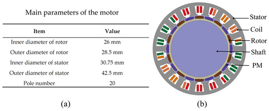
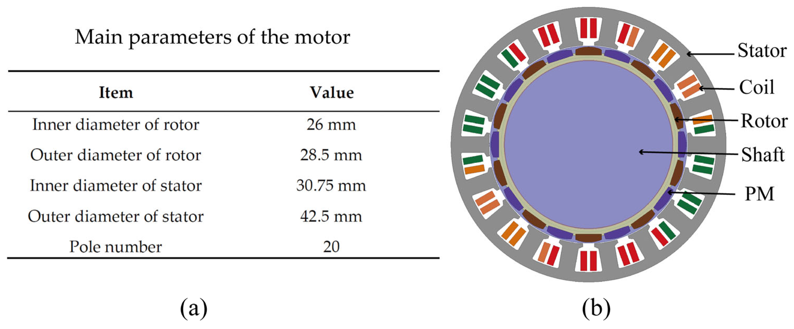
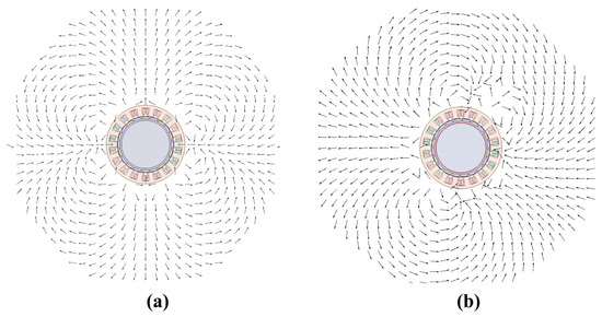
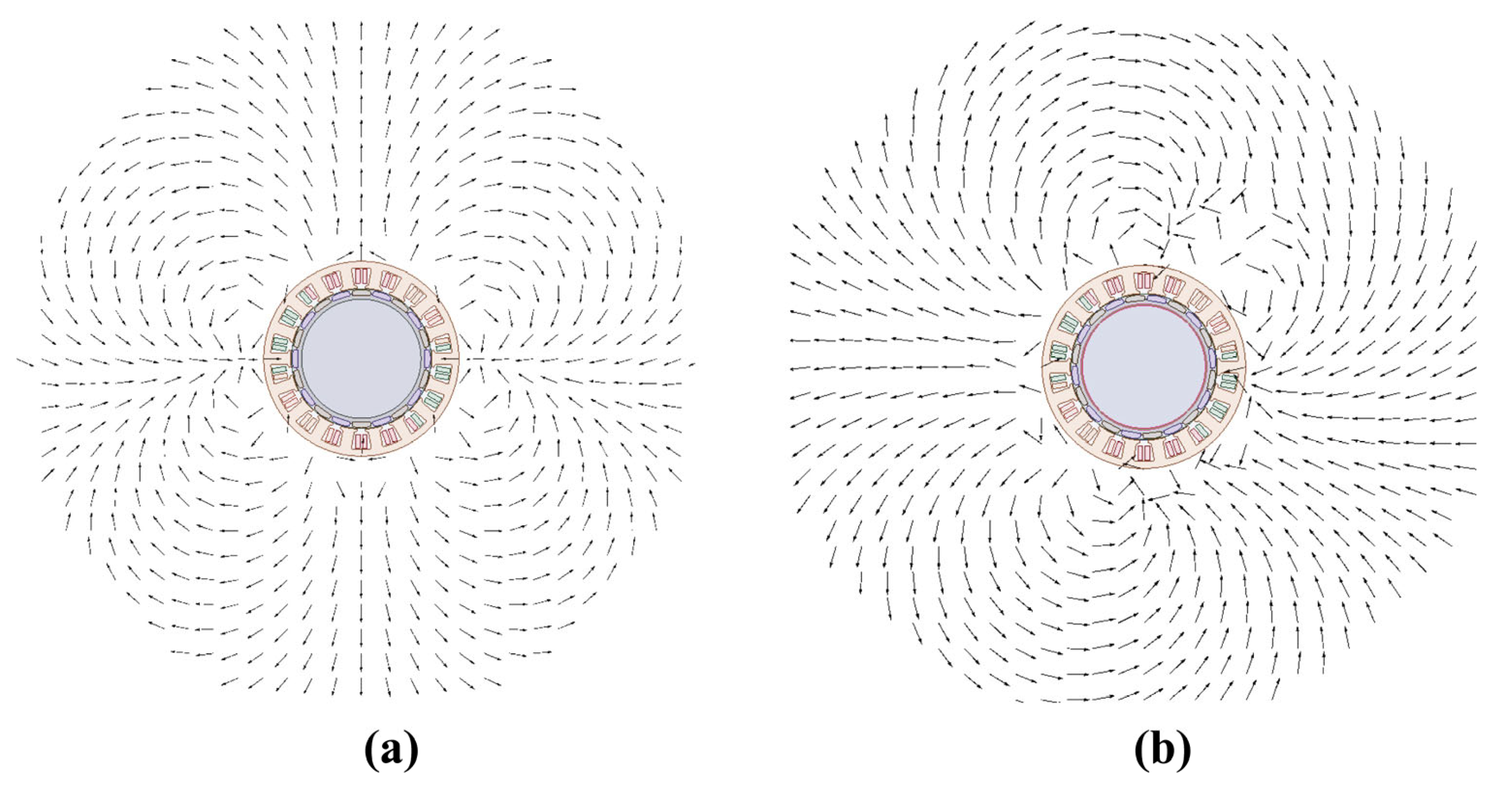
Figure 1 presents the main parameters and cross-sectional structure of the motor, and Figure 2 shows the leakage flux distribution of the motor. The basic model consists of ten pole pairs of permanent magnets embedded in the rotor and excitation windings mounted on the stator. When the magnetic field generated by the windings couples with that of the permanent magnets, an electromagnetic torque is produced, driving the motor into rotation. The permanent magnets provide a magnetic field that rotates with the rotor, while the stator windings generate a time-varying field driven by the alternating current. Accordingly, these two field sources are modeled and calculated separately.
Figure 1.
Main parameters and cross-sectional structure of the motor: (a) main parameters; (b) cross-sectional structure of the motor.
Figure 2.
Leakage flux distribution in motor: (a) static open-circuit condition; (b) rotating no-load condition.
2.2. Magnetic Properties of Shielding Materials
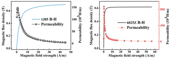
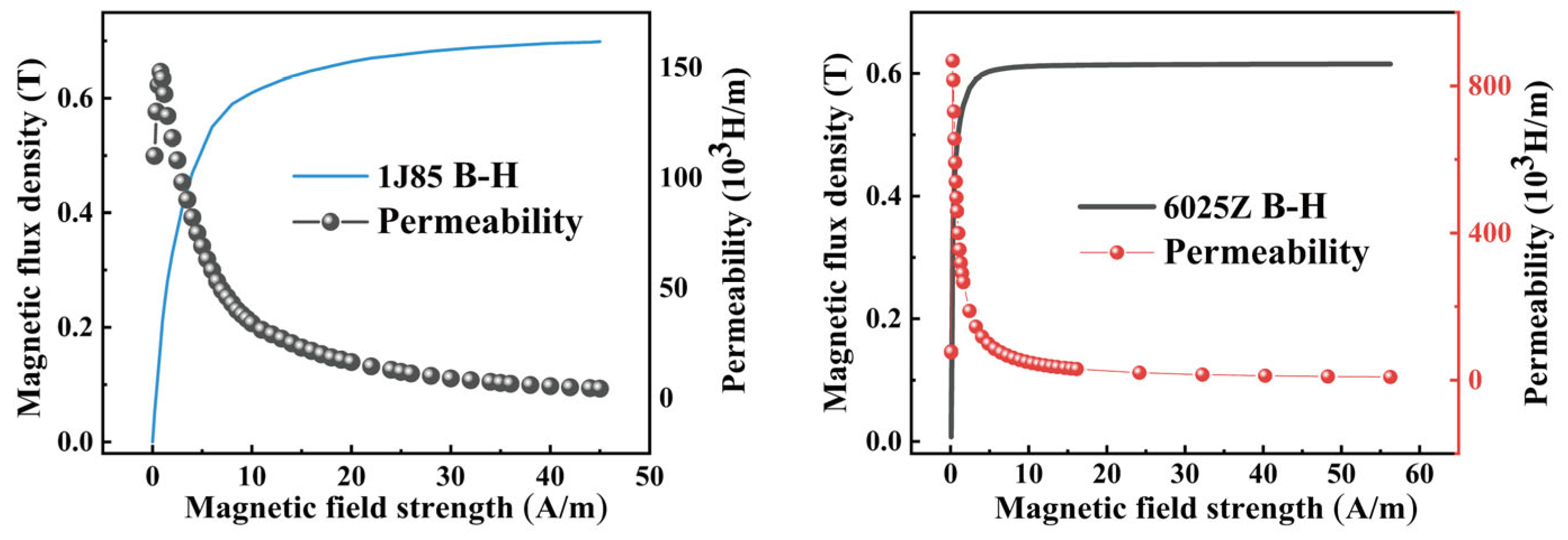
The magnetic properties of the Co-based amorphous alloy (6025Z) ribbon are compared with those of conventional 1J85 permalloy in Figure 3, and the corresponding key parameters are summarized in Table 1. The 6025Z ribbon exhibits a significantly higher initial permeability (μi = 6 × 10⁵) and maximum permeability (μmax = 8.6 × 10⁵) than 1J85, whose corresponding values are μi = 6 × 10⁵ and μmax = 1.48 × 10⁵ This indicates that 6025Z is more effective in providing a low-reluctance path for low-frequency leakage flux. Although its saturation flux density (Bs = 0.62 T) is slightly lower than that of 1J85 (0.68 T), its much smaller thickness makes it more suitable for multilayer lamination and compact shielding structures. Therefore, considering both magnetic properties and structural adaptability, 6025Z was selected as the shielding material in this study.
Figure 3.
Comparison of the magnetic properties of 1J85 permalloy and 6025Z Co-based amorphous ribbon: B–H curves and permeability variation with magnetic field strength.
Table 1.
Magnetic properties of amorphous ribbons.
2.3. Analytical Model
In accordance with magnetostatic theory, the shielding structure of the motor is characterized by the absence of free currents, with the magnetic field primarily influenced by the spatial distribution of magnetic materials and the imposed boundary conditions. In such current-free regions, the magnetic field can be effectively described using the magnetic scalar potential, rather than the magnetic vector potential. This approach simplifies the analysis of the shielding region, significantly reducing computational complexity and providing an efficient means for modeling static magnetic fields in non-conductive structures.
The basic equations governing the magnetic scalar potential are summarized as follows. In a current-free region, the magnetic field can be expressed using the scalar potential formulation as
The magnetic field can be expressed in terms of a scalar magnetic potential Vm as
using the constitutive relation
and combining with
Accordingly, the governing equation for the magnetic scalar potential can be written as
where Br is the remanent flux density, μ0 indicates the permeability of vacuum, and μrec is the relative permeability of the medium [35,36].
Along the exterior boundaries, the magnetic field is tangential to the boundary surface, as the magnetic flux lines form closed loops around the magnet. Accordingly, the natural boundary condition derived from the magnetic scalar potential equation can be expressed as
where n denotes the unit normal vector to the boundary surface. This condition ensures that the magnetic flux does not penetrate the exterior boundaries, maintaining continuity of the magnetic field within the computational domain [37].
The relative permeability μrec of the amorphous alloy shielding layer is determined from the measured B-H characteristics. For the nonlinear magnetic response, the differential permeability is defined as
while in the saturation region, the relation
is adopted to extrapolate the B-H curve and obtain the corresponding variation of μrec [38].
The validation of the equivalent model involves two magnetic property definitions: μrec representing the linear relative permeability and the magnetization curves (MCs) representing the nonlinear magnetic characteristics of the amorphous materials.
The analytical expression for magnetic shielding efficiency is defined as
where Bex denotes the flux density magnitude without shielding and Bin represents the internal flux density magnitude at the identical spatial point with the shield deployed.
2.4. Magnetic Shielding Structure
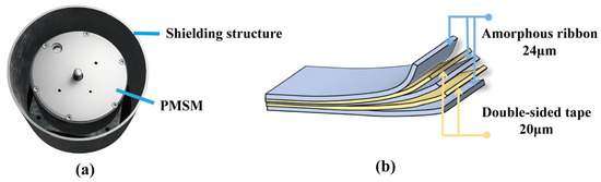
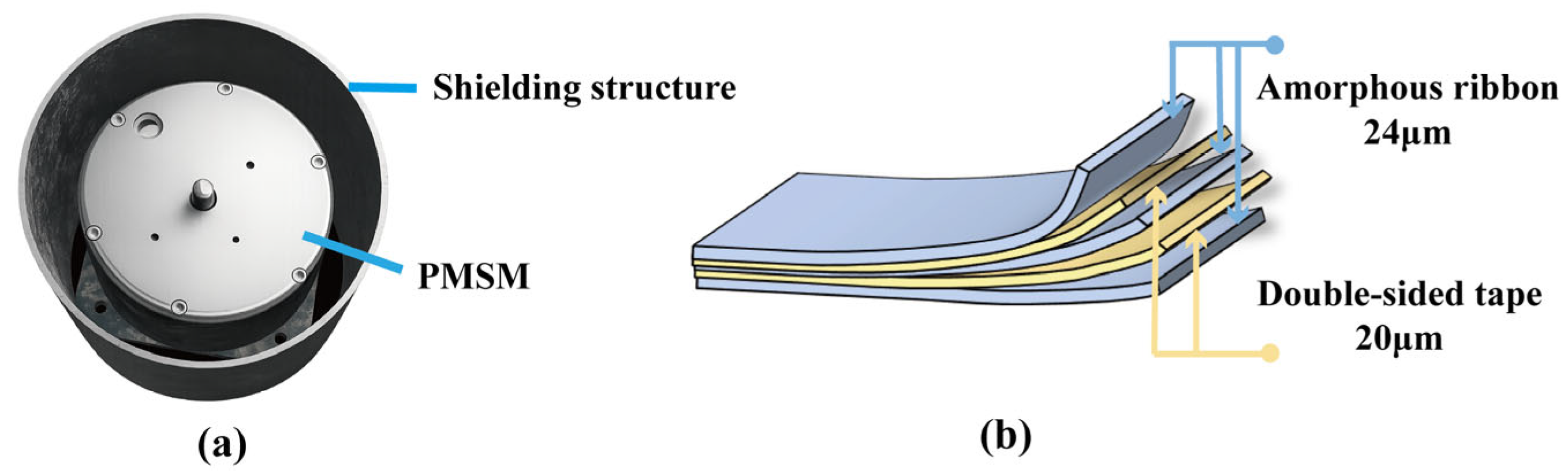
Based on the material characterization presented in the previous subsection, the shielding structure is described as follows. To investigate the application of thin magnetic shielding structures in suppressing the external stray magnetic field of the motor, a cylindrical shielding structure based on Co-based amorphous ribbons was designed, as shown in Figure 4. Figure 4a presents the motor shielding structure, while Figure 4b presents the multilayer amorphous ribbon shielding structure. The shield was mounted coaxially outside the PMSM to form a barrel-type enclosure, thereby ensuring a consistent structural configuration for subsequent analysis and testing.
Figure 4.
Shielding structure: (a) motor shielding structure; (b) multilayer amorphous ribbon shielding structure.
Co-based amorphous ribbons possess high magnetic permeability, small thickness, and good adaptability to laminated assembly, making them suitable for the design of low-frequency magnetic shielding structures for motors. Based on the single-layer structure, a multilayer shielding configuration composed of alternating Co-based amorphous ribbon layers and adhesive interlayers was further developed, as shown in Figure 4b. While ensuring structural integrity and practical assemblability, this design increases the effective shielding thickness and provides a structural basis for enhancing the suppression of the external stray magnetic field of the motor.
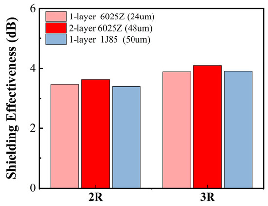
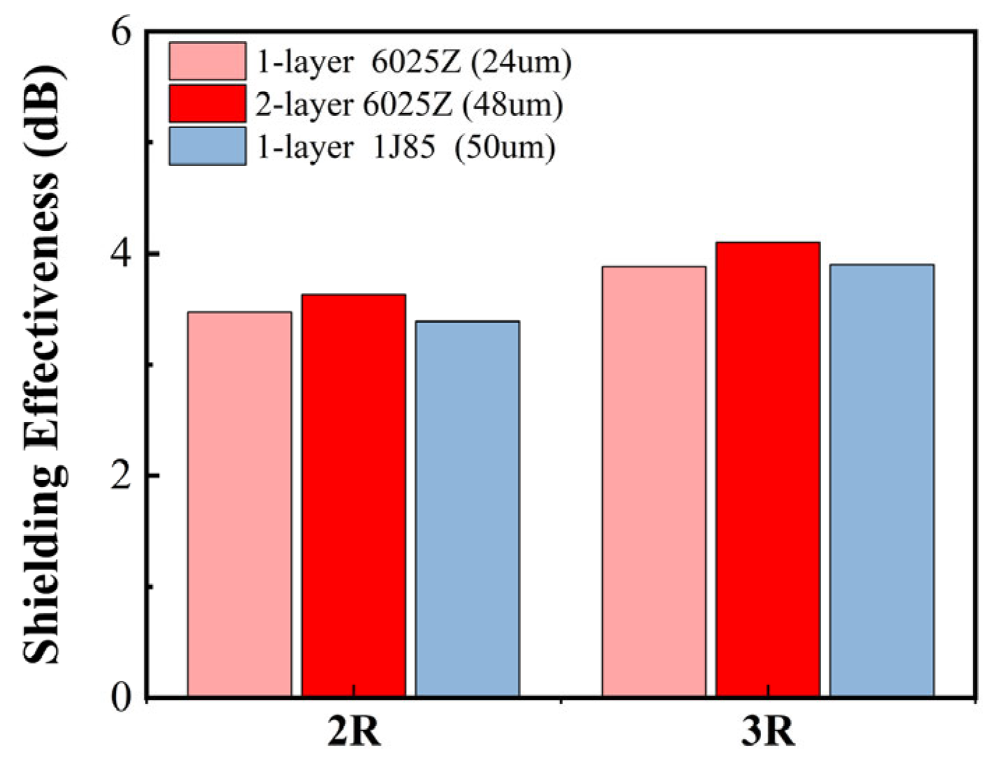
To compare the suppression capability of different shielding materials for the external stray magnetic field of the motor under similar thickness conditions, three cylindrical shielding structures were designed and fabricated, including a single-layer 6025Z ribbon (24 μm), a double-layer 6025Z ribbon (48 μm), and a single-layer 1J85 permalloy sheet (50 μm), as shown in Figure 5. All shielding structures were installed coaxially outside the PMSM to form a barrel-type enclosure, so that the testing conditions remained consistent and the results were directly comparable. The experiments were carried out inside the shielding barrel. Magnetic flux density was measured at different positions away from the motor outer surface before and after installing each shielding material, and the corresponding shielding effectiveness (SE) was then calculated to evaluate the suppression performance of different materials against the external leakage field.
Figure 5.
Comparison of the shielding performance between 1J85 and 6025Z.
It can be seen from Figure 5 that the shielding effectiveness of all three shielding structures gradually increases as the measurement distance increases. Among them, the two-layer 6025Z (48 μm) structure consistently exhibits the best performance at all measurement points. At 2R, its shielding effectiveness reaches 3.63 dB, which is higher than that of the single-layer 6025Z (3.47 dB) and the single-layer 1J85 (3.39 dB). This indicates that, under comparable thickness conditions, the two-layer 6025Z structure provides better overall shielding performance than 1J85, and that increasing the number of 6025Z layers can further enhance stray-field suppression.
2.5. Simplified Model Simulation Methodology
Based on the above shielding structure design and material selection, we established two shielding models with identical external geometry: a refined model (R-model) and a simplified model (S-model). The R-model explicitly includes the amorphous ribbon layers and the insulating adhesive layers between adjacent ribbons, and its simulation results are taken as the reference benchmark. In contrast, the S-model neglects the lamination details and represents the ribbon assembly as a homogenized continuum, while maintaining the same outer dimensions as the R-model. To simplify the description of the laminated structure, both the magnetization-curve method and the equivalent-permeability method were adopted in this study. The magnetization curve was obtained experimentally using a DC hysteresis loop tracer, while the equivalent permeability was determined based on a series magnetic reluctance model [39,40]. For the laminated structure composed of alternating magnetic ribbon layers and adhesive layers, the total magnetic reluctance can be expressed as
where tm is the thickness of the magnetic ribbon, μrec is the relative permeability of the magnetic ribbon, A is the equivalent magnetic flux cross-sectional area, ta is the thickness of the adhesive layer, μ0 indicates the permeability of vacuum, and μa is the relative permeability of the adhesive layer and is assumed to be approximately 1. The total equivalent thickness is defined as
A proportional factor F is further introduced as
Then, the equivalent relative permeability of the laminated structure can be written as
Considering that the magnetic flux conduction characteristics of the laminated structure are direction-dependent, the equivalent permeabilities in different directions can be further expressed as
μeq,z denotes the equivalent relative permeability in the direction normal to the laminated layers, whereas μeq,x and μeq,y denote the equivalent relative permeabilities in the directions parallel to the laminated layers.
Because the amorphous ribbons are extremely thin and the permeability of the adhesive interlayers is close to that of air, magnetic flux in the direction normal to the ribbon plane must continuously pass through multiple low-permeability adhesive layers. This leads to a large magnetic reluctance in the thickness direction and thus a significantly reduced equivalent relative permeability μeq,z. In contrast, magnetic flux parallel to the ribbon plane mainly propagates within the high-permeability amorphous ribbons and is only weakly affected by the adhesive layers, so the equivalent relative permeabilities μeq,x and μeq,y remain relatively high. Therefore, the multilayer amorphous ribbon structure exhibits pronounced anisotropic magnetic conduction characteristics, meaning that the magnetic field tends to distribute more easily along the ribbon plane rather than penetrate through the thickness direction.
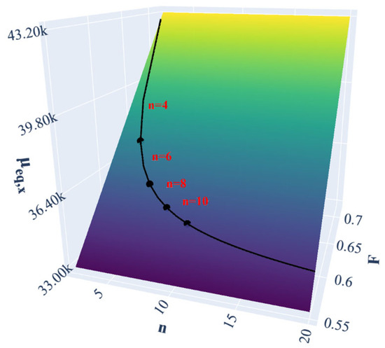
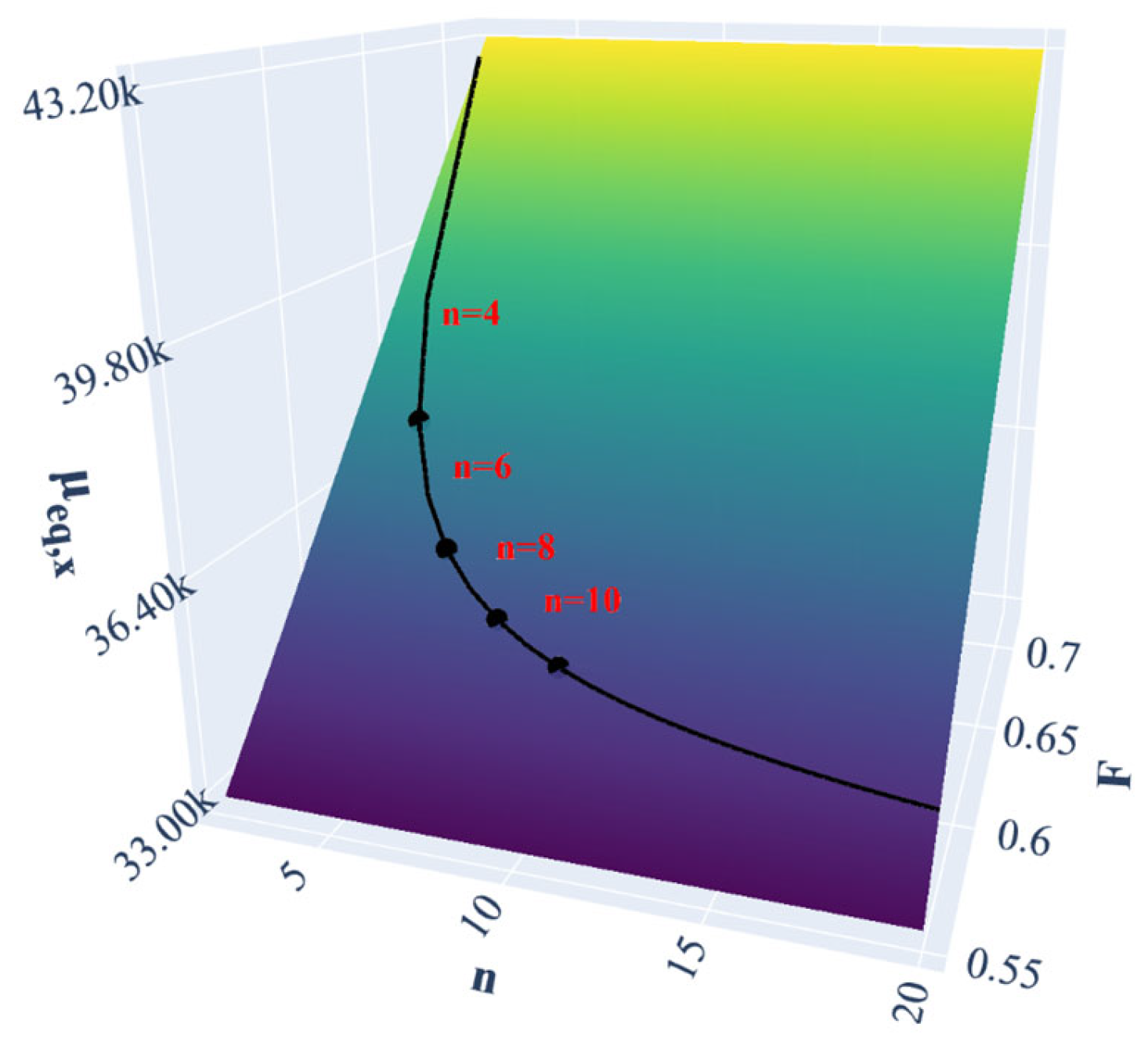
Figure 6 shows the variation of the tangential equivalent relative permeability with the layer number and the magnetic material volume fraction , where is calculated by substituting the material parameters into the equivalent-permeability expression, with for the magnetic ribbon. The colored surface represents the theoretical variation trend of μeq,x under different combinations of and , while the black curve denotes the design trajectory of the laminated structure as the layer number changes, reflecting the evolution of the equivalent permeability corresponding to the variation of F with n. The black dots on the curve indicate the values at several representative layer numbers, and the red labels n = 4, 6, 8, and 10 correspond to the positions of these representative cases. It can be seen that μeq,x increases with increasing F, indicating that a higher proportion of magnetic material is beneficial for enhancing the in-plane magnetic conduction capability of the laminated structure. However, along the laminated design trajectory adopted in this study, the increasing proportion of the adhesive layer causes a slight decrease in F as n increases, leading to a gradual decrease in μeq,x. When the layer number approaches 10, the decreasing trend becomes relatively moderate, while a relatively high effective permeability can still be maintained, indicating a reasonable compromise between shielding performance and layer utilization efficiency. From the viewpoint of fabrication, the amorphous ribbon becomes brittle after annealing, and an excessive number of layers may increase the risk of cracks and damage during wrapping and assembly. Compared with configurations with more layers, the 10-layer structure exhibits a more uniform stress distribution during lamination and assembly, resulting in a lower probability of fracture and improved structural consistency and reliability. Therefore, considering both electromagnetic performance and practical manufacturability, 10 layers were selected for the subsequent shielding structure design. The corresponding two-dimensional motor shielding models of the 10-layer R-model and S-model are shown in Figure 7.
Figure 6.
Effects of layer number and proportional factor on the equivalent permeability of the laminated amorphous ribbon structure.
Figure 7.
Analytical model: (a) refined model (R-model); (b) simplified model (S-model).
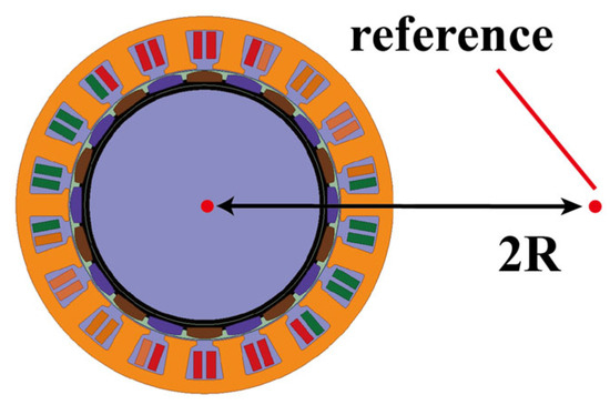
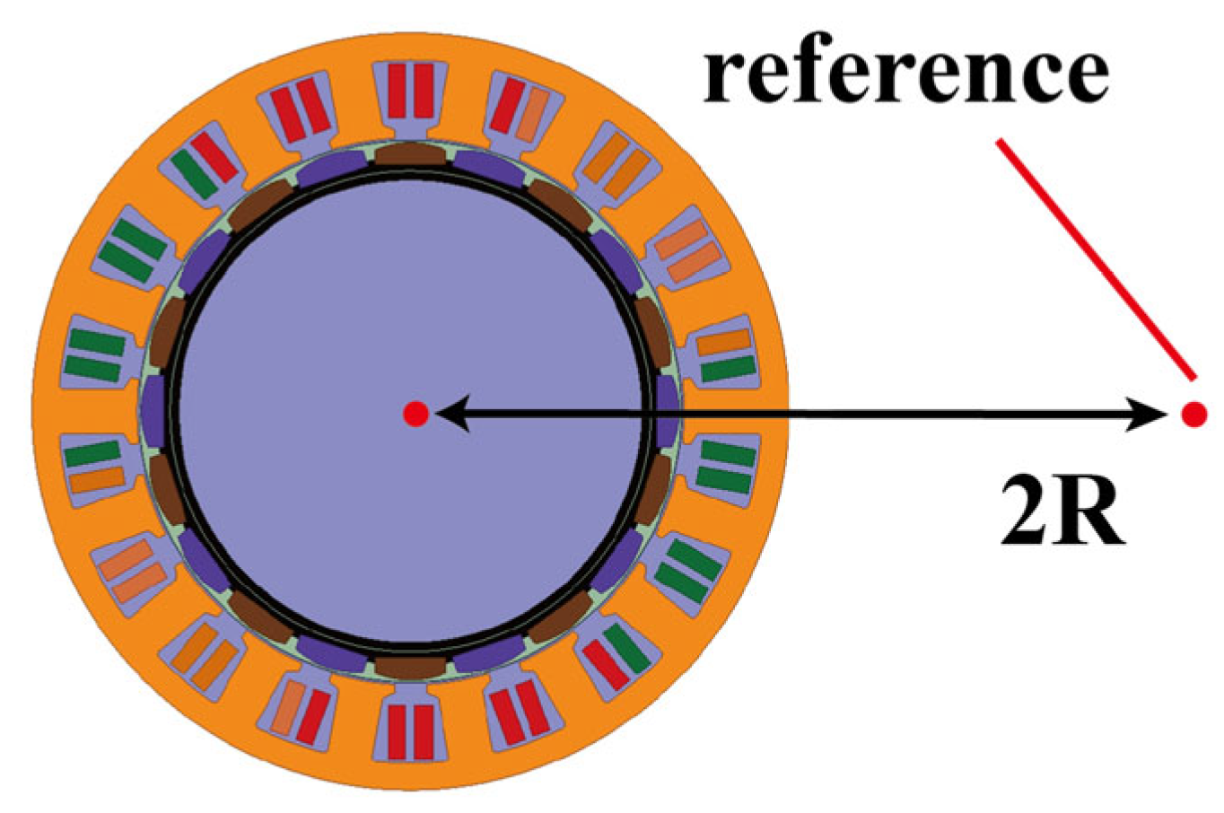
To ensure consistency in shielding effectiveness evaluation and preserve the model’s predictive accuracy in critical regions, this study evaluates the magnetic field strength at a reference point located at twice the source radius (Figure 8). This approach aligns the validation with experimental measurement methods and effectively captures model accuracy across the spatial scales relevant to shielding performance. The experiment was conducted inside the shielding chamber under static conditions. After the motor surface was covered with the shielding layer, a three-axis fluxgate sensor (Mag-13, Bartington Instruments, Witney, Oxfordshire, UK) was placed at twice the motor radius (2R) from the surface to measure the magnetic field, and the obtained data were compared with the simulation results for validation. In the simulations, the shielding structure was defined using two material models (relative permeability (μrec) and the initial magnetization curve (MC)) to evaluate the shielding performance, predictive accuracy and computation time. All calculations were conducted under a 2-D framework, and the comparative error analysis between the two approaches was used to assess whether the simplified model could be reliably extended to 3-D simulations.
Figure 8.
Reference point for simulation validation of different models (R denotes the motor radius).
2.6. Results and Discussion
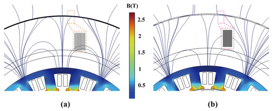
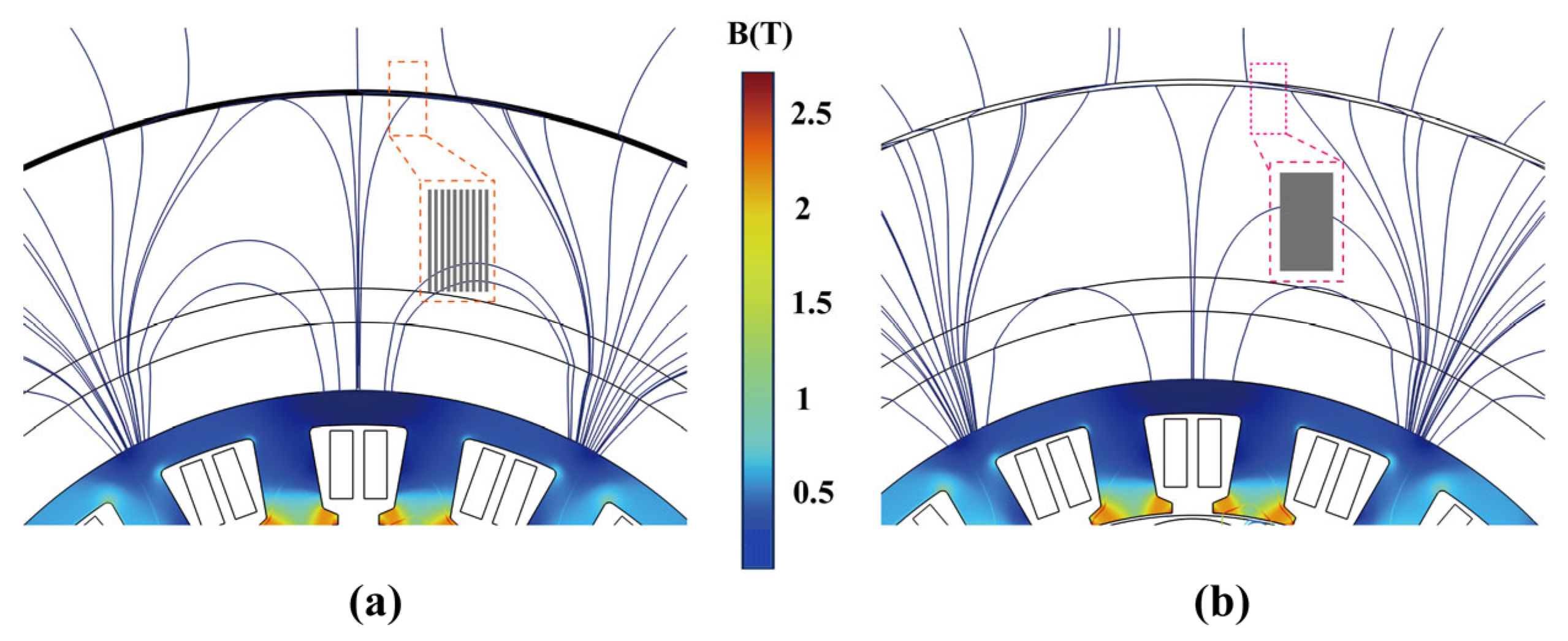
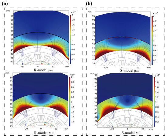
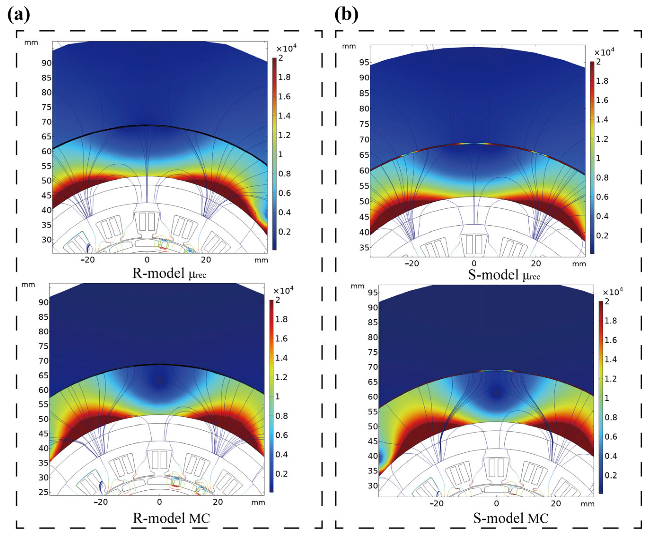
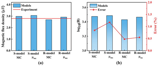
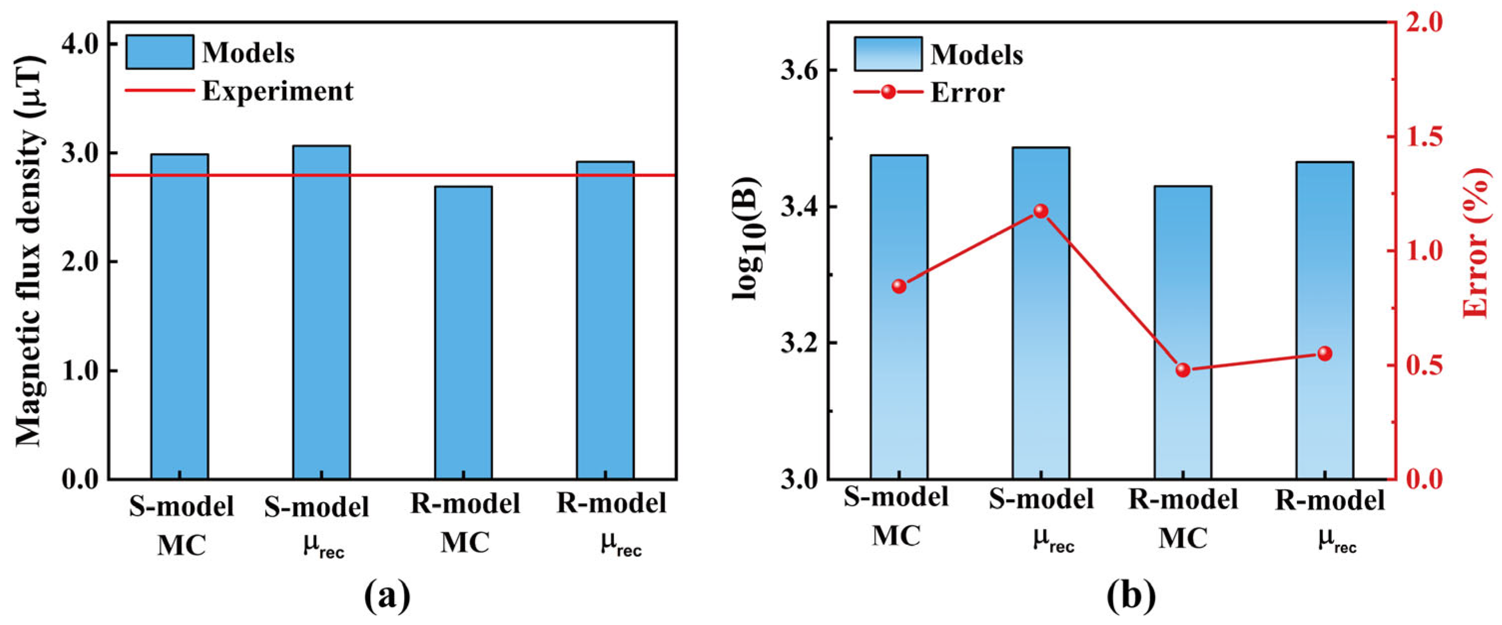
As can be observed from the upper field distribution within the 2R circular region in Figure 9, the S-model (Figure 9a) reproduces the remanence pattern of the R-model (Figure 9b) with high consistency, whereas the R-model exhibits slightly lower remanence in the external region outside the shield. Under identical conditions, the magnetic field calculated with relative permeability is slightly higher than with the magnetization curve. The remanence at the reference point with experimental data (Figure 10a) reveals only minor discrepancies between the two models. The R-model, based on magnetization curves, aligns more closely with the experimental results, while the S-model shows only slight differences. To align with the earlier definition of shielding effectiveness (SE), we express magnetic flux density here as lg(B). This logarithmic format clearly showcases attenuation characteristics and enables straightforward comparisons of simulation and experimental data. As Figure 10b shows, the slight 1.17% deviation in log10(B) between models and the experiments indicates the negligible effect of modeling simplification on shielding efficiency assessments. Furthermore, Table 2 highlights the critical role of computational efficiency in large-scale finite element simulations. The S-model cut computation time by about 28% over the R-model, significantly enhancing simulation efficiency. Therefore, the S-model provides a reasonable balance between computational efficiency and prediction accuracy, making it suitable for subsequent 3-D simulations.
Figure 9.
Comparison of remanence distribution between R-model and S-model using different simulation methods: (a) using μrec; (b) using MC.
Figure 10.
Comparison between the two simulation methods and experimental results for the R-model and S-model: (a) simulated and measured remanence distributions; (b) comparison of log10(B) between models and experiment, together with the relative errors.
Table 2.
Simulation time-saving rate between S-model and R-model.
It should be noted that the proposed equivalent model is intended as an efficient engineering approximation for laminated amorphous ribbon shields. Although the anisotropic magnetic response of the layered structure is represented through direction-dependent equivalent relative permeabilities, the model still neglects the detailed layer-by-layer geometry and therefore cannot fully reproduce local field distortion, interlayer effects, or end-region three-dimensional leakage behavior. As a result, its prediction accuracy may decrease in regions with strong magnetic-field gradients, pronounced edge effects, or severe material nonlinearity. Nevertheless, for the macroscopic evaluation of PMSM external stray-field suppression, the model provides a reasonable compromise between computational efficiency and acceptable accuracy.
3. 3D FEM and Experimental Validation Model
3.1. 3D FEM and Experimental
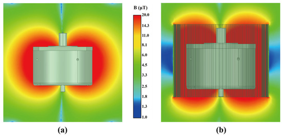
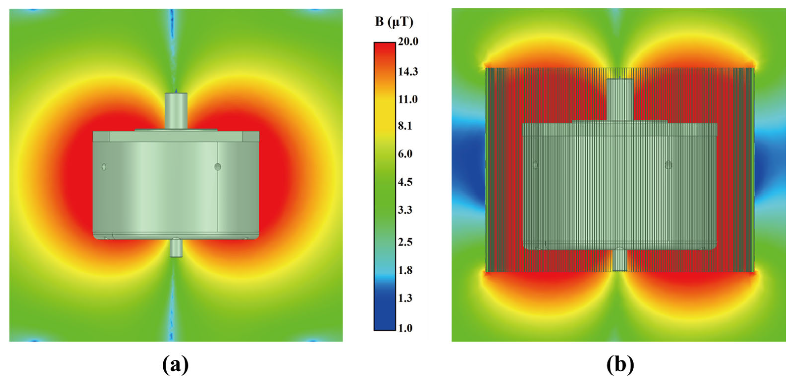
To further validate the above analysis, the corresponding 3-D simulation and experimental results are presented in this section. A 3-D model incorporating the simplified shielding structure was established to evaluate the distribution of the motor stray magnetic field. Figure 11a,b show the static 3-D magnetic flux density distributions under unshielded and shielded conditions, respectively. After the introduction of the shielding layer, which is represented in the simplified model by an equivalent structure corresponding to ten laminated amorphous ribbons with a total thickness of 420 μm, the axial leakage field of the motor is noticeably reduced, and the magnetic flux is more effectively confined within the motor housing.
Figure 11.
3D magnetic flux distribution in motor: (a) unshielded condition; (b) shielded condition.
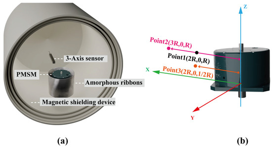
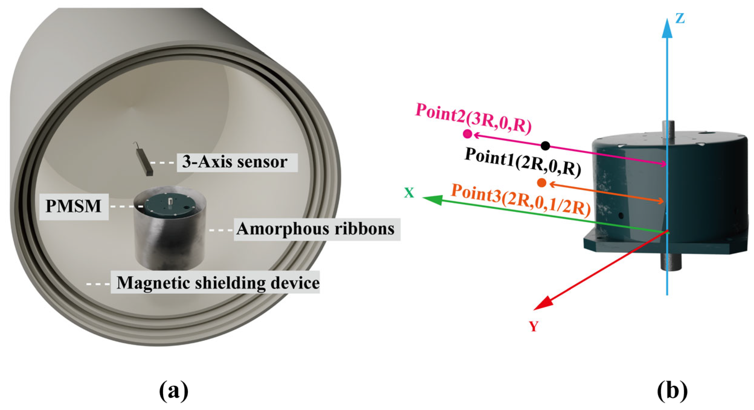
To validate the simplified model, a dedicated experimental platform was constructed, as shown in Figure 12a. The magnetic shielding structure was prepared by sequentially laminating amorphous ribbons onto a 3D-printed nonmagnetic support, with neighboring layers bonded by 20 μm thick double-sided adhesive. The adhesive comprised a transparent PET carrier coated with acrylic layers on both sides, thereby providing mechanical integrity without introducing noticeable magnetic interference. Before each test, both the shielding cylinder and the shielding structure were demagnetized using a handheld demagnetizer to eliminate residual magnetization and ensure a stable initial magnetic state. The external magnetic field was measured using a three-axis fluxgate sensor (Mag-13, Bartington Instruments, UK). Prior to measurement, the sensor was preheated and calibrated to improve signal stability and measurement reliability. The sensor operates based on the nonlinear magnetization and periodic saturation of an internally excited high-permeability core, enabling the detection of weak external magnetic fields. The experiments were conducted under static and no-load rotating conditions to reduce the influence of eddy-current effects caused by the conductivity of the amorphous ribbons. During measurement, the PMSM with the laminated shielding structure was placed inside the shielding cylinder, and the magnetic flux density was recorded at three reference points, i.e., Point 1 (2R, 0, R), Point 2 (3R, 0, R), and Point 3 (2R, 0, ½R); as indicated in Figure 12b, Points 1 and 2 are located at the same axial position but at different radial distances from the motor, and are therefore used to evaluate the radial attenuation behavior of the external stray magnetic field. Point 3 is located at the same radial distance as Point 1 but at a different axial position, and is used to reflect the axial variation of the stray field. In this way, the three points jointly characterize the radial and axial distribution features of the 3-D external magnetic field, providing representative locations for simulation–experiment comparison. To ensure positional consistency and measurement repeatability, the sensor was elevated and fixed using a nonmagnetic supporting fixture, so that the probe remained stably positioned at the designated locations while minimizing disturbance to the local magnetic field. Each test was maintained for 1 min, and the time-averaged value was used for subsequent analysis; all measurements were conducted inside the shielding barrel to minimize interference from external magnetic fields and other environmental disturbances. Although experimental error could not be completely eliminated, its influence was reduced through careful control of the test procedure and experimental conditions. Specifically, sensor-related error was minimized by preheating and calibrating the fluxgate sensor before measurement to reduce zero drift and output fluctuation; positioning error was reduced by fixing the probe with a nonmagnetic fixture to ensure that the probe center coincided with the target coordinates; the influence of background magnetic-field fluctuation was mitigated by performing the test in a magnetically shielded environment and demagnetizing both the shielding cylinder and the shielding structure before measurement; and the installation error of the shielding structure was reduced by adopting a consistent mounting procedure. The measured results were then compared with the simulation results to assess the shielding performance and further verify the validity of the equivalent single-layer model. To quantitatively assess the deviation between the simulated and experimentally measured shielding effectiveness, the relative error was defined as follows:
where SEsim and SEexp denote the simulated and experimentally measured shielding effectiveness, respectively, and δSE represents the relative error of shielding effectiveness.
Figure 12.
Experimental model: (a) shielding-performance test system; (b) measured points. Point 1 (2R, 0, R), Point 2 (3R, 0, R), and Point 3 (2R, 0, ½R).
3.2. Static Experimental Validation
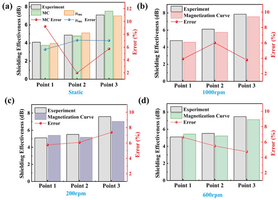
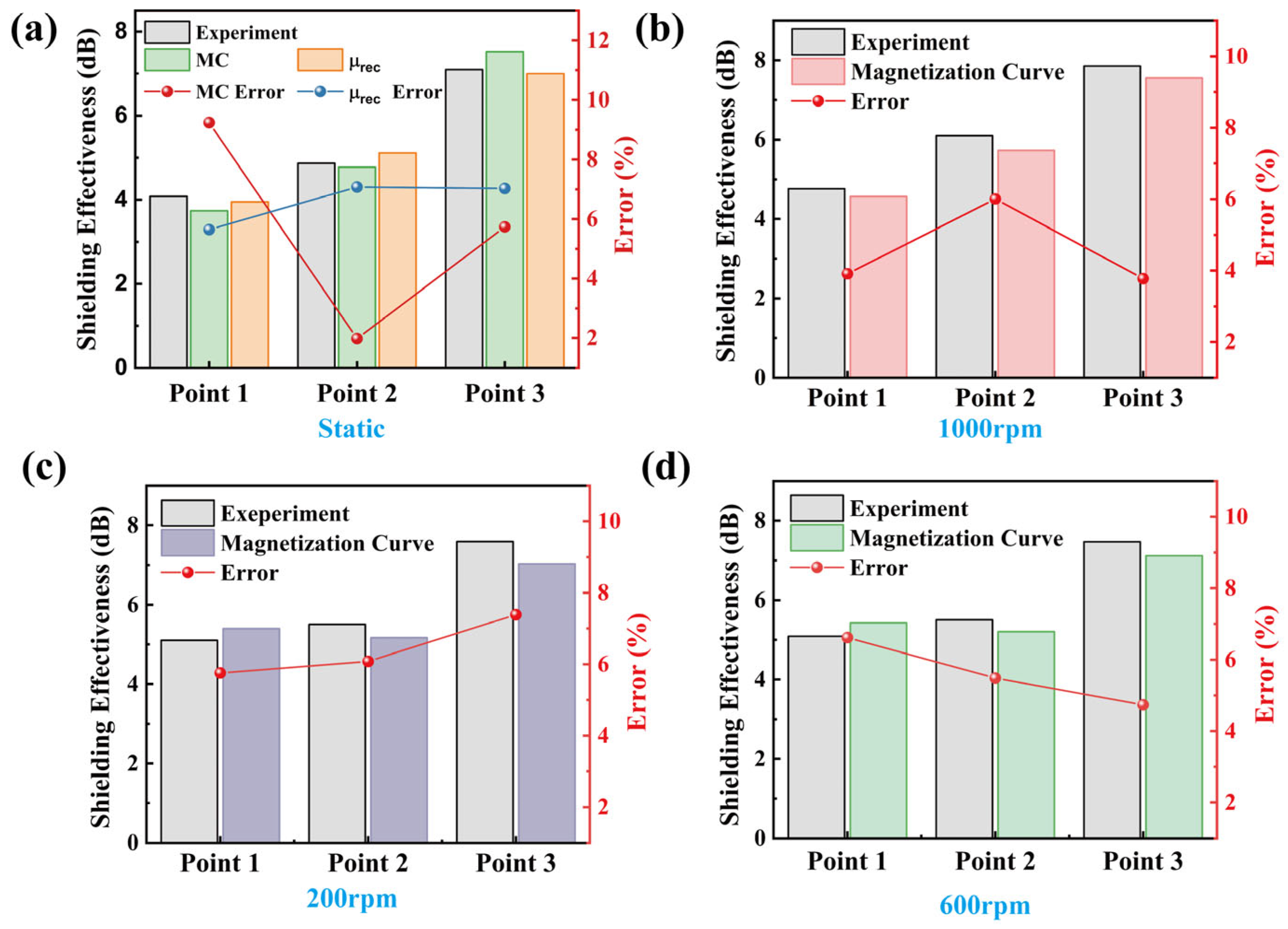
Based on the above experimental setup, the static shielding performance was first evaluated through a comparison between the measured and simulated results, as shown in Figure 13a. The results indicate that the error range of simulations based on the magnetization curve (MC) is 5.65–7.03%, whereas that of simulations using relative permeability (μrec) is 1.98–9.23%. Point 3 exhibited the best shielding performance, achieving a shielding effectiveness of 7.09 dB, as the magnetic field outside the motor housing decreased from 6076 nT to 2684 nT after shielding. Although both approaches capture the shielding performance well, the magnetization-curve-based method demonstrates superior stability in error levels.
Figure 13.
Comparison between experiment and simulated shielding effectiveness at three reference points under different operating conditions: (a) static open-circuit condition; (b) rotating no-load condition at 1000 rpm; (c) rotating no-load condition at 200 rpm; (d) rotating no-load condition at 600 rpm. The left vertical axis represents shielding effectiveness, while the right vertical axis represents the relative error defined by Equation (15).
Further analysis reveals that the shielding effect is more pronounced at the central region of the motor than at the ends, primarily due to stronger flux leakage near the edges. This observation agrees well with experimental results, confirming the reliability of the simulations and providing theoretical support for the design of shielding structures. Consequently, for subsequent simulations under no-load operating conditions, the magnetization curve was adopted as the modeling basis to ensure both accuracy and stability.
3.3. No-Load Condition Experimental Validation
Following the above static test procedure, the shielding performance under no-load operating conditions was further evaluated, with the motor operated at 1000 rpm with only minor fluctuations. At this speed, the corresponding electrical frequency was 166.6 Hz, calculated as for the 20-pole PMSM, and the motor was operated at 1000 rpm with only minor fluctuations. In the experiment, the remanence at each measurement point was recorded before and after the installation of the shielding structure. The data acquired during 1 min of continuous operation were then averaged to obtain the mean shielding efficiency. In the numerical simulation, the magnetic field distribution over two operating cycles was computed, and the corresponding shielding efficiency was calculated for comparison with the experimental results.
The comparison between the experimental measurements and numerical simulations at 1000 rpm is presented in Figure 13b. The results indicate that the simulation using the initial magnetization curve yields an error range of 3.77–6.01%, with the simulated shielding effectiveness being slightly lower than the measured values. Among the three measurement points, Point 3 exhibited the highest shielding effectiveness, reaching 7.85 dB, where the external magnetic field decreased from 6155 nT to 2492 nT after shielding. The slight underestimation in the simulations is mainly attributed to the modeling simplification in which the multilayer amorphous ribbon structure was represented by an equivalent single-layer thickness. This simplification inevitably reduces the fidelity of the magnetic response, particularly under dynamic excitation.
To further examine the applicability of the equivalent model under different dynamic operating conditions, additional comparative studies were performed at lower rotor speeds of 200 rpm and 600 rpm. The results, as shown in Figure 13c,d, indicate that the S-model maintains consistently good agreement with the experimental data, with the overall error remaining within 7.38% across all test conditions. At 200 rpm, where the magnetic field variation is relatively weak and the machine operates in a quasi-static regime, the minimum error is 5.75%. At 600 rpm, the minimum error decreases slightly to 5.48%, indicating improved consistency as the excitation frequency increases. A closer examination of the three measurement points further shows that Point 3 generally exhibits a higher shielding effectiveness than Points 1 and 2. This is mainly because Point 3 is located near the middle region of the shielding cylinder, corresponding to the axial central region of the motor, where the shielding layer provides a more continuous high-permeability flux path for the stray magnetic field. As a result, the magnetic flux is more effectively confined in this region, leading to a faster decay of the external magnetic field after shielding is applied. By contrast, Points 1 and 2 are closer to the end or transition regions, where end effects are more pronounced and magnetic flux tends to spread outward more easily. Therefore, the relatively distinct tendency observed at Point 3 is physically reasonable, as it reflects the axial distribution characteristics of the motor stray field and the enhanced shielding action in the middle region, rather than an anomalous result.
These results demonstrate that the proposed equivalent model provides reliable predictions of shielding performance across both static and dynamic conditions, confirming its robustness and suitability for practical external-field shielding analysis and design.
4. Conclusions
This study investigated the external leakage magnetic field characteristics of a permanent magnet synchronous motor and developed an efficient equivalent modeling method for multilayer amorphous ribbon shielding structures. Based on the distinct radial and axial stray-field distributions revealed by the 2-D and 3-D analyses, a compact high-permeability multilayer amorphous ribbon shield was designed for external magnetic shielding under limited installation space. To overcome the high computational cost associated with the explicit modeling of multiple ultrathin layers, an equivalent single-layer model was established and systematically validated. The results demonstrate that the proposed method can preserve shielding accuracy while significantly improving computational efficiency, thereby providing an effective tool for the analysis and design of compact PMSM magnetic shielding structures. The main conclusions are as follows:
- The 2-D and 3-D simulations revealed distinct radial and axial distribution characteristics of the motor stray magnetic field, which provided the basis for the design and evaluation of the external shielding structure.
- Considering the space constraints of practical applications, a multilayer amorphous ribbon shield with high permeability was proposed. The results further showed that, under comparable thickness conditions, amorphous ribbons exhibit better overall shielding performance than 1J85 permalloy, indicating clear advantages for PMSM stray-field suppression.
- An equivalent single-layer model was developed for the multilayer ultrathin shielding structure. Its validity was verified under both constant relative-permeability and nonlinear magnetization-curve descriptions. The maximum deviation in log10(B) between the equivalent model and the refined multilayer model was less than 1.2%, demonstrating that the proposed simplification can accurately reproduce the macroscopic shielding response.
- The 2-D comparative results showed that the proposed equivalent model can effectively reduce the mesh density in the shielding region and shorten the computation time by up to 28% while maintaining acceptable accuracy. This confirms its advantage in improving computational efficiency for multilayer shielding analysis.
- Further 3-D simulation and experimental comparisons under static and rotating no-load conditions showed that the proposed model can accurately predict the shielding performance of the motor shielding structure, with errors ranging from 3.77% to 7.38%. These results verify the feasibility and reliability of the proposed method for practical PMSM shielding analysis.
- Overall, the proposed equivalent modeling framework provides a reasonable balance between accuracy and efficiency, and offers practical guidance for the rapid evaluation and optimization of stray-field shielding structures in compact PMSM systems.
Future work will focus on extending the proposed method to more complex operating conditions, including load conditions and more pronounced three-dimensional field variations, as well as further improving the equivalent model for stronger material nonlinearity and end-region effects. In addition, the optimization of shielding materials and structural configurations for practical compact PMSM systems will also be investigated.
Author Contributions
Conceptualization, J.L. and H.M. methodology, X.L.; software, B.L.; validation, H.M., B.L. and Y.L.; formal analysis, B.L.; investigation, A.H.; resources, Y.D.; data curation, B.L.; writing—original draft preparation, B.L.; writing—review and editing, X.L.; visualization, Q.M.; supervision, Q.M.; project administration, Q.M.; funding acquisition, J.L. All authors have read and agreed to the published version of the manuscript.
Funding
This research was funded by the National Natural Science Foundation of China (No. 52401222), Zhejiang Provincial Natural Science Foundation (LQN25E010011), and Ningbo Natural Science Foundation (2024J073, 2025Z017).
Data Availability Statement
The data presented in this study are available on request from the corresponding author. The data are not publicly available due to confidentiality restrictions associated with the experimental measurements, simulation models, and ongoing research project.
Acknowledgments
The authors would like to express their sincere gratitude to the Ningbo Institute of Materials Technology and Engineering, Chinese Academy of Sciences, Ningbo, Zhejiang, for providing research support and experimental conditions. The authors also acknowledge the support of the power quality signal generation and acquisition platform used in the experimental verification.
Conflicts of Interest
The authors declare no conflicts of interest.
References
- Zhang, Y.; McLoone, S.; Cao, W.; Qiu, F.; Gerada, C. Power Loss and Thermal Analysis of a MW High-Speed Permanent Magnet Synchronous Machine. IEEE Trans. Energy Convers. 2017, 32, 1468–1478. [Google Scholar] [CrossRef] [Scilit]
- Ruan, G.-Q.; Su, Y.-Y.; Cao, J.-L.; Su, Y.-H.; Gong, Z.-D.; Hu, X. Position Tracking Control of Permanent Magnet Synchronous Motor Based on AHONFTSMC Control. J. Electr. Eng. Technol. 2025, 20, 389–401. [Google Scholar] [CrossRef] [Scilit]
- Zhang, Y.; Xu, D.; Liu, J.; Gao, S.; Xu, W. Performance Improvement of Model-Predictive Current Control of Permanent Magnet Synchronous Motor Drives. IEEE Trans. Ind. Appl. 2017, 53, 3683–3695. [Google Scholar] [CrossRef] [Scilit]
- Xia, X.; Zhang, B.; Li, X. High Precision Low-Speed Control for Permanent Magnet Synchronous Motor. Sensors 2020, 20, 1526. [Google Scholar] [CrossRef] [Scilit] [PubMed]
- Lee, J.; Seo, W.; Ro, J. Analysis of an Anisotropic Permanent Magnet Synchronous Motor for Coreless Structure Implementation. J. Magn. 2025, 30, 141–149. [Google Scholar] [CrossRef] [Scilit]
- Yan, X.; Deng, W.; Wang, G.; Rasool, A.; Qi, S. Research on Novel Var Compensator Based on Dual-Rotary Phase-Shifting Transformers and Its Control Strategy. Int. J. Electr. Power Energy Syst. 2023, 144, 108632. [Google Scholar] [CrossRef] [Scilit]
- Fehn, P.; Kilian, L.; Karnapp, S.; Weigold, M. Life Cycle Assessment of Motor Spindles in Machine Tools—Comparison of SynRM and PMSM Spindles and Structural Lightweight Construction Measures. Procedia CIRP 2025, 135, 553–563. [Google Scholar] [CrossRef] [Scilit]
- Woloszyn, M.; Tarnawski, J. Magnetic Signature Reproduction of Ferromagnetic Ships at Arbitrary Geographical Position, Direction and Depth Using a Multi-Dipole Model. Sci. Rep. 2023, 13, 14601. [Google Scholar] [CrossRef] [Scilit]
- Huangfu, Y.; Wang, S.; Di Rienzo, L.; Zhu, J. Radiated EMI Modeling and Performance Analysis of a PWM PMSM Drive System Based on Field-Circuit Coupled FEM. IEEE Trans. Magn. 2017, 53, 1–4. [Google Scholar] [CrossRef] [Scilit]
- Momen, F.; Rahman, K.; Son, Y. Electrical Propulsion System Design of Chevrolet Bolt Battery Electric Vehicle. IEEE Trans. Ind. Appl. 2019, 55, 376–384. [Google Scholar] [CrossRef] [Scilit]
- Song, Z.; Liu, C.; Chen, Y.; Huang, R. Air-Gap Permeance and Reluctance Network Models for Analyzing Vibrational Exciting Force of In-Wheel PMSM. IEEE Trans. Veh. Technol. 2022, 71, 7122–7133. [Google Scholar] [CrossRef] [Scilit]
- Yin, Z.; Sui, Y.; Zheng, P.; Yang, S.; Zheng, Z.; Huang, J. Short-Circuit Fault-Tolerant Control Without Constraint on the D-Axis Armature Magnetomotive Force for Five-Phase PMSM. IEEE Trans. Ind. Electron. 2022, 69, 4472–4483. [Google Scholar] [CrossRef] [Scilit]
- Liu, T.; Fadel, M.; Li, J.; Ma, X. A MTPA Control Strategy for Mono-Inverter Multi-PMSM System. IEEE Trans. Power Electron. 2021, 36, 7165–7177. [Google Scholar] [CrossRef] [Scilit]
- Yao, A.; Sugimoto, T.; Odawara, S.; Fujisaki, K. Core Losses of a Permanent Magnet Synchronous Motor with an Amorphous Stator Core under Inverter and Sinusoidal Excitations. AIP Adv. 2018, 8, 056804. [Google Scholar] [CrossRef] [Scilit]
- Liu, C.; Zuo, S.; Wu, Z.; Chen, S.; Yin, B.; Zhuang, H.; Wang, S. Analytical Calculation of Magnetic Field and Electromagnetic Performance for Permanent Magnet Assisted Synchronous Reluctance Motors Considering Saturation Effect. IEEE Trans. Energy Convers. 2024, 39, 644–658. [Google Scholar] [CrossRef] [Scilit]
- Haq, M.A.U.; Farooq, H.; Liaqat, R.; Khan, Z.A.; Altamimi, A. A Novel Permanent Magnet Assisted Brushless Wound Rotor Synchronous Machine with Improved Torque Characteristics. IEEE Access 2025, 13, 124351–124363. [Google Scholar] [CrossRef] [Scilit]
- Meng, Q.; Wang, Z.; Lin, Q.; Ju, D.; Liang, X.; Xian, D. Theoretical Analysis of a Magnetic Shielding System Combining Active and Passive Modes. Nanomaterials 2024, 14, 538. [Google Scholar] [CrossRef] [Scilit]
- Rong, C.; Chen, M.; Wang, Q.; Yan, L.; Guo, Y.; Gao, H.; Wang, H.; Liu, X. Optimization Design of Hybrid Resonance-Based Passive Shielding Coils for Low-Electromagnetic Field Leakage and High Efficiency in WPT System. IEEE Trans. Ind. Electron. 2025, 72, 8757–8767. [Google Scholar] [CrossRef] [Scilit]
- Zhao, R.; Zou, J.; Xiao, L.; Liu, M.; Xu, Y. Design and Analysis of Special-Shaped Pole Piece PMSM with Low Vibration and High Overload Capacity. IEEE Trans. Appl. Supercond. 2024, 34, 1–4. [Google Scholar] [CrossRef] [Scilit]
- Lu, L.; Mao, Y.; Wang, X.; Jin, L.; Wang, Z. Maximum-Torque Optimization Control of Dual Three-Phase PMSM in Low-Frequency and Static Operations. IEEE J. Emerg. Sel. Top. Power Electron. 2023, 11, 5268–5527. [Google Scholar] [CrossRef] [Scilit]
- Xu, X.; Liu, W.; Huang, Y.; Li, W.; Che, S. Magnetic Shielding Mechanism and Structure Design of Composites at Low Frequency: A Review. J. Magn. Magn. Mater. 2023, 570, 170509. [Google Scholar] [CrossRef] [Scilit]
- Li, B.; Zhang, W.; Fu, W.; Xuan, F. Laser Powder Bed Fusion (L-PBF) 3D Printing Thin Overhang Walls of Permalloy for a Modified Honeycomb Magnetic-Shield Structure. Thin-Walled Struct. 2023, 182, 110185. [Google Scholar] [CrossRef] [Scilit]
- Choi, K.; Jung, C.; Yi, S. Improved Thermal Stability of FeNiCo-Based Nanocrystalline Soft Magnetic Alloys Enabled by Ni Segregation in the Amorphous Matrix. J. Alloys Compd. 2025, 1014, 178690. [Google Scholar] [CrossRef] [Scilit]
- Waeckerlé, T.; Demier, A.; Godard, F.; Fraisse, H. Evolution and Recent Developments of 80%Ni Permalloys. J. Magn. Magn. Mater. 2020, 505, 166635. [Google Scholar] [CrossRef] [Scilit]
- Zhao, C.; Li, N.; Liu, Q.; Wang, J. Enhanced Giant Magnetoimpedance Properties of Fe-Based Amorphous Ribbons by Coating Soft Magnetic Film. IEEE Trans. Magn. 2023, 59, 1–5. [Google Scholar] [CrossRef] [Scilit]
- Li, F.; Liu, Y.; Wang, R.; Li, J. Amorphous Precursor Strategy Enables High-Performance Ce-Substituted Nd-Fe-B Hot-Deformed Magnets. J. Rare Earths 2025, S1002072125004478. [Google Scholar] [CrossRef] [Scilit]
- Li, L.; Chen, J.; Zhang, X.; Han, Y.; Tian, Z.; Wu, X.; Eldeeb, H.H.; Kang, J.; Xu, G.; Zhao, H. Efficiency Characteristics of Loosely Coupled Transformer with Laminated Nanocrystalline Core Considering Nonlinear Factors Caused by Crushing and Compressing Process. IEEE Trans. Ind. Appl. 2024, 60, 8575–8584. [Google Scholar] [CrossRef] [Scilit]
- Xu, X.; Wang, L.; Liu, W.; Zhao, Z. Theoretical Modeling and Characterization of Equivalent Magnetic Properties in Laminated Composite Magnetic Shielding. Measurement 2025, 251, 117237. [Google Scholar] [CrossRef] [Scilit]
- Zhao, Y.; Sun, Z.; Pan, D.; Lin, S.; Jin, Y.; Li, L. A New Approach to Calculate the Shielding Factor of Magnetic Shields Comprising Nonlinear Ferromagnetic Materials under Arbitrary Disturbances. Energies 2019, 12, 2048. [Google Scholar] [CrossRef] [Scilit]
- Xu, X.; Zhao, Z.; Liu, W. Magnetic Noise Modeling and Suppression in Laminated Nanocrystalline Magnetic Shielding Barrel Considering Anisotropy. IEEE Trans. Instrum. Meas. 2025, 74, 1–10. [Google Scholar] [CrossRef] [Scilit]
- Xu, X.; Wang, L.; Zhao, Z.; Wu, W. Analytical Method for Equivalent Magnetic Performance of Laminated Composite Shielding Device Considering 3-D Magnetic Field Components. IEEE Trans. Instrum. Meas. 2025, 74, 1–10. [Google Scholar] [CrossRef] [Scilit]
- Cardelli, E.; Faba, A.; Laudani, A.; Quondam Antonio, S.; Ghanim, A.M. Comparison between Different Models of Magnetic Hysteresis in the Solution of the TEAM 32 Problem. Int. J. Numer. Model. Electron. Netw. Devices Fields 2023, 36, e3103. [Google Scholar] [CrossRef] [Scilit]
- Ceylan, D.; Zeinali, R.; Daniels, B.; Boynov, K.O.; Lomonova, E.A. A Novel Modeling Technique via Coupled Magnetic Equivalent Circuit with Vector Hysteresis Characteristics of Laminated Steels. IEEE Trans. Ind. Appl. 2023, 59, 1481–1491. [Google Scholar] [CrossRef] [Scilit]
- Yang, J.; Zhang, X.; Shi, M.; Yuan, S.; Wang, L.; Han, B. Modeling and Application of Magnetic Shaking for Improving Permeability and Performance of Magnetic Shields. IEEE Trans. Ind. Electron. 2024, 71, 8162–8172. [Google Scholar] [CrossRef] [Scilit]
- Westerberg, A.; Boggavarapu, S.R.; Eriksson, S. Anisotropic Model of Nonlinear Permanent Magnets in Finite Element Method Software. J. Magn. Magn. Mater. 2024, 611, 172597. [Google Scholar] [CrossRef] [Scilit]
- Moree, G.; Sjolund, J.; Leijon, M. A Review of Permanent Magnet Models Used for Designing Electrical Machines. IEEE Trans. Magn. 2022, 58, 1–19. [Google Scholar] [CrossRef] [Scilit]
- Cao, Y.; Feng, L.; Mao, R.; Li, K. Analysis of Analytical Magnetic Field and Flux Regulation Characteristics of Axial-Flux Permanent Magnet Memory Machine. IEEE Trans. Magn. 2022, 58, 1–9. [Google Scholar] [CrossRef] [Scilit]
- Zhang, P.; Yang, Y.; Liu, Z.; Wang, N.; Li, C.; Zhang, J. Simulation and Experimental Verification of Vibration and Noise Characteristics of Nanocrystalline High-Frequency Transformer. IEEE Trans. Power Electron. 2025, 40, 9429–9438. [Google Scholar] [CrossRef] [Scilit]
- Xu, X.; Liu, W.; Zhao, Z.; Wu, W. Optimization Analysis of Equivalent Electromagnetic Parameters and Magnetic Noise of Nanocrystalline Magnetic Shielding. Measurement 2025, 242, 115878. [Google Scholar] [CrossRef] [Scilit]
- Wang, L.; Shi, M.; Le, Y.; Zhang, X.; Yang, J.; Yuan, S.; Ma, Y. Quantitative Evaluation and Investigation of Shielding Coefficient and Magnetic Noise in Stacked Nanocrystalline Magnetic Shielding System. Measurement 2024, 227, 114276. [Google Scholar] [CrossRef] [Scilit]

Disclaimer/Publisher’s Note: The statements, opinions and data contained in all publications are solely those of the individual author(s) and contributor(s) and not of MDPI and/or the editor(s). MDPI and/or the editor(s) disclaim responsibility for any injury to people or property resulting from any ideas, methods, instructions or products referred to in the content. |
© 2026 by the authors. Licensee MDPI, Basel, Switzerland. This article is an open access article distributed under the terms and conditions of the Creative Commons Attribution (CC BY) license.