


Abstract
Internal thermal load fluctuations and variations in occupant density affect the performance of Hybrid Geothermal Heat Pump (HGHP) systems. Traditional control strategies cannot provide the rapid adjustments needed to operate efficiently in real time and can be inefficient, leading to increased energy consumption and reduced thermal comfort. A data-driven fuzzy logic control framework is developed in this paper to dynamically adjust the performance of an HGHP system in real time as a function of occupancy and environmental conditions (e.g., temperature and humidity differences). The controller analyzes input data related to real-time outdoor ambient conditions like temperature, humidity and occupied spaces; a real-time flow sensor attached to the occupants of the building (a count of the number of occupants currently in each occupied space); and the coefficient of performance (COP) of the HGHP system, and uses the analysis to generate a “smart” control decision for the following device types: variable speed drive (VSD), fan number, operating modes, system control and valve positions. The controller also controls the overall system. The model was developed and simulated in MATLAB Simulink®, with realistic system parameters, and validated and calibrated using operational data from an HGHP system at a university, based on operating conditions. The simulation results indicate that our fuzzy controller achieves higher energy efficiency for thermal comfort than traditional thermostat-based controls, with COP improvements ranging from 7.36% to 11.76% and power consumption reductions between 4.13% and 8.55% across various occupancy scenarios. The improved COP also demonstrates the device’s responsiveness and effectiveness, even under frequent changes in occupancy patterns (dynamic occupancy), making it suitable for use in automated climate control systems in modern buildings.
1. Introduction
Fluctuations in the number of people inside a building directly affect how much heating and cooling is needed because of the heat generated by human activity [1]. When fewer people are present than expected, the heating, ventilation, and air-conditioning (HVAC) system may not operate as planned. This can cause the building to get too hot or too cold. As a result, the conditions inside the building are uncomfortable, and energy is wasted [2,3]. These problems contribute to issues such as the urban heat island effect. Uncertainty in occupancy level leads to a performance gap between what is designed and what actually happens, causing overcooling or overheating, and results in an energy penalty.
To reduce the energy and environmental effects, Geothermal Heat Pump (GHP) technology has become popular as an alternative to air-conditioning systems [4]. Geothermal Heat Pump systems use the ground temperature, which is relatively constant, for heat exchange, and this gives higher cooling and heating efficiency [5]. The efficiency of air-conditioning systems is usually measured by the coefficient of performance (COP), which is the ratio of useful heat movement to the electrical energy input [6,7]. Using the coefficient of performance as an indicator makes it easy to compare the energy efficiency of systems. Geothermal Heat Pump systems have a high coefficient of performance, but over time, they often experience soil thermal imbalance, especially in hot climates where cooling demand exceeds heating demand. As Man et al. [8] pointed out, when large amounts of heat are released into the ground, heat accumulates around the ground heat exchanger. Other studies, like those of Bina et al. [5] and Xie et al. [9], also found that this thermal imbalance is a factor in the reduction in performance over time. Moreover, the high cost of installing Geothermal Heat Pump systems and the limited space available for installation pose problems [10]. To solve these problems, Ahsan et al. [11] proposed the Hybrid Geothermal Heat Pump (HGHP) system, which uses devices like cooling towers to release excess heat and keep the soil temperature stable, and this has been effective, especially in hot and humid climates. However, a major problem with Hybrid Geothermal Heat Pump systems is their complexity to control. Traditional control methods, like on–off thermostats or PID controllers, often fail to respond to the changing thermal loads, and this prevents the Geothermal Heat Pump system from working at its best at all times [12].
To achieve performance from HGHP systems in real-world conditions, we need advanced control strategies. Fuzzy Logic Control (FLC) is a way to handle uncertainty and complex nonlinear systems. It uses linguistic variables to convert numerical values (fuzzification) through a rule base, analogous to human decision-making processes, and then turn them back into control actions (defuzzification) [13]. In refrigeration, Fuzzy Logic Control is highly flexible and effective when handling multiple variables simultaneously [14]. For example, Ezber et al. [15] used it to control how long radiant heating systems run based on the difference between inside and outside temperatures, helping save energy when systems are not running continuously. Other advanced techniques, like the Adaptive Neuro-Fuzzy Inference System, have been used to predict how well heat pumps work at different temperatures [16]. Shin et al. [17] looked at how to control water flow in GHP systems to keep the heat source at a stable temperature. Kathiravel et al. [18] used fuzzy approaches with Life Cycle Assessment to see how HVAC systems affect the environment in residential buildings. To clearly delineate the innovative contributions of this research, Table 1 provides a literature differentiation comparing our proposed FLC framework with these established methods.
Table 1.
Literature differentiation and comparison of the proposed FLC framework.
Despite these advancements, Table 1 underscores a significant research gap. Most studies focus on controlling temperature or predicting performance without utilizing real-time data regarding occupant density. There is also a lack of mechanisms that make real-time decisions about system efficiency to control multiple components simultaneously, such as valves and fans. Because of this, traditional systems cannot adequately adapt to changing occupancy loads. This research aims to fill these gaps by developing a multi-objective FLC framework that utilizes real-time occupancy data and measured system COP to optimize all parts of the HGHP system.
This study presents a Data-Driven Fuzzy Logic Control framework for Demand-Responsive HGHP operations. The simulator was built and developed using MATLAB Simulink® R2025b (MathWorks, Natick, MA, USA) based on operational data from an HGHP system installed at Kasetsart University to ensure that the system’s thermal behavior is accurately represented. The primary objective of this research is to develop an intelligent controller that employs a decision-making mechanism taking real-time input information, such as temperature and humidity differences, actual occupancy counts, and system COP, to generate control commands for the VSD, fan number, operating modes, and valve positions. This research aims to integrate Dynamic Occupant Density into the FLC parameters to enhance decision-making efficiency. Furthermore, this study focuses on developing an optimization algorithm designed to maintain thermal comfort levels while minimizing energy expenses and thermal lag during rapid fluctuations in building occupant density.
2. Materials and Methods
2.1. HGHP System Detail
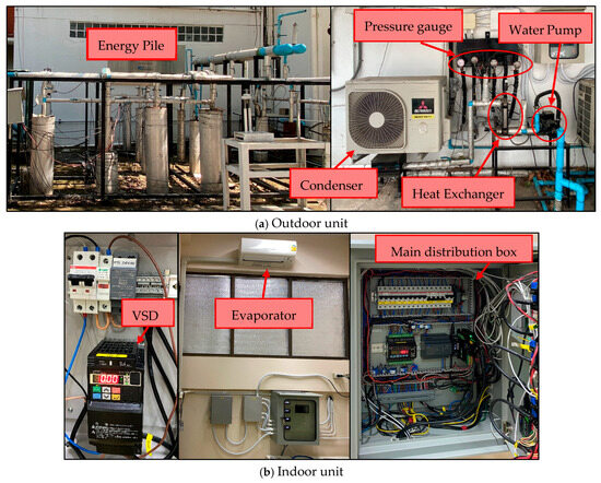
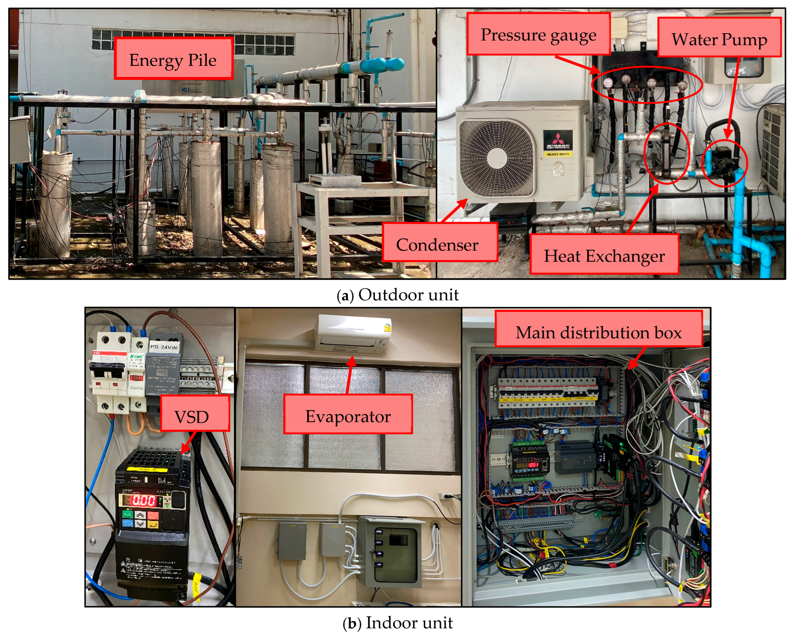
The Hybrid Geothermal Heat Pump (HGHP) system is a new concept for utilizing an air-source pump to improve conventional Geothermal Heat Pump (GHP) technology. Normally, the HGHP system uses an energy pile with an air-cooled condenser or cooling tower for heat dissipation. This study focuses on the HGHP as a full-scale installation at the Faculty of Engineering, Kasetsart University (Bangkhen Campus), Bangkok, Thailand, as illustrated in Figure 1. The outdoor unit (energy pile) provides a mechanism for exchanging heat between the circulating water and the underground soil, and the circulating water is then recirculated to exchange heat with the refrigerant in the air-conditioning cycle using a plate heat exchanger. A water pump controls the flow rate of the circulating water and receives control signals from a variable speed drive (VSD) located in the indoor unit.
Figure 1.
Hybrid Geothermal Heat Pump equipment: (a) is equipment from the outdoor unit; (b) is equipment from the indoor unit.
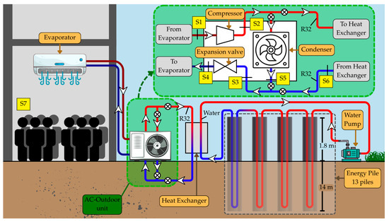
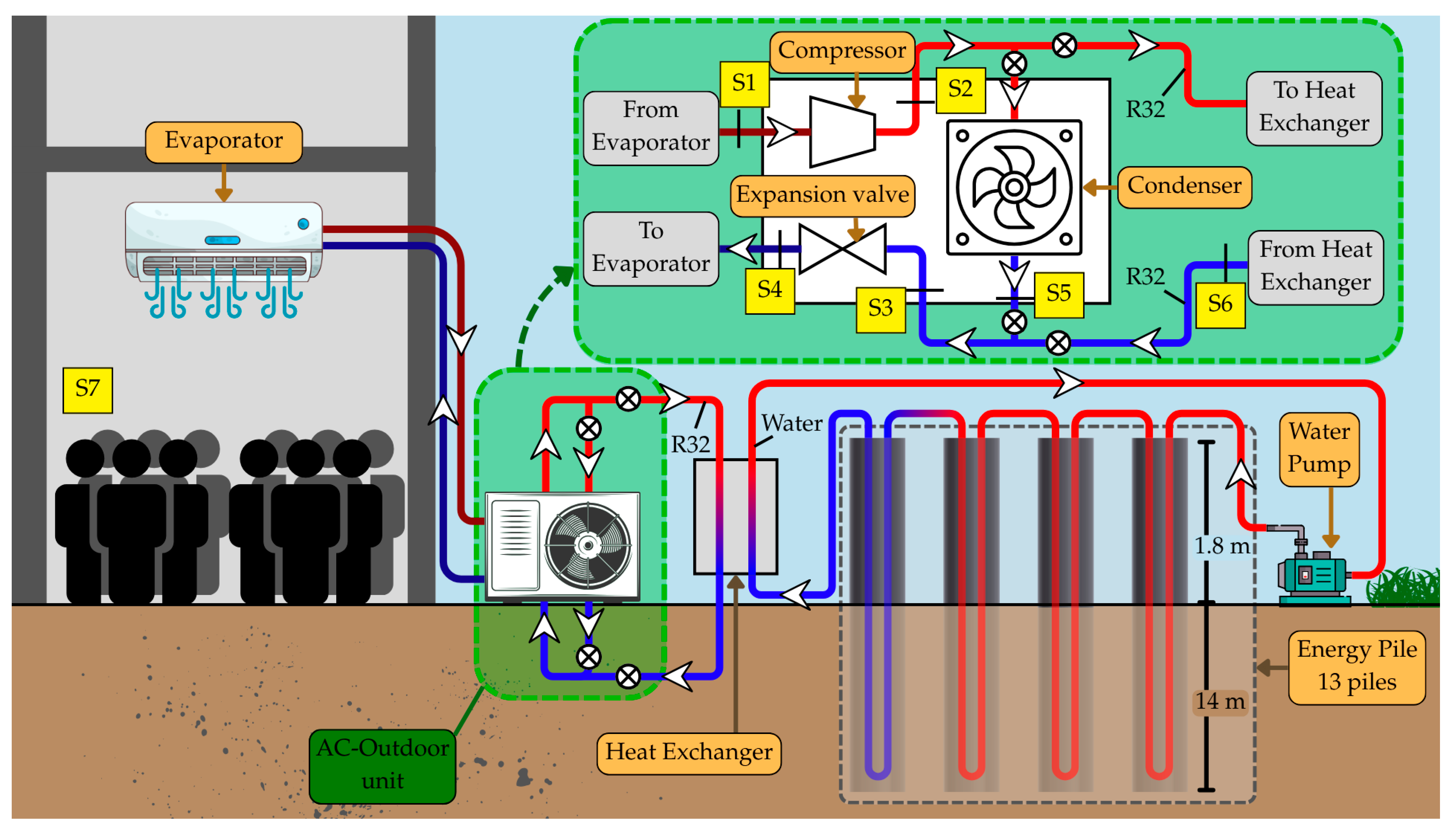
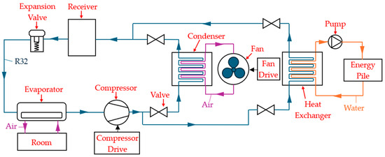
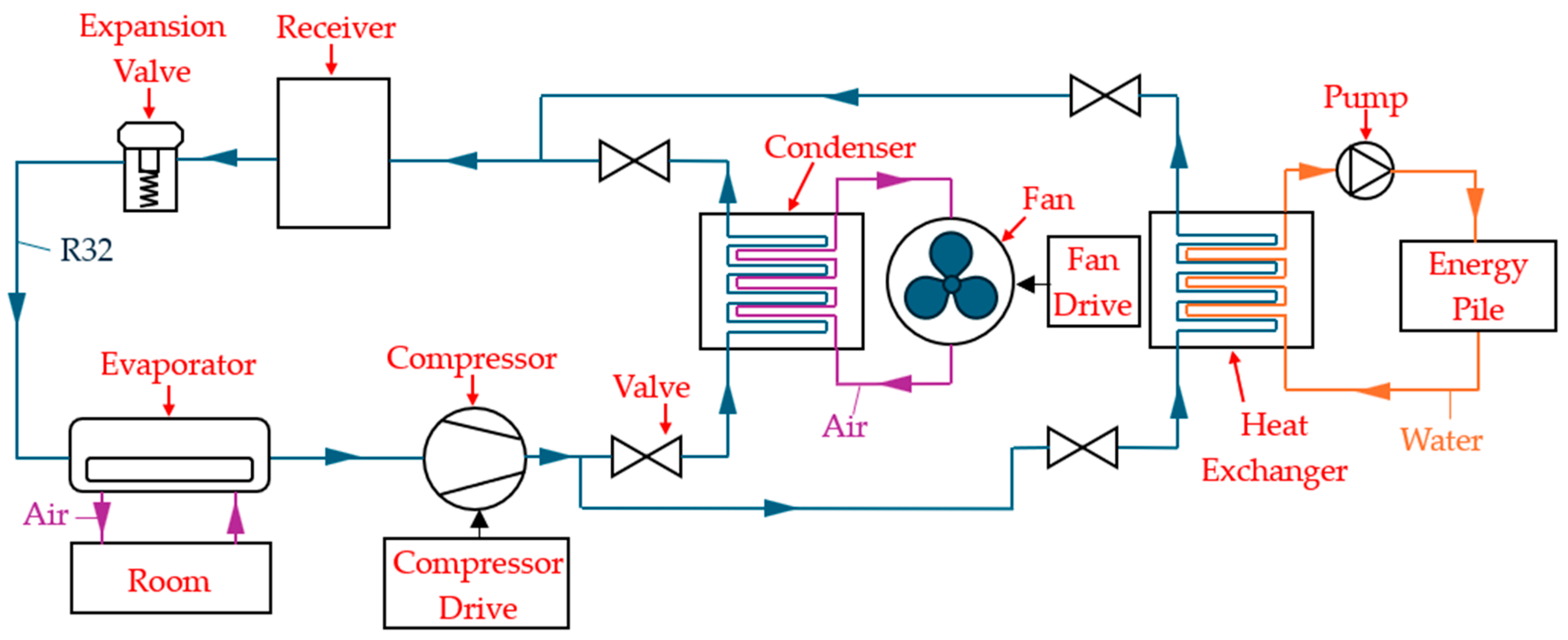
As illustrated in Figure 2, this study involves installing a network of sensors around the HGHP system to continuously log real-time data every 10 s. The sensor data were collected to quantify the operational efficiency of the system by measuring a wide variety of operational parameters, including the temperature and pressure of the R32 refrigerant in the system (monitored by sensors S1–S6 at multiple points), ambient air temperature, GHP circulating water temperature, total electrical power consumption of the system, and the temperature and relative humidity of the indoor environment (monitored by sensor S7).
Figure 2.
Hybrid Geothermal Heat Pump diagram.
One of the biggest advantages of this system is its flexibility in selecting the heat rejection method. Three operational modes are available based on the medium used for heat dissipation: using only energy piles (soil), utilizing only the air-cooled condenser (air), or a hybrid configuration employing both simultaneously. The selection of these modes is performed through the manual adjustment of directional valves that control the R32 refrigerant flow path (flow direction of R32 discharged from the compressor). The configuration of these valves and the resulting flow paths are detailed in the system schematic illustrated in Figure 2. Based on what specific valves are used to connect the R32 refrigerant, 3 modes of operation will be available for this system, detailed as follows:
- Air-Conditioning Mode (AC): Uses only the air-cooled condenser to reject heat to the air outside the building (no energy piles).
- Geothermal Heat Pump Mode (GHP): Uses only the geothermal energy piles as a medium means all thermal energy rejected from the system is rejected directly into the surrounding soil via the circulating water in the geothermal energy piles through the plate heat exchanger.
- Hybrid Geothermal Heat Pump (HGHP): Utilizes both mediums (air-cooled condenser and energy piles) simultaneously, yielding the maximum amount of thermal energy rejected and maximizing the operational efficiency of the entire system.
The HGHP system is separated into an AC unit and a GHP unit. The air-conditioning system that was tested has a cooling capacity of 11,634.31 BTU. This air-conditioning unit was installed in a room with a total volume of 48 m3. The air-conditioning unit has three adjustable fan numbers for cooling and operates in either cooling or dehumidification mode. The air-conditioning unit is also connected to a GHP system comprising 13 energy piles, with a total piping length of 355.92 m. For more information, refer to Table 2.
Table 2.
Properties of the Hybrid Geothermal Heat Pump System.
2.2. Base Controller
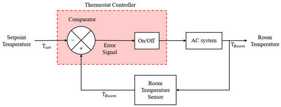
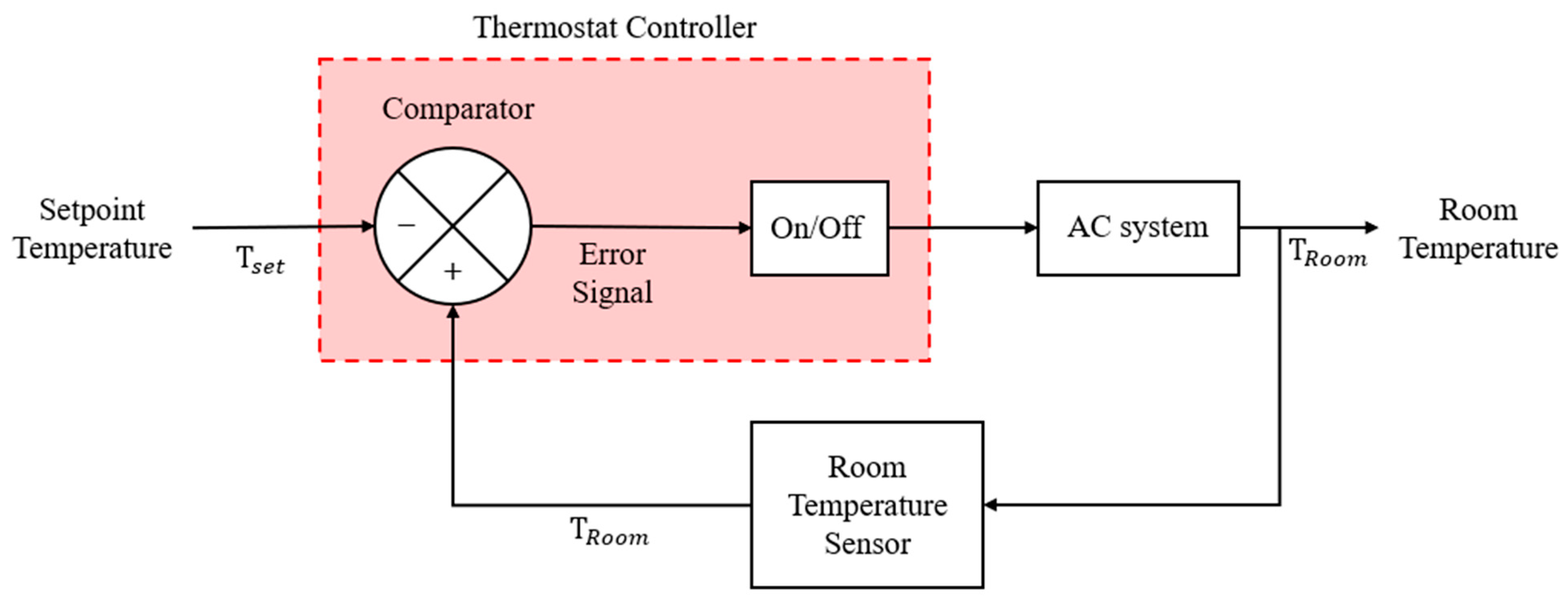
This research uses a standard controller commonly referred to as a “thermostat controller,” which is incorporated into all standard air-conditioning systems. The flow diagram of the controller seen in Figure 3 shows the basic on–off control logic. The controller continuously monitors the indoor temperature using the temperature sensors and compares the measured temperature value with the user-defined setpoint temperature (). A deadband is applied around the setpoint to provide operational stability and reduce the likelihood of frequent short-cycle compressor operation. If the temperature exceeds the upper or lower limit of the defined deadband, the controller sends binary signals to turn the air-conditioning system on or off. The main purpose of this on–off control is to control the operation of the air-conditioning system to maintain indoor temperatures near the target .
Figure 3.
Base Controller workflow diagram.
2.3. Simulation System Verification
The HGHP modeling process involved using the MATLAB Simulink® R2025b modeling environment and creating simulations that faithfully reproduced both the physical characteristics and the performance and efficiency of the actual hardware system. The various components of the system were built from preexisting components in the Simscape™ library, as shown in Figure 4. In using R32 as the refrigerant, there are components representative of the evaporator (to absorb the indoor heat), compressor (to raise the pressure of the refrigerant and assure flow), air-cooled condenser (to reject heat to the outdoors), expansion valve (provide a pressure drop before the refrigerant returns to the evaporator), receiver tank (refrigerant storage), and plate heat exchanger (to transfer heat to the water that will be flowing through the energy piles, which are underground geothermal loops). In addition, there is a directional valve control system incorporated into the model that will allow for the direction of refrigerant flow to the condenser, the heat exchanger, or both simultaneously to accommodate the proposed hybrid control approach. When the system operates in the baseline mode, the thermostat-based control of the compressor and condenser is achieved through the transmission of binary direction control signals (0 or 1) to activate or deactivate the compressors and condensers.
Figure 4.
Hybrid Geothermal Heat Pump simulation model.
The is calculated using Equation (1) to assess how accurate the simulated model is compared with the physical reality. The is calculated using a relative difference between the simulated values () and the actual operating values (). This provides a measure of whether or not the model is valid over time.
The coefficient of performance (COP) is calculated as the ratio of the cooling capacity to the total electrical energy consumed according to Equation (2) [6]. The refrigerant mass flow rate () multiplied by the difference in evaporator enthalpy (), divided by the total power input, gives us the cooling capacity of the refrigerant (). To ensure a comprehensive analysis, in this study is calculated by accounting for the power consumed by all primary components, where is the energy consumption of the evaporator, is the energy consumption of the compressor, is the energy consumption of the condenser fan, and is the energy consumption of the water pump. This explicit breakdown of the total energy consumption allows for a precise evaluation of the system’s operational efficiency and provides a clear foundation for the component-specific control logic discussed in later sections.
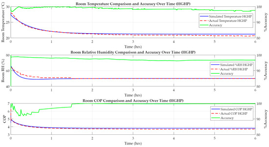
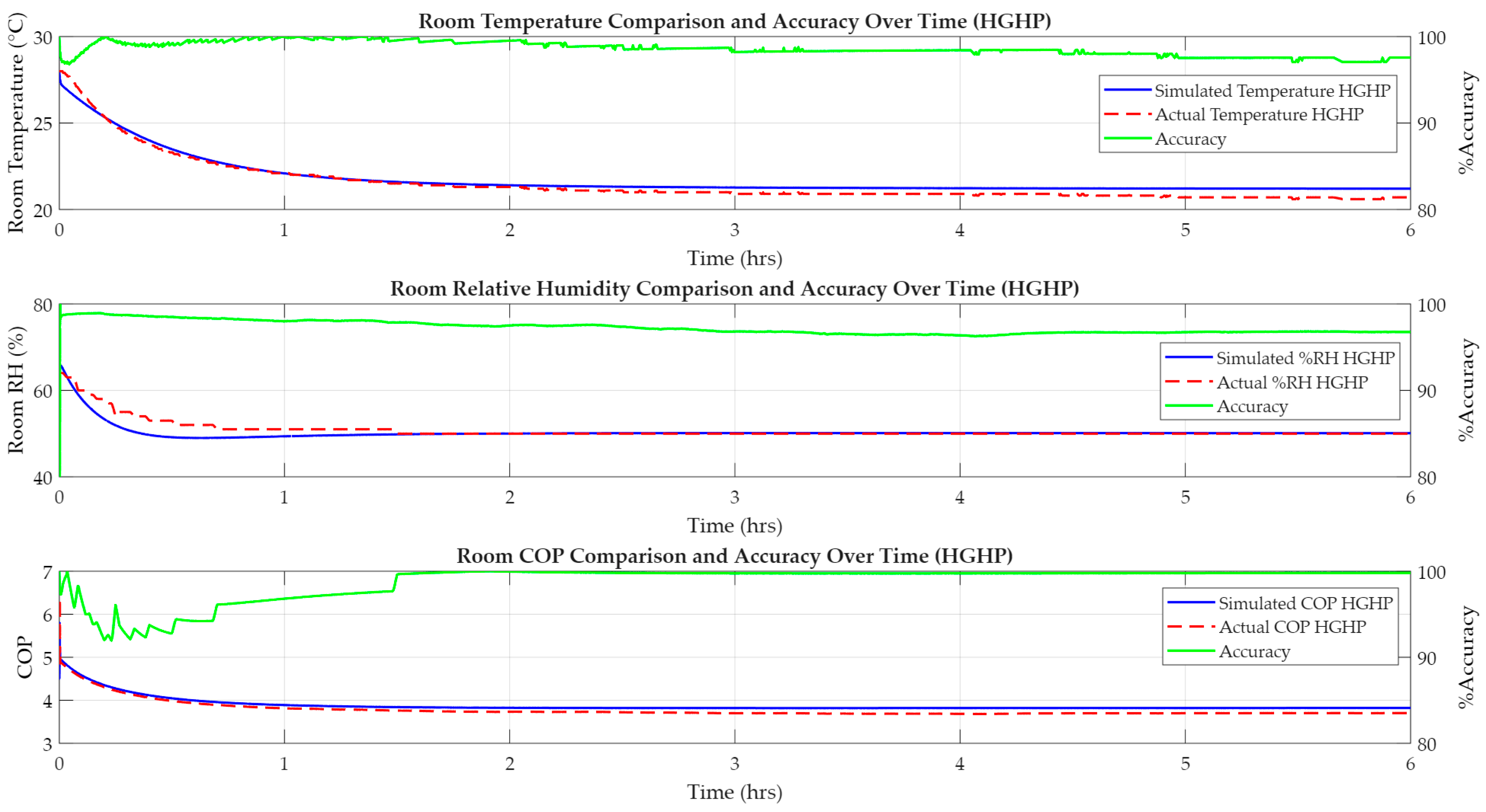
For the verification process, the system was configured with a setpoint temperature () of 18 °C and a VSD frequency of 40 Hz. This was to simulate the operational limits of the systems, rather than operating under normal conditions. From Figure 5, the results of the respective comparisons of indoor room temperature, relative humidity, and COP (blue line: data from the simulation system; red line: data from the actual system) demonstrate that the HGHP proposed model achieves a percentage accuracy (green line) in excess of 90%, thereby supporting the reliability of developing and testing these advanced control strategies in this research.
Figure 5.
HGHP Simulation System comparison.
2.4. Fuzzy Logic Controller Design
The Fuzzy Logic Control (FLC) system, based on fuzzy set (fuzzy logic) theory, processes its inputs using fuzzy set values, or “degrees of truth,” on the continuum from 0 to 1, allowing for more nuanced reasoning than can be achieved with binary Boolean logic. Figure 6 illustrates the Fuzzy Logic Control Architecture, which comprises four main components. Fuzzification converts crisp (numerical) inputs into linguistic (fuzzy) inputs, Fuzzy Inference (expert “If-Then”) Production Rules are applied for decision-making using an inference engine, and defuzzification converts fuzzy (linguistic) results back into crisp (numerical) outputs [19].
Figure 6.
Fuzzy Logic Control workflow diagram.
The Triangular Membership Function (TriMF) is used in this work for fuzzifying the input data because it has linearity properties and is computationally efficient [20]. As noted, the TriMF is characterized by three parameters (, , ). The triangular membership function is given by Equation (3):
The triangle created by input consists of its scalar parameters and , which define the interval of a triangle with membership equal to 0, with and as the lower and upper boundaries, respectively; the vertex of the triangle will be when has membership value of 1. Thus, for inputs in the range [, ] (inclusive), the function linearly increases from to b and then linearly decreases from b to . As such, the function will return a result of 0 for any input that lies outside the range [, ].
Following fuzzification, the transformed data is evaluated against the Fuzzy Rule Base to determine the appropriate fuzzy output. The Fuzzy Rule Base consists of a number of conditional statements that utilize fuzzy operators and fuzzy sets to define the logical antecedents and consequents upon which the rules are constructed. Each fuzzy rule base is created using the system’s linguistic variables to associate an input variable with an output variable through IF–THEN statements of fuzzy logic, in the form shown in Equation (4):
and in this equation refer to the two fuzzy sets ( or the fuzzy set of inputs and or the fuzzy set of outputs) that represent the linguistic terms of the fuzzy set defined in the input universe () and output universe (). The conditional statement has two main parts: an antecedent (premise) portion of “” followed by a consequent (conclusion) part of “”. A good set of rules requires a thorough understanding of the physical system so that the controller can respond correctly to dynamic conditions.
The last phase of turning a fuzzy output into a crisp output is referred to as defuzzification; it is the process of converting an aggregated fuzzy set into a crisp output signal for driving the control system. In this study, we used the centroid (or center of gravity) method for defuzzification because it computes the balancing point of the complete set of fuzzy outputs along the x-axis. This is very similar to finding the center of mass of a uniform-density plate. The crisp value is calculated as per Equation (5):
where represents the discrete element within the universe of discourse, and denotes the corresponding membership value for that point. This formula computes the weighted average of the fuzzy set, enabling smooth control and clear visualization.
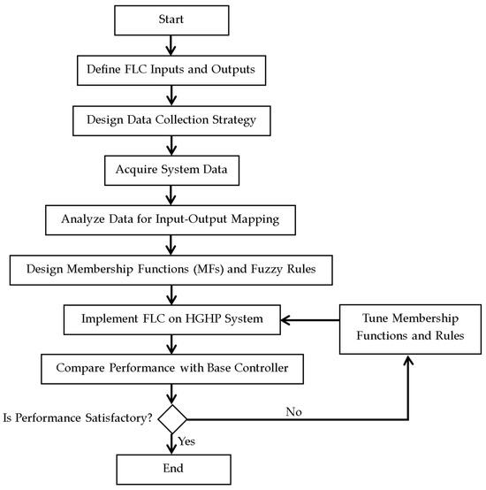
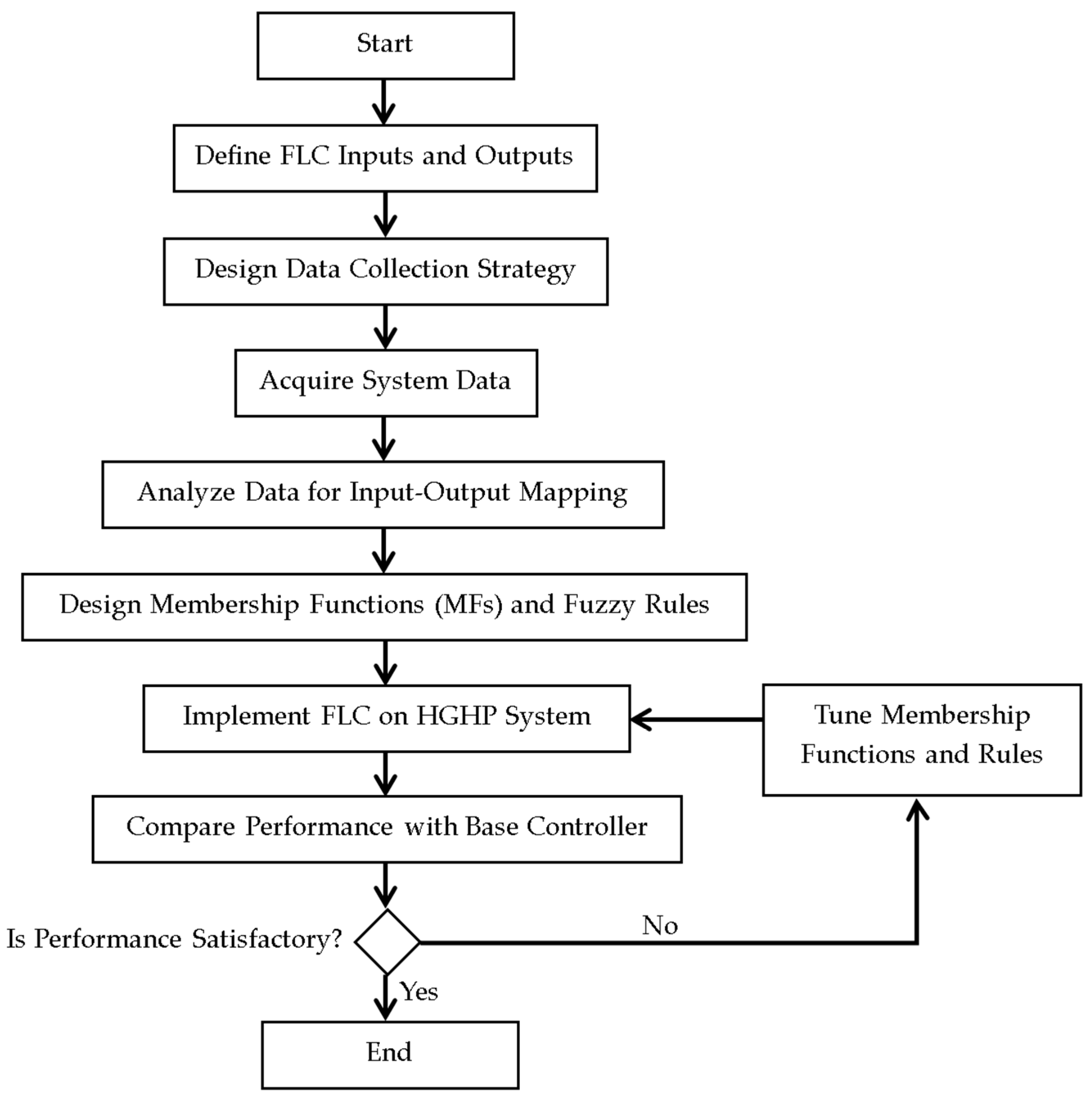
This research’s approach to developing the FLC adheres to the design flow diagram in Figure 7. First, the inputs and outputs of the system are identified to establish critical parameters for controlling the overall operation of the HGHP system. Second, operational data are collected from the HGHP system, which spans a range of operating conditions, to understand how the system behaves under these conditions. These empirical data become the foundation for designing the membership functions and fuzzy rules for that system. After the final design of the Fuzzy Logic Controller (FLC) is created and implemented on the HGHP system, the performance of the FLC can be evaluated. Then, the performance evaluation can be enhanced by either modifying the existing FLC or creating a new FLC to achieve optimal operation of the control method.
Figure 7.
FLC design flow diagram.
2.4.1. Define FLC Inputs and Outputs
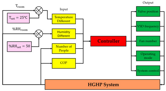
The control system presented in this research work dynamically monitors room occupancy to ensure thermal comfort in terms of both temperature and humidity, while also achieving the greatest possible energy efficiency. As illustrated by Figure 8, the architecture of the Fuzzy Logic Controller (FLC) integrates four different input variables and uses them to assess the optimal system state: the temperature difference (calculated by determining the difference between the measured temperature of the room and the desired setpoint of 25 °C); the humidity difference (calculated from the relative humidity measured in the room compared with the desired setpoint of 50% RH); the number of people in the room; and the current coefficient of performance (COP) of the system. These inputs were selected to balance occupant comfort with system efficiency. The temperature difference is the primary feedback for thermal stability, directly influencing compressor operation and fan number. The humidity difference allows the system to switch to the dehumidification mode to maintain air quality even when the temperature is stable. The number of people serves as a leading indicator of dynamic internal heat loads, enabling the controller to adjust the VSD frequency and valves pre-emptively. Lastly, the COP is monitored to ensure the controller selects the most energy-efficient operating mode (AC, GHP, or HGHP) based on real-time performance. The FLC uses its evaluation of these inputs to generate signals to five different actuators that control the Hybrid Geothermal Heat Pump System (HGHP). The valve position can be set to air-conditioning (AC), geothermal heat pump (GHP), or hybrid (HGHP) modes. The VSD frequency can modulate the water flow rate through the energy pile. The fan number modulates the evaporator fan speed to three levels. In addition, the controller controls system control functions by turning ON/OFF the compressor and condenser fan based on operational requirements, and the operating mode selected by the controller, either cooling (AC) or dehumidification (DH).
Figure 8.
FLC diagram workflow for Hybrid Geothermal Heat Pump.
2.4.2. Design Data Collection Strategy and Acquire System Data
To effectively evaluate the HGHP system performance, and as outlined by the controller’s architectural design, a complete assessment of the HGHP system’s ability to deliver cooling and dehumidification to the room, and the energy consumption of the system under different operating modes, needs to take place so that effective use of control logic can be applied. An analysis of the data collection techniques used for the system’s performance evaluation is provided in Table 3. The 13 experimental test cases were developed to evaluate the system’s performance under varying conditions. These conditions were evaluated by adjusting the valve configurations to determine each mode of primary operation: air conditioning (AC), geothermal heat pump (GHP), and hybrid (HGHP).
Table 3.
Data collection table.
The first 3 cases focus on the AC mode (valve AC). For these cases, the variable speed drive (VSD) is turned off, thereby allowing the energy pile to be bypassed for heat rejection. The evaporator fan number is increased from Level 1 to Level 3, with the evaporator still in AC mode at a setpoint temperature of 18 °C. The purpose of these tests is to evaluate the cooling capacity that the system will provide to the room at each level of fan number.
Cases 4 to 11 explore both GHP and HGHP modes. The VSD frequency is swept from 10 Hz to 40 Hz while maintaining a constant fan number of Level 3 during these experiments. The intent of this series of experiments is to identify the correlation between the water flow rates (controlled by the VSD) generated at each VSD frequency setting and the cooling effect of each geothermal and hybrid configuration.
Lastly, Cases 12 and 13 study how the evaporator mode affects cooling performance in comparison with dehumidification performance (AC versus DH). The tests are completed in conjunction with the HGHP configuration, with a VSD speed of 40 Hz and a setpoint temperature of 25 °C. The fan number operates at Level 1 in AC mode and Level 1 in DH mode, consistent with the equipment specifications. The purpose of these cases is to evaluate the system’s dehumidification capability compared with its cooling capability in various evaporator operating modes.
2.4.3. Analyze Data for Input–Output Mapping
According to the data collected in Section 2.4.2 of the HGHP system, there are clear differences in the performance capabilities for cooling capacity and energy use. Regarding cooling performance, the results indicate that the HGHP mode has the best cooling capacity, followed by the GHP mode and the AC mode. In addition, the VSD frequency and the AC fan number significantly impact the regulation of room temperature. Higher VSD frequencies correlate with lower room temperatures, which provide improved cooling performance. In addition, a Level 3 AC fan number lowers the best temperature compared with an AC fan number at Level 2 or 1.
The HGHP mode had the highest energy usage among the three operational modes, with the AC mode and GHP mode using less. One of the main findings relates to how VSD settings affect water pump energy consumption. Based on a regression analysis of the collected operational data, a non-linear cubic relationship was identified between the operating frequency ( and the pump power consumption (, as defined in Equation (6). Consequently, low-frequency operation minimizes energy consumption, whereas high-frequency operation significantly increases power demand. Because of this non-linear behavior, there is a major limitation on how the FLC must be designed, requiring that the FLC control logic be optimally selected for VSD frequencies so that adequate cooling demands are met without excessive power consumption due to high-frequency operation.
2.4.4. Design Membership Functions (MFs) and Fuzzy Rules
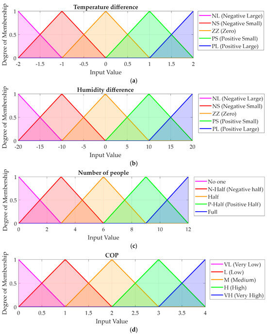
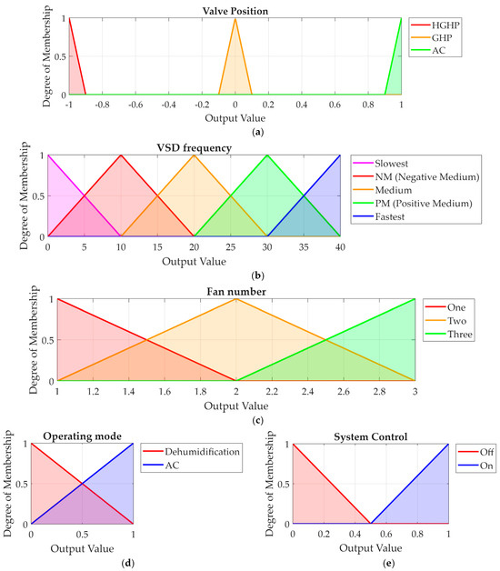
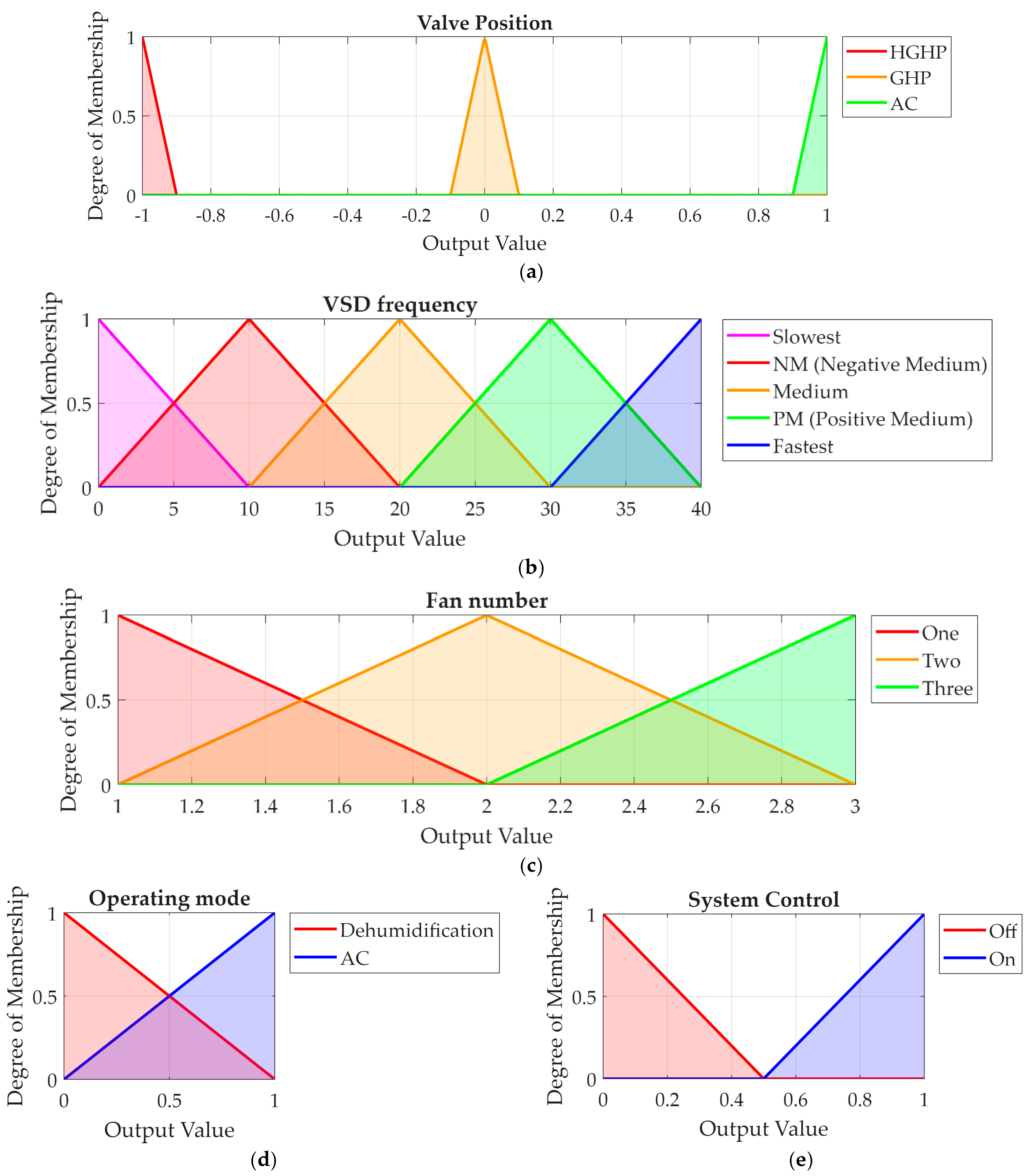
For the membership function (MF) development, the current research relies on the triangular membership function (TriMF) for the input and output variables; the input and output MF definitions appear in Table 4. As for the ranges of the input and output variables, the temperature difference and humidity difference values are defined symmetrically about zero to allow equal representation of both positive and negative deviations from the setpoint. Each input variable is defined using 5 separate linguistic terms, enabling precise error resolution based on what has been defined for each variable. Additionally, the occupancy variable and the COP variable are defined so that the controller can accommodate variable room loads and variable system efficiency states. Finally, with respect to the outputs, the VSD frequency variable is defined with 5 frequency levels, allowing very fine speed control of the motor. The valve position, fan number, and operating mode variables are defined as discrete actuators with associated operational states. Examples of the input MF and output MF are shown in the membership function graphs of Figure 9 and Figure 10, respectively.
Table 4.
Specification of input and output variables.
Figure 9.
FLC input membership function: (a) is a fuzzy set of temperature difference, (b) is a fuzzy set of humidity difference, (c) is a fuzzy set of number of people, and (d) is a fuzzy set of COP.
Figure 10.
FLC output membership function: (a) is a fuzzy set of valve position, (b) is a fuzzy set of VSD, (c) is a fuzzy set of fan number, (d) is a fuzzy set of operating mode, and (e) is a fuzzy set of system control.
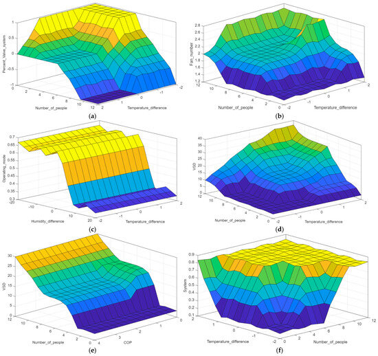
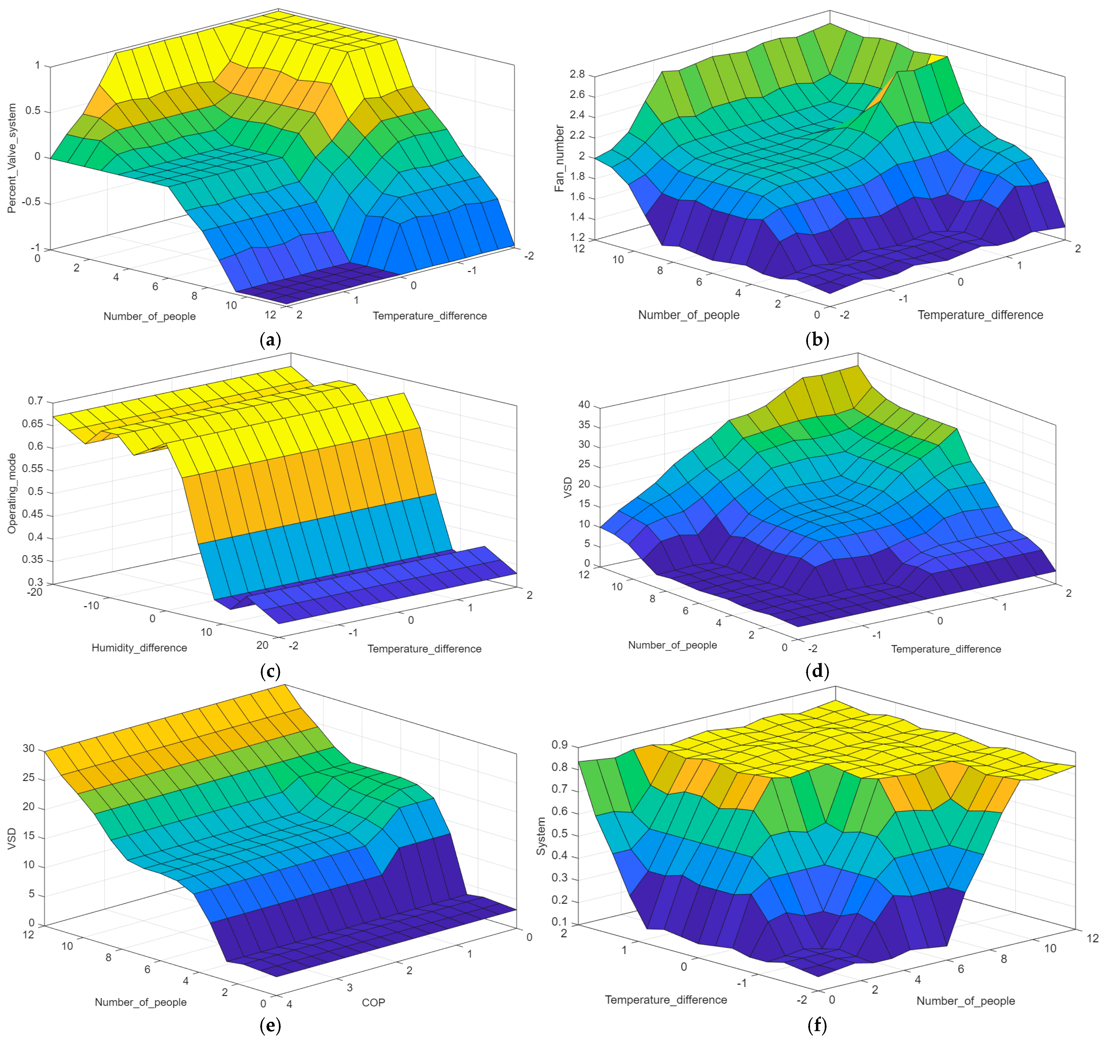
A complete set of IF–THEN rules was developed using the operational functions of the system to match the inputs to the outputs, which can be seen in Figure 11, showing the control surfaces of how it works. The primary control logic was developed to control the VSD frequency and valve position, with the cooling capability given priority during high-demand periods. When both the temperature difference and the number of people are high (for example, PL or Full), the system will switch to HGHP mode and use the fastest VSD frequency. At lower loads, the system will use the lower VSD frequency in GHP mode. There is also a separate rule to switch to AC mode at the slowest VSD frequency when the room is unoccupied (‘No one’) so that the on/off command can be issued from the system control panel. We also use VSD modulation to increase the COP by increasing the frequency when the COP is too low, thereby increasing the heat exchanged and improving efficiency.
Figure 11.
Control surface of fuzzy rule: (a) is the control surface of valve position with number of people and temperature difference; (b) is the control surface of fan number with number of people and temperature difference; (c) is the control surface of operating mode with humidity difference and temperature difference; (d) is the control surface of VSD with number of people and temperature difference; (e) is the control surface of VSD with number of people and COP; and (f) is the control surface of system control with number of people and temperature difference. The color gradient represents the magnitude of the output variable on the vertical axis, transitioning from dark blue (lowest values) to yellow (highest values).
The secondary optimization rules govern fan number, operating mode, and the system control. The fan number varies according to the temperature difference and the number of people to reduce the time it takes for the room to cool down. Operating Mode: When humidity levels indicate excessive moisture in the air, the system will operate in dehumidification mode; the system control logic will conserve energy by deactivating the system (‘Off’) when no one is present and maintaining a temperature slightly higher than the setpoint to allow for rapid recovery when someone returns.
3. Results
The Base Controller (BC) was compared to a proposed Fuzzy Logic Controller (FLC) in this study. The temperature setpoint for the BC was set to 25 to provide maximum thermal comfort to the occupants of the space. Both controllers were tested under identical environmental conditions for an equitable comparison. These included synchronized occupancy profiles for both controllers, the same initial indoor temperature and humidity for both controllers and the same hourly variation in outdoor ambient temperature for both controllers throughout the duration of each test.
3.1. Case Study
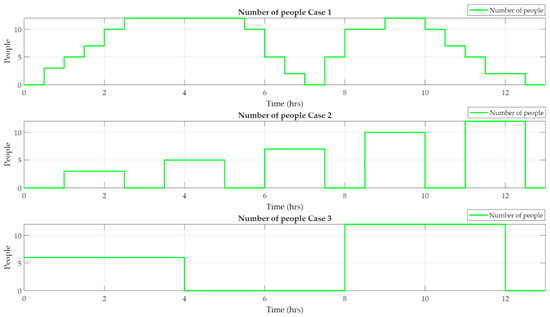
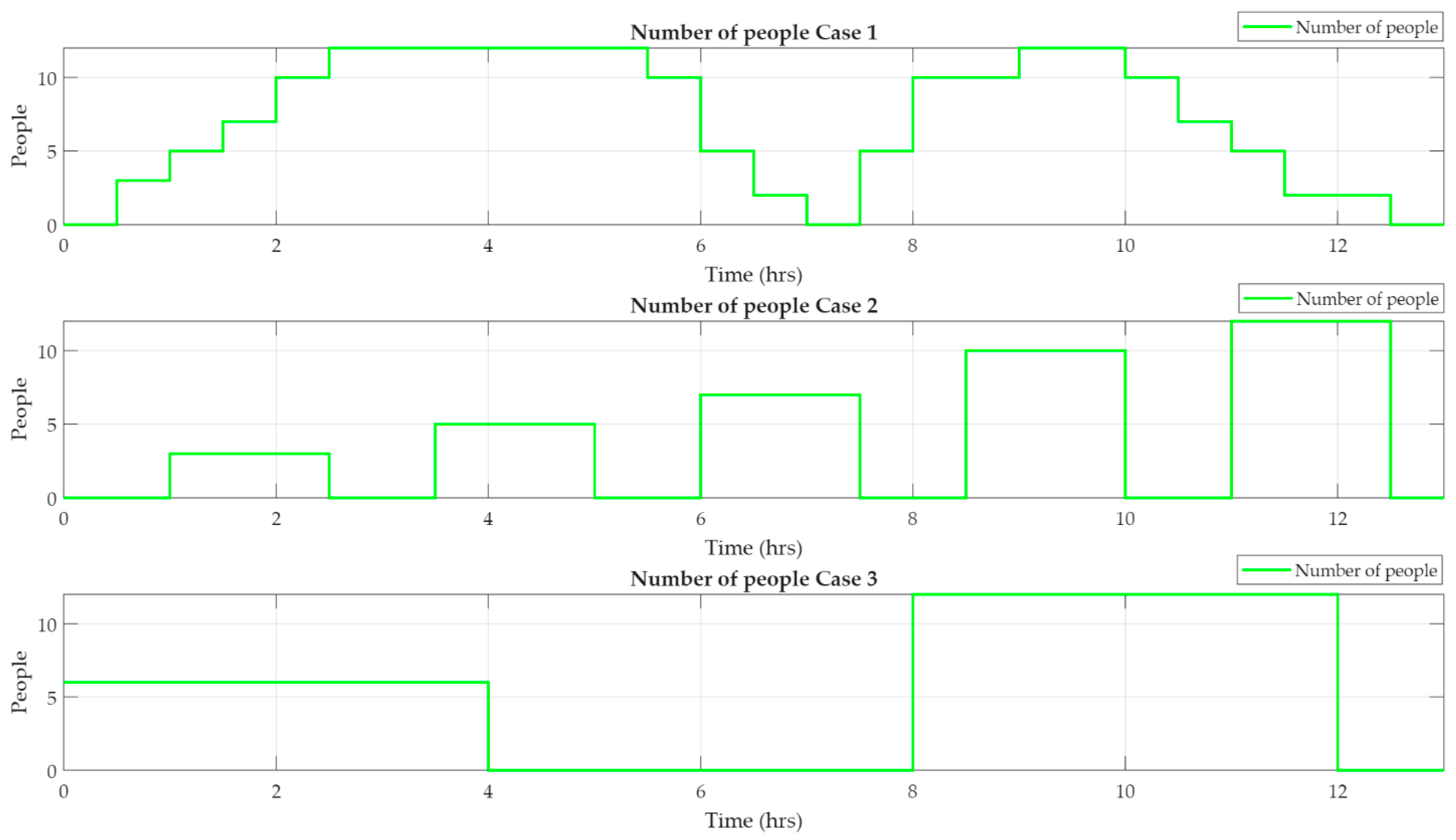
In this research, the authors categorize performance evaluation into three separate case studies (illustrated in Figure 12). Figure 12 shows an occupancy profile over time for up to 12 individuals occupying the space. By varying the number of individuals using the space, this study can demonstrate how control strategies can be applied in different situations. Case Study 1 tests the usage patterns of normal classroom users throughout the day. This includes using the space for morning classes, leaving it empty for lunchtime, and having it occupied after lunch. Case Study 2 looks at how the control system operates with normal occupancy; however, it does so with variable occupancy levels that are sudden and not gradual. Case Study 3 provides an opportunity to understand how the control system will perform with consistent occupancy levels over prolonged periods of time (steady-state mode).
Figure 12.
Number of people in each case study.
3.2. System Operation in Each Case
This report presents a comparative performance analysis between the proposed Fuzzy Logic Controller (FLC) and the conventional Base Controller (BC) within the Hybrid Geothermal Heat Pump (HGHP) system. The evaluation focuses on several key performance indicators: room temperature and humidity regulation, coefficient of performance (COP), and energy usage. In the subsequent graphical representations, the operational trajectories of the Base Controller are depicted in blue, while those of the FLC are distinguished in red.
3.2.1. System Operation in Case 1
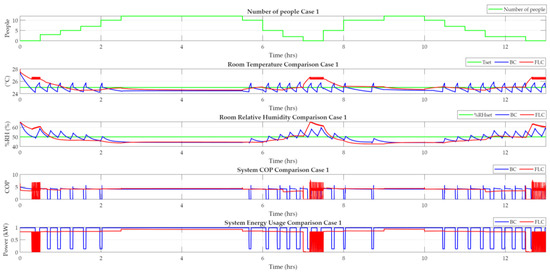
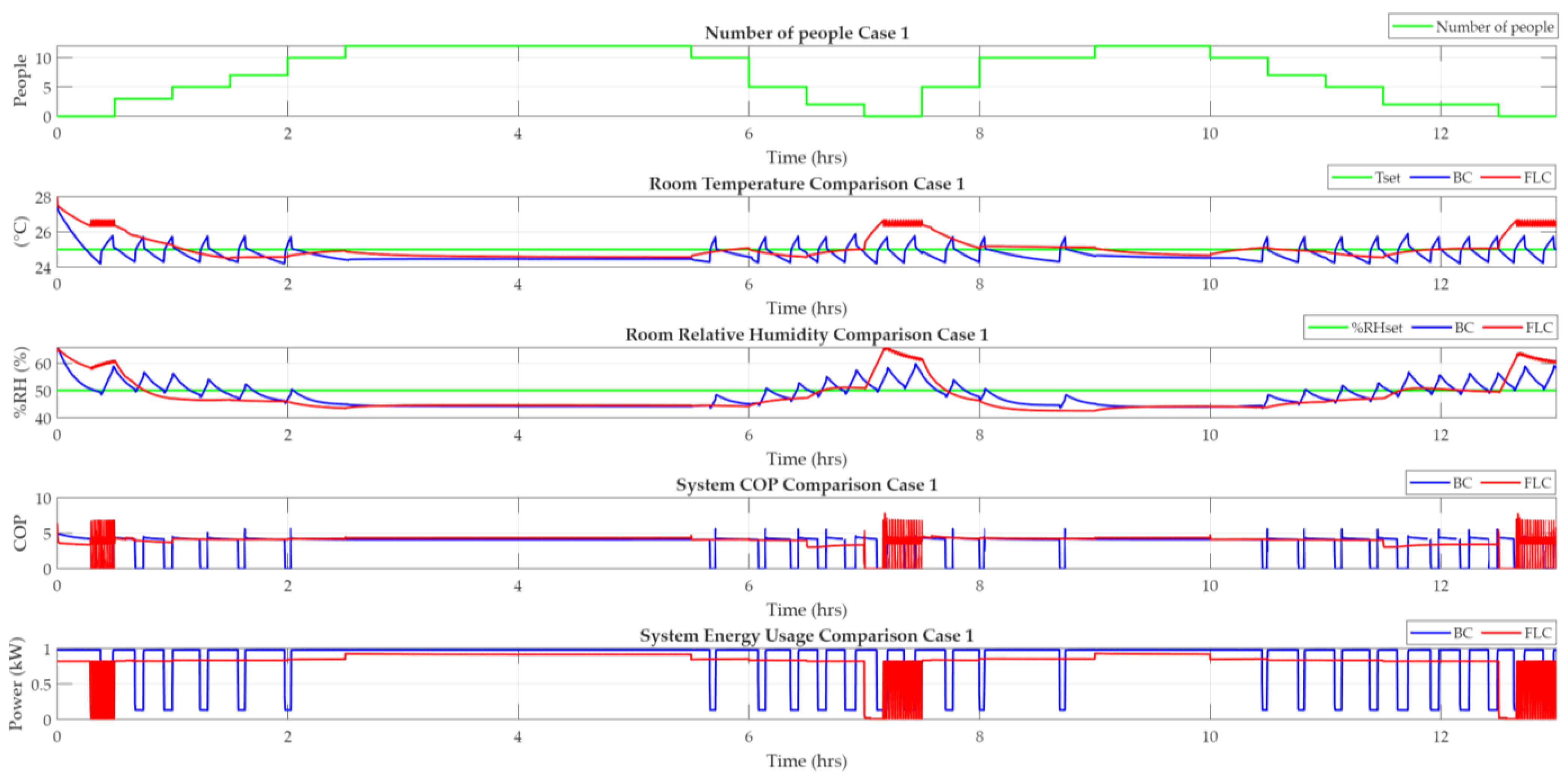
As shown in the graph in Figure 13, Case 1 demonstrates that the FLC outperforms each of the alternative control strategies in terms of stability for temperature regulation. The FLC returns the room temperature right to the setpoint with little fluctuation while maintaining superior stability compared with the Base Controller. The FLC dynamically adjusts the operation of the HGHP system based on real-time occupancy and has a greater coefficient of performance (COP) because of this dynamic adjustment. In terms of overall energy consumption, the FLC has lower energy consumption than the BC. A major factor contributing to energy savings is the FLC logic, which allows the room temperature to drift slightly above the setpoint during unoccupied periods to minimize overcooling of the space, while effectively recovering the room temperature immediately upon re-occupancy without creating high-energy demand. Additionally, as seen in the FLC results, the FLC monitors relative humidity (40–60% RH) and effectively limits it to the comfort zone when occupancy returns. The FLC also removes higher relative humidity accumulated during periods of vacancy when the occupant returns to their room.
Figure 13.
Comparison of the control system’s operation in Case 1.
3.2.2. System Operation in Case 2
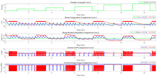
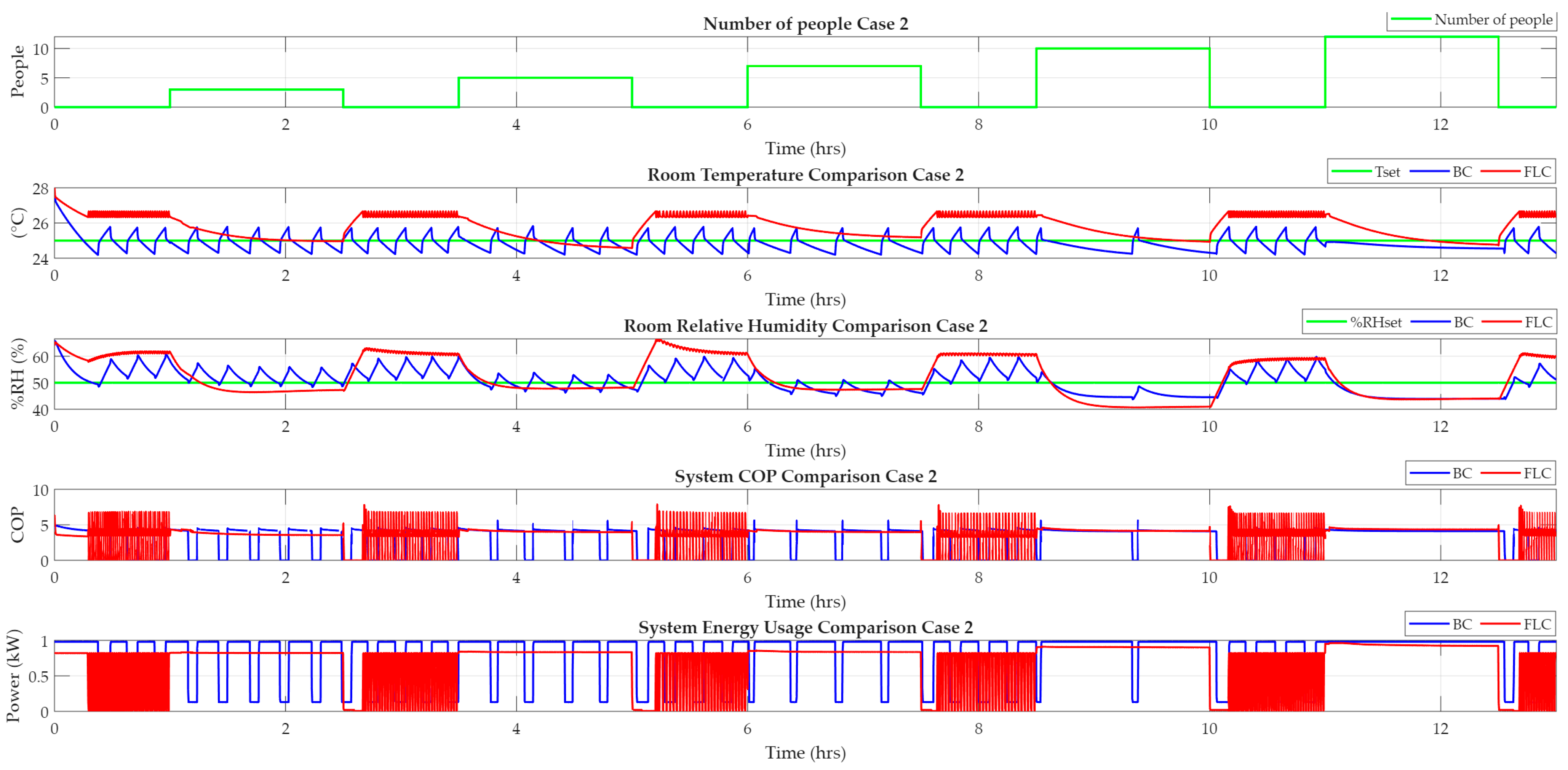
In Case 2, the operational comparison of the control systems is shown in Figure 14. The results show that while the FLC effectively changes how it regulates room temperature based on the number of people present, it does so by attempting to maintain the room temperature close to the set temperature when people are present. In contrast, the BC runs at its full capacity regardless of the amount of occupancy and, therefore, experiences significant peak energy consumption during startup. Additionally, the BC is also more unstable regarding temperature than the FLC because of the way in which the thermostat cycles on and off. Notably, at low levels of occupancy, the BC cycles on and off significantly more than it does at higher occupancy levels. As a result, the FLC has a considerable efficiency advantage over the BC with respect to its ability to operate in a more energy-efficient manner under partial-load conditions at low levels of occupancy.
Figure 14.
Comparison of the control system’s operation in Case 2.
3.2.3. System Operation in Case 3
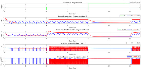
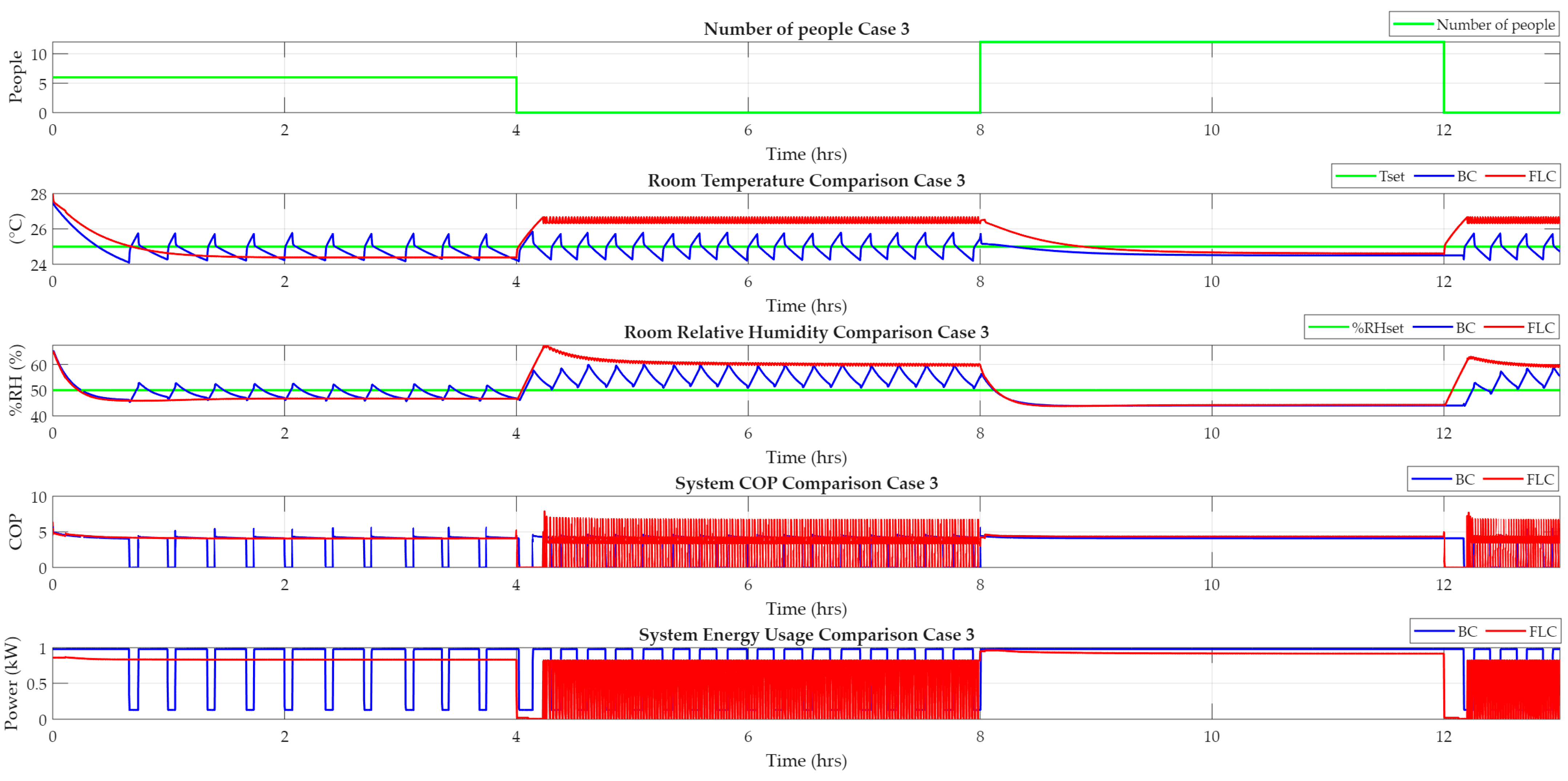
Figure 15 illustrates the comparative performance of the two control systems (FLC and BC) in Case 3. At half occupancy (six people), FLC maintains a stable room temperature, whereas BC exhibits oscillations due to on/off thermostat cycling. FLC’s COP also provides greater consistency than that of BC, and FLC consumes less energy at peak demand. At full occupancy (12 people), both systems maintain stable room temperatures with similar values; however, FLC consumes less energy than BC and has a slightly higher system COP. With regard to humidity control, both systems maintain room humidity in the comfort zone during use. FLC, due to the lack of a previous occupant load, allows the initial time humidity to exceed comfort limits; however, it stabilizes at approximately 60% RH and falls below comfort limits when occupants enter the space. Accordingly, FLC does not create excessive humidity levels during use.
Figure 15.
Comparison of the control system’s operation in Case 3.
3.2.4. Compare the Performance of the Controller
A quantitative comparison of the Base Controller and the Fuzzy Logic Controller across three case studies is presented in Table 5. In Case 1, representing normal room occupancy used in the second case study, the FLC provides the same degree of accuracy for both temperature and humidity control as the BC. The FLC also increases the cooling COP by 9.72% and reduces power consumption by 4.13%. In Case 2, the FLC achieves a 7.36% increase in COP and an 8.55% decrease in power consumption. Finally, in Case 3, the FLC achieves the maximum efficiency improvement of 11.76% in COP and a 7.55% reduction in power consumption. These findings show that the FLC improves energy efficiency for the HGHP system over the BC in each case study. Overall, these results demonstrate that both controllers maintain comfort levels; however, in terms of energy conservation and efficiency, the FLC is more efficient. The magnitude of energy savings will vary with occupancy patterns and the duration of unoccupied periods; therefore, the greatest energy savings are expected to be driven by these factors.
Table 5.
Comparison of the controller performance in each case.
4. Discussion
The experimental results demonstrate that while the BC can maintain the room temperature near the setpoint, it requires a significantly higher energy input compared with the FLC. This performance gap is primarily attributed to the FLC’s ability to handle the highly nonlinear thermal load characteristics of the HGHP system. By leveraging the flexibility of fuzzy linguistic variables, the proposed controller can process uncertain load fluctuations more effectively than the conventional on–off logic of the BC. Specifically, the fuzzy inference engine enables multi-objective synergy by dynamically modulating actuator responses (such as VSD frequency and fan number) based on real-time occupancy and measured COP, thereby optimizing the balance between occupant thermal comfort and the system’s energy demand. The FLC framework effectively manages conflicting objectives through dynamic operational transitions. While the HGHP mode is prioritized during high occupancy to maximize cooling capacity, the controller automatically shifts weights toward GHP or AC modes as the occupant density decreases. This transition is crucial for maintaining soil thermal balance and minimizing unnecessary power demand. During unoccupied periods, the FLC leverages system control signals to implement a demand-responsive strategy, allowing the room temperature to drift slightly above the setpoint. This approach is not only more energy-efficient than the BC’s rigid setpoint maintenance but also ensures a significantly faster thermal recovery to the desired setpoint upon re-occupancy compared with a complete system shutdown. Meanwhile, during occupied periods, FLC will continuously adjust the system to maintain a more stable, more consistent temperature than BC. Thus, FLC-driven HGHP systems will not only use less energy when compared with BC-driven HGHP systems but will also produce a higher average COP.
The main difference between the BC and the FLC is that the BC room will consistently have a relative humidity below 60% RH, whereas the FLC room will have a relative humidity of 60% RH or higher only when the device is turned off to conserve energy. However, once the 60% limit is reached, the FLC will turn on dehumidification to prevent the room from exceeding what users consider comfortable. While these two methods produce an average relative humidity accuracy that is lower in the FLC compared with the BC, the difference in averages does not have a significant impact on comfort due to the fact that the majority of humidity deviations will occur while the room is unoccupied (in other words, dehumidification in an unoccupied room is unnecessary as it has no impact on occupant comfort).
5. Conclusions
The objective of this research project was to analyze and compare the performance of a Base Controller (BC) and a Fuzzy Logic Controller (FLC) working together as part of a Hybrid Geothermal Heat Pump (HGHP) system. The evaluation test was conducted using a computer simulation based on an actual installation situated at Kasetsart University, Thailand. In this regard, the following provides a synopsis of the key findings from this study:
- The results indicate that, within the scope of this study, the FLC framework demonstrates a higher potential for optimization compared with the BC because of its ability to optimize continuously by controlling operational settings including operational mode, fan number, dehumidification mode, and VSD (variable speed drive) on a real-time basis based on occupancy while controlling the compressor and condenser on a separate system control to prevent unnecessary cooling of the system when unoccupied.
- Overall statistical accuracy for temperature and humidity measured at the FLC was close to the BC due to being designed for energy conservation during unoccupied periods; however, the environmentally controlled spaces operated at desirable stable comfort levels that exceeded BC for almost every occupied period measure taken throughout this study.
In summary, the FLC achieved COP improvements of up to 11.76% under the conditions studied. However, it is important to acknowledge that the current findings are derived from a simulation environment calibrated with data from a single installation and a specific room configuration. While these results demonstrate significant potential for energy efficiency and thermal comfort, the generalizability of the proposed framework should be further explored in larger-scale applications and different climate zones. This study provides a preliminary demonstration of how such a framework could contribute to energy conservation and carbon reduction targets, suggesting a pathway for enhancing sustainable smart building operations.
Author Contributions
Conceptualization, S.P.; Methodology, S.P.; Software, S.P.; Validation, T.K.; Formal analysis, K.K. and S.P.; Investigation, S.P. and T.K.; Resources, K.K. and K.C.; Data curation, S.P.; Writing—original draft, S.P.; Writing—review & editing, K.K.; Visualization, T.K.; Supervision, K.K., K.C. and T.K.; Project administration, K.K.; Funding acquisition, K.K. All authors have read and agreed to the published version of the manuscript.
Funding
This research was funded by the Graduate School Fellowship Program, the Faculty of Engineering, Kasetsart University (grant number: 68/04/ME/M.Eng).
Data Availability Statement
The original contributions presented in this study are included in the article. Further inquiries can be directed to the corresponding author.
Acknowledgments
The authors would like to thank the anonymous reviewers for their valuable comments and insightful suggestions, which significantly helped to improve the quality of this manuscript.
Conflicts of Interest
The authors declare no conflict of interest.
Abbreviations
The following abbreviations are used in this manuscript:
| HVAC | Heating, Ventilation, and Air Conditioning |
| GHP | Geothermal Heat Pump |
| COP | Coefficient of Performance |
| HGHP | Hybrid Geothermal Heat Pump |
| PID | Proportional–Integral–Derivative |
| FLC | Fuzzy Logic Control |
| VSD | Variable Speed Drive |
| AC | Air Conditioning |
| BTU | British Thermal Unit |
| SEER | Seasonal Energy Efficiency Ratio |
| Setpoint Temperature | |
| Simulated Values | |
| Actual Operating Values | |
| Refrigerant Mass Flow Rate | |
| Enthalpy of the Refrigerant Entering the Evaporator | |
| Enthalpy of the Refrigerant Leaving the Evaporator | |
| Total Power | |
| TriMF | Triangular Membership Function |
| DH | Dehumidification |
| MF | Membership Function |
| BC | Base Controller |
References
- ASHRAE. 2021 ASHRAE Handbook: Fundamentals, inch-pound, ed.; American Society of Heating Refrigerating and Air-Conditioning Engineers Inc. (ASHRAE): Peachtree Corners, GA, USA, 2021. [Google Scholar]
- Yuan, Y.; Gao, L.; Zeng, K.; Chen, Y. Space-Level air conditioner electricity consumption and occupant behavior analysis on a university campus. Energy Build. 2023, 300, 113646. [Google Scholar] [CrossRef] [Scilit]
- Er-retby, H.; Es-Sakali, N.; Mghazli, M.O.; El Mankibi, M.; Benzaazoua, M. Occupant behavior impact on energy efficiency and comfort in naturally ventilated buildings across climates using adaptive comfort: Models to metrics. Appl. Therm. Eng. 2026, 284, 129032. [Google Scholar] [CrossRef] [Scilit]
- Christodoulides, P.; Aresti, L.; Florides, G. Air-conditioning of a typical house in moderate climates with Ground Source Heat Pumps and cost comparison with Air Source Heat Pumps. Appl. Therm. Eng. 2019, 158, 113772. [Google Scholar] [CrossRef] [Scilit]
- Mohammadzadeh Bina, S.; Fujii, H.; Tsuya, S.; Kosukegawa, H. Comparative study of hybrid ground source heat pump in cooling and heating dominant climates. Energy Convers. Manag. 2022, 252, 115122. [Google Scholar] [CrossRef] [Scilit]
- Zhou, S.; Zhao, J. Comparative Analysis of Energy Efficiency in Air-conditioning System with GSHP, Electricity-driven Refrigerating Unit and Direct-fired Li-Br Absorption Refrigerating and Heating Unit. Energy Procedia 2012, 16, 673–678. [Google Scholar] [CrossRef] [Scilit]
- Sah, S.K.; Murugesan, K.; Rajasekar, E. Experimental comparison of First-law analysis of peak hour operation of GSHP system under optimized conditions. Appl. Therm. Eng. 2025, 258, 124525. [Google Scholar] [CrossRef] [Scilit]
- Man, Y.; Yang, H.; Wang, J. Study on hybrid ground-coupled heat pump system for air-conditioning in hot-weather areas like Hong Kong. Appl. Energy 2010, 87, 2826–2833. [Google Scholar] [CrossRef] [Scilit]
- Xie, Y.; Hu, P.; Li, S. Development of a doubly-fed compound control for hybrid ground source heat pump systems in hot summer and cold winter areas. Renew. Energy 2024, 237, 121568. [Google Scholar] [CrossRef] [Scilit]
- Siren, S.; Hirvonen, J.; Sormunen, P. Comparison of traditional and ambient air-assisted ground source heat pump systems using different bore field configurations. Energy Convers. Manag. 2025, 323, 119240. [Google Scholar] [CrossRef] [Scilit]
- Abir Ahsan, T.M.; Ahamed, M.S.; Hassan, A.A. Hybrid ground source heat pump for sustainable greenhouse climate control in hot and humid region. Sustain. Energy Technol. Assess. 2025, 83, 104615. [Google Scholar] [CrossRef] [Scilit]
- Xue, T.; Jokisalo, J.; Kosonen, R. Demand Response Potential of an Educational Building Heated by a Hybrid Ground Source Heat Pump System. Energies 2024, 17, 5428. [Google Scholar] [CrossRef] [Scilit]
- Grigorie, T.L. Fuzzy Controllers: Theory and Applications; IntechOpen: London, UK, 2011. [Google Scholar]
- Belman-Flores, J.M.; Rodríguez-Valderrama, D.A.; Ledesma, S.; García-Pabón, J.J.; Hernández, D.; Pardo-Cely, D.M. A Review on Applications of Fuzzy Logic Control for Refrigeration Systems. Appl. Sci. 2022, 12, 1302. [Google Scholar] [CrossRef] [Scilit]
- Ezber, S.; Akdogan, E.; Gemici, Z. Fuzzy Logic Control of Heating and Cooling in Buildings Using Intermittent Energy. In Advances in Intelligent Manufacturing and Service System Informatics; Springer: Singapore, 2023. [Google Scholar]
- Kaya, M.N.; Büyükzeren, R.; Pektaş, A. Performance Prediction of Air Source Heat Pumps Under Cold and Hot Ambient Temperatures Using ANFIS and ANN Models. Symmetry 2025, 17, 1728. [Google Scholar] [CrossRef] [Scilit]
- Shin, J.-H.; Kim, H.-J.; Lee, H.-G.; Cho, Y.-H. Variable Water Flow Control of Hybrid Geothermal Heat Pump System. Energies 2023, 16, 6113. [Google Scholar] [CrossRef] [Scilit]
- Kathiravel, R.; Zhu, S.; Feng, H. LCA of net-zero energy residential buildings with different HVAC systems across Canadian climates: A BIM-based fuzzy approach. Energy Build. 2024, 306, 113905. [Google Scholar] [CrossRef] [Scilit]
- Sabri, N.; Aljunid, S.; Salim, M.; Badlishah, R.; Kamaruddin, R.; Malek, M. Fuzzy inference system: Short review and design. Int. Rev. Autom. Control. 2013, 6, 441–449. [Google Scholar]
- Chuensiri, S.; Katchasuwanmanee, K.; Wisessint, A.; Jotisankasa, A.; Soralump, C.; Siriyakorn, V.; Kerdphol, T.; Sanposh, P. Implementation of Adaptive Network-Based Fuzzy Inference for Hybrid Ground Source Heat Pump. IEEE Access 2024, 12, 21052–21069. [Google Scholar] [CrossRef] [Scilit]



Disclaimer/Publisher’s Note: The statements, opinions and data contained in all publications are solely those of the individual author(s) and contributor(s) and not of MDPI and/or the editor(s). MDPI and/or the editor(s) disclaim responsibility for any injury to people or property resulting from any ideas, methods, instructions or products referred to in the content. |
© 2026 by the authors. Licensee MDPI, Basel, Switzerland. This article is an open access article distributed under the terms and conditions of the Creative Commons Attribution (CC BY) license.