


Abstract
The large-scale grid integration of photovoltaic systems, accompanied by extensive power electronic equipment, exacerbates the risk of sub-synchronous oscillation (SSO) and poses a serious threat to the safe and stable operation of modern power systems. To address the limitation that traditional additional damping controllers rely on accurate mathematical models of the system, this paper applies model-free adaptive control (MFAC) to suppress sub-synchronous oscillation in photovoltaic systems. The proposed method requires no prior identification of the plant model and achieves adaptive control by online estimation of pseudo-partial derivatives using only system input-output data, with parameters optimized by particle swarm optimization. Simulation results show that the proposed controller can effectively shorten the settling time and suppress oscillations However, for oscillations induced by different mechanisms, it still has the limitation of requiring parameter re-optimization. This approach provides a new model-free technical pathway for sub-synchronous oscillation mitigation in grid-connected photovoltaic systems.
1. Introduction
With the full implementation of the ‘dual carbon’ goals and the accelerated development of a new type of power system, new energy generation centered on wind power and photovoltaics has become a key support for the transformation of China’s energy structure, and in the future will gradually take a dominant position in power supply [1,2]. SSO is a typical dynamic stability problem in power systems. It is formally defined by the IEEE Sub-synchronous Resonance Working Group as an electric power system condition where the electric network exchanges significant energy with system components at one or more natural frequencies of the combined system below the synchronous fundamental frequency of the power grid (50 Hz or 60 Hz) following a disturbance from equilibrium [3]. Under this development trend, a large number of power electronic devices are operating in parallel with the grid, profoundly changing the dynamic characteristics of the traditional power grid, causing sub-synchronous oscillation problems to exhibit significant new mechanisms and new features. This type of new wide-band oscillation problem, induced by the coupling of high-penetration new energy and power electronics, is highly likely to trigger system instability, seriously threatening the safe and stable operation of the power grid, and has also become a key technical bottleneck restricting the large-scale and efficient consumption of new energy [4].
In recent years, there have been multiple incidents of SSO caused by the integration of new energy sources into the grid in China. Between 2011 and 2013, the series-compensated doubly-fed wind farms in Guyuan, Hebei, and since 2015, the wind power base in Hami, Xinjiang, have all experienced sub-synchronous oscillations, seriously threatening the safe and stable operation of the power grid [5,6]. Currently, related accidents are concentrated in wind power systems, and sub-synchronous oscillations caused by photovoltaic (PV) grid integration have not yet been reported. However, both PV and wind power use inverter-based grid connection, and thus also face the risk of oscillations. Therefore, studying the oscillation mechanisms and suppression strategies of PV grid-connected systems has become an important topic for ensuring the safe and stable operation of the power grid [7].
At present, three typical technical routes have been formed for the suppression of sub-synchronous oscillations: first, to change the inherent dynamic characteristics of the system by optimizing the electrical parameters of the power grid and equipment [8]; second, an additional damping control loop is added to provide oscillation damping and dissipate disturbance energy [9]; The third is to use series or parallel flexible AC transmission system (FACTS) devices to achieve active suppression [10]. Among many schemes, subs-synchronous damping controllers (SSDC) have become a key oscillation suppression method in engineering and academia due to their simple structure, high cost performance, and outstanding damping effect, and have been widely studied and applied. Existing research has explored the access mode and control structure of SSDC.
There have been numerous studies on SSO control strategies for wind turbine systems. Reference [11] compares the suppression effects of a Sub-synchronous Damping Controller when integrated into the rotor-side converter versus the grid-side converter, concluding that the former is more suitable as the additional location for the SSDC. Ref. [12] proposes a fractional-order sliding mode control strategy to address the SSO issue caused by the integration of a doubly-fed induction generator-based wind farm into a voltage source converter-based multi-terminal direct current system. Ref. [13] proposes a sub-synchronous oscillation stability analysis method based on the concept of security region. By constructing an operating condition-dependent impedance model and employing the predictor-corrector technique to fit the boundary, this method achieves efficient identification and assessment of oscillation stability in wind power systems under various operating conditions. Ref. [14] utilized particle swarm optimization algorithm to offline optimize SSDC parameters, enabling them to adapt to sub synchronous oscillation suppression under different degrees of series compensation, but did not consider the impact of dynamic changes in control parameters.
Research on SSO control strategies in grid-connected photovoltaic systems is still in the stage of gradual improvement. Ref. [15] proposes an optimization method for current loop gain parameters and photovoltaic inverter control parameters using the whale migrating algorithm (WMA), which balances algorithm exploration and exploitation capabilities to avoid local optima and achieve effective convergence. Ref. [16] points out that there is also an interactive control effect between the static var generator and the photovoltaic power generation system, necessitating reasonable design of their control parameters to enhance overall system stability. Ref. [17] proposes a resonance suppression method for photovoltaic power plants based on static var generator (SVG) high-frequency impedance reshaping. By implementing high-frequency phase compensation of the SVG, effective suppression of high-frequency oscillations in photovoltaic power plants is achieved, along with a corresponding parameter tuning method. Ref. [18] addresses the scenario of photovoltaic integration into DC grids by proposing an active damping stability control method. A virtual resistor is inserted into the DC grid-side port of the grid-connected photovoltaic power generation unit, ensuring good stability of the generation unit under different output power levels. Ref. [19] takes the desert and Gobi photovoltaic grid-connected system as the research object. Based on the traditional dual-loop current control strategy, a system impedance model considering the phase-locked loop is established. Subsequently, the inverter impedance is decomposed, and corresponding adaptive control loops are designed for each impedance component to improve system impedance according to the real-time operating status of the photovoltaic grid-connected system. Ref. [20] proposes a power oscillation suppression strategy for photovoltaic power generation systems based on an adaptive quasi-resonant controller. Ref. [21] establishes a relevant mathematical model for the impact of grid sub-synchronous oscillation on grid-connected photovoltaic inverters and proposes an adaptive quasi-resonant controller optimized by an improved Prony algorithm to eliminate oscillation disturbances. Finally, the effectiveness of this suppression strategy is verified through simulation. Ref. [22] proposes an online detection method for electromechanical oscillations based on a non-stationary second-order autoregressive model and Bayesian estimation, which provides transmission operators with stability margin information by calculating the posterior probability of pole instability.
The aforementioned control strategies for wind turbines and photovoltaic systems all belong to model-based control (MBC), whose effectiveness strictly relies on the prior foundation of a high-precision mathematical model of the system. However, unmodeled dynamics and multi-source uncertainties are inevitable during the modeling process, which may lead to poor adaptability of the closed-loop control system. Notably, the unknown and uncertain nature of controller parameters in practical control systems directly undermines the core assumption of model-based control—namely, that the system dynamics can be accurately described by a precise mathematical model—thereby making it difficult to effectively apply model-based control methods.
Traditional control methods rely heavily on accurate mathematical models of systems. Their damping performance is limited in the face of complex uncertainties and operating condition variations, making it difficult to meet the stability control requirements of new-type power systems. In recent years, data-driven control (DDC) has become an important approach for addressing oscillation issues in complex systems due to its independence from prior models.
MFAC designs the controller using only system input and output data, with its core idea being the dynamic linearization of nonlinear systems. The compact-form dynamic linearization (CFDL) features a simple structure, few parameters, and good real-time performance, making it the most widely used type of MFAC. Recently, researchers have introduced MFAC into the suppression of sub-synchronous oscillations in wind power systems. Ref. [23] combined CFDL-based MFAC with a static SSDC, and the designed damping controller effectively suppressed sub-synchronous oscillations under various operating conditions. Ref. [24] integrated CFDL-type MFAC with a conventional SSDC, showing strong adaptability in both single-machine and multi-machine systems. Ref. [25] compared the control performance of partial form dynamic linearization (PFDL), full form dynamic linearization (FFDL), and CFDL-type MFAC, indicating that the former two provide superior damping performance and robustness under variable wind speed and variable series compensation ratio conditions.
In existing studies on sub-synchronous oscillation suppression, most control strategies rely heavily on accurate mathematical models of wind turbines or photovoltaic systems. Furthermore, current research on MFAC only targets SSO caused by series-compensated wind farms. Accordingly, this paper innovatively applies MFAC to photovoltaic grid-connected systems. Compared with conventional control schemes for PV systems, the proposed strategy frees itself from dependence on precise mathematical models, utilizing system input and output data, without prior identification of the controlled plant’s structure.
This paper adopts MFAC theory to design a damping controller, aiming to suppress SSO in photovoltaic grid-connected systems. The specific research contents are as follows: First, a novel supplementary damping controller is designed based on the MFAC theory. Second, an optimization scheme for the controller parameters is established using the particle swarm optimization algorithm. Finally, time-domain simulations are conducted to verify the suppression performance of the proposed controller on SSO under various scenarios.
2. MFAC-SSDC Structure and System Dynamic Linearization
2.1. MFAC-SSDC Controller Structure
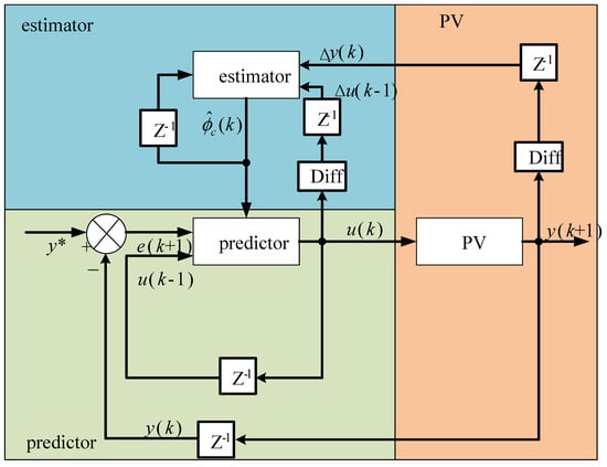
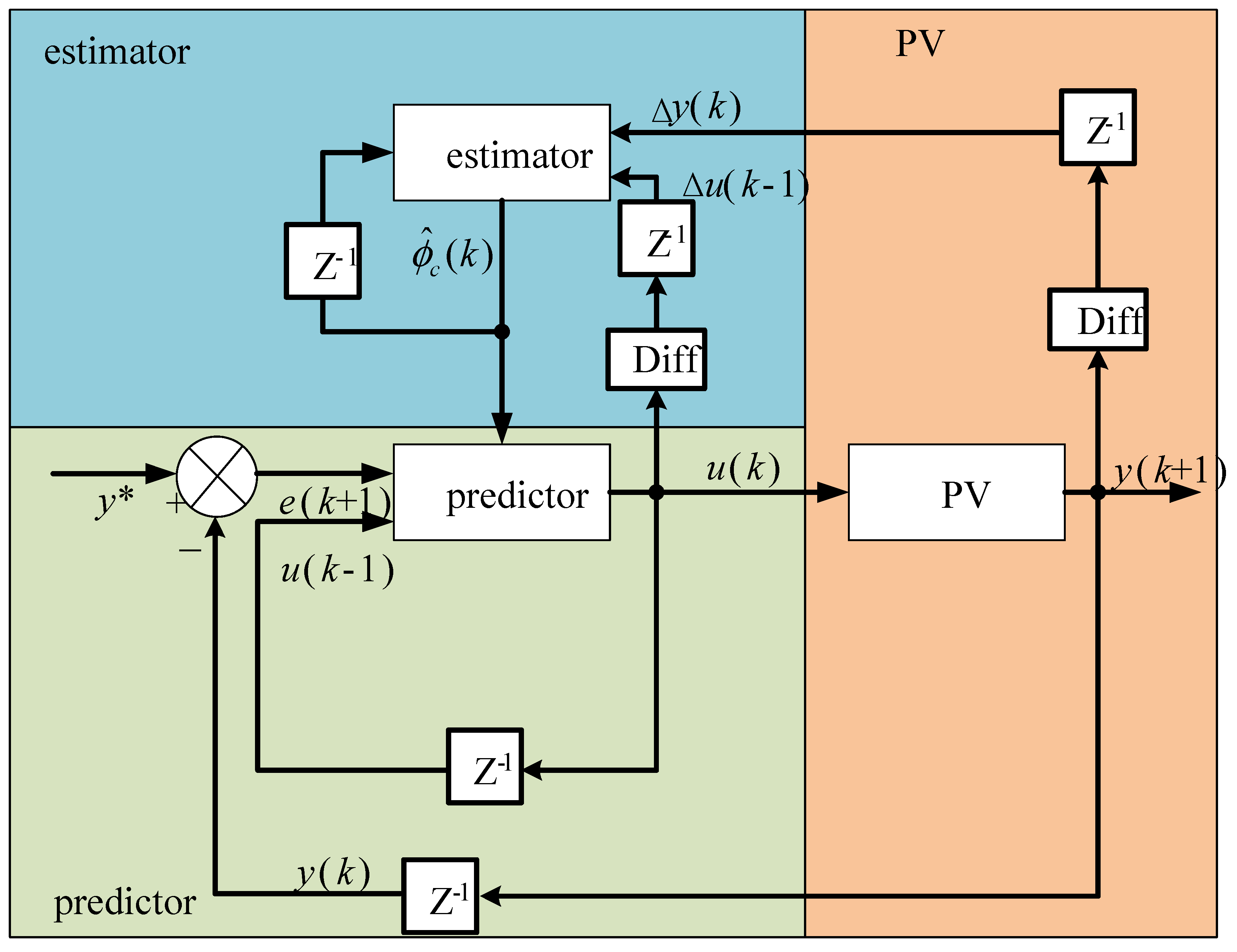
A schematic diagram of the MFAC-SSDC controller structure is shown in Figure 1. According to Figure 1, the MFAC-SSDC consists of two parts: the pseudo-partial derivative estimator and the predictor. Among them, the pseudo-partial derivative estimator updates the estimated value of the pseudo-partial derivative based on the input and output data of the current photovoltaic system. The predictor calculates the controller output u(k) based on the updated and the input–output data, and then applies it to the photovoltaic system.
Figure 1.
Schematic diagram of MFAC-SSDC structure.
According to Figure 1, the principle of the MFAC-SSDC controller suppressing sub-synchronous oscillations is as follows: First, at time k, the input u(k) generates y(k + 1) after passing through the photovoltaic system. The MFAC-SSDC controller acquires the current system output y(k + 1) and the previous input u(k). The estimator then calculates the pseudo-partial derivative using Δu(k − 1) and Δy(k). Meanwhile, the error e(k + 1) = y∗ − y(k) between the reference output and the actual output of the photovoltaic system is calculated, where the reference value y∗ is usually a constant variable under non-oscillatory operating conditions. The predictor estimates the dynamic characteristics of the photovoltaic system (the effect of the input variation Δu on the output) based on the pseudo-partial derivative , and computes the new control input u(k + 1) by combining the error e(k + 1) and u(k − 1). The new control signal u(k + 1) is then applied to the photovoltaic system. The photovoltaic system responds and generates a new output y(k + 2); y(k + 2) is fed back to the system as the input for the MFAC-SSDC controller in the next cycle. The above process is repeated to achieve continuous adaptive control.
2.2. System Dynamic Linearization Model
Photovoltaic systems can be regarded as single-input single-output discrete-time nonlinear systems described by the following model:
where: u(k), y(k) are the input and output of the system at time k; nu, ny are dimensions of the input and output; f() is an unknown nonlinear function.
The dynamic characteristics of the nonlinear system shown in Equation (1) are obtained by estimating its pseudo-partial derivative (PPD). Then, using the resulting PPD, a dynamic linearization model between the input and output of the system can be established. Depending on the linearization process, the existing dynamic linearization methods can be mainly classified into CFDL, PFDL, and FFDL. It is notable that the dynamic linearization data model used in CFDL is relatively simplified in structure, considering only the contribution of the change in input at the current sampling moment to the system output at the immediate next sampling moment. PFDL’s dynamic linearization data model introduces a sliding time window to consider the impact of input changes at the current and the previous L-1 moment on the output at the next moment, while FFDL’s dynamic linearization data model considers the impact of historical input and output changes on the output at the next moment. Among them, the CFDL model has the simplest structure and the lowest computational complexity, and is suitable for scenarios with high real-time requirements. Therefore, this paper selects the compact format linearization method CFDL to perform equivalent linearization on Equation (1). The system should satisfy the following two assumptions.
Assumption 1: The partial derivatives of the function f(ˑ) with respect to the input u(k) are continuous except for a finite number of time points.
Assumption 2: Except for finite time points, Equation (1) satisfies the generalized Lipschitz condition, that is:
where: b is a normal number.
Assumption 1 sets the typical constraint premise for a general nonlinear system, reflecting the essential limitations of such systems; Assumption 2 (Generalized Lipschitz Condition) further specifies that a bounded change in system input must lead to a bounded change in system output, which is a fundamental property satisfied by almost all practical industrial physical systems [26].
For the PV grid-connected system studied in this paper, its core is a grid-tied inverter system with closed-loop control, which is a typical physical system following objective circuit laws and energy conservation principles. From the perspective of dynamic characteristics: The mapping relationship between the control input of the system (the output of the additional damping controller) and the system output (the sub-synchronous component of the grid-connected current) is continuous and differentiable, and the partial derivative of the nonlinear mapping function with respect to the control input is continuous, which fully satisfies the requirements of Assumption 1.
The PV grid-connected system is an energy-bounded physical system. A bounded change in the control input will only cause a bounded dynamic response of the output electrical quantity, and there will be no unbounded jump in the output under finite input disturbances, which strictly conforms to the generalized Lipschitz condition defined in Assumption 2.
For the nonlinear system (1) satisfying Assumption 1 and Assumption 2, when ∣Δu(k)∣ ≠ 0 for all time k, there must exist a time-varying bounded parameter ∈ R, such that the system can be equivalently transformed into the CFDL incremental data model:
where: Δy(k + 1) = y(k + 1) − y(k) is the system output increment at adjacent times.
The complete proof of this lemma can be found in Ref. [27].
By substituting Δy(k + 1) = y(k + 1) − y(k) into Equation (3) and rearranging the terms, the final CFDL model of the system is obtained:
where: is the variation of the output at two adjacent times; ϕc(k) is the pseudo-partial derivative of the photovoltaic system.
Through the derivation of Equation (4), the photovoltaic system, which originally had an unknown exact model, was successfully transformed into an equivalent model with a linearized form. The model introduces dynamically updated pseudo-partial derivatives to capture the nonlinear dynamic characteristics of the system without relying on traditional physical mechanism modeling. The equivalent model contains neither the dynamic structure of the controlled system nor any physical parameters and is completely free from reliance on prior knowledge of the system. The construction and update of the model are based solely on real-time input-output data, which is a data-driven approach. Such methods mine dynamic patterns through data and are applicable to complex systems or scenarios with uncertain parameters, significantly enhancing the adaptability and robustness of control strategies.
2.3. Pseudo-Partial Derivative Estimator
The pseudo-partial derivative, as a key characterization of the dynamic characteristics of the system, has time-varying properties and its true value is difficult to obtain directly by measurement or analysis. Therefore, an online identification method is needed to estimate its current value in real time using the historical input and output data of the controlled object. The criterion function for estimating the pseudo-partial derivative is:
where: μ is the weighting factor, μ > 0. The rationale for selecting the criterion function in Equation (5) is as follows:
The first term is the estimation error term. It minimizes the deviation between the predicted and actual output of the photovoltaic grid-connected system, ensuring the accuracy of PPD estimation and the fidelity of CFDL model for the non-linear time-varying grid-connected system.
The second term is introduced to solve the ill-posed problem of PPD estimation in practical engineering: the photovoltaic grid-connected system is affected by grid strength fluctuation, non-linear disturbance and measurement noise, which may lead to sharp divergence of the unconstrained estimation results. This term constrains the variation of the estimated PPD between adjacent sampling steps, ensuring the stability of the estimation process.
The core function of the weight factor μ is to balance the accuracy and smoothness of the pseudo-partial derivative estimation. If the value of μ is too small, the smoothness will decrease significantly and the estimated value will fluctuate sharply; if the value of μ is too large, although extremely high smoothness can be obtained, it will lead to lag in the update of the estimated value.
Regarding finding the extremum of in Equation (5), the algorithm for estimating the pseudo-partial derivative is:
where: η is the step factor. η ∈ (0, 2].
In order to enhance the tracking ability of the estimation algorithm for time-varying parameters, the following algorithm reset mechanism needs to be introduced:
where: ε is a sufficiently small positive number, is the initial value of .
The pseudo-partial derivative parameter of the system shows a relatively simple dynamic variation characteristic, which is manifested as a parameterized quantity with slow time-varying characteristics. The value of this parameter depends on factors such as the system’s intrinsic dynamic characteristics, the operating point of the closed-loop operation, and the way the control input signal acts. Even though the system itself is significantly time-varying in terms of structure, order, delay, or physical parameters, the pseudo partial derivatives show little variation in output behavior, demonstrating strong robustness and stability. This characteristic enables data-driven control methods based on pseudo-derivative modeling to effectively achieve high-performance control of complex time-varying dynamic processes even in the absence of an exact mathematical model of the system.
2.4. Predictor
The predictor uses the pseudo-partial derivative estimator provided by the pseudo-partial derivative estimator, combined with the historical input data of the photovoltaic system, the historical output data, and the expected output target, to derive the control instruction u(k) at the current moment in real time, so that the output y of the system keeps approaching the output target value y*.
One-step prediction error control algorithms in discrete-time systems face inherent flaws: the minimum error criterion poses the risk of saturating the control signal and undermining system stability; The weighted error criterion, however, has the shortcomings of static error after convergence and limited accuracy [27]. Therefore, the control input criterion function is constructed as follows:
where: y* is the expected system output value, λ is a weighting factor used to suppress the variation of the control input quantity and ensure that the control input signal has a certain degree of smoothness. Selecting an appropriate one can both ensure the stability of the controlled system and achieve better output performance.
Substitute Equation (4) into the performance index (8). Since all variables in the discrete-time system are real numbers, the absolute value square can be directly rewritten as the square form, and the performance index is transformed into:
To obtain the optimal control input u(k) that minimizes , we take the first-order partial derivative of with respect to u(k) according to the extreme value condition of the convex quadratic function:
For the convex quadratic performance index, the first-order partial derivative equal to zero is the necessary and sufficient condition for the global minimum. Let divide both sides of the equation by 2, and expand and sort out the formula:
Move the tracking error term to the right side of the equation, and solve for the control input increment:
In practical engineering applications, to ensure the bounded-input bounded-output stability and robustness of the closed-loop system, avoid excessive overshoot and abrupt change of the control input, step factors ρ0 ∈ (0, 1] and ρ1 ∈ (0, 1] are introduced into the control law. In addition, since the PPD is unknown and needs to be estimated online in real time, the estimated value is used in the actual control algorithm. Finally, the MFAC control law is obtained as:
Combined with Equations (6), (7) and (14), the proposed scheme forms the MFAC-SSDC algorithm for suppressing sub-synchronous oscillations. From the above three formulas, it can be seen that the CFDL data model is entirely dependent on the input and output data collected in real time by the closed-loop system for controller design, and neither contains nor implies any mathematical model information that describes the dynamic behavior of the controlled object. Meanwhile, because pseudo-partial derivatives have a strong tolerance for uncertainties in the system such as time-varying parameters, structural changes, phase shifts, and hysteresis, the MFAC method based on the CFDL model shows good robustness and adaptability when dealing with complex dynamic uncertainties.
Specifically, MFAC belongs to the category of data-driven control. Its design process relies minimally on an accurate mathematical model of the controlled system. Unlike model-based control methods that demand precise system parameters and structure, MFAC only relies on input-output data to realize adaptive control, thus avoiding the complexity and inaccuracy caused by model identification. The core idea of the method is to transform a complex discrete-time nonlinear system into a virtual, equivalent time-varying linear data model by means of dynamic linearization, using pseudo partial derivatives or pseudo-gradients. This modeling approach not only provides a clear framework for the design of the controller, but also enables the system to maintain stable and efficient performance in the face of multiple operating conditions and uncertain disturbances, an advantage that is difficult to achieve with traditional model-based control strategies.
3. MFAC-SSDC Access Location and MFAC-SSDC Parameter Design
3.1. MFAC-SSDC Access Location
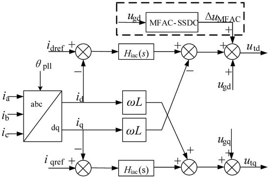
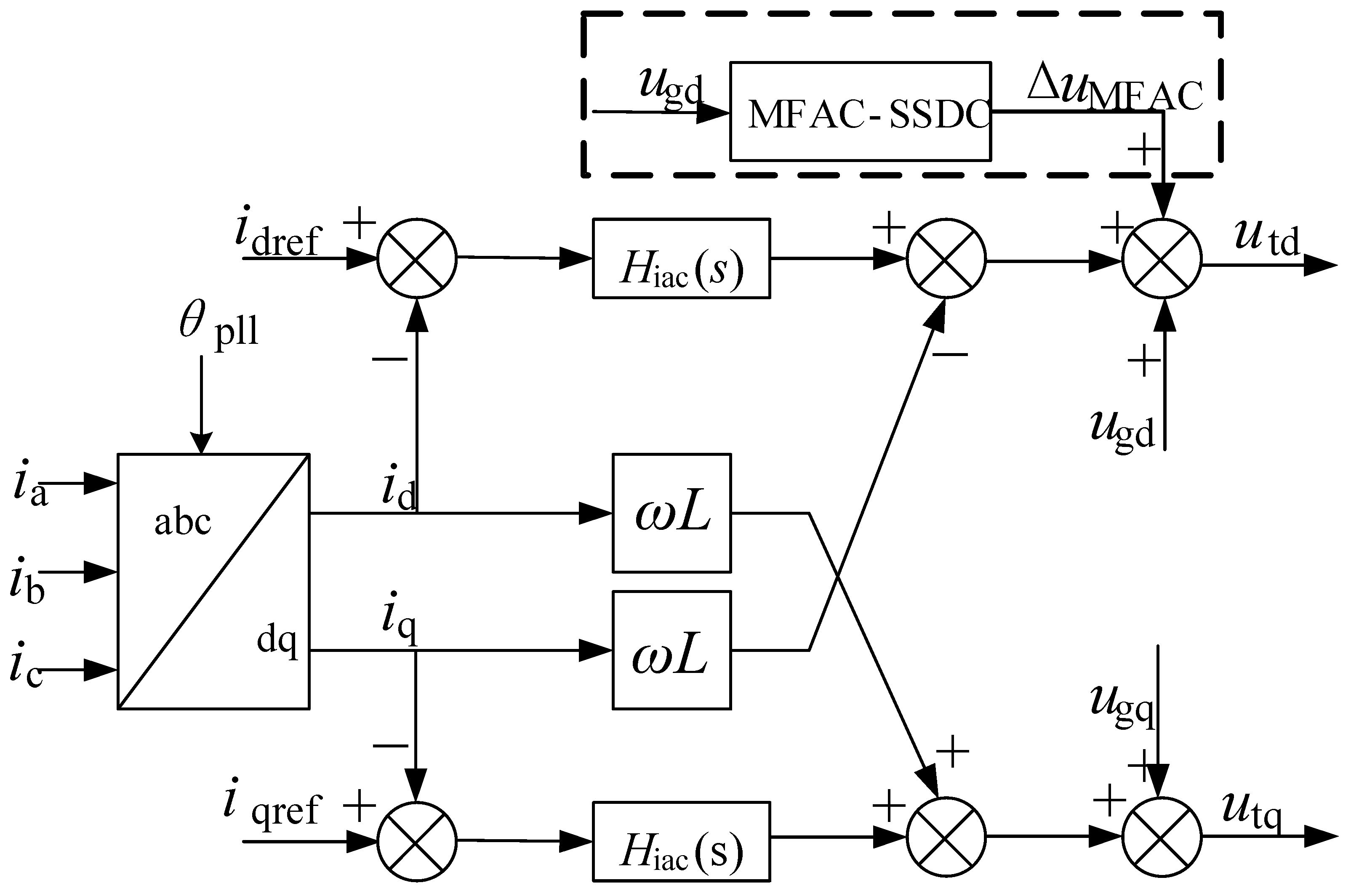
Figure 2 shows the access position of the inverter current inner loop control circuit and the MFAC-SSDC controller in the photovoltaic grid-connected system. Among them, ugd and ugq are the d-axis and q-axis components of the grid voltage; igdref and igqref are reference values for the d-axis and q-axis components of the grid current; igd and igq are the d-axis and q-axis components of the grid connected current; θpll is the lock-in angle output by the phase-locked loop. Hiac(s) is the transfer function of the current inner loop.
Figure 2.
MFAC-SSDC Access Location.
- Specifically, Hiac(s) corresponds to the d-axis and q-axis proportional-integral control loops of the current inner loop, which is defined as:
Under normal circumstances, synchronize the rotation of the coordinate system d-axis to locate the grid connection point voltage vector, which will result in the q-axis component ugq of the grid connection point voltage being zero and having no reference significance. At the same time, the d-axis of the current inner loop directly affects the active power of the grid connection point. Therefore, this paper selects the d-axis component ugd of the grid connection point voltage of the photovoltaic grid connection system as the input signal of MFAC-SSDC, and the output ΔuMFAC of MFAC-SSDC is added to the output terminal of the d-axis current inner loop.
3.2. MFAC-SSDC Parameter Design
For the MFAC-SSDC controller mentioned above, the parameters that need to be optimized are , which have a significant impact on the control performance of MFAC-SSDC. Specifically, the key parameter that balances the feedback strength and numerical stability of λ directly affects the amplitude of the control variable. If λ is too small, the system response is too sensitive, and the unit error causes excessive control adjustments, leading to high-frequency oscillations and even system instability. If λ is too large, the control action is too conservative, which suppresses the system’s response ability to errors, resulting in sluggish response, prolonged adjustment time, and even inability to eliminate steady-state errors. μ mainly limits the rate of change of pseudo partial derivatives to prevent drastic parameter fluctuations caused by dynamic changes in the system, thus smoothing the control process. If μ is too small, the estimated value of pseudo partial derivatives will change too dramatically, resulting in frequent and significant fluctuations in the control quantity, a decrease in system stability, and possible sustained oscillations. If μ is too large, parameter changes will be excessively restricted, making it difficult for the controller to adapt to dynamic changes in the system, and the adaptive ability will be weakened. When facing load changes and other working conditions, the response will lag. η controlling the update speed of pseudo partial derivatives determines the speed at which the system learns new dynamic characteristics. If it is too small, it can lead to slow learning speed and prolonged convergence process. If it is too large, it can cause the learning process to be too aggressive, which may result in parameter estimation oscillations or even divergence. The update rate of ρ0 and ρ1 control variable affects the dynamic response characteristics of the system. If its value is too small, it can cause the system to respond slowly and the correction of errors to be too slow, resulting in prolonged adjustment time and increased overshoot. If its value is too large, it can cause excessive changes in the control variable, which may lead to system oscillation. is a real-time estimation of the dynamic characteristics of the system, reflecting the degree of impact of input changes on output, and is the core of MFAC to achieve “model free” control. Inaccurate estimation of its value can lead to errors in control quantity calculation, manifested as increased tracking error, abnormal system response, and even instability. is the initial value of . The parameter constraints to be optimized mentioned above are:
In order to quantitatively evaluate the dynamic suppression effect of the proposed MFAC-SSDC on sub synchronous oscillations and optimize controller parameters, appropriate performance indicators are crucial. Time weighted mean square error integral (ITSE) is a compromise measure between squared error integral (ISE) and absolute time error integral (ITAE). It retains the fast convergence characteristics of ISE while overcoming the slow response problem of ITAE. This makes ITSE particularly suitable for characterizing transient processes in grid connected systems, which is crucial for achieving effective oscillation suppression. Therefore, this article chooses ITSE performance indicators as the objective function, and its calculation formula is defined as:
where: t1 is the time when the controller is put into operation; t2 is the time when the controller switches out; e(t) = y* − y(t), e(t) is the difference between the system output reference value and the actual value.
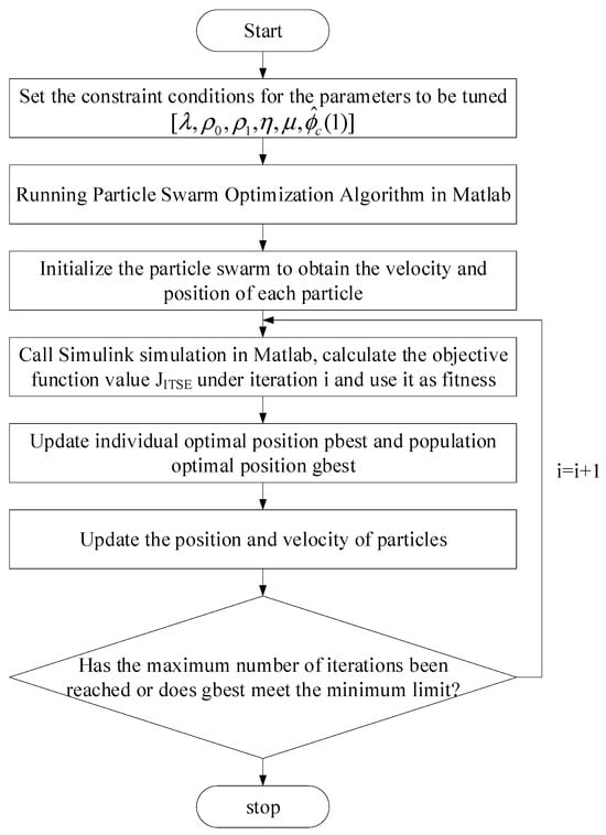
With the minimum value of the objective function as the optimization objective, the particle swarm optimization algorithm is used to optimize the above parameters, as shown in Figure 3. The population density is set to 20, the number of iterations is set to 20, the inertia weights of the 6 parameters are set to a fixed value of 0.75, the self-learning factor is set to 1.5, the group learning factor is set to 2, the simulation step size is set to 1 × 10 −5 s, and the convergence standard is set to 0.005.
Figure 3.
Controller Parameter Optimization Flowchart.
4. Case Analysis
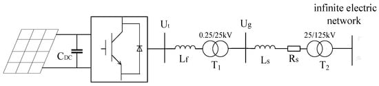
Build a simulation model of the photovoltaic grid-connected system in the Matlab /Simulink (R2022b) environment based on the topology shown in Figure 4. The model mainly consists of a photovoltaic array, DC-side capacitors, inverters, filters, two step-up transformers and transmission lines. The photovoltaic is first raised to the grid connection point voltage by a 0.25/25 kV step-up transformer, and then connected to the AC grid through a 25/125 kV step-up transformer and transmission line. The key parameters of the photovoltaic grid-connected system are shown in Table 1.
Figure 4.
Photovoltaic grid connected system model.
Table 1.
Parameters of Photovoltaic Grid connected System.
For the photovoltaic system in Figure 4, this paper verifies the sub-synchronous oscillation suppression performance of MFAC-SSDC through multiple time-domain simulation cases.
4.1. Example 1: Verifying the Effectiveness of MFAC-SSDC in Suppressing SSO
The initial operating conditions of the photovoltaic system are as follows: The photovoltaic output is 0.86 pu; The short-circuit ratio is 3.17; The proportional coefficient Kp1 of the voltage outer loop is 3, and the integral coefficient Ki1 is 800; The d-axis current inner loop has a proportional coefficient Kp2 of 0.3 and an integral coefficient Ki2 of 20. At 0.5 s, Kp2 is reduced to one-fifth of its original value and Ki2 is increased by a factor of 15, at which point SSO occurs in the photovoltaic system. MFAC-SSDC optimizes the control parameters based on this operating point, and the optimal parameters obtained using the optimization algorithm proposed in Section 3 are shown in Table 2.
Table 2.
MFAC-SSDC Controller Parameters.
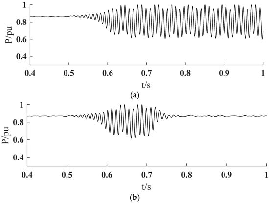
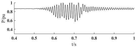
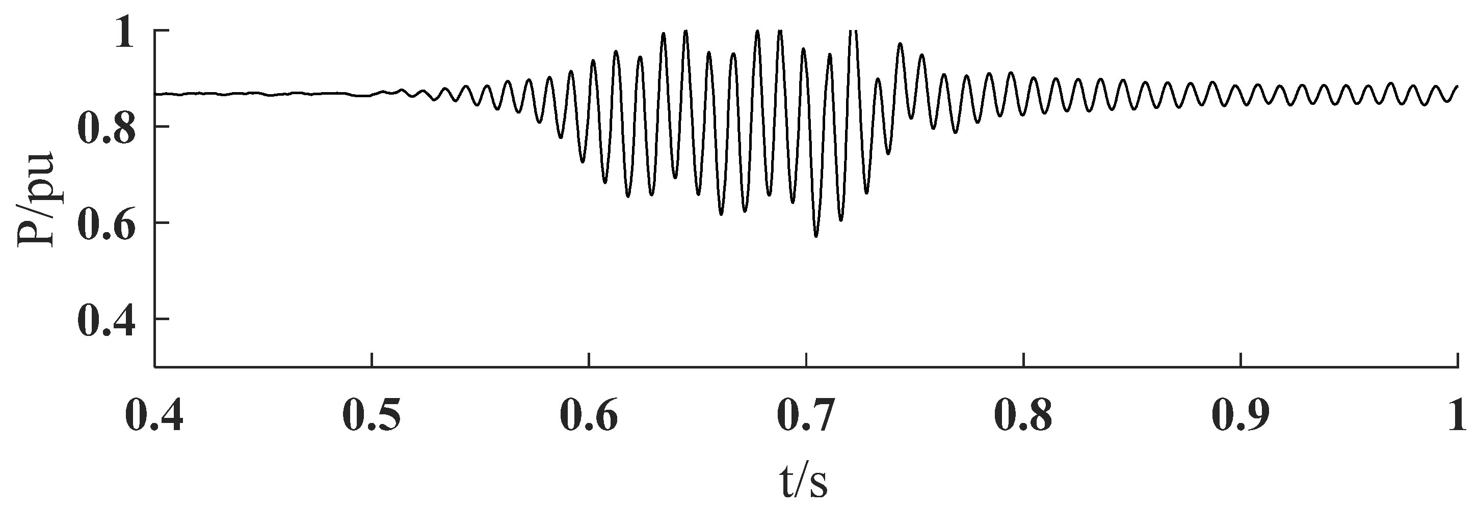
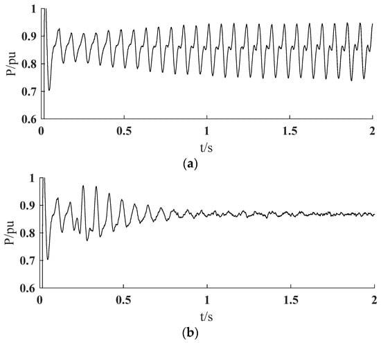
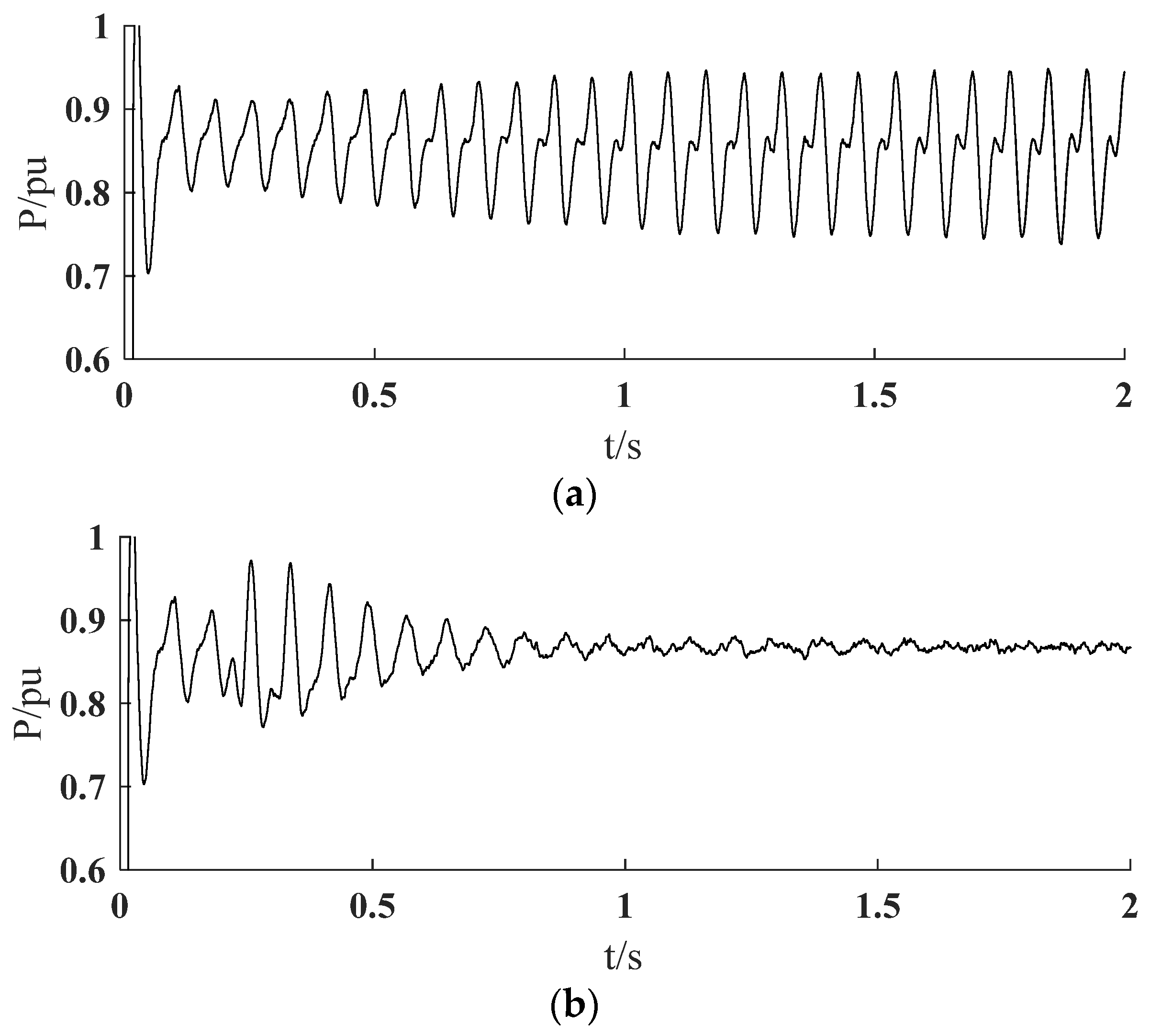
When the MFAC-SSDC controller is added at 0.7 s, the time-domain waveforms of the active power output P of the photovoltaic system before and after the addition of the MFAC-SSDC controller were obtained as shown in Figure 5.
Figure 5.
Inhibition effect of MFAC-SSDC: (a) Controller-less; (b) MFAC-SSDC.
According to Figure 5, the photovoltaic system remained in normal operation until 0.5 s, and at 0.5 s, changing the parameters of the inner loop of the d-axis current caused significant oscillations in the output active waveform. However, when MFAC-SSDC is added at 0.7 s, the setting time is 0.07 s. After 0.77 s, the active waveform returns to its pre-oscillation state and the oscillation does not recur.
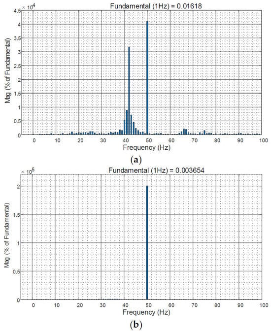
Figure 6 presents the FFT analysis results of the current at the A-phase parallel point before and after the addition of MFAC-SSDC. According to Figure 6, in the absence of A controller, the A-phase parallel point current has a 42 Hz sub-synchronous oscillation component in addition to the fundamental frequency component; After the MFAC-SSDC is put into operation, the 42 Hz oscillation component is suppressed, leaving only the fundamental frequency component. Therefore, the proposed MFAC-SSDC can effectively suppress SSO.
Figure 6.
FFT analysis results of the grid-connected point current at a single oscillation frequency: (a) Without controller; (b) MFAC-SSDC control.
4.2. Example 2: Verifying the Adaptability of MFAC-SSDC
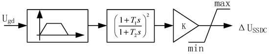
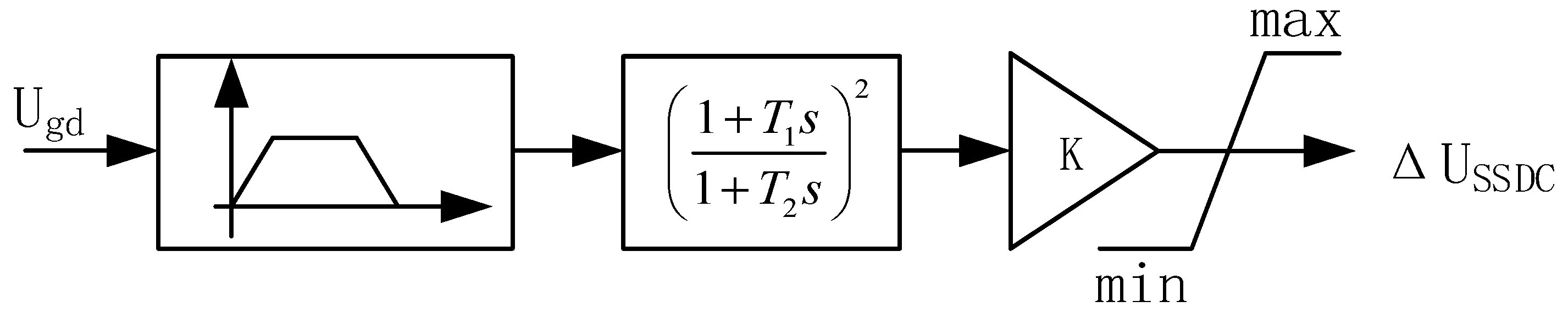
Using the operating point mentioned above as the base point, different oscillation frequencies are obtained by changing the grid strength, photovoltaic output, the proportional coefficient Kp1 of the voltage outer loop, and the integral coefficient Ki1; At the same time, the proposed MFAC-SSDC was compared with the traditional additional damping controller (C-SSDC) based on the phase compensation principle to verify the advantages of the MFAC-SSDC in terms of adaptation. The structure of the C-SSDC is shown in Figure 7.
Figure 7.
Structure diagram of C-SSDC controller.
The controller access position and input signal of C-SSDC are kept the same as those of MFAC-SSDC. The C-SSDC consists of components such as filtering, phase shifting, gain, and limiting. First, the filtering section consists of a DC-blocking section and a low-pass filter connected in series. In this paper, the cut-off frequency of the DC-blocking section is set to 39.5 Hz, and the cut-off frequency of the low-pass filter is set to 44.5 Hz; The phase shift consists of two identical phase shifters, mainly to achieve phase compensation for the filtered components; The gain link provides gain compensation The gain in this paper is 0.4. The limiting stage restricts the amplitude of the additional damping signal to no more than 50% of the voltage reference value. Phase shifter parameters T1 and T2 are set using the following formula:
where: is the oscillation frequency of the input signal; is the phase of the phase to be compensated in the system.
The phase to be compensated by the system is −30.1°, so each phase shifter compensates for −15.05°. The phase shifter parameters obtained according to Equation (18) are shown in Table 3:
Table 3.
C-SSDC Phase Shifter Parameters.
The sub-synchronous oscillations at different frequency points are obtained by changing the grid strength, photovoltaic output P, the proportional coefficient Kp1 of the voltage outer loop, and the integral coefficient Ki1 based on the operating point A, as shown in Table 4. Set the time to add disturbances at 0.5 s and the controller’s input time at 0.7 s. The suppression effects of C-SSDC and MFAC-SSDC on different oscillation frequencies of SSO are compared respectively at the operating points of A–C.
Table 4.
Oscillation frequency under different parameters.
The strength of the grid connection is generally measured by the Short-Circuit Ratio (SCR), which is defined as follows:
where: UN is the rated voltage at the PV grid connection point, SN is the rated system capacity, and Zs is the equivalent grid impedance.
Figure 8 shows the active power waveform at the grid connection point when C-SSDC is put into operation at point A. It can be seen from Figure 8 that after C-SSDC is activated, it takes a relatively long time to completely suppress the oscillation, and the active power fluctuates within a small range. Compared with the MFAC-SSDC in Figure 5, although the C-SSDC has A slower suppression speed than the MFAC-SSDC, it still has a satisfactory suppression effect on the oscillation at operating point A.
Figure 8.
Inhibition effect of C-SSDC at operating point A.
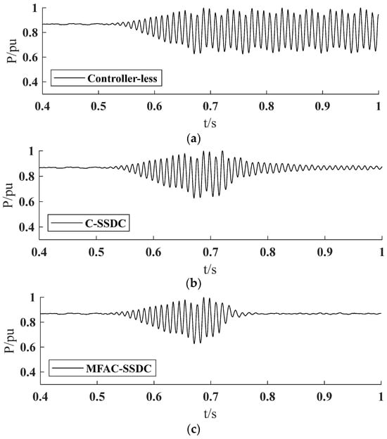
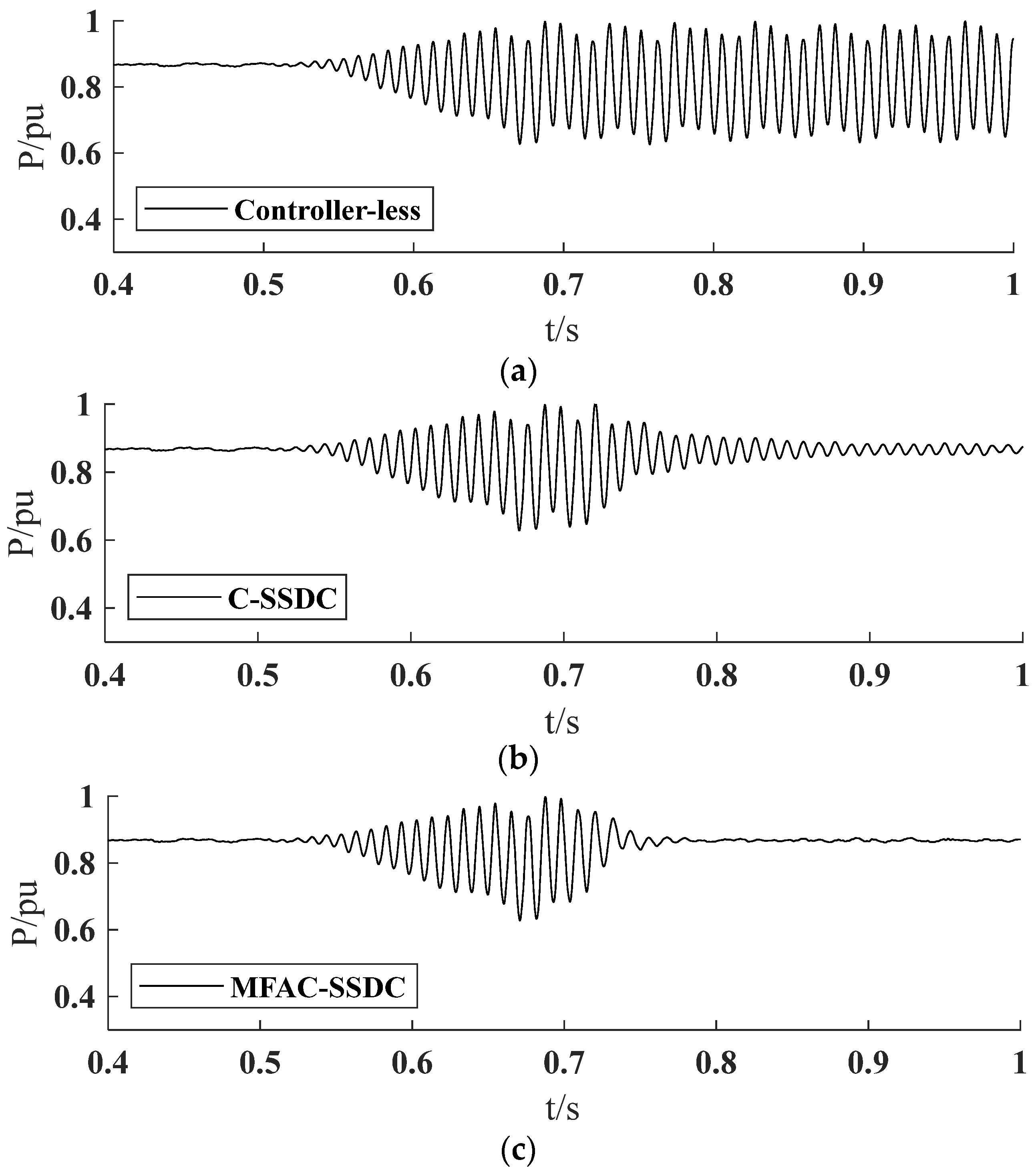
Figure 9 shows the active power waveforms at the parallel point of uncontrolled, C-SSDC and MFAC-SSDC at operating point B. As shown in Figure 9, C-SSDC still has a relatively obvious damping effect on oscillation at operating point B; The MFAC-SSDC still suppresses sub-synchronous oscillations within a very short time after being activated, and there is no fluctuation in active power after the oscillation is suppressed.
Figure 9.
Inhibition effects between MFAC-SSDC and C-SSDC at operating point B: (a) Controller-less; (b) C-SSDC; (c) MFAC-SSDC.
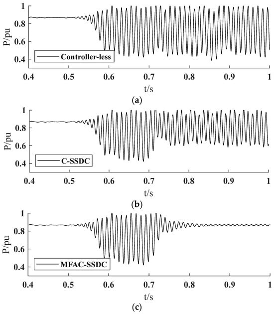
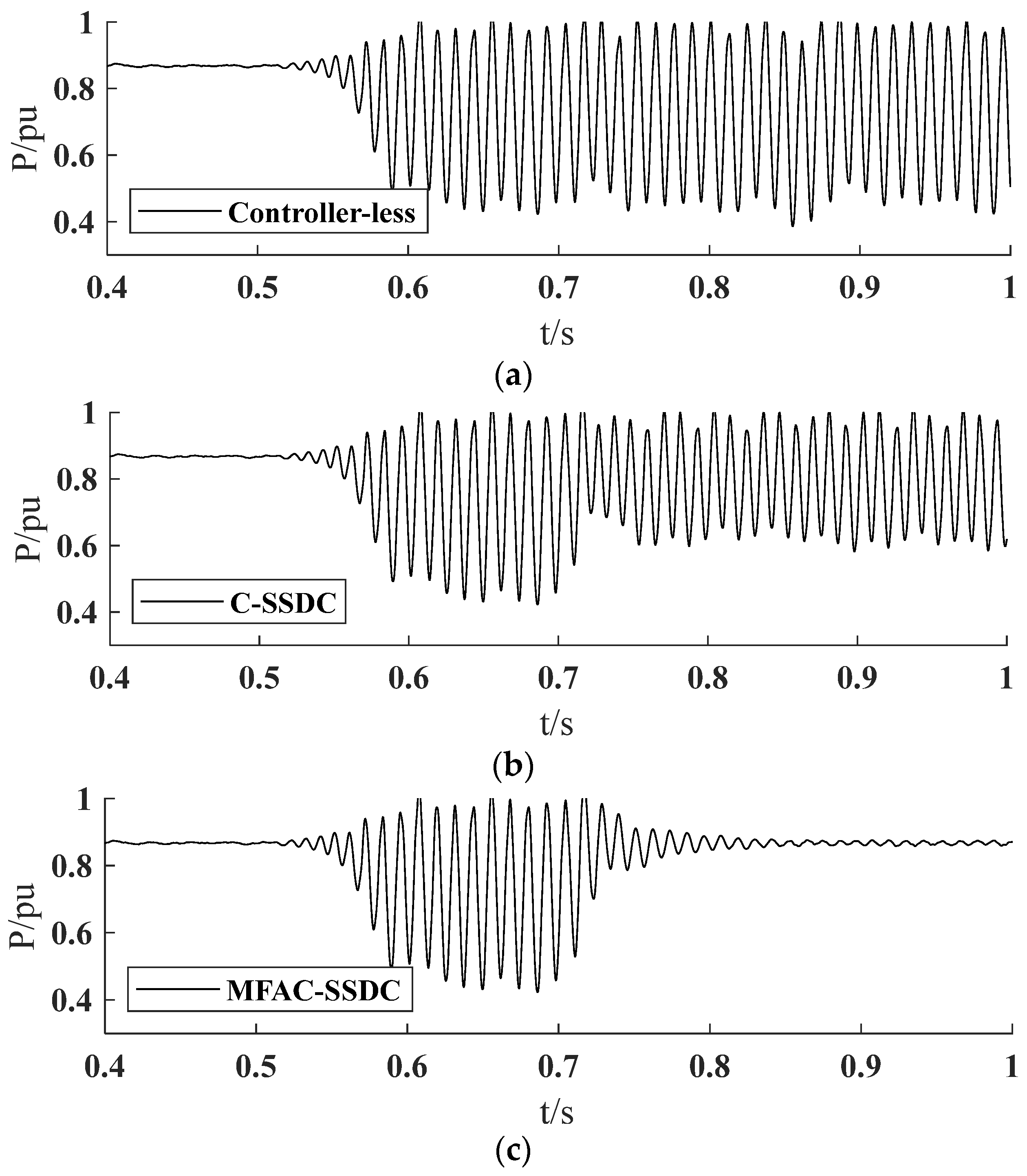
Figure 10 shows the active power waveforms at the parallel point of uncontrolled, C-SSDC and MFAC-SSDC at operating point C. Since the oscillation frequency at operating point C is 32 Hz, the oscillation frequency has shifted significantly compared to operating point A, and the compensation angle of C-SSDC may deviate from the optimal compensation angle, resulting in a significantly weakened oscillation suppression effect; While the MFAC-SSDC still maintains a good suppression effect on oscillations, it achieves the suppression of sub-synchronous oscillations in a very short time after being activated. In summary, by comparing the suppression effects of MFAC-SSDC and C-SSDC on SSO at operating points A–C, it can be concluded that the MFAC-SSDC proposed in this paper has stronger adaptability and can suppress sub-synchronous oscillations of different oscillation frequencies.
Figure 10.
Inhibition effects between MFAC-SSDC and C-SSDC at operating point C: (a) Controller-less; (b) C-SSDC; (c) MFAC-SSDC
4.3. Example 3: Consider the Suppression of SSO at Multiple Oscillation Frequencies
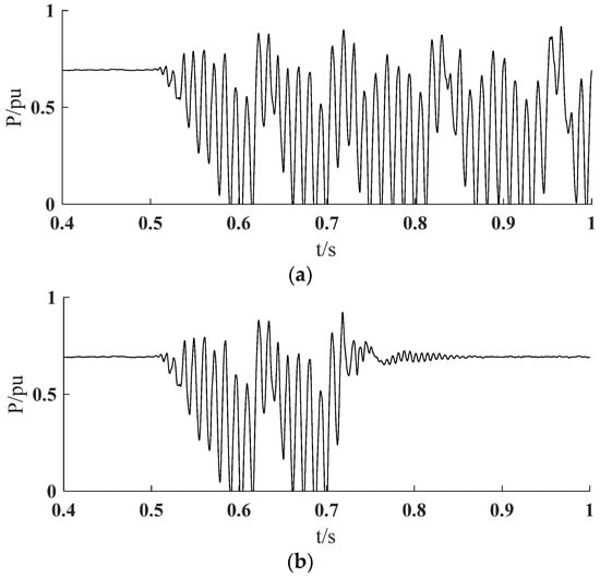
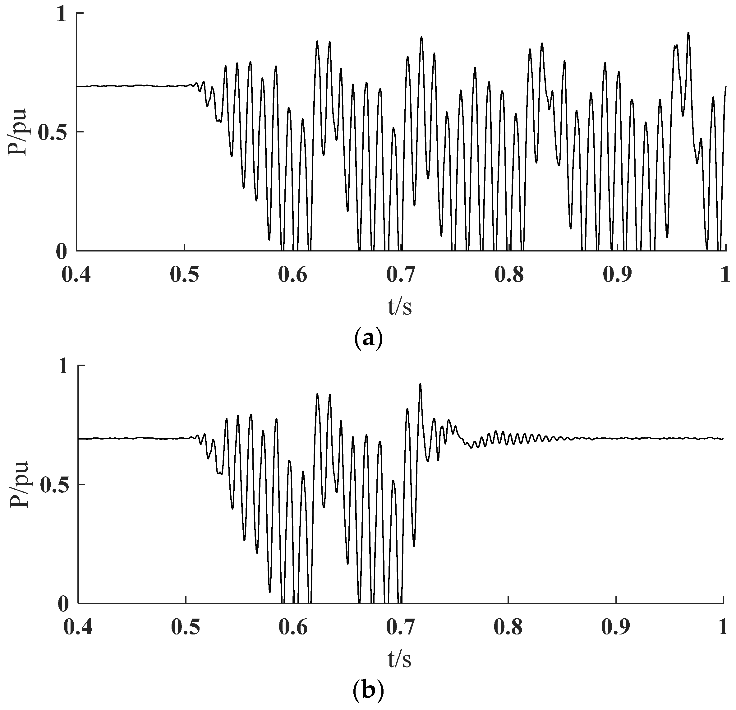
Example 2 discusses the damping effect of MFAC-SSDC on SSO under different parameters, but both are for a single oscillation frequency. This section will discuss the inhibitory effect of MFAC-SSDC on multiple oscillation frequencies. The initial operating conditions of the photovoltaic system are as follows: Photovoltaic output is 0.69 pu; The short-circuit ratio is 3.17; The proportional coefficient Kp1 of the voltage outer loop is 3, and the integral coefficient Ki1 is 800; The d-axis current inner loop has a proportional coefficient Kp2 of 0.3 and an integral coefficient Ki2 of 20. At 0.5 s, Kp2 is reduced to one-fifth of its original value and increase Ki2 is increased by a factor of 50, at which point SSO occurs in the photovoltaic system. The controller uses the parameters in Table 2, and the active power waveforms before and after the controller is added are shown in Figure 11.
Figure 11.
Suppression Effect of MFAC-SSDC at Multiple Oscillation Frequencies: (a) Controller-less; (b) MFAC-SSDC.
As shown in Figure 11, the photovoltaic system changed the parameters of the inner loop of the d-axis current at 0.5 s, causing significant oscillations in the output active waveform. But when MFAC-SSDC is added at 0.7 s, the oscillation is suppressed for a short time, and the active waveform returns to the state before the oscillation.
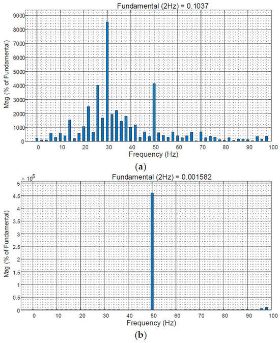
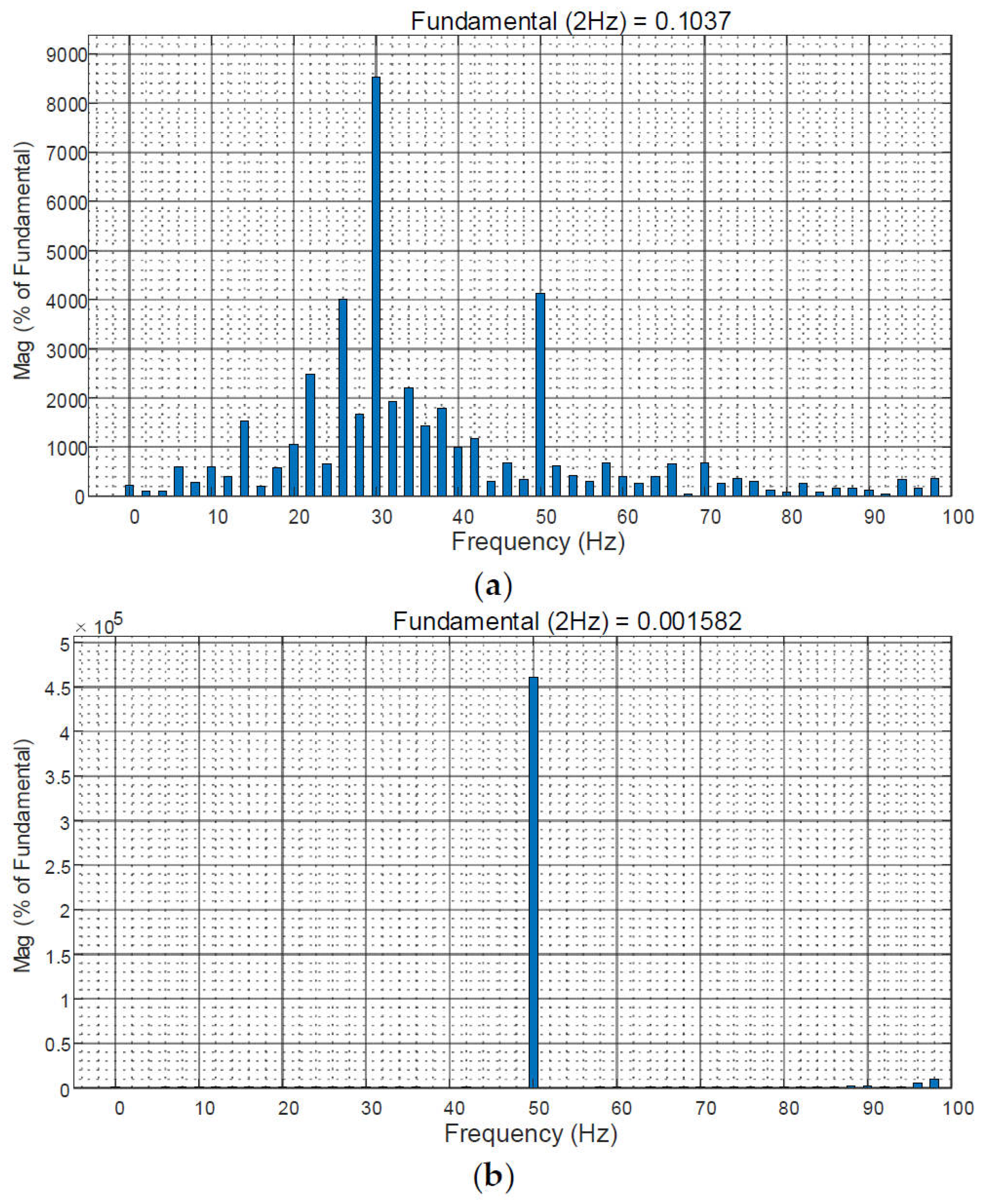
Figure 12 shows the FFT analysis results for the A-phase parallel point current between 0.5–1 s and 1–1.5 s before the addition of the MFAC-SSDC. According to Figure 12, in the absence of the controller, in addition to the fundamental frequency component, there are 32 Hz and 26 Hz sub-synchronous oscillation components in the A-phase parallel point current. After the MFAC-SSDC is activated, the 32 Hz and 26 Hz oscillatory components are suppressed, leaving only the fundamental frequency component. Therefore, the proposed MFAC-SSDC also has a good damping effect on SSO at multiple oscillation frequencies.
Figure 12.
FFT analysis results of the grid-connected point current under multiple oscillation frequencies: (a) Without controller; (b) MFAC-SSDC control.
The mechanism behind the increase in oscillation frequency when Ki2 increases significantly is as follows. When the integral coefficient Ki2 of the d-axis current loop increases moderately, the phase lag of the controller is limited, and only one dominant sub-synchronous mode in the system satisfies the oscillation conditions in terms of phase and gain, thus resulting in single-frequency oscillation. With a substantial increase in Ki2, the phase lag of the current loop increases significantly, and the control gain is greatly enhanced over a wide frequency range, which excites multiple originally weakly damped sub-synchronous modes in the system, eventually leading to multi-frequency sub-synchronous oscillations.
4.4. Example 4: Consider the Suppression of SSO for Different Oscillation Mechanisms
In photovoltaic grid-connected systems, the core function of the phase-locked loop is to detect the voltage phase at the grid connection point and provide an accurate phase reference for inner loop control, which is crucial for the stable operation of the system. However, the presence of the oscillation mode of the phase-locked loop poses a serious threat to the stability of the power system. Therefore, this section will explore the suppression effect of MFAC-SSDC on SSO caused by phase-locked loops.
First, improper parameter setting of the phase-locked loop is the main cause of PLL-SSO, while insufficient grid strength is another key factor inducing PLL-related oscillations. Therefore, by reducing Kp4 by a factor of 1.84 and increasing Ki4 by a factor of 2.5, the grid strength is reduced to 1.33, causing PLL-SSO to occur in the system.
The dynamic characteristics of the system are differ significantly because the oscillations caused by the phase-locked loop and those caused by the current inner loop have different oscillation mechanisms. The output pseudo-partial derivative of the MFAC-SSDC estimator is used to estimate the dynamic characteristics of the system. Although the pseudo-partial derivatives can be updated adaptively, they cannot accurately estimate the system dynamics within a short time, which leads to the predictor not being able to output appropriate additional signals and degrades the suppression performance of the MFAC-SSDC. Therefore, the control parameters of the MFAC-SSDC need to be reoptimized, with the controller input time set at 0.2 s and the access position of the MFAC-SSDC remaining unchanged. Under the operating conditions mentioned above, the parameters were optimized using the optimization algorithm described in Section 3, and the optimized results are shown in Table 5.
Table 5.
MFAC-SSDC Controller Parameters for PLL-SSO.
After using the controller parameters in Table 5 for the MFAC-SSDC, the waveforms of the active power at the grid connection point before and after the MFAC-SSDC was put into operation are shown in Figure 13.
Figure 13.
Inhibition effect of MFAC-SSDC on PLL-SSO: (a) Controller-less; (b) MFAC-SSDC.
According to Figure 13, after the addition of MFAC-SSDC, oscillations are significantly suppressed, active power fluctuated only in a very small range for approximately 1 s, and active power tended to stabilize after 1.6 s. It can be seen that MFAC-SSDC is also capable of suppressing SSO caused by different oscillation mechanisms.
The reasons for the large difference in parameters between Table 2 and Table 5 are as follows: The significant differences in the optimized MFAC parameters for SSO induced by the current inner loop and PLL-induced SSO essentially reflect the optimal matching of control parameters to the dynamic characteristics of different controlled plants. Taking λ as an example, as a key parameter that balances control response speed and control signal smoothness, the weighting factor λ must be adjusted according to the bandwidth of the oscillation source and the sensitivity of the controlled loop to control disturbances. For the fast-dynamic current inner loop, a smaller λ ensures rapid suppression of oscillations; for the slow-dynamic PLL, which is sensitive to signal fluctuations, a larger λ guarantees the smoothness of damping injection and the stability of the phase-locking process.
It should be noted that the basic MFAC scheme adopted in this paper cannot automatically detect the essential change of the SSO oscillation mechanism and trigger the re-optimization of global control parameters. As a data-driven control method, MFAC realizes adaptive control only through online PPD estimation under fixed control parameters, which can cope with small dynamic perturbations of the system under the same oscillation mechanism, but cannot actively identify the switching of dominant oscillation sources (e.g., from the current inner loop to the phase-locked loop) or complete automatic global parameter tuning. The automatic detection of oscillation mechanism changes and closed-loop parameter self-optimization will be the core content of our follow-up research to further improve the engineering adaptability of the proposed control scheme.
5. Conclusions
This paper focuses on SSO problem in grid-connected photovoltaic systems, and proposes a model-free adaptive control based supplementary damping controller embedded in the inverter control loop. The main conclusions of this work obtained through time-domain simulation verification are summarized as follows:
- Strong robustness and adaptability: In terms of overall control performance, the proposed model-free adaptive controller outperforms the traditional additional damping controller based on phase compensation. It possesses stronger operational adaptability, and can effectively suppress sub-synchronous oscillations of photovoltaic grid-connected systems under different oscillation frequency operating conditions, showing good frequency adaptability.
- Multi-frequency oscillation suppression: In terms of multi-frequency oscillation suppression capability, the designed MFAC-SSDC achieves ideal suppression effects on both single-frequency and multi-frequency sub-synchronous oscillations, breaking through the limitation that traditional controllers can only be designed for single oscillation frequency.
- Different-mechanism oscillation suppression: MFAC-SSDC can maintain a desirable suppression effect on sub-synchronous oscillations under different oscillation mechanisms. Nevertheless, this method has obvious limitations: since the dynamic characteristics of the system differ significantly under different oscillation mechanisms, and the pseudo-partial derivative varies slowly, the controller parameters must be re-optimized for different working conditions, which weakens its real-time adaptability in complex and variable operating scenarios.
To further improve the performance of model-free adaptive damping control, future research can focus on developing an adaptive parameter tuning mechanism that can automatically adjust the controller parameters online according to operating conditions and oscillation characteristics, so as to achieve stronger universality and higher robustness without manual re-optimization.
Author Contributions
Conceptualization, C.Z. (Chaojun Zheng); methodology, C.Z. (Chenyang Zhao) and X.Y.; formal analysis, C.Z. (Chaojun Zheng); investigation, C.Z. (Chaojun Zheng) and X.Y.; data curation, C.Z. (Chenyang Zhao) and X.Y.; writing—original draft preparation, C.Z. (Chenyang Zhao); writing—review and editing, X.Y. All authors have read and agreed to the published version of the manuscript.
Funding
This study is funded by the National Natural Science Foundation of China (No. 52177098) and the Shanghai Engineering Research Center of Electric Power Artificial Intelligence (No. 19DZ2252800).
Data Availability Statement
The data used in this article have been given in detail in the article for the reader’s reference.
Acknowledgments
The authors are extremely grateful to each of the authors who have helped and contributed to this paper. It is their joint efforts that made this paper successfully published.
Conflicts of Interest
The authors declare no conflicts of interest.
References
- Ling, S.; Liu, R.; Wang, X.; Li, S. Restraining Method of SSO Based on Inertia and Damping Cooperative Control for VSG. Power Electron. Technol. 2025, 59, 113–118. [Google Scholar]
- Jing, X.; Zhao, Y.; Kong, W.; Li, S. Broadband Oscillation problem in New Power Systems. Electr. Technol. 2024, 18, 77–79. [Google Scholar]
- IEEE Subsynchronous Resonance Working Group of the System Dynamic Performance Subcommittee Power System Engineering Committee. Terms, Definitions and Symbols for Subsynchronous Oscillations. IEEE Power Eng. Rev. 1985, PER-5, 37. [Google Scholar]
- Hong, W.; Peng, G.; Tao, Z. Study of Sub-synchronous Oscillation Absorber for Wind Power Weak Grid. Power Electron. Technol. 2023, 57, 92–95. [Google Scholar]
- Cheng, J.; Su, L.; Yue, L. Power System Broadband Oscillation Risk Identification And Suppression For New Energy Access. J. Sol. Energy 2023, 44, 565–574. [Google Scholar]
- Jiang, Q.; Wang, Y. Overview of the Analysis and Mitigation Methods of Electromagnetic Oscillation in Power Systems With High Proportion of Power Electronic Equipment. Chin. J. Electr. Eng. 2020, 40, 7185–7201. [Google Scholar]
- Yu, X.; Wu, J.; Wang, B.; Liu, S. Wideband oscillation suppression strategy of direct-drive wind farms based on coordination between impedance sensitivity and additional control. J. Electr. Power Sci. Technol. 2025, 40, 256–268. [Google Scholar]
- Touti, E.; Abdeen, M.; El-Dabah, M.A.; Ali, A. Sub-Synchronous Oscillation Mitigation for Series-Compensated DFIG-Based Wind Farm Using Resonant Controller. IEEE Access 2024, 12, 66185–66195. [Google Scholar] [CrossRef] [Scilit]
- Anju, M.; Shihabudheen, K.V.; Mija, S.J. Adaptive Recurrent Neural Network-Based ADRC Supplementary Damping Controller for SSO Mitigation in Type-3 Wind Power Systems. IEEE Trans. Power Deliv. 2025, 40, 2918–2930. [Google Scholar] [CrossRef] [Scilit]
- Li, K.; Chen, W.; Qin, W.; Wang, L. Analysis of Subsynchronous Oscillations Caused by Interactions of DFIG-Based Farms and SVGs. IEEE Trans. Power Syst. 2025, 40, 1570–1582. [Google Scholar] [CrossRef] [Scilit]
- Wang, Y.; Yang, H.; Xiao, X.; Zhang, M. Mitigation method analysis and optimization design of doubly-fed induction generatoradditional subsynchronous damping controller. Electr. Power Autom. Equip. 2022, 42, 184–190. [Google Scholar]
- Dong, H.; Su, M.; Liu, K.; Wang, Y. Mitigation Strategy of Subsynchronous Oscillation Based on Fractional-Order Sliding Mode Control for VSC-MTDC Systems With DFIG-Based Wind Farm Access. IEEE Access 2020, 8, 209242–209250. [Google Scholar] [CrossRef] [Scilit]
- Zhan, Y.; Xie, X.; Wang, X.; Liu, H. Injection-Space Security Region for Sub/Super-Synchronous Oscillation in Wind Power Integrated Power Systems. IEEE Trans. Power Syst. 2024, 39, 3067–3078. [Google Scholar] [CrossRef] [Scilit]
- Wang, B.; Shan, X. Design of additional damping controller based on improved particle swarm optimization algorithm for depressing sub-synchronous oscillation of DFIG-based wind farm. J. Nanjing Univ. Sci. Technol. 2019, 43, 632–639+646. [Google Scholar]
- Wu, W.; Ye, W.; Yuan, K.; Zhang, L. Wideband oscillation suppression method for grid-connected photovoltaic inverters based on control parameter optimization. Ningxia Electr. Power 2025, 5, 19–26. [Google Scholar]
- Yu, Y.; Zhang, Y.; Huang, B.; Li, S. Research on Subsynchronous Oscillation of Photovoltaic Power Station Equipped with SVG. High Volt. Technol. 2021, 47, 2720–2730. [Google Scholar]
- Zhang, D.; Chen, X.; Yang, S.; Wang, Q. Analysis of High-frequency Resonance and Suppression Strategy of Photovoltaic Power Plant With Static Reactive Power Compensation Device. Chin. J. Electr. Eng. 2023, 43, 9580–9594. [Google Scholar]
- Huang, X.; He, Z.; Liu, Y.; Chen, J. Stability Analysis and Damping Control of DC Grid Considering PV Generators With Island Detection. Chin. J. Electr. Eng. 2021, 41, 109–122. [Google Scholar]
- Wang, Y.; Xu, X.; Ji, Y.; Zhou, P. Oscillation Mechanism and Adaptive Suppression Method for Desert-gobi-wasteland Photovoltaic Grid-Connected System. Chin. J. Electr. Eng. 2025, 45, 1–12. [Google Scholar]
- Sun, D.; Shen, W.; Zhou, K.; Li, M. Influence Analysis and Suppression Strategy Research of Power Grid Sub-synchronousOscillation on Photovoltaic Power Generation System. Chin. J. Electr. Eng. 2024, 44, 9262–9275. [Google Scholar]
- Sun, D.; Sha, W. Research on Sub-synchronous Oscillation Suppression Strategy of Photovoltaic Power Generation System Based on Oscillation Characteristic Identification. In Proceedings of the 2024 International Conference of Electrical, Electronic and Networked Energy Systems, Hangzhou, China, 31 October–2 November 2025. [Google Scholar]
- Sidorov, D.; Panasetsky, D.; Šmádl, V. Non-stationary autoregressive model for on-line detection of inter-area oscillations in power systems. In Proceedings of the 2010 IEEE PES Innovative Smart Grid Technologies Conference Europe (ISGT Europe), Gothenburg, Sweden, 11–13 October 2010; IEEE: New York, NY, USA, 2010; pp. 1–5. [Google Scholar]
- Wu, X.; Wang, M.; Shi, X.; Liu, J. SSO Supplementary Damping Control Method for DFIG based on Model-free Adaptive Control. Chin. J. Electr. Eng. 2022, 42, 3601–3614. [Google Scholar]
- Di, Y.; Zhen, Y.; Hu, Y. Adaptive Enhanced Damping Control Method for Double-Fed Wind Farm Restraining Sub-Synchronous Oscillations. J. Sol. Energy 2024, 45, 603–612. [Google Scholar]
- Yang, P.; Ren, Z.; Wang, X.; Chen, L. Sub-synchronous Oscillation Suppression Method Based on MFAC Sub-synchronous Damping Controller. J. Power Syst. Autom. 2023, 35, 68–78. [Google Scholar]
- Dai, W.; Tian, S.; Yang, A. An improved predictive control algorithmbased on single-step predictive output difference for restraining overshoot. J. Southeast Univ. Nat. Sci. Ed. 2011, 41, 1–4. [Google Scholar]
- Hou, Z.S.; Wang, Z. Model Free Adaptive Control: Theory and Applications; CRC Press: Boca Raton, FL, USA, 2013. [Google Scholar]

Disclaimer/Publisher’s Note: The statements, opinions and data contained in all publications are solely those of the individual author(s) and contributor(s) and not of MDPI and/or the editor(s). MDPI and/or the editor(s) disclaim responsibility for any injury to people or property resulting from any ideas, methods, instructions or products referred to in the content. |
© 2026 by the authors. Licensee MDPI, Basel, Switzerland. This article is an open access article distributed under the terms and conditions of the Creative Commons Attribution (CC BY) license.