


Abstract
Dual fuel engines utilize two different fuels consisting of a high reactivity fuel (HRF) injected into the cylinder and a low reactivity fuel (LRF), typically fumigated into the intake manifold. To reduce engine-out emissions of oxides of nitrogen (NOx), early start of injection (SOI) of HRF may be employed in dual fuel combustion, albeit at the expense of higher engine-out emissions of unburned hydrocarbons (HC) and carbon monoxide (CO). This study compares performance and emissions of diesel–propane and poly-oxy methylene dimethyl ether (POMDME)-propane dual fuel combustion for a heavy-duty single-cylinder research engine (SCRE) platform based on a production PACCAR MX-11 engine at a low load of 5 bar IMEPg and a constant speed (“B Speed”) of 1339 rpm. While POMDME-natural gas combustion has been explored in previous work, the novelty of the present work lies in the direct comparison of diesel–propane and POMDME–propane combustion for the same SCRE under fixed constraints of NOx < 1 g/kWh, COV of IMEP < 5%, and a maximum pressure rise rate < 10 bar/CAD. By optimizing HRF injection parameters, boost pressure, and propane energy substitution, the present work demonstrates diesel–propane HC and CO emissions improvements of ~86% and ~67%, respectively, while POMDME–propane HC and CO emissions improved by ~91% and ~86% respectively, compared to the corresponding unoptimized baseline values. These improvements were obtained while achieving very low engine-out NOx emissions (diesel–propane ~0.7 g/kWh, POMDME–propane ~0.1 g/kWh) and very good gross indicated fuel conversion efficiencies (diesel–propane ~51%, POMDME–propane ~48%). Additionally, POMDME–propane demonstrated near-zero measurable smoke emissions for all engine operating conditions.
1. Introduction
1.1. Background
The internal combustion engine is the prime mover of choice that has and continues to drive globalization. As energy needs continue to increase, it is increasingly important to diversify the global energy portfolio. This diversification is vital for minimizing emissions and their negative impact upon the environment, while operating as efficiently as possible. Additionally, this diversification reduces dependence on singular energy sources, which minimizes the impact of single point failures—a significant problem that was brought to widespread attention during the COVID-19 pandemic as the international supply chain was disrupted globally.
Alternative fuels are key to reducing energy dependence upon one source. Dual fuel engines are one effective way to utilize these fuels, namely by employing two fuels simultaneously in one combustion event. In a dual fuel engine, one of the fuels—a low reactivity fuel (LRF), is premixed with air and is used as the primary source of energy. This LRF is then ignited by the secondary fuel—a high reactivity fuel (HRF), which is traditionally more reactive than the primary fuel. In this work, the primary fuel, LRF, is propane and the secondary fuel, HRF, used to ignite the premixed propane-air mixture, is either diesel or poly-oxy methylene dimethyl ether (POMDME).
The United States holds vast natural gas reserves, accessed via fracking and advanced extraction methods; propane is obtained from this extracted natural gas through various refinements [1]. In addition, recent developments have made sourcing propane from renewable feedstocks a promising avenue for advancement. This renewable propane (referred to as bio-propane in Europe) is chemically identical to traditionally sourced propane (C3H8) and ensures that even as the world transitions away from fossil fuels, propane remains a viable and stable option, which can be used to bridge the energy supply gap.
Diesel is widely utilized in the automotive and global energy markets due to extensive optimization for modern engines. However, diesel engine combustion still produces soot in fuel-rich regions and NOx in high temperature, near-stoichiometric regions within the combustion chamber [2]. The intransigent in-cylinder soot-NOx tradeoff is a continuing challenge for conventional diesel combustion. POMDME is an oxygen-rich fuel, which has promise as a diesel replacement fuel. Due to the oxygen presence within the fuel structure itself (situated between carbon atoms and not allowing for a C-C double bond), POMDME forms little to no soot during the combustion process. Despite the overall lower NOx and soot emissions, traditional dual fuel combustion with late (close to TDC) injection of diesel still exhibits a soot-NOx tradeoff. However, due to low soot production, POMDME can be utilized to minimize NOx emissions in dual fuel combustion without a significant increase in engine-out soot emissions.
1.2. Motivation and Research Objective
Although dual fuel engines can exhibit improved performance and lower soot and NOx emissions compared to conventional diesel combustion, dual fuel combustion is accompanied by higher hydrocarbon (HC) and carbon monoxide (CO) emissions, especially at low load conditions. This work focuses on engine operating parameters that can be leveraged to reduce emissions at low load conditions, while utilizing traditional fuels and fuels that may be made renewably. The primary objective of the present work is to make a direct comparison of low-load diesel–propane and POMDME–propane combustion for the same heavy-duty SCRE under fixed constraints and operating conditions and to explore strategies for optimizing the performance–emissions tradeoffs.
2. Literature Review
2.1. Using Propane in Dual Fuel Combustion
Propane is a viable low reactivity fuel for dual fuel combustion due to regulations in fuel content and its distribution infrastructure around the world. Lee et al. [3] studied the impact of injection timing on low temperature reactions of propane using a rapid compression machine and CHEMKIN. They observed that injecting diesel before the onset of propane low temperature oxidation kept ignition delay nearly constant. Additionally, this injection strategy reduced soot emissions, a phenomenon attributed to low temperature oxidation reactions that do not favor soot-formation pathways. Other authors have compared using propane against methane and other gaseous fuels in dual fuel setups. Both Abd Alla et al. [4,5] and Selim [6] directly compared using methane or propane in a dual fuel engine with semi-advanced injection timing (40–25 bTDC). They noted improved emissions when operating a dual fuel engine using propane instead of methane at varied injection timings and pilot quantities. Selim also found that using propane instead of methane during the combustion event led to higher engine noise and variations in engine load, especially at higher loads, although the variations in load did not exceed a coefficient of variation (COV) of 2% for any of the fuels. Stewart et al. [7], when comparing propane, methane, and butane in a light-duty CI engine, noted a reduction in CO2 emissions with dual fuel combustion compared to pure diesel combustion. Saanum et al. [8] compared using liquified petroleum gas (LPG), methane, and hydrogen with diesel in marine applications and once again found lower NOx emissions compared to other LRFs.
Saleh [9] characterized the impact of LPG composition while increasing the LRF energy input to the combustion chamber up to 90%. Their results showed that higher butane content resulted in lower NOx emissions, while higher propane content reduced CO emissions. A butane content of 30% by volume was found to be the optimal composition for engine performance, which was later corroborated by Ashok et al. [10]. As previously noted in dual fuel studies, low load operation suffers greatly from high emissions and engine load variations. Lata et al. [11] investigated the addition of hydrogen to LPG mixtures to improve performance and emissions at all load conditions. They found that above 10% load, hydrogen addition improves efficiency but not necessarily emissions. Above 35% load, using hydrogen and propane together always results in better engine operation. Lee et al. [12] investigated the impact of EGR on diesel–propane combustion at advanced injection timings and found that NOx and soot emissions could be reduced simultaneously, while using a split injection strategy could help increase thermal efficiencies and improve emissions for higher propane substitutions.
Krishnan et al. [13] studied diesel–propane dual fuel combustion for a heavy-duty single cylinder engine at low loads. Injection timing, rail pressure, and intake pressure were used to find optimal efficiency–emissions tradeoffs. They found that increasing rail pressure could decrease NOx with a slight increase in HC and CO emissions. On the other hand, while higher intake pressures increased indicated fuel conversion efficiency (IFCE), they also led to a sharp increase in CO emissions. Kang et al. [14] and Polk et al. [15] performed research on light-duty and heavy-duty single cylinder engines, respectively, and observed that an earlier diesel injection reduced NOx emissions at the expense of higher CO and HC emissions and combustion instability, which were attributed to over-leaning of the fuel–air mixture. Higher propane substitutions reduced particulate matter (PM) or soot emissions but also led to higher CO, HC, and combustion instability. Polk et al. also investigated the effects of exhaust gas recirculation (EGR) and intake boost pressure, concluding that decreasing EGR and increasing boost pressure could improve combustion stability.
2.2. DME/POMDME in Dual Fuel Combustion
Dimethyl ether (DME) has been identified as a potential green propane additive [16,17] since it can be manufactured carbon neutrally and can be readily blended with propane for use as an engine fuel [18]. Prabhakar et al. [19] studied the effects of propane-DME blends fumigated into the intake stream of a diesel engine and found that DME-propane blends with energy fractions of 20% DME and 30% propane increased brake thermal efficiency from a baseline of 37% to approximately 49%.
Multiple names are used in the literature to refer to the HRF fuel that this work refers to as poly-oxy methylene dimethyl ether (POMDME); other names associated with this fuel in the available literature include PODE and OME/OMEx. To avoid confusion, the remainder of the work will refer to this fuel as POMDME. POMDME is typically a mixture of various oxy-methylene ether (OME) 1–6 components where the given number n refers to the chain length in the chemical formula (CH3-(OCH2)n-O-CH3).
Srna et al. [20] investigated POMDME as a HRF for dual fuel combustion in a rapid compression-expansion machine and in a diesel engine and compared against diesel combustion. They found spray evolution to be nearly identical for both diesel and POMDME, with minor variations due to differences in density. Combustion phasing was found to be closely linked to the cetane number of the HRF, and even with small amounts of POMDME (2.8 mg/cycle), the engine was less likely to misfire because of the higher cetane number.
García et al. [21] compared POMDME-gasoline against diesel-gasoline reactivity-controlled compression ignition (RCCI). Due to POMDME’s low soot formation, the authors were able to increase EGR values and lower NOx emissions using POMDME-gasoline; however, it was also noted that low oxygen exhaust content at high EGR levels could impact CO and HC aftertreatment systems. This feature of POMDME-gasoline combustion was also seen in the work of Benajes et al. [22], who also noted that although the CO2 emissions using POMDME were higher than with diesel, the overall emitted CO2 values (on a well-to-wheels basis) were 13–19% lower than diesel.
As discussed in the abstract, POMDME-natural gas combustion was explored in our previous work. Hariharan et al. [23] performed an emissions-based comparison between diesel-natural gas and POMDME-natural gas combustion. This work consisted of an SOI sweep with a PES sweep at the optimal NOx SOI condition, followed by a secondary injection sweep, injection split ratio sweep, a rail pressure sweep, and a boost pressure sweep all with the express goal of reducing HC and CO emissions with reasonable IFCE. Their results showed significant improvements of 85% in ISHC and 92% in ISCO for POMDME-natural gas and diesel-natural gas combustion with negligible smoke measurements for POMDME operation. An important challenge with using DME/POMDME in fuel systems is the high corrosivity of DME/POMDME, which poses greater challenges that must be considered when sourcing materials (e.g., seals, gaskets, etc.) to ensure compatibility [24].
3. Experimental Setup
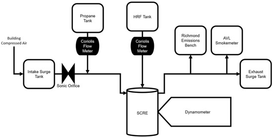
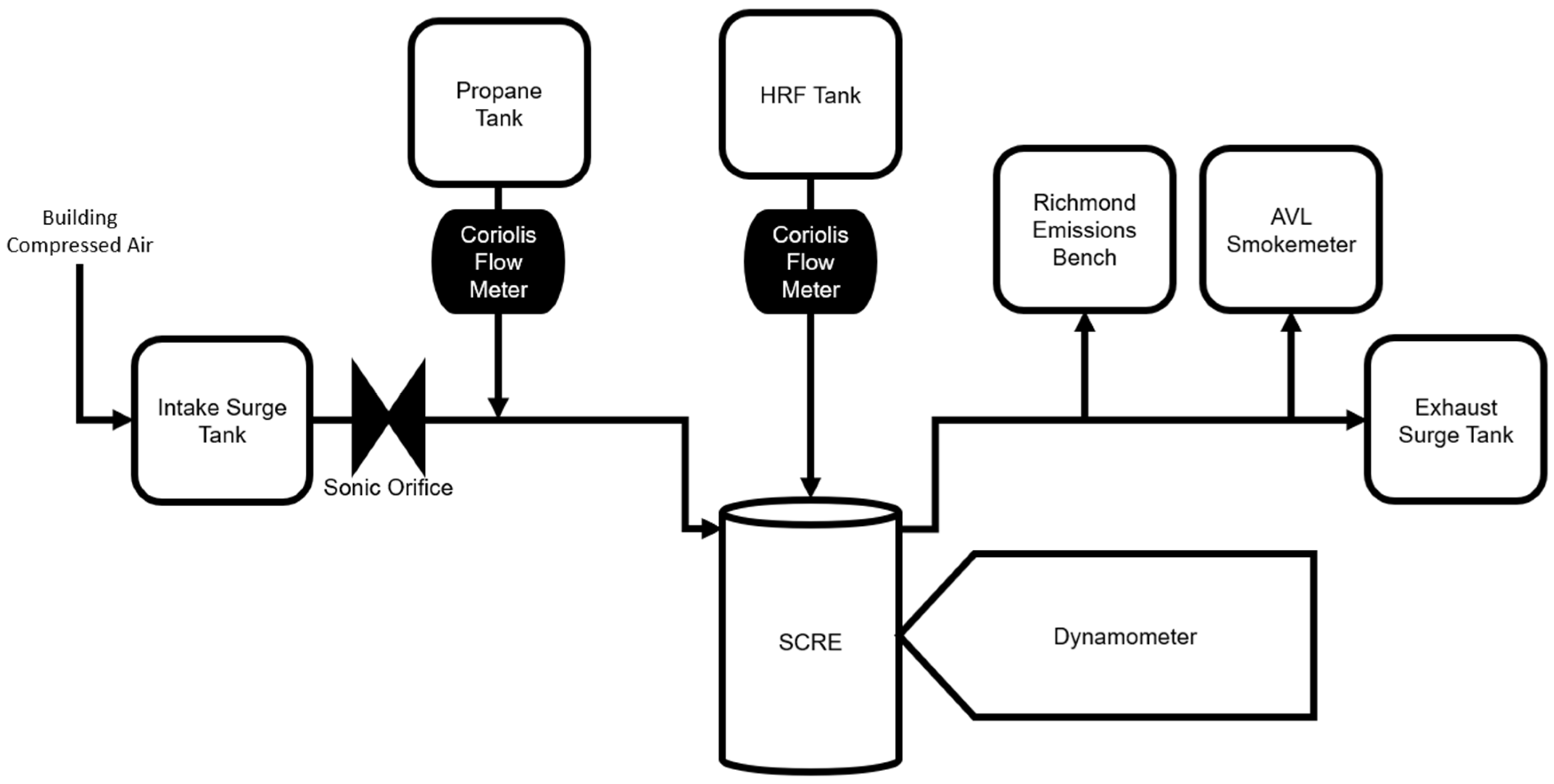
All experiments were performed on the heavy-duty SCRE in the Engines and Combustion Laboratory at the University of Alabama. This SCRE is based on a PACCAR MX-11 production heavy-duty engine with specifications provided in Table 1. Figure 1 provides a brief representation of the experimental set-up for reference.
Table 1.
Engine specifications.
Figure 1.
SCRE test cell schematic.
The SCRE was coupled with a 393 HP AC dynamometer to maintain engine speed using a PowerTest/Dyne Systems (Sussex, WI, USA) Inter-Loc V controller. In-cylinder pressure was measured using a Kistler (Amherst, NY, USA) piezoelectric cylinder pressure sensor (Model 6124A) in conjunction with a Kistler charge amplifier (Model 5018). To synchronize engine CAD phasing to high-speed pressure data, a BEI shaft encoder with a 0.1 CAD resolution was used. Custom intake, exhaust, coolant, oil, lubricant conditioning, and fuel systems were used to meet engine requirements.
The intake air system can supply pressurized intake air up to 5 bar pressure using an external air compressor and a heatless desiccant dryer. The engine’s intake and exhaust system include separate surge tanks equipped to help mitigate flow oscillations in the manifolds. Both the tanks were equipped with over-pressure valves, and the intake tank also had an anti-crunch valve for safe operation under naturally aspirated conditions. A FlowMaxx sonic nozzle (Model SN16-SA-354, Emerson Coriolis, North Richland Hills, TX, USA), which was held under choked conditions for all engine operating points, was used to measure the intake air flow rate. Two water-cooled Kistler dynamic piezoresistive pressure transducers (Model 4624A), coupled with amplifiers (Model 4049A), were used to measure dynamic intake and exhaust manifold pressures.
Fueling was handled through two separate subsystems. The HRF system contained a low-pressure loop that was connected to a Delphi high pressure fuel injection pump, which fed the HRF to the injector through a common rail. Fuel flowrates were measured by a Emerson Coriolis mass flow meter (Model CMFS010M319N0A2ECZZ, St. Louis, MO, USA) in the low-pressure system as it supplied fuel to a level tank. The level tank was used to mitigate any pressure/flow variations as well as to remove any air from the system before it entered the Delphi fuel injection pump. The LRF system supplied propane from standard 40 lb bottles to the engine intake by means of an electronic needle valve (Rotork/Hanbay Model MCM-050AB, Houston, TX, USA) and a Swagelok pressure regulator to control LRF supply pressure. The LRF flowrates were measured using the same model of Emerson Coriolis mass flow meter as for the HRF. The fuel properties of both POMDME (OME1 = 0.02%; OME2 = 0.12%; OME3 = 47.76%; OME4 = 29.58%; OME5 = 16.38%; OME6 = 5.37%) and diesel are given in Table 2 [23,25,26].
Table 2.
High reactivity fuel properties.
The coolant system (50/50 ethylene glycol–water mix) used a dedicated heat exchanger and building process water to cool the engine coolant. The lubrication system provided 15W-40 oil to the SCRE and the Delphi high-pressure pump by means of a gear pump. Lubricant oil cooling was handled by a second coolant system (also a 50/50 ethylene glycol–water mix), which was also used to cool the piezoresistive pressure transducers.
All static pressures were measured using DwyerOmega (Michigan City, IN, USA) pressure transducers (Model PX119 series), while a higher accuracy Setra (Boxborough, MA, USA) pressure transducer (Model 206) measured pressures in the intake and the exhaust. Omega Type-K thermocouples measured all temperatures on the SCRE setup. Engine-out emissions (CO, CO2, O2 NOx, and HC) were measured with a Richmond Instruments and Systems five-gas emissions bench. As a reference, uncertainties for all measurement devices are provided in Table 3.
Table 3.
Experimental instrumentation uncertainties.
High-speed data acquisition was handled through a National Instruments (Austin, TX, USA) PXI 6356 device, coupled with a NI cDAQ system, which handled slow-speed data and a National Instruments Direct Injector Control and Measurements device (DCM 2316) and in-house LabView system allowed monitoring and control of engine operating conditions. The Vieletech combustion analysis toolkit software was used for online combustion analysis during engine operation.
Coolant and oil temperatures were maintained using a PID controller at 45 °C and 75 °C, respectively. One thousand consecutive cycles of in-cylinder pressure data were taken at each operating condition, along with corresponding static pressures, temperatures, and emissions. All these data were postprocessed using an in-house MATLAB R2024a R2023 code to determine the apparent heat release rate (AHRR) along with other combustion and performance parameters. The code uses the Redlich–Kwong real-gas equation of state to determine the in-cylinder temperatures, and chemical equilibrium and NASA polynomial-based specific heats [27] to determine specific heat ratio (), which is then used in the first law of thermodynamics energy equation to determine the AHRR.
The MATLAB post-processing code used the following equations to characterize in-cylinder engine combustion.
In the above equations, refers to the mass flow rates measured in kilograms per hour. LHV refers to the lower heating value of the given fuel, which for the HRFs is given in Table 2. The equivalence ratio () uses the stoichiometric air fuel ratio which is the ratio of fuel (both HRF and LRF) to air required to completely convert the fuel input into end products of combustion (CO2 and H2O). Combustion efficiency () is calculated by first calculating combustion inefficiency based on specific exhaust species (CO, HC, etc.) and their respective lower heating values. The LHVs for CO, and H2 are assumed to be 10.1 MJ/kg, and 120 MJ/kg respectively; the LHV of HC is assumed to be the same as the mixture of HRF and LRF as recommended by Heywood [25].
4. Testing Procedure
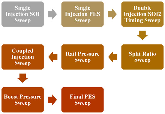
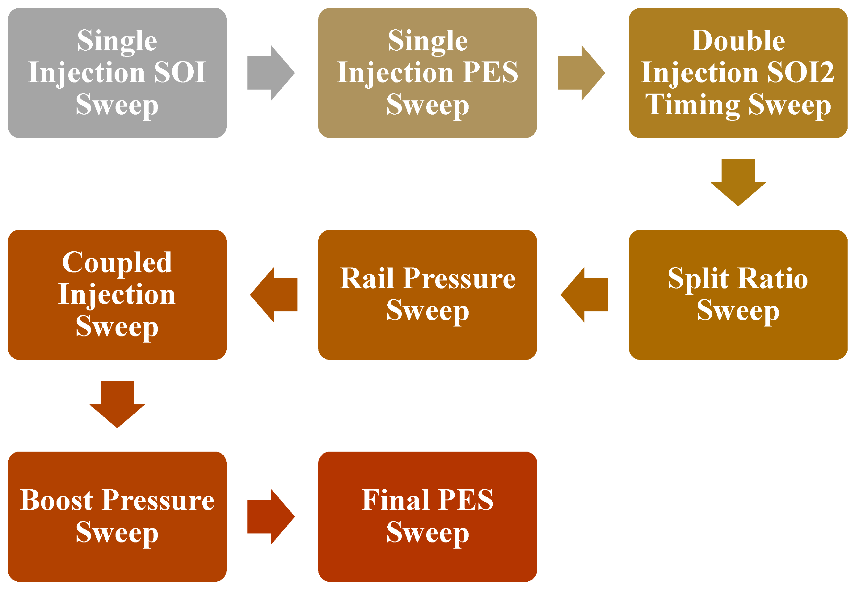
Diesel–propane and POMDME–propane dual fuel combustion were studied at 5 bar IMEPg and 1339 rpm with a specific focus on improving emissions, efficiency, and performance. Figure 2 gives a detailed process flowchart for testing strategies. Global limits of <1 g/kWh of engine-out NOx emissions, <15 bar/CAD of maximum pressure rise rate (MPRR), and a coefficient of variation (COV) of IMEPg < 5% were set to ensure optimal performance–emissions tradeoffs during the experimental campaign.
Figure 2.
Process flowchart showing the dual fuel testing methodology adopted in this work.
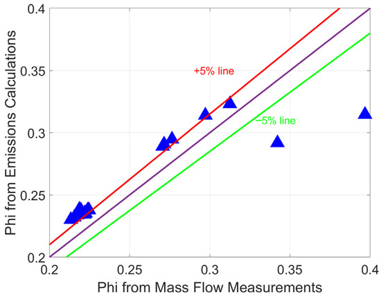
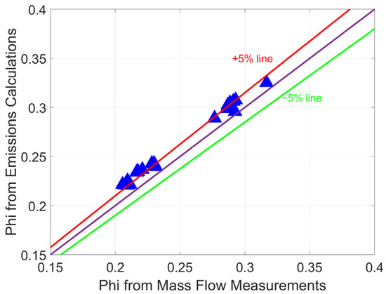
Several steps were taken to ensure the consistency of engine operation across different days and to gain confidence in the test data, including but not limited to: (1) cold motoring tests, (2) hot motoring tests (after firing data acquisition was completed), (3) “daily baseline firing tests” at fixed operating conditions for neat diesel and dual fuel combustion, and (4) post-operational checks for operational consistency using “phi vs. phi” plots. The interested reader is referred to Pearson [28] for the first three sets of data consistency results; they are not presented here for the sake of brevity. As an example of data consistency, phi vs. phi plots are discussed here. Emissions data were checked for consistency by comparing the equivalence ratio based upon measured fuel and air flow rates against the equivalence ratio calculated using measured emissions data. Sample phi vs. phi plots for diesel–propane and POMDME–propane dual fuel combustion at a typical operating condition are presented in Figure 3 and Figure 4, respectively. Perfect correlation between the equivalence ratios based on emissions and mass flow rates is shown as a 45-degree line, along with “±5% disagreement lines.” It is evident that most of the data points fall within the ±5% disagreement lines, indicating internally consistent and overall reliable experimental data.
Figure 3.
Phi vs. phi comparison plot for diesel–propane dual fuel combustion.
Figure 4.
Phi vs. phi comparison plot for POMDME–propane dual fuel combustion.
5. Results and Discussion
The results for diesel–propane and POMDME–propane fueling combinations are presented and compared in the following section in the sequence of the testing procedure previously discussed in Figure 2. One exception is that detailed results for the injection ratio study are not presented here because that parameter had a negligible impact on efficiencies and emissions.
5.1. SOI Sweep
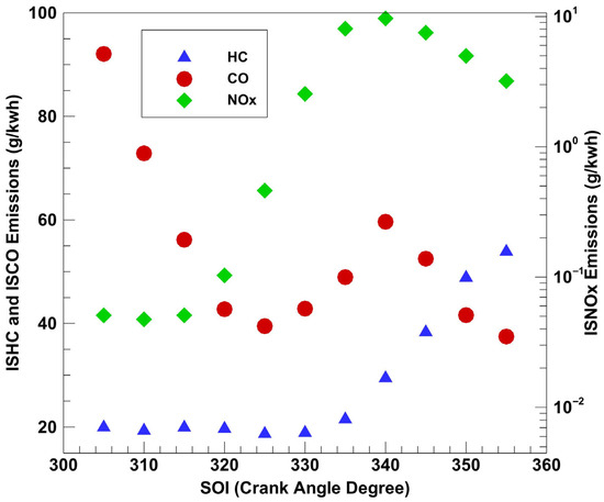
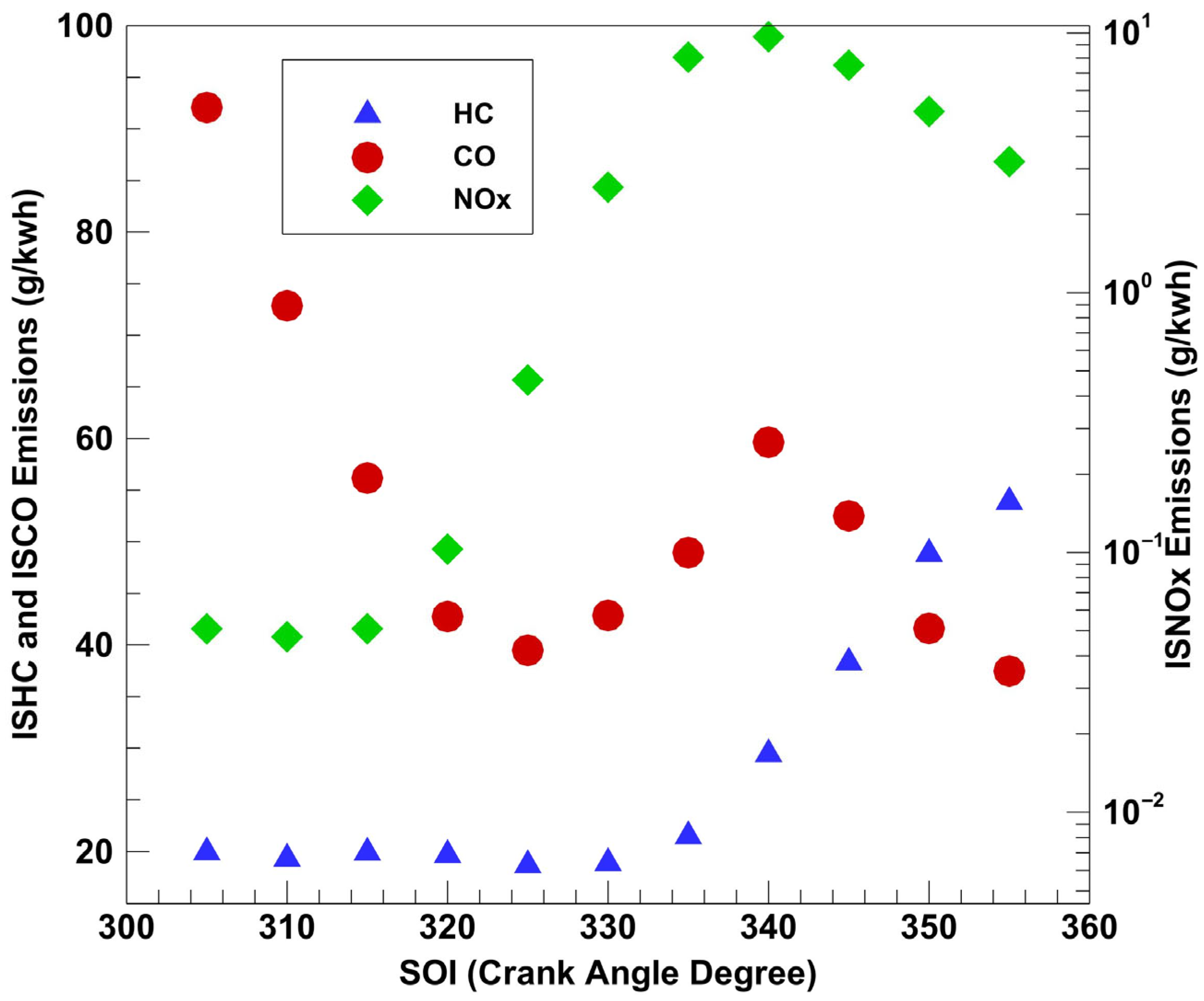
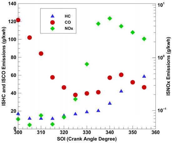
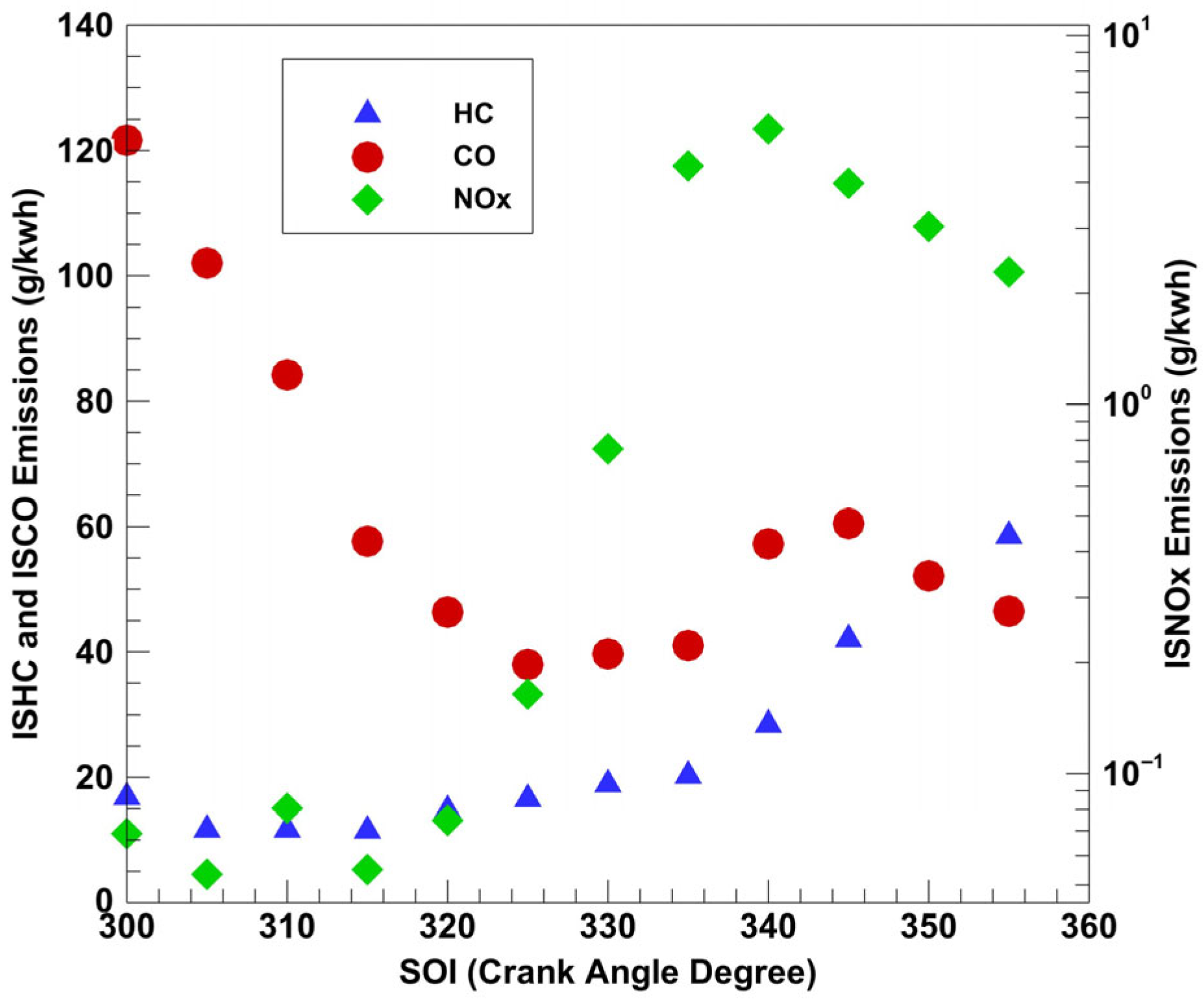
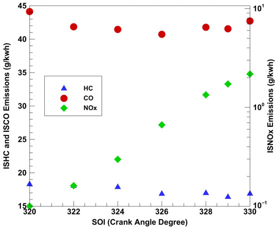
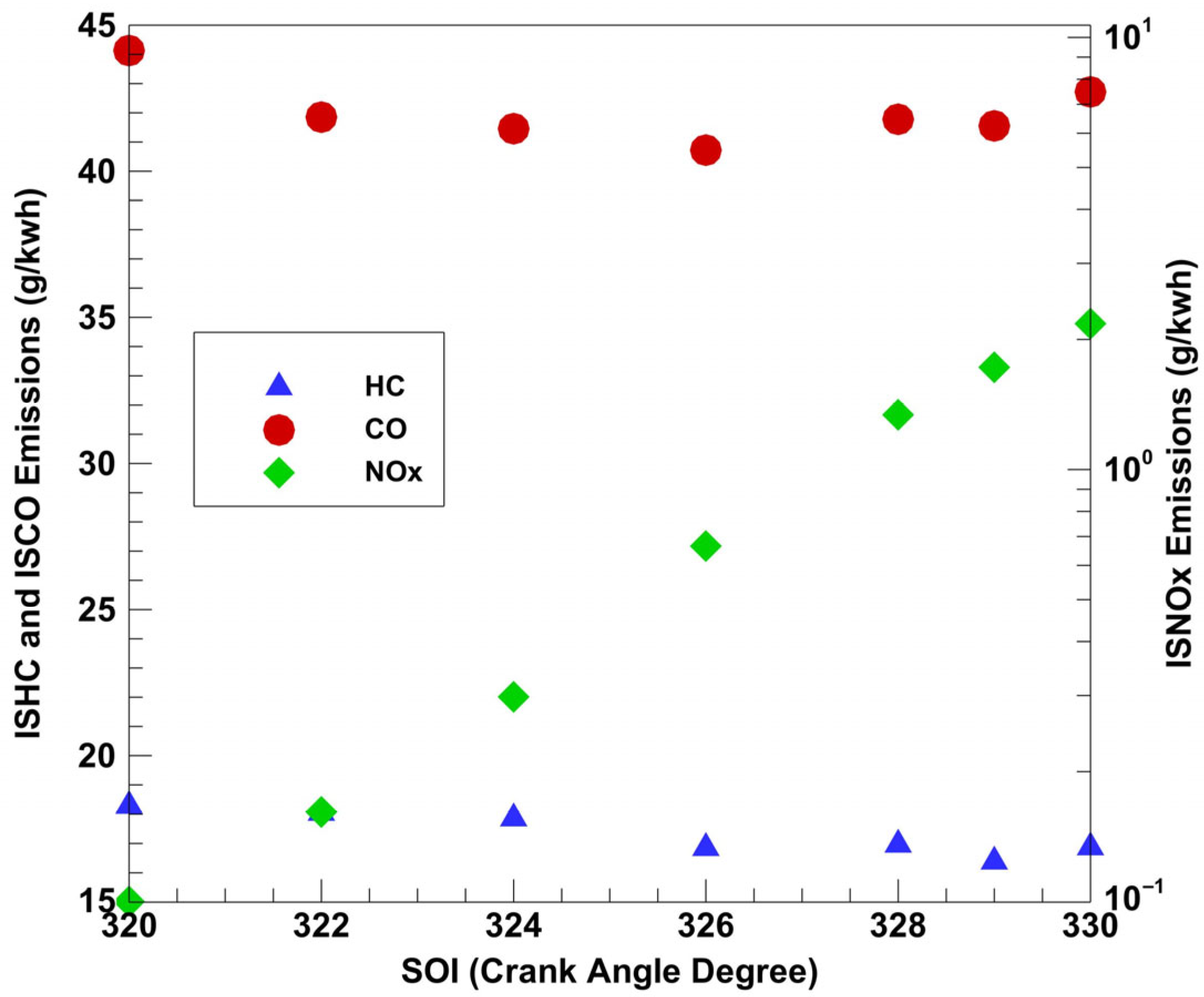
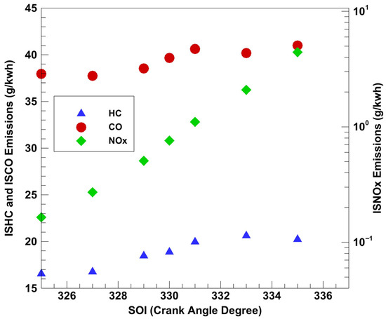
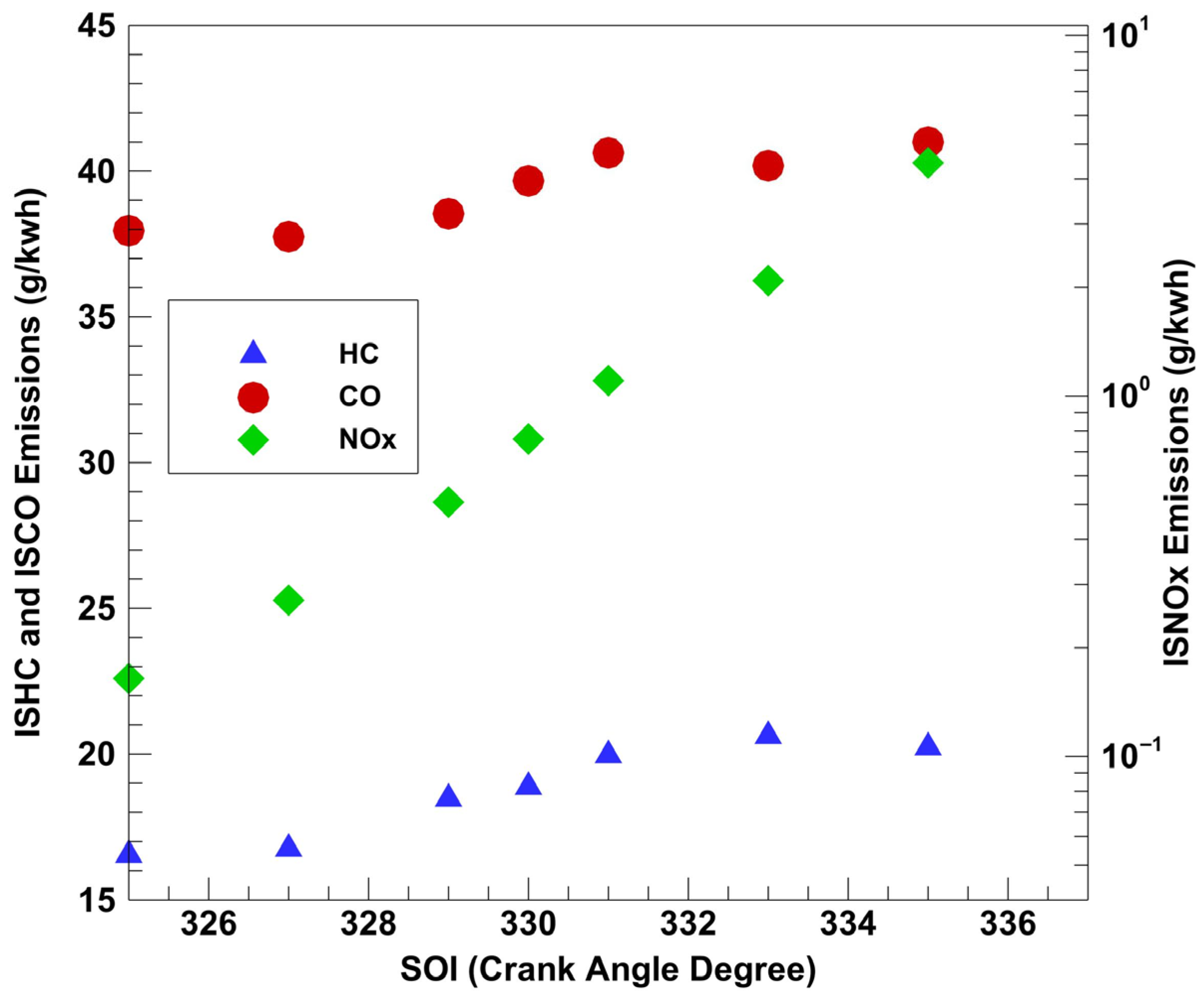
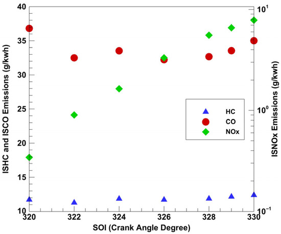
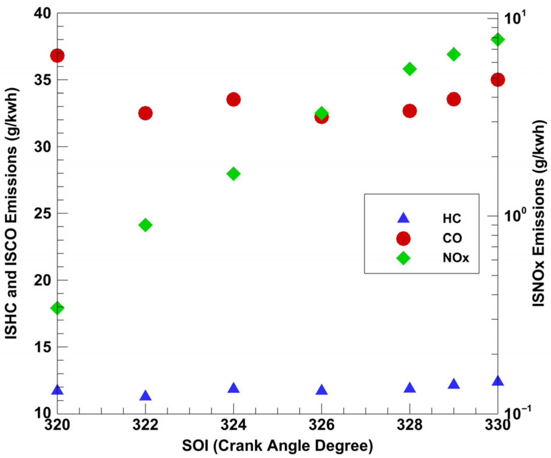
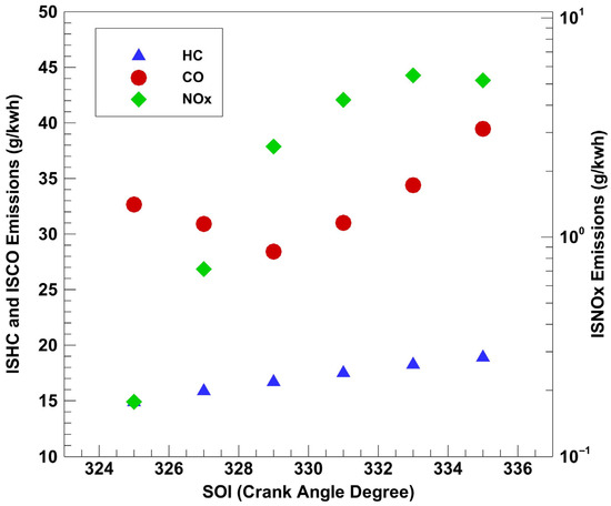
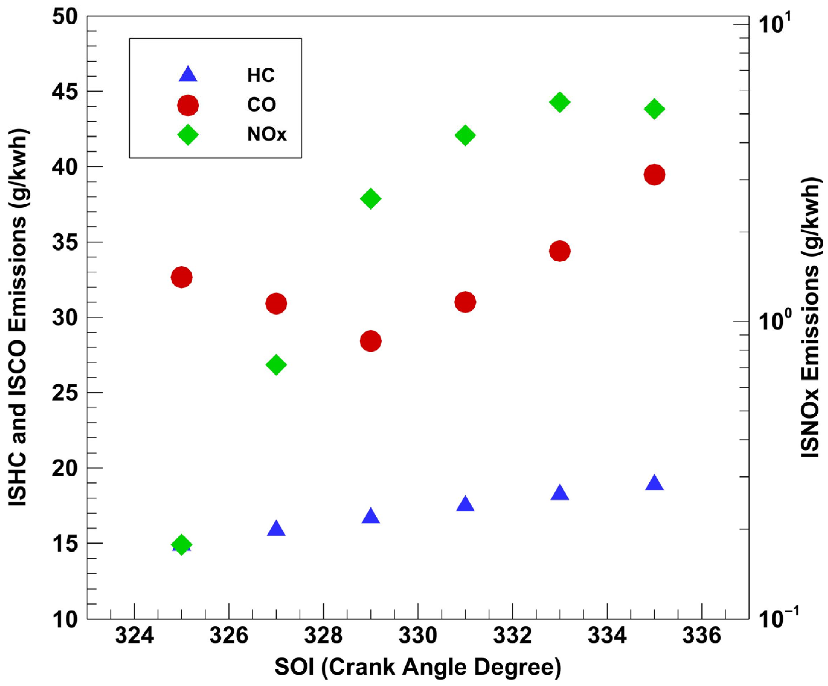
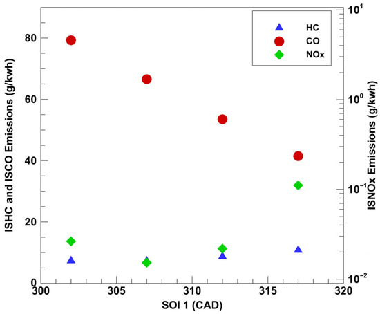
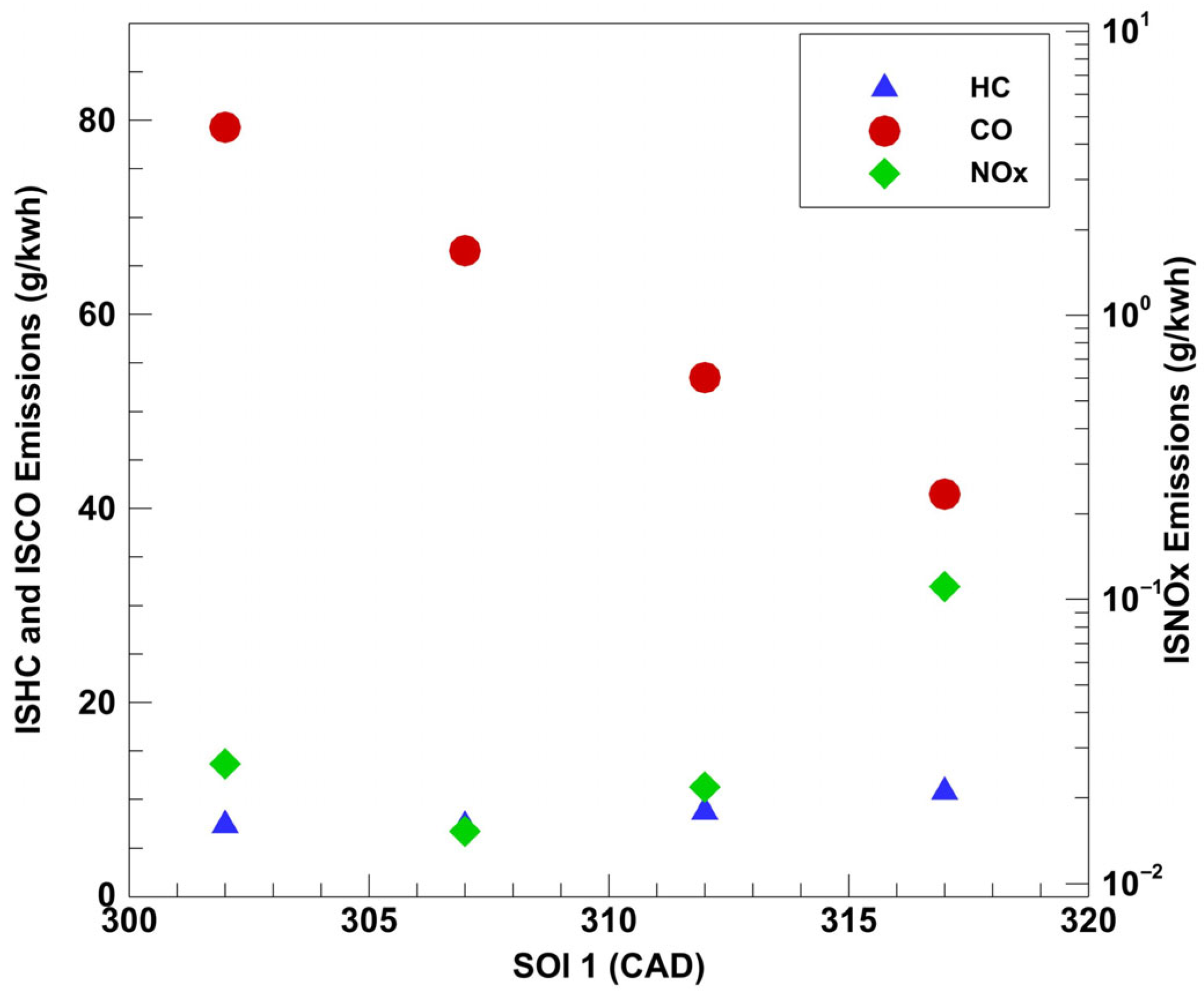
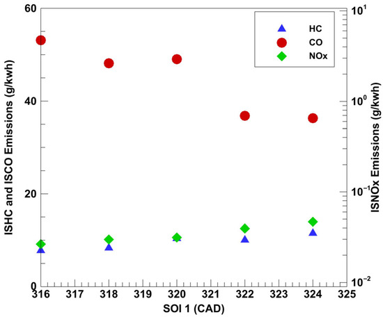
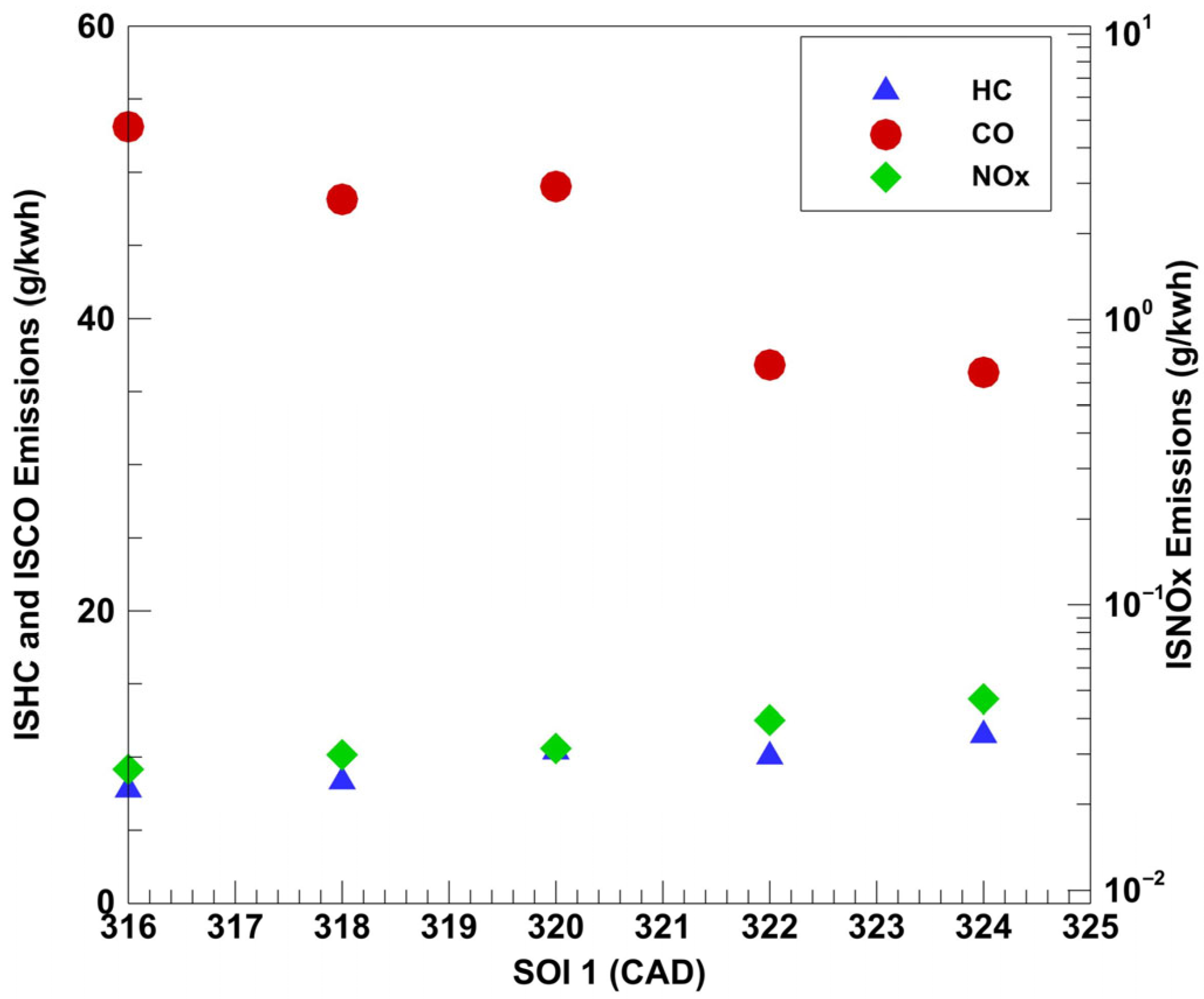
A commanded SOI sweep was first performed in 5-degree increments. Commanded injection durations and the LRF flow rates were continuously adjusted to maintain load and PES at 5 bar IMEPg and 80%, respectively. Emissions data for diesel–propane and POMDME–propane combustion are presented in Figure 5 and Figure 6, respectively. The ISHC and ISCO emissions are presented on the left y-axis, while indicated specific oxides of nitrogen (ISNOx) emissions are presented on the right y-axis on a log scale.
Figure 5.
Single injection SOI sweep emissions data (diesel–propane) at 1339 rpm, 5 bar IMEPg, and 80 PES.
Figure 6.
Single injection SOI sweep emissions data (POMDME–propane) at 1339 rpm, 5 bar IMEPg, and 80 PES.
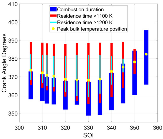
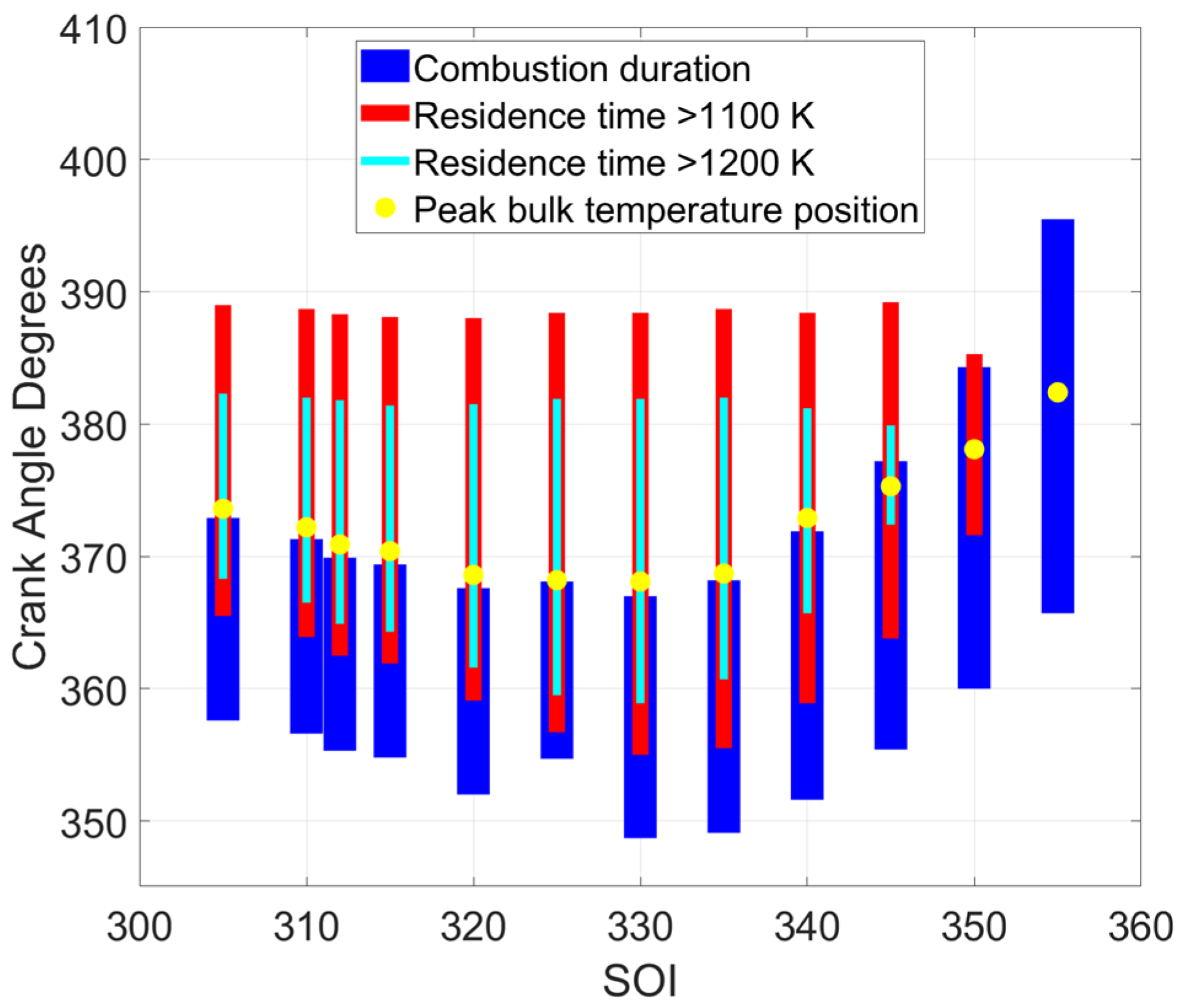
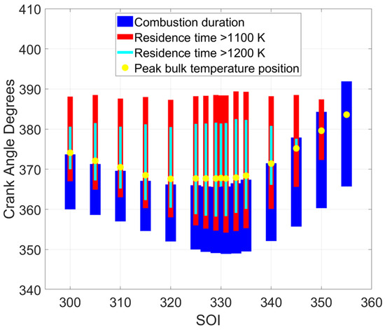
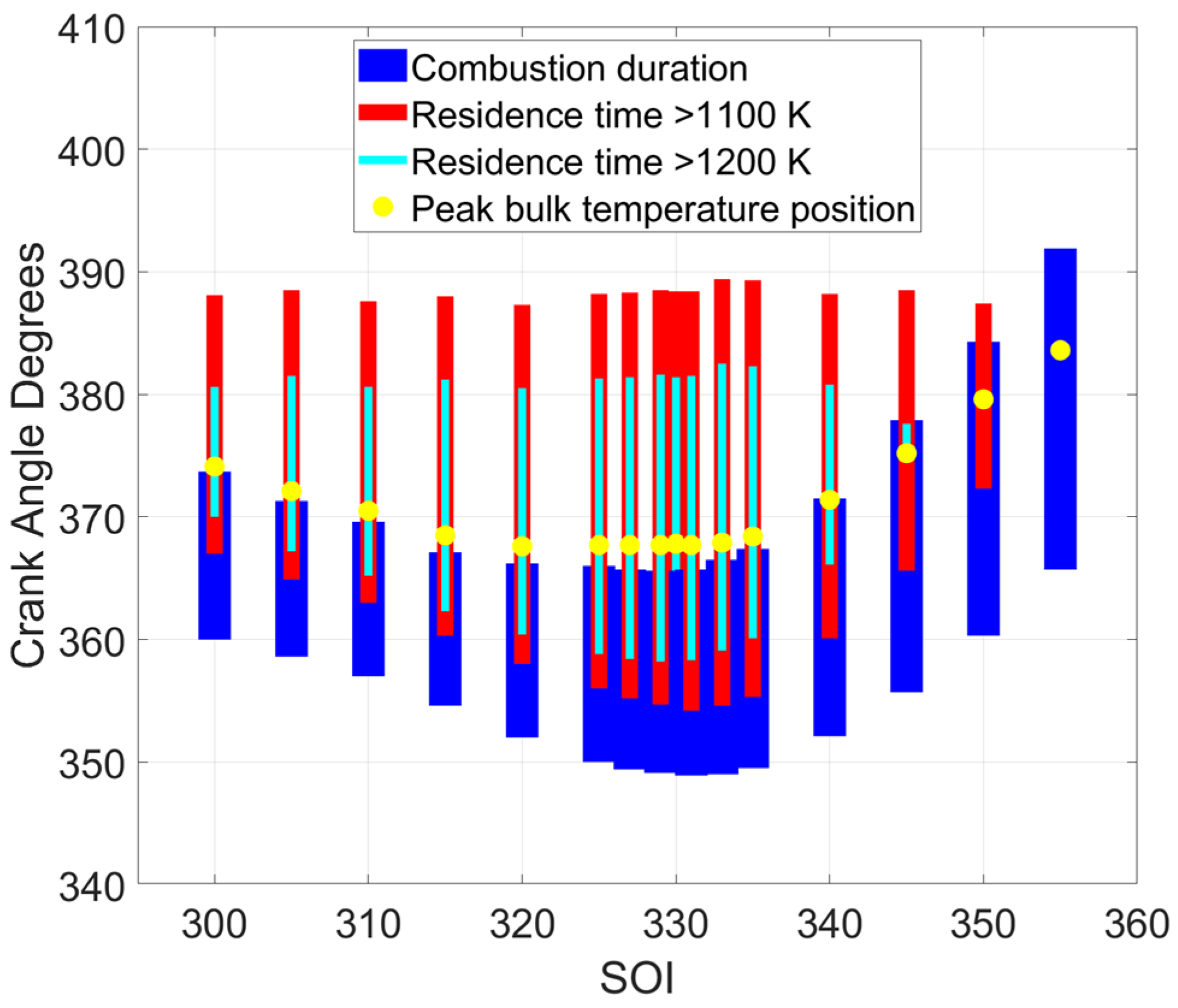
Both fueling combinations showed ISNOx reductions when advancing SOI before 340 CAD. This is due to the greater time available for in-cylinder mixing with an earlier HRF injection leading to more homogeneous combustion with lower local temperatures. Both fuels exhibit an increase in CO emissions for SOI earlier than 325 CAD, a trend attributable to there being less time spent at high temperature conditions that facilitate CO oxidation. This is supported by Figure 7 and Figure 8, which show “high temperature residence times” at different SOIs. These residence times are calculated as the crank angle duration for which bulk gas temperatures exceed 90% (in light blue) and 80% (in red) of the peak bulk gas temperature. As peak bulk gas temperatures for dual fuel combustion at early SOIs and high PES typically do not exceed 1500 K, which is the accepted minimum threshold temperature for CO oxidation [29], this approach for determining residence times was created to correlate CO emissions with bulk gas temperatures. For SOIs earlier than 325 CAD, the higher temperature residence times are shorter, corresponding to higher measured CO emissions. It is also interesting to note that the combustion duration and the high temperature residence times are not always directly correlated. For example, in Figure 7, while combustion duration is ~25 CAD for 350 CAD SOI, the high temperature (>1100 K) residence time is only ~12 CAD; however, for 305 CAD SOI, while combustion duration is only ~14 CAD, the high temperature (>1100 K) residence time is ~25 CAD.
Figure 7.
Single injection SOI sweep residence time plots (diesel–propane) at 1339 rpm, 5 bar IMEPg, and 80 PES.
Figure 8.
Single injection SOI sweep residence time plots (POMDME–propane) at 1339 rpm, 5 bar IMEPg, and 80 PES.
5.2. AHRR Transformation Region
In dual fuel combustion, when SOI is varied over a wide range, the AHRR profile is transformed from a traditional two-stage AHRR at relatively late SOIs to a single-stage “Gaussian” AHRR at earlier SOIs. As SOI is advanced, this AHRR transformation is usually accompanied by a steep decrease in engine-out NOx emissions. Therefore, it is very important to ensure that the AHRR is indeed transformed to a single-stage Gaussian profile to reduce NOx emissions. In this section, AHRR transformation is presented for two different PES values, 80 PES and 70 PES, to mirror the SOI sweep.
5.2.1. Percent Energy Substitution (PES): 80 PES
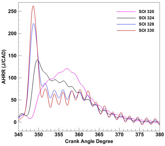
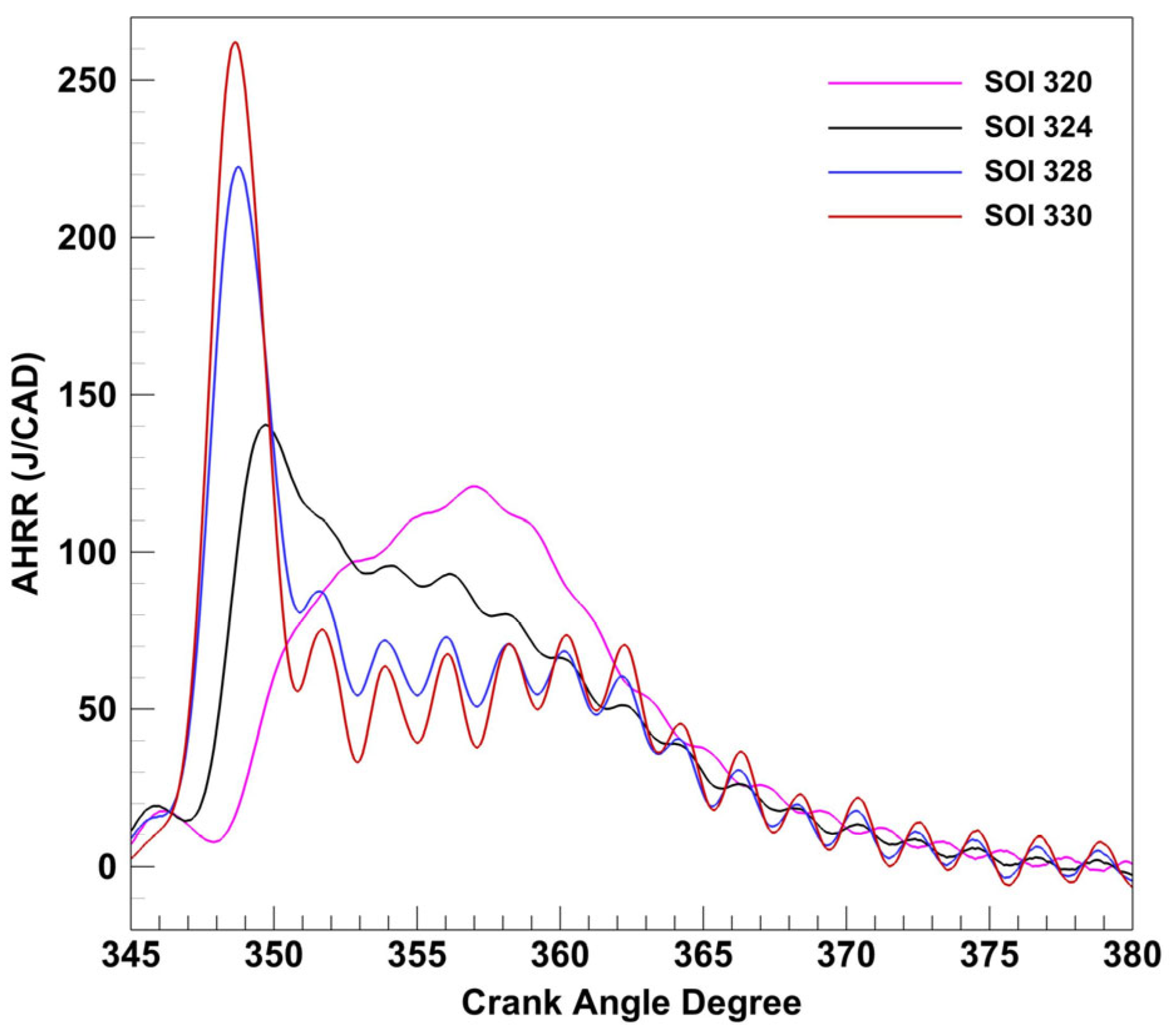
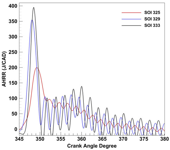
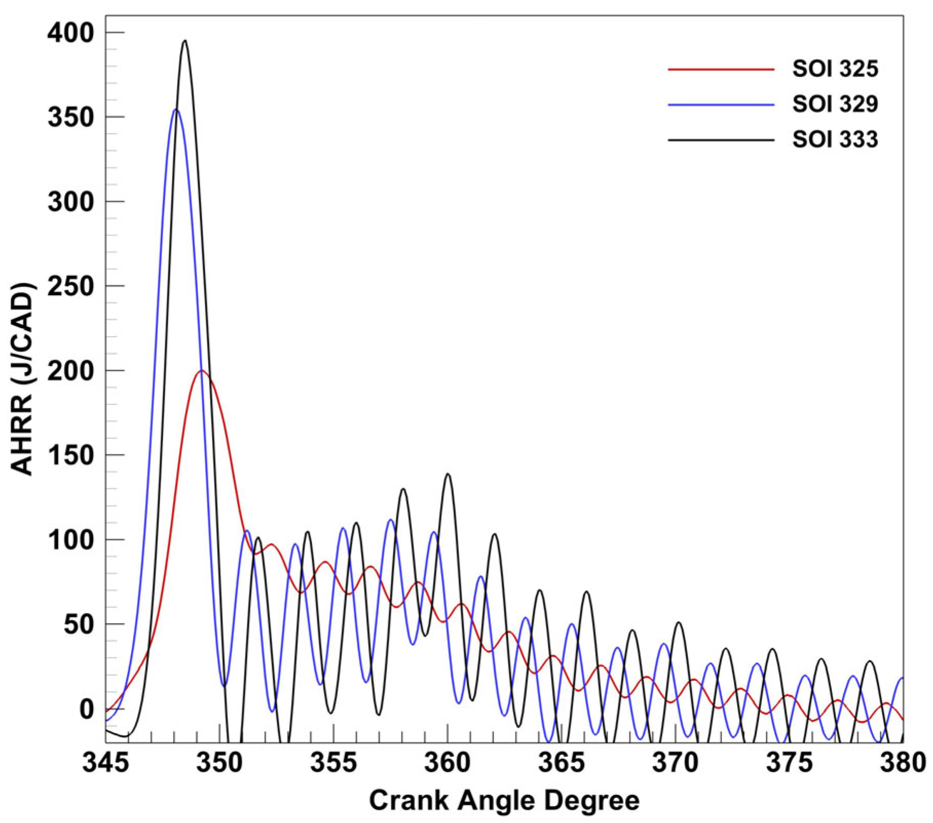
The AHRR profiles at 80 PES are shown in Figure 9 and Figure 10. During the AHRR transformation, as SOI is advanced the HRF has more time between the end of injection and the start of combustion for in-cylinder mixing, which leads to more homogeneous, low-temperature combustion. This expectation is corroborated by emissions data shown in Figure 11 and Figure 12, where NOx emissions decrease exponentially as SOI is advanced. It is apparent that POMDME–propane combustion exhibits a higher first stage AHRR peak compared to diesel–propane combustion. This is likely due to the higher cetane number/reactivity of POMDME. An additional contributor to this trend could be its lower LHV, which requires a greater mass of POMDME to be injected into the cylinder to retain the same PES, leading to higher LTHR peaks. This hypothesis will require further testing using CFD or direct measurements.
Figure 9.
AHRR transformation (diesel–propane) at 1339 rpm, 5 bar IMEPg, and 80 PES.
Figure 10.
AHRR transformation (POMDME–propane) at 1339 rpm, 5 bar IMEPg, and 80 PES.
Figure 11.
AHRR transformation emissions (diesel–propane) at 1339 rpm, 5 bar IMEPg, and 80 PES.
Figure 12.
AHRR transformation emissions data (POMDME–propane) at 1339 rpm, 5 bar IMEPg, and 80 PES.
5.2.2. Percent Energy Substitution (PES): 70 PES
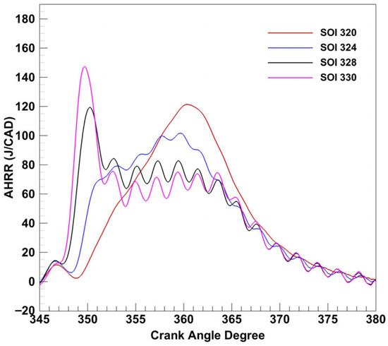
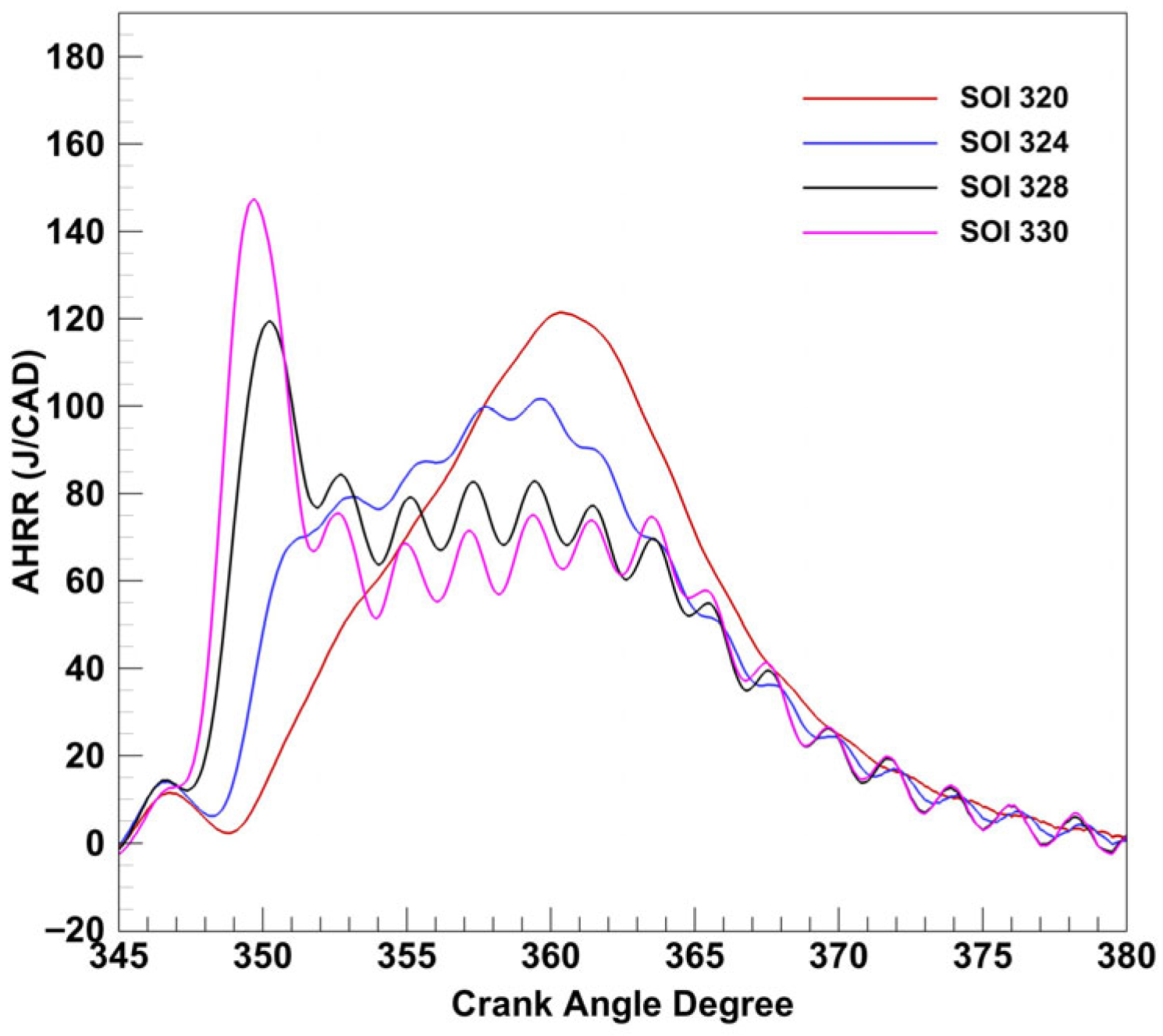
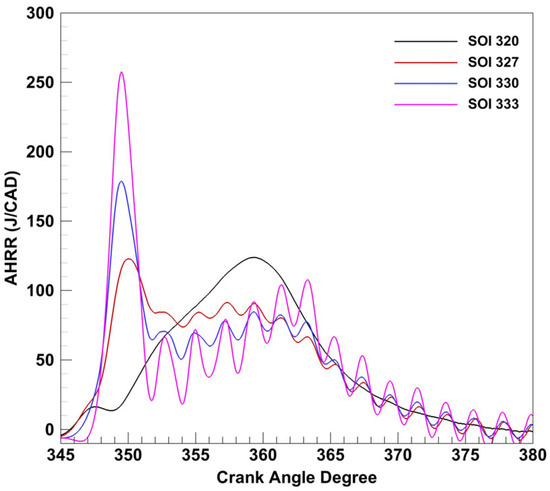
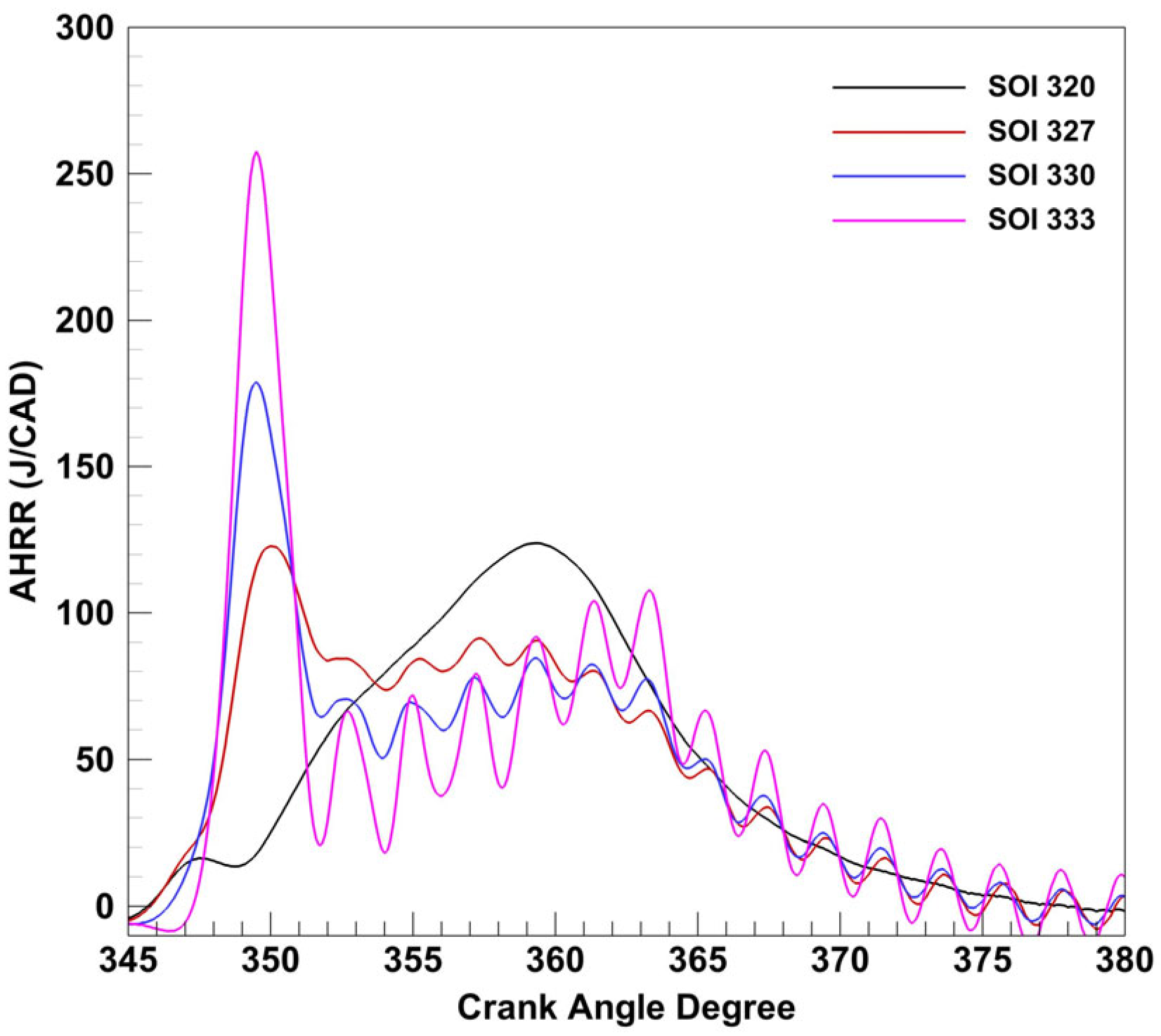
The AHRR transformation region was also examined at 70 PES, which was identified as “the best PES value” from the PES sweep (shown later). Similar trends for AHRR (Figure 13 and Figure 14) and emissions (Figure 15 and Figure 16) were observed for diesel–propane and POMDME–propane at both 70 and 80 PES; however, an important distinction is the apparent shift in the AHRR profile for POMDME-propane, which is not seen with diesel-propane. Decreasing the PES value for POMDME–propane advanced the AHRR transformation region to earlier in the cycle, where the range of SOI values at 70 PES no longer fully captures the region like it did at 80 PES. Therefore, all subsequent experiments were performed at 70 PES to effect a levelized comparison of both diesel–propane and POMDME–propane dual fuel combustion.
Figure 13.
AHRR transformation region 70 PES AHRR curves (diesel–propane) at 1339 rpm, 5 bar IMEPg, and 1.5 bar boost.
Figure 14.
AHRR transformation region 70 PES heat release rate curves (POMDME–propane) at 1339 rpm, 5 bar IMEPg, and 1.5 bar boost.
Figure 15.
AHRR transformation region 70 PES emissions data (diesel–propane) at 1339 rpm, 5 bar IMEPg, and 1.5 bar boost.
Figure 16.
AHRR transformation region 70 PES emissions data (POMDME–propane) at 1339 rpm, 5 bar IMEPg, and 1.5 bar boost.
5.3. Multiple Injections: SOI2 Sweep
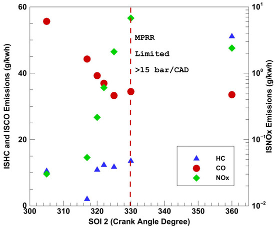
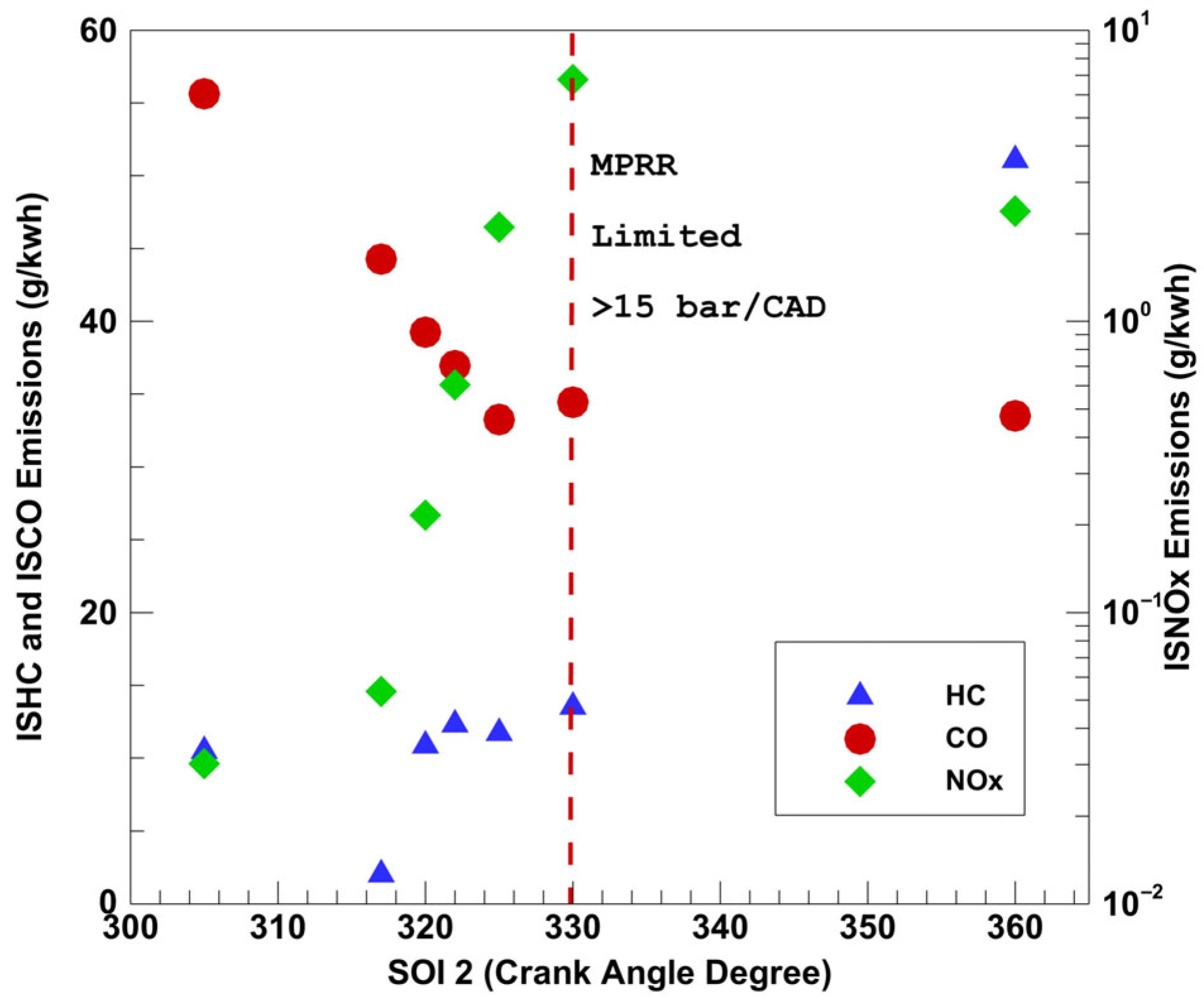
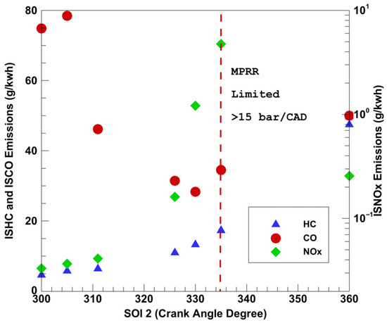
In this work, once the initial SOI1 timing was fixed, SOI2 refers to the additional injection event regardless of its timing with respect to SOI1. The SOI1 was fixed at 312 CAD for diesel and 320 CAD for POMDME, and its commanded injection duration was fixed at one-half the original value in the SOI1 sweep. The SOI2 was introduced initially closely coupled with SOI1 and then the dwell between SOI1 and SOI2 was progressively increased, while ensuring no overlap between the two injections. The commanded injection duration for SOI2 was varied at different SOI2s to achieve a constant load of 5 bar IMEPg. Previous experience with this engine [23] has shown that close coupled injections are most effective in improving emissions; therefore, greater attention was focused on close coupled injections. One “long-dwell” injection point was selected where SOI2 occurred at 360 CAD (or combustion TDC). Long-dwell injection timings have been shown in the literature to reduce the MPRR [30]; however, in this study, emissions were not improved with this approach.
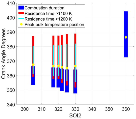
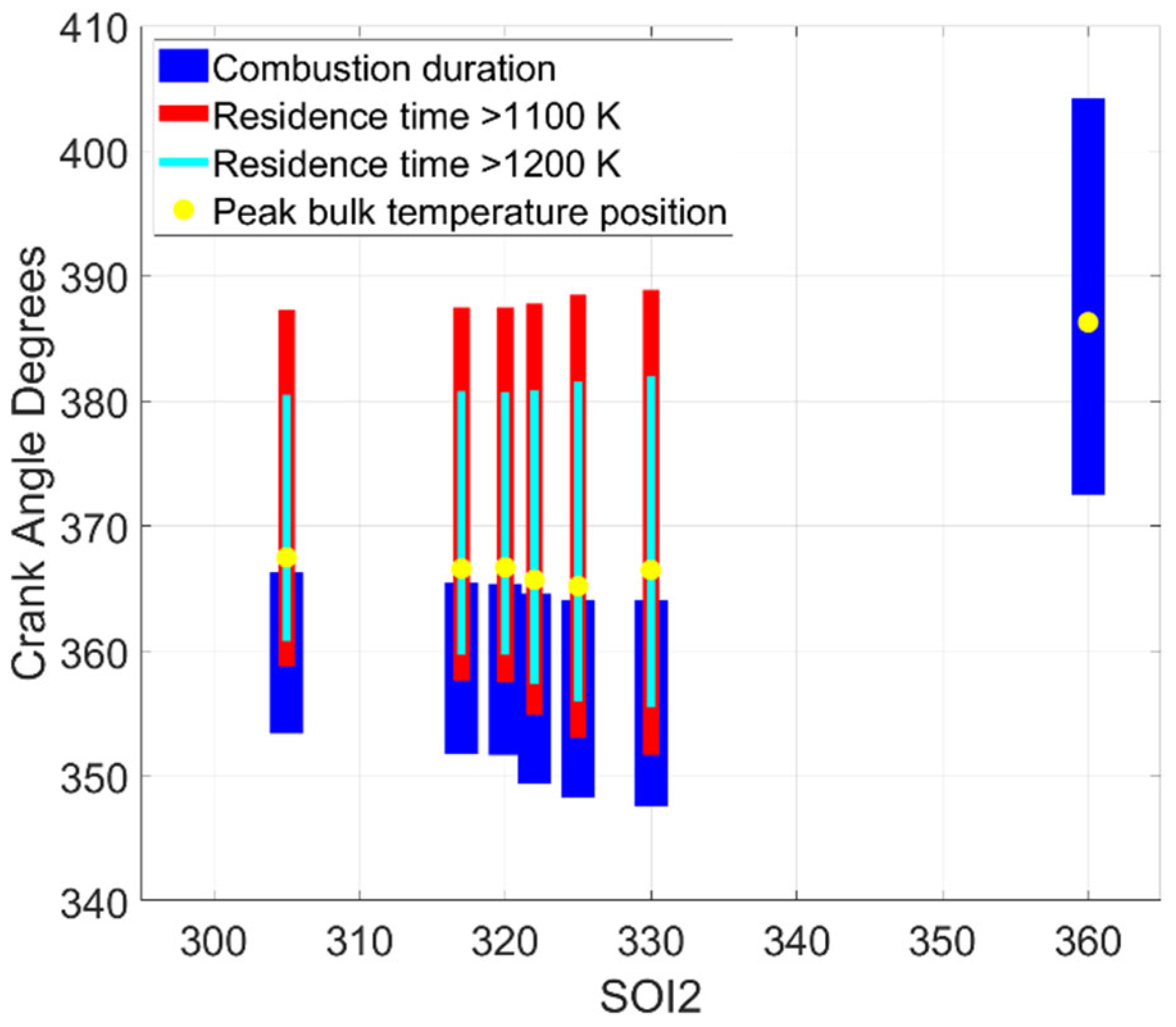
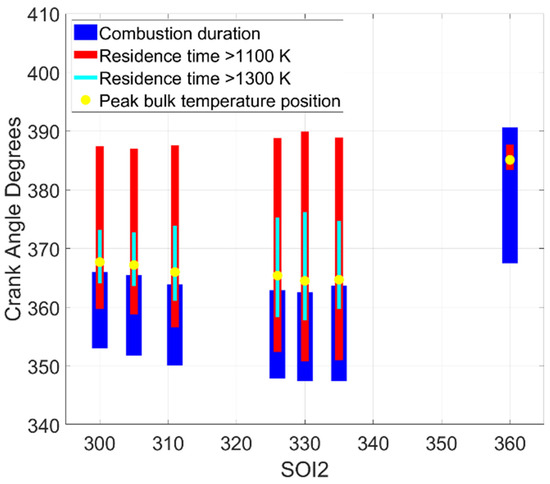
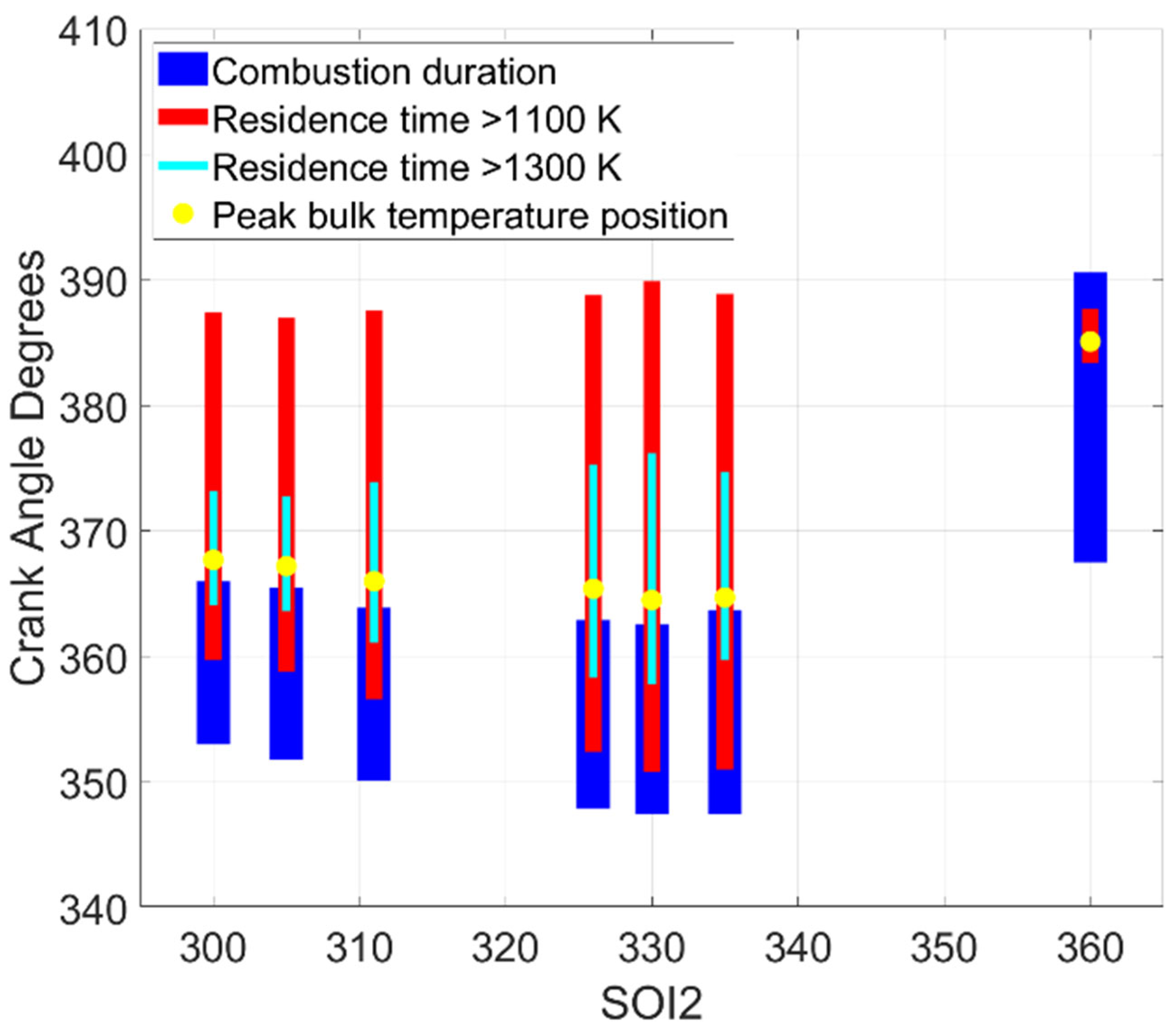
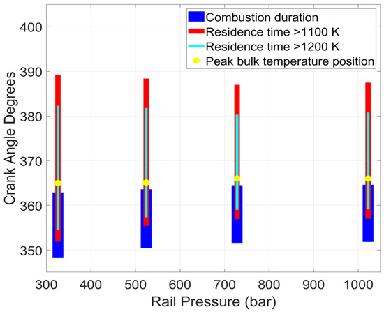
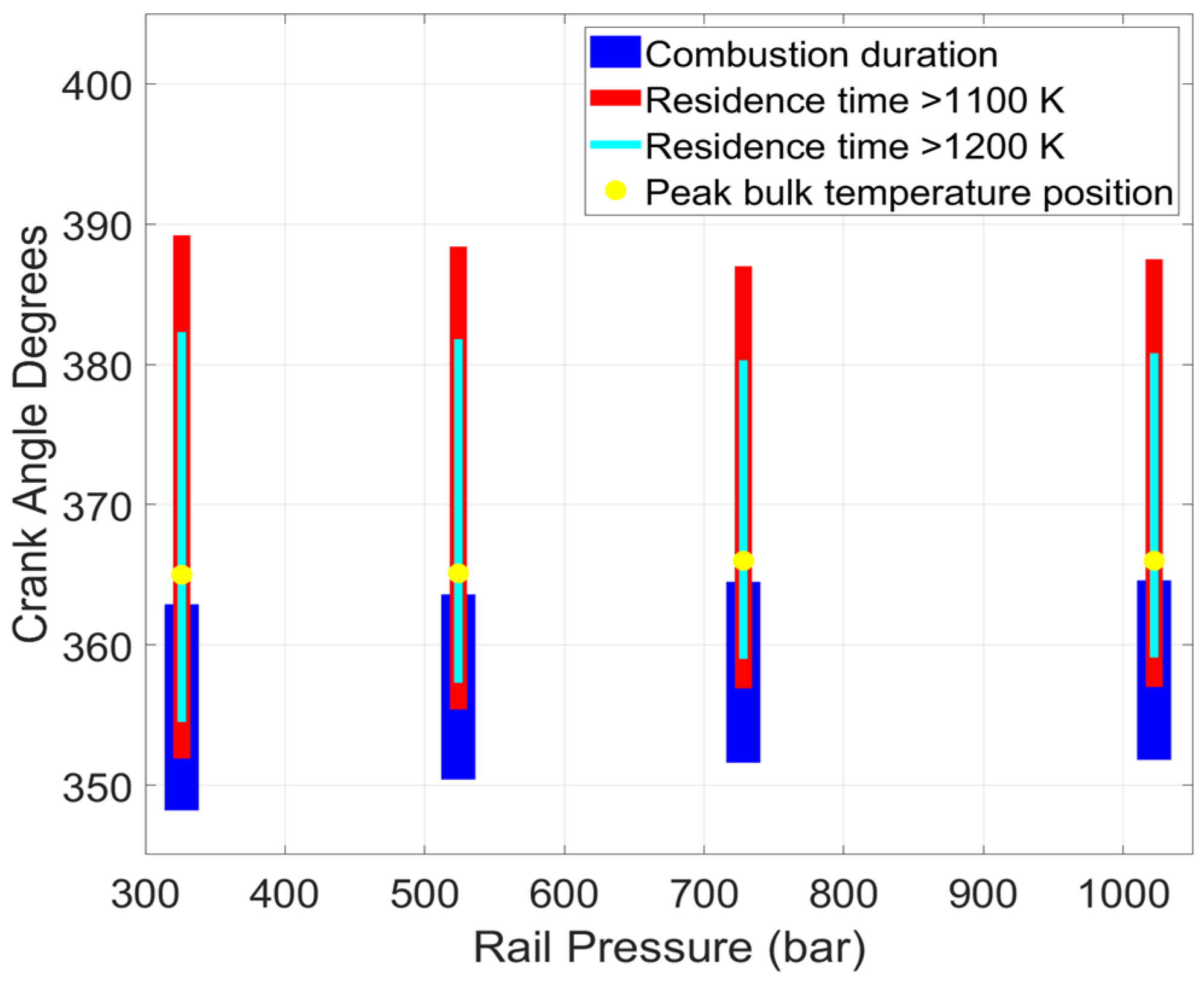
As SOI2 was advanced from 330 to 310 CAD, NOx and HC emissions decreased, as shown in Figure 17 and Figure 18. Conversely, CO emissions increased, a trend that can be explained using the residence time plots shown in Figure 19 and Figure 20. For early SOI2, shorter residence times at higher bulk gas temperatures inhibit CO oxidation to CO2.
Figure 17.
SOI2 sweep emissions data (diesel–propane) at 1339 rpm, 5 bar IMEPg, 1.5 bar boost, and 70 PES.
Figure 18.
SOI2 sweep emissions data (POMDME–propane) at 1339 rpm, 5 bar IMEPg, 1.5 bar boost, and 70 PES.
Figure 19.
SOI2 sweep residence time plots (diesel–propane) at 1339 rpm, 5 bar IMEPg, 1.5 bar boost, and 70 PES.
Figure 20.
SOI2 sweep residence time plots (POMDME–propane) at 1339 rpm, 5 bar IMEPg, 1.5 bar boost, and 70 PES.
Although Figure 19 and Figure 20 refer to bulk gas temperatures, they still indicate an average decrease in high temperature residence times at advanced SOI2s, and therefore, fewer pockets of high local temperatures. The exception to this trend is when SOI2 occurs at 360 CAD; the temperature does not exceed 1100 K for diesel–propane (or 80% of the maximum peak temperature across the entire SOI2 sweep). However, at this SOI2, the HC emissions were so high that CO emissions were low because a significant portion of the available fuel was not converted into CO.
5.4. Rail Pressure Sweep
To complete the rail pressure sweep, the SOI1 commanded injection duration was held constant while propane flowrates as well as SOI2 durations were used to maintain load and PES. An important caveat to this sweep is that stock rail pressures for the MX-11 engine could be as high as 2500 bar; therefore, at rail pressures ~300 bar and very low HRF injected quantities, the injection system operated at the extreme lower end of its design space. As fuel is used to provide cooling to the injector tip, these low flowrate conditions could also cause the injector tip to be insufficiently cooled. However, more detailed investigations are required to confirm this hypothesis.
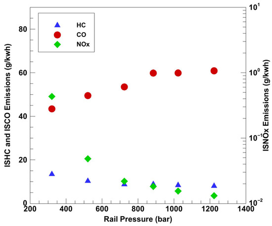
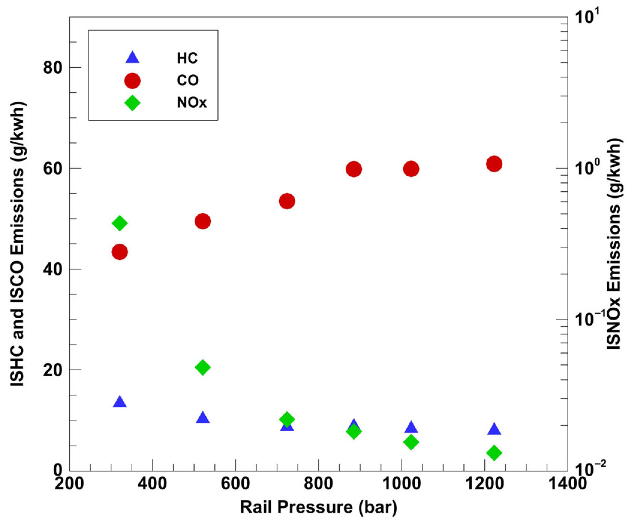
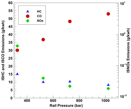
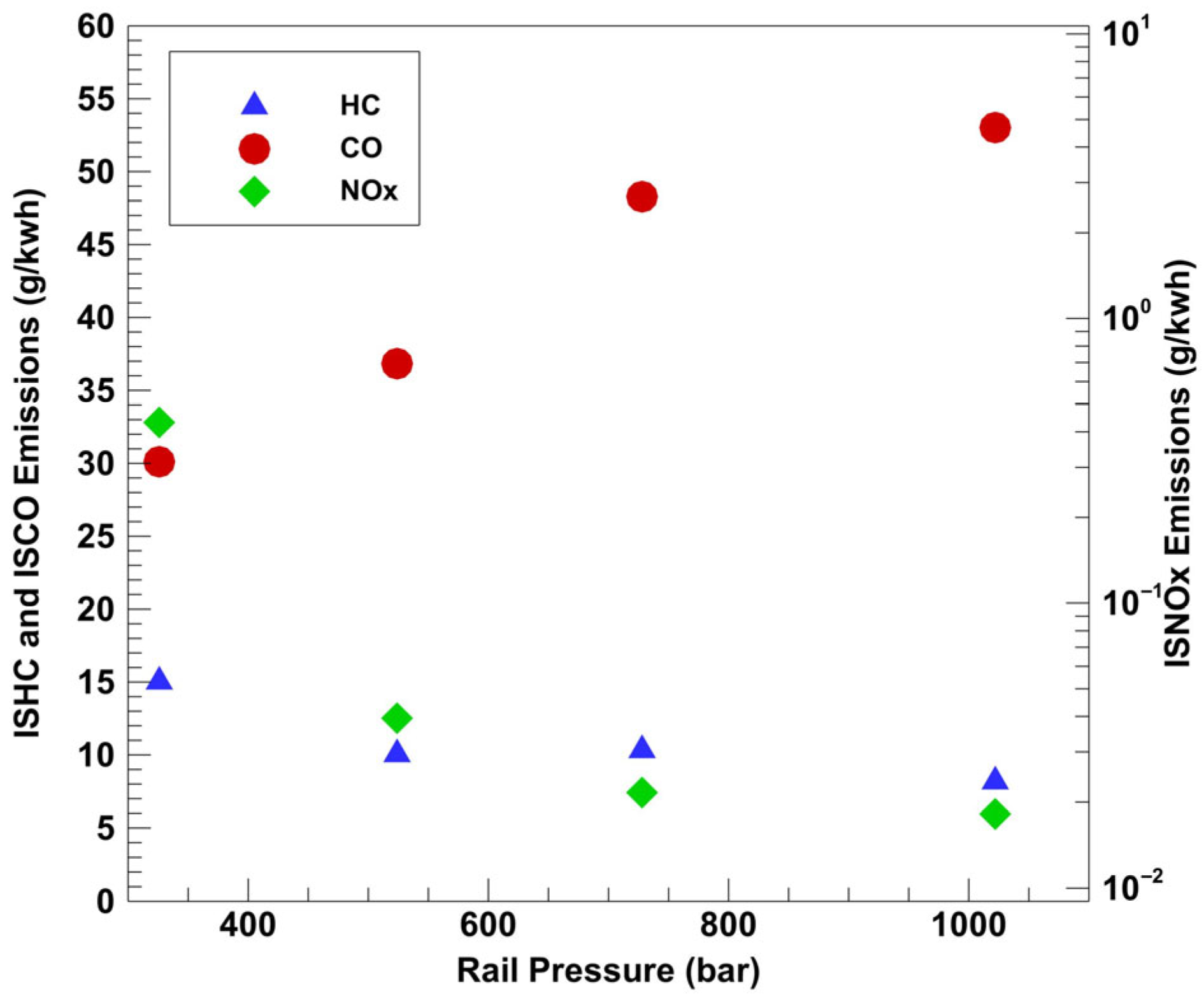
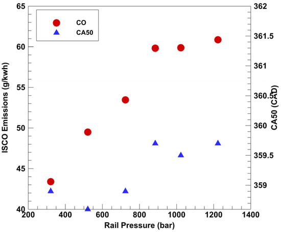
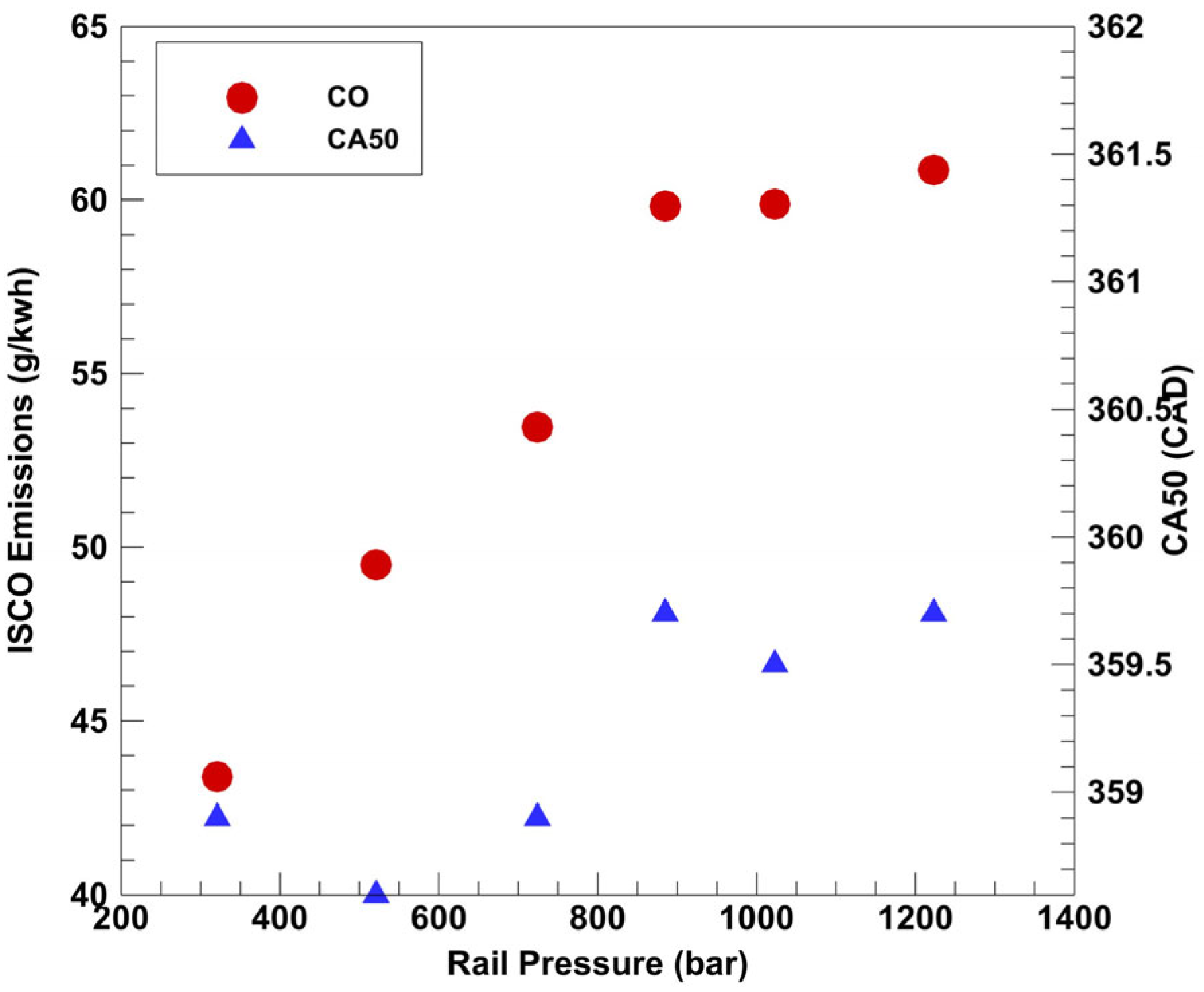
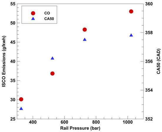
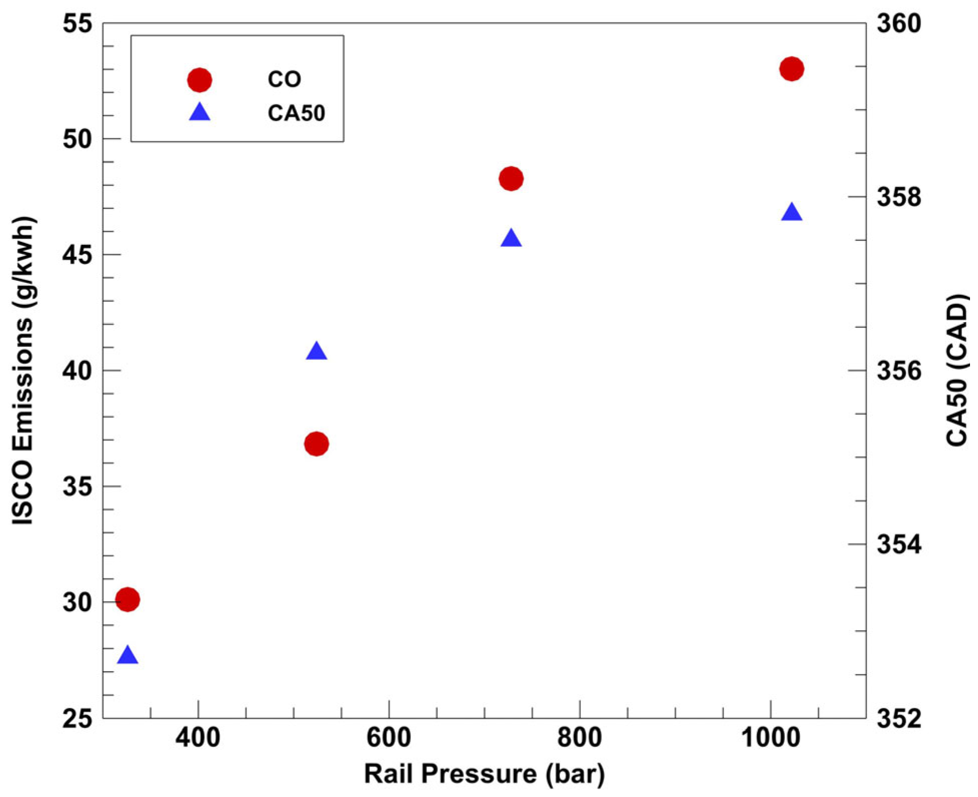
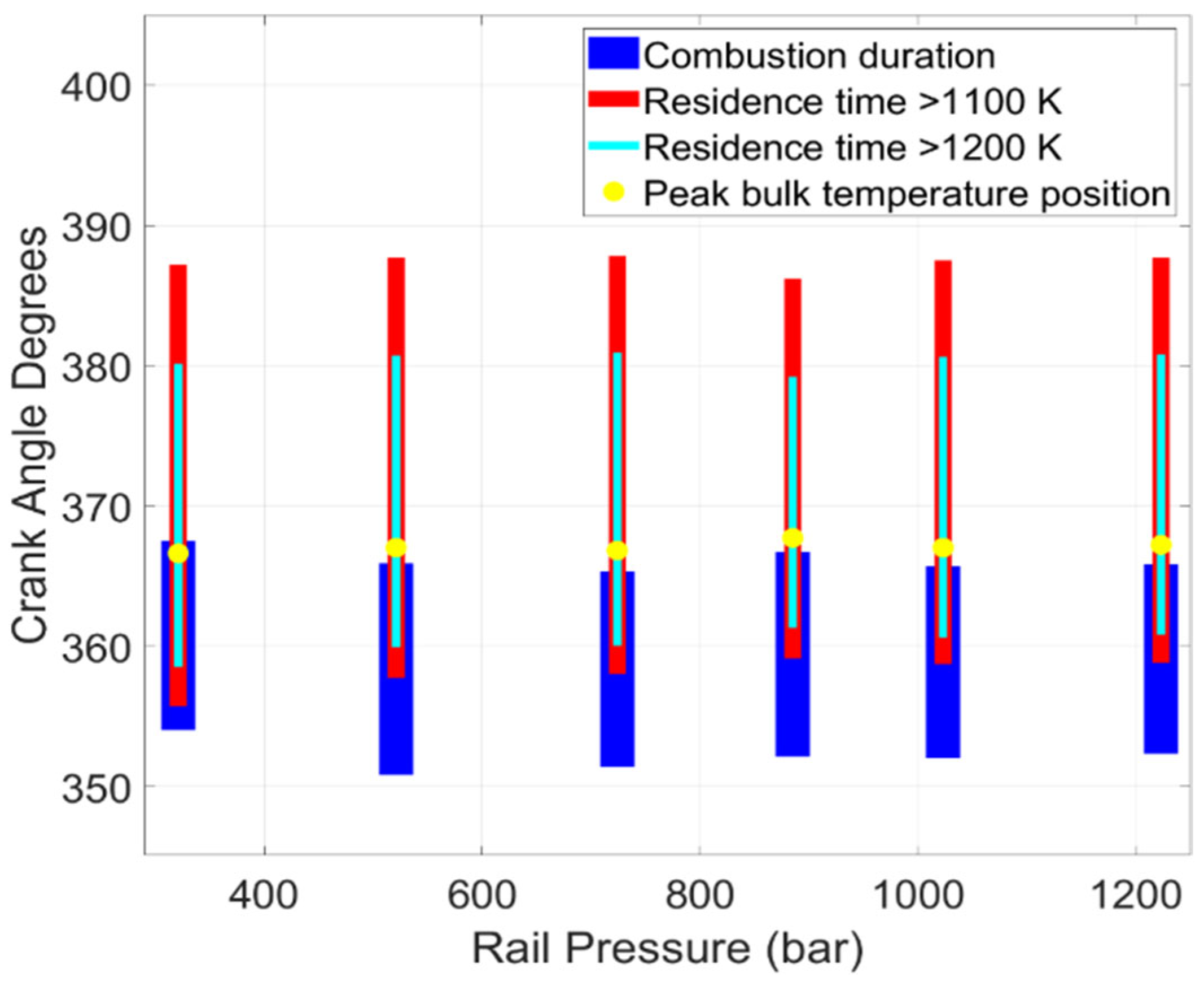
As rail pressure was increased, NOx emissions decreased exponentially for both diesel–propane and POMDME–propane as shown in Figure 21 and Figure 22. This is due to the increased air entrainment within the HRF jet, which in turn leads to better in-cylinder mixing and lower local temperatures within the cylinder. While HC remained relatively invariant, CO emissions increased with increasing rail pressure. Again, this is likely related to delayed combustion phasing (CA50) due to increased in-cylinder mixing at higher rail pressures. The CO to CO2 conversion needs significant residence times at high temperatures, and with delayed combustion phasing, it is possible that sufficient time was not available for CO to oxidize fully to CO2. This hypothesis is supported by the trends shown in Figure 23, as combustion for rail pressures above 800 bar was phased similarly, accompanied by similar ISCO emissions. However, as seen from Figure 24, POMDME–propane operation does not exhibit a similar CA50 trend.
Figure 21.
Rail pressure sweep emissions data (diesel–propane) at 1339 rpm, 5 bar IMEPg, 1.5 bar boost, and 70 PES.
Figure 22.
Rail pressure sweep emissions data (POMDME–propane) at 1339 rpm, 5 bar IMEPg, 1.5 bar boost, and 70 PES.
Figure 23.
Rail pressure sweep ISCO vs. CA50 (Diesel-Propane) at 1339 rpm, 5 bar IMEPg, 1.5 bar boost, and 70 PES.
Figure 24.
Rail pressure sweep ISCO vs. CA50 (POMDME-Propane) at 1339 rpm, 5 bar IMEPg, 1.5 bar boost, and 70 PES.
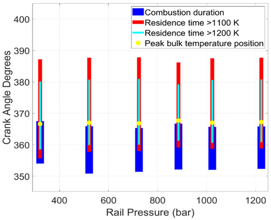
The residence time plots shown in Figure 25 and Figure 26 corroborate this as well, with similar residence times for higher rail pressures. While both 700 and 900 bar rail pressures had similar emissions, 700 bar rail pressure was chosen for further experiments since lower pressures lead to lower parasitic losses for the engine. For POMDME, significant emissions variations were observed with rail pressure; therefore, a rail pressure of 500 bar was selected for further sweeps.
Figure 25.
Rail pressure sweep residence time plots (diesel–propane) at 1339 rpm, 5 bar IMEPg, 1.5 bar boost, and 70 PES.
Figure 26.
Rail pressure sweep residence time plots (POMDME–propane) at 1339 rpm, 5 bar IMEPg, 1.5 bar boost, and 70 PES.
5.5. Coupled Injection Sweep
A coupled injection sweep of SOI1 and SOI2 together (with a fixed dwell of 5 CAD for diesel–propane and 6 CAD for POMDME-propane) was performed with other parameters fixed as described previously. Once again, SOI1 durations were held constant while SOI2 was adjusted to maintain IMEPg ~5 bar. Although Figure 27 and Figure 28 present data in terms of SOI1, it must be noted that SOI2 was also varied by the same CAD to maintain a fixed dwell between the two injection events.
Figure 27.
Coupled injection sweep emissions data (diesel–propane) at 1339 rpm, 5 bar IMEPg, 1.5 bar boost, and 70 PES.
Figure 28.
Coupled injection sweep emissions data (POMDME–propane) at 1339 rpm, 5 bar IMEPg, 1.5 bar boost, and 70 PES.
It was found that delaying the injection events slightly led to significant CO reductions, while only slightly penalizing NOx emissions. During the sweep, HC emissions remained relatively invariant but NOx increased for both fueling combinations and still remained well below 1 g/kWh. Therefore, the CO reductions were the decisive factor in choosing the SOI1 values of 317 CAD for diesel—propane and 322 CAD for POMDME–propane combustion for further testing.
5.6. Boost Pressure Sweep
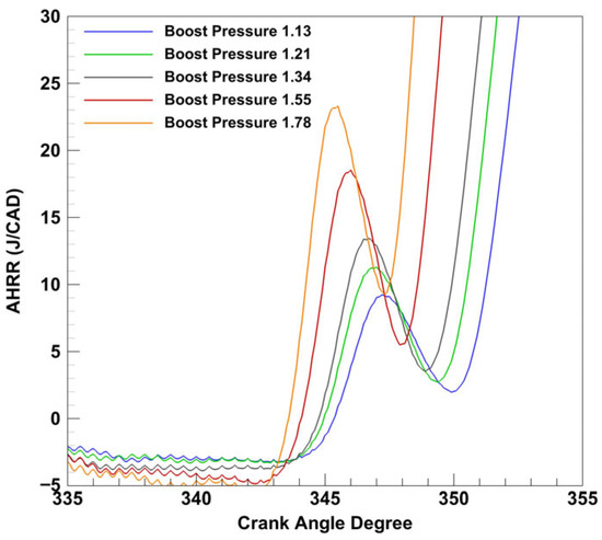
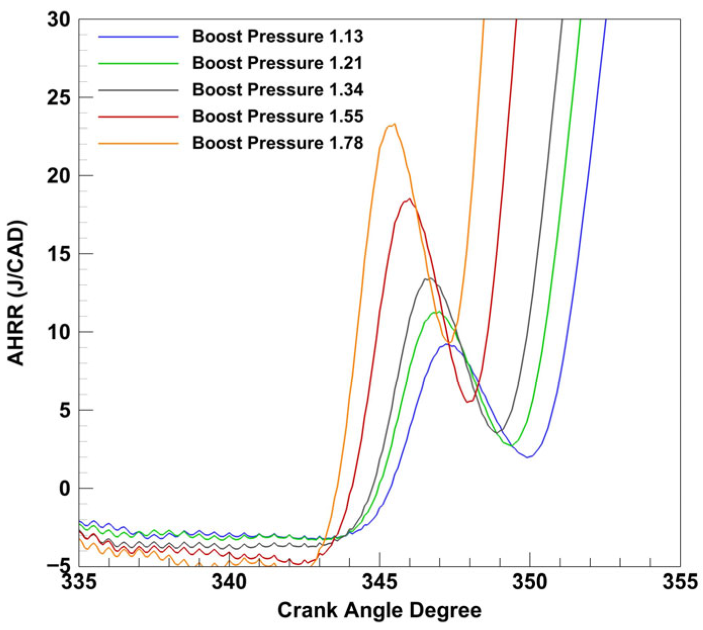
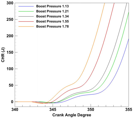
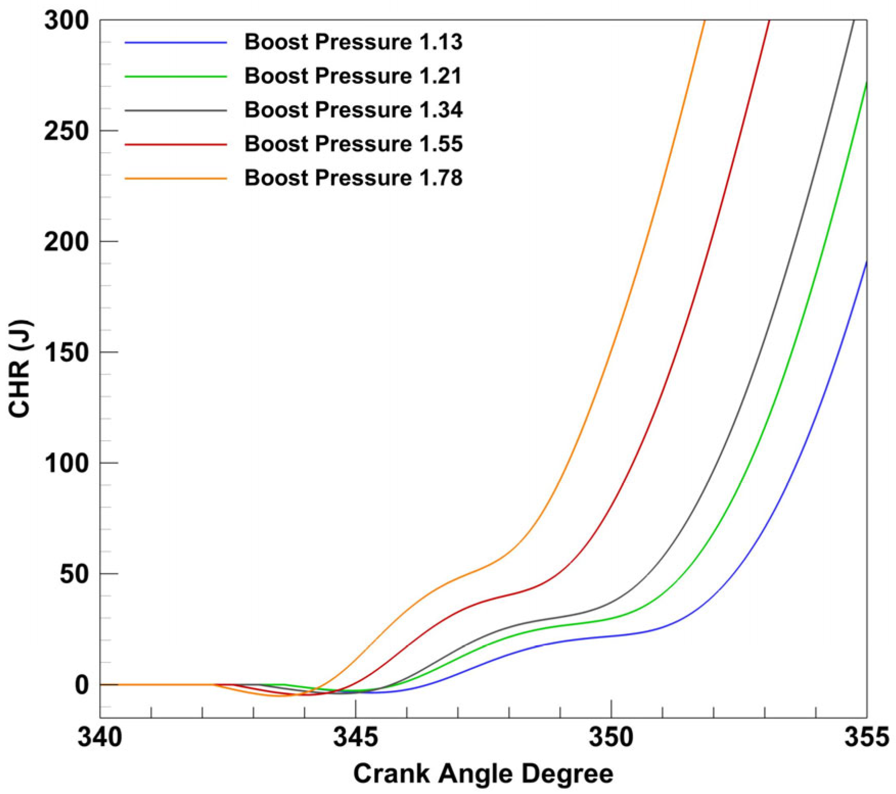
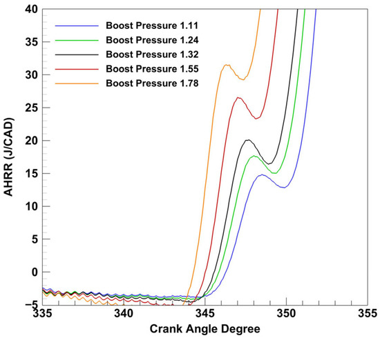
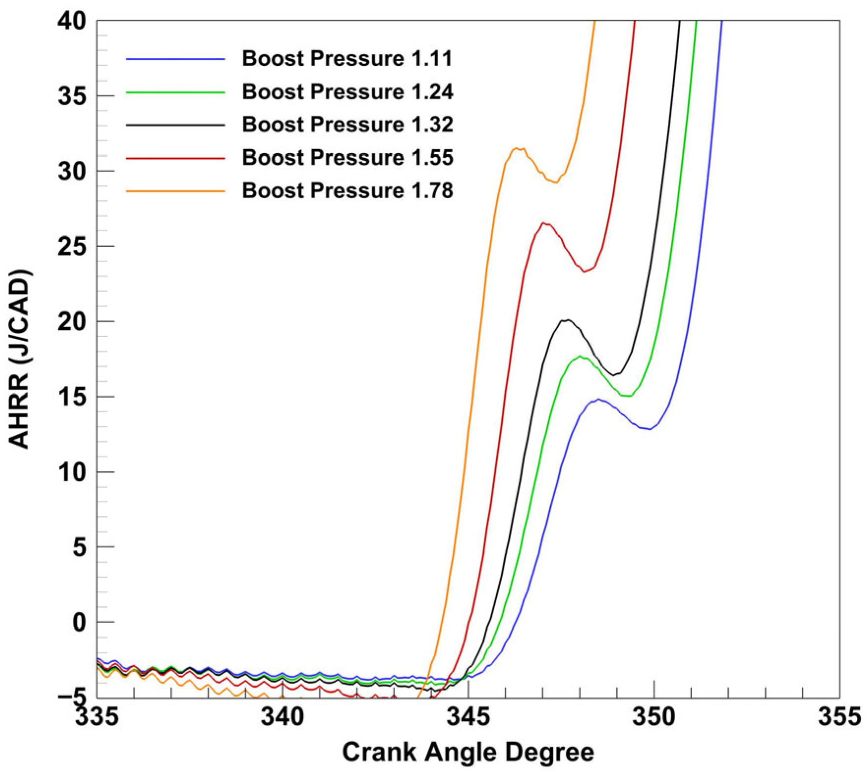
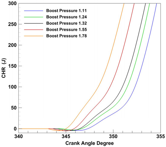
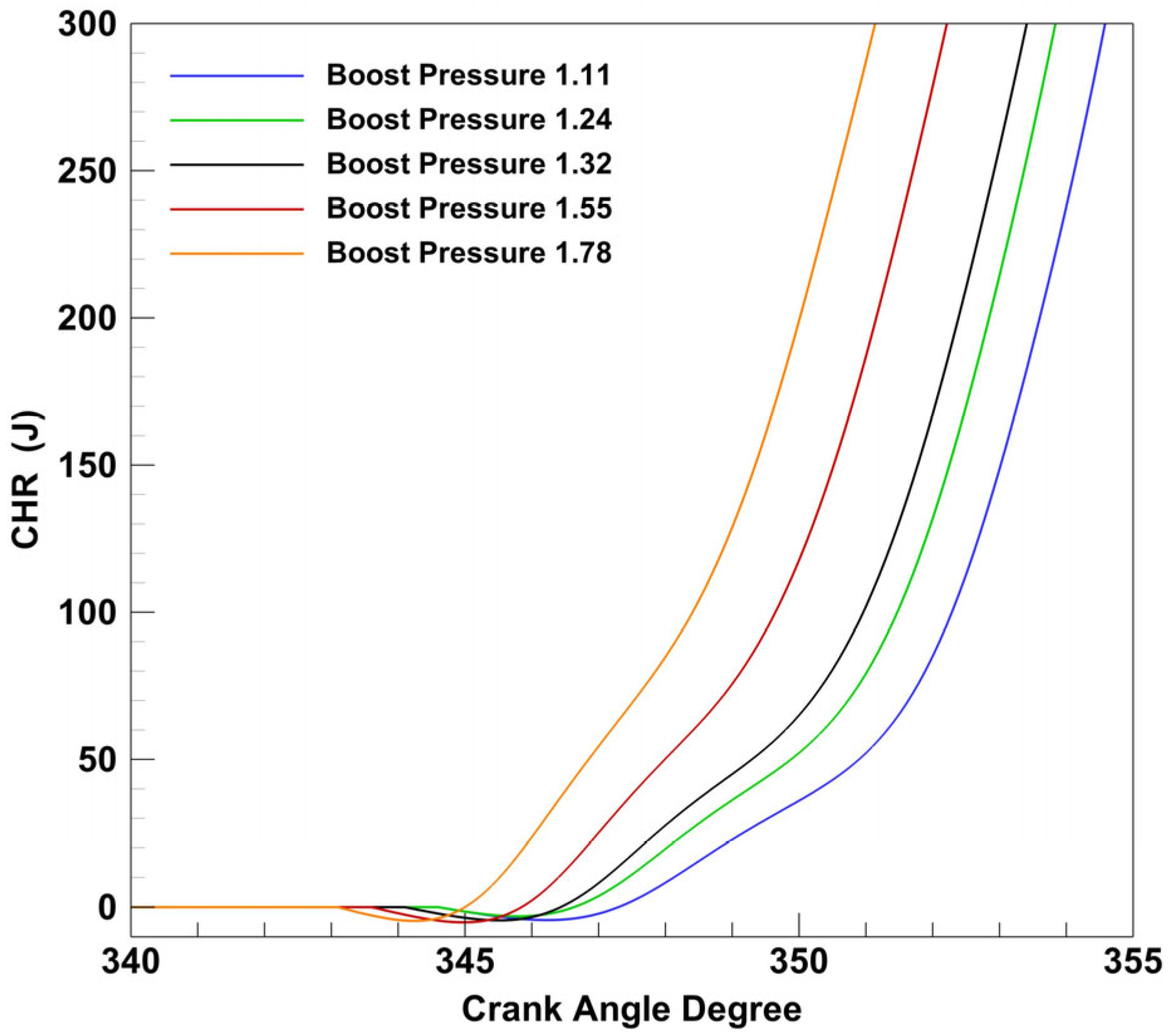
Previous studies (e.g., [13,23]) have shown that intake boost pressure has a strong effect on dual fuel combustion, especially emissions. For this study, the boost pressure was varied on either side of the base value of 1.5 bar. With increasing boost pressure, the LTHR portion of combustion both increased in magnitude and occurred earlier in the cycle at lower temperatures, as seen in Figure 29. This same trend was not observed during previous experiments on the same SCRE at the same speed/load conditions with natural gas as the LRF and diesel/POMDME as the HRFs [23]. This indicates that propane properties likely influenced LTHR differently than natural gas. Propane contains multiple low-temperature oxidation pathways (not present in methane) that have been studied in some detail [31]. It is hypothesized that at higher boost pressures these low temperature reaction pathways become more significant and have a greater impact upon the LTHR. The cumulative heat release curves during LTHR are plotted in Figure 30. Similar trends are observed in the LTHR and cumulative LTHR curves for POMDME-propane dual fuel combustion as shown in Figure 31 and Figure 32, respectively. It is apparent that a greater portion of the total heat release occurs during LTHR at higher boost pressures, even though total heat release values only fluctuated by ~2% at the end of combustion. This observed phenomenon lends credence to the proposed explanation as to why higher boost pressures have greater and more advanced LTHR curves; however, further detailed chemical kinetic investigations may be needed to verify this hypothesis.
Figure 29.
Boost pressure sweep LTHR curves (diesel–propane) at 1339 rpm, 5 bar IMEPg, and 70 PES.
Figure 30.
Boost pressure sweep LTHR cumulative heat release rate (diesel–propane) at 1339 rpm, 5 bar IMEPg, and 70 PES.
Figure 31.
Boost pressure sweep LTHR curves (POMDME–propane) at 1339 rpm, 5 bar IMEPg, and 70 PES.
Figure 32.
Boost pressure sweep LTHR cumulative heat release rate (POMDME–propane) at 1339 rpm, 5 bar IMEPg, and 70 PES.
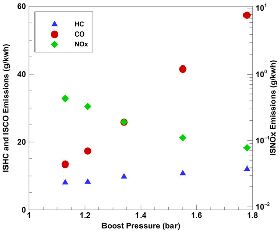
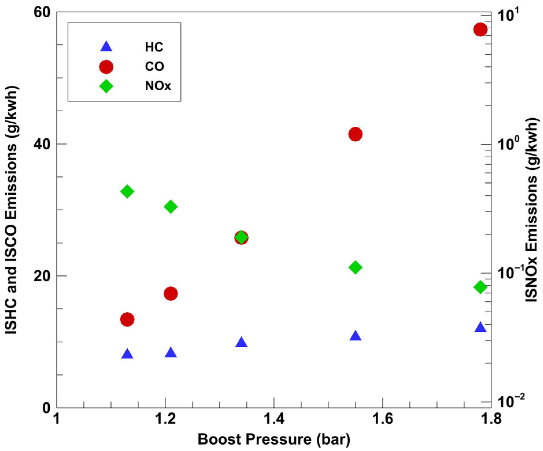
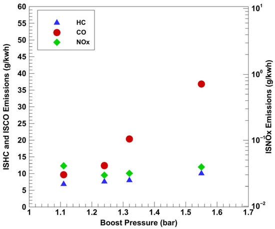
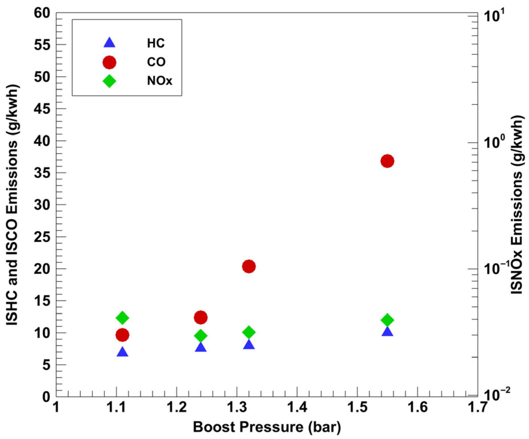
Emissions results from this sweep are presented in Figure 33 and Figure 34. As boost pressure increased, NOx decreased noticeably for diesel–propane but was relatively low and invariant for POMDME–propane. While it is possible that mixture overleaning at higher boost pressures could have contributed to lower local temperatures and lower NOx for diesel–propane, the higher MPRR values obtained at higher boost further complicate the explanation. Also, at this time, it is not clear why NOx remained relatively low and invariant for POMDME–propane.
Figure 33.
Boost pressure sweep emissions data (diesel–propane) at 1339 rpm, 5 bar IMEPg, and 70 PES.
Figure 34.
Boost pressure sweep emissions data (POMDME–propane) at 1339 rpm, 5 bar IMEPg, and 70 PES.
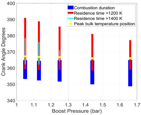
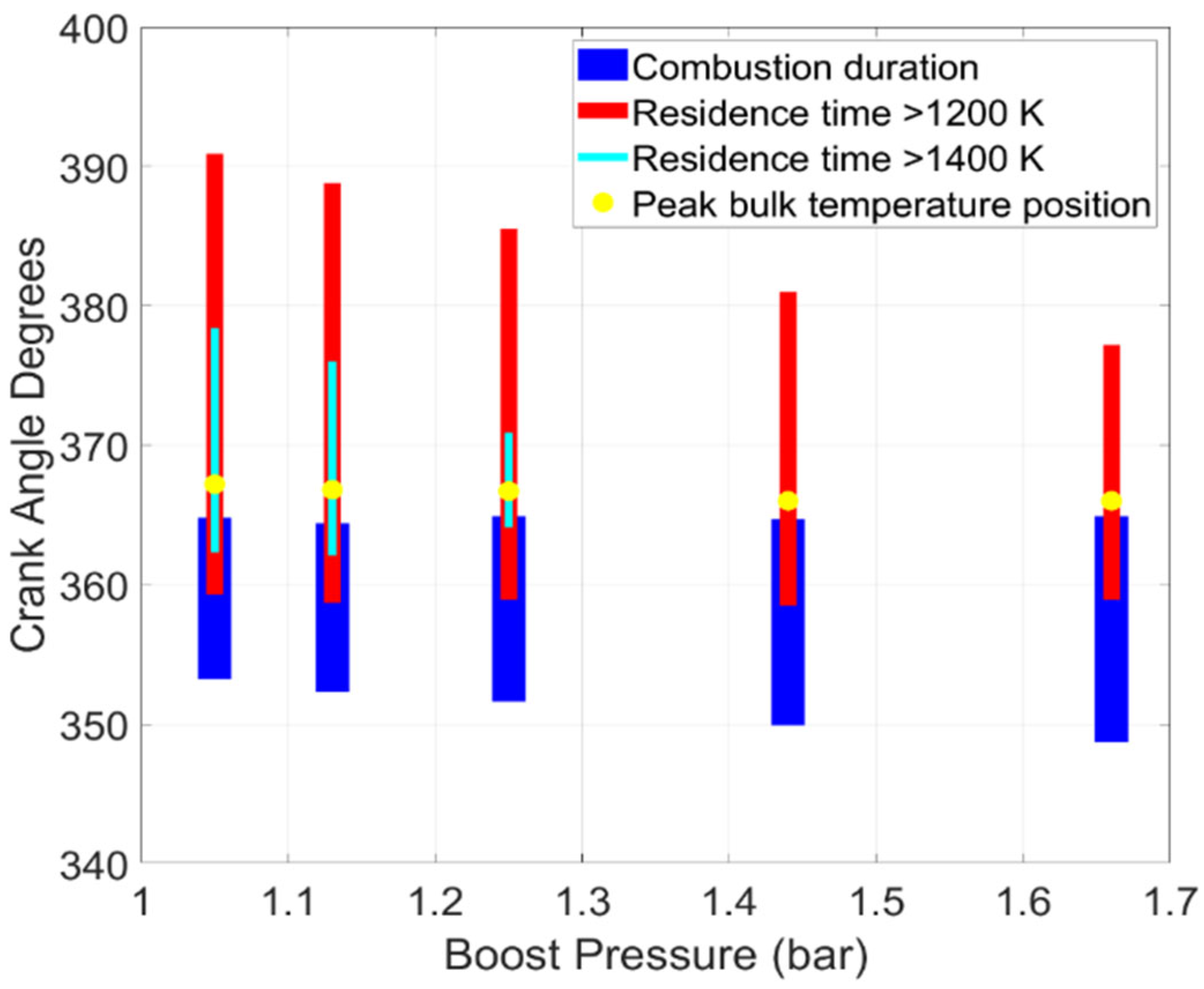
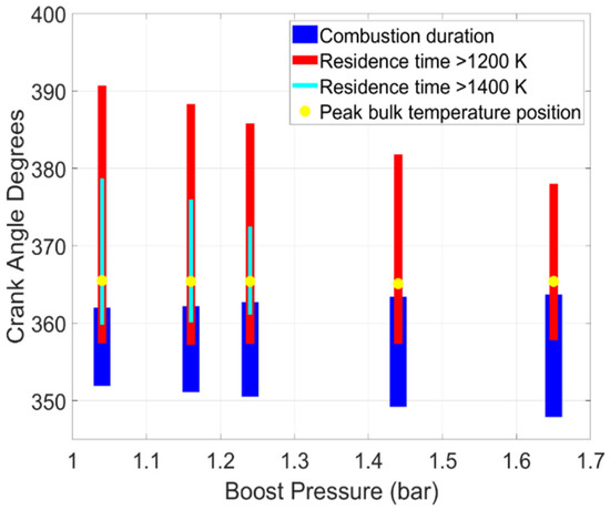
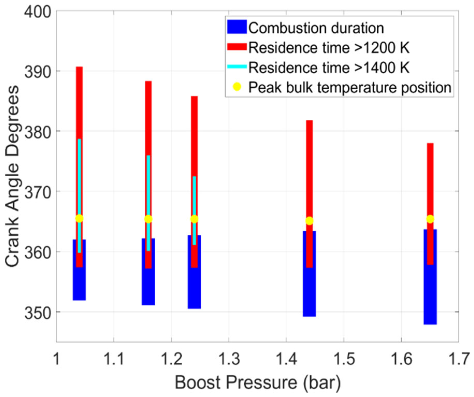
CO emissions decreased exponentially as boost pressure was reduced, a trend attributable to richer in-cylinder equivalence ratios and higher bulk gas temperatures persisting longer during and after the combustion process as evident from the residence time plots shown in Figure 35 and Figure 36. As discussed before, longer residence times of higher bulk gas temperatures allow for more complete CO oxidation into CO2. By comparison, HC emissions showed only a slight decrease with decreasing boost pressures.
Figure 35.
Boost pressure sweep residence rime plots (diesel–propane) at 1339 rpm, 5 bar IMEPg, and 70 PES.
Figure 36.
Boost pressure sweep residence time plots (POMDME–propane) at 1339 rpm, 5 bar IMEPg, and 70 PES.
Overall, since lower boost pressures led to much lower CO emissions while yet maintaining NOx emissions below 1 g/kWh, boost pressures of 1.1 bar and 1.05 bar were selected as most appropriate for diesel–propane and POMDME–propane combustion at these operating conditions. In general, lower boost pressures are desirable for engine operation as they reduce the need for turbocharging, which becomes even more challenging at the relatively low exhaust temperatures typical of dual fuel combustion with early SOIs.
5.7. Final PES Sweep
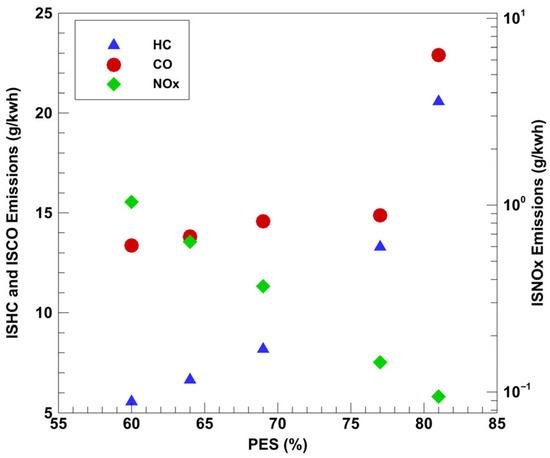
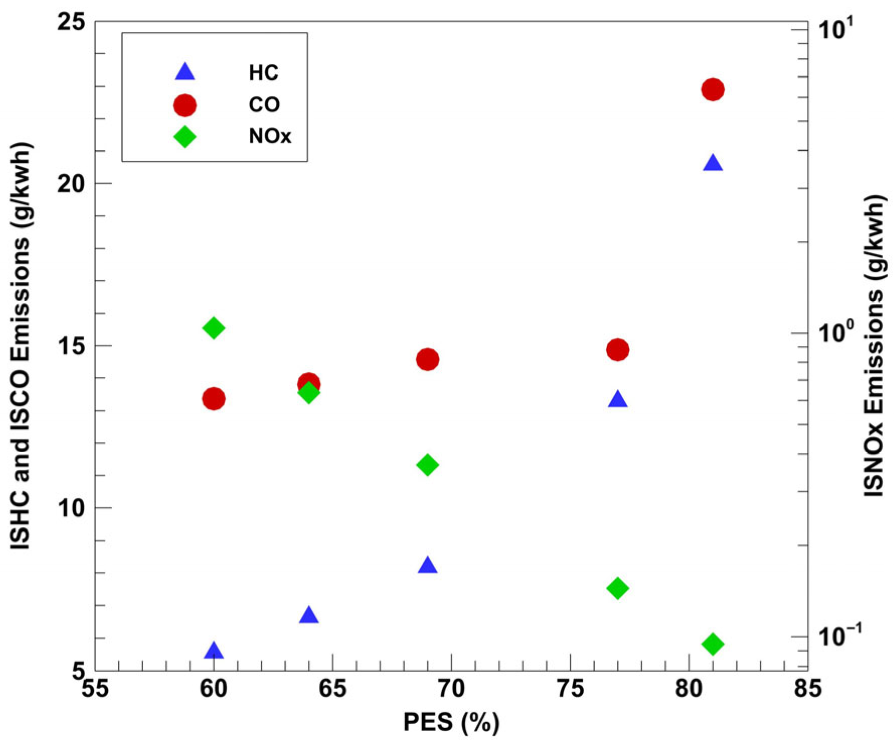
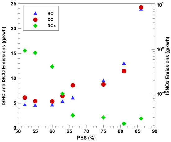
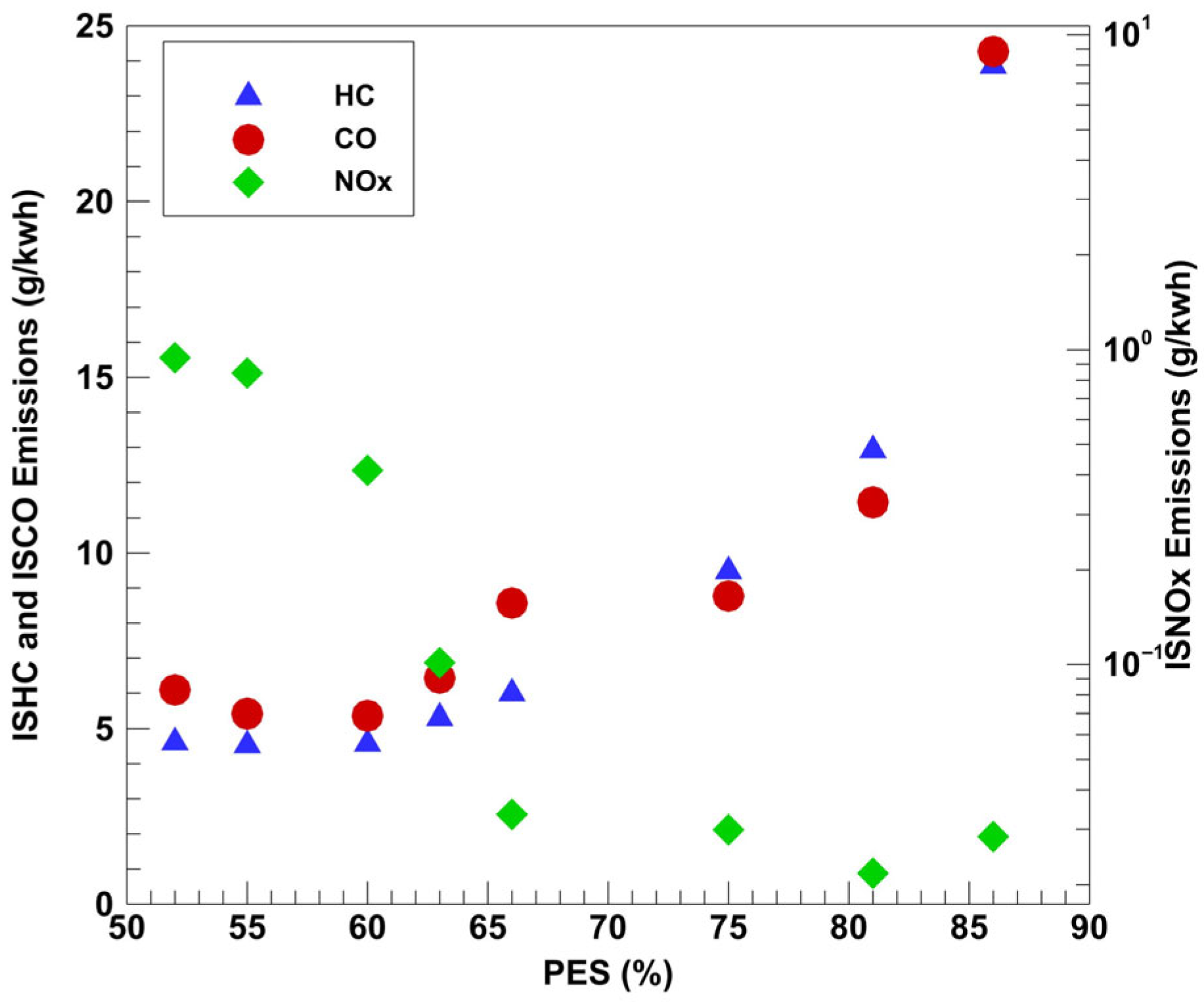
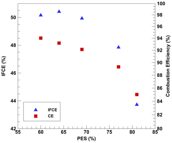
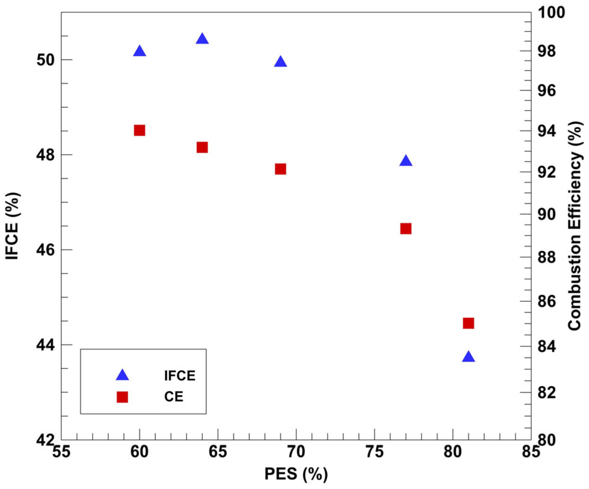
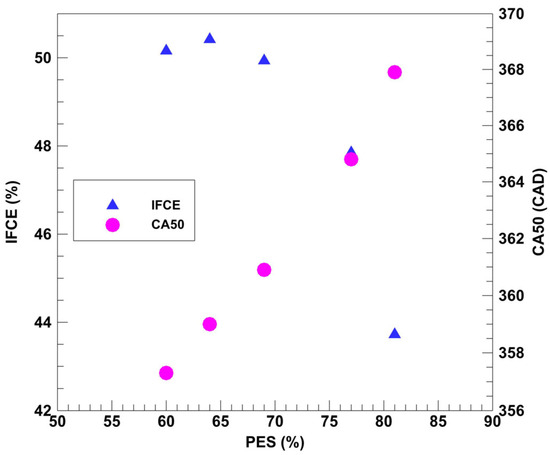
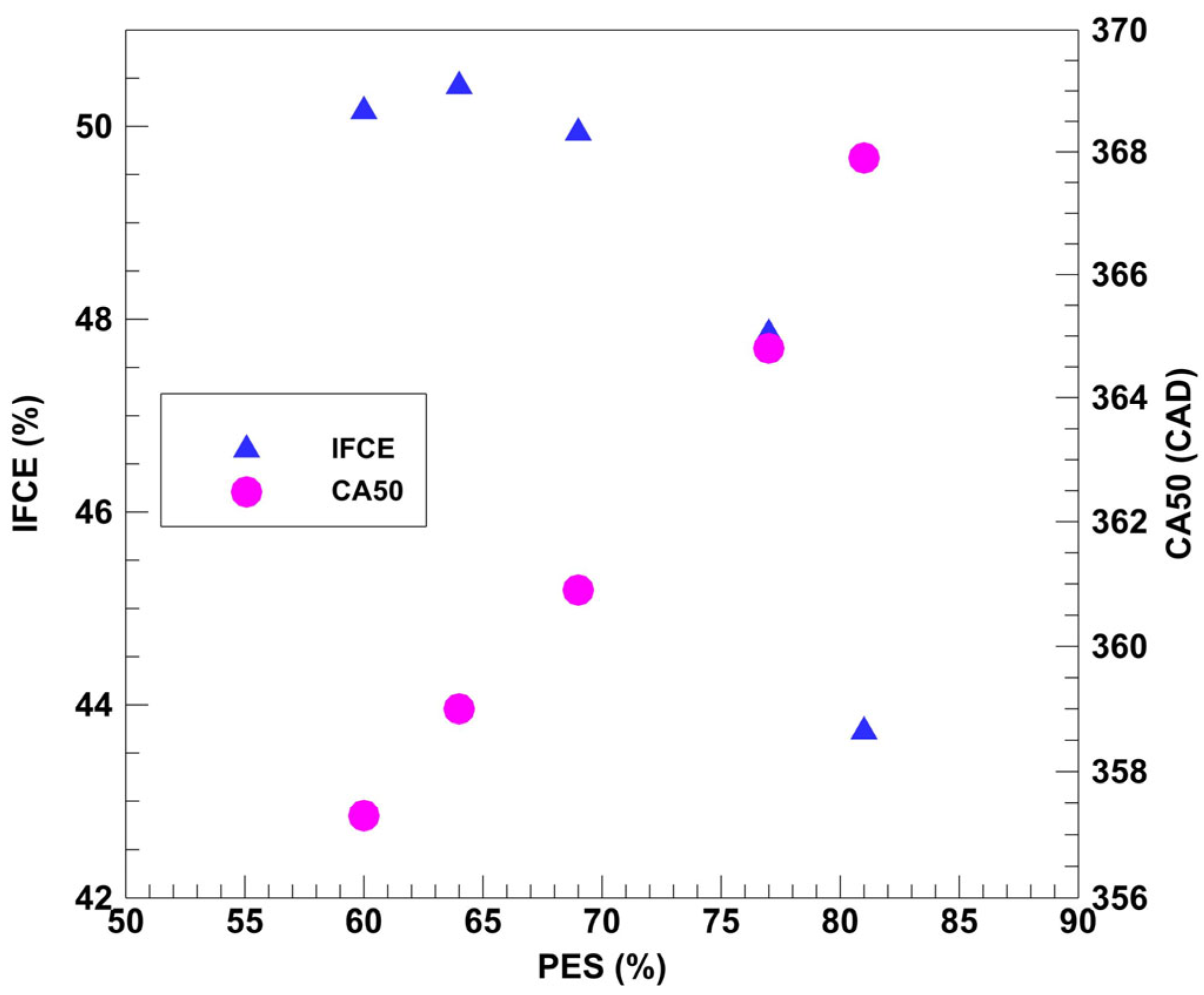
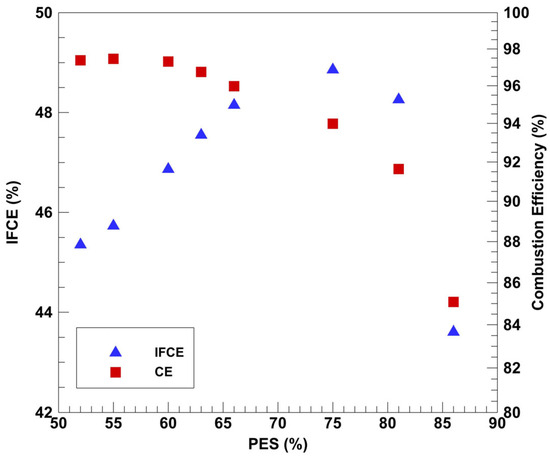
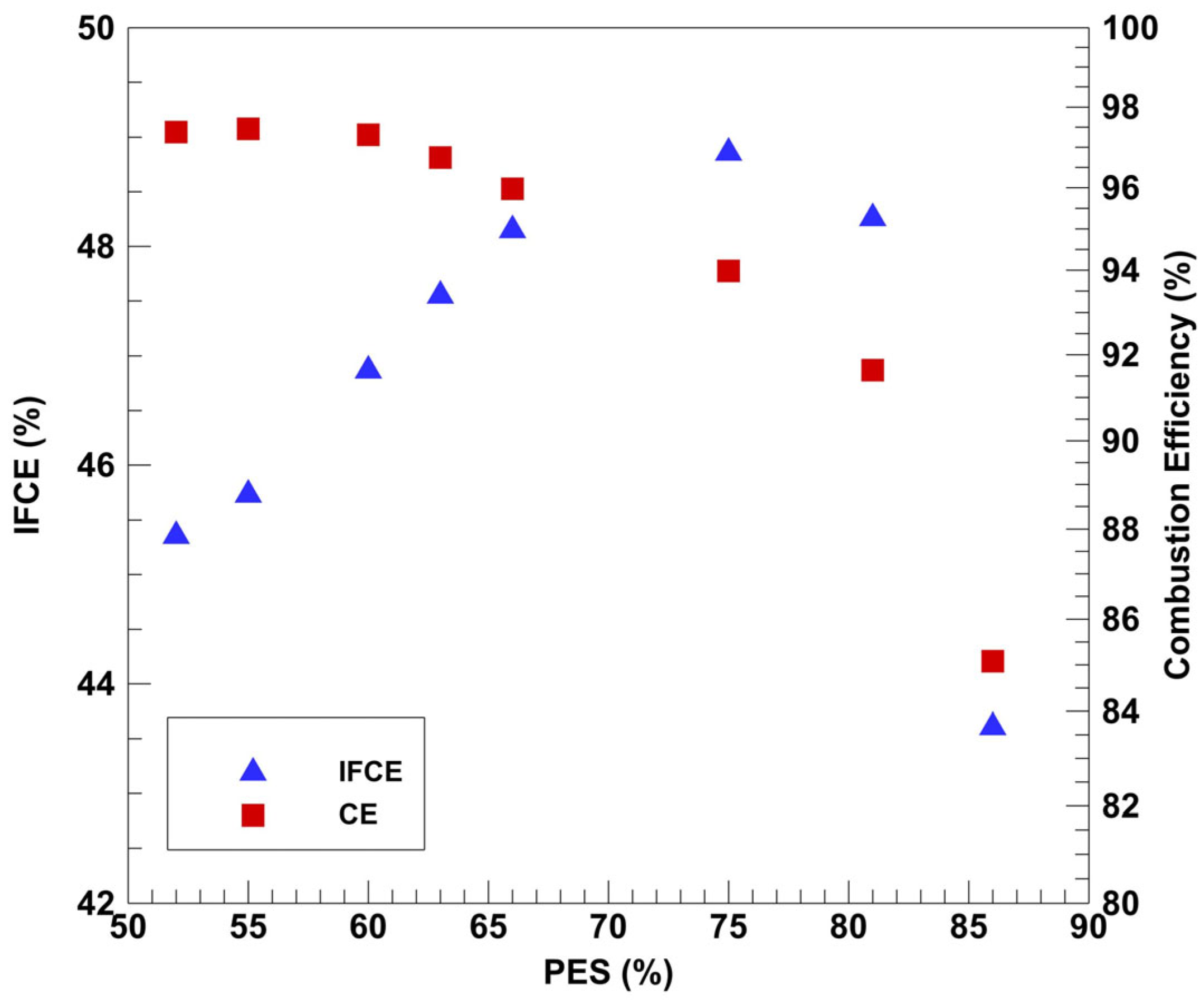
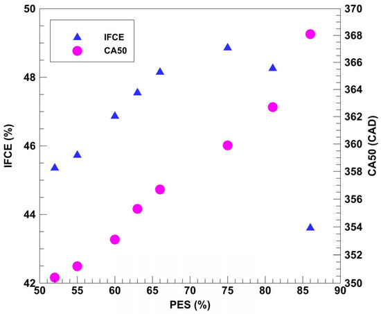
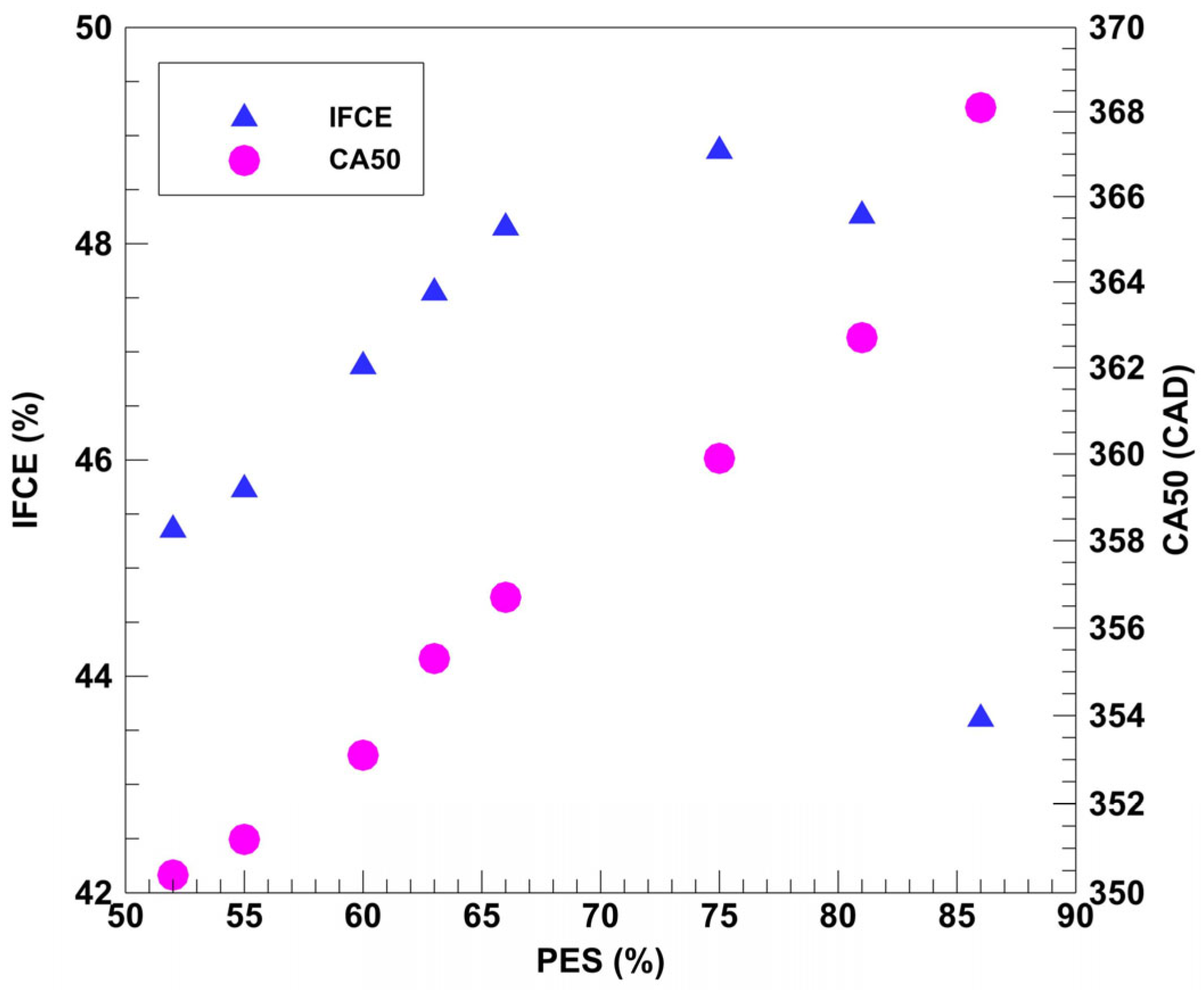
After completing the various parametric sweeps, one final PES sweep was conducted to maximize the energy percentage supplied by propane while improving efficiency and/or emissions. As the PES was increased from its baseline value of 70%, COV surpassed the global limit set at 5%. On the other hand, as PES was decreased to 60%, the global ISNOx limit of 1 g/kW-hr was exceeded. Figure 37 and Figure 38 show the NOx, HC, and CO trends for diesel–propane and POMDME–propane dual fuel combustion. In general, as PES was increased, NOx emissions decreased while CO and HC emissions increased for both dual fuel combinations. On the other hand, Figure 39 and Figure 40 present IFCE and combustion trends for diesel-propane and Figure 41 and Figure 42 present the same trends for POMDME-propane combustion. While both IFCE and combustion efficiency decreased with increasing PES for diesel–propane combustion (c.f., Figure 39), the IFCE peaked at intermediate PES values for POMDME–propane combustion as shown in Figure 41. The IFCE trends may be explained based on the CA50 phasing for both dual fuel combinations (c.f., Figure 40 and Figure 42). In general, CA50 phased closer to TDC led to higher IFCE and vice versa. Equally important, late CA50 phasing (i.e., well after TDC) led to higher CO and HC emissions as well as higher COV of IMEP (greater engine instability), and therefore, lower combustion efficiencies. In summary, there appears to be an “optimal PES range” between 65% and 70% at which the best efficiency–emissions tradeoffs are obtained.
Figure 37.
Double injection PES sweep emissions data (diesel–propane) at 1339 rpm, 5 bar IMEPg, and 1.5 bar boost.
Figure 38.
Double injection PES sweep emissions data (POMDME–propane) at 1339 rpm, 5 bar IMEPg, and 1.5 bar boost.
Figure 39.
Double injection PES sweep efficiencies (diesel–propane) at 1339 rpm, 5 bar IMEPg, and 1.5 bar boost.
Figure 40.
Double injection PES sweep combustion phasing (diesel–propane) at 1339 rpm, 5 bar IMEPg, and 1.5 bar boost.
Figure 41.
Double injection PES sweep efficiencies (POMDME–propane) at 1339 rpm, 5 bar IMEPg, and 1.5 bar boost.
Figure 42.
Double injection PES sweep combustion phasing (POMDME–propane) at 1339 rpm, 5 bar IMEPg, and 1.5 bar boost.
6. Summary and Conclusions
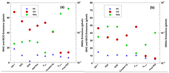
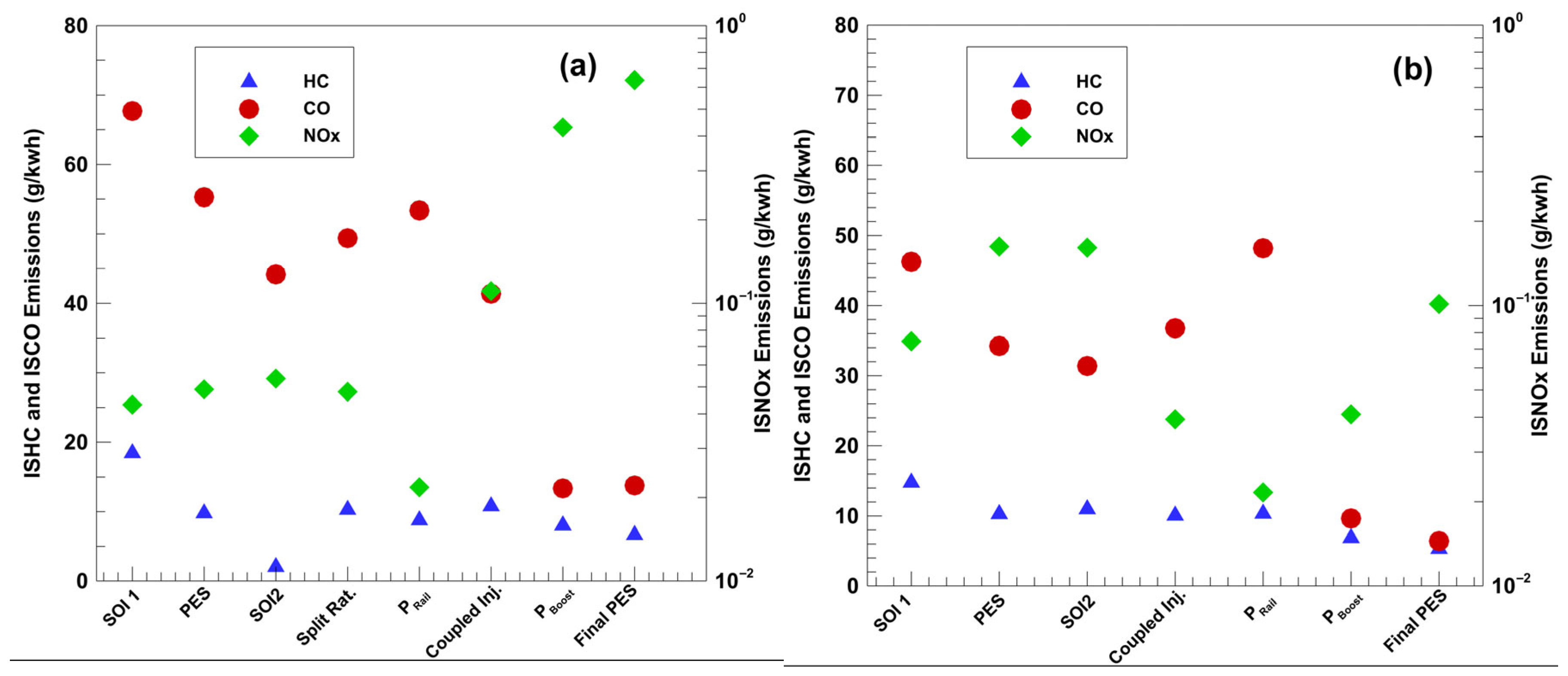
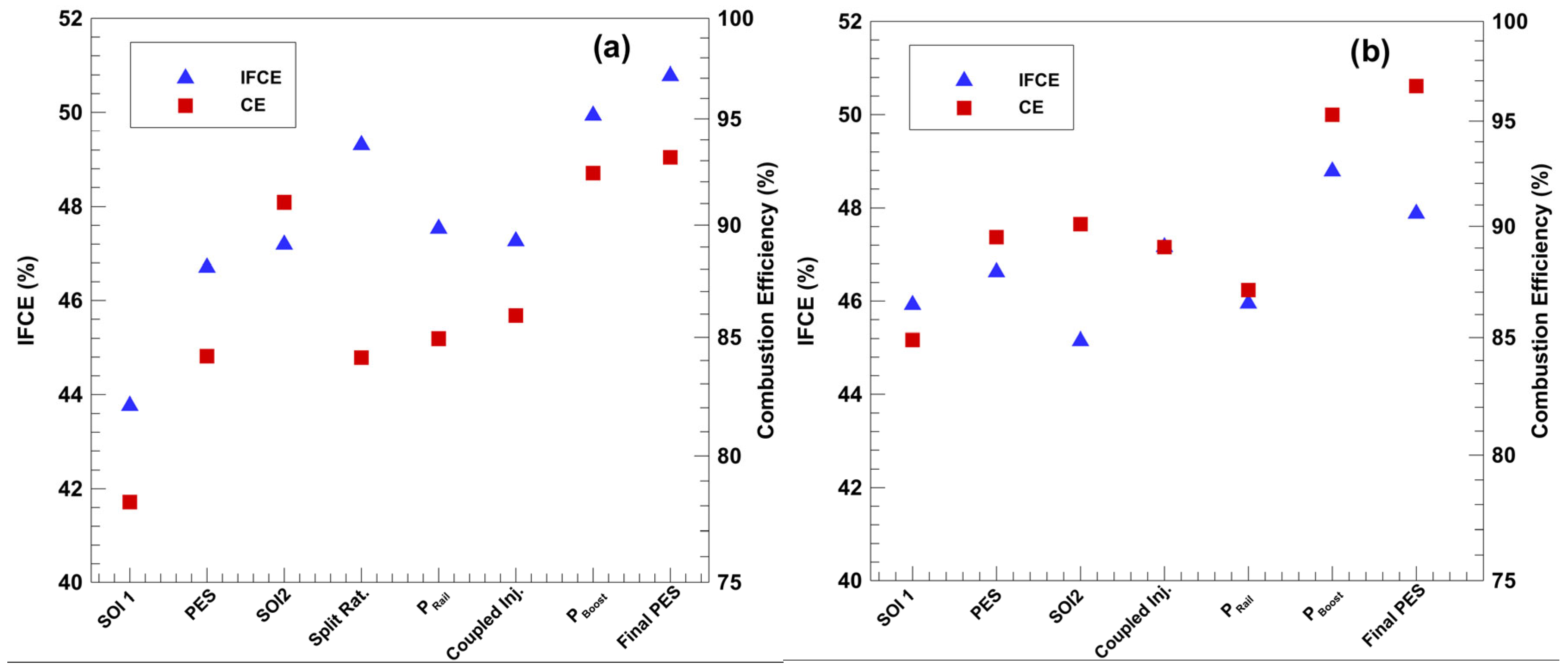
This work presents experimental results for low load diesel–propane and POMDME–propane dual fuel combustion for a heavy-duty single-cylinder research engine at 5 bar IMEPg and 1339 rpm. The experimental methodology, designed after conducting an extensive literature review, aimed to reduce engine-out NOx, HC, and CO emissions at advanced SOI timings. The following parameters were used to reduce HC, CO, and NOx while improving IFCE: SOI1, SOI2, PES, injection split ratio, rail pressure, and boost pressure with global limits set at 1 g/kWh NOx emissions, 10 bar/CAD maximum pressure rise rate, and a COV of IMEP under 5%. A graphical summary of the best-case emissions and efficiencies for each parametric sweep for diesel–propane and POMDME–propane dual fuel combustion are shown in Figure 43 and Figure 44, respectively.
Figure 43.
Best case emissions for (a) diesel–propane and (b) POMDME–propane dual fuel combustion.
Figure 44.
Best case efficiencies for (a) diesel–propane and (b) POMDME–propane dual fuel combustion.
Table 4 and Table 5 summarize the best-case performance and emissions values and percentage improvements for diesel–propane and POMDME–propane dual fuel combustion, respectively, compared to the corresponding baseline values for pure diesel and unoptimized dual fuel combustion. The optimal operating conditions for 5 bar IMEPg load and 1339 rpm speed are shown in Table 6.
Table 4.
Overall engine emissions and performance comparisons for diesel–propane.
Table 5.
Overall engine emissions and performance comparisons for POMDME–propane.
Table 6.
Operating parameters for identified best points at 5 bar IMEPg and 1339 rpm.
The experimental results support the following general conclusions regarding low load diesel–propane and POMDME–propane dual fuel combustion on the heavy-duty SCRE:
- POMDME–propane combustion never produced any significant amount of soot measured by the AVL 415S smokemeter (near-zero FSN at all conditions);
- By co-optimizing multiple operating parameters, engine-out HC, CO, and NOx emissions were reduced for both diesel–propane and POMDME–propane combustion;
- Splitting the injection event into two separate events reduced both HC and CO emissions:
- Injection split ratio had a negligible impact upon emissions and efficiencies under these operating conditions;
- Reducing intake boost pressure significantly decreased engine-out CO emissions;
Author Contributions
Conceptualization, A.L.P., K.K.S. and S.R.K.; methodology, A.L.P.; software, A.N.; validation, A.L.P., K.R.P. and A.N.; formal analysis, A.L.P.; investigation, A.L.P., K.R.P. and A.N.; resources, K.K.S. and S.R.K.; data curation, A.L.P., K.R.P. and A.N.; writing—original draft preparation, A.L.P., K.R.P. and A.N.; writing—review and editing, K.K.S. and S.R.K.; visualization, A.L.P.; supervision, K.K.S. and S.R.K.; project administration, K.K.S. and S.R.K.; funding acquisition, K.K.S. and S.R.K. All authors have read and agreed to the published version of the manuscript.
Funding
This research received no external funding.
Data Availability Statement
The original contributions presented in this study are included in the article. Further inquiries can be directed to the corresponding author.
Acknowledgments
The authors acknowledge the assistance provided by Hariraja Thothadri, a student in the Engines and Combustion Laboratory at The University of Alabama, in updating several figures in the revised manuscript.
Conflicts of Interest
Author Austin Leo Pearson was employed by the company Sargeant and Lundy, Chicago, IL. The remaining authors declare that the research was conducted in the absence of any commercial or financial relationships that could be construed as a potential conflict of interest.
References
- Energy Information Administration. Hydrocarbon Gas Liquids Explained: Where Do Hydrocarbon Gas Liquids Come from? 2023. Available online: https://www.eia.gov/energyexplained/hydrocarbon-gas-liquids/where-do-hydrocarbon-gas-liquids-come-from-in-depth.php (accessed on 9 February 2026).
- Dec, J. A Conceptual Model of DI Diesel Combustion Based on Laser-Sheet Imaging; 970873; SAE Technical Paper: Warrendale, PA, USA, 1997. [Google Scholar] [CrossRef] [Scilit]
- Lee, J.-H.; Lida, N. Combustion of diesel spray injected into reacting atmosphere of propane-air homogeneous mixture. Int. J. Engine Res. 2001, 2, 69–80. [Google Scholar] [CrossRef] [Scilit]
- Abd Alla, G.H.; Soliman, H.A.; Badr, O.A.; Abd Rabbo, M.F. Effect of injection timing on the performance of a dual fuel engine. Energy Convers. Manag. 2002, 43, 269–277. [Google Scholar] [CrossRef] [Scilit]
- Abd Alla, G.H.; Soliman, H.A.; Badr, O.A.; Abd Rabbo, M.F. Effect of pilot fuel quantity on the performance of a dual fuel engine. Energy Convers. Manag. 2000, 41, 559–572. [Google Scholar] [CrossRef] [Scilit]
- Selim Mohamed, Y.E. Effect of engine parameters and gaseous fuel type on the cyclic variability of dual fuel engines. Fuel 2005, 84, 961–971. [Google Scholar] [CrossRef] [Scilit]
- Stewart, J.; Clarke, A.; Chen, R. An experimental study of the dual-fuel performance of a small compression ignition diesel engine operating with three gaseous fuels. Proc. Inst. Mech. Eng. Part D J. Automob. Eng. 2007, 221, 943–956. [Google Scholar] [CrossRef] [Scilit]
- Saanum, I.; Bysveen, M.; Hustad, J.E. Study of Particulate Matter-, NOx-and Hydrocarbon Emissions from a Diesel Engine Fueled with Diesel Oil and Biodiesel with Fumigation of Hydrogen, Methane and Propane; 2008-01-1809; SAE Technical Paper: Warrendale, PA, USA, 2008. [Google Scholar]
- Saleh, H.E. Effect of variation in LPG composition on emissions and performance in a dual fuel diesel engine. Fuel 2008, 87, 3031–3039. [Google Scholar] [CrossRef] [Scilit]
- Ashok, B.; Denis Ashok, S.; Ramesh Kumar, C. LPG diesel dual fuel engine—A critical review. Alex. Eng. J. 2015, 54, 105–126. [Google Scholar] [CrossRef] [Scilit]
- Lata, D.B.; Misra, A.; Medhekar, S. Effect of hydrogen and LPG addition on the efficiency and emissions of a dual fuel diesel engine. Int. J. Hydrogen Energy 2012, 37, 6084–6096. [Google Scholar] [CrossRef] [Scilit]
- Lee, J.; Chu, S.; Cha, J.; Choi, H.; Min, K. Effect of the diesel injection strategy on the combustion and emissions of propane/diesel dual fuel premixed charge compression ignition engines. Energy 2015, 93, 1041–1052. [Google Scholar] [CrossRef] [Scilit]
- Krishnan, S.R.; Srinivasan, K.K.; Raihan, M.S. The effect of injection parameters and boost pressure on diesel-propane dual fuel low temperature combustion in a single-cylinder research engine. Fuel 2016, 184, 490–502. [Google Scholar] [CrossRef] [Scilit]
- Kang, J.; Chu, S.; Lee, J.; Kim, G.; Min, K. Effect of operating parameters on diesel/propane dual fuel premixed compression ignition in a diesel engine. Int. J. Automot. Technol. 2018, 19, 27–35. [Google Scholar] [CrossRef] [Scilit]
- Polk, A.C.; Carpenter, C.D.; Scott Guerry, E.; Dwivedi, U.; Srinivasan, K.K.; Krishnan, S.R.; Rowland, Z.L. Diesel-ignited propane dual fuel low temperature combustion in a heavy-duty diesel engine. J. Eng. Gas Turbines Power 2014, 136, 091509. [Google Scholar] [CrossRef] [Scilit]
- Marchionna, M.; Patrini, R.; Sanfilippo, D.; Migliavacca, G. Fundamental investigations on di-methyl ether (DME) as LPG substitute or make-up for domestic uses. Fuel Process. Technol. 2008, 89, 1255–1261. [Google Scholar] [CrossRef] [Scilit]
- Fleisch, T.H.; Basu, A.; Sills, R.A. Introduction and advancement of a new clean global fuel: The status of DME developments in China and beyond. J. Nat. Gas Sci. Eng. 2012, 9, 94–107. [Google Scholar] [CrossRef] [Scilit]
- Mochizuki, K.; Shima, T.; Suzuki, H.; Ishikawa, Y.; Iijima, A.; Yoshida, K.; Shoji, H. A Study of Supercharged HCCI Combustion Using Blended Fuels of Propane and DME; 2014-32-0005; SAE Technical Paper: Warrendale, PA, USA, 2014. [Google Scholar] [CrossRef] [Scilit]
- Prabhakar, B.; Jayaraman, S.; Vander Wal, R.; Boehman, A. Experimental studies of high efficiency combustion with fumigation of dimethyl ether and propane into diesel engine intake air. J. Eng. Gas Turbines Power 2015, 137, 041505. [Google Scholar] [CrossRef] [Scilit]
- Srna, A.; Barro, C.; Herrmann, K.; Möri, F.; Hutter, R.; Boulouchos, K. POMDME as an Alternative Pilot Fuel for Dual-Fuel Engines: Optical Study in a RCEM and Application in an Automotive Size Dual-Fuel Diesel Engine; SAE Technical Paper No. 2018-01-1734; Warrendale, PA, USA, 2018; Available online: https://saemobilus.sae.org/papers/pomdme-alternative-pilot-fuel-dual-fuel-engines-optical-study-a-rcem-application-automotive-size-dual-fuel-diesel-engine-2018-01-1734#citation (accessed on 20 February 2026). [CrossRef] [Scilit]
- García, A.; Monsalve-Serrano, J.; Villalta, D.; Guzman-Mendoza, M. Methanol and OMEx as fuel candidates to fulfill the potential EURO VII emissions regulation under dual-mode dual-fuel combustion. Fuel 2021, 287, 119548. [Google Scholar] [CrossRef] [Scilit]
- Benajes, J.; García, A.; Monsalve-Serrano, J.; Martínez-Boggio, S. Potential of using OMEx as substitute of diesel in the dual-fuel combustion mode to reduce the global CO2 emissions. Transp. Eng. 2020, 1, 100001. [Google Scholar] [CrossRef] [Scilit]
- Hariharan, D.; Partridge, K.; Narayanan, A.; Srinivasan, K.K.; Krishnan, S.R.; Anandaraman, N. Strategies for Reduced Engine-out HC, CO, and NOx Emissions in Diesel-Natural Gas and POMDME-Natural Gas Dual-Fuel Engine. SAE Int. J. Adv. Curr. Pract. Mobil. 2022, 4, 1264–1278. [Google Scholar] [CrossRef] [Scilit]
- International DME Association. DME Material Compatibility Overview; International DME Association: Washington, DC, USA, 2017. [Google Scholar]
- Heywood, J.B. Internal Combustion Engine Fundamentals; McGraw-Hill Education: Columbus, OH, USA, 2018. [Google Scholar]
- Chevron Corporation. Diesel Fuels Technical Review; Chevron: San Ramon, CA, USA, 2007. [Google Scholar]
- McBride, B.J. Coefficients for Calculating Thermodynamic and Transport Properties of Individual Species; National Aeronautics and Space Administration, Office of Management, Scientific and Technical Information Program: Hampton, VA, USA, 1993; Volume 4513. [Google Scholar]
- Pearson, A.L. Emissions Optimization of Propane Dual Fuel Combustion Ignited by Diesel and Polyoxymethylene Dimethyl Ether At Low Loads. Master’s Thesis, Department of Mechanical Engineering, The University of Alabama, Tuscaloosa, AL, USA, 2022. [Google Scholar]
- Sjöberg, M.; Dec, J.E. An investigation into lowest acceptable combustion temperatures for hydrocarbon fuels in HCCI engines. Proc. Combust. Inst. 2005, 30, 2719–2726. [Google Scholar] [CrossRef] [Scilit]
- Li, J.; Ling, X.; Liu, D.; Yang, W.; Zhou, D. Numerical study on double injection techniques in a gasoline and biodiesel fueled RCCI (reactivity controlled compression ignition) engine. Appl. Energy 2018, 211, 382–392. [Google Scholar] [CrossRef] [Scilit]
- Huynh, L.K.; Carstensen, H.-H.; Dean, A.M. Detailed modeling of low-temperature propane oxidation: 1. The role of the propyl+ O2 reaction. J. Phys. Chem. A 2010, 114, 6594–6607. [Google Scholar] [CrossRef] [Scilit] [PubMed]


Disclaimer/Publisher’s Note: The statements, opinions and data contained in all publications are solely those of the individual author(s) and contributor(s) and not of MDPI and/or the editor(s). MDPI and/or the editor(s) disclaim responsibility for any injury to people or property resulting from any ideas, methods, instructions or products referred to in the content. |
© 2026 by the authors. Licensee MDPI, Basel, Switzerland. This article is an open access article distributed under the terms and conditions of the Creative Commons Attribution (CC BY) license.