


Abstract
The increasing penetration of inverter-based resources (IBRs) has been reducing system inertia and intensifying frequency stability challenges. Hence, various grid demands have been imposed on grid-connected systems, e.g., requiring the provision of an auxiliary service to the grid. In this context, this paper investigates the provision of synthesized inertia from the DC-link capacitors in grid-connected photovoltaic (PV) systems. For this configuration, the PV converter adopts a frequency–voltage droop control (FVDC) strategy, while a virtual synchronous generator (VSG) is employed on the grid side to emulate a synchronous generator, to enable the DC-link energy to contribute to primary frequency support. To quantify the virtual inertia and evaluate the closed-loop stability, a small-signal model of the inverter system is established. An eigenvalue analysis reveals that while increasing the DC-link voltage or capacitance enhances the achievable virtual inertia, it simultaneously narrows the stability margin. As such, comparative stability assessments under different parameter settings are performed, highlighting the distinct impacts of the DC-link voltages and capacitances on the emulated inertia and stability margins. The study provides insights into the maximum virtual inertia achievable via DC-link capacitors and offers practical guidelines for coordinating the controller and DC-link design to enhance frequency robustness in low-inertia power systems. Real-time hardware-in-the-loop (RT-HIL) tests validate the analytical findings.
1. Introduction
The level of synchronous inertia in modern power systems has been markedly declining by the rapid growth of inverter-based resources (IBRs), thereby posing challenges for frequency stability under disturbances [1,2]. Unlike synchronous generators (SGs), which inherently provide kinetic energy through their rotating masses, grid-connected photovoltaic (PV) systems are predominantly governed by maximum power point tracking (MPPT) algorithms and lack the ability to release or absorb energy rapidly during transients [3]. As a consequence, the high penetration of PV systems compromises grid frequency stability by elevating the rate of change of frequency (RoCoF) and weakening the system’s primary frequency response, thus posing severe challenges to grid stability in low-inertia conditions [4].
To address this issue, various control strategies such as power reserve control, synthetic inertia, and virtual synchronous generator (VSG) methods have emerged, allowing converter-interfaced renewable sources to actively participate in frequency regulation [5,6]. Among these approaches, utilizing DC-link capacitor energy has gained increasing attention due to its intrinsic fast response and independence from external energy storage elements [7,8].
Recent studies demonstrate that DC-link capacitors can provide virtual inertia, enhance synchronization, and support both grid-forming and grid-following converters in weak grids [9,10]. However, prior work mainly reports qualitative capabilities, without explicitly quantifying the maximum usable virtual inertia or its dependence on DC-link voltage, capacitance, and droop gain [11,12,13]. To overcome this limitation, a frequency–voltage droop control (FVDC) integrated within a VSG framework has emerged as an effective method to relate grid frequency deviations to DC-link voltage regulation, enabling both virtual inertia synthesis and automatic energy recovery [14,15]. Nonetheless, although the qualitative capability of DC-link capacitors to support frequency has been reported, the achievable virtual inertia under stability constraints and its explicit dependence on DC-link voltage, capacitance, and droop gain, remain insufficiently characterized.
Motivated by these developments, this paper presents a comprehensive investigation into the synthesized inertia provided by DC-link capacitors in FVDC-based PV converters. A small-signal model, incorporating a phase-locked loop (PLL), current and DC-link voltage control loops, as well as VSG behaviors, is established to quantify the virtual inertia coefficient and evaluate the closed-loop stability [16,17]. The main contributions of this work are summarized as follows:
- (1)
- Quantitative analysis of the trade-off between the DC-link voltage, capacitance, and droop gain, providing guidance for stability-constrained controller design;
- (2)
- Validation of the analytical findings through extensive simulations and hardware-in-the-loop (HIL) experimental tests, enabling informed parameter selection for low-inertia grid applications.
These contributions distinguish this study from conventional modeling and simulation approaches by providing both analytical insight and experimental verification, highlighting the practical applicability of DC-link-based inertia synthesis. The rest of this paper is organized as follows. Section 2 describes the evaluation of the synthesized inertia. Section 3 develops the small-signal model of the PV converter system. Section 4 derives the stability characteristics and explores the dynamic stability margin under different conditions. Section 5 presents HIL experimental verification results. The theoretical and experimental results are discussed in Section 6, and Section 7 concludes the paper.
2. Evaluation of Synthesized Inertia
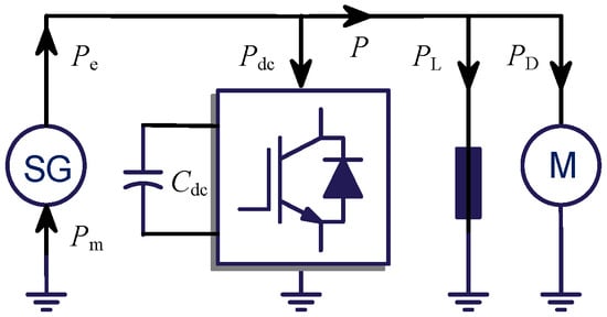
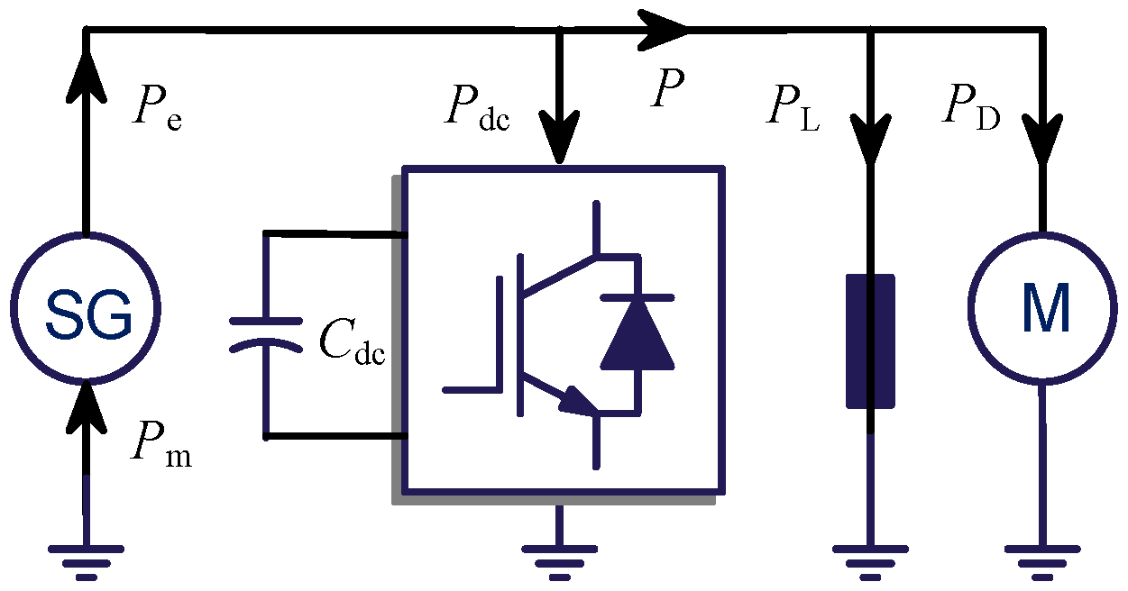
As depicted in Figure 1, the power system consists of a synchronous generator (SG) supplying electrical power Pe, frequency-dependent resistive loads consuming power PL, dynamic loads such as induction motors absorbing power PD, and grid-connected power converters drawing power Pdc. Notably, the power drawn by the PV inverter is equal to the deviation between the DC power supply and the power injected into the grid by the inverter.
Figure 1.
Simplified diagram of a typical power system (SG is a synchronous generator; M is a motor).
The SG establishes the classical electromechanical dynamics between active power imbalance and the grid frequency, as described by the established swing equation [17]:
where H and D denote the inertia time constant and damping coefficient, respectively. This equation provides the fundamental link between stored kinetic energy and the immediate frequency response to disturbances.
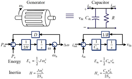
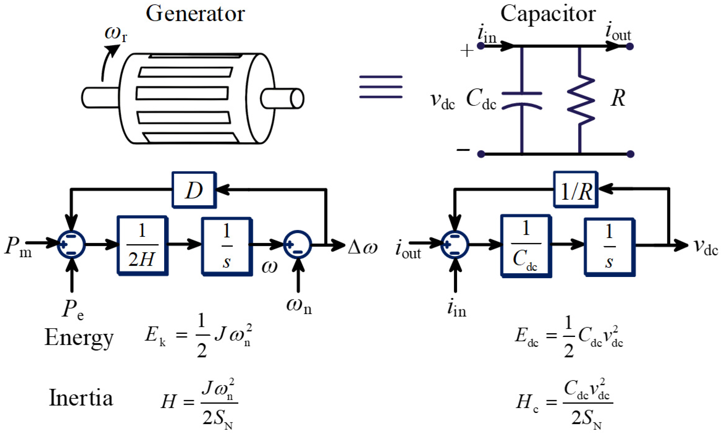
The DC-link capacitor Cdc in Figure 1 is capable of charging and discharging within short time scales. Thus, it can temporarily supply or absorb energy and therefore emulate an inertial response similar to a rotating mass, offering a fast-acting buffer during transients. This can further be explained in the following. The SG’s inertia constant is defined as H = Ek/(2SN) = ()/(2SN), where Ek is the stored kinetic energy, SN is the system rated power, J corresponds to the moment of inertia, and ωn indicates the rated angular frequency of the SG, respectively. As shown in Figure 2, the input current iin and output current iout associate with the DC-link capacitor, R is the parallel resistor, and its connection to the capacitor symbolically represents the damping circuit analogous to the rotor damping winding in an SG. As a result, the stored kinetic energy Edc and the equivalent inertia constant Hc for the DC-link capacitor can be expressed as
in which Cdc represents the DC-link capacitance, and vdc stands for the DC-link voltage. Both Edc and Hc scale quadratically with vdc. It can be mapped to an inertia constant Hc by normalizing the available energy to the system rated power SN. While the swing Equation in (1) is standard, the mapping of DC-link capacitor energy to an equivalent inertia constant Hc via (3) is a key modeling step that enables inertia quantification.
Figure 2.
Inertia mapping from a DC-link capacitor to a synchronous generator.
According to (1) and (3), the relationship between active power and capacitor voltage can be established as
where Pe, P denote the active power generated by the PV source and the output power of the grid-connected converter, respectively. Then, the power variation of the DC-link capacitor ΔPdc can be designated as
To realize the virtual inertia emulation, a FVDC strategy is incorporated. This control introduces a droop gain kf, which couples the grid angular frequency deviation (ω-ωn) with the DC-link voltage variation . The voltage can be regulated as
The power converter can inject a power variation ΔPdc to suppress frequency deviations through the incorporation of DC-link voltage dynamics. The core mechanism of this inertial response is derived by substituting the voltage–power relationship into the system model, thereby reformulating the power variation of the DC-link capacitor ΔPdc as
which demonstrates that the effective virtual inertia Hv provided by the inverter can be expressed as
which indicates that the dependence of the virtual inertia Hv on the system parameters can be made explicit through (9), limited by the DC-link capacitance Cdc, the DC-link voltage vdc, and the droop gain kf. When the FVDC strategy is enabled, the DC-link response may be represented as an additional inertia term Hv acting on the system, yielding an equivalent inertia Heq = H + Hv. However, excessively increasing kf or Cdc may introduce unfavorable dynamic interactions with the inner control loops and the grid, potentially degrading system damping or even leading to instability. Therefore, the virtual inertia provided by the DC-link capacitor cannot be arbitrarily amplified and must be carefully coordinated with the converter control dynamics. This observation motivates the following small-signal modeling and stability analysis, in which the influence of kf, Cdc, and vdc on the system’s eigenvalues and dynamic performance is systematically investigated.
3. Small-Signal Model of Power Systems
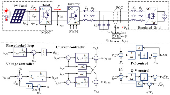
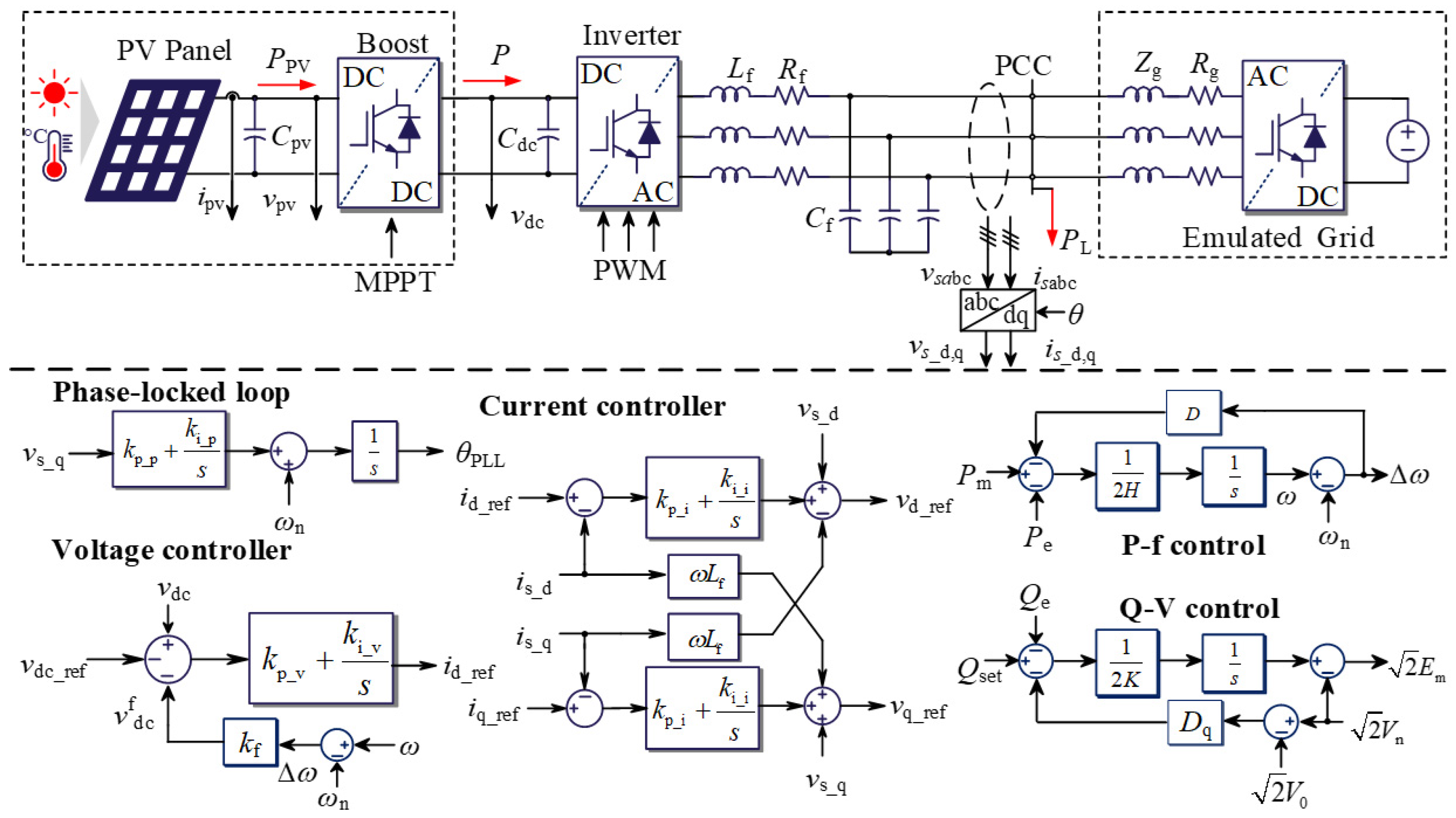
Figure 3 depicts the overall configuration of the grid-connected power converter operating under virtual inertia control. It consists of a PV source regulated through an MPPT-controlled DC/DC boost stage, a DC-link capacitor, and a grid-following converter delivering the power to the grid. The converter control architecture includes a PLL, inner current controllers, and an outer DC-link voltage controller that implements the FVDC strategy [18]. Specifically, the MPPT controller operates on a slower timescale compared to the DC-link voltage and frequency control loops. During fast frequency-support disturbances, the PV-side power PPV is assumed to remain approximately constant, and the required imbalance between the grid-side power and the PV input power is temporarily supplied by the DC-link capacitor.
Figure 3.
Overall system configuration of the grid-connected power converter with virtual inertia control. The arrows represent the power flow direction.
3.1. Phase-Locked Loop Modeling and Dynamics
The converter–grid phase synchronization is implemented using a PLL. Using the Park transformation, the measured three-phase voltages vsabc are converted into the synchronous rotating reference frame and their dq-axis components vs_d and vs_q are obtained. The synchronization objective is to align the rotating frame such that the q-axis component vs_q approaches zero in steady state, implying perfect phase alignment with the grid voltage vector [19]. In the frequency domain, the PLL’s estimated phase angle is given by
where the proportional and integral gains of the proportional–integral (PI) controller are denoted by kp_p and ki_p, respectively.
Employing the small-signal model of the PLL, which takes vs_q as its input, yields
The open-loop characteristic of the PLL is then obtained. Furthermore, the closed-loop transfer function from vs_q to the output phase θ is expressed as
in which Vm represents the magnitude of the three-phase voltage.
3.2. DC-Link Voltage Control and Linearization
The DC-link capacitor serves as the intermediate energy storage element between the DC source and the inverter. Its voltage vdc inherently reflects the instantaneous power imbalance between the power generated by the PV panel and the power delivered to the AC grid [20]. The control objective is to maintain vdc close to its nominal reference vdc_ref by dynamically adjusting the d-axis active current. A PI controller is implemented to regulate the active current reference as
Linearizing around the operating point yields the small signal that relates perturbations in the DC-link voltage, Δvdc, to the active current command deviation Δid:
in which id_ref denotes the d-axis reference current, kp_v and ki_v are the proportional and integral coefficients for the DC-link voltage PI controller, respectively, and vdc_ref represents the DC-link voltage reference with a droop relationship of the frequency deviations. This linearized model reveals the coupling between the dynamics of the DC-link voltage and active current, which plays a crucial role in shaping the virtual inertia response under FVDC.
3.3. Current Control Loop and Linearization
The inner loop of the current control is responsible for fast regulation of the converter output current, ensuring accurate following of the reference signals generated by the DC-link voltage controller. The grid-connected converter current dynamics in the synchronous dq-axis frame can be expressed as
where Lf and Rf denote the filter inductance and resistance, respectively, and is_d and is_q denote the dq-axis components corresponding to the output current, respectively. To achieve the decoupled control of the active and reactive current components, the feedforward compensation term ±ωLf is_d,q is typically introduced, resulting in a linearized control law for the converter reference voltage.
Considering that the converter-side filter dynamics characterized by Lf and Rf may influence the system behavior, especially under weak-grid conditions, the d-axis current dynamics are described as
in which kp_i and ki_i are the proportional and integral coefficients for the current PI controller, respectively. When the current loop bandwidth is sufficiently higher than that of the outer loops, the approximation is_d ≈ id_ref can be adopted for the analytical insight.
3.4. Power Dynamics and Linearization
In steady state, the electrical power Pe delivered by the grid-connected inverter in the synchronous reference frame can be expressed as
where the d-axis grid voltage component remains constant, i.e., vs_d = Vm. The small-signal perturbation of the active power can be linearized as
thus, the dynamic of is_d is governed by the combined action of the outer voltage control and the inner current loop. As noted in Section 3.3, the current control loop operates sufficiently fast to be approximated as an ideal current source. To capture the grid-side frequency dynamics, a small-signal representation of the VSG is introduced, and the linearized swing equation governing the grid frequency is written as
where ωg is the grid angular frequency.
The small-signal model developed in this section unifies the DC-link dynamics, current control, PLL, and VSG behavior into a single stability analysis framework. This section provides a explicit derivation of the virtual inertia coefficient Hv as a function of kf, Cdc, and vdc, which forms the basis for the stability margin analysis in Section 4.
4. Stability Margin Analysis of the Model
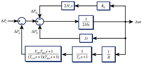
To analyze the FVDC strategy, the DC-link dynamics and converter control are embedded into a system-level linearized frequency regulation model. This model integrates the adopted converter control with the conventional SG dynamics, including the speed governor time constant TG, turbine coefficients FHP, reheater time constant TRH, inlet volume time constant TCH, and the frequency droop coefficient R [21]. The relevant SG parameters are listed in Table 1.
Table 1.
Parameters of a synchronous generator (SG).
According to Figure 4, the virtual inertia is inserted as an additional feedback branch that modifies the system mechanical response. The relationship between the load disturbance ΔPL and the frequency deviation Δω can be expressed through the following transfer function:
It is important to emphasize that the linearized frequency control framework is valid only for small-signal analysis, in which the frequency deviation f − fn remains small, ensuring that the linear approximation around the nominal operating point is accurate.
Figure 4.
Block diagram of the frequency control framework with virtual inertia.
The eigenvalue loci of (23) for different equivalent inertia constants are illustrated in Figure 5. The pole-zero map reveals important trends:
- (1)
- As the equivalent inertia H increases, the dominant conjugate pole pair shifts toward the imaginary axis, indicating a reduced damping ratio.
- (2)
- The real poles P3 and P4, corresponding to the dynamics of the DC-link voltage, move closer to the zeros Z2 and Z3 introduced by the outer-loop compensator.
Figure 5.
Eigenvalue loci with the inertia variation in H.
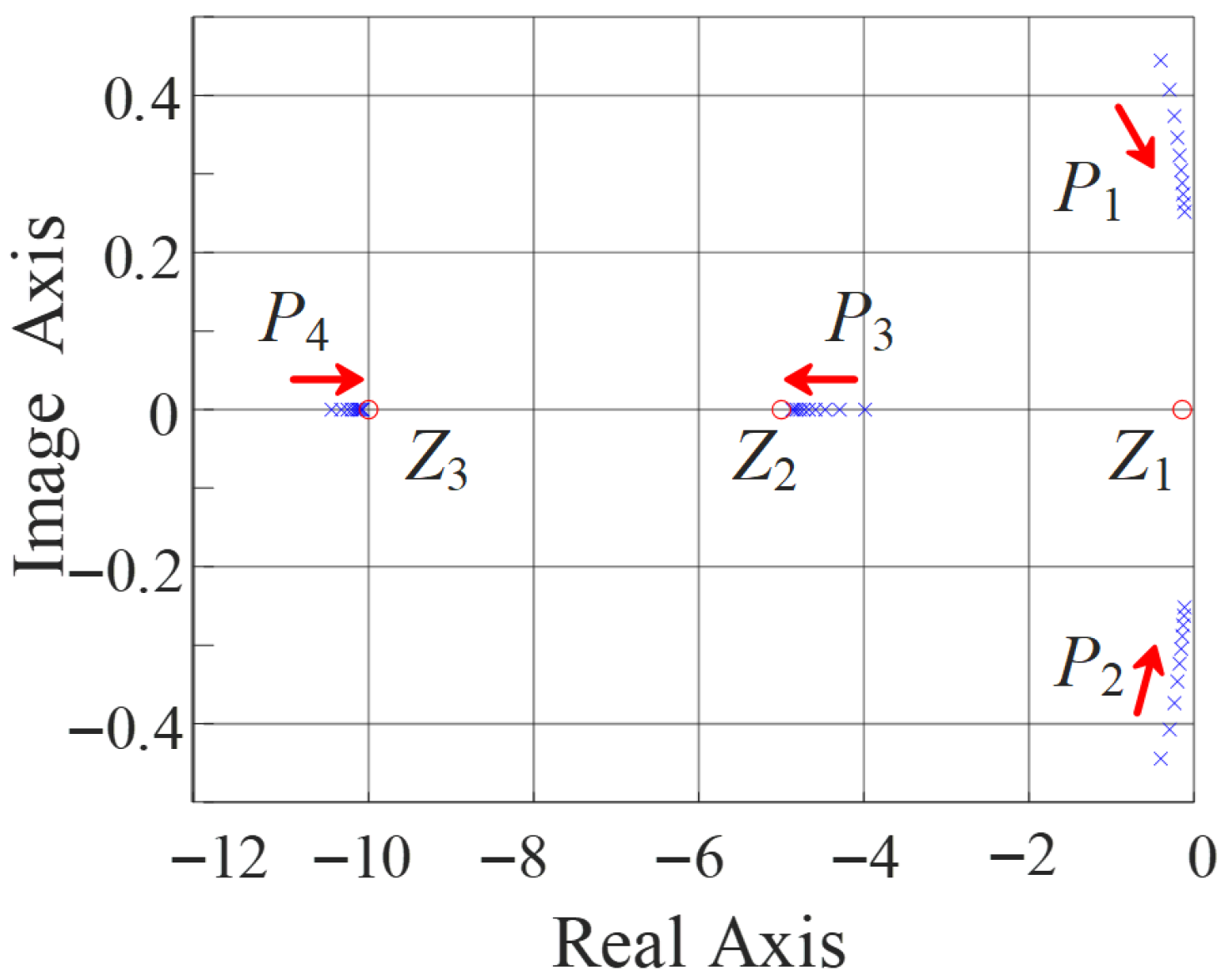
These results confirm that the DC-link-based virtual inertia effectively enhances the system’s frequency stability while introducing a fundamental trade-off between damping and recovery dynamics.
Seen from a control design perspective, appropriate coordination between the droop gain kf, the DC-link capacitance Cdc and the DC-link voltage vdc is essential. These parameters jointly determine the frequency response, virtual inertia emulation, and the dynamics of the DC-link voltage control loop. To assess the impact of the system parameters in detail, the closed-loop small-signal model is derived by linking the converter dynamics with the VSG-based grid model (see Figure 3). The corresponding small-signal active power at the point of common coupling (PCC) can be expressed as
Substituting the DC-link voltage dynamics of (9) and the VSG swing equation of (22) into (24) and incorporating the outer voltage control loop yields the closed-loop transfer function that relates a load perturbation ΔPL to the resulting frequency deviation Δωg:
where N(s) and D(s) represent the numerator and denominator polynomials.
Analysis of the characteristic equation D(s) = 0 enables systematic assessment of the eigenvalue migration, system damping, and robustness under various operating conditions. This provides a quantitative foundation for selecting appropriate combinations of kf, Cdc and vdc that achieve sufficient inertia support without destabilizing the voltage regulation loop. To explore the findings derived from the characteristic equation and to quantify how the DC-link parameters influence stability in low-inertia system, a 50 kW grid-connected PV converter is selected and the inertia constant is adaptive. The system parameters used for the analysis and subsequent case studies are summarized in Table 2. These parameters are substituted into the closed-loop characteristic equation D(s) = 0 to compute root trajectories under varying DC-link voltages and capacitances, enabling a direct assessment of how the parameter design choices shape the stability boundary. Two scenarios are considered:
- (1)
- Scenario 1: The DC-link capacitance is fixed at Cdc = 2 mF, while the DC-link voltage is varied among values of 1000 V, 1500 V, 2000 V, 2500 V. The corresponding eigenvalue loci are shown in Figure 6.
- (2)
- Scenario 2: Under the same inertia condition, the DC-link voltage is fixed at vdc = 1500 V, while the capacitance is varied among values of 2 mF, 4 mF, 6 mF, and 8 mF. Figure 7 illustrates the corresponding trajectories and stability boundary.
Table 2.
Parameters of the system for case study.
Figure 6.
Eigenvalue loci and stability boundaries: (a) kfmax = 25 at vdc = 1000 V, (b) kfmax = 15.4 at vdc = 1500 V, (c) kfmax = 10.9 at vdc = 2000 V and (d) kfmax = 8.1 at vdc = 2500 V, where the DC-link capacitance is fixed (Cdc = 2 mF).
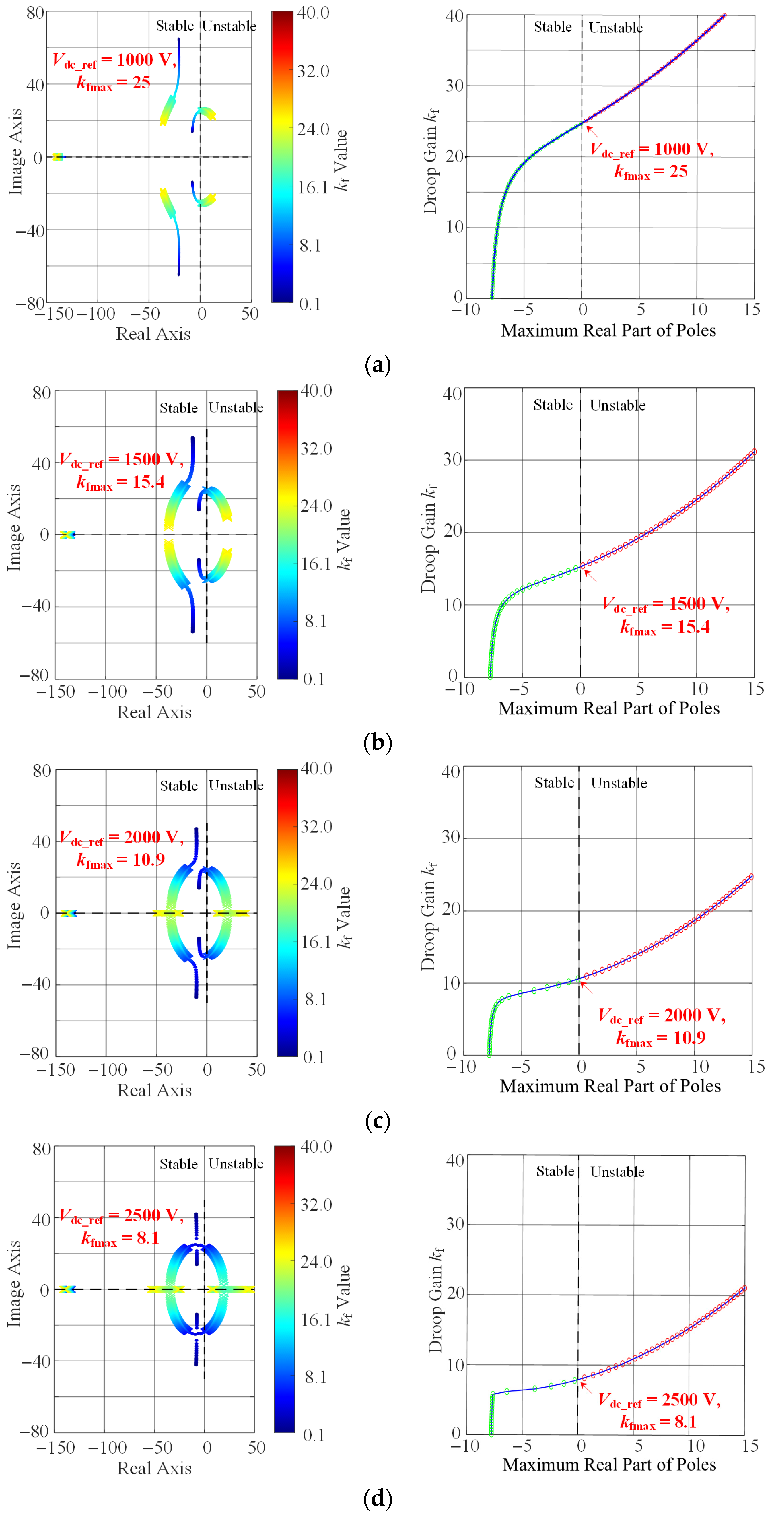
Figure 7.
Eigenvalue loci and stability boundaries: (a) kfmax = 15.4 at Cdc = 2 mF, (b) kfmax = 11.6 at Cdc = 4 mF, (c) kfmax = 9.1 at Cdc = 6 mF, and (d) kfmax = 7.5 at Cdc = 8 mF, where the DC-link voltage is fixed (vdc = 1500 V).
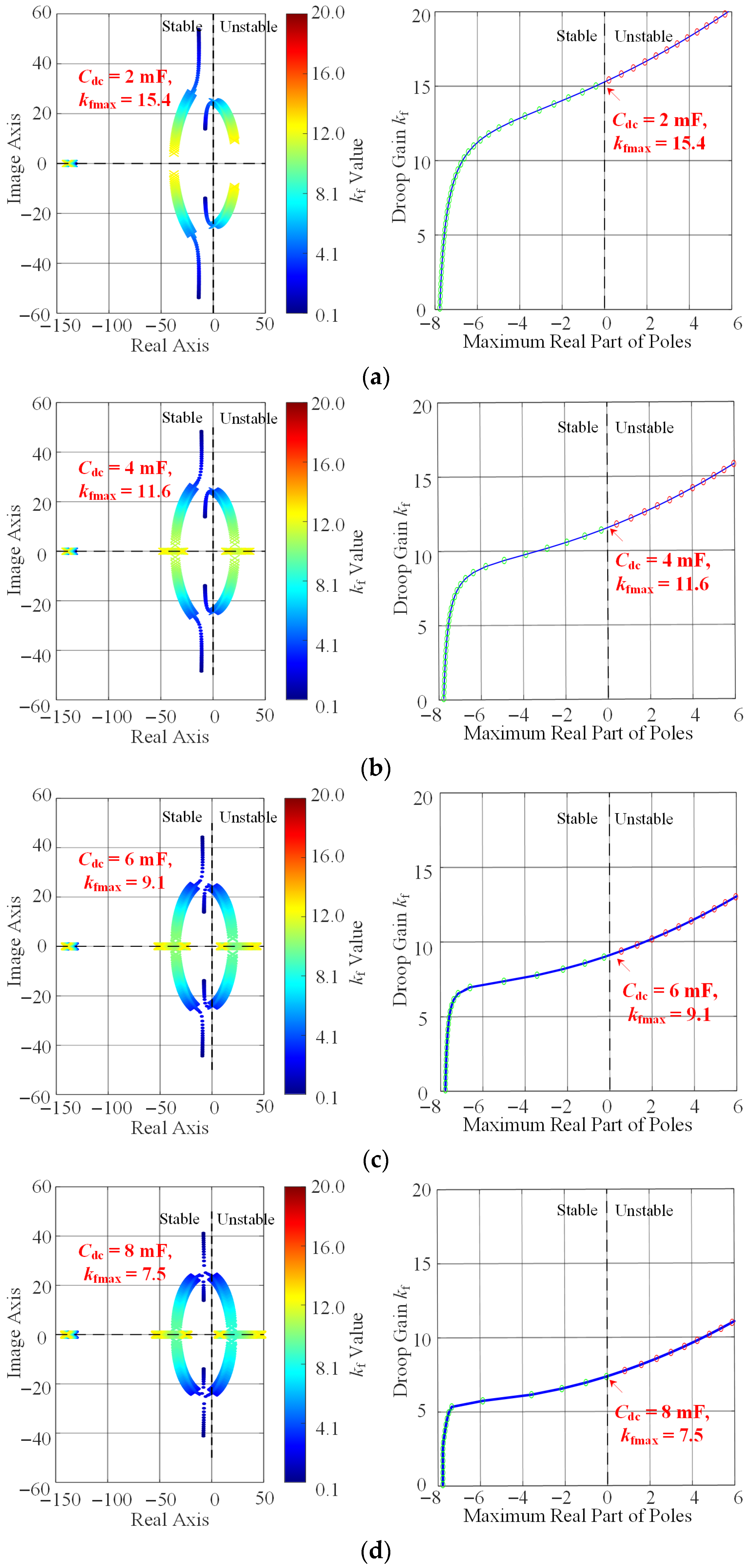
Figure 6 demonstrates that the variation trend of the characteristic root of kf aligns with the previous analysis. However, increasing the DC-link voltage significantly affects the stability boundary of kf. As vdc increases from 1000 V to 2500 V, the maximum stability droop gain kfmax reduces from 25 to 8.1. This behavior shows that higher DC-link voltage levels strengthen stronger coupling between DC-side energy fluctuations and AC-side power modulation, thereby reducing the phase margin and narrowing the stability boundary. A comparison of the corresponding virtual inertia should be carried out using (9). A detailed evaluation will be presented in the next subsection.
Furthermore, as observed in Figure 7, increasing the capacitor value causes a reduction in the stable operating range of the droop gain. When Cdc is increased from 2 mF to 8 mF, the maximum stable droop gain kfmax decreases from approximately 15.4 to 7.5. Although a larger capacitor enhances the energy buffering capability and increases the attainable virtual inertia intuitively, it simultaneously slows the DC-link voltage dynamics, thereby reducing damping and the stability margin.
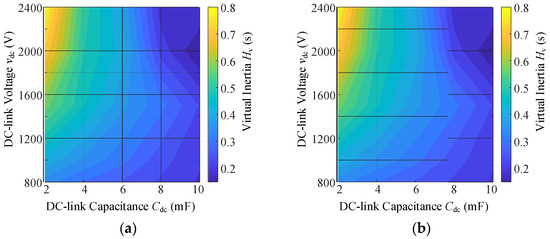
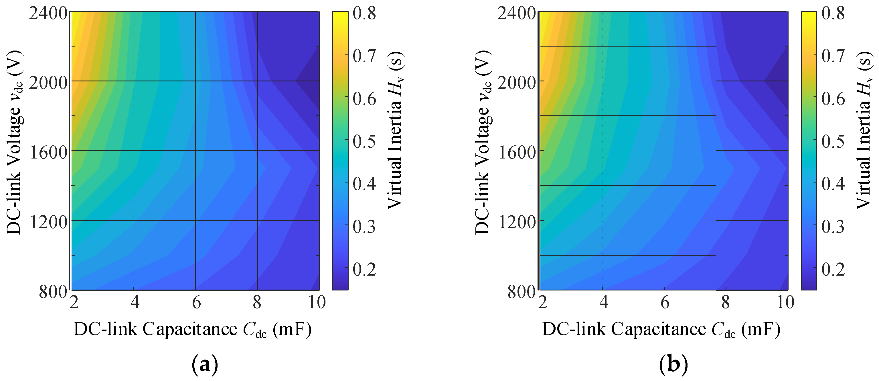
Using the virtual inertia derived from (9) contributed by the DC-link capacitor, the maximum usable virtual inertia under different DC-link voltage levels and the capacitance can be determined, while the corresponding stability-limited droop gain kfmax can be evaluated, as depicted in Figure 8. As illustrated in Figure 8, increasing the DC-link voltage effectively enhances the maximum virtual inertia that can be delivered to the grid. However, enlarging the capacitance significantly narrows the stability boundary. Consequently, despite the larger stored energy, the inertia that can actually be utilized for frequency support is reduced.
Figure 8.
Contours of virtual inertia capability and stability boundary: (a) the maximum achievable virtual inertia contour and (b) the stability boundary contour.
With the above two scenarios, it has been revealed that increasing both the DC-link capacitance and the voltage level of the capacitor tends to reduce the stable boundary of the control system. This further highlights:
- (1)
- A larger Cdc and a higher vdc enhance the stored energy obtainable for virtual inertia.
- (2)
- Both the DC-link capacitance and the voltage intensify the coupling dynamics and decrease the stability margins.
- (3)
- The DC-link capacitance reduces the maximum usable virtual inertia, while the voltage increases the maximum available virtual inertia.
In practical engineering applications, the DC-link voltage vdc should be elevated as high as permissible within the limits of device insulation and economic feasibility, so as to expand the upper bound of achievable virtual inertia. Regarding the design of DC-link capacitance Cdc, simply pursuing large energy storage capacity is not advisable, instead, its value should be determined holistically based on both the required energy for frequency support and the desired dynamics.
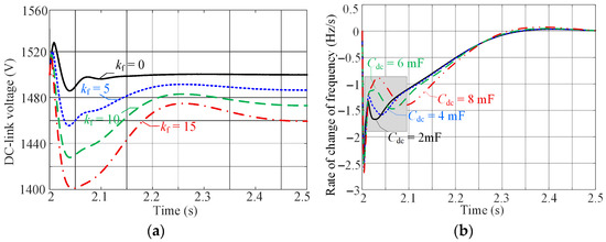
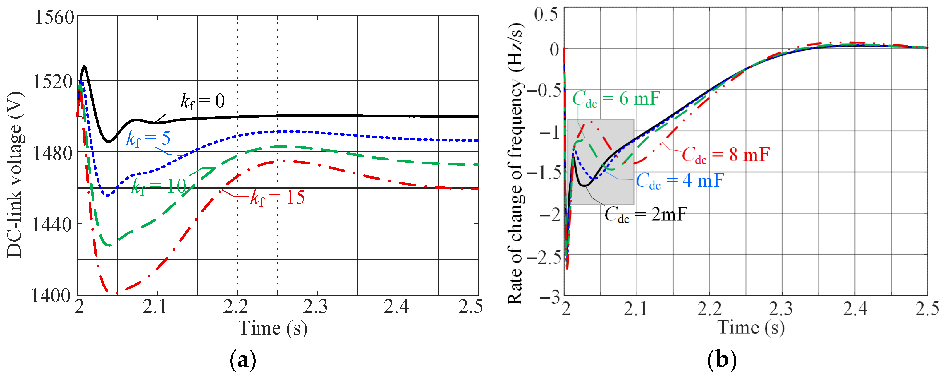
It should be noted that the linearized model is valid only around the nominal operating point and may not fully capture nonlinear effects under large-signal conditions or sustained disturbances. To address this limitation, simulations under the same inertia condition, with the disturbance increased by 50% (25 kW) are shown in Figure 9. The variation in kf and Cdc is again examined. The simulations confirm that even under large disturbances, our main findings remain valid.
Figure 9.
Simulations of the grid-connected system under 50% load disturbances: (a) inverter DC-link voltage when kf changes and (b) RoCoF when Cdc changes.
Notably, in practice, the converter current saturation, DC-link voltage constraints, and controller anti-windup mechanisms will potentially limit the maximum usable virtual inertia. It should be noted that the FVDC increases active power injection in proportion to the frequency deviations. Under large disturbances, the current reference generated by the outer loops may exceed converter limits, resulting in the saturation of the current controller and a reduced effective inertial response. From (9), it is further revealed that the inertia response is fundamentally supported by DC-link energy extraction, which causes deviations of vdc. However, the maximum virtual inertia is bounded by the allowable DC voltage. Once the voltage reaches its limit, the FVDC loop cannot further release energy, and the inertia response is clipped. Therefore, when saturation occurs, anti-windup protection in the DC voltage controller and power reference generation becomes essential. Nevertheless, the above analysis confirms that it is important to coordinate the inertia synthesis and the DC-link design for stable operation of grid-connected PV systems.
5. Experimental Verification
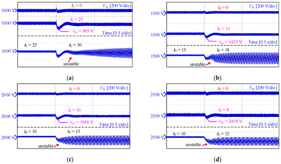
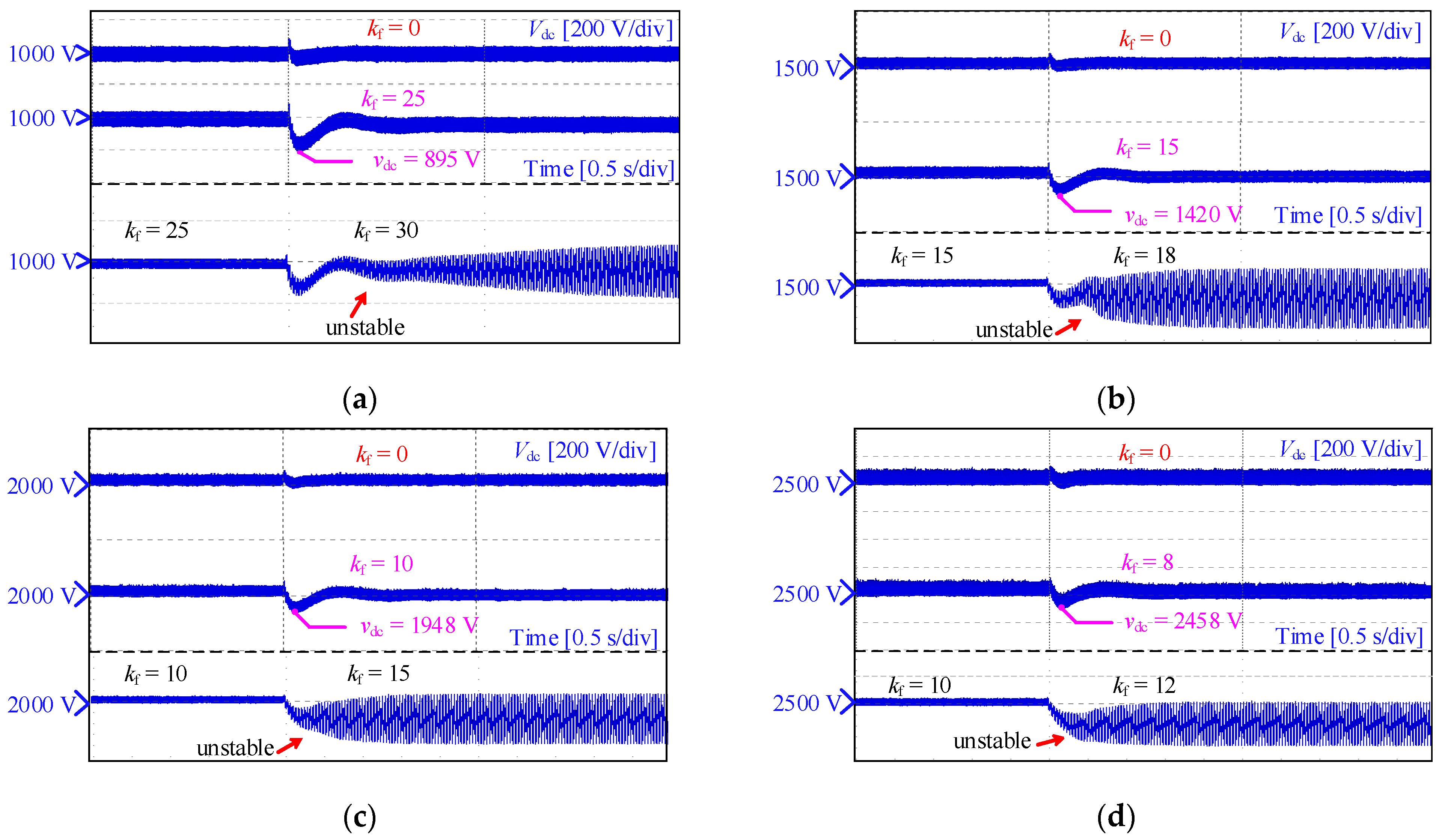
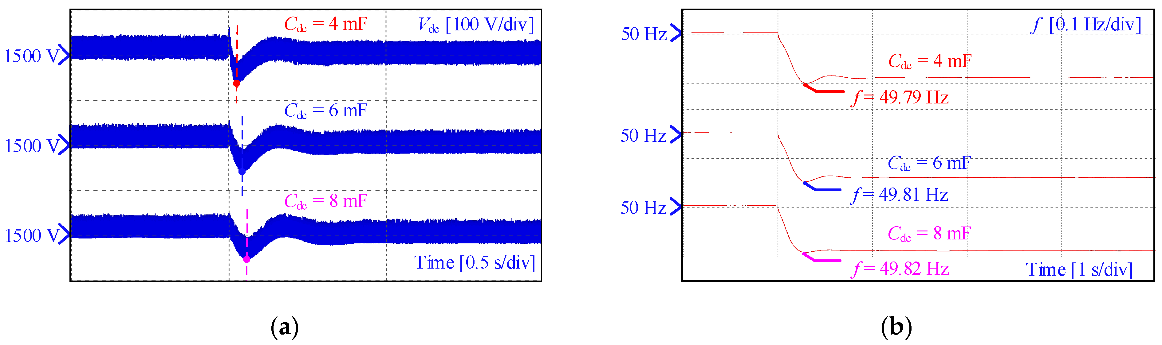
A hardware-in-the-loop (HIL) experimental setup was developed for validation, integrating a dedicated real-time simulation platform with an MT-8020 simulator for electromagnetic transient simulation. This setup is used to assess the stability boundaries from the eigenvalue analysis and Table 2 shows the corresponding parameters. The experiment focused on two scenarios: varying the DC-link voltage vdc and the droop gain with a fixed capacitance and varying the DC-link capacitance Cdc under a fixed voltage and droop gain. The experimental test results are shown in Figure 10, Figure 11 and Figure 12.
Figure 10.
Experimental results of the grid-connected system when kf changes: (a) vdc = 1000 V, (b) vdc = 1500 V, (c) vdc = 2000 V and (d) vdc = 2500 V.
Figure 11.
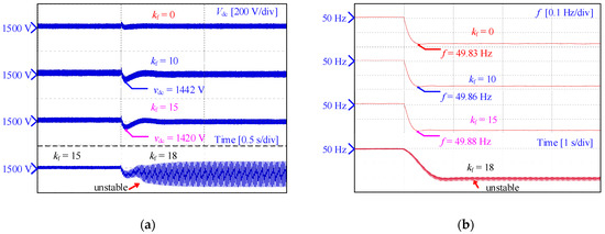
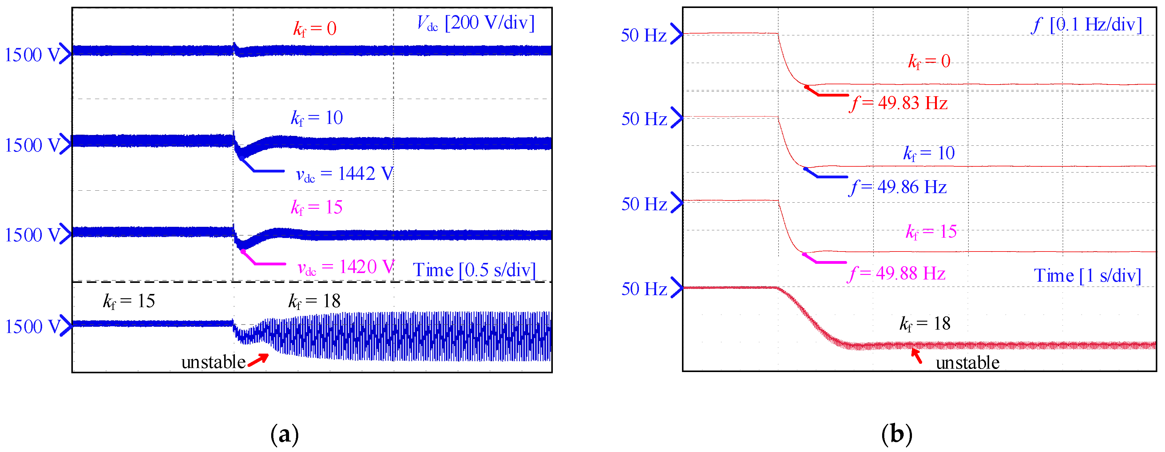
Experimental results of the grid-connected system when kf = 0, 10, 15 and 18: (a) inverter DC-link voltage and (b) the grid frequency f.
Figure 12.
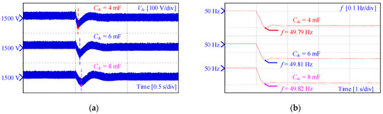
Experimental results of the grid-connected system when Cdc = 4 mF, 6 mF and 8 mF: (a) inverter DC-link voltage and (b) the grid frequency f.
As illustrated in Figure 10, the DC-link capacitance is fixed at Cdc = 2 mF, while the DC-link voltage is varied among values of 1000 V, 1500 V, 2000 V, and 2500 V. As vdc increases, the maximum kf ensuring stable operation decreases noticeably. For each voltage level, the results clearly distinguish the stable and unstable responses of the DC-link voltage. This behavior agrees with the eigenvalue analysis shown in Figure 6, demonstrating that a higher DC-link voltage intensifies the coupling between DC-side energy variations and AC-side power. Consequently, the system responses to the droop gain adjustment become more sensitive, and the stability boundary of kf is significantly reduced. These results experimentally validate the theoretical conclusion that increasing vdc narrows the stable boundary of the inertia-emulating droop law control loop.
The system response to a 10% load (5 kW) step is tested for kf = 0, 10, 15 and 18 and the results are depicted in Figure 11. As shown in Figure 11b, with kf = 0, the frequency nadir drops to 49.83 Hz and the RoCoF reaches 1.44 Hz/s. When kf = 15, the frequency–voltage droop controller is activated, leading the DC-link capacitor to discharge active power to stabilize the grid frequency. In such a case, the frequency nadir increases to 49.88 Hz, the RoCoF is reduced to 1.23 Hz/s, and the voltage dip becomes 1420 V. The results in Figure 11 demonstrate that the DC-link capacitor contributes to both frequency regulation and inertia provision. If a higher level of inertia is needed, the corresponding coefficient should be raised. However, this may jeopardize the control stability, as aforementioned.
Similarly, the DC-link voltage is maintained at vdc = 1500 V, while the capacitance is varied among values of 2 mF, 4 mF, 6 mF, and 8 mF. The corresponding DC-link voltage and frequency responses are shown in Figure 12. It is demonstrated in Figure 12 that a larger Cdc reduces the transient deviation of the DC-link voltage while simultaneously mitigating the frequency nadir, and leads to a reduction in the RoCoF from 1.42 Hz/s to 1.12 Hz/s. It confirms its role in strengthening system frequency response under various operating conditions. However, the improvement is not strictly linear. When Cdc becomes excessively large, the dynamics of the inner voltage control loops are slow, leading to a degraded transient performance. Conversely, if Cdc is small, the energy buffering capability is insufficient, limiting the available inertia.
Overall, the experimental observations are highly consistent with the closed-loop characteristic analysis. The relationship between these parameters and the stability boundary underscores a critical design constraint for virtual inertia emulation in grid-connected converters. Based on these findings, a practical guideline can be obtained for a given system that the DC-link voltage and capacitance should be co-designed to achieve a target virtual inertia while respecting the droop gain stability limits derived from small-signal analysis. This approach ensures both effective frequency support and robust converter operation.
6. Discussion
This section synthesizes the analytical derivations and experimental results to highlight the key findings and original contributions of this study. A key contribution of this work is the quantitative characterization of the virtual inertia that can be synthesized from the DC-link capacitor under stability constraints. Unlike existing studies that mainly demonstrate the qualitative capability of DC-link energy to support frequency dynamics, the adopted analytical framework relates the achievable virtual inertia to the DC-link voltage level, capacitance value, and frequency–voltage droop gain. The results show that the maximum usable virtual inertia is not solely limited by the stored energy, but fundamentally constrained by closed-loop stability.
A trade-off is identified through the small-signal and eigenvalue analysis. Increasing the DC-link voltage enlarges the available energy buffer and thus enables higher virtual inertia contribution. However, it simultaneously narrows the admissible stability margin of the droop gain, leading to reduced damping and increased sensitivity to control parameter variations. This trade-off, which cannot be directly inferred from energy-based considerations alone, provides an important insight for inertia-oriented controller design in low-inertia grids.
The experimental results are specifically designed to validate these analytically predicted limits and trends. The HIL experimental tests confirm that, within the derived stability boundaries, the FVDC-based VSG control effectively suppresses the RoCoF and improves the frequency nadir under load disturbances. Moreover, the results demonstrate that exceeding the stability-constrained droop gain results in degraded damping performance, thereby experimentally corroborating the theoretical stability analysis.
It should be noted that the present study is confined to a single-inverter configuration and primarily addresses dynamic performance. Future work will extend the analysis to multi-inverter systems, where interactions among converters and grid impedance may introduce additional coupled dynamics. Moreover, extending the validation to multiple ratings and a wide SCR range is an important direction, which will be the future work. In addition, economic aspects including DC-link capacitor sizing and cost–performance trade-offs will be investigated to evaluate the practical feasibility of the proposed approach.
7. Conclusions
This paper has explored the capability of DC-link capacitors to supply synthesized inertia in grid-connected PV converters under the FVDC-based VSG control framework. An analytical formulation has been developed, establishing explicit relationships among the DC-link voltage, capacitance, and droop gain (stability). The theoretical analysis results reveal a fundamental trade-off that increasing the DC-link voltage enhances the stored energy and thereby the maximum obtainable virtual inertia, while simultaneously narrowing the stability margin of the droop gain. Experimental tests have validated the analytical findings, demonstrating that the FVDC strategy effectively suppresses the RoCoF and improves the frequency nadir under disturbances, while also highlighting the sensitivity of the dynamic response to DC-link and control-loop interactions. Furthermore, the accurately quantified virtual inertia and stability boundaries in this paper provide a useful theoretical and experimental basis for parameter design and optimization of inertia support in low-inertia grids, contributing to more robust and stable power systems.
Author Contributions
Conceptualization, Q.H. and Y.Y.; methodology, Q.H.; validation, Q.H. and L.D.; formal analysis, Q.H.; investigation, Q.H.; writing—original draft preparation, Q.H. and L.D.; writing—review and editing, Q.P. and Y.Y.; supervision, Y.Y. All authors have read and agreed to the published version of the manuscript.
Funding
This research received no external funding.
Data Availability Statement
The results are either experimental tests or simulation results and included in the paper. No new data were created in this study.
Conflicts of Interest
The authors declare no conflict of interest.
References
- Blaabjerg, F.; Teodorescu, R.; Liserre, M.; Timbus, A.V. Overview of Control and Grid Synchronization for Distributed Power Generation Systems. IEEE Trans. Ind. Electron. 2006, 53, 1398–1409. [Google Scholar] [CrossRef] [Scilit]
- Azizi, A.; Akhbari, M.; Danyali, S.; Tohidinejad, Z.; Shirkhani, M. A review on topology and control strategies of high-power inverters in large-scale photovoltaic power plants. Heliyon 2025, 11, e42334. [Google Scholar] [CrossRef] [Scilit] [PubMed]
- Peng, Q.; Sangwongwanich, A.; Yang, Y.; Blaabjerg, F. Grid-friendly power control for smart photovoltaic systems. Sol. Energy 2020, 210, 115–127. [Google Scholar] [CrossRef] [Scilit]
- Valikhany, M.; Astero, P.; Lehtonen, M.; Peltoniemi, P. A review on the suitability of virtual inertia strategies for the next generation of low-inertia power systems. E-Prime-Adv. Electr. Eng. Electron. Energy 2025, 14, 101131. [Google Scholar] [CrossRef] [Scilit]
- Rathnayake, D.B.; Razzaghi, R.; Bahrani, B. Generalized Virtual Synchronous Generator Control Design for Renewable Power Systems. IEEE Trans. Sustain. Energy 2022, 13, 1021–1036. [Google Scholar] [CrossRef] [Scilit]
- Rajan, R.; Fernandez, F.M.; Yang, Y. Primary frequency control techniques for large-scale PV-integrated power systems: A review. Renew. Sustain. Energy Rev. 2021, 144, 110998. [Google Scholar] [CrossRef] [Scilit]
- Fang, J.; Li, H.; Tang, Y.; Blaabjerg, F. Distributed Power System Virtual Inertia Implemented by Grid-Connected Power Converters. IEEE Trans. Power Electron. 2018, 33, 8488–8499. [Google Scholar] [CrossRef] [Scilit]
- Peng, Q.; Yang, Y.; Liu, T.; Blaabjerg, F. Coordination of virtual inertia control and frequency damping in PV systems for optimal frequency support. CPSS Trans. Power Electron. Appl. 2020, 5, 305–316. [Google Scholar] [CrossRef] [Scilit]
- Pulgar-Painemal, H.; Wang, Y.; Silva-Saravia, H. On Inertia Distribution, Inter-Area Oscillations and Location of Electronically-Interfaced Resources. IEEE Trans. Power Syst. 2018, 33, 995–1003. [Google Scholar] [CrossRef] [Scilit]
- Mahmood, Z.I.; Cui, H.; She, B. Evaluating the equivalent inertia of grid-following and grid-forming inverter-based resources. IEEE Trans. Energy Convers. 2024, 40, 1984–1996. [Google Scholar] [CrossRef] [Scilit]
- Peng, Q.; Fang, J.; Yang, Y.; Liu, T.; Blaabjerg, F. Maximum Virtual Inertia From DC-Link Capacitors Considering System Stability at Voltage Control Timescale. IEEE J. Emerg. Sel. Top. Circuits Syst. 2021, 11, 79–89. [Google Scholar] [CrossRef] [Scilit]
- Su, X.; Wang, M.; Liu, Y. A Virtual-Capacitor-Based Inertia Enhancement Method for Switching Converters in DC Microgrids. IEEE Trans. Ind. Electron. 2026, 73, 1481–1486. [Google Scholar] [CrossRef] [Scilit]
- Guo, K.; Fang, J.; Tang, Y. Autonomous DC-Link Voltage Restoration for Grid-Connected Power Converters Providing Virtual Inertia. In 2018 IEEE Energy Conversion Congress and Exposition (ECCE); IEEE: New York, NY, USA, 2018; pp. 6387–6391. [Google Scholar]
- Fan, Z.; Zhang, J.; Zheng, T. Control Method for Coordinated Power Frequency Modulation and DC Voltage Recovery in Grid-Connected Photovoltaic System. In 2023 26th International Conference on Electrical Machines and Systems (ICEMS); Curran Associates, Inc.: Red Hook, NY, USA, 2023; pp. 3964–3968. [Google Scholar]
- Zhang, Z.; Fang, J.; Dong, C.; Jin, C.; Tang, Y. Enhanced Grid Frequency and DC-Link Voltage Regulation in Hybrid AC/DC Microgrids Through Bidirectional Virtual Inertia Support. IEEE Trans. Ind. Electron. 2023, 70, 6931–6940. [Google Scholar] [CrossRef] [Scilit]
- Haddadi, M.; Gorji, S.A.; Yu, S.S. An Overview of Inertia Emulation Strategies for DC Microgrids: Stability Analysis and AC Microgrid Analogies. IEEE Open J. Ind. Electron. Soc. 2025, 6, 491–521. [Google Scholar] [CrossRef] [Scilit]
- Yuan, H.; Yuan, X.; Hu, J. Modeling of Grid-Connected VSCs for Power System Small-Signal Stability Analysis in DC-Link Voltage Control Timescale. IEEE Trans. Power Syst. 2017, 32, 3981–3991. [Google Scholar] [CrossRef] [Scilit]
- Boscaino, V.; Ditta, V.; Marsala, G. Grid-connected photovoltaic inverters: Grid codes, topologies and control techniques. Renew. Sustain. Energy Rev. 2024, 189, 113903–113924. [Google Scholar] [CrossRef] [Scilit]
- Fang, J.; Zhang, R.; Li, H.; Tang, Y. Frequency Derivative-Based Inertia Enhancement by Grid-Connected Power Converters with a Frequency-Locked-Loop. IEEE Trans. Smart Grid 2019, 10, 4918–4927. [Google Scholar] [CrossRef] [Scilit]
- Li, D.; Zhu, Q.; Lin, S.; Bian, X.Y. A Self-Adaptive Inertia and Damping Combination Control of VSG to Support Frequency Stability. IEEE Trans. Energy Convers. 2017, 32, 397–398. [Google Scholar] [CrossRef] [Scilit]
- Fang, J.; Li, H.; Tang, Y.; Blaabjerg, F. On the Inertia of Future More-Electronics Power Systems. IEEE J. Emerg. Sel. Top. Power Electron. 2019, 7, 2130–2146. [Google Scholar] [CrossRef] [Scilit]

Disclaimer/Publisher’s Note: The statements, opinions and data contained in all publications are solely those of the individual author(s) and contributor(s) and not of MDPI and/or the editor(s). MDPI and/or the editor(s) disclaim responsibility for any injury to people or property resulting from any ideas, methods, instructions or products referred to in the content. |
© 2026 by the authors. Licensee MDPI, Basel, Switzerland. This article is an open access article distributed under the terms and conditions of the Creative Commons Attribution (CC BY) license.