


Abstract
Intentional high-power electromagnetic (EM) interference poses a serious threat to sensitive electronic systems and often manifests as ultra-wideband (UWB) sub- and nanosecond pulses. Metallic shielding enclosures with technological apertures are commonly used for protection; however, apertures enable electromagnetic coupling into the enclosure and limit shielding performance. While most existing studies focus on transient disturbances with durations exceeding the enclosure transit time, this work addresses an ultrashort high-power subnanosecond UWB plane-wave pulse whose duration is significantly shorter than the enclosure transit time, a regime that remains insufficiently explored. A time-domain numerical analysis is performed for a low-profile rectangular metallic enclosure with a front-wall aperture, focusing on internal EM field evolution, internal pulse formation, and polarization-dependent shielding effectiveness. Three-dimensional full-wave simulations were carried out using CST Microwave Studio over a 90 ns observation window. The results show that the incident pulse excites primary subnanosecond EM waves inside the enclosure, which subsequently generate secondary waves through multiple reflections from the enclosure walls. Their interaction produces complex, long-lasting, time-varying internal field patterns. Although attenuated, the resulting internal subnanosecond pulses repeatedly traverse the enclosure interior, forming a pulse train-like sequence that may pose a cumulative electromagnetic threat to internal electronics. A key contribution of this work is the quantification of time-dependent local shielding effectiveness for both electric and magnetic fields, derived directly from the internal pulse train-like series obtained in the time domain. The concept of local, time-dependent shielding effectiveness provides physical insight that cannot be obtained from a single globally averaged SE value. In the case of ultrashort electromagnetic pulse excitation, the internal field response of an enclosure is strongly non-stationary and highly non-uniform in space, with local field maxima occurring at specific times and locations despite good average shielding performance. Time-dependent local SE enables identification of worst-case temporal conditions, repeated high-amplitude internal exposures, and critical regions inside the enclosure where shielding is significantly weaker than suggested by global metrics. Therefore, while conventional SE remains useful as a summary measurand, local time-dependent SE is essential for assessing the actual electromagnetic risk to sensitive electronics under ultrashort pulse disturbances. In addition, a global shielding effectiveness metric mapped over selected enclosure cross-sections is introduced to enable rapid visual assessment of shielding performance. The analysis demonstrates a strong dependence of internal wave propagation, internal pulse formation, and both local and global shielding effectiveness on the polarization of the incident subnanosecond EM pulse. These findings provide new physical insight into aperture coupling and shielding behavior in the ultrashort-pulse regime and offer practical guidance for the assessment and design of compact shielding enclosures exposed to high-power UWB EM threats.
1. Introduction
Intentional high-power electromagnetic (EM) interference represents a growing threat to sensitive electronic infrastructure. Such attacks are no longer limited to military systems but increasingly affect industrial facilities, law enforcement, transportation, emergency services, consumer electronics, and financial systems. The literature reports a steady increase in the use of relatively accessible high-power EM pulse sources for intentional interference and attack scenarios [1,2]. This trend necessitates intensified research efforts aimed at developing effective electromagnetic protection and mitigation strategies [1,2,3,4,5,6,7].
Metallic shielding enclosures are widely used to protect electronic equipment and systems vulnerable to electromagnetic disturbances [2,4,5,6]. Large-scale enclosures are employed to safeguard complex electronic installations in industry, government, military, and financial institutions. In parallel, growing attention has been directed toward compact shielding enclosures for small electronic devices such as laptops, tablets, smartphones, identification cards, and vehicle access keys [3].
Fully closed metallic enclosures provide near-ideal electromagnetic shielding but are impractical in real applications due to the need for signal transmission, power supply, ventilation, and thermal management. These functional requirements necessitate the presence of technological openings (apertures) in enclosure walls. The introduction of apertures fundamentally degrades shielding performance by enabling electromagnetic coupling into the enclosure interior. Consequently, the level of protection afforded to enclosed electronics depends on both the characteristics of the penetrating EM disturbance and the susceptibility of the protected devices to its temporal, spatial, and spectral properties.
It is widely recognized that ultrashort, high-intensity EM pulses—characterized by extremely high electric field amplitudes and correspondingly high peak power but relatively low total energy—are particularly effective in intentional EM interference scenarios. In contrast, attacks based on high total EM energy delivered over longer durations are generally less efficient and more resource-intensive. When high-energy EM pulses interact with enclosures containing small apertures, the transmitted energy is typically strongly attenuated, resulting in limited thermal effects inside the enclosure. By comparison, ultrashort sub- and nanosecond pulses entering through apertures can induce large transient voltages and currents in electronic circuits and semiconductor junctions, leading to electrostatic discharge, dielectric breakdown, functional disruption, or permanent damage. Consequently, the most plausible and effective intentional EM threats take the form of sub- and nanosecond ultra-wideband (UWB) pulses, attenuated sinusoidal pulses of several hundred nanoseconds, or longer sinusoidal waveforms.
The degree of electromagnetic protection provided by an enclosure with apertures is commonly quantified using the shielding effectiveness (SE) [7]. In the time-domain approach, SE is typically evaluated by comparing the transient electromagnetic field at a given point inside the enclosure with and without shielding. The local time-dependent shielding effectiveness at a point P(x,y,z), denoted SEl, is conventionally defined as the ratio of the maximum electric or magnetic field amplitudes in the unshielded and shielded cases. Accordingly, the time-dependent local shielding effectiveness for the electric and magnetic fields is given by [8,9,10]:
and
where:
and are the maximum amplitudes of the electric and magnetic fields, respectively, at point P(x,y,z) at time t without shielding; and are the maximum amplitudes of the electric and magnetic fields, respectively, at point P(x,y,z) at time t with shielding.
Determining time-dependent SE at selected points inside a shielding enclosure represents a significant computational challenge due to the required spatial resolution, temporal resolution, and simulation duration. Early time-domain studies of SE were therefore limited to selected points inside the shielding region as a function of time [9,11,12,13]. Recent advances in commercial electromagnetic solvers and high-performance computing resources have made it feasible to perform much more complex time-domain calculations with practical computational effort, as demonstrated below.
In this work, time-domain simulations were carried out using the CST Microwave Studio Time Domain Solver [14]. The simulations were executed on a computing system with a peak performance of approximately 40 TFLOPS. For a simulation duration of 90 ns with a time step of 0.1 ns, memory usage was approximately 1 GB and typical run times were about 60 min, allowing systematic investigation of multiple observation points within the enclosure.
While local time-domain SE provides valuable point-specific information, it offers limited insight into the spatial distribution of shielding performance throughout the enclosure. To address this limitation, and taking advantage of modern computational capabilities, this work introduces a complementary global time-domain approach. Specifically, time-fixed two- and three-dimensional field distributions obtained from time-domain simulations are used to derive spatial maps of a global shielding effectiveness over selected cross-sections of the enclosure interior.
The global shielding effectiveness for the electric and magnetic fields at fixed time t is defined as:
and
where:
and are the maximum amplitudes of the electric and magnetic field strengths of the incident EM pulse, respectively. Es(x,y,z) and Hs(x,y,z) are the amplitudes of the electric and magnetic field strengths, respectively, at time t on the same selected cross-section of the enclosure interior.
This study builds upon our earlier numerical investigations of subnanosecond EM pulse coupling into a compact rectangular metallic enclosure with a low height-to-width ratio and a rectangular front-wall aperture [15,16,17]. Those studies revealed complex time-dependent field evolution characterized by an initial wave phase followed by a prolonged interference phase. The present work extends those findings by systematically quantifying both local and global shielding effectiveness in the ultrashort-pulse regime and by examining the influence of incident pulse polarization. Particular emphasis is placed on the effect of perpendicular and parallel polarizations of a high-power subnanosecond plane-wave EM pulse on internal field evolution, internal pulse formation, and shielding effectiveness. Owing to the strongly asymmetric geometry of the enclosure and aperture, pronounced polarization-dependent differences in wave propagation, interference patterns, internal EM pulse series, and both local and global SE are observed.
2. Shielding Enclosure with Aperture
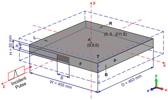
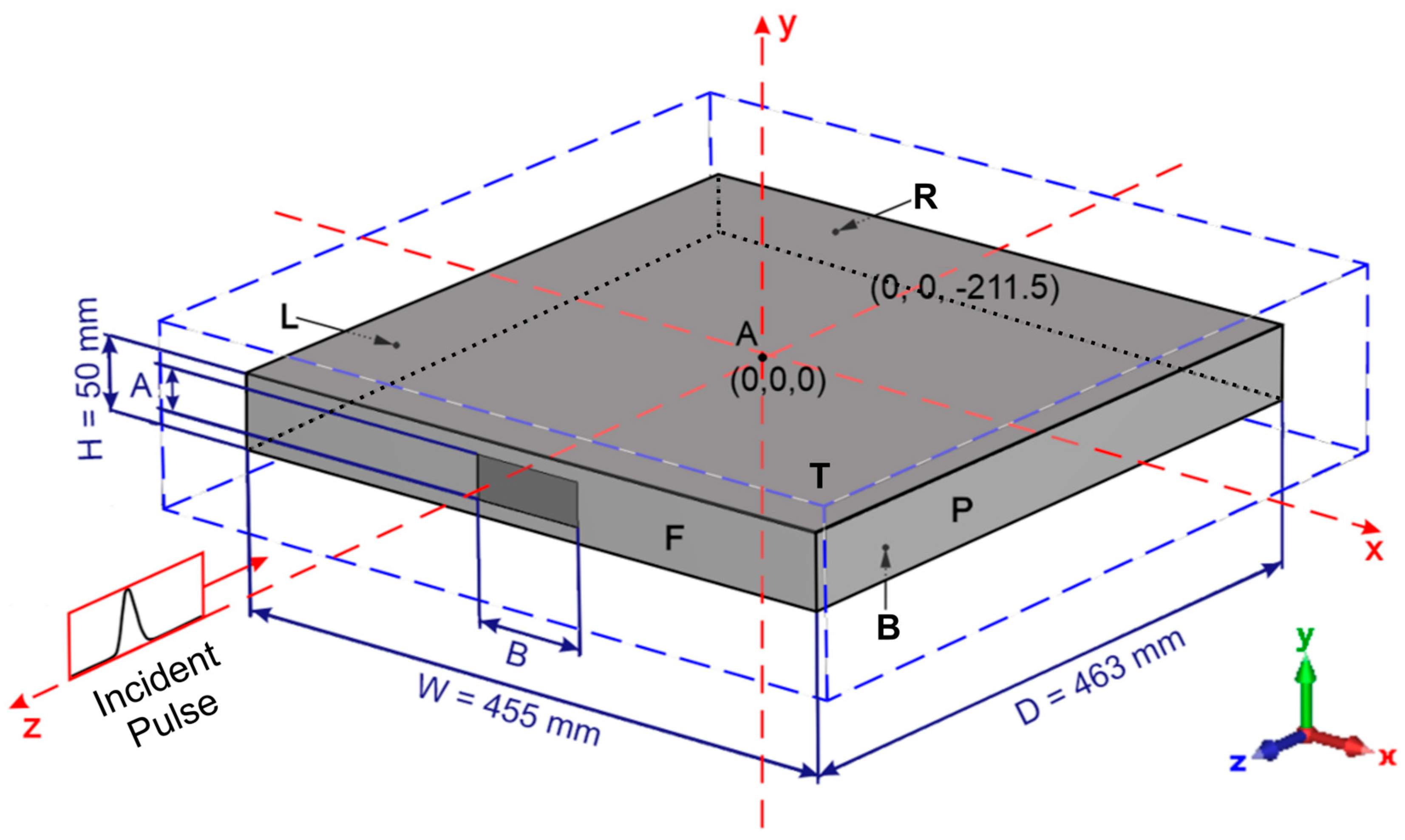
Figure 1 illustrates the design of the cuboidal shielding enclosure with rectangular aperture (later called simply “the enclosure”) placed in the rectangular coordinate system. The enclosure cuboid has a relatively low height H compared to its width W and depth D. The narrow rectangular aperture, centrally located on the front wall of the enclosure, simulates a ventilation or a cable duct passage.
Figure 1.
Geometry of the enclosure with aperture placed in the rectangular coordinate system. The origin of the coordinate system is located at the geometric center of the enclosure (point A). The EM plane wave pulse propagates in the -z direction. Polarizations of the EM plane wave pulse: perpendicular (the electric field strength vector directed in the +y direction), parallel (vector directed in the +x direction). F—front wall, R—rear wall, T—top wall, B—bottom wall, L—left wall, P—right wall. The dimensions of the aperture are 30 mm × 80 mm. H,W,D—Height, Width and Depth respectively.
There is a growing demand for small, transportable shielding enclosures intended for the temporary protection of sensitive electronics against intentional electromagnetic interference, particularly in field, laboratory, and mobile operating scenarios. Such enclosures are increasingly relevant for portable test equipment, compact control units, and emergency or diagnostic electronics, where compact form factors and low-profile geometries are required.
For this reason, shielding enclosures with a low height-to-width ratio (H < W, D) represent a realistic and practically relevant class of protection solutions. The compact geometry considered in this work reflects these application-driven constraints and enables systematic investigation of ultrashort-pulse electromagnetic coupling and shielding behavior in portable enclosures.
Such geometries of the enclosure and aperture suggest different susceptibility of the enclosure interior to the polarization of the incident EM pulse. The enclosure walls are made of the perfect electric conductor (PEC). The thickness of the enclosure walls is 1 mm.
3. Subnanosecond EM Plane Wave Pulse
The incident subnanosecond high-power EM plane-wave pulse was propagating perpendicularly (normal incidence) towards the enclosure front wall (i.e., in the -z direction, Figure 1). Due to the cuboidal geometry of the shielding enclosure with rectangular aperture, two polarizations of the incident EM plane-wave pulse were considered: the perpendicular and parallel polarizations. In the case of perpendicular polarization, the electric field strength vector of the incident EM plane-wave pulse was directed in the +y direction, i.e., perpendicularly to the top and bottom walls of the enclosure and the longer edges of the aperture. For the parallel polarization of the EM plane wave pulse, the vector was directed in the +x direction, i.e., parallel to the top and bottom walls of the enclosure and the longer edges of the aperture. The perpendicular and parallel polarizations refer to the incident EM plane-wave. The polarization of the EM field developed within the enclosure can differ from that of the incident EM plane wave.
Intentional electromagnetic interference scenarios are most commonly associated with ultrashort, high-power electromagnetic pulses. Numerous experimental and analytical studies indicate that such disturbances are more likely to involve sub- and nanosecond pulses with very fast rise times and broad frequency spectra rather than long-duration continuous-wave excitations.
From a practical perspective, ultrashort pulses are particularly effective because they can induce large transient voltages and currents in electronic circuits despite relatively low total energy, making them a plausible and efficient intentional threat. For this reason, subnanosecond UWB pulses are widely regarded as the most critical excitation type for assessing electromagnetic vulnerability and shielding performance of compact enclosures.
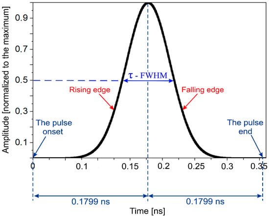
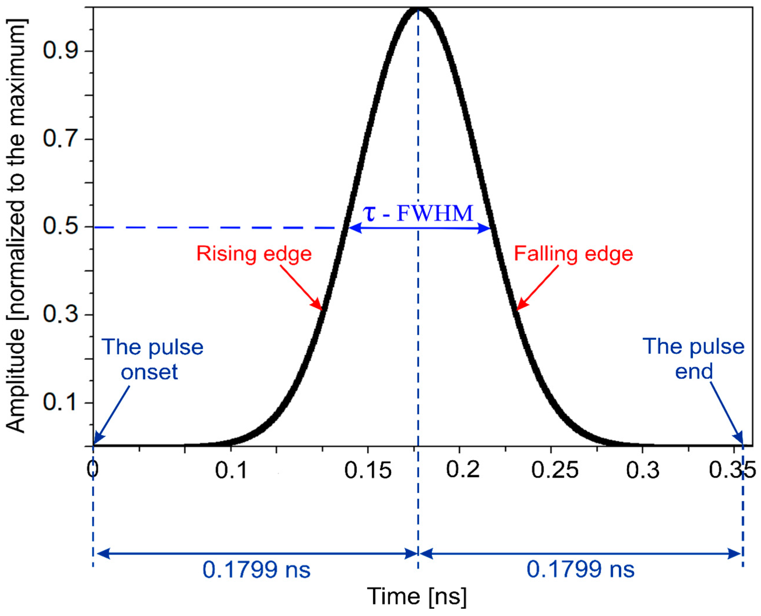
The incident EM plane-wave pulse had the Gaussian shape (Figure 2). Its parameters were as follows: the maximum electric field strength amplitude—106 V/m, and the maximum magnetic field strength amplitude—2.68·103 A/m. The Full Width at Half Maximum (FWHM) of the incident EM pulse was τ = 0.0804 ns.
Figure 2.
Time dependence of the electric field strength (or the magnetic field strength) of the normalized incident Gaussian EM plane wave pulse.
In this paper the time scale is fixed as follows: time t = 0—the incident EM plane-wave pulse onset “touches” the external surface of the front enclosure wall, t = 0.1779 ns—the maxima of the electric and magnetic fields of the EM plane-wave pulse pass the external surface of the front enclosure wall, t = 2·0.1779 ns = 0.3558 ns—the incident EM plane-wave pulse end “touches” the external surface of the front enclosure wall. The intensities of the electric and magnetic fields of the incident EM plane-wave pulse at its onset and end are assumed to be equal to zero.
4. Simulation Results
4.1. Development of the Electromagnetic Field in the Enclosure with an Aperture
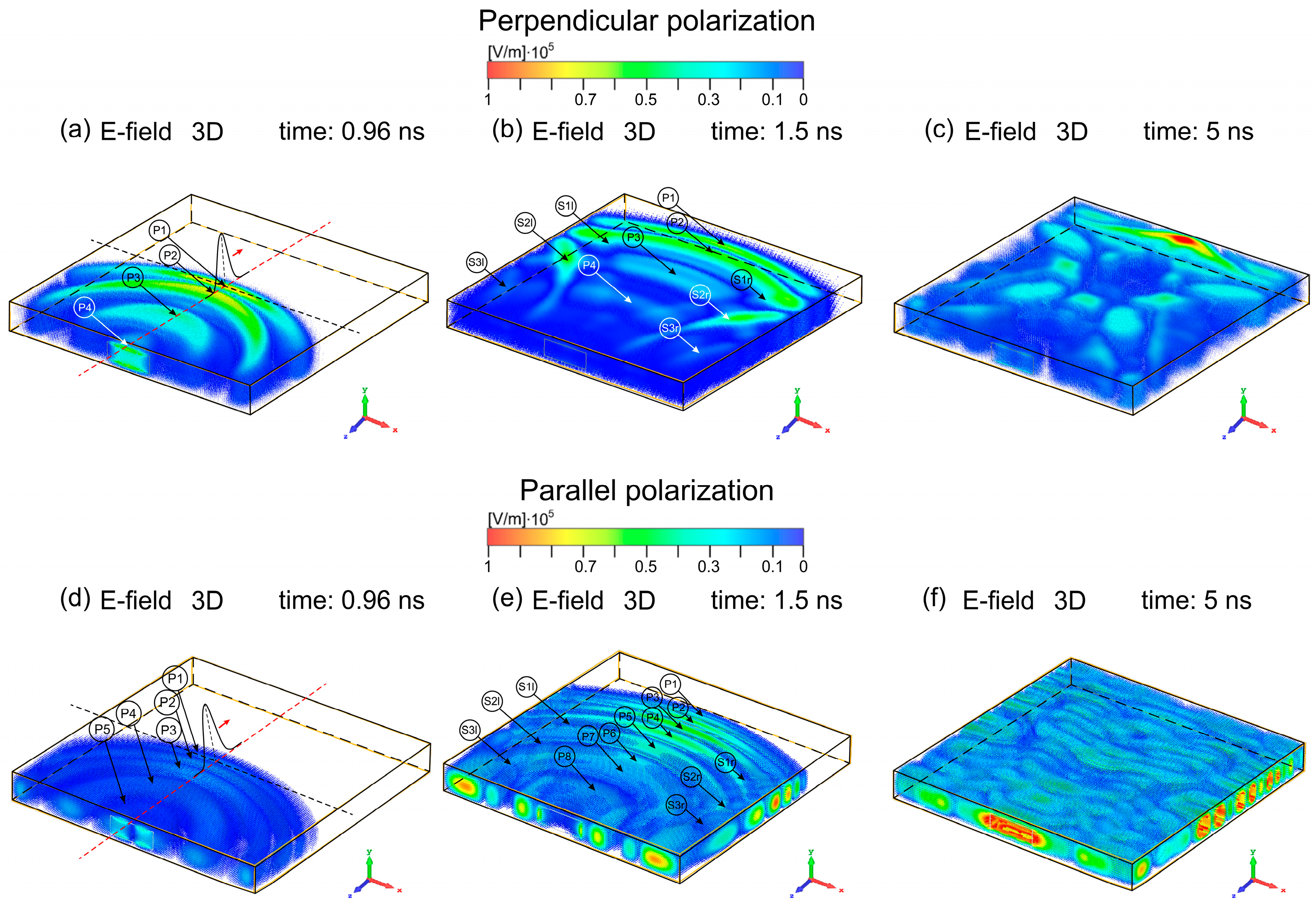
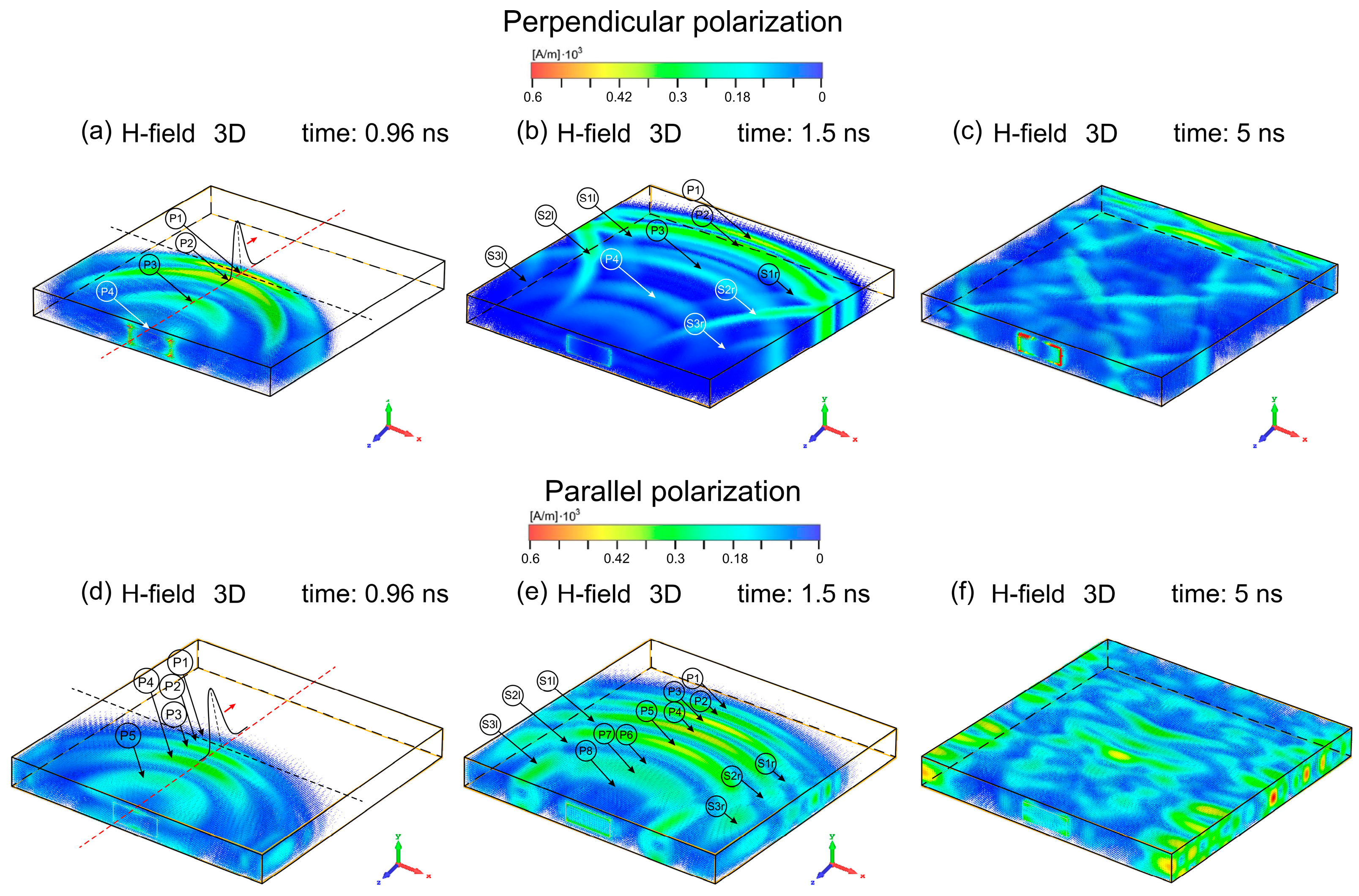
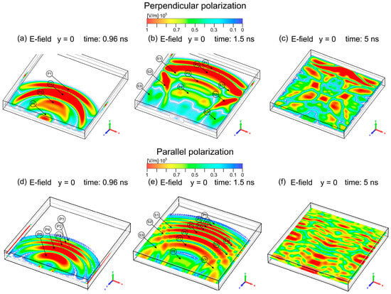
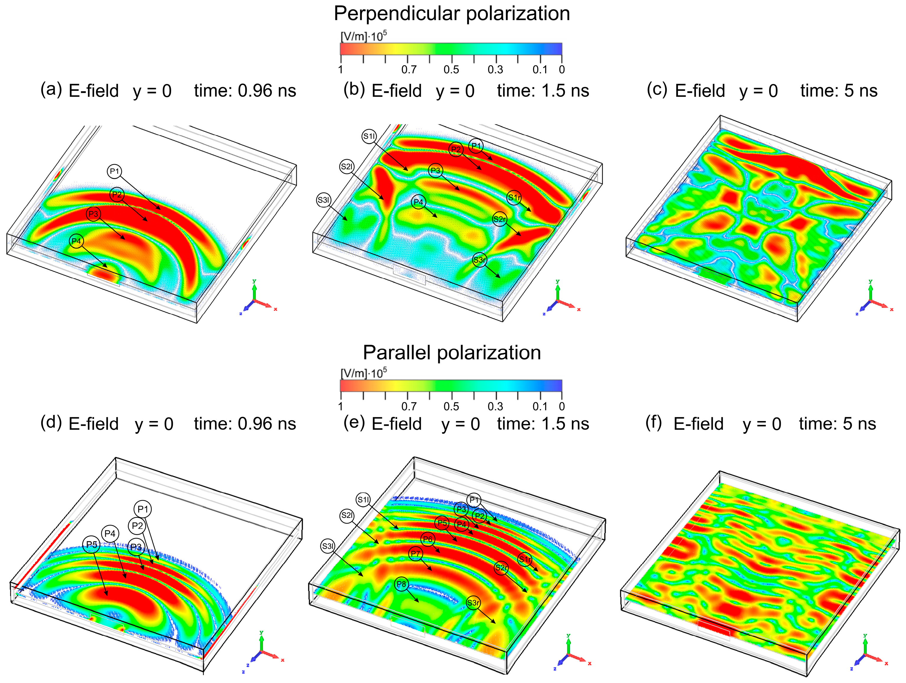
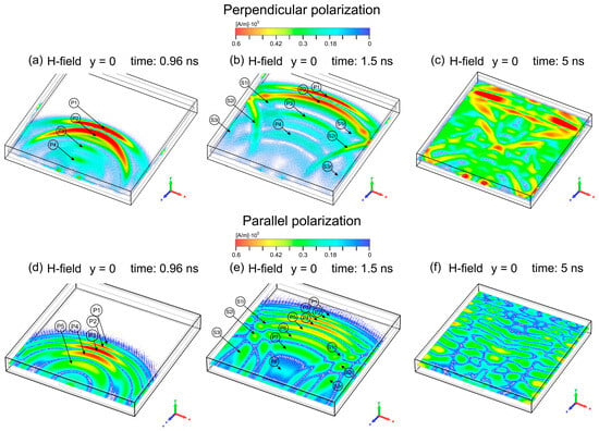
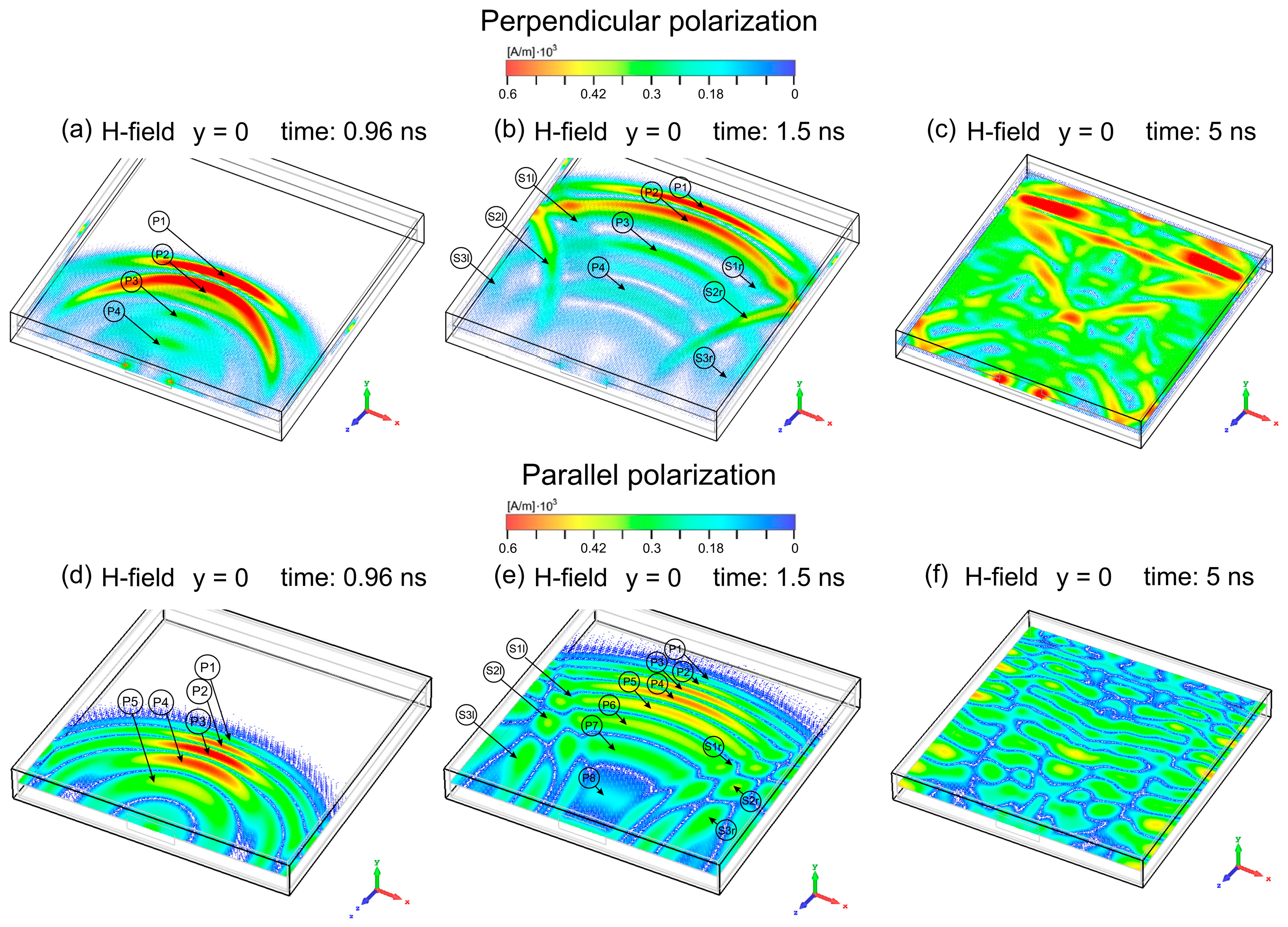
As discussed in our previous studies [15,16], the interaction of a subnanosecond plane-wave electromagnetic pulse with a small rectangular metallic enclosure containing a rectangular aperture leads to a highly dynamic and polarization-dependent field evolution within the enclosure. Figure 3, Figure 4, Figure 5 and Figure 6 present selected three-dimensional and two-dimensional field distributions at representative time instants, illustrating the temporal and spatial development of the electric and magnetic fields for perpendicular (Figure 3a–c, Figure 4a–c, Figure 5a–c and Figure 6a–c) and parallel (Figure 3d–f, Figure 4d–f, Figure 5d–f and Figure 6d–f) polarizations of the incident pulse.
Figure 3.
Development (3D) of the electric field inside the enclosure for selected times t after t = 0 (i.e., when the onset of the incident pulse “touches” the front wall of the enclosure). The outer boundary of the visualization area corresponds to the internal surfaces of the enclosure walls. The current position of the incident pulse is marked in (a) and (d). Incident pulse polarizations: perpendicular (a)–(c), and parallel (d)–(f). The wave phase—(a), (b), (d), and (e). The interference phase: (c) and (f). P1, P2, P3, P4, P5, P6, P7, and P8—primary waves, S1l, S2l, S3l, S1r, S2r, and S3r—secondary waves.
Figure 4.
Development (3D) of the magnetic field inside the enclosure for selected times t after t = 0 (i.e., when the onset of the incident pulse “touches” the front wall of the enclosure). The outer boundary of the visualization area corresponds to the internal surfaces of the enclosure walls. The current position of the incident pulse is marked in (a) and (d). Incident pulse polarizations: perpendicular (a)–(c), and parallel (d)–(f). The wave phase—(a), (b), (d), and (e). The interference phase: (c) and (f). P1, P2, P3, P4, P5, P6, P7, and P8—primary waves, S1l, S2l, S3l, S1r, S2r, and S3r—secondary waves.
Figure 5.
Development (2D) of the electric field inside the enclosure for selected times t after t = 0 (i.e., when the onset of the incident pulse “touches” the front wall of the enclosure). The outer boundary of the visualization area corresponds to the internal surfaces of the enclosure walls. Incident pulse polarizations: perpendicular (a)–(c), and parallel (d)–(f). The wave phase—(a), (b), (d), and (e). The interference phase: (c) and (f). P1, P2, P3, P4, P5, P6, P7, and P8—primary waves, S1l, S2l, S3l, S1r, S2r, and S3r—secondary waves.
Figure 6.
Development (2D) of the magnetic field inside the enclosure for selected times t after t = 0 (i.e., when the onset of the incident pulse “touches” the front wall of the enclosure). The outer boundary of the visualization area corresponds to the internal surfaces of the enclosure walls. Incident pulse polarizations: perpendicular (a)–(c), and parallel (d)–(f). The wave phase—(a), (b), (d), and (e). The interference phase: (c) and (f). P1, P2, P3, P4, P5, P6, P7, and P8—primary waves, S1l, S2l, S3l, S1r, S2r, and S3r—secondary waves.
The field evolution inside the enclosure can be clearly divided into two successive phases: a wave phase and an interference phase. During the wave phase (Figure 3a,b, Figure 4a,b, Figure 5a,b and Figure 6a,b for perpendicular polarization and Figure 3d,e, Figure 4d,e, Figure 5d,e and Figure 6d,e for parallel polarization), the incident EM pulse excites electromagnetic waves that propagate from the front wall toward the rear wall of the enclosure. The geometry of these waves is strongly dependent on the polarization of the incident field. For perpendicular polarization, the electric field forms incomplete three-dimensional ring-like structures whose longitudinal cross-sections resemble crescent shapes, while their transverse cross-sections are approximately rectangular. In contrast, for parallel polarization, the electric field assumes the form of U-shaped cylindrical structures with oval cross-sections. At the earliest stage of the wave phase, the bases of these U-shaped structures originate at the inner surface of the front enclosure wall and gradually extend toward the side walls as propagation continues. In both polarization cases, the magnetic field distributions surround their electric counterparts in accordance with Maxwell’s equations. The waves generated during this stage are referred to as primary waves (P1, P2, P3, P4, P5, P6, P7, and P8). A larger number of distinct primary waves is observed for parallel polarization compared to perpendicular polarization, reflecting the different coupling mechanisms associated with the aperture geometry. In both cases, the wave patterns exhibit symmetry about the enclosure’s longitudinal (z) axis.
As the primary waves propagate toward the rear wall, their lateral components reflect from the side walls, generating secondary waves (S1l, S1r, S2l, S2r, S3l, and S3r) that travel obliquely toward the rear of the enclosure. Upon reaching the rear wall, both primary and secondary waves reflect and propagate back toward the front wall, where further reflections occur. Repeated reflections between the front and rear walls result in progressive wave superposition and the onset of the interference phase.
During the interference phase (Figure 3c, Figure 4c, Figure 5c and Figure 6c for perpendicular polarization and Figure 3f, Figure 4f, Figure 5f and Figure 6f for parallel polarization), the electromagnetic field inside the enclosure evolves into complex, time-varying interference patterns. These patterns resemble mosaics composed of localized regions (“islands”) of enhanced or reduced field intensity. Although the spatial distribution of these regions changes in a nontrivial manner over time, the overall symmetry with respect to the longitudinal axis is preserved.
For both polarizations, the electromagnetic field induced inside the enclosure persists for a duration far exceeding that of the incident subnanosecond pulse. The wave phase terminates at approximately t = 1.54 ns, corresponding to the first reflection of the primary wave P1 from the rear wall and the cessation of direct excitation by the incident pulse. The subsequent interference phase was monitored up to t = 90 ns.
The average field intensity within the enclosure decreases monotonically due to energy leakage through the aperture and redistribution of energy throughout the enclosure volume. At t = 90 ns—approximately 88.5 ns after the end of direct excitation—the electric and magnetic field amplitudes are reduced by roughly a factor of 30 relative to the incident pulse. Nevertheless, the remaining field intensities remain substantial, reaching approximately 3.5·104 V/m for the electric field and 1.5·102 A/m for the magnetic field, indicating prolonged electromagnetic exposure within the enclosure.
4.2. Time-Dependent Local Electromagnetic Disturbance: Internal EM Pulse Series
For both polarizations, the oscillatory electromagnetic fields inside the enclosure—initially in the form of primary and secondary waves and later as interference patterns—continuously disturb the enclosure interior. As a result, observation points within the enclosure experience repeated crossings of rapidly varying coupled electric and magnetic fields. This sequence of disturbances is referred to here as a train-like series of internal electromagnetic pulses, and the disturbance experienced at a given point is termed the time-dependent local EM disturbance.
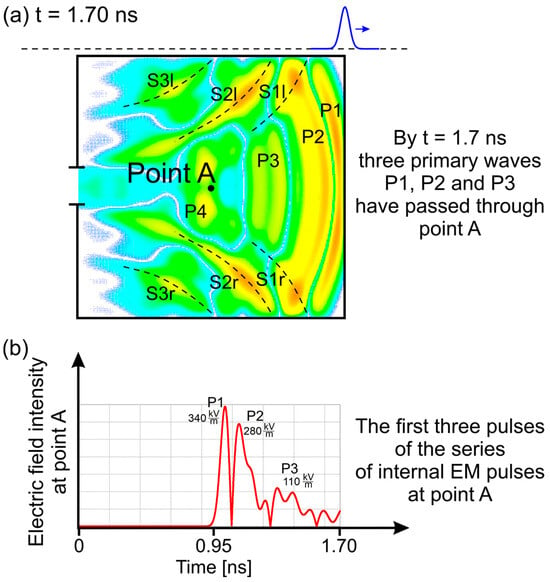
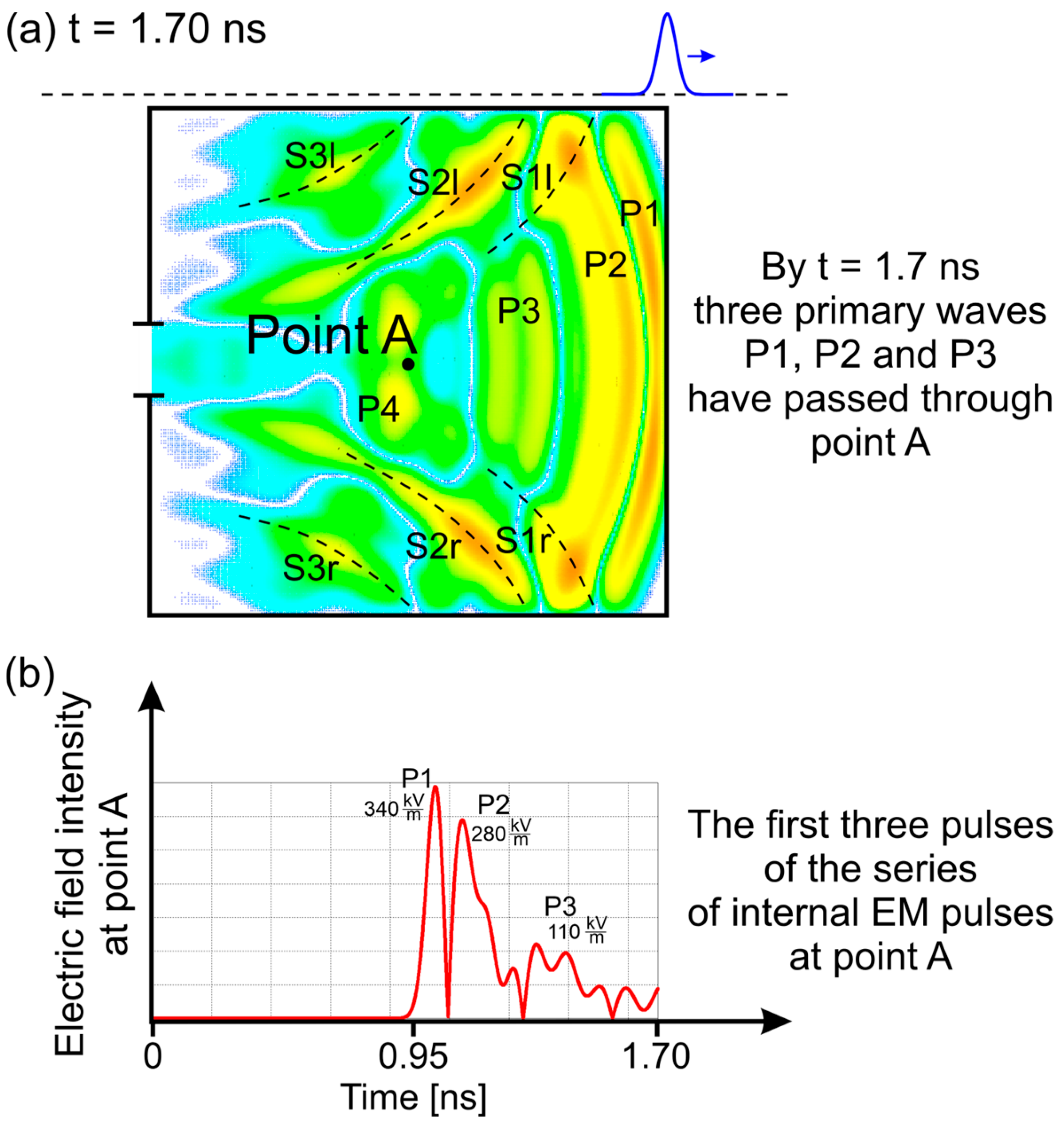
Considering perpendicular polarization as a representative example (with analogous behavior observed for parallel polarization), Figure 7a,b illustrate how primary and secondary waves give rise to internal EM pulses. Figure 7a shows the spatial distribution of the first four primary electric waves (P1–P4) and several secondary waves (S1l, S2l, S3l, S1r, S2r, and S3r) at t = 1.70 ns in the central cross-section of the enclosure (y = 0). At this time, primary waves P1–P3 have already passed the central observation point A, while the distorted primary wave P4—modified through interaction with secondary waves—is approaching it.
Figure 7.
Interpretation of a series of internal EM pulses. Perpendicular polarization. (a) The first four primary electric waves P1, P2, P3, and P4 (and the reflected waves S1l, S2l, S3l, S1r, S2r, and S3r) at t = 1.70 ns in the cross-section through the center of the enclosure (point A) in y = 0 plane. (b) The time dependence of the magnitude of the electric field strength at point A by t = 1.70 ns after passing of the first three primary waves P1, P2, and P3. The first three pulses of the series of internal pulses at point A.
Figure 7b presents the corresponding time dependence of the electric field strength recorded at point A. Each passage of a primary wave through this point manifests as a distinct internal electric field pulse. Thus, by t = 1.70 ns, point A has experienced three internal electric field pulses accompanied by corresponding internal magnetic field pulses. The peak amplitudes of these electric pulses—0.34·106 V/m, 0.28·106 V/m, and 0.11·106 V/m—are lower than the incident pulse amplitude (106 V/m), while their durations remain in the subnanosecond range.
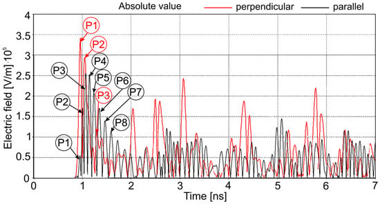
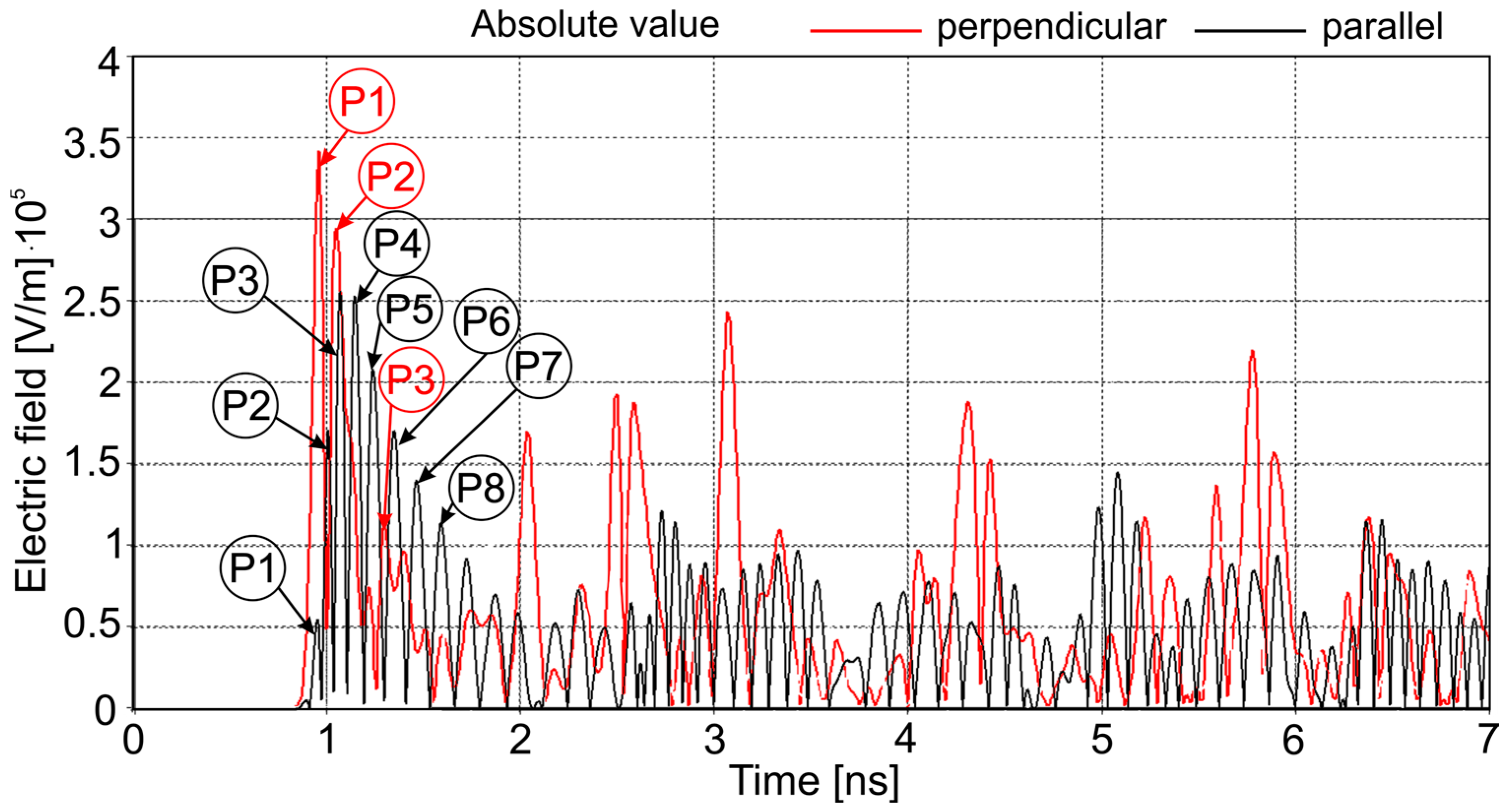
As time progresses, subsequent primary and secondary waves, followed by evolving interference patterns, continue to traverse the enclosure interior. Each crossing of point A produces an additional internal EM pulse. Consequently, the observation point is subjected to a long-lasting series of internal EM pulses. The time histories of these pulse series recorded at point A in the time range from 0 to 7 ns for perpendicular and parallel polarizations are shown in Figure 8 and Figure 9.
Figure 8.
Time dependencies of the magnitude of the electric field strength of the internal EM pulses at point A for perpendicular and parallel polarizations of the incident EM pulse in the time range from 0 to 7 ns. P1, P2, P3, P4, P5, P6, P7, and P8—primary waves.
Figure 9.
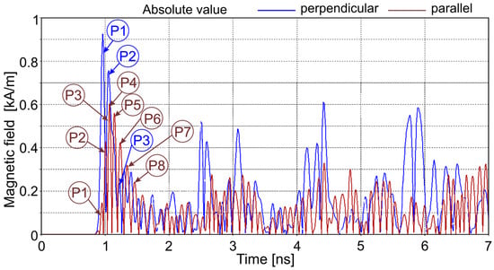
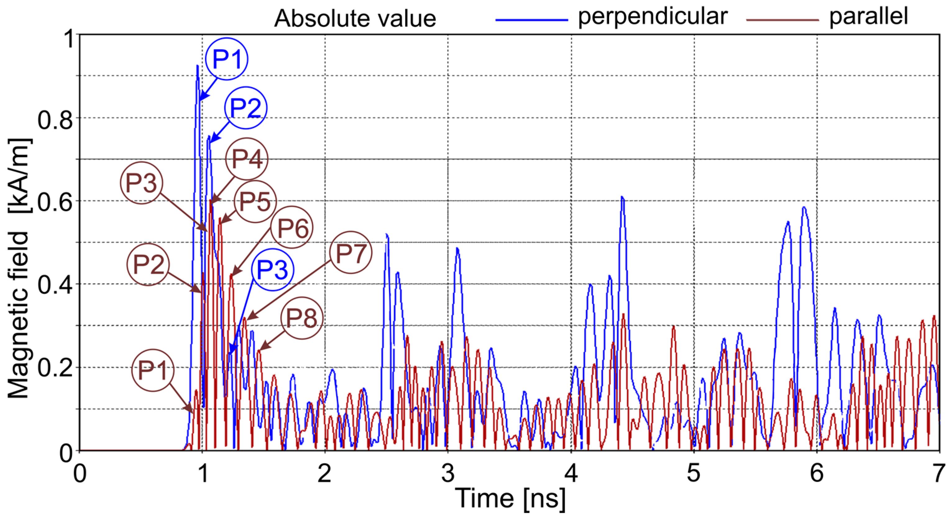
Time dependencies of the magnitude of the magnetic field intensity of the internal EM pulses at point A for perpendicular and parallel polarizations of the incident EM pulse in the time range from 0 to 7 ns. P1, P2, P3, P4, P5, P6, P7, and P8—primary waves.
The results demonstrate that the internal EM pulse amplitudes remain significant throughout the simulation duration. For perpendicular polarization, the maximum internal electric field amplitude reaches approximately 3.4·105 V/m, while for parallel polarization it reaches approximately 2.6·105 V/m. These values are only three to four times lower than the incident pulse amplitude. Corresponding magnetic field amplitudes reach approximately 920 A/m and 600 A/m for perpendicular and parallel polarizations, respectively. Such field levels are sufficiently high to constitute a serious electromagnetic hazard to electronic components located within the enclosure, particularly along the longitudinal axis.
4.3. Transformation of the EM Impact Due to Shielding with an Aperture
The use of a shielding enclosure with an aperture fundamentally alters the nature of electromagnetic exposure inside the protected volume. In the absence of shielding, an unprotected point is subjected to a single subnanosecond EM pulse whose effect is confined to the pulse duration (approximately 0.35 ns). In contrast, when shielding with an aperture is employed, the incident pulse excites a complex internal field that repeatedly interacts with the enclosure interior.
As demonstrated above, a single incident subnanosecond pulse generates a long-lasting sequence of internal EM pulses that persist for at least 90 ns—approximately 260 times the duration of the original excitation. During this time, a point inside the enclosure may be exposed to several hundred internal EM pulses. Although the amplitudes of these pulses are reduced relative to the incident pulse by a factor of approximately 3–10, their cumulative effect represents a substantial electromagnetic threat.
Importantly, this transformation of the EM impact—from a single transient event to a prolonged sequence of high-intensity disturbances—occurs for both perpendicular and parallel polarizations of the incident pulse.
4.4. Shielding Effectiveness of the Enclosure with an Aperture
The time-domain field distributions presented in Figure 3, Figure 4, Figure 5 and Figure 6 provide a basis for quantitative assessment of shielding effectiveness. Two complementary approaches are employed: (i) local time-dependent shielding effectiveness, evaluated at selected points inside the enclosure, and (ii) time-fixed global shielding effectiveness, represented as spatial maps over selected enclosure cross-sections.
The present analysis considers only the magnitudes of the electric and magnetic fields when computing shielding effectiveness. Directional effects of the internal fields, which may be relevant for specific coupling scenarios, are beyond the scope of this study.
4.4.1. Time-Dependent Local Shielding Effectiveness
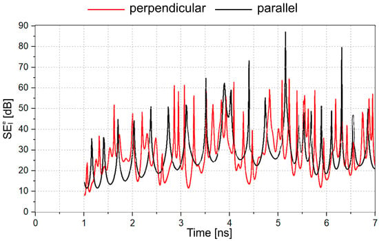
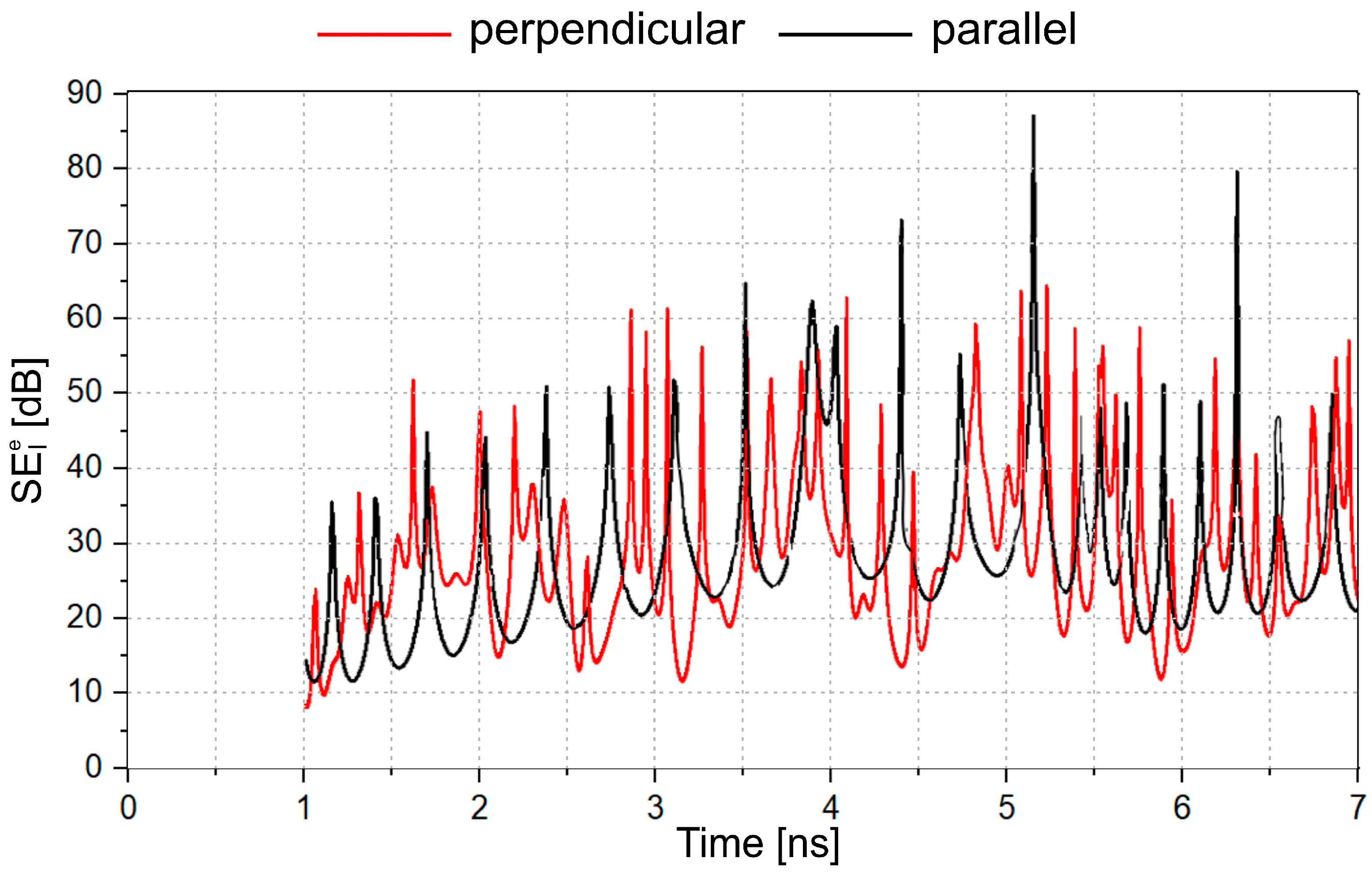
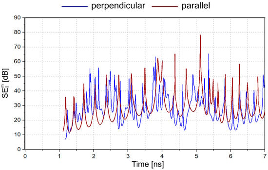
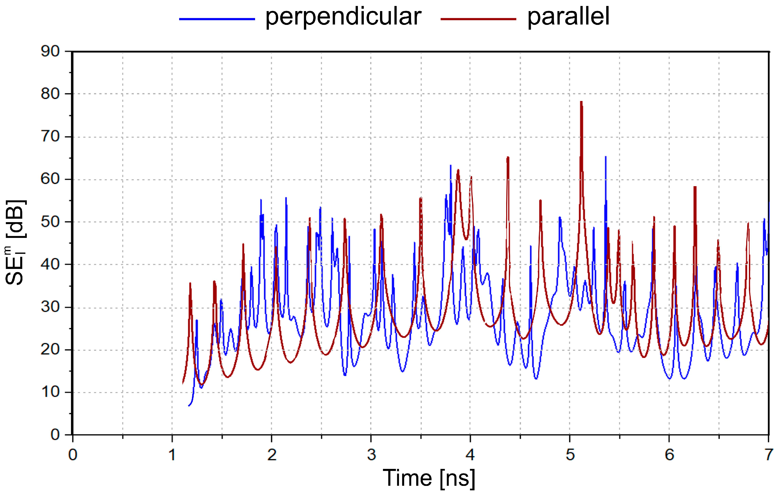
Figure 10 and Figure 11 present the time-dependent local shielding effectiveness for the electric field () and magnetic field () at point A for perpendicular and parallel polarizations, respectively. Consistent with the pulsed nature of the internal EM disturbances (Figure 8 and Figure 9), both and exhibit pronounced temporal modulation.
Figure 10.
Time dependencies of the local shielding effectiveness for the electric field at point A (0, 0, 0) for perpendicular polarization (red) and parallel polarizations (black) of the incident EM pulse in the time range from 0 to 7 ns.
Figure 11.
Time dependencies of the local shielding effectiveness for the magnetic field at point A (0, 0, 0) for perpendicular polarization (blue) and parallel polarizations (brown) of the incident EM pulse in the time range from 0 to 7 ns.
In the worst-case instances, the local shielding effectiveness does not exceed approximately 10 dB for perpendicular polarization and 12 dB for parallel polarization. For both polarizations, the minimum shielding effectiveness gradually increases with time, reflecting the progressive redistribution and leakage of electromagnetic energy from the enclosure.
Although the results shown correspond to a single observation point, the same procedure can be readily applied to other locations within the enclosure to obtain a comprehensive local SE characterization.
4.4.2. Time-Fixed Global Shielding Effectiveness
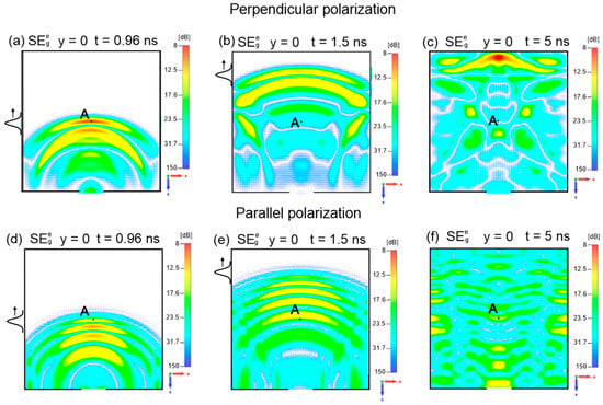
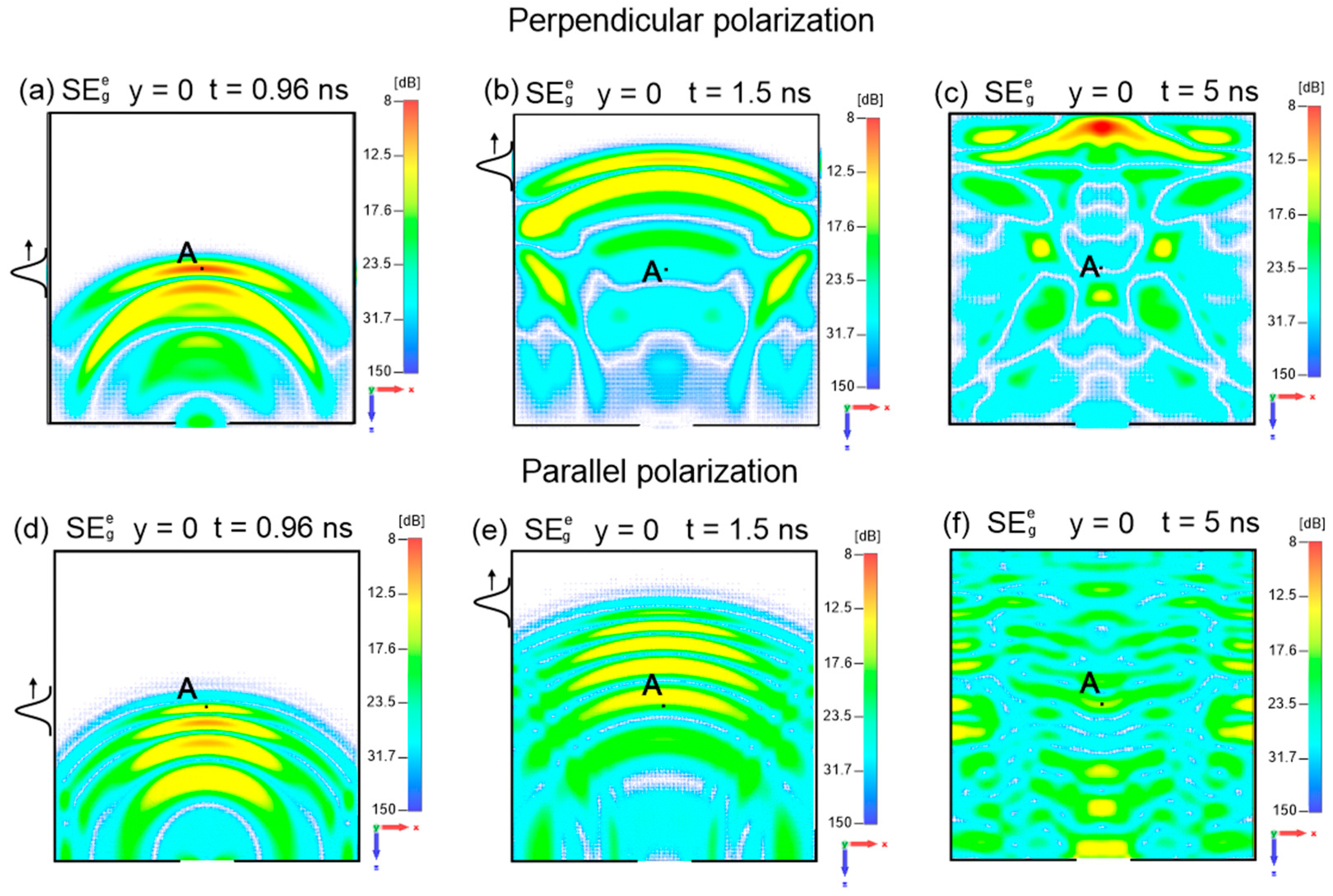
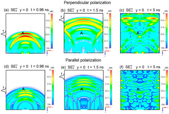
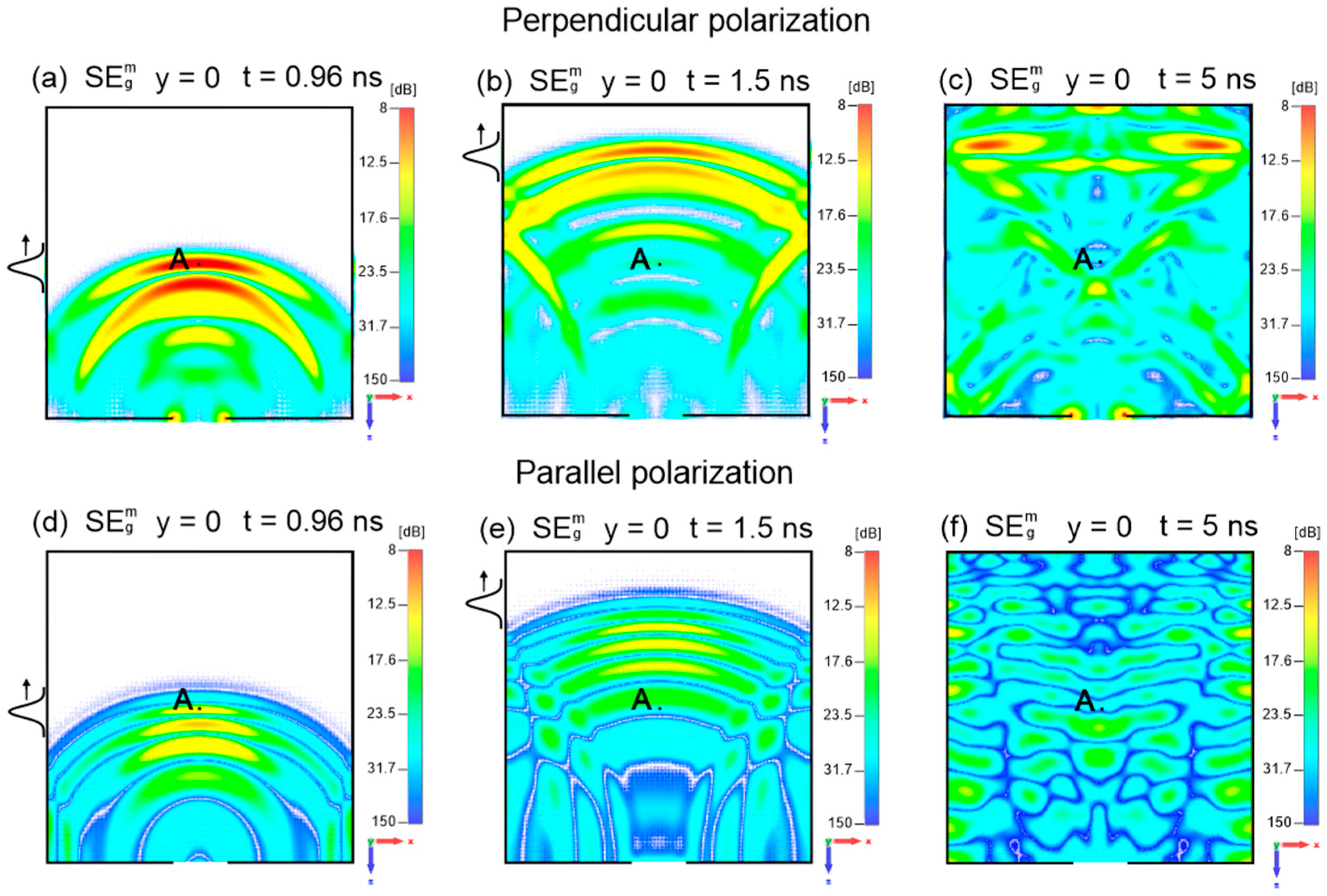
The availability of time-resolved three-dimensional field data enables the construction of spatial maps of global shielding effectiveness at fixed times. Figure 12 and Figure 13 show representative and maps in the xz-plane at y = 0 for selected times corresponding to the wave phase (t = 0.96 ns and t = 1.5) and the interference phase (t = 5 ns).
Figure 12.
Global maps of the shielding effectiveness for the electric field at times t = 0.96 ns, t = 1.5 ns (the cases of the wave phase), and t = 5 ns (the case of the interference phase) in the plane y = 0 for perpendicular and parallel polarizations of the incident EM pulse. The position of the incident EM pulse is shown on the left side of the enclosure. A—the central observation point. Incident pulse polarizations: perpendicular (a)–(c), and parallel (d)–(f).
Figure 13.
Global maps of the shielding effectiveness for magnetic field at times t = 0.96 ns, t = 1.5 ns (the cases of the wave phase) and t = 5 ns (the case of the interference phase) in the plane y = 0 for perpendicular and parallel polarizations of the incident EM pulse. The position of the incident EM pulse is shown on the left side of the enclosure. A—the central observation point. Incident pulse polarizations: perpendicular (a)–(c), and parallel (d)–(f).
These global maps allow rapid identification of regions within the enclosure that are most vulnerable to electromagnetic exposure. During the wave phase, the lowest shielding effectiveness occurs near the longitudinal axis opposite the aperture for both polarizations. For perpendicular polarization, constructive interference near the side walls leads to locally reduced shielding effectiveness, whereas for parallel polarization similar effects emerge predominantly during the interference phase.
5. Summary and Conclusions
This work presents a comprehensive time-domain numerical investigation of electromagnetic shielding effectiveness in a compact rectangular metallic enclosure with a low height-to-width ratio and a rectangular front-wall aperture exposed to a high-power subnanosecond plane-wave electromagnetic pulse. The study extends previous analyses by focusing explicitly on the effects of the polarization (perpendicular or parallel) of the incident high-power subnanosecond plane-wave EM pulse on the shielding effectiveness of the enclosure.
Time-domain simulations performed using CST Microwave Studio reveal that the electromagnetic field inside the enclosure evolves through two distinct phases: an initial wave phase characterized by the formation of primary and secondary subnanosecond EM waves, followed by a prolonged interference phase in which complex, time-varying field patterns persist within the enclosure. Although the incident pulse duration is less than 0.5 ns, the induced internal electromagnetic field remains present for at least 90 ns.
A key finding is that a single incident subnanosecond pulse generates a long-lasting train-like series of internal electromagnetic pulses that repeatedly traverse the enclosure interior. While the amplitudes of these internal pulses are reduced relative to the incident pulse, they remain sufficiently high to constitute a significant electromagnetic hazard. Consequently, the nature of electromagnetic exposure inside the enclosure is fundamentally transformed: instead of a single transient disturbance, shielded points experience prolonged and repeated high-intensity EM interactions.
Based on the time-domain field data, both local time-dependent shielding effectiveness and global time-fixed shielding effectiveness were quantified. In addition to conventional point-based SE analysis, this work introduced and applied spatial maps of global shielding effectiveness, providing rapid visual assessment of shielding performance over extended regions of the enclosure interior.
The concept of local, time-dependent shielding effectiveness provides physical insight that cannot be obtained from a single globally averaged SE value. In the case of ultrashort electromagnetic pulse excitation, the internal field response of an enclosure is strongly non-stationary and highly non-uniform in space, with local field maxima occurring at specific times and locations despite good average shielding performance. Time-dependent local SE enables identification of worst-case temporal conditions, repeated high-amplitude internal exposures, and critical regions inside the enclosure where shielding is significantly weaker than suggested by global metrics. Therefore, while conventional SE remains useful as a summary measurand, local time-dependent SE is essential for assessing the actual electromagnetic risk to sensitive electronics under ultrashort pulse disturbances.
The analysis demonstrates a strong dependence of internal field evolution, internal pulse formation, and both local and global shielding effectiveness on the polarization of the incident electromagnetic pulse. Owing to the asymmetric geometry of the enclosure and aperture, perpendicular and parallel polarizations lead to markedly different coupling mechanisms, interference patterns, and shielding performance.
The results provide new physical insight into aperture coupling and shielding behavior in the ultrashort-pulse regime and highlight the importance of time-domain analysis for assessing electromagnetic threats posed by high-power UWB pulses. The proposed global shielding effectiveness mapping approach offers a practical diagnostic tool for the design and evaluation of compact shielding enclosures subjected to subnanosecond electromagnetic interference.
Author Contributions
Conceptualization, J.M. and M.B.; and methodology, J.M. and M.B.; investigation, J.M. and M.B.; writing—original draft preparation, J.M. and M.B.; writing—review and editing J.M. and M.B.; visualization, J.M. and M.B.; supervision, J.M. and M.B. All authors have read and agreed to the published version of the manuscript.
Funding
This research received no external funding.
Data Availability Statement
The data presented in this study are contained within the article.
Conflicts of Interest
Both authors declare no conflicts of interest.
References
- Kopp, C.; Pose, R. The Impact of Electromagnetic Radiation Considerations on Computer System Architecture; Department of Computer Science, Monash University: Clayton, VIC, Australia, 2016. [Google Scholar]
- Sabath, F. Threats of Electromagnetic Terrorism. In Proceedings of EUROEM 2012 (Book of Abstracts); ONERA: Toulouse, France, 2012. [Google Scholar]
- Nitsch, D.; Sabath, F.; Schmidt, H.-U.; Braun, C. Comparison of the HPM and UWB Susceptibility of Modern Microprocessor Boards. In Proceedings of the 15th International Zurich Symposium on EMC, Zurich, Switzerland, 18–20 February 2003; System Design and Assessment, Note 36. pp. 121–126. [Google Scholar]
- University of Maryland. High Power Microwave Technology and Effects. Presented at the Short Course to MSIC, Redstone Arsenal, AL, USA, 8–12 August 2005. [Google Scholar]
- Fei, X.; Bing, C.; Chenglong, L. Damage Efficiency Research of PCB Components under Strong Electromagnetic Pulse. Appl. Mech. Mater. 2012, 130–134, 1383–1386. [Google Scholar]
- Radasky, W.A.; Baum, C.E.; Wik, M.W. Introduction to the Special Issue on High-Power Electromagnetics (HPEM) and Intentional Electromagnetic Interference (IEMI). IEEE Trans. Electromagn. Compat. 2004, 46, 314–321. [Google Scholar] [CrossRef] [Scilit]
- IEEE Standard 299.1-2013; IEEE Standard Method for Measuring the Shielding Effectiveness of Enclosures and Boxes Having All Dimensions Between 0.1 m and 2 m. IEEE: New York, NY, USA, 2014.
- Celozzi, S.; Araneo, R. Time-Domain Shielding Effectiveness of Enclosures in the Presence of ESD. In Proceedings of the 2013 International Symposium on Electromagnetic Compatibility, Brugge, Belgium, 2-6 September 2013; IEEE: New York, NY, USA, 2013; pp. 541–544. [Google Scholar]
- Araneo, R.; Attolini, G.; Celozzi, S.; Lovatt, G. Time-Domain Shielding Performance of Enclosures: A Comparison of Different Global Approaches. IEEE Trans. Electromagn. Compat. 2016, 58, 434–441. [Google Scholar] [CrossRef] [Scilit]
- Araneo, R.; Celozzi, S. Toward a Definition of the Shielding Effectiveness in the Time Domain. In Proceedings of the IEEE International Symposium on Electromagnetic Compatibility, Denver, CO, USA, 5-9 August 2013; IEEE: New York, NY, USA, 2013; pp. 113–117. [Google Scholar]
- Celozzi, S.; Araneo, R. Alternative Definitions for the Time-Domain Shielding Effectiveness of Enclosures. IEEE Trans. Electromagn. Compat. 2014, 56, 482–485. [Google Scholar] [CrossRef] [Scilit]
- Araneo, R.; Attolini, G.; Celozzi, S.; Lovatt, G. A Global Approach to Time-Domain Shielding Problems. In Proceedings of the IEEE International Symposium on Electromagnetic Compatibility, Raleigh, NC, USA, 4-8 August 2014; IEEE: New York, NY, USA, 2014; pp. 86–90. [Google Scholar]
- Cai, X.; Sun, X.; Zhao, X. A Total Energy Reduction Shielding Effectiveness Description for Enclosures. Int. J. Appl. Electromagn. Mech. 2016, 50, 283–295. [Google Scholar] [CrossRef] [Scilit]
- Dassault Systèmes. CST Studio Suite. Available online: https://www.cst.com (accessed on 31 December 2025).
- Budnarowska, M.; Mizeraczyk, J. Temporal and Spatial Development of the EM Field in a Shielding Enclosure with Aperture after Transient Interference Caused by a Subnanosecond High-Energy EM Plane-Wave Pulse. Energies 2021, 14, 3884. [Google Scholar] [CrossRef] [Scilit]
- Budnarowska, M.; Mizeraczyk, J.; Bargieł, K. Development of the EM Field in a Shielding Enclosure with Aperture after Interference Caused by a Subnanosecond High-Power Parallelly Polarized EM Plane-Wave Pulse. Energies 2022, 16, 585. [Google Scholar] [CrossRef] [Scilit]
- Budnarowska, M.; Mizeraczyk, J. Determination of Shielding Effectiveness of a Subnanosecond High-Power EM Interference by an Enclosure with Aperture Using a Time-Domain Approach. Energies 2023, 16, 1931. [Google Scholar] [CrossRef] [Scilit]
Disclaimer/Publisher’s Note: The statements, opinions and data contained in all publications are solely those of the individual author(s) and contributor(s) and not of MDPI and/or the editor(s). MDPI and/or the editor(s) disclaim responsibility for any injury to people or property resulting from any ideas, methods, instructions or products referred to in the content. |
© 2026 by the authors. Licensee MDPI, Basel, Switzerland. This article is an open access article distributed under the terms and conditions of the Creative Commons Attribution (CC BY) license.