


Abstract
Understanding the dynamic characteristics of droplets in the orientated flow channels of Proton Exchange Membrane Fuel Cells (PEMFCs) is crucial for their effective heat and water management and bipolar plate design. Therefore, the transient transport dynamics of liquid water within orientated gas flow channels (OGFCs) of PEMFCs are investigated, and a two-phase model based on the volume of fluid (VOF) method is established in the current study. Moreover, the impacts of the size of droplets and the geometrical parameters of baffles on the removal dynamics of liquid water are examined. The results show that baffles effectively promote droplet breakup and accelerate their detachment from the Gas Diffusion Layer (GDL) surface by increasing flow instability and local shear forces. The morphology of water is altered by the high velocity of gaseous flow, which can break up into several smaller droplets and distribute them on the surface of GDL by the gas flow. The shape of the liquid water film changes from a regular cuboid to a big droplet due to the surface tension of the liquid water droplets and the hydrophobicity of the GDL surfaces. Increasing the baffle height can reduce the time needed for the removal of droplets. With the increase in L1* from 0.25 to 0.75, the drainage time decreases slightly; however, for L1* increasing from 0.75 to 1.25, the drainage time remains almost the same. The impacts of different leeward lengths, L2*, on the water coverage ratio and pressure drop are minor.
1. Introduction
The promotion of carbon neutrality policies has brought tremendous attention to the development of clean and renewable energy sources, such as wind, hydro, and solar power; however, the intermittent nature of these renewable energy sources has posed significant challenges to the stability and reliability of the power grid system [1,2,3]. Using renewable energy to produce hydrogen through water electrolysis is considered a feasible solution to resolve the instability and intermittency issues associated with these renewable energies [4,5,6]. The chemical energy of hydrogen can be converted into electrical energy in Proton Exchange Membrane Fuel Cells (PEMFCs) without producing any pollution, which is promising for the utilization of green hydrogen generated from renewable energy sources [7,8]. Nevertheless, the performance degradation and short durability of PEMFCs still impede their wide application. Proper water management can effectively remove the liquid water from the gas diffusion layer and gas flow channel, which is beneficial for improving the efficiency and long-term reliability of PEMFCs [9].
The two-phase flow in channel is key to affecting the mass transfer process in PEMFCs, as the gas entering and liquid water discharging share the passageway [10]. Geometric parameters—such as channel width, rib height, and gas flow channel (GFC) width—have significant impacts on the two-phase flow characteristics within the channel [11,12,13,14,15,16]. To explore the two-phase flow characteristics, flow regime maps have been extensively employed using experimental techniques including the neutron imaging method, direct optical visualization method, magnetic resonance imaging and X-ray radiography method. Zhan et al. reported that liquid water tends to accumulate beneath the rib regions, where the local flow velocity was lower than that under the channel [17]. Mojica et al. designed a three-dimensional (3D) nozzle flow channel, and in situ neutron images indicated that this design led to less and more uniform liquid water distribution, and the peak power density was 25% higher than the straight, wave and two-dimensional (2D) designs [18].
Owing to experimental limitations, many critical parameters, such as reactant gas concentration and current density contribution in MEA are really difficult to apply to real-time measurements. As a result, the mechanisms governing two-phase flow and corresponding optimization strategies have been widely investigated using numerical approaches, including simplified liquid saturation models, the volume of fluid (VOF) method, and the lattice Boltzmann method (LBM). Based on the M2 model, Wang et al. developed a continuum two-phase channel flow model and discussed the liquid water distribution and two-phase pressure drop. They found that the liquid water built up quickly at the entrance region, followed by a slow increase downstream under full-humidification inlet conditions; water was trapped around the geometrical heterogeneity and two-phase pressure factor was defined to understand two-phase flow maldistribution [19]. Ding et al. established the 1 + 3D half fuel cell model to explore the effect of two-phase flow in the gas flow channel on performance of PEMFCs. The result showed that the hydrophobic MEA surface was beneficial for improving the fuel cell performance, and the slug flow caused a large pressure drop, which should be avoided [20,21].
Optimizing the configuration of gas flow channels is an effective method to adjust the gas supply and water transportation, which is crucial for maintaining the water content in PEMFCs to improve the conductivity of membrane, while preventing liquid water accumulation [22,23,24,25,26]. Liu et al. designed a novel channel with a slope turn, which could enhance the water removal in the elbow region [27]. Qin et al. employed the VOF method to study liquid droplet transport in a flow channel equipped with hydrophilic needles, which could improve the water removal from the electrode surface and mitigate the blockage of gaseous reactant [28]. Similarly, Liao et al. investigated the coupled effects of geometric parameters and surface wettability on droplet removal dynamics in PEMFCs. They found that variations in draft angle could induce local vortices in GFCs, while curvature along the droplet transport direction facilitated droplet detachment [29]. Guo et al. proposed two novel channel configurations, one with a complete cuboid block and another one with two separated blocks. They found that the separated two-block channel could directly entrained liquid water away from the GDL surface, resulting in faster water removal and a smaller pressure drop [30]. Furthermore, Yang et al. numerically investigated water removal behavior and purging strategies in PEMFCs with multiple gas channels and a dead-ended anode, which were further validated using PEMFCs with a transparent end plate. The results showed that vertical cell orientation enabled more effective liquid water purging than horizontal placement [31].
The incorporation of baffle structures within conventional straight flow channels can enhance the guidance of fluid flow, intensify the mass transfer of reactants into the porous media, and consequently improve the performance of fuel cells. Ebrahimzadeh et al. numerically investigated the effects of shapes, numbers, and sizes of baffle blocks on the performance and reactant distribution of PEMFCs. They found that rectangular baffles could increase the current density by up to 50% compared to those without baffles [32]. Yin et al. studied the influence of baffle plates on the mass transport and performance of PEMFCs, and the impacts of the height and number of baffles on the gas velocity, pressure, and concentration distribution on the performance of PEMFCs. The results showed that baffle plates could increase local gas velocity, which eventually helped to promote liquid water removal and to enhance mass transport efficiency [33]. However, the rectangular baffles used in these studies increased the flow loss during reactant delivery, which led to a reduction in net power. To retain the benefits of baffles while mitigating their drawbacks, Guo et al. proposed a novel orientated baffle flow channel with the baffle having a streamlined windward side and a sloped shape leeward side. They found that this optimized baffled flow channel can reduce the power loss by 19.4%, and the cell performance can be improved by 5.7% [34]. Chen et al. further considered the Forchhemer inertial force on liquid water transport and modified the two-fluid model and found that the Forchhemer inertial force helped reduce the liquid saturation in channel and membrane electrode assembly [35]. Moreover, Chen et al. found that the uniformly distributed high baffles yielded the optimal net power by effectively mitigating downstream water accumulation and balancing enhanced mass transport and parasitic pressure losses [36]. The effects of baffle structure, especially the leeward-side length on the pressure drop and net power of PEMFCs, were examined experimentally. It was demonstrated that extending the leeward side can significantly reduce the pressure drop, shorten the pressure stabilization time, and increase both net power and power efficiency [37]. Sun et al. quantitatively analyzed the local head loss caused by baffles in flow channels. Their findings suggested that employing a streamlined windward side and avoiding sudden expansion on the leeward side can effectively reduce local losses behind the baffles [38]. Moreover, porous-blocked baffles with different porosity have been studied to enhance reactant transfer and reduce pumping loss [39].
The literature review indicates that incorporating oriented baffles in flow channels can enhance species transport through porous electrodes and improve overall cell performance [36,37,38,39,40,41]. Previous studies on OGFCs have primarily focused on mass transport behavior, water management, structural and performance optimization, and the pressure drop loss induced by channel geometry. However, the removal dynamics of liquid water in the OGFCs of PEMFCs remain insufficiently explored. The flow direction and velocity field within the OGFCs would be obviously different from those conventional gas flow channels. To further elucidate the influence of detailed two-phase flow on fuel cells’ mass transfer and performance, the fuel cell model which couples the gas–liquid surface tracking model, specifically the Volume of Fluid (VOF) model, is developed in this study. This model is employed to investigate the distribution and discharge characteristics of liquid water in OGFCs. The key parameters—discharge time, pressure drop, and water coverage ratio of the GDL surface—are used to characterize the transport dynamics of liquid water droplets in the channels. Moreover, the effects of droplet size and geometrical parameters of the baffles on the removal dynamics of liquid water droplets are investigated. The findings of this study are expected to provide valuable insights into the design and optimization of novel baffled flow channels, thereby contributing to reducing parasitic power and enhancing water management in proton exchange membrane fuel cells.
2. Model Formulation
In this work, a three-dimensional, two-phase model is proposed to investigate the impact of the structure of the orientated-type baffle on gas transport and droplet movement within the orientated gas flow channel of PEMFC.
2.1. Computational Domain
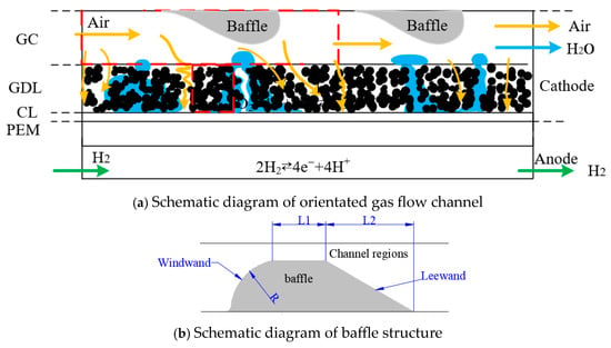
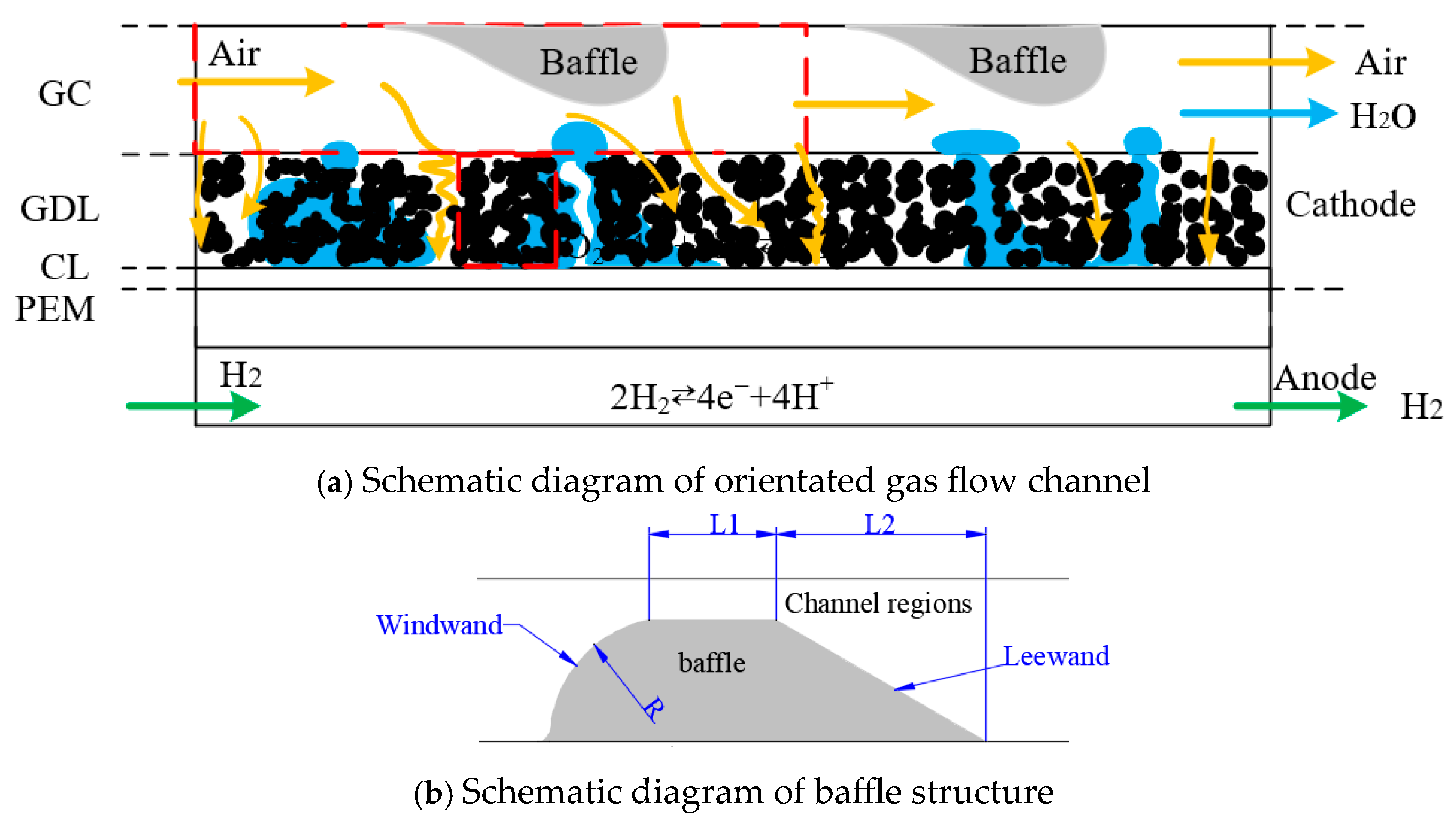
During operation, air is supplied to the cathode flow channel. Under the combined effects of forced convection and natural convection, the reactant gas is transported along the channel, while a portion of it penetrates into the gas diffusion layer (GDL) to sustain the electrochemical reactions. At the same time, the unreacted air moves through the cathode flow channels alongside the liquid water produced by the electrochemical reactions and the condensate formed at lower temperatures. To focus on the dynamics of liquid water droplets, a three-dimensional numerical model of orientated flow channel is developed, as shown in Figure 1a,b, where the schematic diagram of the orientated gas flow channel and the structure of the orientated baffle are presented. The size of the channel length is 10 mm, and the cross-section is 1 mm × 1 mm. At the bottom of the channel, an orientated baffle is introduced, with the baffle height of R, the middle baffle length of L1, and the sloped leeward baffle length of L2.
Figure 1.
Schematic diagram of (a) orientated gas flow channel and (b) baffle structure.
2.2. Governing Equations
The interface between the liquid water and gaseous flow is reconstructed and resolved by the VOF model, which is effective for the study of two-phase flow with sharp interfaces [42,43,44,45].
The following assumptions are adopted for the development of the mathematics model for the study of the removal dynamics of liquid droplets in OGFCs.
- The flow within the gas flow channel is presumed to be laminar, given the small cross-section and low Reynolds number of the gas flow.
- The gas mixture is assumed to be an incompressible ideal gas with constant physical properties.
- The surface tension coefficient between two phases is assumed to be constant.
- The impact of phase change between liquid water and vapor is neglected, due to the short time interval during the removal process of liquid water droplets and the small concentration difference in water vapor between the gas/liquid interface and the flowing gas.
- The surface of the flow channel and GDL is described using a static contact angle, assuming a smooth surface without dynamic wetting effects.
- The microstructure of the GDL surface, nor the possibility of infiltration is ignored, as this study mainly focuses on the removal dynamics of liquid water droplets under the interaction between the liquid water and gaseous flows.
Due to the fact that the cross-sectional area and velocity of the channel along the flow channel are changing, the Reynolds number is calculated to determine the flow regime of the reactant gaseous flow in the gas flow channel. The formula for the calculation of the local Reynolds number can be written as:
where represents the local hydraulic diameter, is the average gas velocity of the section, the unit is , represents the density of the gas, and represents the dynamic viscosity. Based on the simulation that the maximum flow velocity is approximately 29.5 m/s, the calculated Reynolds number is 807.81, which is less than 2300. The flow regime can be identified as laminar flow.
A transient three-dimensional simulation is performed in the current study to investigate the liquid removal process from orientated flow channels. The continuity equation, momentum conservation equation, and fluid-fraction advection equation using the VOF method are developed and solved. The governing equations are expressed as follows:
where is the time, is the pressure, and are the average liquid phase density and coefficient of viscosity, respectively. is the velocity vector, and is the surface tension.
The Continuum Surface Force (CSF) model is employed to introduce an additional tangential term at the interface based on the surface tension gradient, enabling the modeling of variable surface tension in droplets. The surface tension force, , is represented as follows:
where is the surface tension coefficient between two phases, and constant coefficient (0.0734 N/m) is used is the surface curvature defined as the divergence of the average unit vector of the interface.
The surface curvature is determined by the surface wettability of the gas flow channel, which can be written as follows:
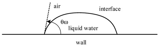
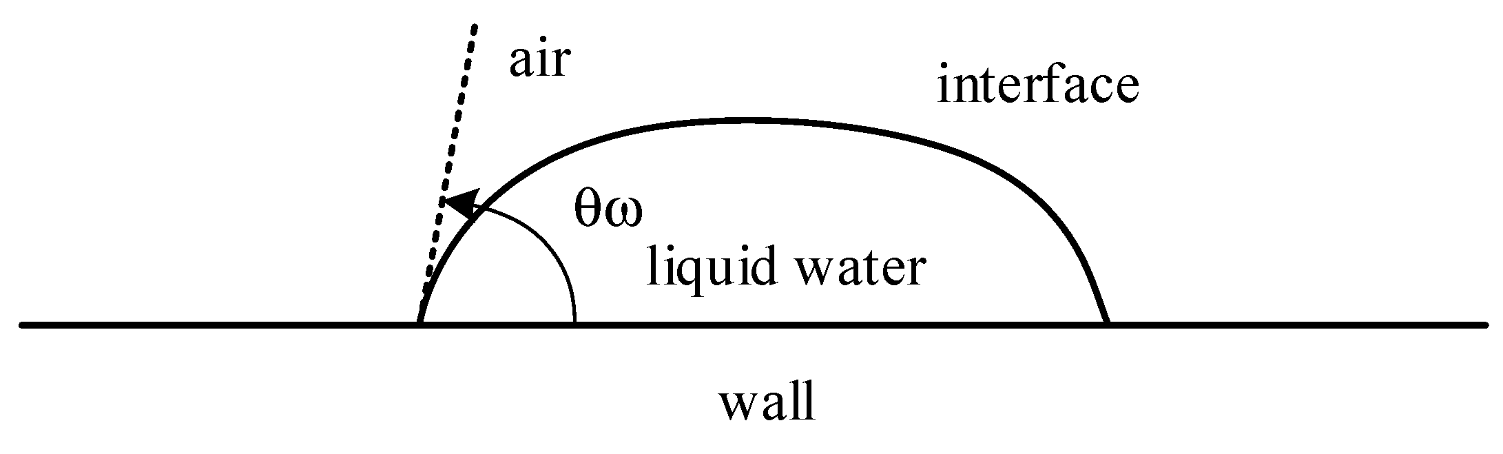
where and are the unit vector normal and tangential to the wall, respectively. is the static contact angle of the surface of the gas flow channel, where can be shown in Figure 2.
Figure 2.
The static contact angle on the wall.
The volume fraction represents the ratio of liquid phase to the gas phase within each computational cell in the VOF model. To accurately capture the interface, a volume fraction is assigned to each phase of the cell in the computational domain. This allows for a clear representation of the interface between the gas and liquid phases. The volume fraction could be calculated by follows:
in which is the fraction of liquid phase. is the volume of the phase in the computational cell, and is the total volume. The volume fractions for all fluid phases within the computational domain are one.
The average pressure, density, and viscosity of the mixture are given by follows:
The boundary conditions at the entrance of the gas flow channel is set as velocity-inlet with a value of 5 m/s, assuming that the gas flow has been fully developed at the entrance of the gas flow channel. The gas velocity () has a parabolic distribution with a direction perpendicular to the flow channel inlet. The boundary conditions at the flow channel outlet are set as a pressure-outlet boundary, and the outlet pressure is set to 101,325 pa. The boundary conditions for the governing equations can be written as follows:
At the inlet:
At the outlet:
At the walls:
in which are the velocities in the x, y, and z directions, respectively. is the maximum radius of the channel, and is the absolute pressure value pre-selected at the outlet of the channel.
At the initial moment (t = 0 s), a no-slip boundary condition is set in the computational domain. The surface wettability of the channel walls is adjusted by setting different contact angles. The selection of static contact angles is based on both physical considerations and previous experimental and numerical studies in the open literature. As the hydrophobic treatment of the GDL is widely adopted in PEMFCs through PTFE loading and surface modification, the contact angles typically exceed 120° as reported in the literature [28,29]. Thus, the static contact angle of the GDL surface is assigned to be 140°, representing a hydrophobic, PTFE-treated GDL, which is consistent with values commonly used in the literature as well [30,46]. The side and top walls of the flow channels correspond to the bipolar plate surfaces, which are generally metallic or graphite-based. These walls usually exhibit more hydrophilic behavior [47]. Therefore, a lower static contact angle of 45° is prescribed for the channel walls to reflect their preferential wettability. The surface tension coefficient for the water–air interface is taken as 0.0734 N/m, and the surface tension coefficient is 0.0734 N/m. A liquid water droplet is set as a semicircle, introduced on the GDL surface at the center-line of the channel at a distance (chosen as 3 mm) from the inlet of the channel. More detailed simulation setting parameters are listed in Table 1.
Table 1.
Summary of simulation parameters.
2.3. Numerical Implementation and Validation
The numerical models are implemented on the platform of ANSYS Workbench (version 15.0). The Geo-Reconstruct volume fraction spatial discretization algorithm and the linear segmentation method are used to establish the gas/liquid interface, in which air and water are designated as the primary and secondary phases, respectively. The gradient-adopted discretization method based on the Green-Gauss element is used for the spatial discretization, and the Pressure Staggering Option (PRESTO) scheme is employed to achieve the spatial discretization of pressure. Additionally, the second-order upwind scheme is adopted for the spatial discretization of the momentum equation. The Pressure-Implicit with Splitting of Operators (PISO) algorithm is selected for the coupling of velocity and pressure, as the PISO is suitable for tackling transient simulations [48]. This paper establishes the convergence criterion based on the global residual, and it is deemed that the calculation has been converged when the residual values of all variables fall below 10−3. The time step is selected as 10−6 s in this study, which has also been validated through the time-independent simulation.
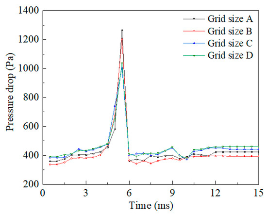
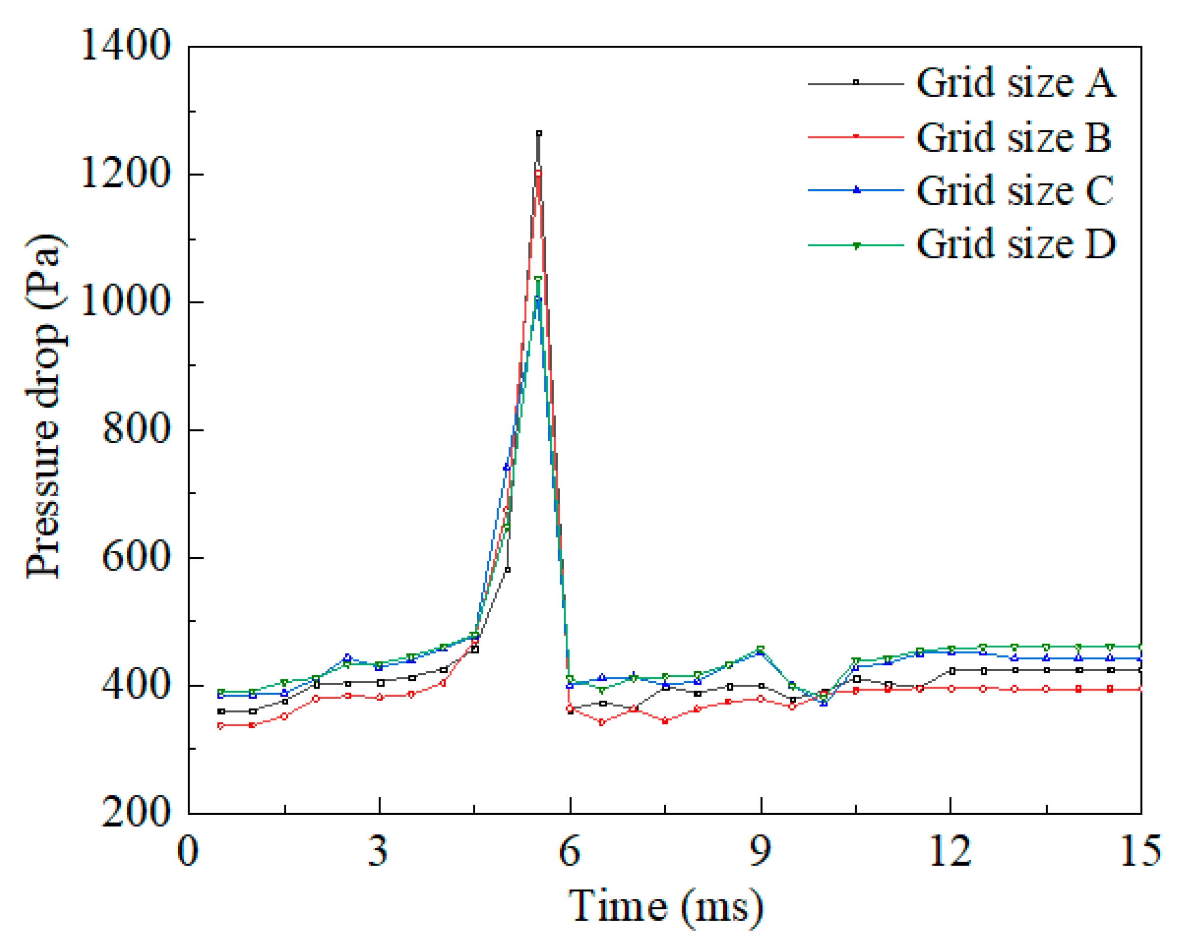
The number of grids is critical to the accuracy of the numerical simulation. Increasing the number of grids can improve the accuracy of the models, but the computational load would also increase. In this study, structured hexahedral meshes are used for the discretization of the computational domain. A comparison of pressure drops is performed to identify suitable meshes. Four different meshes, namely size-A, size-B, size-C, and size-D, with values of 50,544, 128,753, 180,770, and 309,170, respectively, are examined. Figure 3 displays the results of the grid independence test, and the results of the size-C mesh are very close to those of the size-D, and the calculation time of the size-C mesh is shorter. Therefore, the size-C mesh element is selected for subsequent simulations, considering the numerical accuracy and computational cost.
Figure 3.
Grid independence analysis.
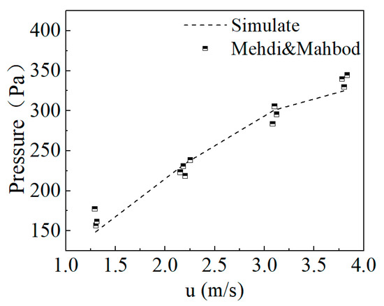
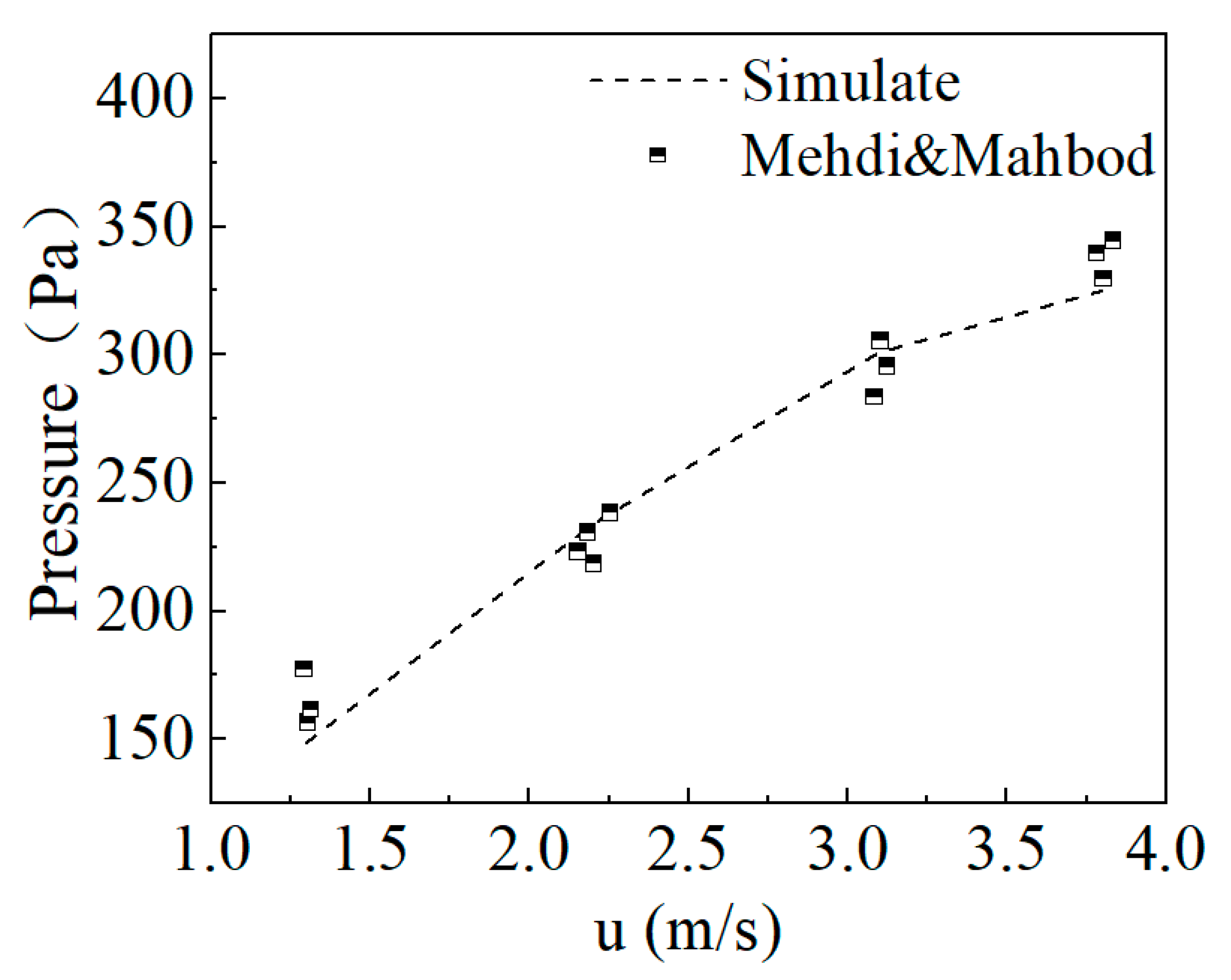
Figure 4 presents the validation results of the model by comparing the pressure drop during the liquid water removal process in a micro-channel under different air flow velocities from experimental studies from the open literature [49]. To provide a more quantitative assessment of the model accuracy, the root mean square error (RMSE) and the corresponding percentage error are employed as validation metrics.
Figure 4.
Change in channel inlet–outlet pressure drop with different air velocity.
The root mean square error (RMSE) is calculated as
and the percentage error is defined as
where denotes the number of cases, is the experimental value, is the simulation prediction value.
As summarized in Table 2, the RMSE of the predicted pressure drop ranges from 8.05 to 17.61 Pa over the investigated velocity range (1.3–3.8 ), while the percentage error remains below 10% for all cases and decreases to below 5% at moderate-to-high velocities. The smallest relative error (1.36%) is observed at an air velocity of 3.1 , indicating excellent agreement between numerical predictions and experimental measurements under typical operating conditions. It can be seen that the numerical results from the models developed in the current study can match the experimental results closely. These demonstrate that the developed model is capable of accurately reproducing the liquid water removal dynamics in gas flow channels of PEMFCs and is therefore suitable for subsequent parametric and mechanistic analyses.
Table 2.
Error metrics at different gas velocities.
3. Results and Discussion
Two different shapes droplets and liquid films, are considered in the current study for the investigation of the dynamic transport process of liquid water in OGFCs with different droplet sizes, baffle structural parameters and parasitic power, which are listed in Table 3. The transport characteristics of droplets with different sizes in the orientated gas flow channel are examined in the beginning. Subsequently, the baffle parameters of baffle height (R), middle baffle length (L1) and sloped leeward baffle length (L2) are varied to explore the impact of these key structural parameters on the liquid water transport dynamics.
Table 3.
Computational cases and related parameters. (R, L1, L2 are structure parameters of orientated baffle, is parasitic power).
The water coverage ratio noted as is defined as the ratio of the area of water in contact with the wall to the total area of the wall, which can be written as
where and represent the surface area of liquid water and wall, respectively.
The pressure drop between inlet and outlet, noted as , is defined as the pressure difference between outlet and inlet.
where and represent the pressure of inlet and outlet, respectively.
A dimensionless time, t*, is formulated to evaluate the removal time interval for the droplets in the gas flow channel. The calculation formula is
where t is the time, is the length of the flow channel, and is the average velocity of the flowing gas.
Similarly, the middle length and leeward length of the baffle are dimensionalized by dividing them by the height of the gas flow channel (H), which can be written as
in which L1 is the middle baffle length, L2 is the sloped leeward baffle length, and H is the height of the gas flow channel.
Parasitic pumping losses and net power: We now quantify the parasitic power consumption in the channel as [50].
where is the parasitic power consumption, is the area of the channel inlet, , is the pressure difference between the cathode inlet and outlet (Pa), and is the pumping efficiency, typically taken as 70% [51].
3.1. Removal Dynamics of Droplet
Since the transport of liquid water and reactant gas shares the same channel, the liquid water transport process interacts with the gas transport in the channel during the removal process of the liquid droplets. Three key parameters, discharge time, pressure drop and water coverage ratio of the GDL surface, are commonly used to characterize the transport dynamics of liquid water droplets in the gas flow channels of PEMFCs. In general, short discharge time and a small coverage ratio are beneficial for avoiding water flooding and oxygen starvation. This research defines the water discharge time as the time interval between the time instant when liquid water starts to appear on the surface of GDL and the time instant when the residual water coverage ratio of the GDL surface is less than 5% of the initial value.
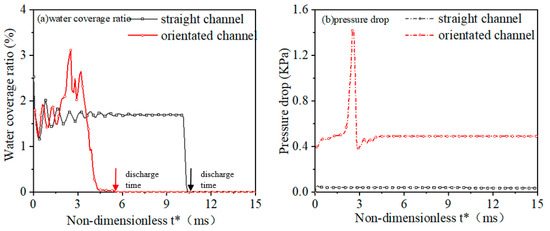
Figure 5 compares the liquid water coverage ratio on the GDL surface and the pressure drop between the inlet and outlet of the straight and OGFCs. As shown in Figure 5a, at the beginning, the water coverage ratio fluctuates, which is caused by the shape change or rupture of droplets [30,52]. Moreover, the orientated gas flow channel facilitates the removal process of the liquid droplets, and the discharge time of OGFCs can be reduced by 73.6% compared to that of conventional straight channels. To be more specific, the discharge time is about 20.8 ms in the traditional straight channel; however, the discharge time becomes 5.5 ms for the orientated channels. The liquid distribution, deformation, and fragmentation also affect the discharge time [53]. Figure 5b displays the pressure drop between the inlet and outlet for different gas flow channels. Compared with the straight channel, the pressure drop increases sharply for the orientated channel and the pressure peak can reach around 1.4 kPa at about 2.1 ms. This is because the droplet can stick to the lower surface of the baffle because of the hydrophilicity of the channel surface, which increases the inlet pressure due to the blockage effects in the presence of the baffles and droplets. The pressure gradually returns to a stable state until the droplet flows through the baffle. The pressure remains relatively stable at around 170 Pa in the straight channel, which is slightly higher than the pressure in the flow channel without liquid water droplets. These results demonstrate that adding orientated baffles in conventional straight gas flow channels helps the removal of liquid water droplets, but higher-pressure drops can be generated as well.
Figure 5.
A comparison of gas liquid transportation for different radius droplets in the orientated-type flow channel. (a) the liquid water coverage ratio on the GDL surface, (b) the pressure drop between the inlet and outlet.
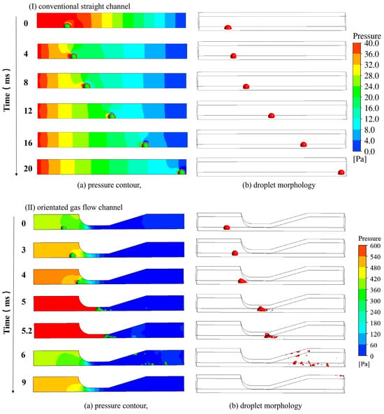
Figure 6 compares the pressure contour of the liquid water transport process in the straight channel with that of the orientated gas flow channel. In the straight channel, the droplet maintains an intact shape and moves on the GDL surface along the flow channel. In addition, except for the relatively large pressure fluctuation around the droplet, the pressure in other parts of the channel is relatively stable. However, for the orientated-type channel, when the droplet flows through the baffle, it directly contacts the upper wall surface of the baffle and blocks the gas flow in the channel, causing a sudden increase in pressure. At the same time, larger vortexes are formed after the droplets. As a result, the liquid water droplet is pushed downwards by the gas flow in the narrow region of the baffle, resulting in droplet rupture and breaking into multiple smaller droplets in the expanding section of the channel. It can also be observed that some liquids adhere to the upper wall of the flow channel due to the absorptive effect of the hydrophilic surface [27]. Additionally, the droplets break up and form the droplet or film with a smaller size and distribute them on the surface of GDL by the gas flow. Notably, in the orientated gas flow channel, frequent phenomena of coalescence and dispersion occur, which can be attributed to the combined effects of the gas flow, the hydrophobic nature of the GDL surface, and the surface tension of the droplet itself [54]. This also corresponds to the fluctuations in the water coverage ratio as displayed in Figure 5.
Figure 6.
The variation in (a) pressure contour and (b) water droplet morphology in two different gas flow channels, (I) conventional straight channel and (II) orientated gas flow channel (droplet radius = 0.25 mm, the average air velocity = 5 ms−1).
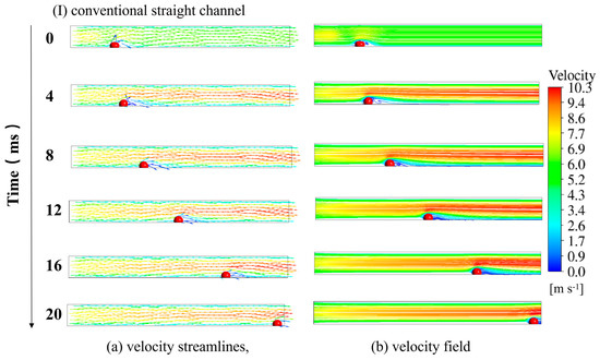
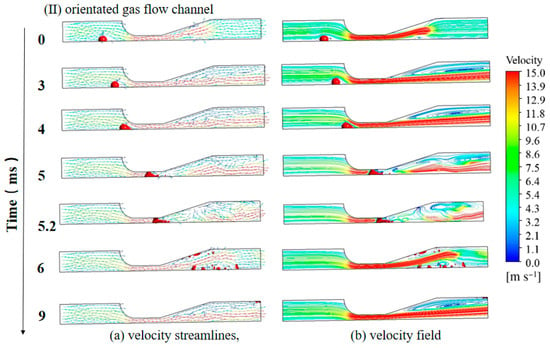
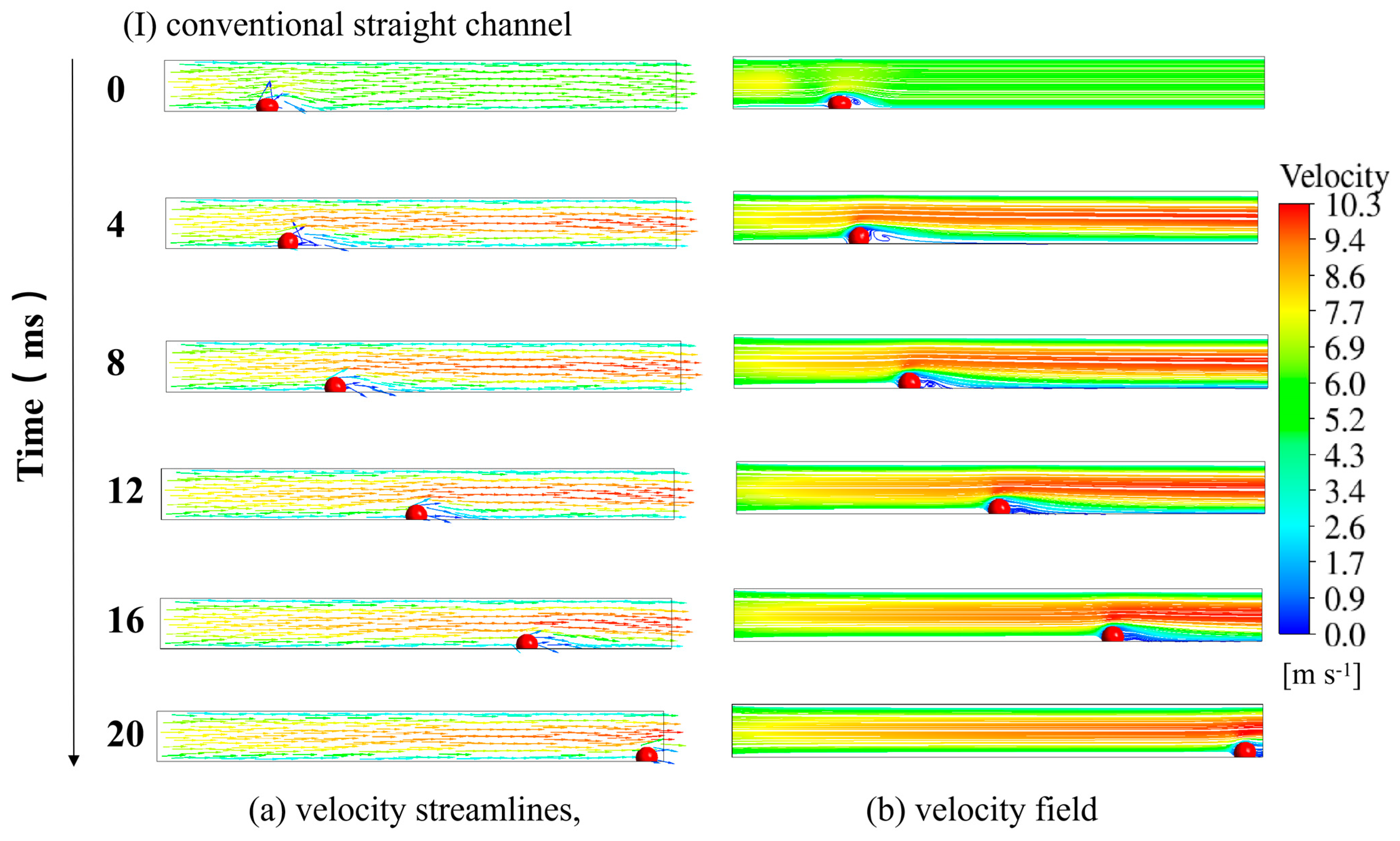
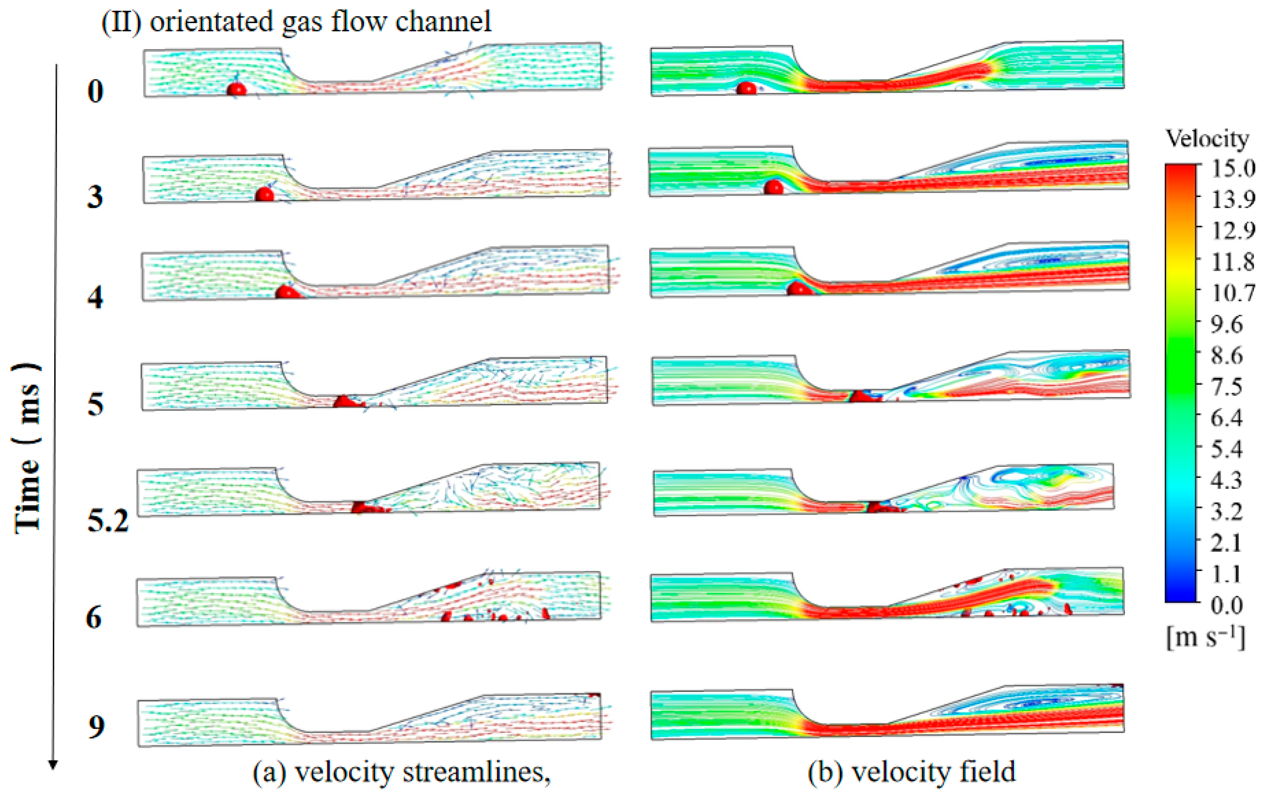
Figure 7 illustrates the velocity streamlines and velocity field on the x-y plane (z = 0.5 mm) of the (a) straight channel and (b) orientated gas flow channel during the water droplet removal process. The gas velocity distribution exhibits a parabolic profile in the straight channel with a maximum speed of around 10 m/s. In contrast, the gas velocity can increase to over 20 m/s after passing through the baffle in the orientated gas flow channel. In both straight channel and orientated gas flow channels, the gas flow field is changed by the gas–liquid interaction. At the same time, there are larger vortexes in the later section after the baffle in the OGFCs, which makes the gas flow more complicated. Affected by the liquid water, the gas velocity in the gas flow direction is accelerated after the droplet. In particular, the presence of the baffle enhances the local air velocity and disturbs the airflow within the channel. Particularly, when the droplet moves across the baffle, vortices with different scales are formed in the gas flow after passing through the baffle. Moreover, the flow direction of the gaseous flow in the orientated gas flow channel is altered, which induces airflow in the direction perpendicular to the GDL surface. This induced gas flow can facilitate the supply of reactant species to the electrochemical reaction sites in CLs. The increase in pressure enhances the gas velocity and leads to a significant deformation of the water droplets when the droplet passes through the narrow space of the baffles. As a result, the acceleration and droplet breakup facilitated by the baffle in the orientated flow type channel significantly enhances the removal of liquid water from the GDL surfaces [53].
Figure 7.
(a) Velocity streamlines and (b) velocity field within the orientated gas flow channel and straight channel. (I) Conventional straight channel, (II) orientated gas flow channel.
3.2. Effects of Droplet Size
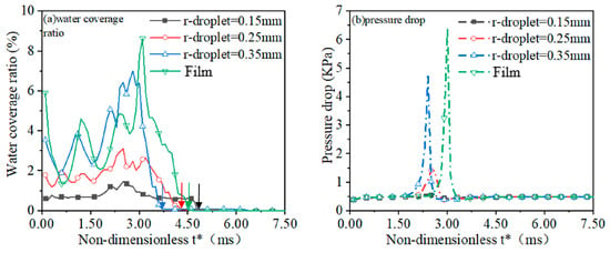
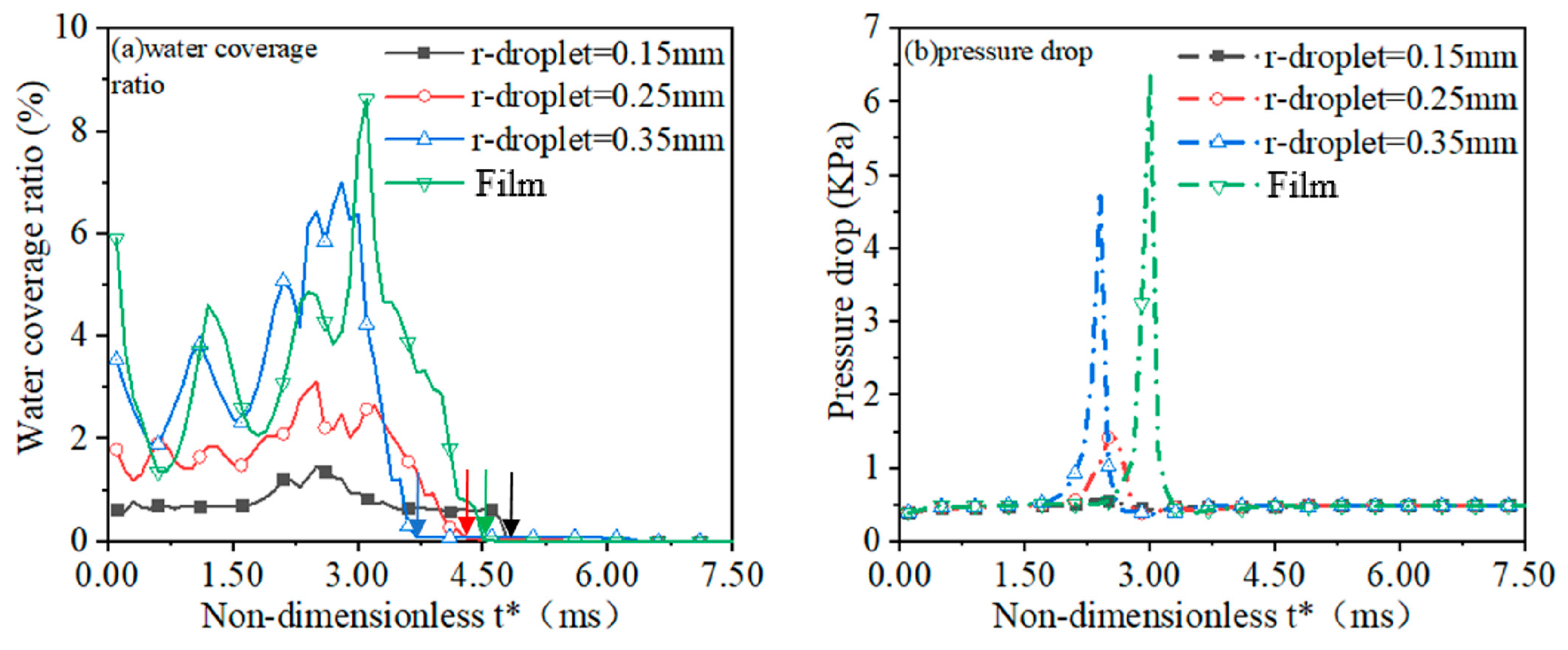
The position of water generated from the pores of GDL is random, and droplets of different sizes may be produced [55]. It is necessary to assess the effects of the droplet size on the removal dynamics of liquid droplets in OGFCs. Figure 8 compares the changes in the liquid water coverage ratio on the GDL surface over time and the pressure drop between the inlet and outlet of the channel for various droplet sizes and liquid film. As shown in Figure 8a, increasing the radius of the droplets will notably increase the coverage area of liquid water on the surface of the GDL, as the water content expands for a larger droplet radius. The maximum water coverage ratio can be increased from 1.72% to 7.01% when the radius of droplets increases from 0.15 mm to 0.35 mm. Particularly, when the morphology of water is liquid film, the coverage ratio changes drastically in the middle stage of the removal process, which is related to the severe liquid deformation and fragmentation caused by the baffle. The order of liquid water discharge time is droplets (r_droplet = 0.35 mm) < droplet (r_droplet = 0.25 mm) < liquid film < droplet (r_droplet = 0.15 mm). The discharge time of liquid droplets is reduced with the increase in droplet size and the time is reduced by 25.53% with the radius of the droplets increased from 0.15 mm to 0.35 mm. It should also be mentioned that when the morphology of liquid water droplet becomes liquid film, the water coverage ratio increases substantially, and the maximum water coverage ratio can be over 8%. This means that the change in morphology into liquid film would lead to a more serious deterioration of the performance of PEMFCs.
Figure 8.
A comparison of gas-liquid transportation for different radius droplets and liquid film in the OGFCs. (a) the liquid water coverage ratio on the GDL surface (b) the pressure drop between the inlet and outlet.
Figure 8b compares the pressure drop between the inlet and outlet of the orientated gas flow channel with different droplet sizes. When the droplets pass through the narrow region near the baffle, an instant and substantial increase in the pressure drop can be observed, followed by a plunge of the pressure drop after the droplets pass through the baffle. Larger droplets will lead to a higher-pressure drop and the maximum pressure drop is 0.58 kPa, 1.5 kPa and 4.6 kPa for the droplets with a radius of 0.15 mm, 0.25 mm and 0.35 mm, respectively. The pressure drop caused by the liquid water film is higher than that of liquid water droplets, and a pressure drop of 6.4 kPa can be observed for the liquid water film. It can be observed that the time instant of the peak pressure for liquid water film is later than that of liquid water droplets, which indicates that it is more difficult to remove the liquid water in the gas flow channel once the morphology changes into liquid film.
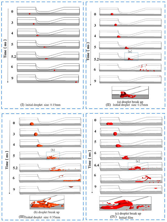
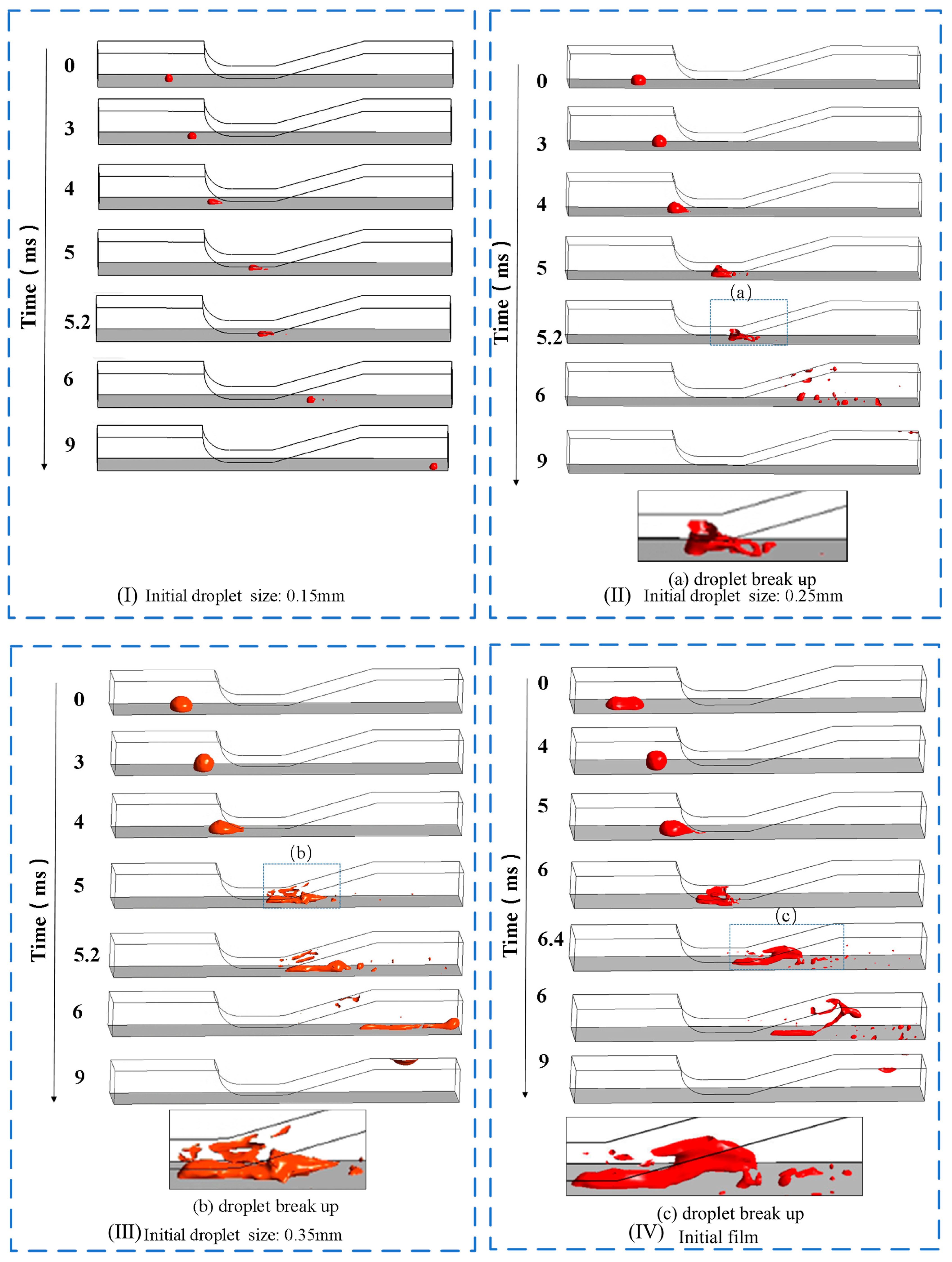
Figure 9 presents the transport and removal process of liquid water droplets in an orientated gas flow channel with various droplet sizes. When the droplet radius is small (r_droplet = 0.15 mm), the shape of the liquid water droplet maintains when the droplet passes through the baffle. Conversely, for larger droplets (r_droplet = 0.25 and 0.35 mm), a significant deformation of their shape can be observed when the droplets encounter the surface of the baffle. Moreover, big droplets can disperse into several smaller droplets after passing through the narrow region of the baffles. This is because the baffle changes the hydraulic radius of the gas flow channel, which leads to a complex vortex motion of the airflow. As the radius of the liquid droplets increases, the droplets can significantly hinder the flow of air when passing through narrow slits, which further reduces the effective cross-sectional area of the gas flow channel and accelerate the air flows. Additionally, the force exerted on the droplets is enhanced, which deforms the shape more significantly and eventually leads to the breakdown of the large droplets. It can also be seen that the shape of the liquid water film changes from a regular cuboid to a big droplet due to the surface tension of the liquid water droplets and the hydrophobicity of the GDL surfaces. The big droplet eventually encounters the orientated baffle and breaks into small droplets. This further illustrates that an orientated baffle can facilitate the removal of liquid water from the GDL surface with different droplet sizes in the channel, but it needs to bear greater pump power loss [37].
Figure 9.
Water transport and removal process of liquid water droplets in orientated gas flow channel with various droplet sizes: (I) r_droplet = 0.15 mm, (II) r_droplet = 0.25 mm, (III) r_droplet = 0.35 mm, (IV) r_droplet = liquid water film.
3.3. Effects of Baffle Geometry
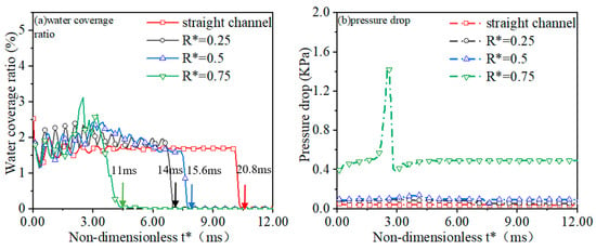
The effects of the geometrical parameters including the baffle height (R), middle baffle length (L1) and sloped leeward side length (L2) on the transport characteristics of liquid water in the orientated gas flow channel are studied in the current study. Figure 10 illustrates the liquid water coverage ratio on the GDL surface, and the pressure drop between the inlet and outlet of the gas flow channel during the transient removal process of liquid water droplets, with the non-dimensional height of the baffles (R*) varying from 0.25 to 0.75. Although the impact of varying baffle height on the water coverage ratio on GDL surfaces is minor, increasing the baffle height would reduce the time needed for the removal of droplets. The order of flow channels with different R values according to the discharge time is as follows: straight channel > orientated channel (R* = 0.5) > orientated channel (R* = 0.25) > orientated channel (R* = 0.75). This can be explained by the fact that at high baffle height, droplets tend to block a substantial portion of the gas flow channels when they encounter the baffles. More blockage accelerates the gas velocity; as a result, the pressure drop across the inlet and outlet of the flow channel rises sharply, contributing to the faster removal of droplets from the GDL surfaces. Figure 10b displays that the pressure drop between the inlet and outlet of the flow channel increases with the rising of baffle height. This can be attributed to the reduction in the gas flow cross-section caused by higher baffles, which leads to an increase in flow resistance and more blockage of the flow pathway. Thus, increasing the baffle height enhances the apparent flow velocity of both the gas and droplets, thereby improving the mass transfer efficiency of the reactant gas and accelerating the drainage rate of liquid water. However, excessively high baffles increase the flow resistance in the channels, resulting in higher pumping power required for gas supplements [40].
Figure 10.
A comparison of gas-liquid transportation for different baffle height R* in the OGFCs. (a) the GDL surface water coverage ratio, (b) the pressure drop between the inlet and outlet.
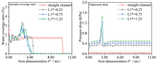
Figure 11a,b illustrate the variation in water coverage ratio on the GDL surface and pressure drop of the orientated gas flow channel when the non-dimensional middle length, L1*, varies from 0.25 to 1.25. Regardless of the size of L1*, the drainage time of the orientated channel is much shorter than that of a conventional straight gas flow channel. With the increase in L1* from 0.25 to 0.75, the drainage time decreases slightly; however, for L1* increasing from 0.75 to 1.25, the drainage time remains almost the same. As shown in Figure 11b, increasing L1* would lead to an increase in the pressure drop between the inlet and outlet, and a higher peak of pressure drop can be observed for longer L1*. This is because the elongation of the slot length is caused by the increase in middle baffle length, which subsequently results in a notable increase in the pressure drop when droplets flow through this slot region. Furthermore, for the non-dimensional middle length of 1.25, the water coverage ratio significantly enlarges after the droplets pass through the baffle. This can be explained by the fact that the high-speed air encountered at the baffle breaks into some tiny droplets.
Figure 11.
A comparison of gas liquid transportation for different L1* in OGFCs. (a) the GDL surface water coverage ratio, (b) the pressure drop between the inlet and outlet.
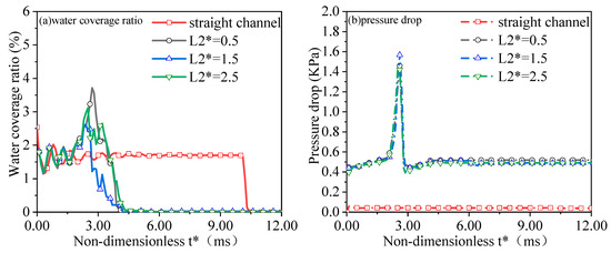
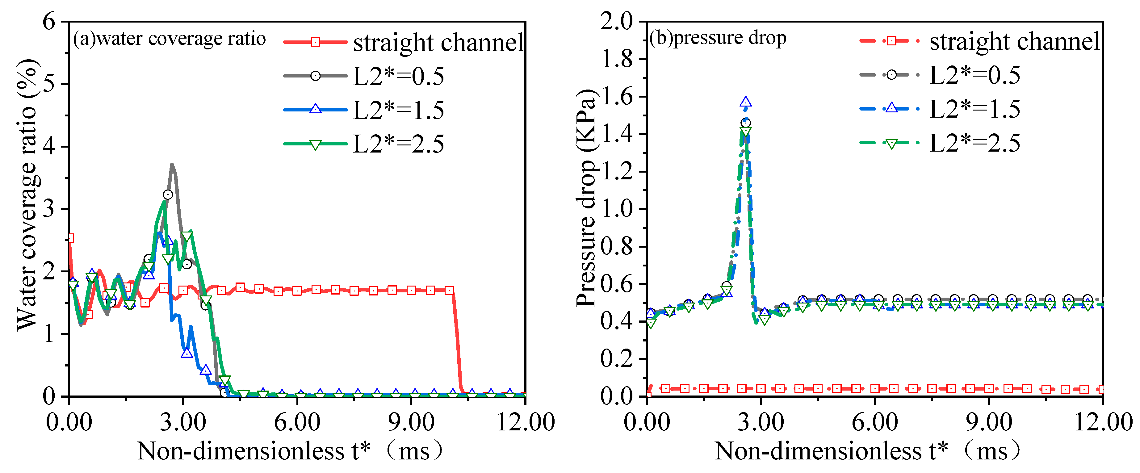
Figure 12 illustrates the liquid water coverage ratio and pressure drop of the gas flow channel when the leeward length, L2*, varies from 0.5 to 2.5. Varying the leeward length can slightly influence the water discharge time. The water discharge time is 8.4 ms, 8.2 ms and 11 ms for the leeward length, L2*, of 0.5, 1.5 and 2.5, respectively. Moreover, the liquid water coverage with a non-dimensional leeward length of 1.5 has the shortest discharge time, because the appropriate length can effectively reduce the formation of vortex and turbulence. This enhanced stability promotes quicker evacuation of liquid water from the gas flow channel. As shown in Figure 12b, for different leeward lengths, L2* = 0.5, 1.5 and 2.5, the trends of pressure drop with time are similar. As L2* increases, the pressure drop increases slightly at first, followed by a quick decrease. The pressure drop is minimal for long leeward length (L2* = 2.5), which stems from the fact that enhanced inclination of the baffle minimizes the formation of vorticity and the local flow losses [34].
Figure 12.
A comparison gas liquid transportation for different L2* in OGFCs. (a) the GDL surface water coverage ratio, (b) the pressure drop between the inlet and outlet.
4. Conclusions
The understanding of the transient removal dynamics of liquid water in the gas flow channels is critical for the design and optimization of the bipolar plate of PEMFCs, which can directly determine the performance of PEMFCs, particularly at their high load operating conditions. A multi-phase model based on the framework of the volume of fluid method is developed in the current study to characterize the removal dynamics of liquid water droplets and films in the OGFCs. Moreover, the impacts of the size of liquid water droplets and the geometrical parameters of the baffles on the removal process of liquid water are examined. The major conclusions of this study are shown as follows.
- The orientated gas flow channel can facilitate the removal process of the liquid droplets, and the discharge time of OGFCs can be reduced by 73.6% compared to that of conventional straight channels.
- The morphology of water is altered by the high velocity of gaseous flow in the orientated gas flow channel. Big droplets can break up into several smaller droplets and distribute on the surface of GDL by the gas flow; the shape of the liquid water film changes from a regular cuboid to a big droplet due to the surface tension of the liquid water droplets and hydrophobic of the GDL surfaces.
- The pressure drop caused by the liquid water film is higher than that of liquid water droplets, and the time instant of the peak pressure for liquid water film is later than that of liquid water droplets.
- Although the impact of varying baffle height on the water coverage ratio on GDL surfaces is minor, increasing the baffle height would reduce the time needed for the removal of droplets.
- With the increase in L1* from 0.25 to 0.75, the drainage time decreases slightly; however, for L1* increasing from 0.75 to 1.25, the drainage time remains almost the same. The impacts of different leeward lengths, L2*, on the water coverage ratio and pressure drop are minor.
Author Contributions
Conceptualization, D.W.; methodology, H.D. and Z.G.; software, X.C.; validation, S.Y., P.S. and W.D.; formal analysis, S.Y.; investigation, D.W., S.Y. and X.C.; data curation, X.C.; writing—original draft preparation, X.C.; writing—review and editing, S.Y.; visualization, X.C.; supervision, D.W., P.S. and X.S.; project administration, D.W. and H.D.; funding acquisition, D.W.; Resources, P.S., H.D., Z.G., W.D. and X.S. All authors have read and agreed to the published version of the manuscript.
Funding
This research was funded by the open fund project (general type) of State Key Laboratory of Advanced Vehicle Integration and Control of China FAW group Co., Ltd. under Grant No. GF-2024-02705; the Scientific and Technological Developing Scheme of Jilin Province under Grant No. 20230101114JC.
Data Availability Statement
The data may be available after request from corresponding authors.
Conflicts of Interest
Authors Dan Wang and Xia Sheng were employed by the China FAW Group Co., Ltd. The remaining authors declare that the research was conducted in the absence of any commercial or financial relationships that could be construed as a potential conflict of interest.
Nomenclature
The following abbreviations are used in this manuscript:
| Symbol | |
| R | baffle height (mm) |
| L1 | baffle length (mm) |
| L2 | length of the Sloped leeward side baffle (mm) |
| R_droplet | radius of droplet (mm) |
| channel length (mm) | |
| channel weight (mm) | |
| channel height (mm) | |
| Re | Reynolds number |
| Volume fraction | |
| Vi | Volume of the phase |
| Pressure (Pa) | |
| Pressure drop between gas inlet and gas outlet (Pa) | |
| Density (kg m−3) | |
| ) | |
| ) | |
| g | ) |
| ) | |
| ) | |
| Time (s) | |
| Contact angle () | |
| ) | |
| the area of the channel inlet | |
| pumping efficiency | |
| parasitic power consumption | |
| PEMFC | polymer electrolyte fuel cells |
| GDL | gas diffusion layer |
| VOF | volume of fluid |
| CLs | catalyst layers |
| ORR | oxygen reduction reaction |
| GFCs | gas flow channels |
| OGFCs | orientated gas flow channels |
| LBM | lattice Boltzmann method |
| RMSE | root mean square error |
| Subscripts | |
| 1 | Gas phase |
| 2 | Liquid phase |
| x, y, z | Coordinate system |
References
- Zhao, C.; Ju, S.; Xue, Y.; Ren, T.; Ji, Y.; Chen, X. China’s energy transitions for carbon neutrality: Challenges and opportunities. Carbon Neutrality 2022, 1, 7. [Google Scholar] [CrossRef] [Scilit]
- Zhang, L.; Harnefors, L.; Nee, H.P. Power-synchronization control of grid-connected voltage-source converters. IEEE Trans. Power Syst. 2009, 25, 809–820. [Google Scholar] [CrossRef] [Scilit]
- Wang, C.; Wei, Y.; Gao, L. A flexible hydrogen-electricity coproduction system through the decoupling of units with different dynamic characteristics. Carbon Neutrality 2023, 2, 4. [Google Scholar] [CrossRef] [Scilit]
- Zheng, Y.; Ma, M.; Shao, H. Recent advances in efficient and scalable solar hydrogen production through water splitting. Carbon Neutrality 2023, 2, 23. [Google Scholar] [CrossRef] [Scilit]
- Aneke, M.; Wang, M. Energy storage technologies and real-life applications—A state of the art review. Appl. Energy 2016, 179, 350–377. [Google Scholar] [CrossRef] [Scilit]
- Bai, F.; Lei, L.; Zhang, Z.; Chen, L.; Chen, L.; Tao, W.Q. Application of similarity theory in the study of proton exchange membrane fuel cells: A comprehensive review of recent developments and future research requirements. Energy Storage Sav. 2022, 1, 3–21. [Google Scholar] [CrossRef] [Scilit]
- Hou, M.; Yi, B.L. Progress and perspective of fuel cell technology. J. Electrochem. 2012, 18, 1. [Google Scholar] [CrossRef] [Scilit]
- Jeong, K.S.; Oh, B.S. Fuel economy and life-cycle cost analysis of a fuel cell hybrid vehicle. J. Power Sources 2002, 105, 58–65. [Google Scholar] [CrossRef] [Scilit]
- Li, Z.; Wang, S.; Li, W.; Zhu, T.; Fan, Z.; Xie, X. Droplet dynamics in a proton exchange membrane fuel cell flow field design with 3D geometry. Int. J. Hydrogen Energy 2021, 46, 16693–16707. [Google Scholar] [CrossRef] [Scilit]
- Wang, Y.; Diaz, D.F.R.; Chen, K.S.; Wang, Z.; Adroher, X.C. Materials, technological status, and fundamentals of PEM fuel cells—A review. Mater. Today 2020, 32, 178–203. [Google Scholar] [CrossRef] [Scilit]
- Wilberforce, T.; El Hassan, Z.; Ogungbemi, E.; Ijaodola, O.; Khatib, F.; Durrant, A.; Thompson, J.; Baroutaji, A.; Olabi, A. A comprehensive study of the effect of bipolar plate (BP) geometry design on the performance of proton exchange membrane (PEM) fuel cells. Renew. Sustain. Energy Rev. 2019, 111, 236–260. [Google Scholar] [CrossRef] [Scilit]
- Manso, A.P.; Marzo, F.F.; Barranco, J.; Garikano, X.; Garmendia, M.M. Influence of geometric parameters of the flow fields on the performance of a PEM fuel cell. A review. Int. J. Hydrogen Energy 2012, 37, 15256–15287. [Google Scholar] [CrossRef] [Scilit]
- Wang, J. Theory and practice of flow field designs for fuel cell scaling-up: A critical review. Appl. Energy 2015, 157, 640–663. [Google Scholar] [CrossRef] [Scilit]
- Scholta, J.; Escher, G.; Zhang, W.; Küppers, L.; Jörissen, L.; Lehnert, W. Investigation on the influence of channel geometries on PEMFC performance. J. Power Sources 2006, 155, 66–71. [Google Scholar] [CrossRef] [Scilit]
- Chowdhury, M.Z.; Genc, O.; Toros, S. Numerical optimization of channel to land width ratio for PEM fuel cell. Int. J. Hydrogen Energy 2018, 43, 10798–10809. [Google Scholar] [CrossRef] [Scilit]
- Manoj, K.P.; Kolar, A.K. Effect of cathode channel dimensions on the performance of an air-breathing PEM fuel cell. Int. J. Therm. Sci. 2010, 49, 844–857. [Google Scholar] [CrossRef] [Scilit]
- Zhan, Z.; Wang, C.; Fu, W.; Pan, M. Visualization of water transport in a transparent PEMFC. Int. J. Hydrogen Energy 2012, 37, 1094–1105. [Google Scholar] [CrossRef] [Scilit]
- Mojica, F.; Rahman, A.; Sarker, M.; Hussey, D.S.; Jacobson, D.L.; LaManna, J.M.; Chuang, P.-Y.A. Study of converging-diverging channel induced convective mass transport in a proton exchange membrane fuel cell. Energy Convers. Manag. 2021, 237, 114095. [Google Scholar] [CrossRef] [Scilit]
- Wang, Y.; Basu, S.; Wang, C.-Y. Modeling two-phase flow in PEM fuel cell channels. J. Power Sources 2008, 179, 603–617. [Google Scholar] [CrossRef] [Scilit]
- Ding, Y.; Bi, X.; Wilkinson, D.P. 3D simulations of the impact of two-phase flow on PEM fuel cell performance. Chem. Eng. Sci. 2013, 100, 445–455. [Google Scholar] [CrossRef] [Scilit]
- Ding, Y.; Bi, X.T.; Wilkinson, D.P. Numerical investigation of the impact of two-phase flow maldistribution on PEM fuel cell performance. Int. J. Hydrogen Energy 2014, 39, 469–480. [Google Scholar] [CrossRef] [Scilit]
- Hiroki, N.; Toshiyuki, M.; Tetsuya, O. Impedance analysis of the effect of flooding in the cathode catalyst layer of the polymer electrolyte fuel cell. Electrochim. Acta 2013, 113, 720–729. [Google Scholar]
- Wang, X.K.; Chen, S.T.; Fan, Z.H.; Li, W.W.; Wang, S.B.; Li, X.; Zhao, Y.; Zhu, T.; Xie, X.F. Laser-perforated gas diffusion layer for promoting liquid water transport in a proton exchange membrane fuel cell. Int. J. Hydrogen Energy 2017, 42, 29995–30003. [Google Scholar] [CrossRef] [Scilit]
- Kim, M.; Jung, N.; Eom, K.S.; Yoo, S.J.; Kim, J.Y.; Jang, J.H.; Kim, H.J.; Hong, B.K.; Cho, E.A. Effects of anode flooding on the performance degradation of polymer electrolyte membrane fuel cells. J. Power Sources 2014, 266, 332–340. [Google Scholar] [CrossRef] [Scilit]
- Hussaini, I.S.; Wang, C.Y. Visualization and quantification of cathode channel flooding in PEM fuel cells. J. Power Sources 2009, 187, 444–451. [Google Scholar] [CrossRef] [Scilit]
- Ji, M.; Wei, Z. A Review of Water Management in Polymer Electrolyte Membrane Fuel Cells. Energies 2009, 2, 1057. [Google Scholar] [CrossRef] [Scilit]
- Liu, H.; Tan, J.; Cheng, L.; Yang, W. Enhanced water removal performance of a slope turn in the serpentine flow channel for proton exchange membrane fuel cells. Energy Convers. Manag. 2018, 176, 227–235. [Google Scholar] [CrossRef] [Scilit]
- Qin, Y.; Du, Q.; Yin, Y.; Jiao, K.; Li, X. Numerical investigation of water dynamics in a novel proton exchange membrane fuel cell flow channel. J. Power Sources 2013, 222, 150–160. [Google Scholar] [CrossRef] [Scilit]
- Liao, P.; Yang, D.; Xu, S.; Li, B.; Ming, P.; Li, Z.; Zhou, X. Effect of three-dimensional geometric structure and surface wettability on two-phase flow behavior in a proton exchange membrane fuel cell gas flow channel: Modeling and simulation. Int. J. Hydrogen Energy 2024, 50, 1183–1199. [Google Scholar]
- Guo, Q.; Qin, Y. Numerical investigation of water droplet removal characteristics in novel block channels of PEMFC using dynamic wettability model. Int. J. Hydrogen Energy 2021, 46, 36890–36902. [Google Scholar] [CrossRef] [Scilit]
- Yang, G.; Meng, K.; Deng, Q.; Chen, W.; Chen, B. Numerical investigation and experimental verification of liquid water dynamic transfer characteristics in the flow field of PEMFC with dead-ended anode during gas purging. Chem. Eng. J. 2024, 491, 152082. [Google Scholar] [CrossRef] [Scilit]
- Ebrahimzadeh, A.A.; Khazaee, I.; Fasihfar, A. Experimental and numerical investigation of obstacle effect on the performance of PEM fuel cell. Int. J. Heat Mass Transf. 2019, 141, 891–904. [Google Scholar] [CrossRef] [Scilit]
- Yin, Y.; Wang, X.; Shangguan, X.; Zhang, J.; Qin, Y. Numerical investigation on the characteristics of mass transport and performance of PEMFC with baffle plates installed in the flow channel. Int. J. Hydrogen Energy 2018, 43, 8048–8062. [Google Scholar] [CrossRef] [Scilit]
- Guo, H.; Chen, H.; Ye, F.; Ma, C.F. Baffle shape effects on mass transfer and power loss of proton exchange membrane fuel cells with different baffled flow channels. Int. J. Energy Res. 2019, 43, 2737–2755. [Google Scholar] [CrossRef] [Scilit]
- Chen, H.; Guo, H.; Ye, F.; Ma, C.F. Modification of the two-fluid model and experimental study of proton exchange membrane fuel cells with baffled flow channels. Energy Convers. Manag. 2019, 195, 972–988. [Google Scholar] [CrossRef] [Scilit]
- Chen, H.; Guo, H.; Ye, F.; Ma, C.F. A numerical study on convection and diffusion of mass transfer in proton exchange membrane fuel cell with orientated-type flow channels. Int. J. Energy Res. 2020, 45, 5659–5678. [Google Scholar] [CrossRef] [Scilit]
- Chen, H.; Guo, H.; Ye, F.; Ma, C.F. An experimental study of cell performance and pressure drop of proton exchange membrane fuel cells with baffled flow channels. J. Power Sources 2020, 472, 228456. [Google Scholar] [CrossRef] [Scilit]
- Sun, P.; Cheng, X.; Yang, S.; Dou, H.; Guo, Z.; Sheng, X.; Wang, D. Flow characteristics and optimization of the orientated gas flow channels of proton exchange membrane fuel cells. Case Stud. Therm. Eng. 2025, 76, 107472. [Google Scholar] [CrossRef] [Scilit]
- Chen, H.; Guo, H.; Ye, F.; Ma, C.F.; Liao, Q.; Zhu, X. Mass transfer in proton exchange membrane fuel cells with baffled flow channels and a porous-blocked baffled flow channel design. Int. J. Energy Res. 2019, 43, 2910–2929. [Google Scholar]
- Chen, H.; Guo, H.; Ye, F.; Ma, C.F. Experimental investigations on cell performance of proton exchange membrane fuel cells with orientated-type flow channels. J. Energy Eng. 2020, 146, 04020062. [Google Scholar] [CrossRef] [Scilit]
- Chen, H.; Guo, H.; Ye, F.; Ma, C.F. A numerical study of baffle height and location effects on mass transfer of proton exchange membrane fuel cells with orientated-type flow channels. Int. J. Hydrogen Energy 2021, 46, 7528–7545. [Google Scholar] [CrossRef] [Scilit]
- Le, A.D.; Zhou, B. A general model of proton exchange membrane fuel cell. J. Power Sources 2008, 182, 197–222. [Google Scholar] [CrossRef] [Scilit]
- Ferreira, R.B.; Falcao, D.S.; Oliveira, V.B.; Pinto, A.M.F.R. Numerical simulations of two-phase flow in proton exchange membrane fuel cells using the volume of fluid methodea review. J. Power Sources 2015, 277, 329–342. [Google Scholar] [CrossRef] [Scilit]
- Carton, J.G.; Lawlor, V.; Olabi, A.G.; Hochenauer, C.; Zauner, G. Water droplet accumulation and motion in PEM (Proton Exchange Membrane) fuel cell mini-channels. Energy 2012, 39, 63–73. [Google Scholar] [CrossRef] [Scilit]
- Shah, A.A.; Luo, K.H.; Ralph, T.R.; Walsh, F.C. Recent trends and developments in polymer electrolyte membrane fuel cell modeling. Electrochim. Acta 2011, 56, 3731–3757. [Google Scholar] [CrossRef] [Scilit]
- Gopalan, P.; Kandlikar, S.G. Effect of channel materials and trapezoidal corner angles on emerging droplet behavior in Proton Exchange Membrane Fuel Cell gas channels. J. Power Sources 2014, 248, 230–238. [Google Scholar] [CrossRef] [Scilit]
- Dang, D.K.; Zhou, B. Enhanced water management in PEMFC cathode using streamlined baffles. J. Power Sources 2024, 623, 235475. [Google Scholar] [CrossRef] [Scilit]
- ANSYS Inc. ANSYS FLUENT Theory Guide Release 15.0; ANSYS Inc.: Canonsburg, PA, USA, 2013. [Google Scholar]
- Mortazavi, M.; Heidari, M.; Niknam, S.A. A Discussion About Two-Phase Flow Pressure Drop in Proton Exchange Membrane Fuel Cells. Heat Transf. Eng. 2020, 41, 1784–1799. [Google Scholar]
- Yan, F.; Su, Y.; Lu, H.; Feng, S.; Qin, H. Optimization of fuel cell bio-inspired bird belly-shaped obstacle flow channel structure through back-propagation neural network model optimized by the particle swarm optimization algorithm. Fuel 2026, 407, 137313. [Google Scholar]
- Li, H.-W.; Liu, J.-N.; Yang, Y.; Fan, W.; Lu, G.-L. Research on mass transport characteristics and net power performance under different flow channel streamlined imitated water-drop block arrangements for proton exchange membrane fuel cell. Energy 2022, 251, 123983. [Google Scholar] [CrossRef] [Scilit]
- Wang, M.; Ding, Y.; Hu, J.; Xu, L.; Yang, X. Numerical simulation of water and heat transport in the cathode channel of a PEM fuel cell. Int. J. Hydrogen Energy 2022, 47, 11007–11027. [Google Scholar] [CrossRef] [Scilit]
- Zhang, X.; Ma, X.; Yang, J.; Zhu, X.; Tai, S.; Shuai, S. Effect of liquid water in flow channel on proton exchange membrane fuel cell: Focusing on flow pattern. Energy Convers. Manag. 2022, 258, 115528. [Google Scholar] [CrossRef] [Scilit]
- Lorenzini-Gutierrez, D.; Kandlikar, S.G.; Hernandez-Guerrero, A.; Elizalde-Blancas, F. Residence time of water film and slug flow features in fuel cell gas channels and their effect on instantaneous area coverage ratio. J. Power Sources 2015, 279, 567–580. [Google Scholar] [CrossRef] [Scilit]
- Wang, X.R.; Ma, Y.; Gao, J.; Li, T.; Jiang, G.Z.; Sun, Z.Y. Review on water management methods for proton exchange membrane fuel cells. Int. J. Hydrogen Energy 2021, 46, 12206–12229. [Google Scholar] [CrossRef] [Scilit]

Disclaimer/Publisher’s Note: The statements, opinions and data contained in all publications are solely those of the individual author(s) and contributor(s) and not of MDPI and/or the editor(s). MDPI and/or the editor(s) disclaim responsibility for any injury to people or property resulting from any ideas, methods, instructions or products referred to in the content. |
© 2026 by the authors. Licensee MDPI, Basel, Switzerland. This article is an open access article distributed under the terms and conditions of the Creative Commons Attribution (CC BY) license.