


Abstract
Low-voltage primary batteries broadly power small electronics used in health, biomedical, and wearable applications. These devices are generally more sensitive to volumetric capacity than gravimetric capacity. The current state-of-the-art button battery is Zn-Ag2O, where contributors that limit volumetric capacity include the incorporation of inactive materials in the electrode microstructure such as gelling agents, binders, and conductive additives. Herein, cathode materials of CuO and FeS2 will be described for small form factor coin/button cells. When paired with Li metal anodes, the operating voltage is similar to Zn-Ag2O. The key innovation is that they will be processed into all-active-material (AAM) electrode architectures, where the electrodes will comprise only electroactive materials and pores that are filled with electrolyte during cell fabrication. The AAM architecture significantly enhanced electroactive material volume utilization, and thus volumetric capacity. FeS2 and CuO were processed into AAM electrodes under various processing conditions, and Li-FeS2 and Li-CuO primary batteries were fabricated and evaluated. At the cell level, volumetric capacity of 1300 mAh cm−3 was achieved, and in a button cell form factor 395/927, nearly 100 mAh was delivered, which compares favorably with commercially available options, which typically range from 27 to 55 mAh.
1. Introduction
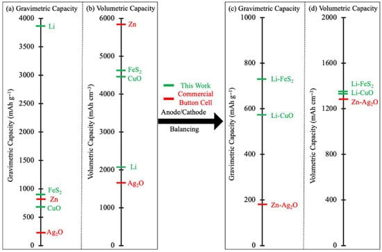
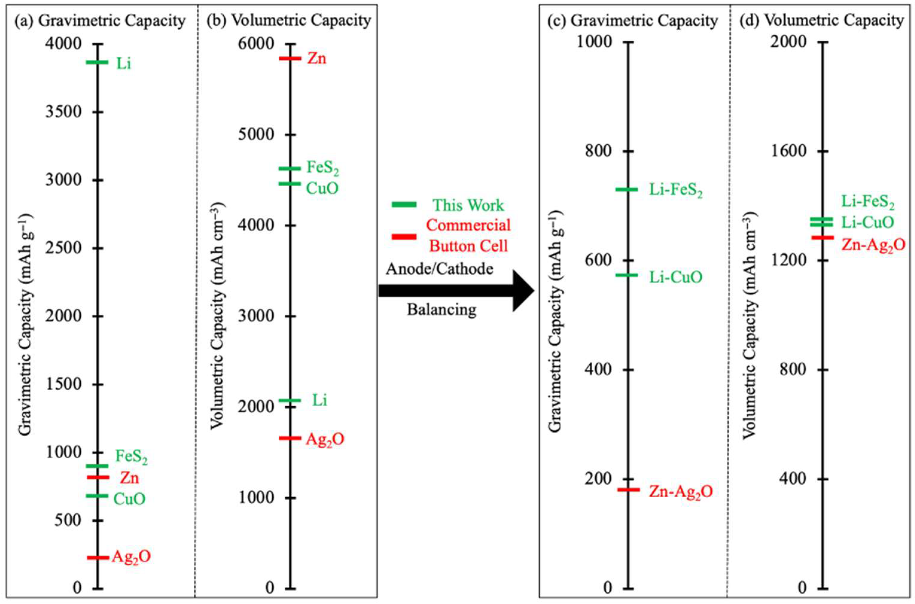
Low-voltage batteries with a nominal voltage of 1.5 V have been widely used in many applications including wearable and health devices [1]. The current state-of-the-art battery, especially in small form factor button cells, is Zn-Ag2O [1]. Zn-Ag2O cells have about 40% higher volumetric capacity, but a much higher cost due to the electroactive materials used, than alternatives such as alkaline batteries (i.e., Zn-MnO2). For Zn-Ag2O cells, the Zn metal anodes have a high theoretical volumetric and gravimetric capacity of 5850 mAh cm−3 and 820 mAh g−1, while the Ag2O cathode material has theoretical volumetric and gravimetric capacities of 1650 mAh cm−3 and 230 mAh g−1, respectively. After cell balancing using the theoretical active material capacities, the theoretical volumetric and gravimetric capacities for the balanced Zn-Ag2O cell active materials are 1280 mAh cm−3 and 180 mAh g−1. CuO and FeS2 have been previously reported and commercialized as cathode materials for primary batteries paired with Li metal [2,3], although they are not typically found in smaller form factor button cells used in many wearable devices. Both materials are produced in large quantities and readily available commercially, where FeS2 naturally exists as pyrite mineral in the earth’s crust with high abundance and extremely low cost [4], and CuO has wide industrial applications [5].
The theoretical volumetric and gravimetric capacities of Li, CuO, and FeS2 are 2060 mAh cm−3, 4310 mAh cm−3, and 4460 mAh cm−3; and 3860 mAh g−1, 670 mAh g−1, and 890 mAh g−1, respectively. For CuO, the complete discharge/lithiation is [6]
2Li + CuO => Cu + Li2O
For FeS2, the complete discharge/lithiation is [7]
4Li + FeS2 => Fe + 2Li2S
After balancing, the theoretical volumetric and gravimetric capacities of Li-CuO and Li-FeS2 are 1390 mAh cm−3, 1410 mAh cm−3, 570 mAh g−1, and 720 mAh g−1, respectively. These theoretical gravimetric and volumetric capacities are benchmarked and illustrated in Figure 1. A key consideration for the selection of these two cathode materials for study was that they have a similar working voltage to the established Zn-Ag2O system/chemistry, but a larger theoretical capacity than a balanced Zn-Ag2O cell. When considering first-row transition metal oxides (later rows were not selected for this work due to generally lower earth abundance and higher cost), most of the materials containing these elements either have much lower operating voltage in the initial discharge (Li-Fe2O3 < 1.1 V [8], Li-Fe3O4 < 1.1 V [9], Li-Cr2O3 < 0.7 V [10], Li-Mn3O4 < 0.7 V [11], Li-Co3O4 < 1.0 V [12], Li-NiO < 0.5 V [13], and Li-ZnO < 0.7 V [14]) or much lower capacity (Li-V2O5 < 400 mAh g−1 [15], Li-TiO2 < 300 mAh g−1 with common phases of anatase, rutile, and brookite [16], and Li-MnO2 < 300 mAh g−1 [17]). The same limitations for primary cells applies to the first-row transition metal sulfides, with Li-TiS2 < 200 mAh g−1 [18], Li-VS2 < 200 mAh g−1 [19], Li-Cr2S3 < 0.8 V [20], Li-MnS < 0.6 V [21], Li-CoS2 < 700 mAh g−1 [22], Li-NiS2 < 800 mAh g−1 [23], Li-CuS < 600 mAh g−1 [24], and Li-ZnS < 0.8 V [25]. It is noted that although Li-NiS2 has only slightly less capacity than Li-FeS2, the cost and abundance are not as attractive. Compared to Zn-Ag2O, the theoretical gravimetric capacity is 320% and 400% more for CuO and FeS2, while the volumetric capacity is only 10% higher. The limited volumetric capacity advantage at the material level is likely a contributor to why Zn-Ag2O has not been replaced by these alternatives. Even though the gravimetric capacity advantage is large, the relevant applications are less sensitive to weight relative to volume in powering wearable and biomedical devices.
Figure 1.
Theoretical (a) gravimetric and (b) volumetric capacity of the individual electrode active materials noted. Theoretical (c) gravimetric and (d) volumetric capacity after balancing electrodes on an active material basis for Zn-Ag2O, Li-FeS2, and Li-CuO.
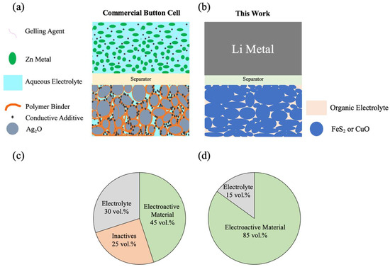
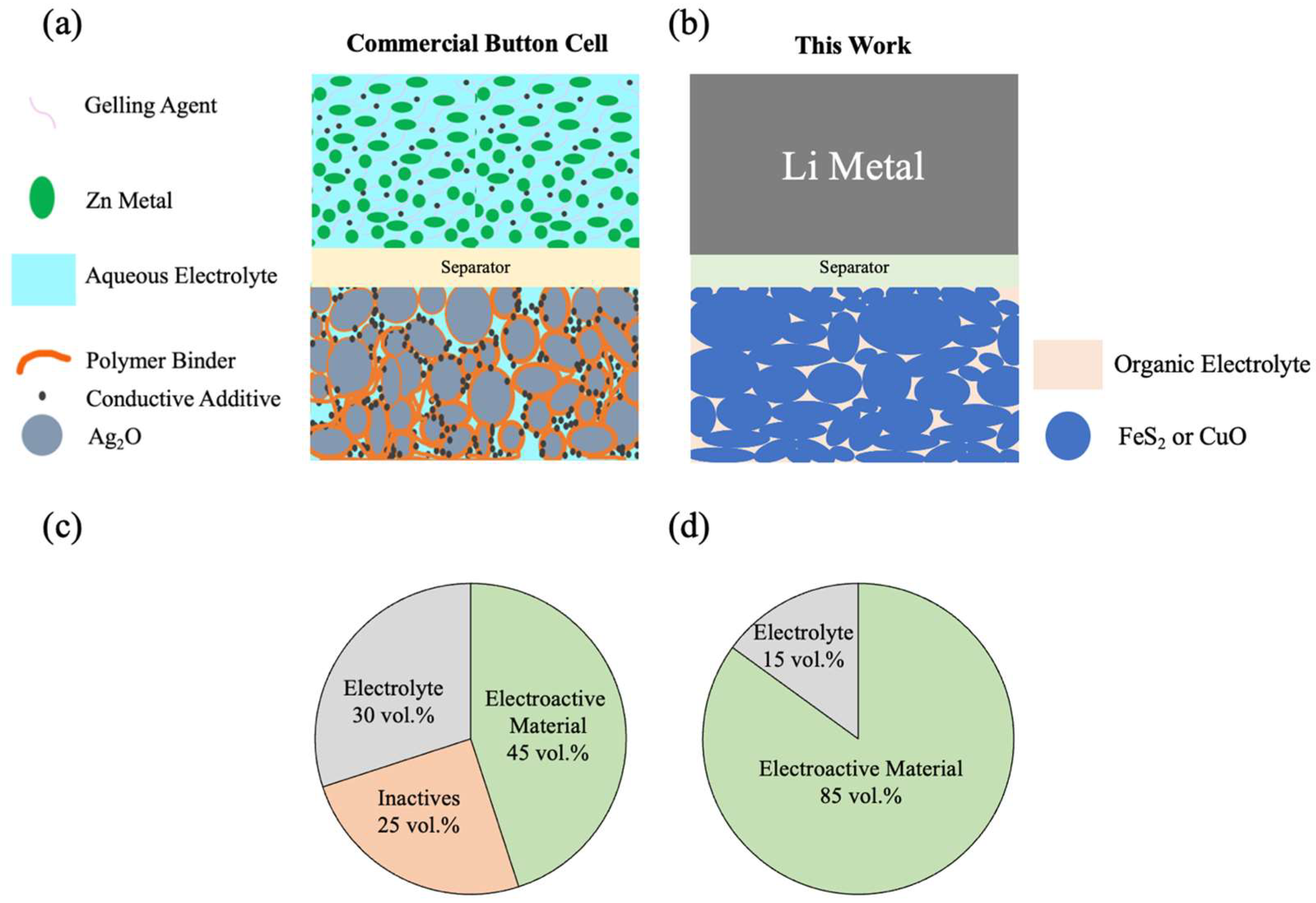
At the cell level, limitations in volume utilization of the electroactive material in the electrode lead to much lower capacity for Zn-Ag2O batteries relative to theoretical values. An illustration demonstrating this design element can be found in the schematic in Figure 2a, where inactive components such as gelling agents, polymer binders, and conductive additives take up large amounts of the cell volume. As an example, according to a previous teardown report [26], the total electrode contained 37.1 wt.% of a SR1120SW/381 button cell from Maxell. According to the data sheet from Maxell, the cell total mass was 1.0 g and capacity was 55 mAh. Assuming the electroactive material delivers 95% of the theoretical gravimetric capacity (180 mAh g−1), the cell capacity would be 63.44 mAh, suggesting the inactives in the electrode would be 13.3 wt.%. Assuming an inactive material density of 2 g cm−3, and given the density of Zn and Ag2O are both 7.1 g cm−3, the inactive materials in the electrode would consume 25 vol.% of the total electrodes, with that volume not including pores that become laden with electrolyte during cell fabrication. Assuming a porosity of 30 vol.%, the electroactive material would only be 45 vol.%, less than half the electrode volume within the cell (summarized in Figure 2c).
Figure 2.
(a,b) Cartoon schematics of electrode regions and (c,d) charts of relative volume fractions in the electrodes for (a,c) conventional Zn-Ag2O button batteries and (b,d) the cells in this report.
Volumetric capacity of batteries is often more critical than gravimetric capacity in applications powering miniature or wearable devices [27]. A broadly effective way to improve cell level volumetric capacity is to improve the electroactive material volume utilization in the electrode. In principle, Li metal electrodes do not need pores and the stripping during discharge of a pore-free Li metal anode could effectively utilize all the anode capacity and volume, if fully stripped. To improve cathode volume utilization, herein we applied an all-active-material (AAM) electrode architecture that was free of inactive additives and only contained pores and the electroactive CuO or FeS2 (schematic shown in Figure 2b). The pore-free anode and removal of inactives significantly increased the electroactive material volume fraction to over 80 vol.% (Figure 2d). The general processing procedures included coating the electroactive material with a sacrificial binder, hydraulic compression, and thermal treatment. The thermal treatment removes the binder, strengthens inter-particle connections to improve mechanical integrity, and in some cases also densifies the electrode. The CuO (10−3–10−2 S cm−1) and FeS2 (10−2–102 S cm−1) materials have intrinsically high electronic conductivity, and as discharge proceeds, the electronic conductivity of these materials increases with lithiation [28,29,30,31]. The electron hopping between particles is facilitated by inter-particle connections; thus, the matrix electronic conductivity was expected to be sufficient from the electroactive material within the electrode itself. The AAM architecture has previously been demonstrated for successful cycling of multiple Li-ion electrode materials, although these were for secondary batteries [32,33,34,35,36,37]. In this work, CuO and FeS2 were processed into AAM electrodes and evaluated as high-capacity primary cells.
2. Materials and Methods
We obtained 200-mesh CuO (>99% purity) from Alfa Aesar, and 325- and 800-mesh size CuO (>99% purity) were obtained from Taixing Smelting Plant. FeS2 with purity of >99% at 325 mesh size (referred to as 99FeS2) was obtained from Sigma (St. Louis, MO, USA), and FeS2 with purity of >95% at 325 mesh size (referred to as 95FeS2) was obtained from Tongling Weite Mining (Tongling, China). Electroactive material powder used in this work is summarized in Supporting Information, Table S1. Mesh sizes of 200, 325, and 800 correspond to maximum particle sizes of 74, 44, and 18 µm, respectively. For conventional composite electrodes, 200-mesh CuO or 99FeS2 was mixed with acetylene carbon black (CB, Alfa Aesar, Heysham, UK), and polyvinyl pyrrolidone (PVP, Sigma Aldrich, St. Louis, MO, USA, 360 kDa molecular weight) using ethanol (Fisher, Waltham, MA, USA) solvent with a weight ratio of 8:1:1 active material:CB:PVP. The slurry was blade coated with a gap width of 200 µm onto an aluminum current collector and dried at 80 °C overnight. The resulting electrode active material loadings for composite electrodes were 2.4 mg cm−2 and 5.0 mg cm−2 for CuO and 99FeS2, respectively.
For AAM electrodes, all powders were first coated with 1.6 wt.% (wt.% indicates amount coating particles after processing and solvent removal) polyvinyl butyral (PVB, Pfaltz & Bauer, Waterbury, CT, USA) by blending in an ethanol suspension with a mortar and pestle by hand. The suspension was blended in a fume hood until it appeared dry to the naked eye. An amount of 0.2 g of PVB-coated CuO was loaded into a circular pellet die with a diameter of 13 mm, and pressed at pressures ranging from 75 to 225 MPa for 5 s. The compressed pellets were transferred to a box furnace and heated to maximum temperatures ranging from 600 to 1100 °C, where the pellets were held at the maximum temperature for 1 hour. The temperature ramp rates for both heating and colling were 2 °C min−1. The resulting CuO AAM electrodes had thicknesses ranging between 340 and 480 µm, diameters ranging between 10.8 and 13 mm, and porosity ranging between 12 and 52 vol% depending on the specific processing conditions. For the higher purity FeS2, 0.15 g of PVB-coated 99FeS2 was loaded into a circular pellet die with diameter of 13 mm and compressed at pressures ranging between 25 and 225 MPa for 5 s. The compressed pellets were transferred to a tube furnace and heated at 500 °C for 1 hour with ramp up and down rates of 2 °C min−1 under Argon atmosphere. The resulting 99FeS2 AAM electrodes had thicknesses ranging between 320 and 370 µm, diameters of ~13 mm, and porosities ranging between 32 and 42 vol%. For lower purity FeS2 pellets, 0.14 g of PVB-coated 95FeS2 was loaded on to a circular pellet die with diameter of 7 mm and compressed at 30 MPa for 5 s. The thermal treatment condition was the same as for the 99FeS2 pellets. The resulting 95FeS2 AAM electrodes had a thickness of 1100 µm, diameter of 7 mm, and porosity of 40 vol%.
The electrodes were transferred to an Argon-filled glove box for battery assembly. A conductive sheet was added between the AAM electrode and current collector to reduce surface contact resistance. The conductive sheet was fabricated in house, and was processed similarly to a conventional composite electrode. An equal weight of CB and PVP in ethanol suspension was prepared and doctor blade coated onto an aluminum foil. The conductive film was dried at 80 °C overnight with film loading of the conductive composite being 1–2 mg cm−2, with a typical value being 1.85 mg cm−2. Total thickness of the conductive sheet (Al and carbon composite) was ~25 μm. The electrolyte was 1.2 M LiPF6 in 1:3 volume ratio ethylene carbonate (EC):ethyl methyl carbonate (EMC) from Gotion (Fremont, CA, USA), referred to as “Gen2”, with Celgard 2325 used as separator. All electrodes were paired with Li metal and evaluated in 2032 format coin cells. Button cells of 395/927 format were also assembled and assessed for AAM cathodes of 95FeS2 with 95% purity.
Powder x-ray diffraction (XRD) patterns were collected using Empyrean (Panalytical, Malvern, UK) equipment. The XRD sample preparation for AAM electrodes included grinding the pellet into powder after they had completed thermal treatment. Optical microscopy was performed using an Olympus (Hachioji, Japan) BX51M. Direct current (DC) conductivity was measured by sandwiching the CuO AAM electrode between 2 conductive sheets followed by applying a constant voltage of 0.1 mV using a Gamry (Warminster, PA, USA) Reference 600. Electrochemical evaluations were conducted using a multichannel battery cycler (MACCOR, Tulsa, OK, USA).
3. Results and Discussion
3.1. CuO
The XRD pattern for the 200-mesh CuO can be found in Supporting Information, Figure S1. The material was consistent with a monoclinic structure and had no observed impurity peaks, consistent with prior reports for CuO [38,39]. The material was then evaluated electrochemically as a cathode active material in a conventional composite cathode paired with a lithium metal anode and Gen2 electrolyte. The cell was slowly discharged at a current density of 0.08 mA cm−2 (~C/20), and the discharge voltage profile can be found in Supporting Information, Figure S2. The discharge capacity started to be delivered at ~1.3 V, and the discharge process was allowed to proceed until the cutoff voltage of 0.5 V. The discharge profile for the CuO material was consistent with previous reports of the material paired with Li metal negative electrodes [40,41]. The capacity was 767 mAh g−1 CuO, which exceeded the theoretical capacity of 670 mAh g−1 CuO. It was expected that the capacity exceeding the theoretical capacity was likely due to irreversible carbonate-based electrolyte decomposition processes providing extra capacity [42]. The capacity above the theoretical capacity was all below 0.9 V, with most of this capacity outside the stability window of the electrolyte [42], again consistent with electrolyte decomposition likely being responsible for the excess capacity.
The porosity of AAM CuO electrodes can be modified through controlling the compression pressure, and also the heating temperature after compression. The resulting porosity after compression and thermal treatments can be found in Supporting Information, Figure S3. The porosity decreased as compression pressure and heating temperature increased. Mesh sizes of 200, 325, and 800 correspond to maximum particle sizes of 74, 44, and 18 µm, respectively. As the particle size decreased (i.e., mesh size increased), the porosity also decreased after processing, which was attributed to increased particle surface area facilitating increased densification during thermal treatment. These results highlighted the manufacturing/processing flexibility for the AAM electrodes with regard to targeting different cell geometries or higher energy vs. power density (where lower porosity will, in general, increase energy density at the expense of power density). XRD was conducted on the CuO pellet using 200-mesh powder compressed to 225 MPa and heated to 950 °C, and the resulting pattern can be found in Supporting Information, Figure S1. The pellet was ground by hand with a mortar and pestle to facilitate XRD sample preparation. The XRD pattern for the powder after heat treatment processing compared to the pristine powder had sharper peaks, suggesting the thermal treatment increased the material crystallinity. No impurity peaks were noticed. An optical microscopy image of the surface of the CuO AAM electrode after processing can be found in Supporting Information, Figure S4. Particles were in intimate contact, which was consistent with qualitative observations of maintaining mechanical integrity with handling of the pellets. The DC electronic conductivity of the densified AAM electrode was measured to be 0.0013 S cm−1. This conductivity was within the previously reported range of 10−3–10−2 S cm−1 [28]. Given that the AAM electrode had porosity and additional contact resistance from the measurement configuration, this result suggested the inter-particle connections formed during the compression and thermal treatment were robust and assisted in providing a favorable AAM electrode matrix electronic conductivity.
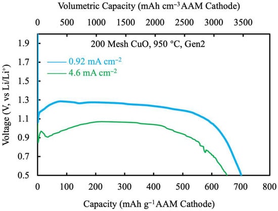
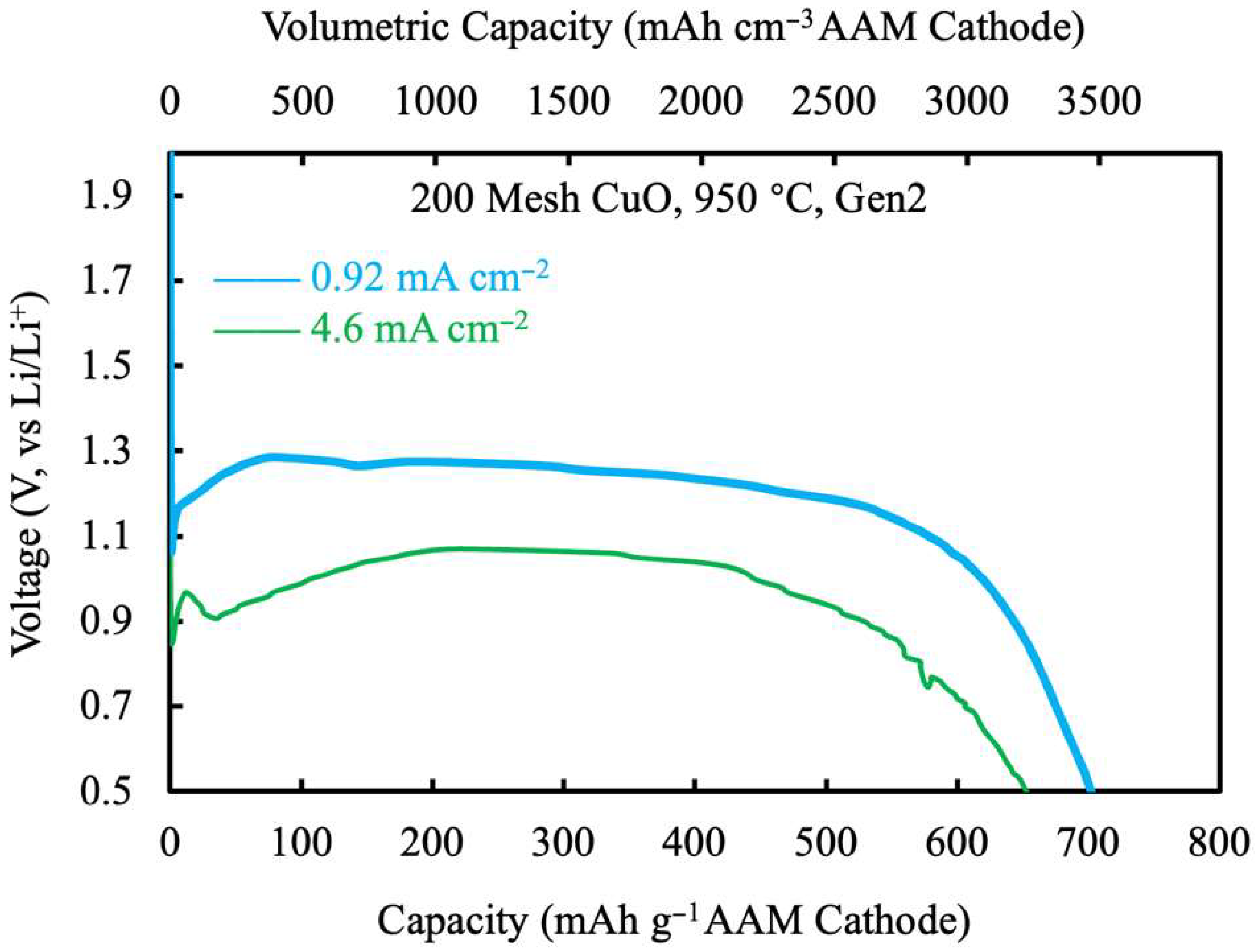
The AAM CuO positive electrode paired with Li metal negative electrode and Gen2 electrolyte discharge voltage profiles are shown in Figure 3. At a low rate of 0.92 mA cm−2 (~C/130), the capacity reached 700 mAh g−1 CuO, and a high volumetric capacity of 3460 mAh cm−3 AAM cathode (i.e., cathode electrode basis), or 1300 mAh cm−3 after balanced with Li metal (full-cell electrodes-only basis). The voltage plateau was similar to the conventional composite electrode with early capacity at close to 1.3 V, although there was a dip in voltage at the beginning of discharge. This dip and then recovery of voltage was consistent with the electronic conductivity increasing as CuO was more lithiated. This would result in relatively high initial polarization for electronic matrix resistance, which then decreased as the active material was lithiated and the matrix electronic conductivity improved [43]. At higher discharge rate of 4.6 mA cm−2, the voltage plateau (after recovery) was lowered to ~1.1 V, but still over 650 mAh g−1 was delivered. The increased overpotential possibly originated from the low electroactive surface area of the 200-mesh CuO powder (74 µm, much greater than most battery material powders) which would result in relatively high interfacial resistance. An additional assessment that was conducted for the cells was retention of capacity with storage. A cell was stored for 6 months at room temperature, and then discharged at the same lower rate current density of 0.92 mA cm−2. No noticeable differences in the voltage profiles were observed, and the resulting discharge profiles can be found in Supporting Information, Figure S5.
Figure 3.
Discharge voltage profiles for 200-mesh CuO heated at 950 °C discharged at 0.92 mA cm−2 (blue) and 4.6 mA cm−2 (green). The slower rate had a discharge time of about 130 hours.
3.2. FeS2
The XRD of the 99FeS2 can be found in Supporting Information, Figure S6. The material had a hexagonal structure consistent with literature reports for similar materials [2], and no impurity peaks were noticed. Like with the CuO material, the 99FeS2 material was initially evaluated in a conventional composite cathode paired with a Li metal anode with Gen2 electrolyte. The cell was discharged at a slow rate of 0.1 mA cm−2 (~C/50), and the resulting discharge voltage profile can be found in Supporting Information, Figure S7. The discharge had a shallow-sloped voltage region mostly between ~1.35 and 1.45 V, which started to more sharply decrease after ~ 800 mAh g−1 99FeS2. The final capacity at the 0.5 V cutoff voltage was 945 mAh g−1 FeS2, which was consistent with other literature reports for FeS2 [2,44]. The capacity also exceeded the theoretical capacity of 890 mAh g−1 99FeS2, which, as also discussed for the CuO, was suspected to be due to capacity from electrolyte decomposition in the lower voltage regions.
Unlike CuO, thermal treatment of FeS2 did not reduce either thickness or diameter of a pellet at the processing temperature of 500 °C. Heating at 550 °C was attempted, but at this temperature significant mass loss was observed, suggesting the loss of sulfur. The onset of sulfur loss near this temperature range was consistent with previous thermal analysis of FeS2 materials [45]. Lower temperatures would not facilitate densification, and thus, only one processing temperature (500 °C) was evaluated. The porosity of AAM 99FeS2 electrodes as a function of compression pressure are shown in Supporting Information, Figure S8. By increasing pressure from 25 MPa to 225 MPa, the porosity decreased from 42 vol% to 32 vol%. Decreased porosity via increased pressure has been observed for previous ceramic powder systems and can also be implemented to improve mechanical strength [46,47], which could also potentially improve the electrochemical stability for AAM electrodes [36]. XRD was conducted on the 500 °C-treated 99FeS2 AAM electrode, and the resulting pattern can be found in Supporting Information, Figure S6. There were no noticeable changes to the XRD pattern before and after the thermal treatment, and no impurity peaks were observed. An optical microscopy image of the surface of an AAM FeS2 electrode after processing can be found in Supporting Information, Figure S9. Compared to CuO, the inter-particle connections were less pronounced, which was consistent with the unchanged dimensions for the FeS2 after heat treatment (where in contrast the CuO slightly shrunk in macroscopic dimensions).
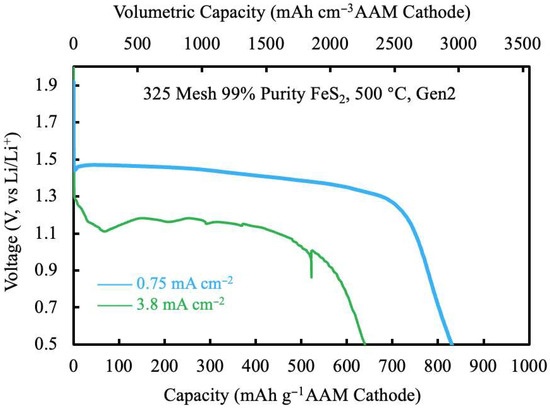
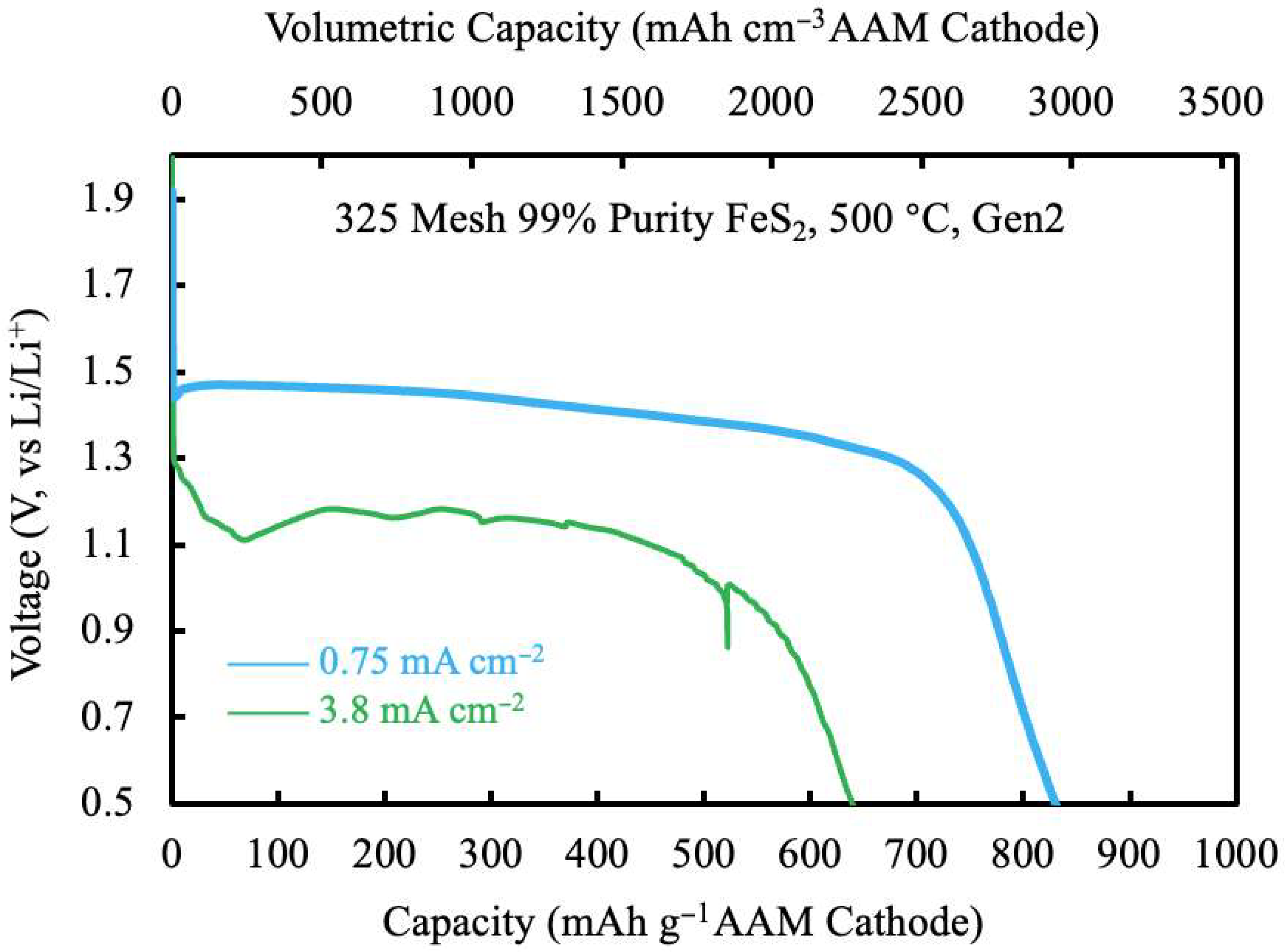
The AAM 99FeS2 cell with Li metal anode and Gen2 electrolyte discharge voltage profiles are shown in Figure 4. At low rate of 0.75 mA cm−2 (~C/120), the capacity reached 830 mAh g−1 99FeS2, which corresponded to a volumetric capacity of 2950 mAh cm−3 for the AAM cathode and 1210 mAh cm−3 on an electrode-only basis for a cell balanced with a Li metal anode. The voltage profile was similar to the conventional composite electrode with a shallow-sloped region at ~1.4 V. Unlike CuO, the initial voltage dip was much smaller, which was attributed to the higher electronic conductivity (100–101 S cm−1 [48]) before lithiation compared to that of CuO (10−2–10−3 S cm−1 [28]). At a higher discharge current density of 3.8 mA cm−2, the voltage was lowered to ~1.2 V, but still over 630 mAh g−1 was delivered. It is noted here that the absolute discharge currents evaluated for both CuO and 99FeS2 cells in Figure 3 and Figure 4 were 1 mA and 5 mA; however, the current densities were slightly different due to shrinkage of the CuO pellet after thermal treatment. A cell was stored for 6 months at room temperature, and then discharged at the same lower rate current density of 0.75 mA cm−2. The voltage profiles were very similar, and both capacities were over 800 mAh g−1. There was slightly higher initial overpotential for the stored cell relative to the fresh cell, but the voltage recovered within the first 10% of delivered capacity. The resulting discharge profiles can be found in Supporting Information, Figure S10.
Figure 4.
Discharge voltage profiles for 99FeS2 heated at 500 °C discharged at 0.75 mA cm−2 (blue) and 3.8 mA cm−2. The lower rate had a discharge time of about 120 hours.
3.3. 395/927 Benchmark Button Cells
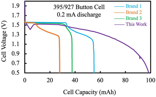
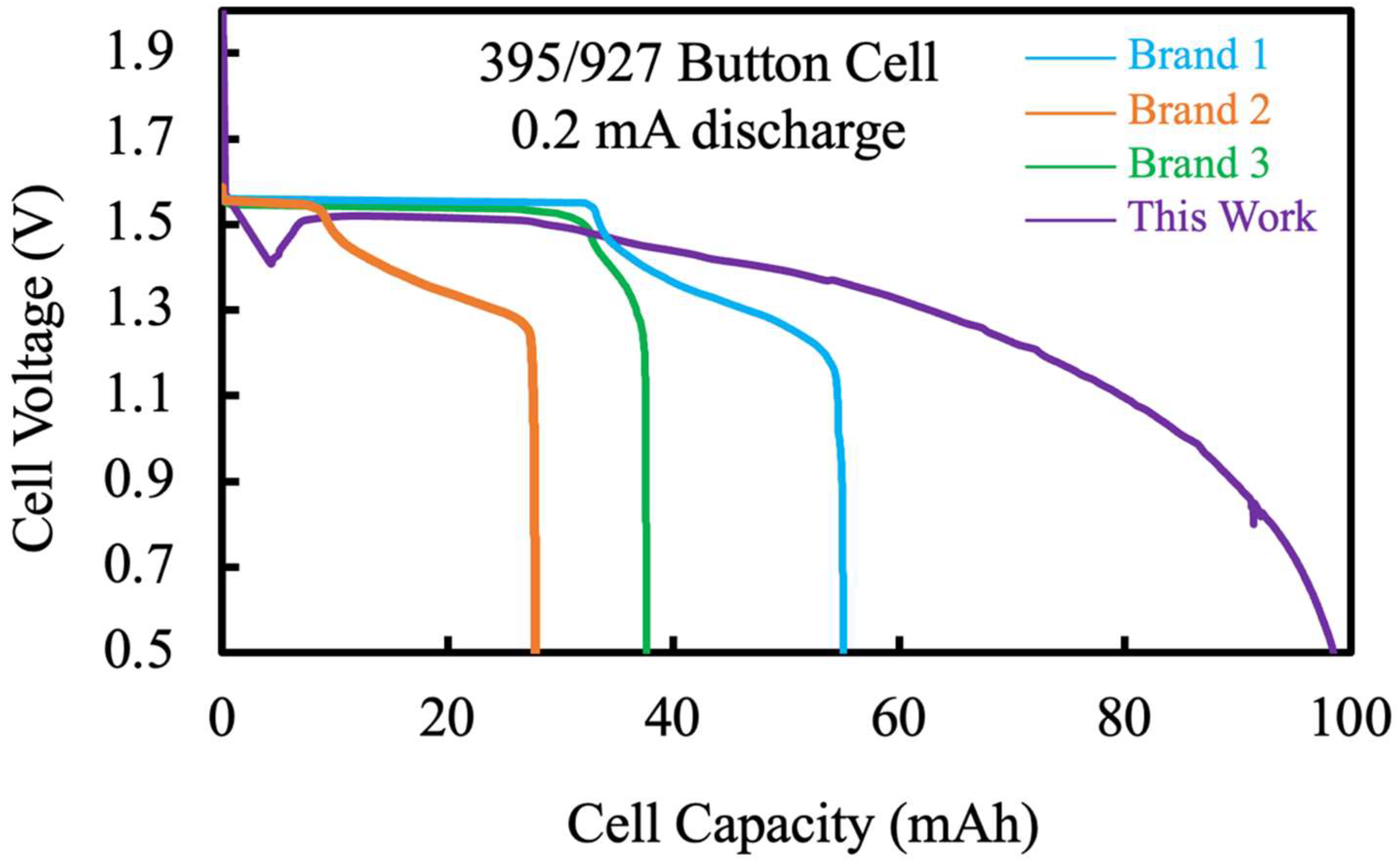
To further assess the effectiveness of implementing AAM cathodes in application-relevant small form factor cells, 395/927 button cells were fabricated with high loading of the electrodes within the cell geometry. Having wide range of uses in wearable and health applications, 395/927 cells have a diameter of 9 mm and thickness of 2.7 mm. For the benchmark, FeS2 was chosen as the cathode material, because CuO shrank after thermal treatment, and thus, it was more straightforward to match the FeS2 with the button cell case. More specifically, the 95FeS2 powder was chosen because it would be more practical to use lower-cost industrial-grade material if possible. The AAM 95FeS2 had a diameter of 7 mm, thickness of 1.1 mm, mass of 127 mg, and porosity of 40 vol.%. The Li metal mass was 27 mg. Assuming a practical capacity of 830 mAh g−1 FeS2 (from Figure 4), the capacity ratio between anode and cathode was 1:1.01. The cell was discharged at 0.2 mA (0.52 mA cm−2) and delivered almost 100 mAh, with the voltage profile shown in Figure 5. A duplicate cell was fabricated and discharged using the same conditions, and the resulting voltage profile can be found in Supporting Information, Figure S11. The capacity and voltage were similar, with both cells nearly achieving 100 mAh total capacity delivered. The current state-of-the-art 1.5 V battery is Zn-Ag2O batteries, with multiple commercial brands available. Commercial 395/927 cells were purchased from three different major brands and discharged at the same fixed 0.2 mA current, and their discharge profiles can be found in Figure 5. The delivered discharge capacity of the commercial cells ranged from 27 to 55 mAh, which was greatly surpassed by the cells in this work. This form factor of battery often has the capacity specified at a low rate and is intended for relatively low drain applications; however, the AAM and commercial cells were also compared at an increased total current of 1 mA. At this higher current, the capacity of the cell fabricated with an AAM 95FeS2 cathode had the delivered capacity drop to slightly below 60 mAh (voltage profile can be found in Supporting Information, Figure S12). This capacity still exceeded the commercial cells, which ranged from 10 to 35 mAh. It is noted that the overpotential was greater for the cell in this work fabricated with an AAM cathode compared to the commercial cells. This difference was likely due to the lower ionic conductivity of the organic electrolyte used in this work compared to the aqueous electrolyte in the commercial cells, resulting in higher ohmic resistance and ionic overpotential in the cathode that became more significant at increased current density.
Figure 5.
Discharge voltage profiles for 395/927 button cells from Brand 1 (blue), Brand 2 (orange), Brand 3 (green), and this work (purple). The discharge current was constant at 0.2 mA.
4. Conclusions
The current state-of-the-art Zn-Ag2O button cells have limited volumetric energy density due to the low volume utilization of electroactive material. This low utilization originates from the incorporation of inactive materials in the electrode microstructure, such as gelling agents, binders, and conductive additives. This work investigated alternative cell materials of Li-CuO and Li-FeS2 using AAM electrode architectures that were free of inactives to improve volume utilization. AAM electrodes were fabricated by hydraulic compression followed by heat treatment, which assisted in densification and forming inter-particle connections that aided electronic conductivity and mechanical integrity that are necessary for any battery electrode to function properly. AAM electrode processing parameters were assessed, where the CuO densification was impacted by the sintering temperature, particle size, and compression pressure. In contrast, FeS2 densification was negligible due to low sintering temperature, where more aggressive thermal treatments were not conducted due to material stability limitations. At the cathode level, high volumetric capacity over ~3000 mAh cm−3 was achieved. When including both electrodes, at the total cell electrode level, the volumetric capacity reached over 1300 mAh cm−3. In a 395/927 button cell format, nearly 100 mAh was delivered, which compares favorably with commercially available options, which typically range from 27 to 55 mAh. After 6 months of storage, the capacity retention remained above 99.9%, indicating a low self-discharge rate.
Supplementary Materials
The following supporting information can be downloaded at https://www.mdpi.com/article/10.3390/en19030615/s1, Figure S1: XRD patterns for AAM CuO electrode processed at 950 °C (green) and the as-received pristine CuO material (purple). Figure S2: Discharge voltage profile for 200-mesh CuO active material processed into a conventional composite electrode at a rate of ~C/20. The current density was 0.08 mA cm−2 and the anode was Li metal. Figure S3: The porosity of (a) 200-mesh CuO, (b) 325-mesh CuO, and (c) 800-mesh CuO compressed at 75 (blue), 150 (orange), and 225 (green) MPa as a function of heating temperature. 200 mesh, 325 mesh, and 800 mesh size corresponds to maximum particle size of 74 µm, 44 µm, and 18 µm, respectively. Fewer temperatures were investigated for 200-mesh CuO due to relatively low change at 900 °C relative to initial compression. Figure S4: Optical microscopy image of the AAM CuO electrode. Figure S5: Discharge voltage profiles for 200-mesh CuO heated at 950 °C discharged at 0.92 mA cm−2 right after cell fabrication (blue) and stored at room temperature for 6 months (orange). The total discharge time for each cell was about 130 hours. Figure S6: XRD patterns for AAM FeS2 electrode processed at 500 °C (green) and the as-received pristine FeS2 material (purple). Figure S7: Discharge voltage profile at ~C/50 for 99% purity FeS2 active material processed into a conventional composite electrode. The current density was 0.1 mA cm−2 and anode was Li metal. Figure S8: The porosity of 325-mesh 99% purity FeS2 as a function of compression pressure. Porosity was the same both before and after heat treatment at 500 °C. Figure S9: Optical microscopy image of the AAM FeS2 electrode. Figure S10: Discharge voltage profiles for 99FeS2 heated at 500 °C discharged at 0.75 mA cm−2 right after cell fabrication (blue) and stored in room temperature for 6 months (orange). The discharge time was about 120 hours. Figure S11: Discharge voltage profile for the duplicate 395/927 button cell made nominally the same as the one that resulted in the data in Figure 5 in the main text. The discharge current was constant at 0.2 mA. Figure S12: Discharge voltage profiles for 395/927 button cells from Brand 1 (blue), Brand 2 (orange), Brand 3 (green), and this work (purple). The discharge current was constant at 1.0 mA. Table S1: Electroactive material powder used in this work.
Author Contributions
Conceptualization, C.C. and G.M.K.J.; methodology, C.C. and B.M.; validation, C.C. and G.M.K.J.; formal analysis, C.C. and G.M.K.J.; investigation, C.C. and B.M.; resources, C.C. and G.M.K.J.; data curation, C.C.; writing—original draft preparation, C.C.; writing—review and editing, C.C. and G.M.K.J.; visualization, C.C.; supervision, G.M.K.J.; project administration, G.M.K.J.; funding acquisition, G.M.K.J. All authors have read and agreed to the published version of the manuscript.
Funding
This work was in part supported by funds from the Virginia Innovation Partnership Corporation (CCF24-0019-HE), and University of Virginia Licensing and Ventures Group.
Data Availability Statement
The original contributions presented in the study are included in the article; further inquiries can be directed to the corresponding author.
Acknowledgments
The authors would like to thank Nippon Shokubai for providing electrolyte salts.
Conflicts of Interest
The authors declare no conflicts of interest.
Abbreviations
The following abbreviations are used in this manuscript:
| PVB | Polyvinyl butyral |
| PVP | Polyvinyl pyrrolidone |
| CB | Acetylene carbon black |
| EC | Ethylene carbonate |
| EMC | Ethyl methyl carbonate |
| XRD | X-ray diffraction |
References
- Wang, K.; Di, A.; Zhang, S.; Ni, L.; Wang, H.; Liu, H.; Huang, Y.; Mao, Y.; Xie, J.; Zou, G.; et al. Zinc Anode Based Alkaline Energy Storage System: Recent Progress and Future Perspectives of Zinc–Silver Battery. Energy Storage Mater. 2024, 69, 103385. [Google Scholar] [CrossRef] [Scilit]
- Shao-Horn, Y.; Osmialowski, S.; Horn, Q.C. Nano- FeS2 for Commercial Li / FeS2 Primary Batteries. J. Electrochem. Soc. 2002, 149, A1499. [Google Scholar] [CrossRef] [Scilit]
- Hibble, S.J.; Malitesta, C.; Dickens, P.G. The Chemical and Electrochemical Lithiation of CuO: An Analytical, Electron Microscopy Investigation. Solid State Ion. 1990, 39, 289–295. [Google Scholar] [CrossRef] [Scilit]
- Krishnamoorthy, A.; Herbert, F.W.; Yip, S.; Van Vliet, K.J.; Yildiz, B. Electronic States of Intrinsic Surface and Bulk Vacancies in FeS2. J. Phys. Condens. Matter 2013, 25, 45004. [Google Scholar] [CrossRef] [Scilit]
- Bezza, F.A.; Tichapondwa, S.M.; Chirwa, E.M.N. Fabrication of Monodispersed Copper Oxide Nanoparticles with Potential Application as Antimicrobial Agents. Sci. Rep. 2020, 10, 16680. [Google Scholar] [CrossRef] [Scilit]
- Hu, W.; Yao, Y.; Huang, X.; Ju, S.; Chen, Z.; Li, M.; Wu, Y. CuO Nanofilm-Covered Cu Microcone Coating for a Long Cycle Li Metal Anode by In Situ Formed Li2O. ACS Appl. Energy Mater. 2022, 5, 3773–3782. [Google Scholar] [CrossRef] [Scilit]
- Takeuchi, T.; Kageyama, H.; Nakanishi, K.; Inada, Y.; Katayama, M.; Ohta, T.; Senoh, H.; Sakaebe, H.; Sakai, T.; Tatsumi, K.; et al. Improvement of Cycle Capability of FeS2 Positive Electrode by Forming Composites with Li2S for Ambient Temperature Lithium Batteries. J. Electrochem. Soc. 2011, 159, A75. [Google Scholar] [CrossRef] [Scilit]
- Huang, B.; Tai, K.; Dillon, S.J. Structural Evolution of α-Fe2O3 Nanowires during Lithiation and Delithiation. J. Power Sources 2014, 245, 308–314. [Google Scholar] [CrossRef] [Scilit]
- Huie, M.M.; Bock, D.C.; Bruck, A.M.; Tallman, K.R.; Housel, L.M.; Wang, L.; Thieme, J.; Takeuchi, K.J.; Takeuchi, E.S.; Marschilok, A.C. Isothermal Microcalorimetry: Insight into the Impact of Crystallite Size and Agglomeration on the Lithiation of Magnetite, Fe3O4. ACS Appl. Mater. Interfaces 2019, 11, 7074–7086. [Google Scholar] [CrossRef] [Scilit] [PubMed]
- Abbas, S.M.; Ahmad, N.; Ata-ur-Rehman; Rana, U.A.; Khan, S.U.-D.; Hussain, S.; Nam, K.-W. High Rate Capability and Long Cycle Stability of Cr2O3 Anode with CNTs for Lithium Ion Batteries. Electrochim. Acta 2016, 212, 260–269. [Google Scholar] [CrossRef] [Scilit]
- Gao, J.; Lowe, M.A.; Abruña, H.D. Spongelike Nanosized Mn3O4 as a High-Capacity Anode Material for Rechargeable Lithium Batteries. Chem. Mater. 2011, 23, 3223–3227. [Google Scholar] [CrossRef] [Scilit]
- Huang, G.; Xu, S.; Lu, S.; Li, L.; Sun, H. Micro-/Nanostructured Co3O4 Anode with Enhanced Rate Capability for Lithium-Ion Batteries. ACS Appl. Mater. Interfaces 2014, 6, 7236–7243. [Google Scholar] [CrossRef] [Scilit] [PubMed]
- Phan Nguyen, T.; Thi Giang, T.; Tae Kim, I. Restructuring NiO to LiNiO2: Ultrastable and Reversible Anodes for Lithium-Ion Batteries. Chem. Eng. J. 2022, 437, 135292. [Google Scholar] [CrossRef] [Scilit]
- Kreissl, J.J.A.; Petit, J.; Oppermann, R.; Cop, P.; Gerber, T.; Joos, M.; Abert, M.; Tübke, J.; Miyazaki, K.; Abe, T.; et al. Electrochemical Lithiation/Delithiation of ZnO in 3D-Structured Electrodes: Elucidating the Mechanism and the Solid Electrolyte Interphase Formation. ACS Appl. Mater. Interfaces 2021, 13, 35625–35638. [Google Scholar] [CrossRef] [Scilit]
- Yan, B.; Li, X.; Fu, X.; Zhang, L.; Bai, Z.; Yang, X. An Elaborate Insight of Lithiation Behavior of V2O5 Anode. Nano Energy 2020, 78, 105233. [Google Scholar] [CrossRef] [Scilit]
- Dambournet, D.; Belharouak, I.; Amine, K. Tailored Preparation Methods of TiO2 Anatase, Rutile, Brookite: Mechanism of Formation and Electrochemical Properties. Chem. Mater. 2010, 22, 1173–1179. [Google Scholar] [CrossRef] [Scilit]
- Chang, Y.; Zhang, H.; Xiang, W.; Wang, S.; Zhu, X.; Yu, J. Thermodynamics, Kinetics and Crystal Structure of γ/β-MnO2 in Li/MnO2 Primary Batteries. Electrochim. Acta 2020, 339, 135918. [Google Scholar] [CrossRef] [Scilit]
- Suslov, E.A.; Bushkova, O.V.; Sherstobitova, E.A.; Reznitskikh, O.G.; Titov, A.N. Lithium Intercalation into TiS2 Cathode Material: Phase Equilibria in a Li–TiS2 System. Ionics 2016, 22, 503–514. [Google Scholar] [CrossRef] [Scilit]
- Zhang, X.; He, Q.; Xu, X.; Xiong, T.; Xiao, Z.; Meng, J.; Wang, X.; Wu, L.; Chen, J.; Mai, L. Insights into the Storage Mechanism of Layered VS2 Cathode in Alkali Metal-Ion Batteries. Adv. Energy Mater. 2020, 10, 1904118. [Google Scholar] [CrossRef] [Scilit]
- Zhou, Y.; Liu, B.; Shao, Y.; Fan, C.; Fan, R.; Wen, B. Low Temperature Oxidation Synthesis of Carbon Encapsulated Cr2O3 Nanocrystals and Its Lithium Storage Performance. Funct. Mater. Lett. 2017, 11, 1850008. [Google Scholar] [CrossRef] [Scilit]
- Ma, Y.; Ma, Y.; Kim, G.-T.; Diemant, T.; Behm, R.J.; Geiger, D.; Kaiser, U.; Varzi, A.; Passerini, S. Superior Lithium Storage Capacity of α-MnS Nanoparticles Embedded in S-Doped Carbonaceous Mesoporous Frameworks. Adv. Energy Mater. 2019, 9, 1902077. [Google Scholar] [CrossRef] [Scilit]
- Butala, M.M.; Doan-Nguyen, V.V.T.; Lehner, A.J.; Göbel, C.; Lumley, M.A.; Arnon, S.; Wiaderek, K.M.; Borkiewicz, O.J.; Chapman, K.W.; Chupas, P.J.; et al. Operando Studies Reveal Structural Evolution with Electrochemical Cycling in Li–CoS2. J. Phys. Chem. C 2018, 122, 24559–24569. [Google Scholar] [CrossRef] [Scilit]
- Zhang, Y.; Lu, F.; Pan, L.; Xu, Y.; Yang, Y.; Bando, Y.; Golberg, D.; Yao, J.; Wang, X. Improved Cycling Stability of NiS2 Cathodes through Designing a “Kiwano” Hollow Structure. J. Mater. Chem. A 2018, 6, 11978–11984. [Google Scholar] [CrossRef] [Scilit]
- Nam, J.S.; Lee, J.-H.; Hwang, S.M.; Kim, Y.-J. New Insights into the Phase Evolution in CuS during Lithiation and Delithiation Processes. J. Mater. Chem. A 2019, 7, 11699–11708. [Google Scholar] [CrossRef] [Scilit]
- Park, A.-R.; Jeon, K.-J.; Park, C.-M. Electrochemical Mechanism of Li Insertion/Extraction in ZnS and ZnS/C Anodes for Li-Ion Batteries. Electrochim. Acta 2018, 265, 107–114. [Google Scholar] [CrossRef] [Scilit]
- Aktas, S. Silver Recovery from Spent Silver Oxide Button Cells. Hydrometallurgy 2010, 104, 106–111. [Google Scholar] [CrossRef] [Scilit]
- Dong, X.; Chen, L.; Su, X.; Wang, Y.; Xia, Y. Flexible Aqueous Lithium-Ion Battery with High Safety and Large Volumetric Energy Density. Angew. Chem. Int. Ed. 2016, 55, 7474–7477. [Google Scholar] [CrossRef] [Scilit]
- Jeong, Y.K.; Choi, G.M. Nonstoichiometry and Electrical Conduction of CuO. J. Phys. Chem. Solids 1996, 57, 81–84. [Google Scholar] [CrossRef] [Scilit]
- Masset, P.J.; Guidotti, R.A. Thermal Activated (“Thermal”) Battery Technology: Part IIIa: FeS2 Cathode Material. J. Power Sources 2008, 177, 595–609. [Google Scholar] [CrossRef] [Scilit]
- Figueiredo, V.; Elangovan, E.; Gonçalves, G.; Barquinha, P.; Pereira, L.; Franco, N.; Alves, E.; Martins, R.; Fortunato, E. Effect of Post-Annealing on the Properties of Copper Oxide Thin Films Obtained from the Oxidation of Evaporated Metallic Copper. Appl. Surf. Sci. 2008, 254, 3949–3954. [Google Scholar] [CrossRef] [Scilit]
- Chiang, C.-Y.; Shin, Y.; Ehrman, S. Li Doped CuO Film Electrodes for Photoelectrochemical Cells. J. Electrochem. Soc. 2011, 159, B227. [Google Scholar] [CrossRef] [Scilit]
- Cai, C.; Koenig, G.M. Investigating Dopants to Improve Sintered LiMn2O4 Spinel Electrode Electrochemical Cycling Limitations. Electrochim. Acta 2021, 401, 139484. [Google Scholar] [CrossRef] [Scilit]
- Cai, C.; Yost, D.; Koenig, G.M. Increased Cycling Rates for Thick All Active Material Electrodes via Electrolyte Modifications. J. Energy Storage 2023, 64, 107238. [Google Scholar] [CrossRef] [Scilit]
- Cai, C.; Min, B.; Yost, D.; Koenig, G.M.J. Combining Ester Solvent-Containing Electrolytes with All-Active Material Electrodes for High Current Density Lithium-Ion Batteries. ACS Appl. Energy Mater. 2023, 6, 11226–11233. [Google Scholar] [CrossRef] [Scilit]
- Cai, C.; Hensley, D.; Koenig, G.M. High Capacity Rechargeable Coin Cells Using All Active Material Electrodes and Percolated Networks of LiCoO2 Blended with LiNi0.8Co0.15Al0.05O2. J. Alloys Compd. 2023, 968, 171965. [Google Scholar] [CrossRef] [Scilit]
- Cai, C.; Gao, L.; Sun, T.; Koenig, G.M.J. Stable Multicomponent Multiphase All Active Material Lithium-Ion Battery Anodes. ACS Appl. Mater. Interfaces 2023, 15, 34662–34674. [Google Scholar] [CrossRef] [Scilit]
- Cai, C.; Koenig, G.M. Enhancing Low Electronic Conductivity Materials in All Active Material Electrodes through Multicomponent Architecture. Energy Adv. 2023, 2, 308–320. [Google Scholar] [CrossRef] [Scilit]
- Zhang, Q.; Zhang, K.; Xu, D.; Yang, G.; Huang, H.; Nie, F.; Liu, C.; Yang, S. CuO Nanostructures: Synthesis, Characterization, Growth Mechanisms, Fundamental Properties, and Applications. Prog. Mater. Sci. 2014, 60, 208–337. [Google Scholar] [CrossRef] [Scilit]
- Subalakshmi, P.; Sivashanmugam, A. CuO Nano Hexagons, an Efficient Energy Storage Material for Li- Ion Battery Application. J. Alloys Compd. 2017, 690, 523–531. [Google Scholar] [CrossRef] [Scilit]
- Waser, O.; Hess, M.; Güntner, A.; Novák, P.; Pratsinis, S.E. Size Controlled CuO Nanoparticles for Li-Ion Batteries. J. Power Sources 2013, 241, 415–422. [Google Scholar] [CrossRef] [Scilit]
- Novák, P. CuO Cathode in Lithium Cells—III. Its Discharge Kinetics. Electrochim. Acta 1986, 31, 1167–1173. [Google Scholar] [CrossRef] [Scilit]
- Zhang, S.S.; Jow, T.R.; Amine, K.; Henriksen, G.L. LiPF6–EC–EMC Electrolyte for Li-Ion Battery. J. Power Sources 2002, 107, 18–23. [Google Scholar] [CrossRef] [Scilit]
- Cai, C.; Nie, Z.; Robinson, J.P.; Hussey, D.S.; LaManna, J.M.; Jacobson, D.L.; Koenig, G.M. Thick Sintered Electrode Lithium-Ion Battery Discharge Simulations: Incorporating Lithiation-Dependent Electronic Conductivity and Lithiation Gradient Due to Charge Cycle. J. Electrochem. Soc. 2020, 167, 140542. [Google Scholar] [CrossRef] [Scilit]
- Chen, J.; Zhao, Z.; Niu, R.; Yao, Y.; Liang, M.; Huang, Q.; Wang, X. Highly Stabilized FeS2 Cathode Design and Energy Storage Mechanism Study for Advanced Aqueous FeS2–Cu Battery. J. Power Sources 2024, 621, 235240. [Google Scholar] [CrossRef] [Scilit]
- Pemsler, J.P.; Lam, R.K.F.; Litchfield, J.K.; Dallek, S.; Larrick, B.F.; Beard, B.C. Discharge Behavior and Thermal Stability of Synthetic FeS2 Cathode Material. J. Electrochem. Soc. 1990, 137, 1. [Google Scholar] [CrossRef] [Scilit]
- Castillo, S.M.; Muñoz, S.; Trueba, P.; Díaz, E.; Torres, Y. Influence of the Compaction Pressure and Sintering Temperature on the Mechanical Properties of Porous Titanium for Biomedical Applications. Metals 2019, 9, 1249. [Google Scholar] [CrossRef] [Scilit]
- Güden, M.; Çelik, E.; Hızal, A.; Altındiş, M.; Çetiner, S. Effects of Compaction Pressure and Particle Shape on the Porosity and Compression Mechanical Properties of Sintered Ti6Al4V Powder Compacts for Hard Tissue Implantation. J. Biomed. Mater. Res. Part B Appl. Biomater. 2008, 85B, 547–555. [Google Scholar] [CrossRef] [Scilit] [PubMed]
- Schieck, R.; Hartmann, A.; Fiechter, S.; Könenkamp, R.; Wetzel, H. Electrical Properties of Natural and Synthetic Pyrite (FeS2) Crystals. J. Mater. Res. 1990, 5, 1567–1572. [Google Scholar] [CrossRef] [Scilit]
Disclaimer/Publisher’s Note: The statements, opinions and data contained in all publications are solely those of the individual author(s) and contributor(s) and not of MDPI and/or the editor(s). MDPI and/or the editor(s) disclaim responsibility for any injury to people or property resulting from any ideas, methods, instructions or products referred to in the content. |
© 2026 by the authors. Licensee MDPI, Basel, Switzerland. This article is an open access article distributed under the terms and conditions of the Creative Commons Attribution (CC BY) license.