


Abstract
The Z-source inverter (ZSI) has emerged as an effective single-stage power conversion topology for renewable energy applications owing to its inherent capability to perform both voltage buck and boost operations. However, the shoot-through states required for voltage boosting introduce additional harmonic distortion that can degrade output power quality and increase the dependence on passive filtering. This paper presents a comparative performance analysis of conventional and strategic PWM shoot-through placement within the maximum boost control (MBC) framework for three-phase Z-source inverters. A strategic shoot-through placement approach, referred to as modified maximum boost control (MMBC), is proposed to redistribute shoot-through intervals while using the conventional theoretical shoot-through duty ratio as the operating reference. Both control strategies were modelled and evaluated in MATLAB/Simulink R2024a version under identical operating conditions. Their performance was assessed using voltage total harmonic distortion (THDV), fundamental output voltage magnitude, and the corresponding voltage gain and boost factor relationships. The simulation results indicate that the proposed MMBC achieved a minimum THDV of approximately 1.73%, compared with 4.05% obtained using conventional MBC. The improved harmonic performance was accompanied by a reduction in the output voltage magnitude, highlighting the trade-off between power quality enhancement and voltage utilisation. These findings demonstrate that strategic PWM shoot-through placement can substantially improve the output voltage power quality of Z-source inverters, indicating its potential applicability to renewable energy conversion systems where reduced output voltage harmonic distortion is prioritised.
1. Introduction
The increasing deployment of renewable energy systems has intensified the demand for efficient and reliable power electronic converters capable of delivering high-quality electrical power [1]. Renewable energy technologies, particularly photovoltaic (PV) and wind energy systems, require power conversion interfaces that not only provide efficient energy transfer but also maintain acceptable power quality under varying operating conditions [1,2]. Consequently, inverter topologies that combine high voltage conversion capability with reduced circuit complexity have become an important area of research [2].
Among the available converter topologies, the Z-source inverter (ZSI) has emerged as an attractive alternative to conventional Voltage Source Inverters (VSIs) and Current Source Inverters (CSIs) [3]. Unlike traditional inverter topologies, the ZSI employs a unique impedance network that permits intentional shoot-through switching states without damaging the semiconductor devices. This characteristic enables the converter to perform voltage buck and boost operations within a single power conversion stage, eliminating the need for an additional DC-DC boost converter while improving system flexibility and reliability [3].
The voltage boosting capability of the ZSI is achieved by introducing shoot-through intervals into the pulse width modulation (PWM) switching sequence [4]. During these intervals, both switches within the same inverter leg are intentionally turned on simultaneously, allowing energy to be transferred through the impedance network and increasing the inverter output voltage [4]. Although this operating principle offers significant advantages, the inclusion of shoot-through states also influences the harmonic characteristics of the output waveform. Excessive harmonic distortion degrades power quality, increases filtering requirements, and may reduce compliance with grid interconnection standards, particularly in renewable energy applications where stringent harmonic limits must be satisfied [5].
Several PWM techniques have been proposed to enhance the operational performance of Z-source inverters, with maximum boost control (MBC) being widely adopted because of its effective utilisation of the available shoot-through interval [4,6,7]. Existing research has primarily focused on improving boost performance, modulation range, and voltage conversion efficiency. Comparatively less attention has been devoted to investigating how the temporal distribution of shoot-through states within the PWM switching cycle influences harmonic performance. Consequently, the potential benefits of strategically positioning shoot-through intervals to improve output power quality while retaining the fundamental MBC operating structure remain insufficiently explored.
This paper addresses this research gap by introducing a strategic PWM shoot-through placement approach within the conventional MBC framework. The proposed implementation, referred to as MMBC, strategically redistributes shoot-through intervals throughout the PWM switching sequence while maintaining the fundamental operating principles of conventional MBC. The performance of the conventional MBC and the proposed MMBC strategies are evaluated under identical operating conditions using MATLAB/Simulink.
The comparative analysis evaluates the simulated fundamental phase-voltage magnitude and voltage total harmonic distortion (THDV), with the theoretical boost factor and voltage gain used as analytical reference quantities. The results demonstrate that the proposed MMBC significantly improves output voltage quality while modifying the effective voltage utilisation of the inverter. By improving output voltage harmonic performance without introducing additional hardware, the proposed strategy provides an alternative PWM approach for power conversion systems where reduced voltage harmonic distortion is a design priority.
The principal contributions of this paper are summarised as follows:
- A strategic PWM shoot-through placement method is developed within the maximum boost control framework.
- A modified maximum boost control (MMBC) strategy is introduced as a strategic implementation of conventional MBC.
- A comparative performance evaluation between conventional MBC and the proposed MMBC is conducted under identical operating conditions.
- The influence of strategic shoot-through placement on voltage gain, boost factor, and voltage total harmonic distortion (THDV) is quantitatively assessed.
- The proposed MMBC demonstrates a substantial reduction in harmonic distortion while altering the effective output voltage utilisation of the inverter.
2. Literature Review
Pulse width modulation (PWM) techniques play a significant role in determining the performance of Z-source inverters (ZSIs) by controlling the generation of shoot-through states required for voltage boosting [4]. Unlike conventional Voltage Source Inverters (VSIs), which prohibit simultaneous conduction of the upper and lower switches within the same inverter leg, the ZSI employs an impedance network that safely permits shoot-through operation [3]. During the shoot-through interval, energy is stored in the impedance network and subsequently transferred to increase the dc-link voltage, enabling the inverter to perform both voltage buck and boost operations within a single conversion stage [3]. This unique operating principle has made the ZSI an attractive topology for photovoltaic systems, wind energy conversion, and other renewable energy applications [6,7].
Although the shoot-through operating mode provides the voltage boosting capability that distinguishes the ZSI from conventional inverter topologies, it also influences the harmonic characteristics of the output voltage waveform [3]. The insertion of shoot-through intervals modifies the inverter switching sequence, which may increase voltage total harmonic distortion (THDV) and consequently degrade output power quality [8]. Increased harmonic distortion often necessitates larger passive filters to satisfy grid interconnection standards, thereby increasing system cost and complexity [5,8]. Consequently, considerable research has focused on developing PWM strategies that achieve an appropriate balance between voltage boosting capability and harmonic performance [4,7].
Several PWM strategies have been reported in the literature for controlling Z-source inverters, including Constant Boost Control (CBC), Simple Boost Control (SBC), and maximum boost control (MBC). These techniques differ primarily in how shoot-through intervals are generated and distributed throughout the switching period. SBC is recognised for its simple implementation but provides limited voltage boosting capability. CBC improves voltage utilisation through third-harmonic injection while maintaining a constant shoot-through duty ratio [7]. Among these conventional approaches, maximum boost control has received considerable attention because it fully utilises the available zero switching states to maximise the boost factor without requiring additional hardware [4,7].
Maximum boost control is widely used because of its relatively simple control structure and effective utilisation of available zero switching states [4]. By allocating shoot-through intervals to every available zero state, MBC maximises the voltage boosting capability of the Z-source inverter and has therefore become one of the most widely adopted PWM strategies in both research and practical applications. However, conventional MBC primarily allocates the available zero states to maximise voltage gain rather than explicitly optimising harmonic performance [4,7]. The numerical implementation and comparative evaluation were conducted using MATLAB/Simulink [9]. Carrier-based implementations of impedance source inverters have also been investigated to improve the generation and control of shoot-through states while maintaining the required inverter switching operation [10].
The modulation and control characteristics of three-phase impedance source inverters have been comprehensively classified in the literature, with different modulation schemes distinguished according to how shoot-through states are generated and distributed among the inverter legs [11]. Such classification provides a basis for comparing the operating principles of different modulation strategies and for analysing their effects on the voltage boosting capability and switching behaviour of impedance source inverters [11]. Comparative investigations have further shown that the selection of a modulation strategy affects several inverter performance characteristics, including voltage gain, semiconductor voltage and current stresses, effective switching frequency, output voltage spectrum, and switching losses [12]. These comparisons demonstrate that the modulation strategy influences not only the voltage boosting capability of the impedance source inverter but also the characteristics of its output waveform. Previous studies have also investigated alternative shoot-through distribution approaches in impedance source inverter systems. For example, a novel modulation technique incorporating specific shoot-through-state distribution has been investigated for a three-level three-phase quasi-Z-source neutral-point-clamped inverter, demonstrating the importance of shoot-through-state generation and distribution within the modulation process [13].
Recent investigations have shown that different shoot-through-state insertion and distribution patterns can produce different harmonic characteristics and harmonic behaviour of impedance source inverters [8,13,14]. This observation suggests that the temporal placement of shoot-through intervals provides an additional degree of freedom for improving output waveform quality.
Previous investigations have evaluated Z-source inverter performance using parameters such as boost factor, modulation index, voltage gain, switching stress, and total harmonic distortion (THD). Recent research has also demonstrated that the distribution of shoot-through states within the PWM switching sequence can influence the harmonic characteristics of Z-source inverter outputs [6]. However, comparatively limited attention has been given to the strategic redistribution of shoot-through intervals within the conventional maximum boost control framework while retaining its established control structure.
Motivated by this research gap, this study investigates strategic PWM shoot-through placement within the maximum boost control framework. Rather than introducing a new converter topology or additional switching hardware, the proposed approach redistributes the existing shoot-through intervals within the PWM switching sequence. This strategic implementation is referred to as modified maximum boost control (MMBC). A comparative performance analysis between conventional MBC and the proposed MMBC is conducted using MATLAB/Simulink under identical operating conditions [9]. The evaluation focuses on the simulated fundamental phase-voltage magnitude and voltage total harmonic distortion (THDV), with voltage gain and boost factor treated as theoretical reference quantities for assessing the influence of shoot-through placement on output voltage quality and voltage utilisation.
3. Methodology
This study evaluates the influence of strategic pulse width modulation shoot-through placement on the performance of a three-phase impedance source inverter operating under the MBC strategy. Rather than introducing a new converter topology or modifying the underlying MBC control structure, the proposed approach strategically redistributes the shoot-through intervals within the PWM switching sequence [4]. This strategic implementation is referred to as modified maximum boost control (MMBC).
To ensure a fair comparison, both the conventional MBC and the proposed MMBC were implemented using an identical three-phase Z-source inverter model developed in MATLAB/Simulink [9]. The two control strategies were evaluated using the same inverter topology, electrical parameters, input voltage, switching frequency, load conditions, and modulation index range. This common simulation framework allows the differences in simulated output voltage performance and THDV to be assessed under equivalent operating conditions, with the principal control modification being the temporal placement of the shoot-through intervals.
3.1. Development of the Reference Z-Source Inverter Model
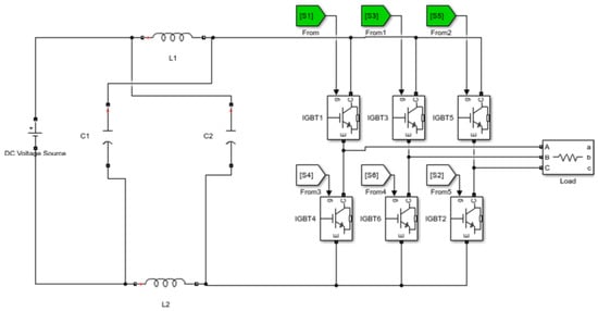
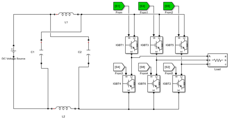
A reference three-phase Z-source inverter model was developed in MATLAB/Simulink to provide a common platform for evaluating both control strategies [9]. The simulation model consists of a DC voltage source, a symmetrical impedance network comprising inductors and capacitors, a three-phase inverter bridge, and a balanced three-phase load, as illustrated in Figure 1.
Figure 1.
Reference three-phase Z-source inverter model implemented in MATLAB/Simulink.
The impedance network permits safe shoot-through operation by limiting the short-circuit current while simultaneously storing and releasing energy to achieve voltage boosting. During shoot-through operation, energy is accumulated in the impedance network and subsequently transferred to increase the dc-link voltage supplied to the inverter bridge [3]. This operating principle forms the basis for implementing both the conventional MBC and proposed MMBC strategies.
The performance of the conventional MBC and the proposed MMBC strategies were evaluated under identical simulation conditions using MATLAB/Simulink. To ensure a fair comparison, the same inverter parameters, impedance-network components, DC input voltage, switching frequency, and load conditions were used for both controllers at each operating point. The modulation index was varied over the specified range for the parametric analysis. The simulation parameters adopted in this study are summarised in Table 1.
Table 1.
Simulation parameters.
The ZSI parameter values listed in Table 1 were obtained using the following design equations [4].
where VC is the capacitor voltage, DST is the duty ratio, ∆I is the change in ripple current, and fsw is the switching frequency.
where Iavg is the average current and ∆V is the change in ripple voltage.
where VDC is the dc input voltage.
where F is the frequency and XC is the capacitive reactance.
Voltage total harmonic distortion (THDV) was determined using the MATLAB Powergui Fast Fourier Transform (FFT) analysis tool after the inverter reached steady-state operation. The fundamental phase-voltage magnitude was obtained from the same FFT analysis of the simulated phase-to-ground output voltage. The theoretical boost factor and corresponding DC-link voltage were calculated from the established MBC relationships in (5)–(8) and were used as analytical reference quantities. The simulated fundamental phase-voltage magnitude and THDV were then used to compare the conventional MBC and proposed MMBC under identical operating conditions. The simulated performance of the proposed MMBC strategy was subsequently compared with that of the conventional MBC under identical operating conditions to quantify the influence of strategic shoot-through redistribution on the harmonic performance and voltage boosting characteristics of the Z-source inverter.
3.2. Conventional Maximum Boost Control
The conventional maximum boost control (MBC) strategy was implemented as the reference controller for evaluating the proposed modified maximum boost control (MMBC). Unlike the Simple Boost Control (SBC) and Constant Boost Control (CBC) techniques, MBC utilises the available zero switching states to generate shoot-through intervals within each switching cycle [4]. This enables MBC to achieve a high boost factor while retaining a relatively simple control structure.
Following the impedance-network design, the conventional MBC strategy was implemented to generate the shoot-through intervals required by the modulation scheme.
For a given modulation index, the theoretical shoot-through duty ratio of conventional MBC is obtained from the established MBC relationship [4]
where M is the modulation index and D0 is the shoot-through duty ratio.
Substituting (5) into the general Z-source inverter boost relationship yields the theoretical boost factor of the conventional MBC strategy:
where B is the boost factor
The voltage gain of the inverter is determined by the product of the modulation index and the boost factor and is expressed as
The resulting theoretical dc-link voltage is therefore given by
where Vin is the input dc voltage.
VDC = BVin dc − link
The theoretical boost factor and DC-link voltage are determined from (5)–(8) and are used as analytical reference quantities for establishing the MBC operating point. These quantities are not obtained from the simulated output waveform. In contrast, the fundamental phase-voltage magnitude and voltage THD are obtained directly from FFT analysis of the simulated phase-to-ground output voltage. Therefore, the performance comparison between conventional MBC and the proposed MMBC is based primarily on the simulated fundamental phase-voltage magnitude and THD, while the boost factor and DC-link voltage provide the corresponding theoretical operating reference. This distinction is maintained throughout the results to clearly separate the analytical MBC quantities from the simulated output voltage performance.
For M = 0.6, the denominator of (6), , is negative, resulting in a negative theoretical boost factor. This operating point is therefore outside the physically meaningful operating region of the analytical MBC boost relationship, whose limiting modulation index is . Consequently, the theoretical boost factor and corresponding dc-link voltage are reported as undefined at M = 0.6. The M = 0.6 case was nevertheless retained in the simulation study to evaluate the implemented switching controller. The corresponding fundamental phase-voltage magnitude is obtained directly from the simulated phase-to-ground waveform using FFT analysis and does not require calculation of the theoretical boost factor. Therefore, the M = 0.6 simulated fundamental phase-voltage result is treated solely as a simulation result and is not used to determine the theoretical boost factor or dc-link voltage.
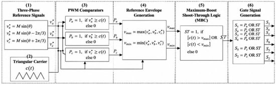
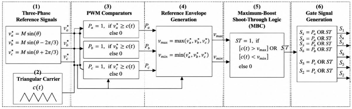
The MATLAB/Simulink implementation of the conventional MBC controller is illustrated in Figure 2. The control sequence consists of three principal stages: carrier-based reference comparison, MBC shoot-through generation, and inverter gate signal generation. The mathematical definitions below make the switching logic explicit and reproducible.
Figure 2.
Conventional maximum boost control (MBC) control logic.
3.2.1. Reference Comparison Stage
The three-phase sinusoidal reference signals are defined as
where M is the modulation index and θ = 2πf1t, with f1 representing the fundamental frequency. Each reference signal is compared with the common triangular carrier vcar(t) to generate the corresponding PWM switching function:
This comparison establishes the conventional carrier-based PWM switching sequence for the three inverter legs.
3.2.2. Shoot-Through Generation Stage
The conventional MBC controller generates the shoot-through signal by first determining the instantaneous maximum and minimum values of the three-phase reference signals. These reference envelopes are continuously compared with the carrier waveform using the upper (Vmax) and lower (Vmin) threshold conditions. Whenever the predefined MBC switching criteria are satisfied, the comparison outputs are combined through the OR(ST) block to generate the shoot-through command. In accordance with the conventional maximum boost control principle, the generated shoot-through signal is applied directly to the inverter gate generation stage without additional logical processing, thereby converting the available zero switching states into shoot-through intervals.
For conventional MBC, the instantaneous maximum and minimum values of the three reference signals are first determined as
The carrier signal is then compared with these two reference envelopes. The shoot-through command is generated according to
Thus, the shoot-through intervals are generated directly from the carrier-envelope comparison. For a switching period Ts, the shoot-through duration is related to the shoot-through duty ratio by
where D0 is determined by the conventional MBC relationship given previously in (5). The generated ST signal is then passed directly to the gate generation stage.
TST = D0.Ts
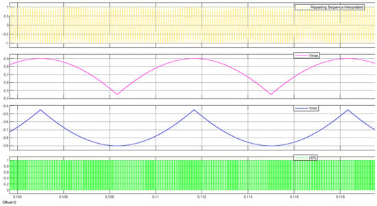
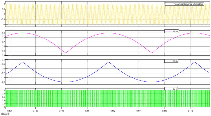
Figure 3 illustrates the shoot-through generation process of the conventional MBC strategy. The upper trace represents the carrier waveform, while the middle traces show the upper and lower threshold signals (Vmax and Vmin). The lower trace shows the generated shoot-through signal. It can be observed that the shoot-through pulses are generated directly from the carrier-threshold comparison and are immediately forwarded to the inverter gate generation stage.
Figure 3.
Shoot—through signal generated by the conventional MBC strategy.
3.2.3. Gate Signal Generation Stage
The generated shoot-through signal is combined with the conventional PWM switching signals using the logical OR and NOT gates to produce the six inverter gate signals (S1–S6). These gate signals are subsequently applied to the inverter switches to realise the conventional maximum boost control switching strategy, which serves as the benchmark for evaluating the proposed MMBC controller.
3.3. Proposed Modified Maximum Boost Control (MMBC)
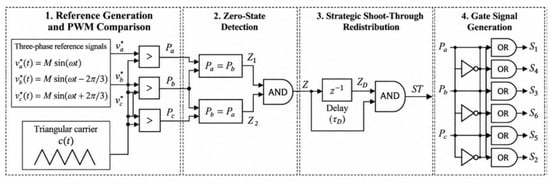
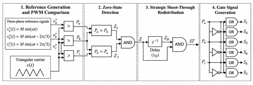
Unlike the conventional MBC strategy, where the shoot-through command is generated directly from the carrier-threshold comparison and applied to the gate generation stage, the proposed MMBC introduces an additional zero-state detection and logical processing network before the shoot-through command is generated. This additional stage strategically controls the temporal occurrence of the shoot-through intervals while retaining the overall MBC control objective.
The MATLAB/Simulink implementation of the proposed MMBC controller is illustrated in Figure 4.
Figure 4.
Proposed MMBC control logic.
3.3.1. Reference Comparison Stage
The reference comparison stage establishes the three-phase carrier-based PWM switching signals used as the input to the proposed MMBC zero-state detection stage.
where M is the modulation index and ω = 2πf1 is the fundamental angular frequency.
The PWM switching function is defined as
Equation (20) compares each sinusoidal reference with the common triangular carrier vcar(t) and generates the binary switching functions Pa, Pb, and Pc. These signals define the instantaneous PWM switching state of each phase leg and are subsequently used for zero-state detection.
3.3.2. Zero-State Detection Stage
The zero-state detection stage identifies the intervals in which the three inverter legs occupy either of the conventional zero switching states, 000 or 111.
The two conditions are combined as
Z [t] = Z1[t] ∧ Z2[t]
Equations (21) and (22) determine whether adjacent phase switching functions have identical states. Equation (23) produces a zero-state signal only when Pa = Pb = Pc. Therefore, Z(t) = 1 corresponds to the availability of a conventional zero state, either 000 or 111, which provides the basis for the subsequent strategic shoot-through generation.
3.3.3. Strategic Shoot-Through Redistribution Stage
The strategic shoot-through redistribution stage modifies the temporal position of the shoot-through command by processing the detected zero-state signal through a controlled delay and logical operation.
Then:
where τd is the delay introduced by the implemented delay block.
Zd(t) = Z (t − τd)
ST [t] = Z[t] ∧ Zd[t]
The implemented delay is one discrete simulation sample, such that , while the inverter switching period is Tsw = 1/fsw = 100 μs.
Equation (24) represents the delayed zero-state signal, while Equation (25) generates the strategic shoot-through command by logically combining the original and delayed zero-state signals. Consequently, the MMBC controller determines the occurrence of shoot-through from the detected zero-state intervals rather than directly from the carrier-envelope comparison used in conventional MBC. The modification therefore acts on the temporal placement of the shoot-through intervals while retaining the underlying MBC operating principle.
The logical relationship defined by (25) is summarised by the truth table in Table 2, showing that the shoot-through command is asserted only when both the instantaneous and delayed zero-state signals are active.
Table 2.
Truth table for the MMBC shoot-through condition.
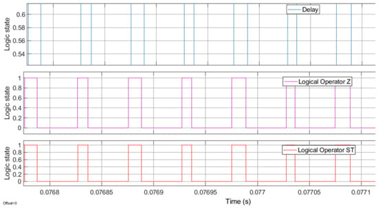
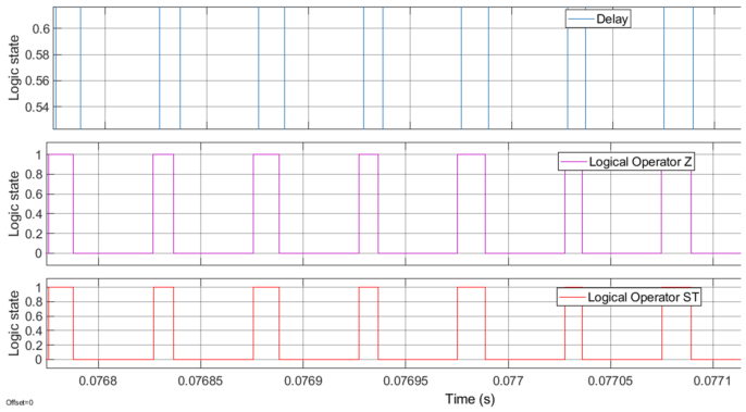
Figure 5 illustrates the signal-processing sequence used to generate the strategic shoot-through command in the proposed MMBC controller. The upper trace represents the delayed zero-state signal Zd(t), the middle trace represents the logically processed zero-state signal, and the lower trace shows the resulting shoot-through command ST(t). The figure demonstrates that the shoot-through command is generated through the proposed zero-state detection and delayed logical processing rather than directly from the carrier-threshold comparison used in conventional MBC. The resulting ST command is generated only when both the present and delayed zero-state conditions are active; therefore, the delayed ST interval is constrained by the detected zero-state availability. The theoretical MBC shoot-through duty ratio is retained as the reference value for comparison, while the proposed MMBC logic modifies the temporal placement and effective duration of the shoot-through intervals within the available zero-state intervals.
Figure 5.
Strategic shoot-through signal generated by the proposed MMBC strategy.
However, because the MMBC shoot-through command is obtained from the logical AND operation between the instantaneous and delayed zero-state signals, the effective shoot-through duration is determined by their temporal overlap. Consequently, the implemented MMBC may produce an effective shoot-through duty ratio lower than the theoretical MBC reference value. This effective reduction is dependent on the duration and timing of the available zero-state intervals and is therefore not a fixed percentage of the theoretical duty ratio. At the selected switching frequency of 10 kHz, the switching period is Ts = 100 μs while the implemented delay is τ = 10 μs, corresponding to 0.1 Ts. For M = 0.9, the theoretical MBC shoot-through duty ratio calculated from (5) is D0 = 0.5038. From the simulated MMBC shoot-through signal, the effective shoot-through duration was measured as TST = 14.062 μs, corresponding to an effective shoot-through duty ratio of DST = 0.1406. Thus, the delay introduces a temporal displacement equal to 10% of one switching period. The resulting effective shoot-through duration is governed by the overlap between the original and delayed zero-state intervals rather than by the delay value alone.
3.3.4. Gate Signal Generation Stage
The strategically generated shoot-through signal is combined with the conventional PWM switching signals using the logical OR and NOT gates to produce the six inverter gate signals (S1–S6). These gate signals are subsequently applied to the inverter switches to realise the proposed MMBC switching strategy.
The proposed MMBC is implemented using carrier-based PWM. Therefore, no separate space-vector dwell-time calculation or phase-leg selection procedure is required. The shoot-through intervals are generated through zero-state detection, logical processing, and the delay stage, which determine the temporal insertion of shoot-through states within the existing MBC switching sequence.
3.4. Comparison Between Conventional MBC and Proposed MMBC
Table 3 summarises the principal differences between the conventional maximum boost control (MBC) strategy and the proposed modified maximum boost control (MMBC). Although both controllers employ the same carrier-based PWM framework, inverter topology and switching frequency, they differ fundamentally in the generation and temporal placement of the shoot-through states.
Table 3.
Summarises the principal differences between MBC and MMBC.
As shown in Table 3, the proposed MMBC retains the converter topology, switching frequency, and overall MBC operating framework. The principal modification is confined to the shoot-through generation stage, where zero switching states are detected, logically validated, and delayed before insertion into the PWM sequence. Thus, the hardware implementation and fundamental control framework remain unchanged, with only the temporal location of the shoot-through intervals being modified.
4. Results and Discussion
The conventional MBC and proposed MMBC strategies were evaluated under identical simulation conditions. The modulation index was varied from M = 0.6 to M = 1.0, while the DC input voltage was maintained at 600 V. The theoretical boost factor and corresponding DC-link voltage were calculated from the established MBC relationships, whereas the fundamental phase-voltage magnitude and voltage total harmonic distortion (THDV) were obtained from the steady-state MATLAB/Simulink simulations using the MATLAB Powergui FFT analysis tool. Both controllers were evaluated using the same switching frequency, impedance-network parameters, load conditions, and simulation framework to enable a consistent comparison.
4.1. Output Voltage Waveform Analysis
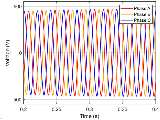
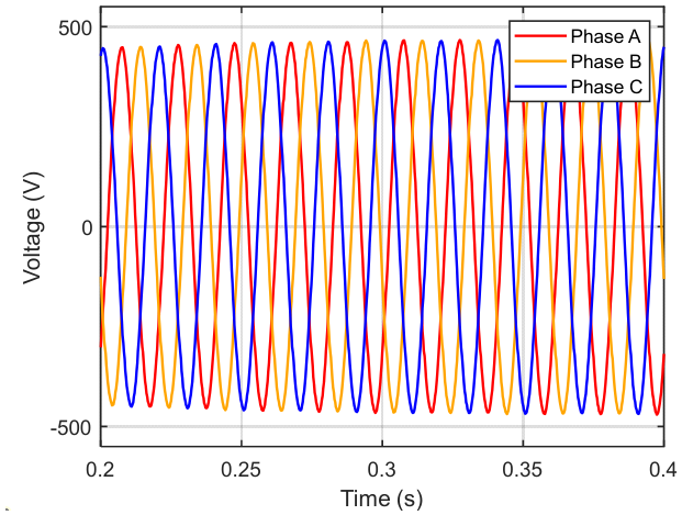
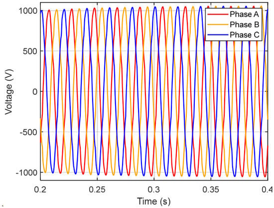
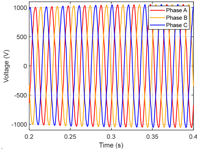
Figure 6 presents the steady-state three-phase output voltage waveforms obtained using the proposed MMBC strategy, whereas Figure 7 shows the corresponding output waveforms generated by the conventional MBC controller. The waveforms were obtained at an input voltage of 600 V and a modulation index of M = 0.9, selected to provide suitable operating conditions for evaluating the inverter performance.
Figure 6.
Three—phase output voltage using the proposed MMBC at M = 0.9.
Figure 7.
Three—phase output voltage using the conventional MBC.
Both controllers maintain balanced three-phase operation, while the proposed MMBC produces a lower fundamental output voltage magnitude than conventional MBC under the same operating conditions. However, noticeable differences are observed in both the waveform quality and the output voltage magnitude. The proposed MMBC produces a smoother and more sinusoidal output waveform with visibly reduced waveform distortion. At the same time, the output voltage magnitude is lower than that obtained using the conventional MBC strategy under identical simulation conditions.
Unlike the conventional MBC implementation, which generates shoot-through intervals whenever zero switching states become available, the proposed MMBC strategically redistributes these intervals within the PWM switching sequence. Although the theoretical MBC shoot-through duty ratio is retained as the operating reference, the modified temporal placement influences the interaction between the switching sequence and the fundamental output voltage component. Consequently, the proposed strategy achieves improved waveform quality while altering the effective output voltage magnitude.
The observations obtained from the output waveforms indicate that strategic shoot-through placement affects not only the harmonic characteristics of the inverter output but also the voltage utilisation achieved under maximum boost control. This demonstrates that the temporal distribution of shoot-through intervals influences the harmonic characteristics and voltage utilisation of the Z-source inverter.
4.2. Electrical Performance Analysis
The electrical performance of both control strategies was evaluated over a modulation index range of 0.6–1.0 while maintaining a constant DC input voltage of 600 V. The theoretical boost factor and corresponding DC-link voltage calculated from the conventional MBC relationship are summarised in Table 4 and Table 5. The fundamental phase-voltage magnitude reported in the tables corresponds to the peak magnitude of the 50 Hz component obtained from the FFT analysis of the simulated phase-to-ground output voltage and is therefore not an RMS quantity. The boost factor values were calculated from (6), while the corresponding theoretical DC-link voltages were determined from (8). The simulated fundamental phase-voltage magnitude and THDV are reported separately to distinguish the analytical operating point quantities from the simulated output voltage performance.
Table 4.
Electrical performance of the proposed MMBC.
Table 5.
Electrical performance of the conventional MBC.
Although the simulated fundamental phase-voltage magnitude increased with increasing modulation index, the proposed MMBC produced a lower fundamental output voltage magnitude than conventional MBC under the same operating conditions. This observed difference indicates that the temporal placement of the shoot-through intervals affects the fundamental output voltage utilisation, even when the same theoretical MBC boost factor relationship is used as the operating reference.
The corresponding electrical performance obtained using the conventional MBC strategy is presented in Table 5.
Table 5 reports the boost factor values calculated from the conventional MBC relationship in (6), showing the expected decrease in boost factor as the modulation index increases. The controller achieved a minimum THDV of approximately 4.05% at a modulation index of 0.9. Compared with the conventional MBC, the conventional controller produced a higher output voltage but also exhibited considerably greater harmonic distortion.
A direct comparison of Table 4 and Table 5 shows that the proposed MMBC reduces THDV by approximately 57.3%, from 4.05% for conventional MBC to 1.73% for MMBC at M = 0.9. This improvement in harmonic performance is accompanied by a reduction in the fundamental output voltage magnitude, indicating a trade-off between harmonic suppression and voltage utilisation.
4.3. Harmonic Spectrum Analysis
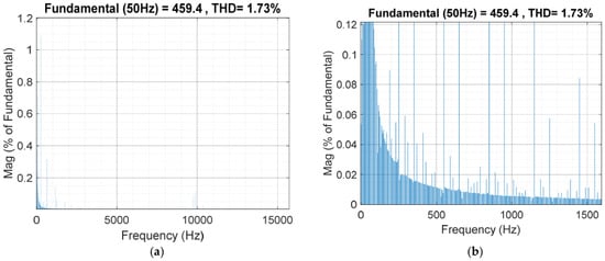
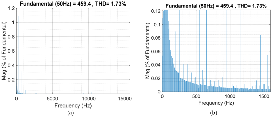
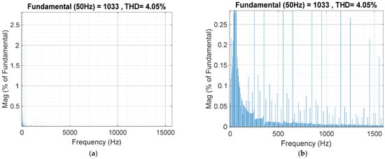
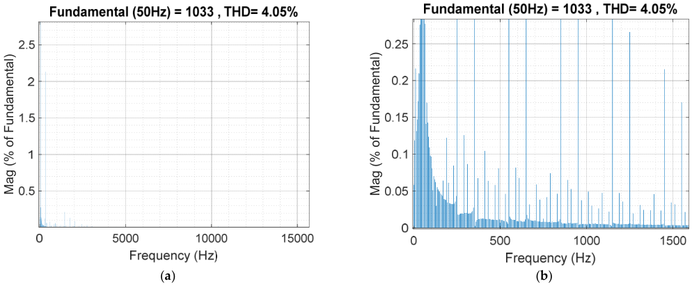
The output voltage harmonic spectra obtained using Fast Fourier Transform (FFT) analysis are presented in Figure 8 and Figure 9 for the proposed MMBC and conventional MBC, respectively. The FFT analysis was performed at a modulation index of 0.9, corresponding to the minimum-THD operating point identified from the parametric analysis presented in Table 4 and Table 5. The inverter was simulated using a discrete solver with a simulation sample time of 1 × 10⁻⁷ s. The phase-to-ground output voltage waveform supplied to the FFT Analyzer was sampled at an interval of 1 × 10⁻⁵ s, corresponding to a sampling frequency of 100 kHz and a Nyquist frequency of 50 kHz.
Figure 8.
(a) FFT spectrum of the proposed MMBC (M = 0.9). (b) Enlarged view of the low-frequency harmonic spectrum of the proposed MMBC (M = 0.9).
Figure 9.
(a) FFT spectrum of the conventional MBC (M = 0.9). (b) Enlarged view of the low-frequency harmonic spectrum of the conventional MBC (M = 0.9).
The FFT analysis was performed over 10 fundamental cycles beginning at 0.2 s, with a fundamental frequency of 50 Hz. The maximum displayed frequency was set to 15 kHz, and the maximum THD frequency was set equal to the maximum displayed frequency. Consequently, the voltage THD was calculated over the selected 0–15 kHz analysis bandwidth. This bandwidth encompasses the low-order harmonic components, the approximately 1.59 kHz LCL-filter resonance region, and the 10 kHz inverter switching-frequency component and its spectral components occurring within the selected bandwidth.
Using identical FFT conditions for both modulation strategies, the conventional MBC produced a fundamental phase-voltage peak of 1033 V with a voltage THD of 4.05%, whereas the proposed MMBC produced a fundamental phase-voltage peak of 459.4 V with a voltage THD of 1.73%. The comparison therefore uses the same sampling frequency, analysis interval, fundamental frequency, and THD bandwidth for both controllers.
The increased sampling frequency provides sufficient Nyquist bandwidth to capture the 10 kHz switching-frequency component and its associated spectral components, while the selected 0–15 kHz analysis range provides the bandwidth used for the reported THDV calculation. The harmonic spectra were evaluated over the selected 0–15 kHz range to assess the effect of the proposed shoot-through placement strategy on the harmonic content of the phase-to-ground output voltage.
The FFT spectrum of the proposed MMBC (Figure 8a) shows a dominant fundamental frequency component at 50 Hz together with a voltage total harmonic distortion (THDV) of 1.73%, while the enlarged low-frequency spectrum in Figure 8b provides improved visibility of the lower-order harmonic components. In comparison, the conventional MBC (Figure 9a) exhibits a THDV of 4.05% under identical operating conditions, with the corresponding low-frequency harmonic components shown in the enlarged view in Figure 9b.
The FFT results are consistent with the numerical results presented in Table 4 and Table 5, and the same 1.73% and 4.05% THD values are obtained under the defined analysis conditions.
The observed reduction in harmonic distortion can be attributed to the strategic redistribution of shoot-through intervals within the PWM switching sequence. Rather than modifying the converter topology or introducing additional switching devices, the proposed MMBC alters only the temporal placement of the shoot-through states. This redistribution changes the harmonic content of the inverter output while retaining the fundamental operating mechanism of maximum boost control.
However, the improved harmonic performance is accompanied by a reduction in output voltage compared with the conventional MBC. Although the overall shoot-through mechanism remains unchanged, relocating the shoot-through intervals influences the effective utilisation of the boosted DC-link voltage under the investigated operating conditions. Consequently, the proposed MMBC demonstrates a trade-off between harmonic suppression and voltage utilisation.
Overall, the results demonstrate that the temporal placement of shoot-through intervals has a significant influence on the harmonic behaviour of Maximum Boost-Controlled Z-source inverters. The proposed MMBC achieves lower output voltage harmonic distortion without modifying the inverter topology or introducing additional hardware, thereby providing an alternative PWM strategy for applications where improved output power quality is a primary design objective.
5. Conclusions
This paper presented a comparative performance analysis of conventional maximum boost control (MBC) and the proposed modified maximum boost control (MMBC) for a three-phase Z-source inverter. The proposed MMBC strategically redistributes the shoot-through intervals within the conventional PWM switching sequence while maintaining the same converter topology, switching frequency, and theoretical MBC shoot-through duty ratio.
Both control strategies were evaluated in MATLAB/Simulink under identical operating conditions. The results demonstrate that the temporal placement of the shoot-through intervals influences the harmonic characteristics and fundamental output voltage magnitude of the inverter. At M = 0.9, the proposed MMBC achieved a minimum voltage total harmonic distortion (THDV) of approximately 1.73%, compared with 4.05% for conventional MBC under the same operating conditions. This corresponds to an approximate 57.3% reduction in voltage harmonic distortion. The improved harmonic performance was accompanied by a lower simulated fundamental phase-voltage magnitude compared with conventional MBC, demonstrating a trade-off between harmonic suppression and output voltage utilisation.
The results therefore indicate that strategic shoot-through placement can improve the voltage harmonic performance of the Maximum Boost-Controlled Z-source inverter without modifying the converter topology or introducing additional switching hardware. The observed reduction in harmonic distortion is obtained through modification of the temporal placement of the shoot-through intervals within the PWM switching sequence, while maintaining the same converter topology and switching frequency, with the theoretical MBC shoot-through duty ratio retained as the operating reference.
The present investigation is limited to simulation-based evaluation of output voltage harmonic performance and does not include output-current THD (THDI), impedance-network current and capacitor-voltage ripple, conversion efficiency, switching losses, semiconductor voltage and current stresses, transient response, parameter sensitivity, or experimental/hardware-in-the-loop validation. Accordingly, the conclusions of this study are limited to the simulated fundamental phase-voltage magnitude and voltage THDV under the investigated operating conditions.
Future work will investigate the influence of strategic shoot-through placement on output-current harmonic distortion (THDI) and the associated impedance-network current and capacitor-voltage ripple. Further studies will examine the performance of the proposed MMBC under different load conditions and operating points, including its effects on semiconductor stress, switching losses, efficiency, and dynamic performance. Experimental or hardware-in-the-loop validation will also be considered to further assess the proposed strategy under practical operating conditions.
Author Contributions
Conceptualization, M.S.P.N. and T.R.J.; methodology, T.R.J.; software, T.R.J.; validation, T.R.J., M.K. and M.S.P.N.; formal analysis, T.R.J.; investigation, T.R.J.; resources, T.R.J.; data curation, T.R.J.; writing—original draft preparation, T.R.J.; writing—review and editing, T.R.J.; visualization, T.R.J.; supervision, M.K., M.S.P.N.; project administration, T.R.J.; funding acquisition, M.K. All authors have read and agreed to the published version of the manuscript.
Funding
This research was funded by Durban University of Technology. The APC was funded by Durban University of Technology.
Data Availability Statement
The data supporting the findings of this study are contained within the article.
Conflicts of Interest
The authors declare no conflict of interest.
References
- Gyawali, B.; Ajmal, A.M.; Liu, W.; Yang, Y. A review on modulation techniques of quasi-Z-source inverter for grid-connected photovoltaic systems. E-Prime-Adv. Electr. Eng. Electron. Energy 2024, 10, 100809. [Google Scholar] [CrossRef] [Scilit]
- Rauf, T.; Furqan, M.; Zulifqar, S.; Rafiq, S. Implementation and performance analysis of Z source inverter with space vector PWM technique with low THD factor and high gain. J. Electr. Electron. Eng. 2022, 10, 95–103. Available online: https://www.sciencepublishinggroup.com/article/10.11648/j.jeee.20221003.14 (accessed on 4 October 2026).
- Peng, F.Z. Z-source inverter. IEEE Trans. Ind. Appl. 2003, 39, 504–510. [Google Scholar] [CrossRef] [Scilit]
- Peng, F.Z.; Shen, M.; Qian, Z. Maximum boost control of the Z-source inverter. IEEE Trans. Power Electron. 2005, 20, 833–838. [Google Scholar] [CrossRef] [Scilit]
- 519-2022; IEEE Standard for Harmonic Control in Electric Power Systems. IEEE Power and Energy Society: Montréal, QC, Canada, 2022. [Google Scholar] [CrossRef] [Scilit]
- Xu, W.; Chan, C.H.; Chan, K.W.; Or, S.W.; Ho, S.L.; Liu, M. A quantitative harmonics analysis approach for sinusoidal pulse-width-modulation based Z-source inverters. IET Power Electron. 2022, 15, 815–824. [Google Scholar] [CrossRef] [Scilit]
- Shen, M.; Wang, J.; Joseph, A.; Peng, F.Z.; Tolbert, L.M.; Adams, D.J. Constant boost control of the Z-source inverter to minimize current ripple and voltage stress. IEEE Trans. Ind. Appl. 2006, 42, 770–778. [Google Scholar] [CrossRef] [Scilit]
- Pires, V.F.; Cordeiro, A.; Foito, D.; Roncero-Clemente, C.; Romero-Cadaval, E.; Silva, J.F. Improved carrier-based modulation for the single-phase T-type qZ-source inverter. Electronics 2024, 13, 1113. [Google Scholar] [CrossRef] [Scilit]
- MathWorks. MATLAB and Simulink; MathWorks: Natick, MA, USA; Available online: https://www.mathworks.com/products/simulink.html?utm_source=chatgpt.com (accessed on 22 January 2025).
- Abdelhakim, A.; Blaabjerg, F.; Mattavelli, P. Modulation Schemes of the Three-Phase Impedance Source Inverters—Part I: Classification and Review. IEEE Trans. Ind. Electron. 2018, 65, 6309–6320. [Google Scholar] [CrossRef] [Scilit]
- Abdelhakim, A.; Blaabjerg, F.; Mattavelli, P. Modulation Schemes of the Three-Phase Impedance Source Inverters—Part II: Comparative Assessment. IEEE Trans. Ind. Electron. 2018, 65, 6321–6332. [Google Scholar] [CrossRef] [Scilit]
- Husev, O.; Roncero-Clemente, C.; Romero-Cadaval, E.; Vinnikov, D.; Jalakas, T. Three-level three-phase quasi-Z-source neutral-point-clamped inverter with novel modulation technique for photovoltaic application. Electr. Power Syst. Res. 2016, 130, 10–21. [Google Scholar] [CrossRef] [Scilit]
- Hossameldin, A.A.; Abdelsalam, A.K.; Ibrahim, A.A.; Williams, B.W. Enhanced Performance Modified Discontinuous PWM Technique for Three-Phase Z-Source Inverter. Energies 2020, 13, 578. [Google Scholar] [CrossRef] [Scilit]
- Siwakoti, Y.P.; Peng, F.Z.; Blaabjerg, F.; Loh, P.C.; Town, G.E.; Yang, S. Impedance-source networks for electric power conversion part II: Review of control and modulation techniques. IEEE Trans. Power Electron. 2015, 30, 1887–1906. [Google Scholar] [CrossRef] [Scilit]

Disclaimer/Publisher’s Note: The statements, opinions and data contained in all publications are solely those of the individual author(s) and contributor(s) and not of MDPI and/or the editor(s). MDPI and/or the editor(s) disclaim responsibility for any injury to people or property resulting from any ideas, methods, instructions or products referred to in the content. |
© 2026 by the authors. Licensee MDPI, Basel, Switzerland. This article is an open access article distributed under the terms and conditions of the Creative Commons Attribution (CC BY) license.