


Abstract
Electric vehicles (EVs) have sparked global awakening in their ability to lower greenhouse gas emissions and reliance on fossil fuels. The traction motor and associated electronic power converters have a strong impact on the performance and reliability of EVs. Switched reluctance motors (SRMs) have emerged as a substitute for EVs owing to their simple and robust construction, devoid of rotor windings and permanent magnets, high fault tolerance, wide speed range, and resilience to rugged operating conditions. Their applicability for electric traction has been impaired by torque density, excessive torque ripples, and acoustic noise. Conventional EVs use two converters, each for charging and traction, which increase the vehicle’s cost, weight, and volume. Footprints of contemporary integrated battery charger (IBC) configurations are dissuaded by high component count, complex control mechanisms, and restrictive bidirectional operation. This paper proposes a multimode, reconfigurable IBC–integrated switched reluctance motor (SRM) drive, operable in traction, Grid-to-Vehicle (G2V), and Vehicle-to-Grid (V2G) modes. The proposed configuration reuses the SRM phase windings as grid-side inductors during G2V and V2G modes, thereby eliminating a separate dedicated grid-side charging inductor stage and extra charging power conversion stage. The simulation model employs a three-phase 6/4 SRM, whereas the laboratory prototype employs a three-phase 12/8 SRM. The proposed reconfigurable integrated battery charger was evaluated in traction mode using sliding-mode control, model-predictive control, and proportional–integral hysteresis control. For a 1500 rpm speed reference, sliding-mode control achieved the best dynamic response, reducing the rise time and settling times to 14 s and 24 s, respectively, compared with 47 s and 78 s for proportional–integral hysteresis control. It reduced the torque ripple coefficient from 1.31 to 0.020, while model-predictive control achieved 0.0168, with an increased algorithmic computational burden associated with online prediction and optimization. Experimental results establish effective operation in traction, G2V, and V2G modes under the tested laboratory conditions, with a measured power factor of approximately 0.90 and current THD of 3.3% in G2V and 5.2% in V2G modes.
1. Introduction
Compared to traditional internal combustion engine (ICE)-based vehicles, which run on fossil fuels and emit harmful pollutants like carbon monoxide, nitrous oxides, particulate matter, and greenhouse gases (GHGs), electric vehicles (EVs) have shown great promise [1]. The switchover to EVs can reduce air pollution, greenhouse gas emissions and also reduce dependence on finite fossil fuel resources. [2]. EVs have better source-to-wheel efficiency, quicker dynamic response, higher power-to-weight ratio and torque over a broad speed. Their limited driving range, long charging duration, and degraded battery service life deter their wide adoption in the automotive industry [3]. The choice of traction motor directly influences drivetrain performance by determining the available torque–speed characteristics, acceleration capability, energy efficiency, power density, overall cost, and thermal management requirements.
Motor selection also affects the inverter rating, battery current demand, reliability, and the use of critical materials such as rare-earth magnets. Induction motors (IMs) are prodded by their rugged construction, reliability, and low cost. However, their performance is limited by higher copper and core losses, lower efficiency, low power factor, and reduced inverter utilization factor, especially under partial load driving range conditions. [4]. Permanent magnet synchronous motors (PMSMs) are better alternatives as they are efficient over a wide operating range, compact in size, and have better heat management due to lower rotor losses. Yet PMSMs are less preferred due to rare-earth magnets, daunted by high component costs, corrosion susceptibility and demagnetization at elevated temperatures [5,6]. Previous studies have highlighted switched reluctance motors (SRMs) as promising traction motor options for EVs, because of their low manufacturing cost, high torque-per-ampere capability, fast dynamic response, and reliable operability at high speeds and elevated temperatures. Nonetheless, torque ripple, electromagnetic interference, and acoustic noise are deterrents to their universal deployment in EVs [7].
Traditional EV drivetrains employ customized power converters for battery charging and propulsion, which intensifies the complexity, weight, and price. Integrated battery chargers (IBCs) tackle these constraints by the integration of traction and charging modes into a single electronic power converter [8]. Desirable control features of a high power factor, constant-current (CC)/constant-voltage (CV) (CC/CV) charging and minimum torque ripple pose intricate challenges. The additional requirement to support Grid-to-Vehicle (G2V) charging and Vehicle-to-Grid (V2G) power export exacerbates the complexity of the IBC control scheme, as it must ensure bidirectional power flow while maintaining battery charging performance, grid current quality, and compliance with grid-interconnection regulations [9].
Existing SRM-based IBC systems comprise a large number of components, resulting in increased drive costs and low system reliability. The majority of the reported solutions focus on either the converter topology or control strategy, excluding the option for a co-designed power electronics and control scheme for multi-mode functions. Achieving a transition between motoring, G2V, and V2G modes with minimal torque ripple and grid-compliant power quality is a significant challenge. Moreover, there is a dearth of reports on experimental validation of such integrated systems under operational conditions.
2. Related Works
IBC mitigates the shortcomings of on-board charging systems (OBCSs) and off-board charging systems (OFBCSs), as it enables the on-board motor drive circuit to double up as a charger devoid of additional hardware, resulting in diminished EV manufacturing costs [10]. The SRM motor windings function as energy-storing inductors which minimize the usage of large magnetic components. Stacked against IM- and PMSM-based IBCs, SRM-based IBC offers the following benefits:
- Inherent charging function: OBC is made possible by redesign of the power electronics that drive the SRM. In contrast, PMSM/IM-based IBC calls for additional inverter and rectifier circuitry for charging or hardware switching, aggravating design complexity, size, and cost.
- Converter flexibility and fault tolerance: The SRM is extremely fault-tolerant due to its independent phase windings and simpler switching scheme. Each phase winding is electrically and magnetically isolated from the other phase windings. SRMs continue to function with a single-phase failure, unlike PMSMs impacted by failure of a single stator winding.
- Performance at high temperatures: Demagnetization risk in the wake of extreme heat stress is a cause of concern in PMSMs, affecting IBC’s thermal stability.
- Performance and speed range: SRMs fare better in driving and generating (charging) modes, aided by a wide region of constant power and excellent torque at low speeds. PMSMs are compromised by constant power region and rotor losses at low speeds, impacting efficiency. In this work, low-speed operation refers to the region from standstill to approximately 20–30% of the motor base speed. For a typical EV traction motor with a base speed of 3000–4000 rpm, this corresponds to 0–1000 rpm, where high torque is required for vehicle starting, acceleration, and hill-climbing operation.
- Easier control in charging mode: The SRM drives function with unidirectional current which simplifies the charging control strategy and provides simpler transition from drive operation to charging mode.
Multifunctional drives that reuse the SRM phase windings and converter to charge the battery provide inherent simplification by precluding dedicated OBC hardware. Several existing topologies have downsides of higher switch counts, increased manufacturing expenses, and unwieldy control mechanisms.
Motivated by minimized hardware redundancy and increased system efficiency, incorporation of SRM-driven battery charging capabilities into EV traction drives has stimulated perceptible research interest. Early research demonstrated that existing SRM phase windings and converter topologies could be utilized for onboard battery charging without requiring significant hardware modifications. However, these methods have extensive electrical or mechanical reconfiguration devices, contactors, and relays, which impede mode transition, and compromise reliability. Through coordinated control techniques and converter reconfiguration, various topologies accomplished multi-mode operation and bidirectional power flow (traction, V2G, G2V). These advancements were derated by switching complexity, control coordination, and stability during mode transitions.
In [11], a front-end voltage boosting converter was presented without extra inductances at the expense of additional switches to generate voltages higher than the battery supply, which enabled functionality at high speeds (6000–12,000 rpm). A split-converter configuration for a four-phase SRM offering integrated charging functionality from AC and DC sources was presented in [12]. This circuit configuration involves a trade-off of improved fault tolerance against a larger number of switches and center-tapped windings, complicating practical implementation. In [13], an integrated SRM drive was proposed using two three-phase intelligent power modules (IPMs) at the front end and the machine side, utilizing machine winding inductances as input filters. In [14], a tri-port modular SRM drive for hybrid EVs (HEVs) was introduced, combining the generator, battery, and SRM. The design required additional switches and center-tapped winding connections, increasing the converter cost, control complexity, gate-driver circuitry, and wiring requirements, thereby making practical implementation more challenging.
In [15], an integrated SRM drive boosting OBC functionality was reported utilizing an asymmetric half-bridge converter with three junction relays and two battery packs. Nevertheless, this design entails difficult hardware overhead. A simpler integrated SRM topology with fewer switches was implemented in [16], although it was more susceptible to faults. A modular tri-port high-power SRM drive for PHEVs was designed in [17] using eight switches per SRM phase winding, increasing cost and complexity. In [18,19], multilevel bidirectional SRM converters were developed for HEVs, relying on various battery bank connections. These topologies had the capability to increase the DC voltage, improving the energization and demagnetization dynamics of the SRM. The complicated front-end control for the converter restricts practical feasibility. In [20], a multiport converter with reduced capacitance r was developed, employing switch multiplexing. Yet the lack of charging functionality impaired its suitability for integrated EV systems. In [21], a bidirectional two-quadrant front-end DC/DC converter with an asymmetric bridge circuit was proposed, enabling G2V, Vehicle-to-Home (V2H), and V2G features. The design employed additional filter inductors and capacitors, increasing the hardware footprint, cost, and power losses. In [22], a Modular Multilevel Converter (MMC)-based SRM drive with decentralized battery energy storage for HEVs was presented. This configuration allows for multiple operational modes, together with enhanced fault tolerant drive capability, but the higher switch count circuit imposes higher cost and implementation complexities. Despite successful integration of charging and driving modes of existing SRM topologies, the downsides were escalated component counts, degraded fault tolerance, poor power quality, and restricted interoperability with standard SRM drives.
This review indicates that although SRM-based IBCs exhibit the possibilities for hardware reuse, extant designs involve complex circuitry and ineffective mode transitions. Efforts to surmount their constraints through auxiliary switching or passive components invariably require additional hardware and rarely enable bidirectional power flow. The summarized evaluation in Table 1 and Table 2 signifies that existing SRM-based IBC configurations entail complex converter architectures with increased component counts: numerous switches, relays, passive components, or center-tapped windings to support charging functionality. The increased component count inevitably leads to conduction losses, implementation cost, and control complexity. Barely 2 of the 16 topologies reported support both G2V and V2G operations, as the bulk of the systems are restricted to unidirectional G2V charging. Although several topologies achieve an acceptable power factor or low current harmonic distortion, these enhancements are at the expense of supplementary hardware. None of the deployed topologies address torque ripple mitigation and bidirectional power transfer.
Table 1.
Reported electrical performance and experimental validation from literature.
Table 2.
Structural and functional comparison of proposed SRM-based IBC with existing topologies from literature.
In contrast, the proposed three-phase SRM-based IBC achieves traction, regenerative braking, G2V, and V2G operation using only the conventional six-switch asymmetric half-bridge converter and three Single-Pole Double-Throw (SPDT) relays. The proposed configuration also provides a good power factor with low harmonic distortion, simple renewable energy integration, and incorporates torque ripple mitigation, thereby offering a simpler and more comprehensive solution than existing SRM-based IBC topologies. The main contributions of this paper are summarized as follows:
- Reconfigurable SRM-based IBC unifies driving and charging modes, using a single converter obviating separate propulsion and charging units. During grid-connected mode, the SRM phase windings are reutilized as grid-side inductive elements, removing the requirement for a distinct dedicated charging inductor stage and an additional charging converter.
- The lower component count for the IBC configuration, suitable for single and three-phase grid setups, leads to compact cost-effective system design and enhanced power density.
- The hybrid control framework handles dual-propulsion and grid-interfaced modes, ensuring low torque ripple during motoring, low harmonic distortion and a good operating power factor for bidirectional (G2V/V2G) operations.
- The modular SRM-drive architecture is scalable for dual single- and three-phase grid configurations, enabling flexible deployment in EV applications.
- Comparative evaluation of contemporary topologies focuses on operational flexibility, decreased component count and manufacturing cost.
Though various SRM-based IBC configurations have established the reuse of the traction converter and/or motor windings for G2V and V2G operation, the proposed topology varies in the method in which the existing SRM asymmetric half-bridge is reconfigured for bidirectional grid interaction. In the proposed configuration, the same six-switch asymmetric half-bridge utilized for SRM traction is engaged for the grid-connected operating modes, while three SPDT relays govern the electrical connection of the three SRM phase windings. During G2V and V2G modes, the relay arrangement disengages the motor phases from the traction path and connects the SRM windings to the grid interface, enabling the windings to realize the inductive function for grid current control.
The comparison in Table 1 and Table 2 reflects the number of active switches, diodes, relays, dedicated inductive components and additional conversion stages. For a consistent comparison, the reviewed topologies are assessed using structural parameters and reported performance indices separately. Parameters not openly stated in the cited literature are represented as NA (not addressed) rather than being estimated.
3. Proposed SRM-Based Reconfigurable Integrated Battery Charger
This section presents the proposed SRM-based reconfigurable IBC, which facilitates traction, G2V, and V2G operations using a single asymmetric half-bridge converter, with minimal hardware modifications. First, the converter topology and its reconfiguration mechanism are described, followed by the operating principles of the converter in traction, explanation of G2V and V2G modes, and the switching sequences and power flow paths.
3.1. Topology Design
A bidirectional power interface between the three-phase AC grid and the EV battery (DC link) is established by connecting each of the three SRM phase windings (A, B, and C) to the AC grid through SPDT relays, as shown in Figure 1. The addition of SPDT relays to the common node between the junction of the two-phase switches (Q1–Q2, Q3–Q4, Q5–Q6), and the SRM phase winding terminals (LA, LB, LC) provide a three-phase interface for AC grid operations, enabling G2V and V2G modes. The proposed SRM based IBC comprises the following:
Figure 1.
Proposed SRM-based reconfigurable converter.
- Six MOSFET power switches (Q1–Q6) and six diodes (D1–D6), configured to form three asymmetric half-bridges.
- A battery pack providing the DC-link voltage, UAB, which serves as the primary energy source during traction operations and as the energy storage element during G2V charging and V2G power injection actions.
- A set of three SPDT relay switches (RA, RB, RC) for reconfiguring the converter topology between SRM driving, G2V and V2G modes.
In Figure 1, when the relay RA is in position 1, the relay links the phase winding LA directly between the top and bottom switches of each leg, and the drive operates in conventional asymmetric half-bridge mode, facilitating traction. In position 2, the RA relay reroutes the phases to the AC grid and the SRM windings act as line filters due to its inherent inductance. Logical isolation and functional change is accomplished using relay-level switching, which reduces the cost and overall losses. For the G2V/V2G modes, the control mechanism activates suitable switches to shape current waveforms for a high power factor, minimal harmonics, and grid-synchronized voltage injection. The mode selection logic confirms that only a single mode is active at any particular time with safety interlocks, averting shoot-through faults or simultaneous dual-mode operation.
In relay position 1, each winding is connected between the corresponding upper and lower converter switches, enabling conventional SRM traction operation. In relay position 2, the windings are disconnected from the traction converter and reconfigured as grid-side filter inductors, establishing a bidirectional power interface between the AC grid and the battery DC link (UAB) for both G2V and V2G operation. This reconfiguration facilitates hardware reuse by eradicating the requirement for a distinct dedicated charging inductor and charging stage, thereby minimizing the extra hardware associated with integrated charging. During G2V/V2G operations, the Q1–Q6 switches are controlled using sinusoidal pulse width modulation (PWM) (SPWM) to regulate grid current, maintain a high power factor with low current harmonic distortion, and control bidirectional power flow. The relay control logic ensures that only a single operating mode (traction, G2V, or V2G) is active at any instant in time, supplemented by electrical interlocks that prevent simultaneous relay actuation and shoot-through faults, ensuring safe and reliable operation.
3.2. Operating Principles of Proposed SRM-Based IBC
The battery provides energy to the SRM via the asymmetric bridge converter, shown in Figure 2. The control emphasis is on the commutation timing, speed–torque control and torque ripple mitigation. A battery pack, represented by the DC-link voltage UAB, supplies electrical energy to the SRM through the asymmetric half-bridge converter, as shown in Figure 2. The controller determines the phase commutation angles based on the rotor position to ensure proper phase excitation. Speed–torque control is achieved by regulation of the phase current, apropos of the desired operating conditions. Torque ripple is minimized by optimizing the commutation instants and current profiles during phase excitation and demagnetization. The operating sequence of each SRM phase (Phase A) constitutes three modes: excitation, freewheeling, and demagnetization, as indicated in Figure 3.
Figure 2.
Traction mode of proposed SRM-based IBC.
Figure 3.
Current paths during excitation, freewheeling, and demagnetization modes of the IBC.
In the excitation mode, the two switches (Q1 and Q2) are energized and current flows from the positive DC terminal of the UAB battery through Q1, through the phase winding (LA), and through Q2 to the ground. When the rotor is aligned in the position for phase A, the phase inductance is maximum, enabling an increase in current and magnetic energy. This builds up magnetic flux and produces positive torque. During the excitation mode, electrical energy is transferred from the battery pack (DC-link voltage UAB) through the asymmetric half-bridge converter to the energized SRM phase winding, producing the electromagnetic torque required for propulsion. During demagnetization, Q1 and Q2 switches are turned OFF, and the residual magnetic energy stored within the phase winding must be dissipated or recovered. Due to the inductive nature of the winding, the collapsing magnetic field will drive current through diodes D1 and D2 and return energy to the battery.
Both G2V and V2G modes utilize identical SPWM-derived gating signals, generating six switching intervals (0–60°, 60–120°, 120–180°, 180–240°, 240–300°, and 300–360°) over one electrical cycle of the three-phase grid voltage, as summarized in Table 3. In G2V mode, IBC functions as an active front-end (AFE) converter where the three-phase grid voltage is actively shaped to regulate the DC-link voltage for battery charging within the prescribed safety limits. During each 60° grid sector, two windings form the active power transfer path between the three-phase AC grid and the DC link, while the third winding provides the return leg through its lower switch or diode. Although the current direction reverses between G2V and V2G, the inductive actions of LA, LB, and LC remain the same.
Table 3.
Switching sequence and traced current paths of proposed SRM-IBC during grid-connected mode.
Table 3 summarizes the switching sequence of the proposed IBC during one electrical cycle of the three-phase grid voltage. The “Angle” column denotes the electrical angle (θ) of the grid voltage, divided into six 60° sectors corresponding to one complete 360° grid cycle. The “Conducting switches (ON)” column lists the upper and lower converter switches that are actively gated during each sector. The “Current flow paths” columns describe the principal conduction path of the instantaneous current in G2V and V2G modes. Here, UAB+ and UAB- represent the positive and negative terminals of the DC link, while LA, LB, and LC denote the SRM phase windings that are reutilized as grid-side inductive elements, as shown in Figure 4.
Figure 4.
Circuit configuration for grid-connected mode of proposed SRM-based IBC.
For example, during the 0–60° grid sector in G2V mode, Q1, Q5, and Q4 switches are gated ON. The grid current enters through phase windings LA and LC, passes through the upper switches Q1 and Q5, charges the DC link (UAB), and returns to the grid through the lower switch Q4 (or diode D4) and phase winding LB. Conversely, in V2G mode, the same switching state is maintained; however, the current direction reverses. Energy is delivered from the DC link through Q1 and Q5 to windings LA and LC, injected into the grid, and returns through winding LB and switch Q4. Similarly, during the 60–120° sector, switches Q1, Q4 and Q6 conduct.
4. Design of Proposed System
A detailed MATLAB/Simulink R2025a model was developed to evaluate the proposed topology under traction, G2V, and V2G operating modes and for the assessment of converter performance, power flow, and control functionality.
4.1. Simulation Validation
The hybrid control scheme selects the appropriate control strategy based on the operating state of the reconfigurable SRM-IBC by utilizing relay position sensing and real-time monitoring of the battery/DC-link voltage (UAB), grid voltage, phase currents, and rotor position. The simulation environment in Figure 5 replicates embedded control logic, power electronic switching, and energy flow, providing a scalable platform for firmware and prototype development. The simulation model provides simplified debugging and independent testing for the four main interconnected subsystems, the SRM, the IBC, the grid interface, and the control system, for the motor and the grid. Each subsystem is further split into functional blocks composed of physical components or control logic elements.
Figure 5.
Simulation model for testing in MATLAB/Simulink.
- The SRM model implements the mechanical properties of the motor, utilizing lookup tables for the nonlinear magnetization characteristics. It accounts for the dynamic behavior of the speed, phase current, flux linkage, and torque for various values of load torque applied.
- The IBC model interfaces the SRM with the AC grid and the DC link (battery). The IBC can be reconfigured to the operating mode: traction, G2V, or V2G. MOSFETs and freewheeling diodes manage the current conduction in the SRM windings. Logical switches facilitate easy reconfiguration of the topology and gate signals are generated by the PWM controller with appropriate dead-time insertion.
- The grid interface model depicts the three-phase AC supply and its interaction with the proposed IBC model during grid-connected operations. The grid is modeled as a three-phase voltage source with nominal voltage and frequency, with a series R–L equivalent impedance to signify the grid-side impedance. Voltage and current measurement blocks measure the grid-side electrical quantities, while a phase-locked loop (PLL) provides grid voltage synchronization for the controller. An LCL filter at the grid interface provides practical filtering of switching-frequency harmonics, smoothens the inverter-side current before grid interaction and should not be inferred as a dedicated charging inductor stage.
- The control system comprises two modules: the control scheme for motor torque-speed regulation and the grid tie controller involving direct-quadrature (dq)-axis control for active power exchange. During propulsion mode, the outer speed/torque controller generates phase current references, while the inner loops ensure accurate current tracking. In grid-connected mode, dq controllers manage active and reactive power. The battery State of Charge (SoC) is monitored to regulate charged/discharge current within the prescribed limit. Mode management logic supervises transitions between operational modes, enabling or disabling relevant control loops and routing the appropriate gating commands. The PWM logic processes these control signals and produces the synchronized gating pulses for the IBC switches, ensuring proper dead-time insertion.
- Signal flow: The input signals include rotor position/speed, grid voltage and current, battery voltage, and user command signals. The outputs consist of motor torque, speed and current waveforms and these signals enable real-time feedback to the controller.
The simulation time is set for 2 s and begins in traction mode with the IBC functioning as an asymmetric half-bridge converter, with a DC link/battery voltage of 240 V driving the SRM. At this stage, the coil-short switches comprising RA, RB and RC are engaged and the grid contactor/synchronization switch named G remains open, isolating the converter from the grid and preventing backflow of power. The controller operates in load-following mode to regulate motor performance.
During grid-connected operation, the coil-short switches comprising RA, RB and RC in Figure 5 are opened first, momentarily isolating both paths to prevent simultaneous conduction, shoot-through faults, or overcurrent. Once isolation is confirmed, the grid interface switch G is closed, and the IBC is reconfigured into a symmetric inverter for grid connection. The PLL locks to the grid voltage phase, enabling dq-based current control. A reference current is applied, positive for V2G and negative for G2V. The component will be set to zero for a close to unity power factor. A ramp generator gradually increases the current reference to prevent overshoot and saturation, while a limiter constrains it within safe operating limits.
The hardware reduction claim pertains to dedicated charging conversion elements related to the IBC topology. Practical grid-connected deployment may still need interface elements like filtering, DC-link voltage stabilization, isolation, sensing, protection, and reconfiguration mechanisms. These auxiliary elements are implementation-dependent and do not imply an extra charging power conversion stage.
The compensator block provides offset during the converter startup to nullify the zero-voltage decoupling delay; thereby preventing current spikes. Once the PLL achieves phase lock, the dq and inverse Clarke transformations provide synchronized current waveforms enabling power flow injection between the grid and battery. Mode transitions are managed by parameterized step inputs, enabling cost-effective hardware realization. During traction, the coil-short switches comprising RA, RB and RC in Figure 5 are engaged, and the grid contactor/synchronization switch G remains open, isolating the converter from the grid and preventing backflow of power.
During the transition from traction to grid-connected operation, the phase reconfiguration relays RA, RB, and RC (Figure 1) are first actuated to disconnect the SRM phase windings from the traction converter legs (Q1–Q6) and the grid interface, thereby temporarily isolating both the traction current path and the grid current path. This brief isolation interval prevents simultaneous conduction, shoot-through faults, and transient over currents during topology reconfiguration. As relay switching occurs only during operating mode transitions and not during PWM switching, conventional electromechanical SPDT relays are adequate, eliminating the need for high-speed relays, thereby reducing hardware complexity and cost. The converter controller continuously monitors the feedback on the relay positions to verify that RA, RB, and RC have reached their commanded positions, before enabling the grid interface relay (G). Once the relay status is confirmed, relay (G) connects the converter to the three-phase AC grid, reconfiguring the asymmetric half-bridge traction converter into a three-phase voltage-source inverter suitable for G2V and V2G operation.
The main simulation parameters are depicted in Table 4. The inductors and capacitor in the simulation model and Table 4 should be interpreted as auxiliary grid interface and DC-link filtering elements rather than extra topology-defining power conversion stages. The 5 mH inductors characterizes the grid-side filtering/interface settings, while the 1000 μF capacitor facilitates DC-link voltage stabilization in the simulation model. The LCL filter in the grid-connected simulation is considered an interface/filtering necessary to replicate the practical grid-connected mode rather than as a separate charging converter.
Table 4.
Parameters used for simulation.
4.2. Traction Mode
To identify the most suitable traction mode controller, three control strategies, sliding-mode control (SMC), model-predictive control (MPC), and proportional–integral (PI)-based hysteresis current control, were evaluated via the MATLAB/Simulink model of the proposed SRM-based IBC under identical operating conditions. Each controller was subjected to identical conditions to ensure a fair comparison: speed reference, load torque, motor parameters, and converter switching. Pursuant to their comparative evaluation, the controller exhibiting the best overall performance was selected for subsequent traction mode studies. The objectives in SRM traction control were as follows:
- Maintain rotor speed tracking to a desired reference (cruise control).
- Facilitate accurate torque generation under varying loads.
- Minimize torque ripple by shaping phase currents.
- Facilitate stability and robustness under dynamic conditions
To facilitate a consistent and fair comparison of the three control strategies, the principal controller and simulation parameters used for each method are summarized in Table 5. All three controllers use the same converter switching frequency, controller sampling period, and speed control sampling period, providing a common basis for comparison. The simulations were conducted using a discrete solver over a common simulation interval to confirm consistency in the comparative assessment.
Table 5.
Controller parameters for simulation.
The tuning procedures are detailed as follows:
PI controller: The proportional gain was adjusted to achieve acceptable speed response, followed by integral-gain adjustment to eliminate steady-state speed error; the final gains were Kp = 0.5 and Ki = 50.
MPC control: The prediction horizon was chosen for the 10 kHz switching interval to restrict computational burden. The prediction horizon and control horizon are fixed for all MPC simulations, and the weighting factors are chosen to balance current/torque tracking and switching effort.
SMC control: The speed tracking error and sliding surface are defined, along with the sliding surface coefficient, to achieve the desired convergence rate and tune the reaching gain to facilitate adequate disturbance rejection while restricting switching activity.
The results for traction mode (magnetic flux, windings currents, motor torque, and motor speed) are depicted in Figure 6, Figure 7 and Figure 8 for PI control, MPC and SMC, respectively. The torque ripple performance of the proposed controller is quantified using the torque ripple coefficient (TRN), which represents the normalized variation in the developed electromagnetic torque. A lower TRN indicates improved torque smoothness and reduced torque pulsations. If Tmax is the maximum instantaneous electromagnetic torque (Nm), Tmin is the minimum instantaneous electromagnetic torque (Nm), and Tavg is the average electromagnetic torque (N·m) over one electrical cycle. The ripple coefficient was computed as expressed in Equation (1),
where:
Tmax is the maximum instantaneous electromagnetic torque (Nm).
Tmin is the minimum instantaneous electromagnetic torque (Nm).
Tavg is the average electromagnetic torque (Nm) over one electrical cycle.
Figure 6.
Traction mode characteristics of SRM-based EV (PI-based hysteresis control).
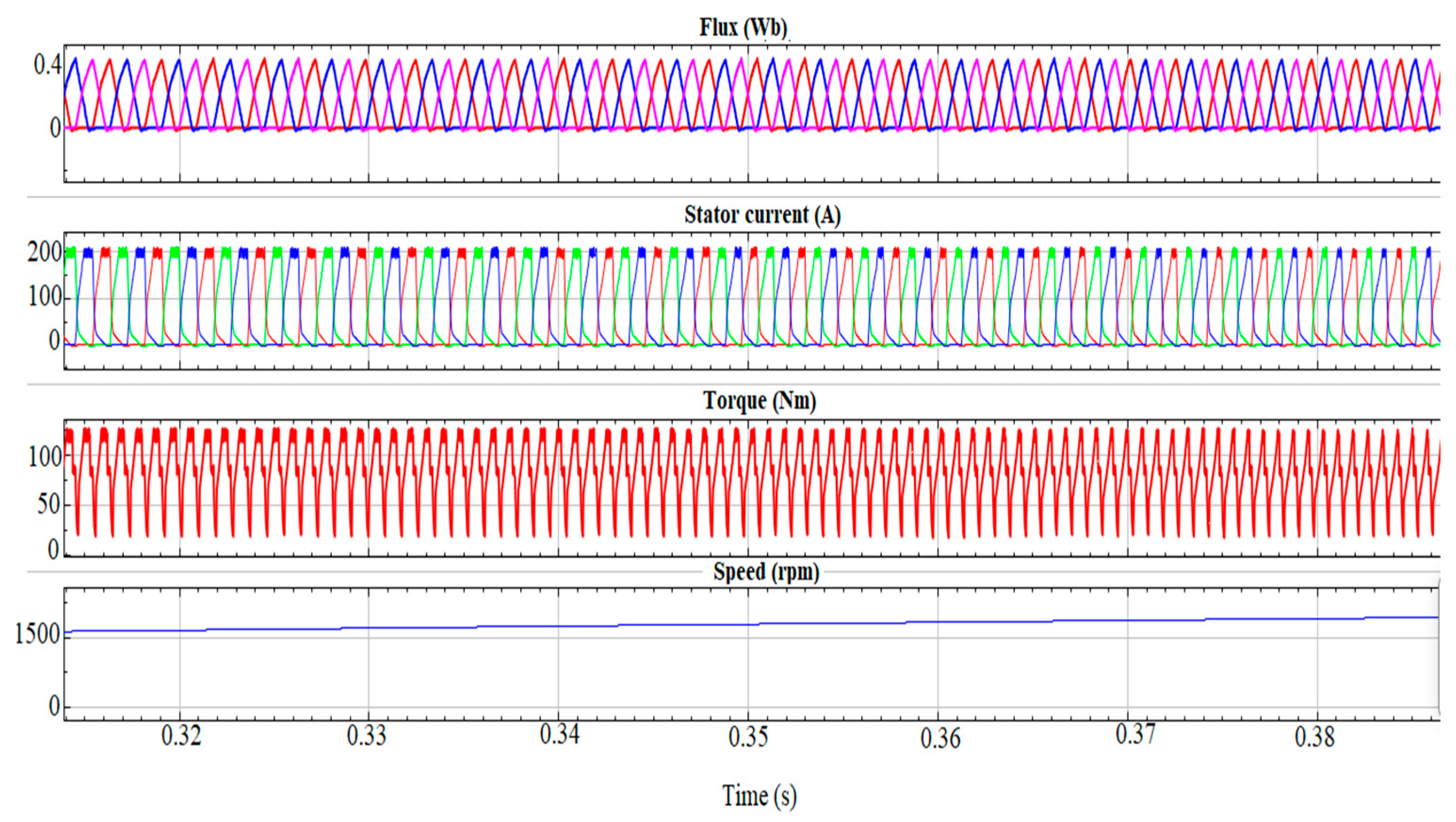
Figure 7.
Traction mode characteristics of SRM-based EV (MPC).
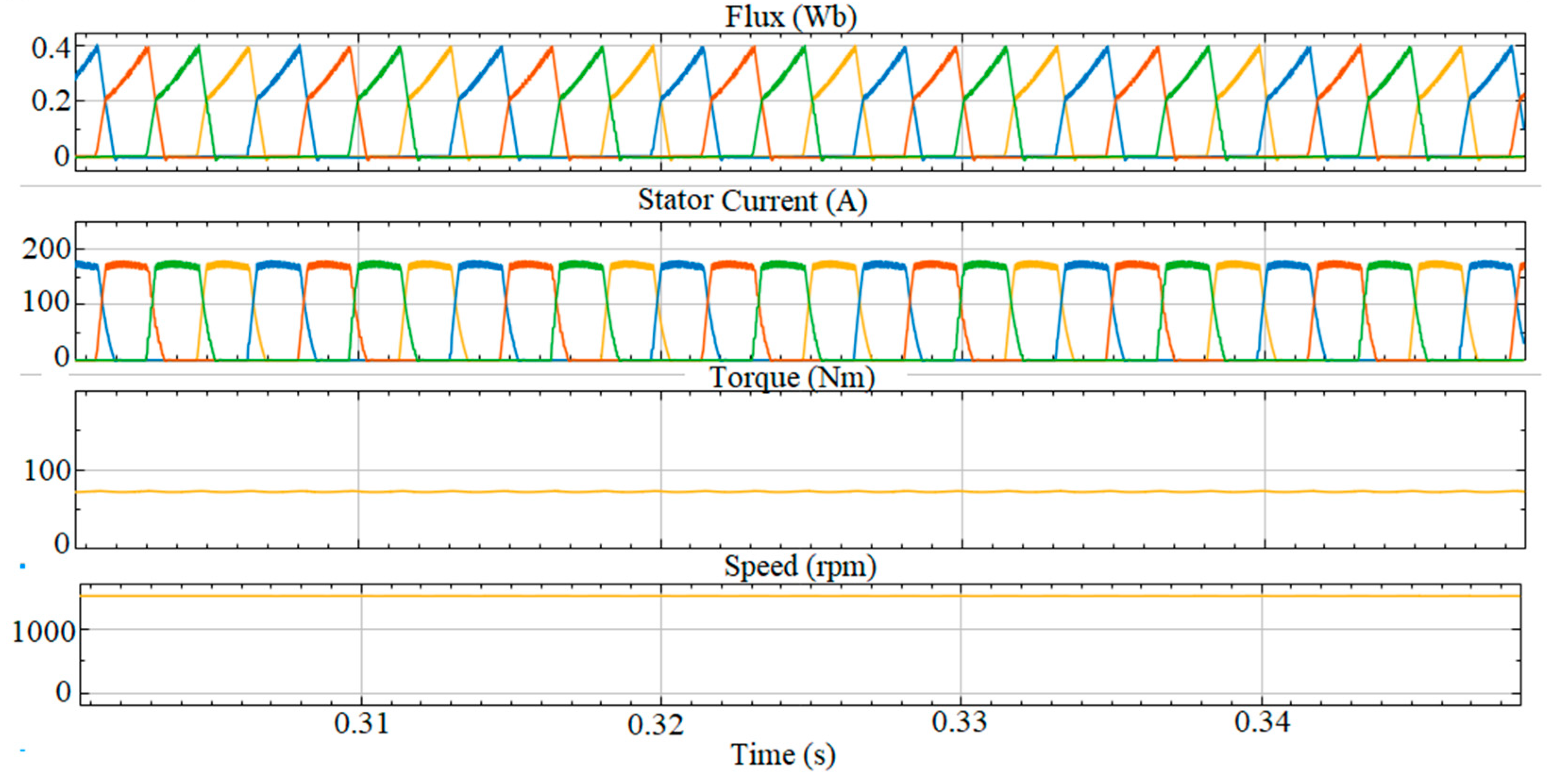
Figure 8.
Traction mode characteristics of SRM-based EV (SMC).
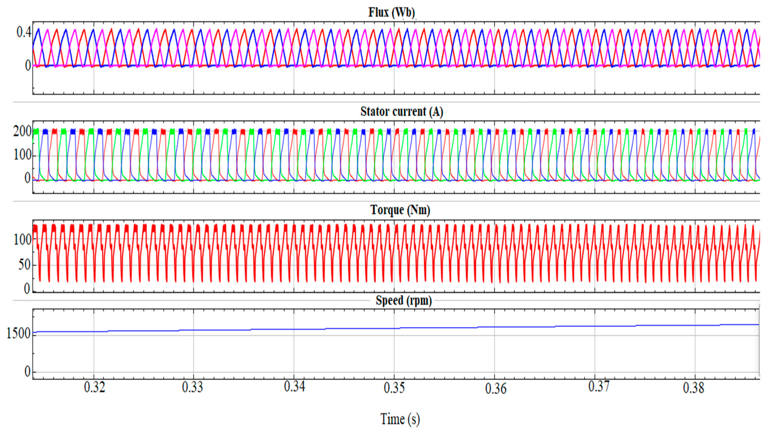
Torque ripple was found to be of magnitude 1.31 with hysteresis-based PI control, 0.0168 with MPC and 0.02 with SMC. To ensure a fair comparison of the three controllers, a comparative performance assessment was conducted over a common simulation interval of 0–30 s, corresponding to the initial portion of the Indian Drive Cycle (IDC). Each controller was subjected to identical drive cycle, motor, converter, and load conditions, and its performance was evaluated in terms of speed tracking, dynamic response, torque ripple, and current regulation parameters.
During the initial standstill and acceleration phase (Figure 9), the PI-based hysteresis controller exhibits significant deviation from the reference speed, particularly at low speeds, indicating limited robustness to parameter variations and load disturbances. The predictive MPC approach (Figure 10) shows a deviation from the reference speed as observed during the initial state. SMC demonstrates superior reference-speed tracking (Figure 11) during the acceleration and deceleration phases, with negligible steady-state error, reduced overshoot, and faster convergence to the commanded speed, compared with the PI-based hysteresis controller and MPC. The SMC law effectively compensates for parameter uncertainties and external disturbances, enabling rapid correction of speed deviations and improved robustness over the entire drive cycle. In contrast, although MPC is capable of following the reference speed, its response exhibits a finite tracking latency, accompanied by small overshoots and undershoots during rapid speed transitions. This behavior arises because MPC solves an online optimization problem at every sampling instant. For the SRM, which possesses small electrical time constants and requires high switching frequencies, the available computation time is limited, complicating the optimizer’s control action within each sampling interval, resulting in a tracking lag.
Figure 9.
Speed characteristics (PI control).
Figure 10.
Speed characteristics (MPC).
Figure 11.
Speed characteristics (SMC).
Analyzing the speed response for the controllers in Figure 12, SMC has a rise time of 14 s with minimal overshoot and negligible steady-state error. MPC does not match the fast convergence and accuracy of SMC. PI control takes more time to rise and settles at the base speed with a non-zero steady-state error. As inferred from Table 6, SMC has superior transient performance in terms of its faster rise and settling times and better accuracy during dynamic operation in EVs.
Figure 12.
Speed response: comparison of controllers.
Table 6.
Performance specifications of speed response: comparison of controllers (reference speed: 1500 rpm).
This improvement can be attributed to the inherent robustness of SMC against parameter uncertainties and external disturbances, enabling the controller to rapidly drive the system states onto the predefined sliding surface. In contrast, the conventional PI controller exhibits slower convergence and steady-state error, restrained by its limited capability to compensate for nonlinear system dynamics, under varying operating conditions. Although MPC provides improved transient behavior over PI control by optimizing the control action over a prediction horizon, its performance is constrained by model accuracy and computational overheads, leading to slower convergence than SMC. These characteristics indicate that SMC offers superior tracking capability and disturbance rejection, making it suitable for EV traction that demands rapid torque response, speed regulation, and robustness under varying load and driving conditions.
Figure 13 illustrates the electromagnetic torque response of the SRM under IDC using the PI-based hysteresis controller. The developed torque exhibits frequent high-amplitude oscillations because the fixed hysteresis band causes repetitive switching of the phase current. Consequently, rapid variations in torque are produced during acceleration and deceleration, which cause mechanical vibration, acoustic noise, and stress on the drivetrain, making this control strategy less suitable for demanding EV traction applications. Compared with PI-based hysteresis control, MPC in Figure 14 achieves improved current regulation by predicting future system behavior and optimizing the switching action over a finite prediction horizon. Torque pulsations remain during rapid speed transitions, as prediction errors and the finite optimization horizon limit the controller’s ability to respond instantaneously to highly nonlinear SRM dynamics. Although the ripple magnitude is lower than that of PI control, the torque waveform remains more oscillatory than that obtained using SMC in Figure 15. The torque waveform remains smooth throughout the drive cycle, even during rapid acceleration and deceleration events. The sliding-mode control law effectively compensates for parameter variations and external disturbances, maintaining the system on the sliding surface and producing phase current regulation. As a result, torque ripple is substantially reduced, leading to smoother power delivery, lower mechanical stress, and improved driving comfort.
Figure 13.
Torque characteristics: testing with drive cycle (PI-based hysteresis control).
Figure 14.
Torque characteristics: testing with drive cycle (MPC).
Figure 15.
Torque characteristics: testing with drive cycle (SMC).
This distinction is further clarified in Figure 16, Figure 17 and Figure 18 (zoomed version of Figure 13, Figure 14 and Figure 15 in the time interval [23.1–23.7 s]). SMC produces a smooth torque response, whereas PI control results in pronounced torque ripples. The torque characteristics for MPC have a bigger ripple envelope and more noticeable pulsations during drive cycle variations. The better performance of SMC is due to its robust control law, which stabilizes phase excitation more efficiently than the bang-bang style switching of PI control. These findings demonstrate that SMC produces a smoother and more steady torque characteristic with lower ripple compared to PI-based hysteresis control. This enhances the drivability and minimizes the mechanical stress for EVs, where comfort and component longevity are important.
Figure 16.
Torque characteristics: zoomed view (PI-based hysteresis control).
Figure 17.
Torque characteristics: zoomed view (MPC).
Figure 18.
Torque characteristics: zoomed view (SMC).
As inferred from Figure 19, the torque variations are more pronounced in PI-based hysteresis control compared to SMC. At t = 0.30 s, the reference speed was increased from 1500 rpm to 2500 rpm. The SMC controller (Figure 20) responds rapidly by adjusting the reference phase currents, ensuring stable torque output despite the abrupt change. Throughout the simulation process, the SMC scheme manages the rapid dynamics of switching to limit torque ripple to a narrow band, facilitating a quick response despite load changes. Unlike hysteresis control, torque ripple is not dictated by a fixed band but is significantly reduced by the sliding surface dynamics, which provide smoother current transitions during load variations. As shown in Figure 19 and Figure 20, both controllers generated a higher electromagnetic torque to accelerate the rotor and overcome its inertia. The SMC controller exhibited a faster recovery to the desired operating condition, with reduced torque oscillations and minimal speed overshoot compared with the PI controller. Following the transient, the torque rapidly returns to a stable value while the motor speed closely tracks the new reference, demonstrating the superior dynamic performance and robustness of the SMC strategy under sudden speed changes.
Figure 19.
Dynamic response of SRM-based EV drive to torque and speed changes (PI-based hysteresis control).
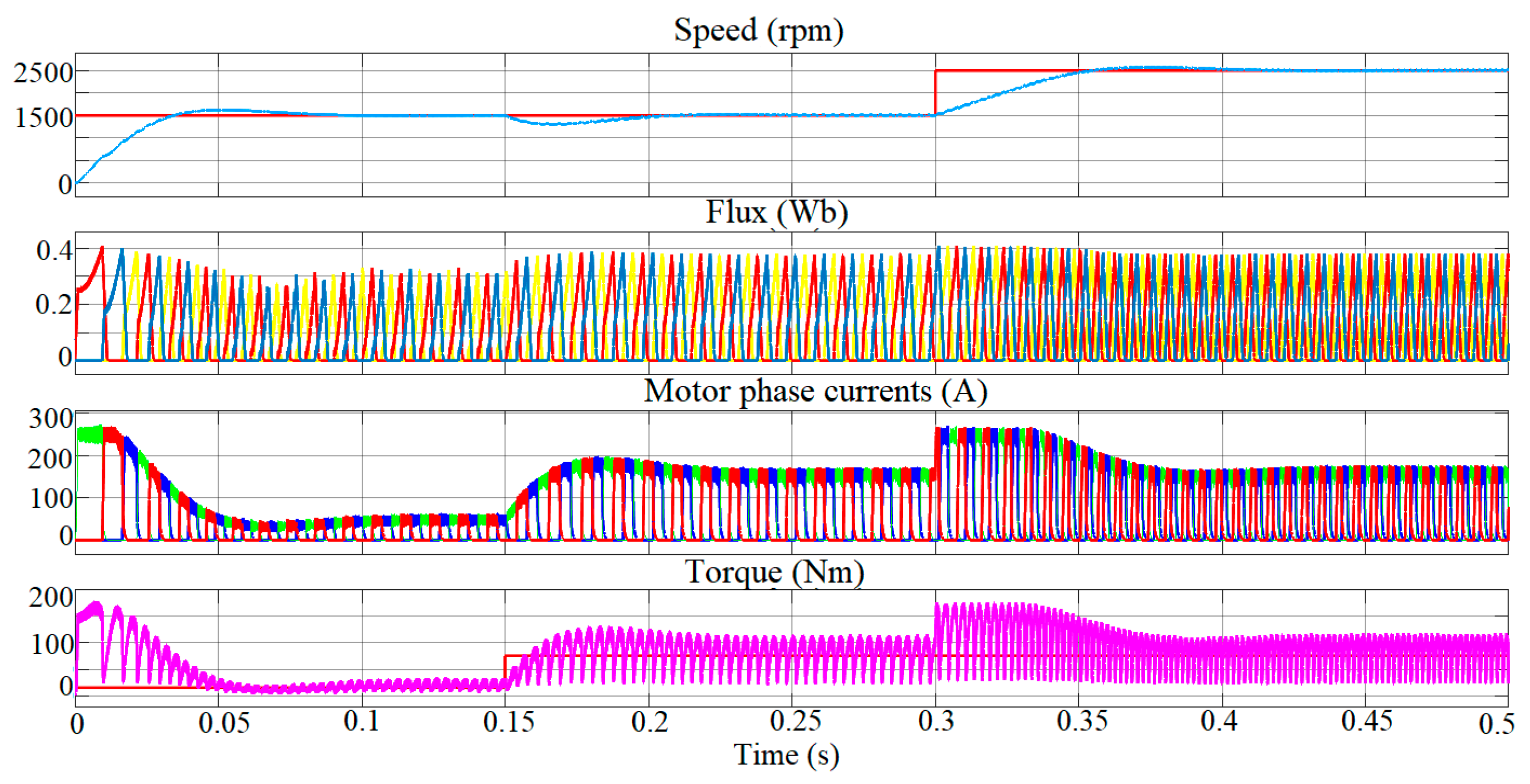
Figure 20.
Dynamic response of SRM-based EV drive to torque and speed changes (SMC).
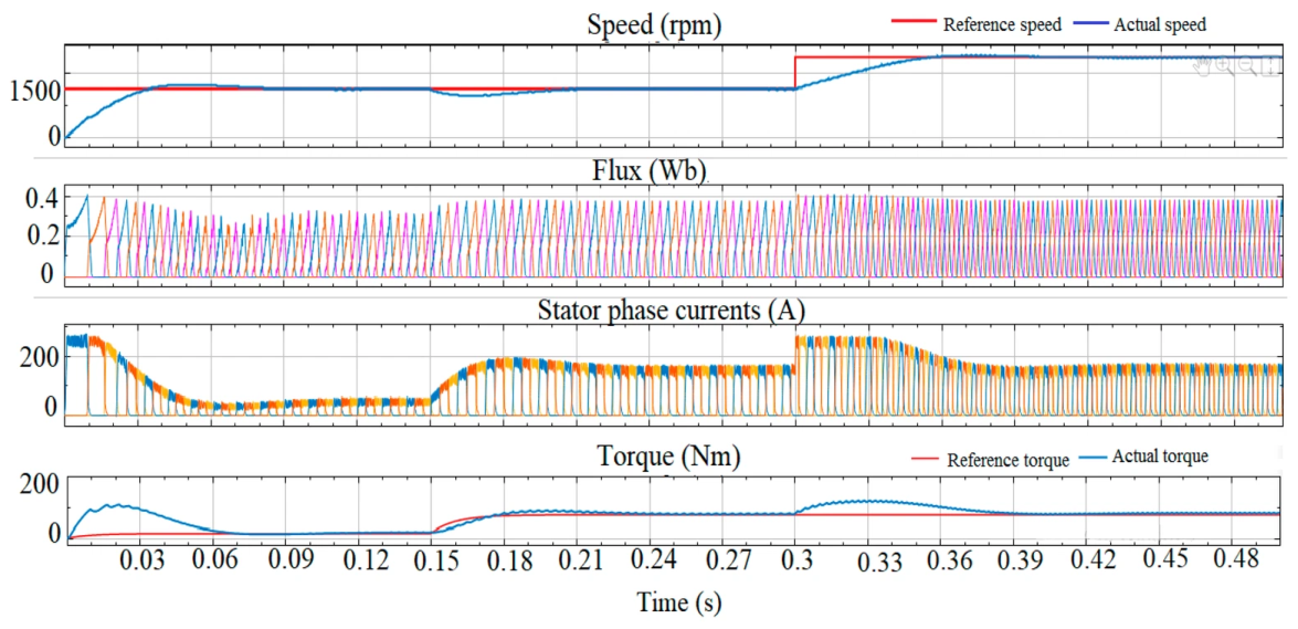
During the deceleration interval around 0.5 s in Figure 21, the SRM operates as a generator. The electromagnetic torque shifts toward negative values, signifying the machine’s opposition to the rotor motion, enabling energy recovery into the DC link. The flux also decays from larger motoring values and settles into smaller oscillations, implying lower current excitation in generating mode. The currents initially collapse from their motoring values and settle into low-magnitude oscillatory currents, similar to generator operation at light load. The rotor speed smoothly decelerates and tracks the new reference without oscillation or abrupt changes, demonstrating effective braking torque regulation.
Figure 21.
Traction mode characteristics of SRM-based EV during regenerative operation.
The present comparison is envisioned to provide a comparative performance of the three control strategies under common simulation settings rather than to deliver an exhaustive analysis of their specific design approaches. A thorough comparison comprising systematic controller tuning techniques, computational difficulty, execution time, sensitivity to parameter changes, and implementation-specific reflections is beyond the scope of the present work and is intended as a separate analysis. The present study focuses on the dynamic response and torque ripple profile under the specified common operating conditions.
Unlike the PI-based hysteresis and SMC controllers, the MPC controller necessitates the motor state to be predicted over the selected finite horizon and an optimization problem to be evaluated at each controller update. Hence, MPC involves a larger algorithmic computational burden associated with prediction and optimization. The present work does not experimentally estimate the execution time per control step or processor utilization of MPC on the target DSP. Hence, no numerical processor load or execution time value is presented in this research.
The performance of the PI-based hysteresis controller, MPC, and SMC is influenced by changes in SRM parameters due to temperature, magnetic saturation, rotor position, and loading conditions, as depicted in Table 7. As no parameter sensitivity work was performed, the comparison provides the major sensitivity mechanisms rather than quantitative robustness margins.
Table 7.
Qualitative assessment of PI, MPC, and SMC under SRM parameter variations.
Parameter variations predominantly affect the current dynamics and gain-dependent response of the PI-based hysteresis controller, while MPC is directly affected as its prediction depends on the motor model. SMC can compensate for bounded uncertainties and disturbances based on the chosen controller gains and uncertainty range. For the present work, all three controllers were assessed assuming nominal SRM parameters. Hence, the controller comparison considers only the specified nominal operating states.
Recent studies have used online parameter modification to compensate for motor–model mismatch in predictive control, while another study has proposed online identification of temperature-dependent electrical parameters. These studies prove that online parameter approximation and model updating can advance predictive control accuracy and robustness under different operating environments. This accounts for parameters such as temperature-dependent resistance, nonlinear inductance, magnetic saturation, and operating point variations [39,40].
4.3. Grid-Connected Mode
The G2V/V2G operating mode is activated by a mode selection command generated by the vehicle control unit. After successful grid synchronization and confirmation that the reconfiguration relays (RA, RB, and RC) are switched to position 2 and the grid interface relay G is closed, as shown in Figure 5, the converter operates in either G2V or V2G mode, according to the selected operating command.
In G2V mode, the EV operates as a grid-synchronized controllable load, where phase-locked loop (PLL)-based synchronization and dq-axis PI current regulation enable unity power factor charging through active power control (id*) while maintaining iq* ≈ 0. In V2G mode, the IBC operates as a grid-connected inverter, providing sinusoidal current pursuant to power references (P*, Q*) that are transformed into dq-current commands (id*, iq*) for ancillary services like voltage/frequency regulation and peak shaving.
Figure 22 shows the constant battery voltage, implying controlled discharge dependent on the dq controller current. This reduces voltage drops and restricts deep discharge cycles, which enhance battery service life. The gradual decline in the SoC reflects stable energy injection into the grid over the operating period. In Figure 23, voltage and current waveforms are sinusoidal, in phase with negligible phase shift. The high power factor, inferred from the in-phase voltage and currents, indicates that the converter supplies real power with minimal harmonic injection. The estimated current THD is 4.79% in Figure 24, signifying low current distortion under the tested V2G simulation settings [41,42].
Figure 22.
Battery characteristics during V2G mode: SoC, voltage and current.
Figure 23.
Grid voltage and injected current during V2G mode.
Figure 24.
Total harmonic distortion (THD) of injected grid current during V2G mode.
In G2V mode, the IBC charges the battery from the grid. The battery voltage remains stable and the SoC waveform shows a smooth rise over time, as shown in Figure 25, indicating that the controller regulates a stable charging process. The G2V mode’s power factor reflects the efficiency with which the vehicle extracts grid power from the grid. In Figure 26, the grid injected current waveform is out of phase with the voltage, though they have the same zero-crossing alignment. This indicates a power factor above 0.9, which is ideal in utility-scale power systems. The THD calculated was 3.3%, as shown in Figure 27, showing low harmonic distortions coupled into the grid under the tested G2V operating condition.
Figure 25.
Battery characteristics during G2V mode: SoC, voltage and current.
Figure 26.
Grid voltage and injected current during G2V mode.
Figure 27.
Total harmonic distortion (THD) of injected grid current.
5. Prototype Implementation
The experimental prototype is implemented using a reconfigurable IBC with a 12/8 SRM and is controlled by a Texas Instruments(Dallas, TX, USA) TMS320F28379D real-time microcontroller (200 MHz dual-core C28x architecture) [43], which executes the proposed control algorithm and generates the converter switching signals, as illustrated in Figure 28.
Figure 28.
The proposed IBC prototype board.
The transition between traction, G2V, and V2G modes is achieved using a firmware-controlled relay sequence on the TMS320F28379D controller. In Fig. 28, A, B, and C denote the three-phase AC supply terminals, N denotes the neutral terminal, and A1–A2, B1–B2, and C1–C2 denote the corresponding SRM phase-winding terminals.The relay commands are generated through GPIO outputs, while relay position feedback is supervised to verify the commanded configuration. During mode alteration, the PWM outputs are deactivated to halt the active power conversion. The equivalent SRM phase path is isolated before the relay configuration is altered. A programmed isolation interval of 100 ms is introduced to enable the current to decay and the relay contacts to settle. After this interval, the relay feedback signals are checked against the commanded mode. The new operating-mode control algorithm is activated only after the relay configuration is confirmed. Hence, active power conversion is prevented during the relay transition, averting simultaneous overlap of the traction and grid-side control paths. The firmware constantly monitors relay-state feedback; an undefined or mismatched relay state disables the PWM outputs and the system enters a safe state.
The 100 ms interval signifies the programmed firmware isolation/dead-time and should not be deduced as the mechanical relay switching time or as the measured settling time of the converter. The current experimental setup did not involve high-bandwidth measurements for quantifying the transient DC-link voltage changes, phase current and grid current deviations or complete transition settling time. The reconfiguration sequence also avoids intentional hot switching of the relay contacts.
It should be highlighted that the quantitative controller performance assessment was performed with a three-phase 6/4 SRM simulation model, whereas the experimental prototype was developed with a three-phase 12/8 SRM prototype. Direct quantitative comparison of torque ripple and controller dynamics between the two platforms is beyond the scope of this research.
The simulation model utilized a three-phase 6/4 SRM while the laboratory prototype used a three-phase 12/8 SRM, as an apt 6/4 SRM with the essential experimental rating was not accessible for prototype testing. This does not alter the important reconfiguration principle of the proposed IBC, as the IBC employs the same three-phase asymmetric half-bridge configuration and relay-based arrangement to aid traction, G2V, and V2G modes. The electromagnetic profiles of the two machines are inherently different. The inductance and flux linkage characteristics, commutation profiles, torque generation, torque ripple, and dynamic current response rely on SRM pole configuration and machine parameters. The simulation establishes the operation and control performance of the proposed IBC, while the experimental results validate the practical feasibility of realizing the reconfigurable IBC with the 12/8 SRM prototype.
Figure 29 presents the complete experimental test bench, where the hardware prototype is integrated with the SRM and loading arrangement, battery source, isolation transformer, and grid connection for validating the proposed control strategy under practical operating conditions. The experimental results establish the practical implementation of the proposed drive and its functioning in traction, G2V, and V2G modes. As the simulation and experimental stages utilize varying SRM configurations and ratings, the results obtained are considered complementary rather than directly comparable. Table 8 presents the salient prototype rating and parameters. For each operating mode, the corresponding control algorithm was implemented on the TMS320F28379D controller, and electrical quantities such as phase currents, DC-link voltage, battery current, grid voltage, and grid current were measured using a digital oscilloscope and current probes.
Figure 29.
Experimental testing of the proposed SRM drive.
Table 8.
Experimental prototype parameters.
5.1. Traction Mode
The SRM drive was experimentally evaluated in traction mode under different mechanical loading conditions to emulate EV operating scenarios, including light-load cruising, acceleration, and hill-climbing. Mechanical loading was applied using a calibrated brake drum and spring balance arrangement to produce controlled torque levels. The motor speed was varied through the reference potentiometer interfaced with the controller, thereby emulating the accelerator pedal of an EV.
The PWM pulses in Figure 30 demonstrate complimentary gate switching with dead-time addition, which validates the control logic and signal isolation. The battery voltage is steady during phase commutation, with minimum ripple injection. The battery current shows how the SRM phases are excited and demagnetized sequentially one after the other, with the rising edge depicting the phase turn ON, as illustrated in Figure 31. The torque–speed profile in Figure 32 indicates that the developed torque decreases with increasing motor speed. At approximately 1295 rpm, a torque of about 4.5 N·m is obtained. The corresponding mechanical output power is approximately 0.61 kW, as shown in Figure 33. The battery power output increases with load and attains its peak value during mid-range speed. The battery current increases from 4.6 A to 20 A as torque demand increases, while the voltage drop remains minimal.
Figure 30.
CH1 (yellow)—PWM_1A @50% duty cycle, CH2 (cyan)—PWM_1B @50% duty cycle.
Figure 31.
CH1 (yellow)—battery voltage, CH2 (cyan)—battery current.
Figure 32.
Torque speed profile for SRM drive.
Figure 33.
Power–speed profile for SRM drive.
The SoC was estimated from the measured terminal voltage utilizing the fully charged voltage of 54 V and deep-discharge cutoff voltage of 37 V to state the permitted operating region of G2V and V2G modes. During G2V, charging is stopped at an upper SoC threshold of 90%, while V2G is permitted above 40% SoC and stopped at 20% SoC to prevent excessive discharge and related battery degradation. The current reference during the grid-interfacing mode is scaled based on the battery SoC to sustain the recommended operating limits.
5.2. Grid-Connected Mode Testing
By adjusting the pulse width modulated ratio of the IBC, the PI loop regulates the charging/discharging current and therefore the power delivered/absorbed from the grid using the potentiometer in G2V/V2G mode. For practical grid-connected mode, auxiliary interface and filtering elements are used to facilitate safe and stable operation of the experimental platform. These comprise the grid-side filtering/isolation configuration and the DC-link voltage stabilization capacitor. These are associated with the practical grid interface and experimental implementation rather than with the reconfiguration mechanism of the proposed IBC. In the Grid-Tied Inverter (GTI) approach, dq control is applied for harmonic suppression, PFC and precise synchronization with grid voltage and frequency. The negative Id reference indicates that the grid is transferring active power into the DC link for battery charging.
The results recorded with a 5 A Current Transformer (CT) and a 100 Ω load resistor show a sinusoidal profile, as presented in Figure 34. CH1 (yellow) shows the PLL-generated electrical angle (ωt) ramp synchronized with the utility grid. The ramp varies linearly from 0 to 2π severe grid cycle and provides the common phase reference for converter control. During G2V operation, the synchronized angle is used to generate an in-phase current reference, enabling unity power factor charging. During V2G operation, the current reference polarity is reversed, allowing for controlled power injection into the grid without losing synchronization. Channel 1 (ωt ramp) displayed a smooth, linearly increasing waveform, which confirms that the PLL remained locked to the grid frequency and phase. The current closely follows the sinusoidal grid voltage waveform corresponding to a charging current of about 1.9 A. The charging profile shown in Figure 35 displays steady voltage without ripple or drop.
Figure 34.
CH1 (yellow)—wt ramp signal, CH2 (cyan)—battery charging current, CH3(purple)—grid current using 5A CT with 100 ohm loading resistor, CH4 (blue)—grid voltage.
Figure 35.
CH1 (yellow)—battery voltage, CH2 (cyan)—charging currentduring G2V mode.
During testing, the power factor measured by a Fluke power analyzer 1770 series [43] was −0.90, as shown in Figure 36. The negative sign signifies a leading (capacitive) power factor, arising from the reactive power support provided by the dq-based grid current control. The grid-side current THD was recorded at 3.3% (Figure 37), with no dominant lower-order harmonics (3rd or 5th), confirming low distortion.
Figure 36.
Power factor recorded with Fluke meter during G2V.
Figure 37.
Current harmonics recorded with a Fluke meter during G2V.
Upon receiving a V2G mode command from the supervisory controller, the DSP reconfigures the operation of the IBC through software by changing the switching sequence and control algorithm. Consequently, the IBC operates as a GTI employing synchronous dq-axis current control together with the PLL to synchronize its output voltage phase and frequency with the utility grid. A positive Id reference commands active power injection from the battery pack to the utility grid, while the Iq reference is maintained at zero to ensure near-unity power factor operation.
The ωt signal (Figure 38) displays the instantaneous electrical angle of the grid voltage monitored by the PLL. This ramp signal is utilized to convert the abc-frame voltages/currents to the synchronous dq frame for simpler regulation of active (Id) and reactive (Iq) current components. The battery is discharging, as seen in Figure 39, yet the battery voltage stays constant, signifying little ripple. Despite the discharge current, the battery terminal voltage remains nearly constant at approximately 49.7 V, exhibiting only a small peak-to-peak ripple of about 0.6 V (≈1.2% of the nominal voltage).
Figure 38.
CH1 (yellow)—wt ramp signal, CH2 (cyan)—Id reference at 1.3 A, CH3 (purple)—inverter current from current sensor, CH4 (blue)—inverter voltage.
Figure 39.
CH1 (yellow)—battery voltage, CH2 (cyan)—charging current.
The power factor computed using the Fluke meter [44] during V2G operation was 0.90 while the current THD was around 5.2%, as shown in Figure 40 and Figure 41. The THD and PF results indicate that the proposed IBC provides relatively low current distortion under the tested V2G and G2V operating condition. However, THD alone is not adequate to establish compliance with IEEE 519 or IEC 61000-3-2 [41], as such compliance needs consideration of the harmonic limits, individual harmonic components, and relevant measurement and system conditions. Hence, the estimated THD and power factor reported here are experimental power quality values rather than a formal declaration of standards compliance.
Figure 40.
Power factor recorded with Fluke meter during V2G function.
Figure 41.
Current harmonics recorded with a Fluke meter during V2G function.
6. Discussion
The simulation and experimental work were performed with separate SRM configurations and voltage levels due to practical constraints. The experimental grid interface includes the essential voltage transformation and isolation arrangement for safe low-voltage prototype testing. Hence, the absolute electromagnetic parameters measured from the two systems are not identical, as SRM torque, flux linkage, inductance, current profile and torque ripple rely on the machine pole configuration and its electrical parameters.
The simulation results establish the operating principle and control performance of the proposed IBC under the stated simulation conditions. The experimental results are presented to illustrate the practical realization of the topology and its traction, G2V, and V2G functioning modes. The ensuing assessment is limited to theoretically meaningful parameters, like operating mode functionality, bidirectional power transfer, power factor, grid current THD, and controller realization.
The simulation study validates the proposed reconfigurable SRM-based integrated bidirectional converter under traction, G2V, and V2G operating modes. The primary aim of the present work is fast speed tracking with minimized torque ripple. Though MPC had a slightly lower torque ripple coefficient of 0.0168, SMC was chosen as an apt compromise between dynamic speed response, torque ripple reduction, and implementation complexity for the objectives of the present study. This should not be inferred as a claim of universal superiority of SMC over MPC or PI control. Compared with PI-based hysteresis control and MPC, SMC exhibits faster speed tracking, lower steady-state error, improved disturbance rejection, and significantly reduced torque ripple during both steady-state and transient operating conditions.
Overall, the simulation results confirm that the proposed converter satisfies the principal objectives of this work:
- Realization of a reconfigurable converter capable of traction, G2V and V2G operation using the same hardware;
- A reduction in additional passive components through SRM winding reuse;
- Improved traction performance using SMC;
- Bidirectional power exchange with a high power factor and low current harmonic distortion under the tested operating conditions.
The experimental investigation confirmed the practical implementation of the proposed SRM-based integrated bidirectional converter, as depicted in Table 9. Successful reconfiguration between traction, G2V, and V2G modes was established with the relay-assisted control arrangement. The PLL maintains accurate synchronization with the utility grid, enabling controlled bidirectional power flow. The measured battery voltage exhibits only small ripple during both charging and discharging, while the injected grid current remains sinusoidal and synchronized with the grid voltage.
Table 9.
Summary of experimental performance in traction, G2Vand V2G modes.
A direct one-to-one comparison between simulation and hardware results is not possible in the present work due to variations in system ratings, component specifications, and implementation constraints. Certain elements in simulation—such as ideal switches, precise inductance profiles, and lossless interconnections—cannot be replicated in hardware. In certain cases, equivalent or substitute components had to be used in hardware due to availability constraints.
The present experimental setup assesses the steady-state performance of the traction, G2V, and V2G operating modes. Though the relay-based reconfiguration sequence introduces an isolation interval to avert concurrent conduction during mode changes, separate high-speed categorization of the transition transients was not undertaken in this study. Future work will therefore investigate the traction–G2V–V2G transitions utilizing synchronized high-bandwidth measurements of the DC-link voltage, SRM phase currents, and grid currents.
Although the proposed converter demonstrates satisfactory performance under laboratory conditions, several practical aspects remain beyond the scope of the present work. The prototype is limited to a 1 kW rating, and only normal grid conditions are considered. Battery ageing, converter thermal behavior, islanding detection, and operation under grid disturbances have not been experimentally investigated. These aspects require further study before large-scale deployment. Future work will focus on scaling the converter to higher power levels suitable for commercial EVs, integrating renewable energy sources and vehicle-to-home operation, implementing adaptive battery management based on state-of-health estimation, incorporating fault-tolerant converter operation, and validating the system under weak-grid and grid-fault conditions. Further research advancements in this domain can contribute to a greener, energy efficient and low carbon emission future.
A quantitative real-time computational comparative analysis necessitates deployment of all controllers on the same processor with identical sampling and compiler settings, along with estimation of average and worst-case execution time and processor utilization. Such a study is considered part of future work. The experimental validation in this study validates the feasibility of the proposed SRM-based IBC utilizing a 1 kW laboratory prototype under normal operating settings. Further examinations incorporating higher power prototypes, thermal and efficiency characterization, automotive-grade components, reliability and fault tolerance analysis, battery ageing, electromagnetic compatibility, and operation under different grid conditions are essential to validate scalability and practical deployment potential.
A comprehensive experimentally validated loss decomposition, including temperature-dependent semiconductor losses, winding resistance, relay contact resistance, and filter inductor losses, is identified as an important extension of the present work.
Though the proposed IBC illustrates bidirectional grid-connected functionality in V2G mode, anti-islanding and protection event tests were not conducted in the present experimental investigation. Comprehensive grid-compliance testing entails analysis over different operating powers and grid conditions, involving changes in grid impedance, voltage disturbances, frequency deviations, and protection-related events owing to the restrictions of the laboratory grid interface. Future work will assess dedicated anti-islanding detection and protection techniques and analyze converter response under abnormal voltage, current, frequency, fault, and emergency disconnection settings.
7. Conclusions
This paper proposed a reconfigurable SRM-based IBC, operable in traction, G2V and V2G modes, while utilizing the existing SRM converter and motor windings for bidirectional power conversion and maintaining traction performance and grid power quality. In the simulation, SMC produced fast dynamic response, low torque ripple, and high-speed tracking, in tandem with dynamic load and drive cycle variations compared with other investigated controllers. The 12/8 SRM prototype experimentally demonstrated real-time mode switching and control using the TMS320F28379D microcontroller, validating the operational modes under the tested experimental conditions.
The proposed SRM-based IBC system supports the United Nations Sustainable Development Goals (SDGs)—SDG 7 (Affordable and Clean Energy) and SDG 9 (Industry, Innovation, and Infrastructure) via effective power conversion and diminished need for rare-earth metals, resulting in cost-effective EV drives. Furthermore, this work is aligned with SDG 11 (Sustainable Cities and Communities) and SDG 13 (Climate Action), by lowering greenhouse gas emissions and creating sustainable transportation systems. The proposed SRM-based IBC system does this by making energy use more efficient and making it easier for people to switch to EVs. Research and development in this domain can meaningfully contribute toward a cleaner, energy-efficient, and low-carbon future.
The future scope of research will focus on utilizing the proposed SRM-based IBC to meet the demands of V2G networks by combining renewable generation. This means developing the dq-based control for active and reactive power management, grid code adherence, and voltage/frequency regulation. The latter is expected to facilitate the deployment of SRM-based EV chargers as manageable grid assets and harness renewable energy, obviating supplementary power conversions. Although the prototype achieved the intended operating objectives, several practical observations warrant further investigation. During topology reconfiguration, brief transient oscillations associated with relay switching and converter dead-time was observed but did not affect stable operation. In addition, the present work validated the concept using a 1 kW laboratory prototype under normal grid conditions; therefore, the influence of higher power ratings, battery ageing, weak-grid operation, thermal behavior, and fault conditions was not investigated. These limitations indicate opportunities for further research aimed at improving robustness and scalability.
Author Contributions
Conceptualization, S.K. and J.R.-G.; methodology, S.K. and C.Á.-B.; software, S.K. and C.Á.-B.; validation, P.P.K.P.; investigation, J.R.-G.; data curation, S.K., P.P.K.P. and C.Á.-B.; writing—original draft, S.K.; writing—review and editing, J.R.-G.; visualization, S.K. and P.P.K.P.; supervision, P.P.K.P. and J.R.-G.; project administration, P.P.K.P. All authors have read and agreed to the published version of the manuscript.
Funding
This work was supported in part by the Universitat Politècnica de València under grant PAID-10-21. This study was also supported through an AMRITA Seed Grant (Proposal ID: ASG2022188).
Data Availability Statement
The original contributions presented in this study are included in the article. Further inquiries can be directed to the corresponding authors.
Acknowledgments
The authors gratefully acknowledge Sri Mata Amritanandamayi Devi (Amma), Chancellor, Amrita Vishwa Vidyapeetham, for her inspiration and for providing financial support for the Article Processing Charges (APCs) of this publication.
Conflicts of Interest
The authors declare no conflicts of interest.
Abbreviations
The following abbreviations are used in this manuscript:
| CC/CV | Constant current/constant voltage |
| CT | Current transformer |
| DQ | Direct quadrature |
| DSP | Digital signal processor |
| EV | Electric vehicle |
| G2V | Grid-to-vehicle |
| HEV | Hybrid electric vehicle |
| IBC | Integrated battery charger |
| ICE | Internal combustion engine |
| IM | Induction motor |
| MMC | Modular multilevel converter |
| MOSFT | Metal oxide semiconductor field-effect transistor |
| OBC | On-board charger |
| OBCS | On-board charging system |
| OFBCS | Off-board charging system |
| PFC | Power factor correction |
| PLL | Phase-locked loop |
| PMSM | Permanent magnet synchronous motor |
| PWM | Pulse width modulation |
| SoC | State of Charge |
| SPDT | Single-pole double-throw |
| SMC | Sliding-mode control |
| SRM | Switched reluctance motor |
| THD | Total harmonic distortion |
| VSI | Voltage source inverter |
| V2G | Vehicle-to-Grid |
References
- Rekhasree, R.L.; Sreelekshmi, R.S.; Nair, M.G. Power Quality Enhancement in Grid Connected Renewable Energy Microgrids with Energy Storage: A Comprehensive Review. IEEE Access 2026, 14, 33275–33290. [Google Scholar] [CrossRef] [Scilit]
- Sreeram, K.; Preetha, P.K.; Poornachandran, P. Electric Vehicle Scenario in India: RoadMap, Challenges and Opportunities. In Proceedings of the 2019 IEEE International Conference on Electrical, Computer and Communication Technologies (ICECCT), Coimbatore, India, 20–22 February 2019; pp. 1–7. [Google Scholar] [CrossRef] [Scilit]
- Krishna, N.G.; Sreelekshmi, R.S.; Nair, M.G. Comprehensive Review on the Developments in Battery/Supercapacitor-Based Hybrid Energy Storage System for Electric Vehicles. In Lecture Notes in Electrical Engineering; Spring: Berlin/Heidelberg, Germany, 2023; pp. 341–361. [Google Scholar] [CrossRef] [Scilit]
- Cai, S.; Kirtley, J.L.; Lee, C.H.T. Critical Review of Direct-Drive Electrical Machine Systems for Electric and Hybrid Electric Vehicles. IEEE Trans. Energy Convers. 2022, 37, 2657–2668. [Google Scholar] [CrossRef] [Scilit]
- Mohanraj, D.; Gopalakrishnan, J.; Chokkalingam, B.; Mihet-Popa, L. Critical Aspects of Electric Motor Drive Controllers and Mitigation of Torque Ripple—Review. IEEE Access 2022, 10, 73635–73674. [Google Scholar] [CrossRef] [Scilit]
- Sreeram, K.; Preetha, P.K. A Comprehensive Review of Different Electric Motors for Electric Vehicles Application. Int. J. Power Electron. Drive Syst. (IJPEDS) 2024, 15, 74–90. [Google Scholar] [CrossRef] [Scilit]
- Sreeram, K.; Preetha, P.K.; Rodríguez-García, J.; Álvarez-Bel, C. A Comprehensive Review of Torque and Speed Control Strategies for Switched Reluctance Motor Drives. CES Trans. Electr. Mach. Syst. 2025, 9, 46–75. [Google Scholar] [CrossRef] [Scilit]
- Payarou, T.; Pillay, P. Integrated Multipurpose Power Electronics Interface for Electric Vehicles. IEEE Trans. Transp. Electrif. 2023, 9, 2429–2443. [Google Scholar] [CrossRef] [Scilit]
- Zhou, K.; Fang, H.; Liu, Y. Driving–Charging Integrated Controller for Electric Vehicles. IEEE Access 2022, 10, 66545–66563. [Google Scholar] [CrossRef] [Scilit]
- Singh, A.K.; Pathak, M.K. A Comprehensive Review of Integrated Charger for on-Board Battery Charging Applications of Electric Vehicles. In Proceedings of the 2018 IEEE 8th Power India International Conference (PIICON), Kurukshetra, India, 10–12 December 2018; pp. 1–6. [Google Scholar] [CrossRef] [Scilit]
- Kido, Y.; Hoshi, N.; Chiba, A.; Ogasawara, S.; Takemoto, M. Novel switched reluctance motor drive circuit with voltage boost function without additional reactor. In Proceedings of the 2011 14th European Conference on Power Electronics and Applications, Birmingham, UK, 30 August–1 September 2011; pp. 1–10. [Google Scholar]
- Hu, Y.; Gan, C.; Cao, W.; Li, C.; Finney, S.J. Split Converter-Fed SRM Drive for Flexible Charging in EV/HEV Applications. IEEE Trans. Ind. Electron. 2015, 62, 6085–6095. [Google Scholar] [CrossRef] [Scilit]
- Chang, H.C.; Liaw, C.-M. An Integrated Driving/Charging Switched Reluctance Motor Drive Using Three-Phase Power Module. IEEE Trans. Ind. Electron. 2011, 58, 1763–1775. [Google Scholar] [CrossRef] [Scilit]
- Wu, T.; Li, W.; Ni, K.; Song, S.; Alkahtani, M. Modular Tri-Port Converter for Switched Reluctance Motor based Hybrid Electrical Vehicles. IEEE Access 2019, 7, 15989–15998. [Google Scholar] [CrossRef] [Scilit]
- Ma, M.; Chang, Z.; Hu, Y.; Li, F.; Gan, C.; Cao, W. An Integrated Switched Reluctance Motor Drive Topology with Voltage-Boosting and On-Board Charging Capabilities for Plug-In Hybrid Electric Vehicles (PHEVs). IEEE Access 2018, 6, 1550–1559. [Google Scholar] [CrossRef] [Scilit]
- Hu, Y.; Song, X.; Cao, W.; Ji, B. New SR Drive with Integrated Charging Capacity for Plug-In Hybrid Electric Vehicles (PHEVs). IEEE Trans. Ind. Electron. 2014, 61, 5722–5731. [Google Scholar] [CrossRef] [Scilit]
- Hu, Y.; Gan, C.; Sun, Q.; Li, P.; Wu, J.; Wen, H. Modular Tri-Port High-Power Converter for SRM Based Plug-in Hybrid Electrical Trucks. IEEE Trans. Power Electron. 2018, 33, 3247–3257. [Google Scholar] [CrossRef] [Scilit]
- Gan, C.; Wu, J.; Hu, Y.; Yang, S.; Cao, W.; Guerrero, J.M. New Integrated Multilevel Converter for Switched Reluctance Motor Drives in Plug-in Hybrid Electric Vehicles with Flexible Energy Conversion. IEEE Trans. Power Electron. 2017, 32, 3754–3766. [Google Scholar] [CrossRef] [Scilit]
- Gan, C.; Jin, N.; Sun, Q.; Kong, W.; Hu, Y.; Tolbert, L.M. Multiport Bidirectional SRM Drives for Solar-Assisted Hybrid Electric Bus Powertrain with Flexible Driving and Self-Charging Functions. IEEE Trans. Power Electron. 2018, 33, 8231–8245. [Google Scholar] [CrossRef] [Scilit]
- Cai, W.; Yi, F. An Integrated Multiport Power Converter with Small Capacitance Requirement for Switched Reluctance Motor Drive. IEEE Trans. Power Electron. 2016, 31, 3016–3026. [Google Scholar] [CrossRef] [Scilit]
- Hu, K.W.; Yi, P.H.; Liaw, C.M. An EV SRM Drive Powered by Battery/Supercapacitor with G2V and V2H/V2G Capabilities. IEEE Trans. Ind. Electron. 2015, 62, 4714–4727. [Google Scholar] [CrossRef] [Scilit]
- Gan, C.; Sun, Q.; Wu, J.; Kong, W.; Shi, C.; Hu, Y. MMC-Based SRM Drives with Decentralized Battery Energy Storage System for Hybrid Electric Vehicles. IEEE Trans. Power Electron. 2019, 34, 2608–2621. [Google Scholar] [CrossRef] [Scilit]
- Liang, J.; Jian, L.; Chang, M.; Xu, G. A compact integrated switched reluctance motor drive with bridgeless PFC converter. In Proceedings of the 2013 IEEE Energy Conversion Congress and Exposition, Denver, CO, USA, 15–19 September 2013; pp. 4719–4724. [Google Scholar]
- T, F.; Dominic, D.A.; Prajof, P. A Novel Single-Pulse Operated SRM Drive with Improved Performance and Integrated On-board Charging Capability for EVs. In Proceedings of the 2022 IEEE International Power and Renewable Energy Conference (IPRECON), Kollam, India, 21–23 November 2022; pp. 1–6. [Google Scholar]
- Thankachan, J.; Singh, S.P. A Reduced Switch Multiport Converter Drive for Solar-assisted SRM EV with Integrated Driving and Charging Features. In Proceedings of the 2020 IEEE International Conference on Power Electronics, Smart Grid and Renewable Energy (PESGRE2020), Cochin, India, 2–4 January 2020; pp. 1–6. [Google Scholar]
- Gujarathi, P.K.; Shah, V.; Lokhande, M. A seven switch all in one power electronic topology for converted plug-in hybrid electric vehicle. In Proceedings of the 2017 IEEE International Conference on Smart Technologies and Management for Computing, Communication, Controls, Energy and Materials (ICSTM), Chennai, India, 2–4 August 2017; pp. 477–483. [Google Scholar]
- Kumawat, G.; Shah, V.; Payami, S. A Universal-Input On-Board Charger Integrated Converter for SRM Drive Targeting Electric Vehicle Application. In Proceedings of the 2022 IEEE International Conference on Power Electronics, Drives and Energy Systems (PEDES), Jaipur, India, 14–17 December 2022; pp. 1–5. [Google Scholar]
- Deriszadeh, A.; Bojoi, R. An integrated battery-charger for switched reluctance motor drives. In Proceedings of the 2017 6th International Conference on Clean Electrical Power (ICCEP), Santa Margherita Ligure, Italy, 27–29 June 2017; pp. 446–451. [Google Scholar]
- Saeed, J.; Niakinezhad, M.; Wang, L.; Fetnando, N. An Integrated Charger with Hybrid Power Source Using PV Array for EV Application. In Proceedings of the 2019 IEEE 13th International Conference on Compatibility, Power Electronics and Power Engineering (CPE-POWERENG), Sonderborg, Denmark, 23–25 April 2019; pp. 1–6. [Google Scholar]
- Cheng, H.; Wang, L.; Xu, L.; Ge, X.; Yang, S. An Integrated Electrified Powertrain Topology with SRG and SRM for Plug-In Hybrid Electrical Vehicle. IEEE Trans. Ind. Electron. 2020, 67, 8231–8241. [Google Scholar] [CrossRef] [Scilit]
- Yi, F.; Cai, W. Modeling, Control, and Seamless Transition of the Bidirectional Battery-Driven Switched Reluctance Motor/Generator Drive Based on Integrated Multiport Power Converter for Electric Vehicle Applications. IEEE Trans. Power Electron. 2016, 31, 7099–7111. [Google Scholar] [CrossRef] [Scilit]
- Shah, V.; Payami, S. Fully Integrated Multilevel Power Converter for SRM Drive with Charging Capabilities (G2V) for Electric Vehicle Application. IEEE J. Emerg. Sel. Top. Ind. Electron. 2023, 4, 198–208. [Google Scholar] [CrossRef] [Scilit]
- Liang, J.; Xu, G.; Jian, L.; Chang, M. Analysis parking position of integrated switched reluctance motor drive system with on-board charger for EV. In Proceedings of the 2012 IEEE Vehicle Power and Propulsion Conference, Seoul, Republic of Korea, 9–12 October 2012; pp. 72–77. [Google Scholar]
- Chang, H.C.; Liaw, C.-M. A battery powered switched-reluctance motor drive established using three-phase power module. In Proceedings of the 2009 International Conference on Power Electronics and Drive Systems (PEDS), Taipei, Taiwan, 2–5 November 2009; pp. 643–648. [Google Scholar]
- Hu, Y.; Gan, C.; Hu, S.; Cao, W.; Wang, X.; Finney, S. Winding-centre-tapped switched reluctance motor drive for multi-source charging in electric vehicle applications. IET Power Electron. 2015, 8, 2067–2075, Erratum in IET Power Electron. 2016, 9, 1775. [Google Scholar] [CrossRef] [Scilit]
- Sun, Q.; Wu, J.; Gan, C.; Si, J.; Guo, J.; Hu, Y. Cascaded Multiport Converter for SRM-Based Hybrid Electrical Vehicle Applications. IEEE Trans. Power Electron. 2019, 34, 11940–11951. [Google Scholar] [CrossRef]
- Chang, H.C.; Liaw, C.M. On the Front-End Converter and Its Control for a Battery Powered Switched-Reluctance Motor Drive. IEEE Trans. Power Electron. 2008, 23, 2143–2156. [Google Scholar] [CrossRef] [Scilit]
- Hu, Y.; Gan, C.; Cao, W.; Fang, Y.; Finney, S.J.; Wu, J. Solar PV-Powered SRM Drive for EVs with Flexible Energy Control Functions. IEEE Trans. Ind. Appl. 2016, 52, 3357–3366. [Google Scholar] [CrossRef] [Scilit]
- Zhou, R.; Wang, H. Model Predictive Speed and Voltage Control of Sensorless PMSM with Parameter Rectification and A Reduced-Order EKF. IEEE Trans. Ind. Electron. [Google Scholar] [CrossRef] [Scilit]
- Yang, C.; Liu, W.; Song, B.; Chau, K.T. Signal-Injection-Free Online Identification of Temperature-Dependent Electrical Parameters for SPMSM Drives: An Alternating Dual-Adaline Approach. IEEE Trans. Transp. Electrif. [Google Scholar] [CrossRef] [Scilit]
- IEEE Std 519-2022; Standard for Harmonic Control in Electric Power Systems (Revision of IEEE Std 519-2014). IEEE Standards Association: Piscataway, NJ, USA, 2022. [Google Scholar] [CrossRef] [Scilit]
- Sakthivel, K.N.; Das, S.K.; Kini, K.R. Importance of quality AC power distribution and understanding of EMC standards IEC 61000-3-2, IEC 61000-3-3 and IEC 61000-3-11. In Proceedings of the 8th International Conference on Electromagnetic Interference and Compatibility, Chennai, India, 19–22 February 2003; pp. 423–430. [Google Scholar] [CrossRef] [Scilit]
- Texas Instruments. TMS320F2837xD Dual-Core Real-Time Microcontrollers Datasheet (Rev. P). Available online: https://www.ti.com/product/TMS320F28379D (accessed on 1 July 2026).
- Fluke. 1770 Series Three-Phase Power Quality Analyzers: 1773, 1775, 1777|Fluke. Fluke.com. 2025. Available online: https://www.fluke.com/en-us/product/electrical-testing/power-quality/1773-1775-1777 (accessed on 31 August 2026).
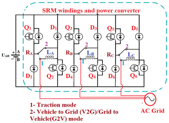
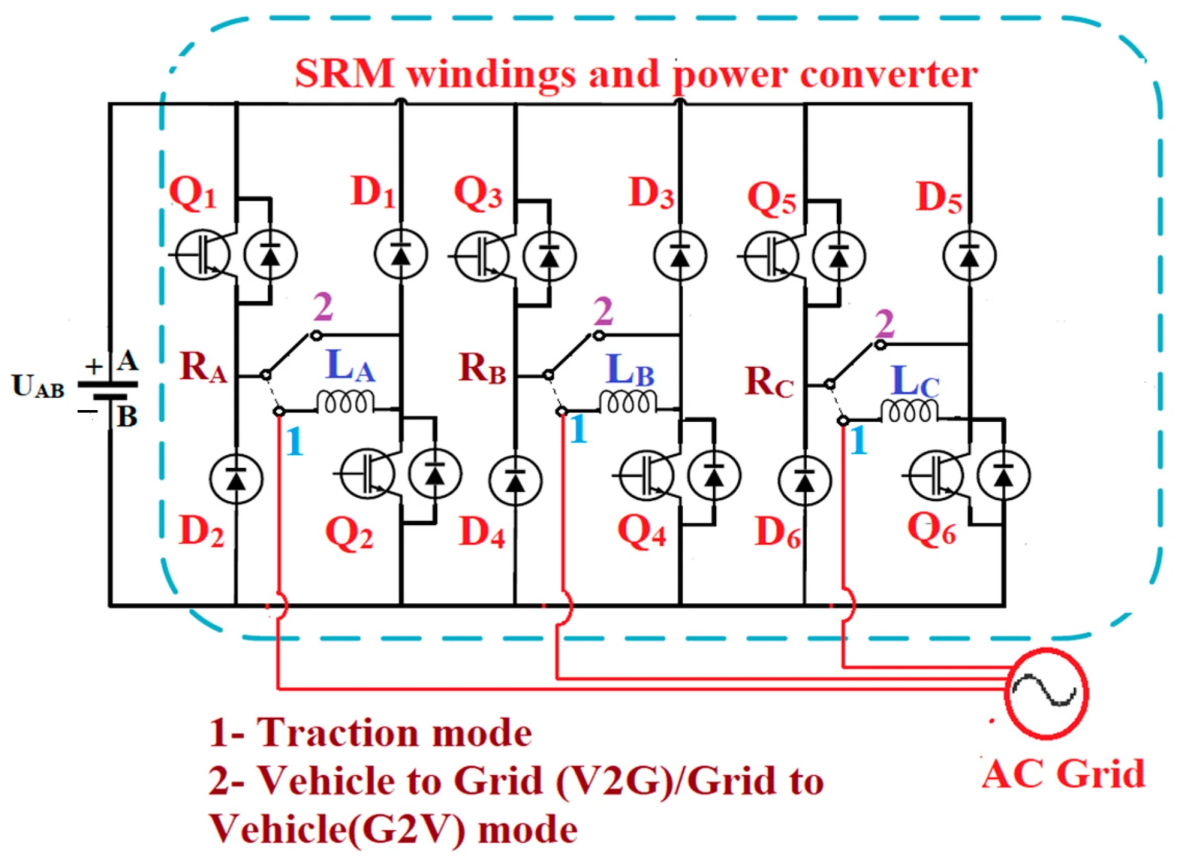
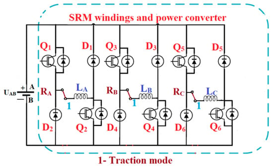
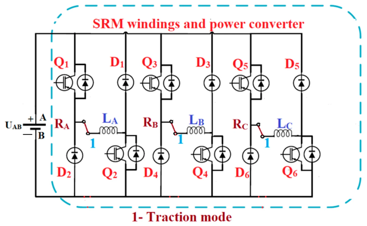
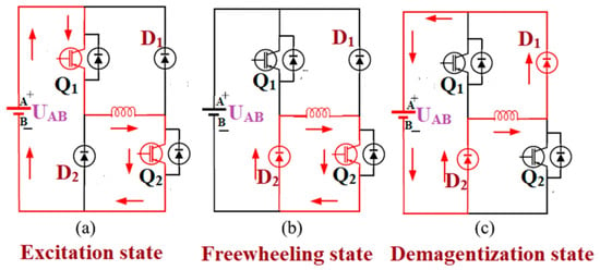
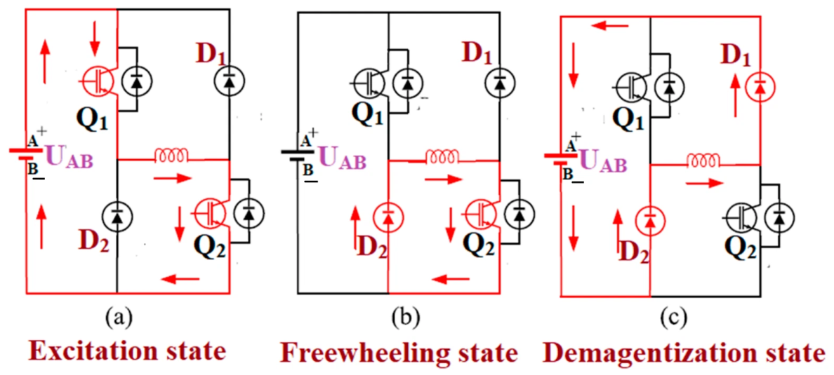
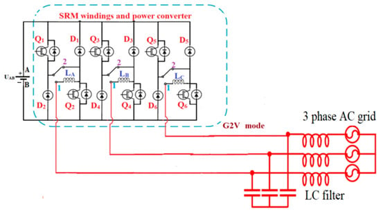
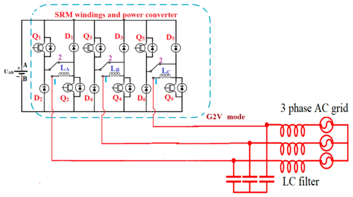
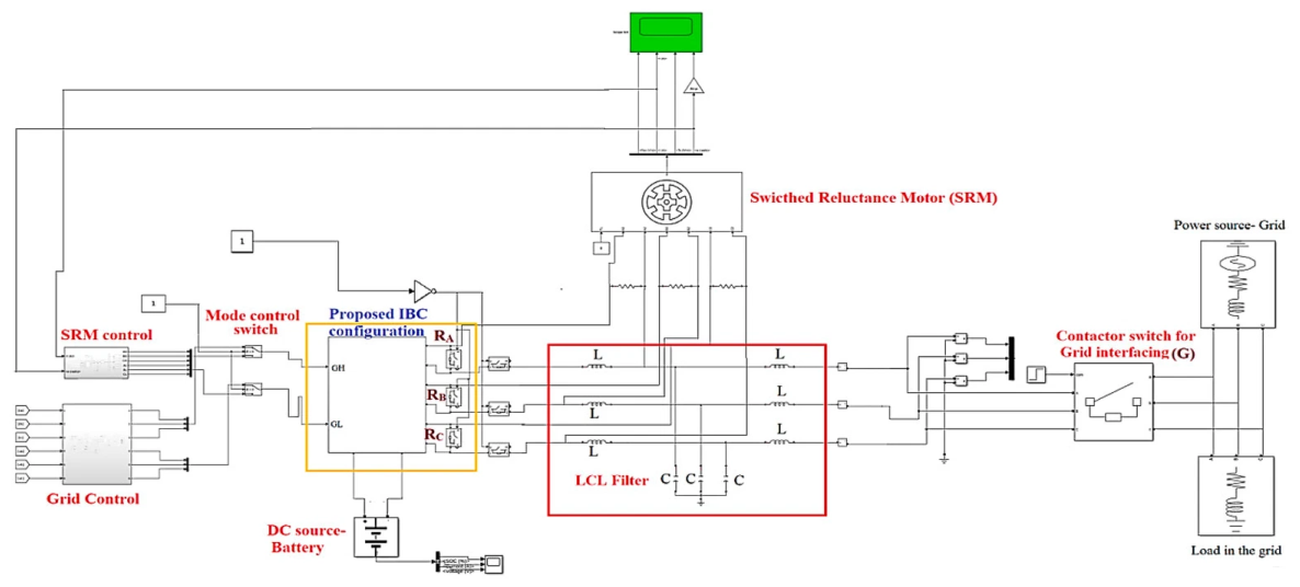
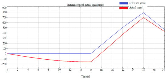
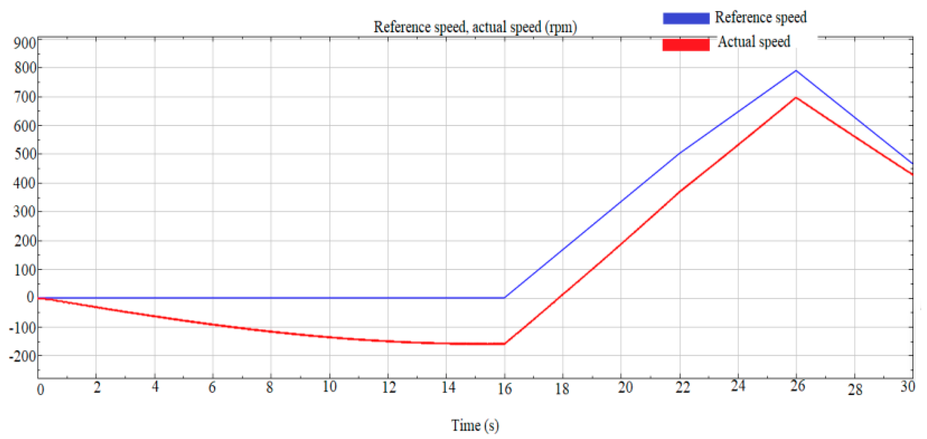
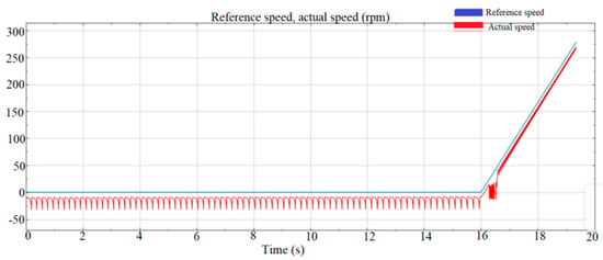
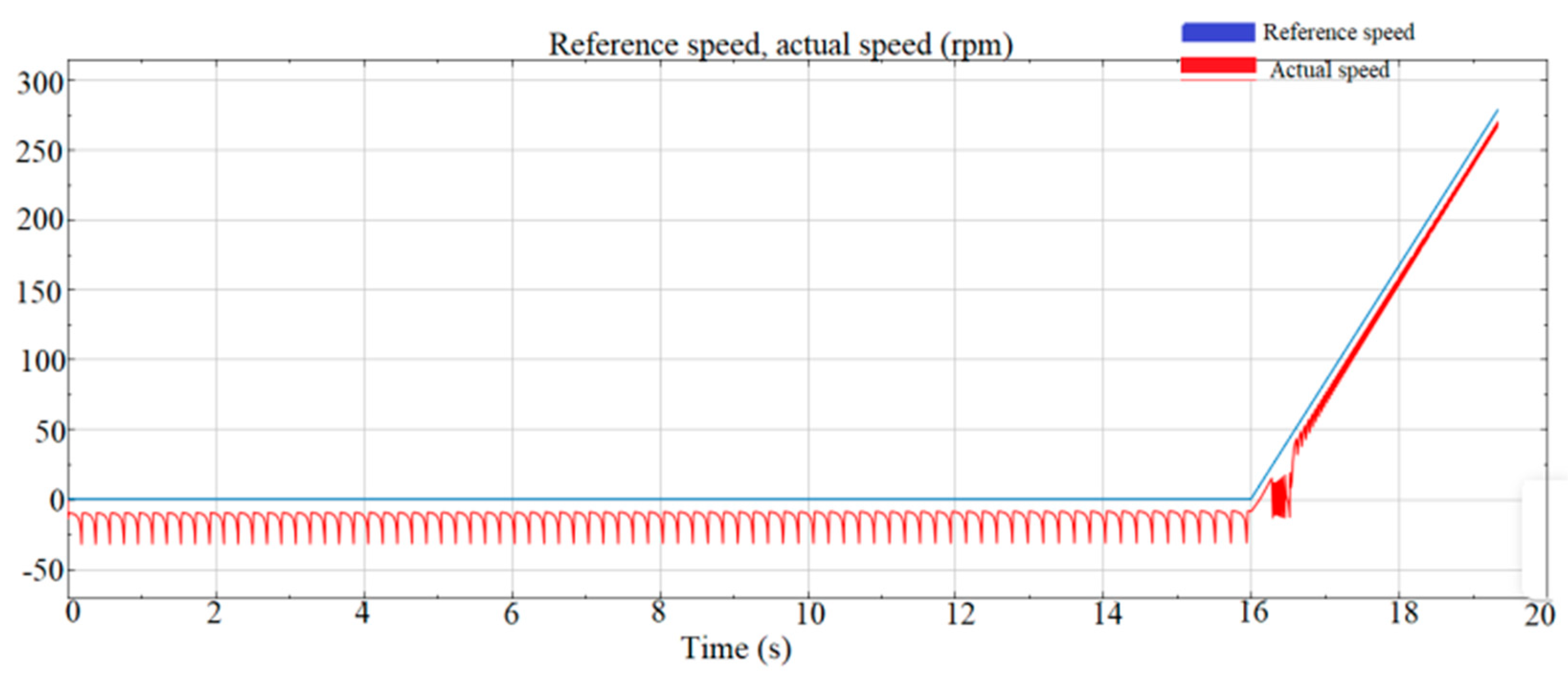
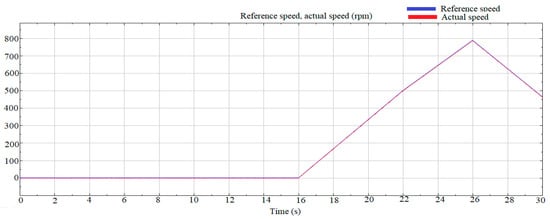
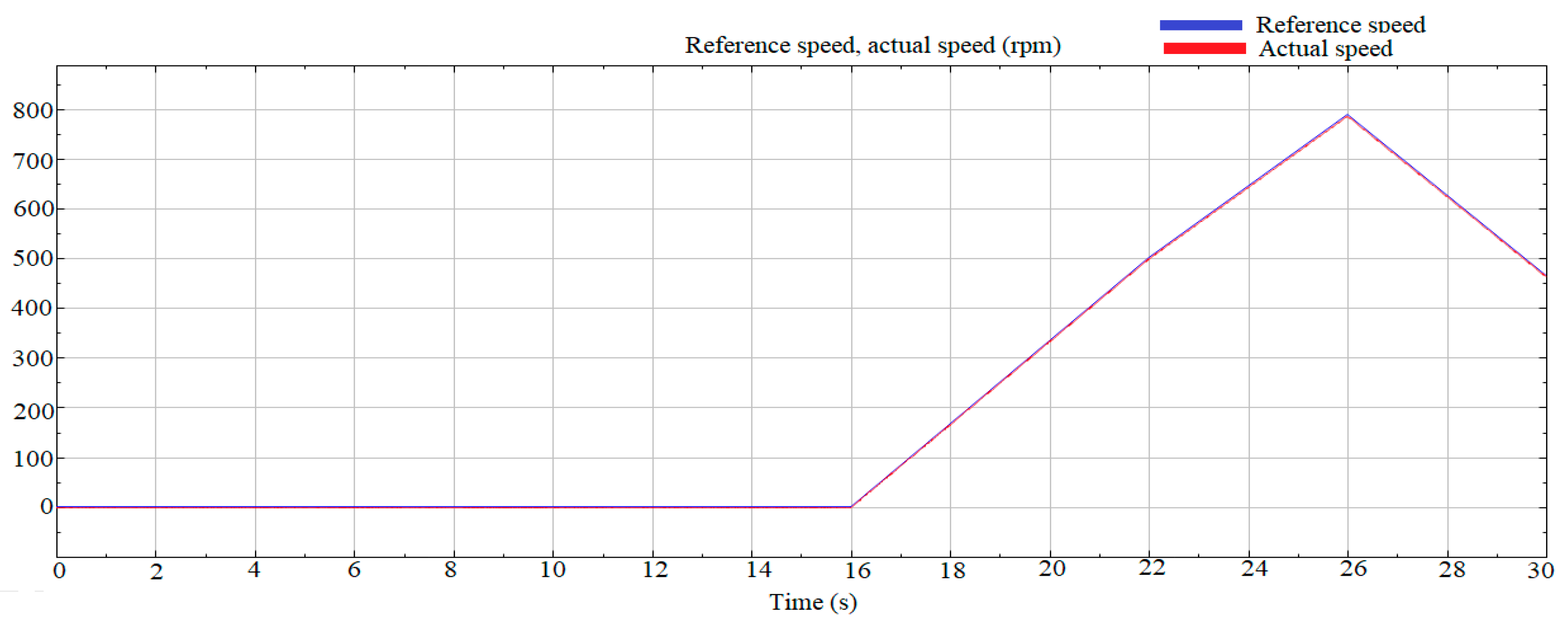
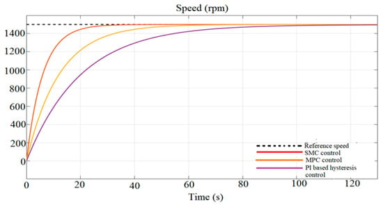
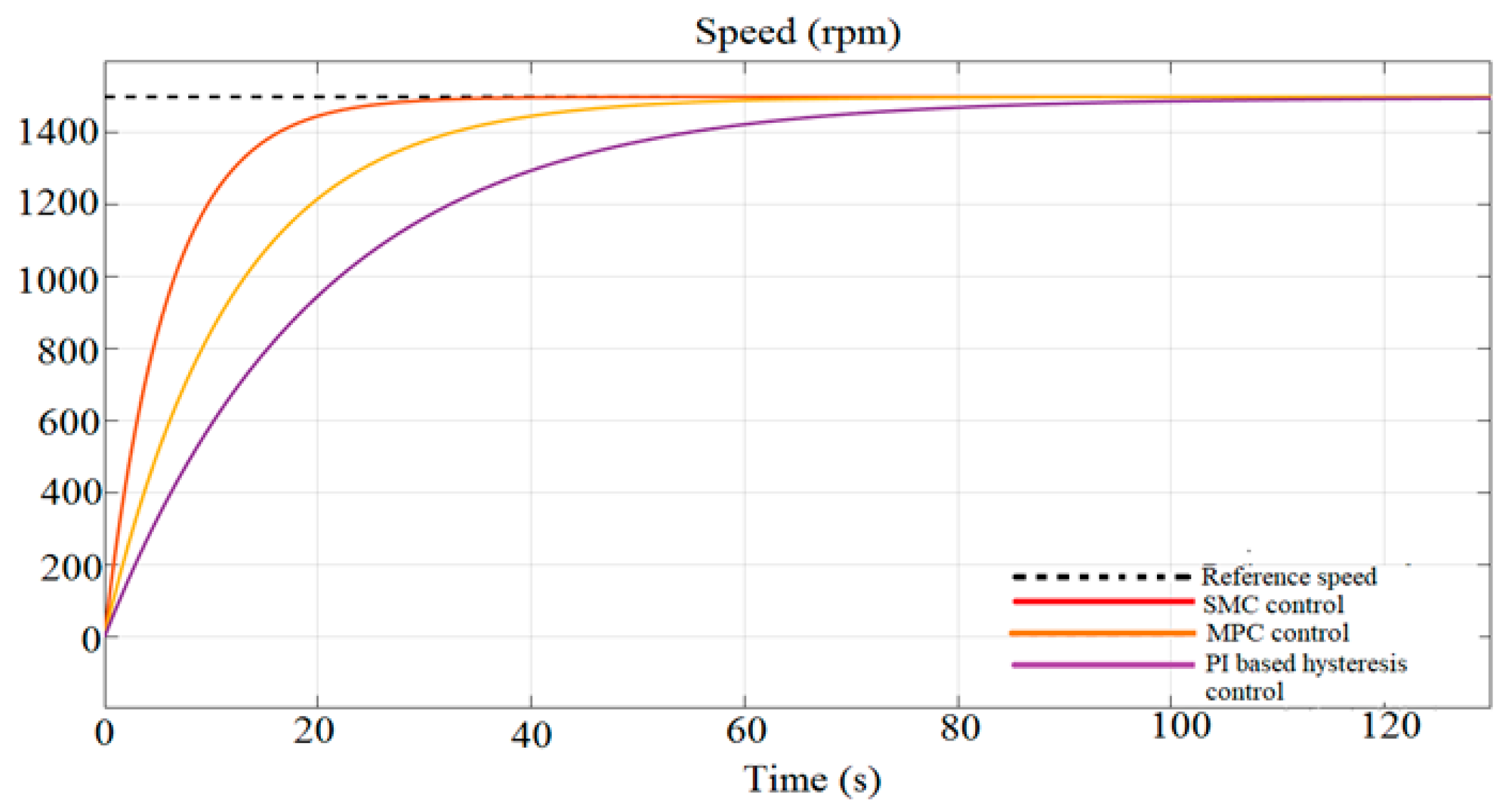
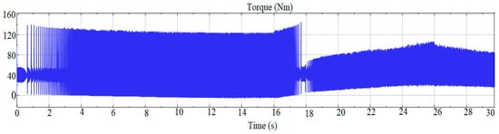
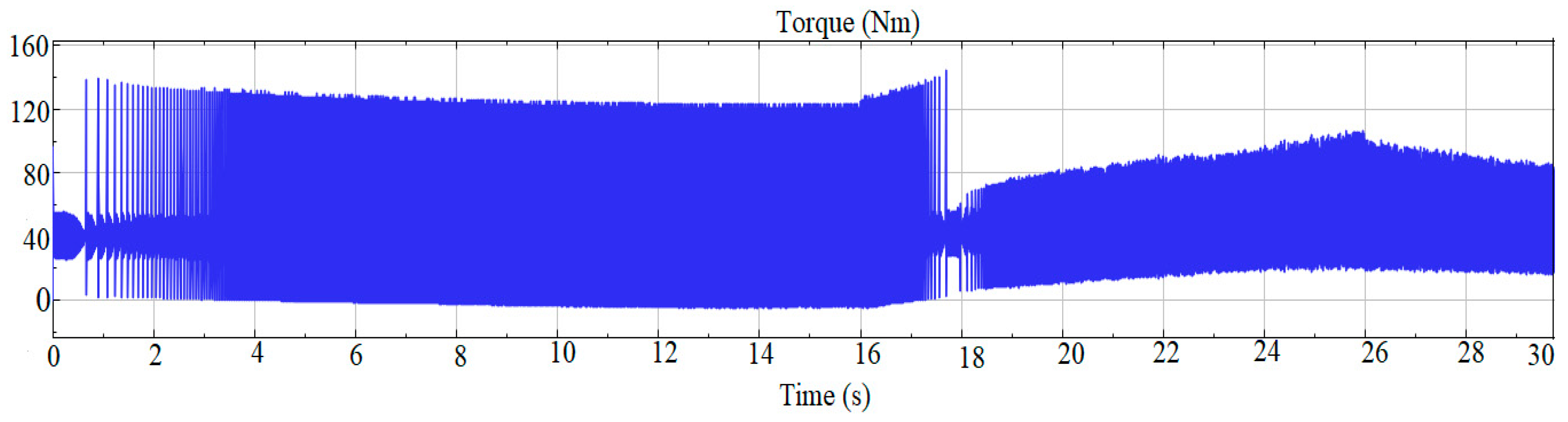
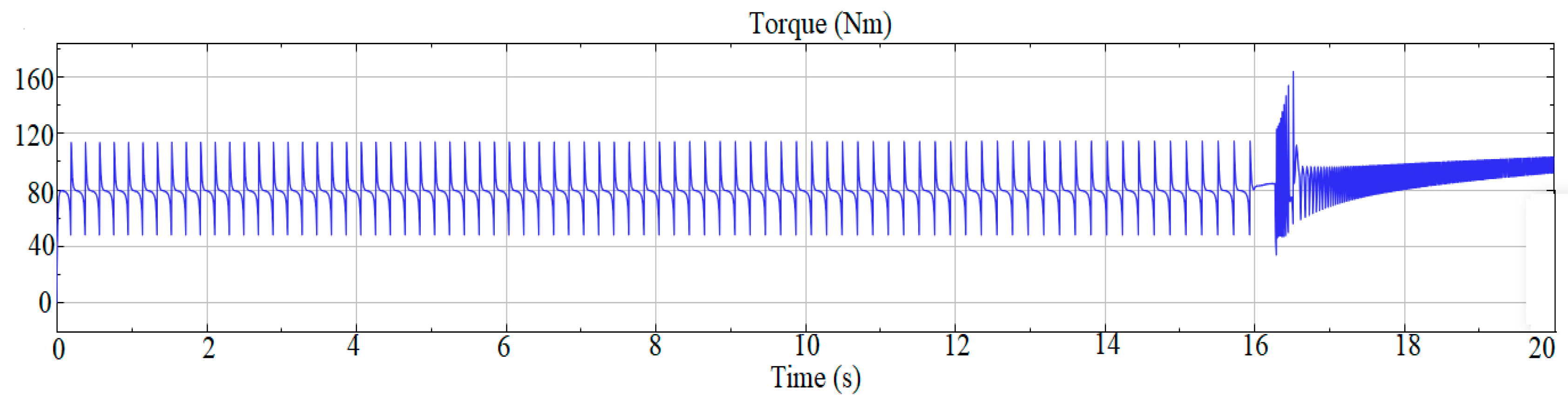
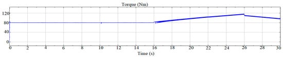
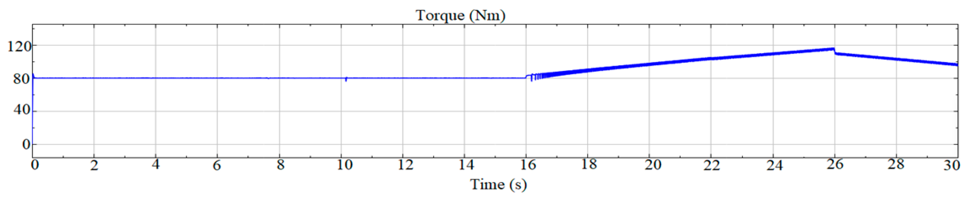
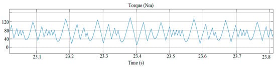
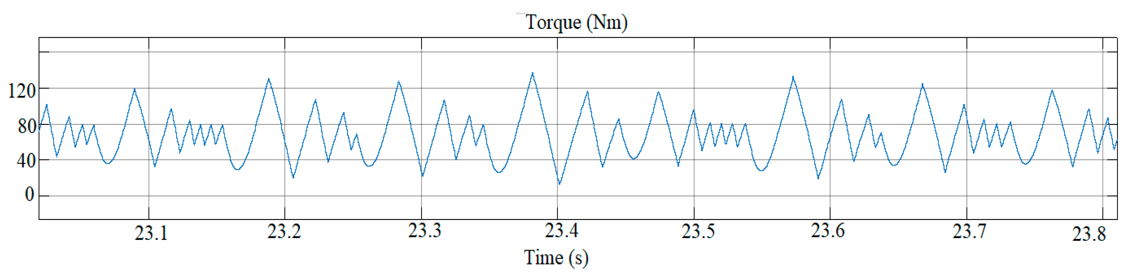
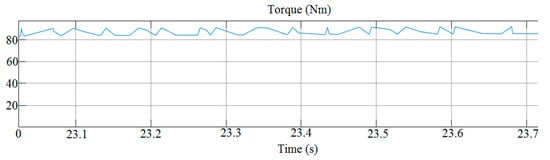
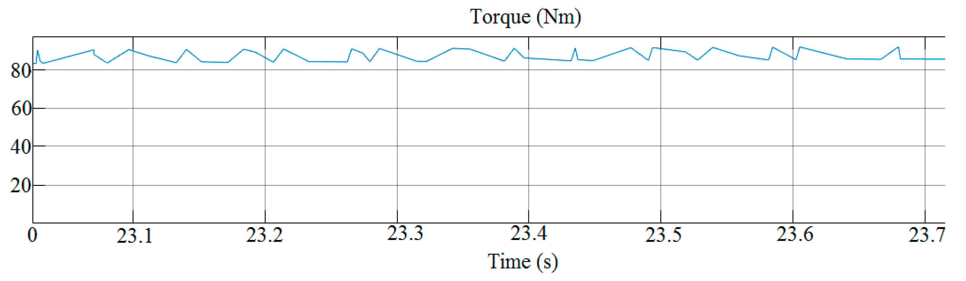
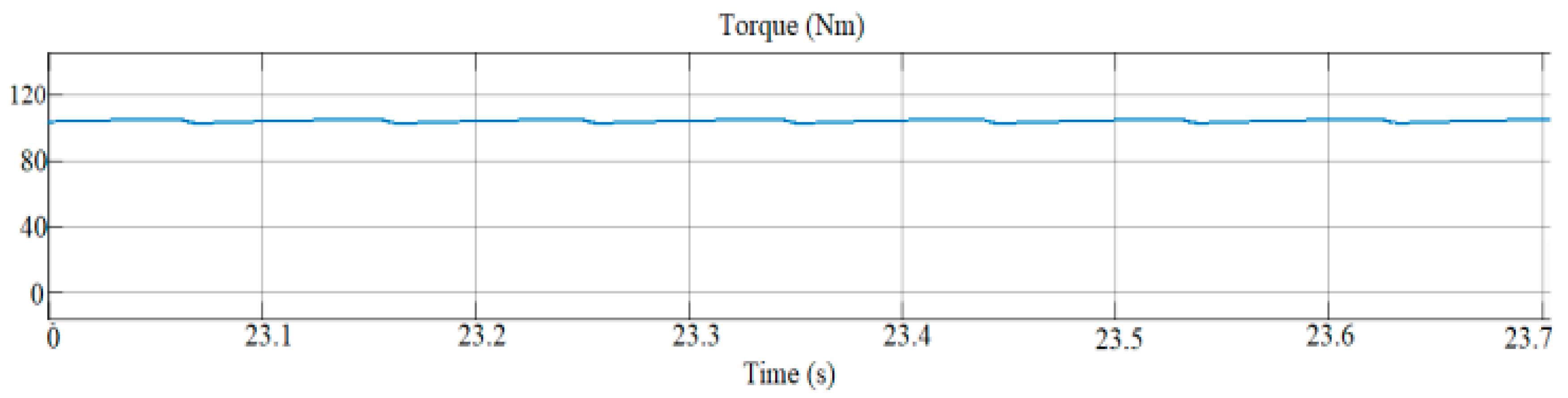
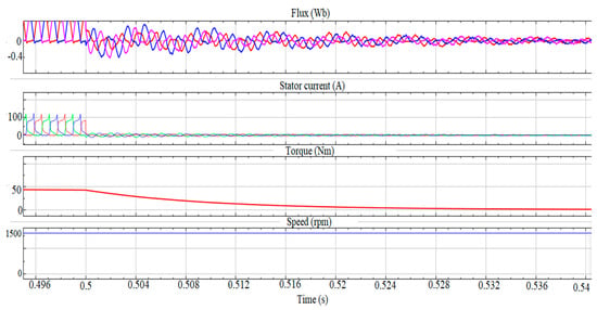
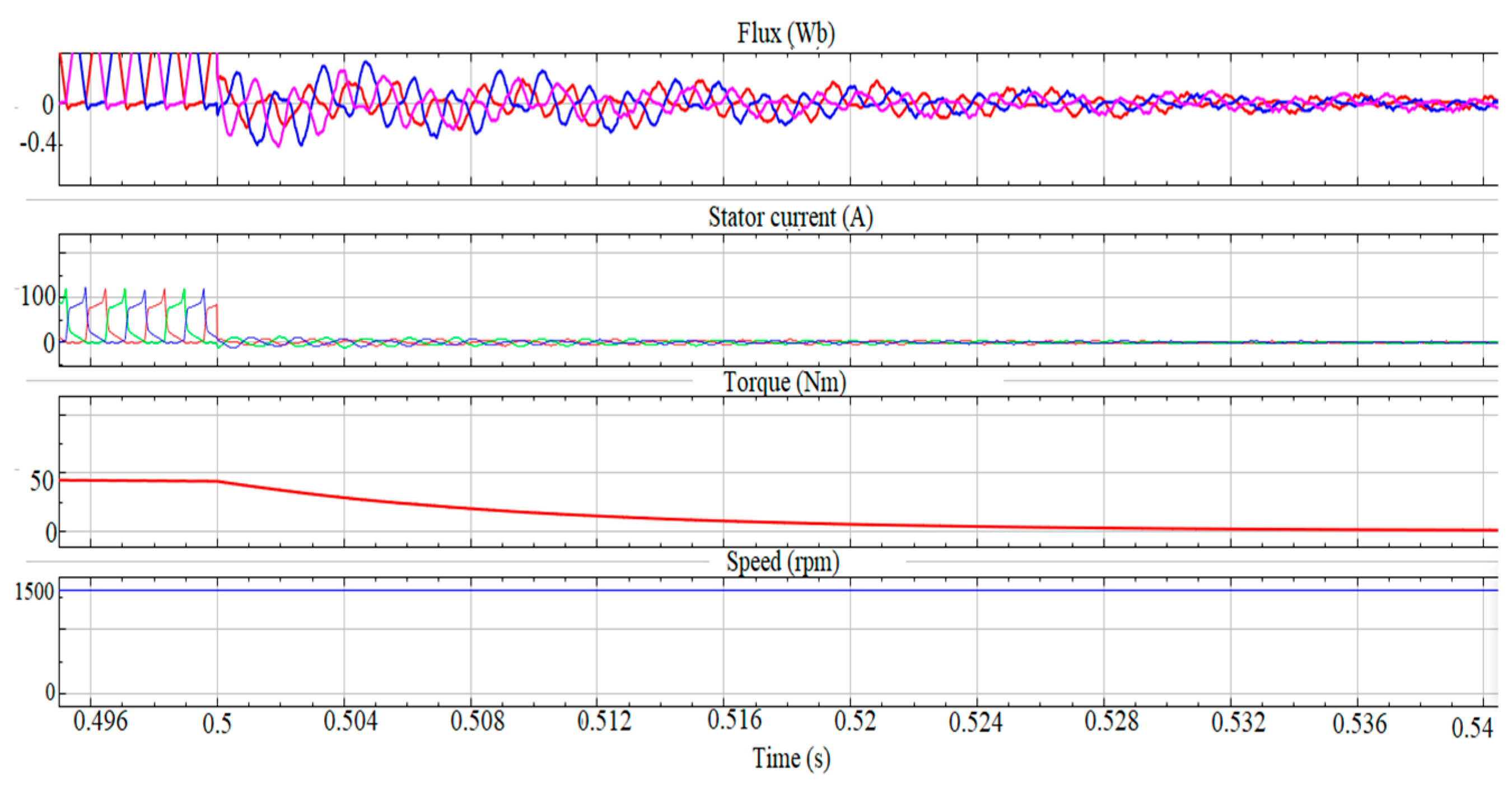
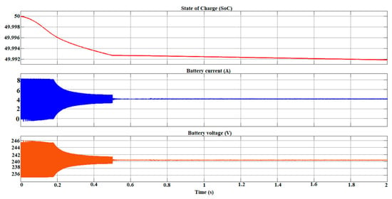
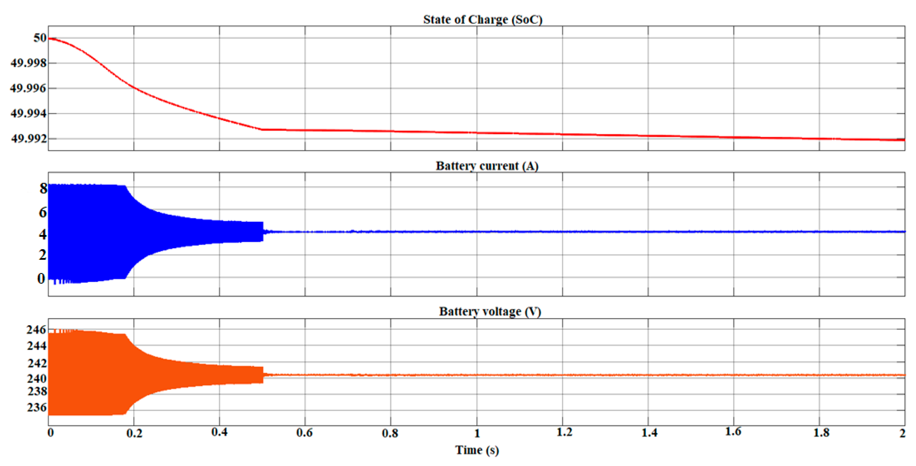
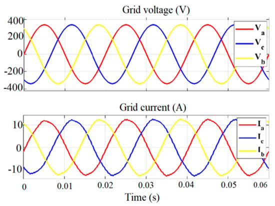
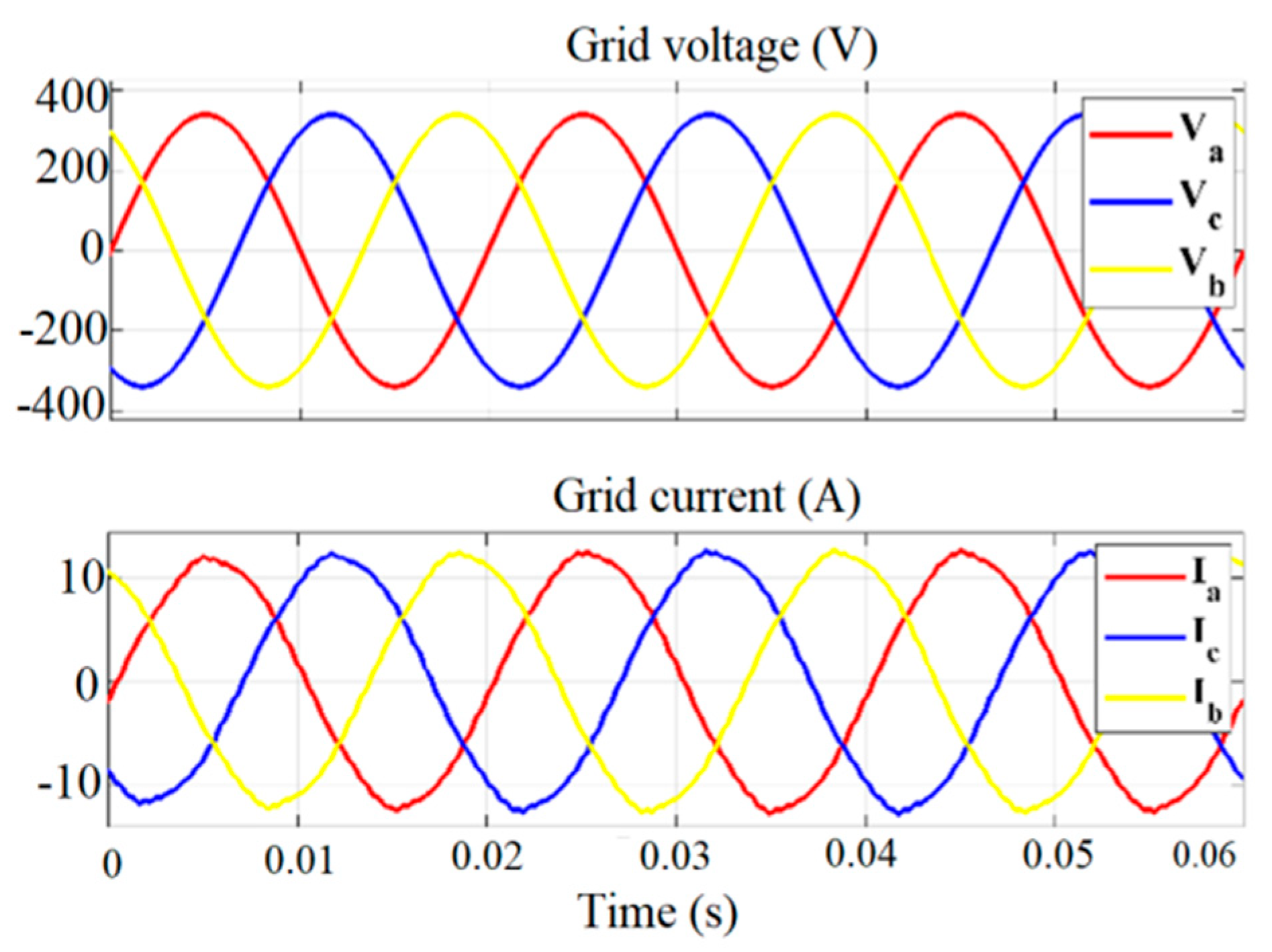
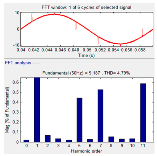
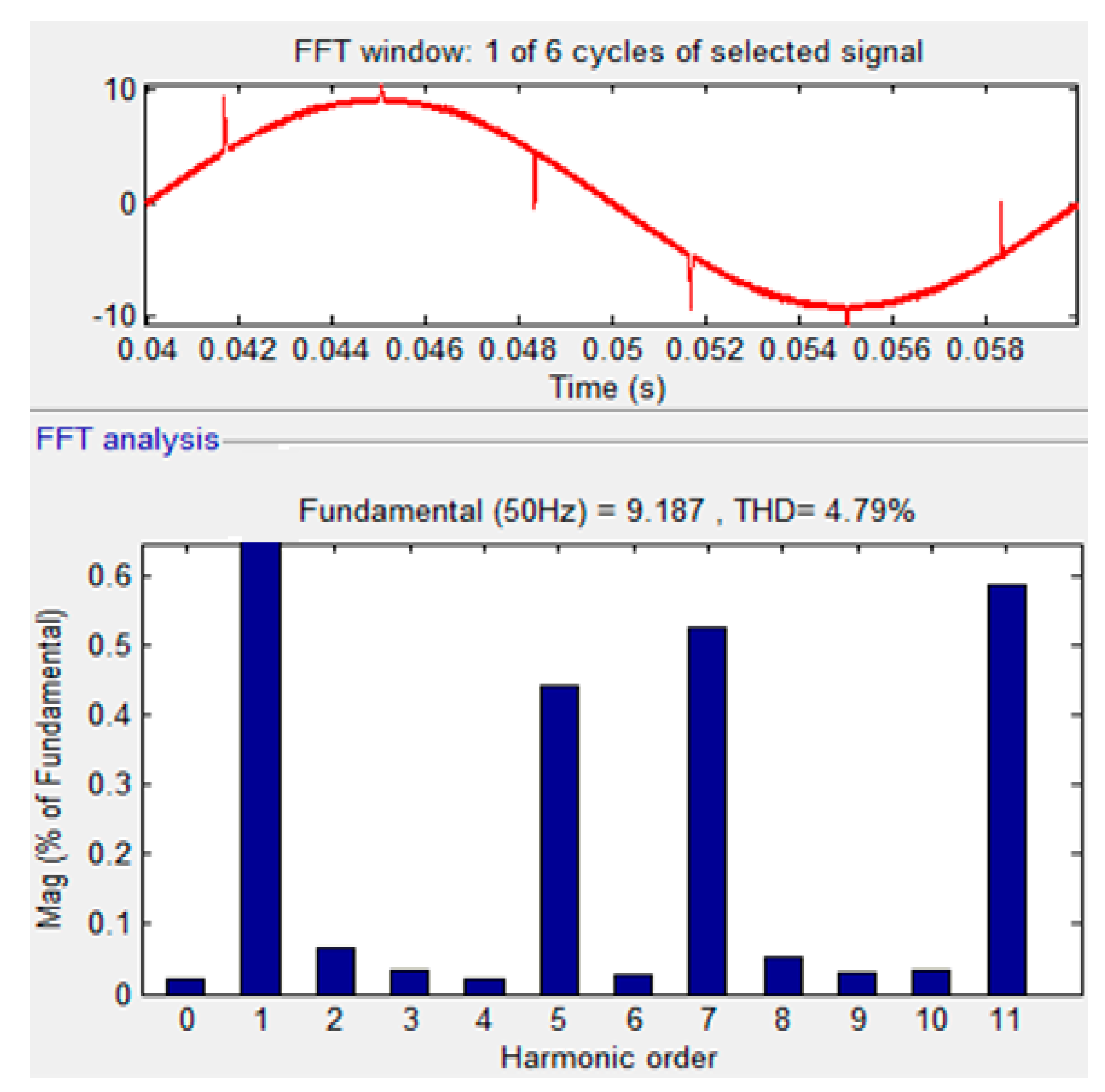
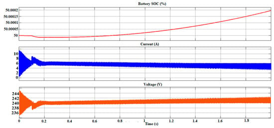
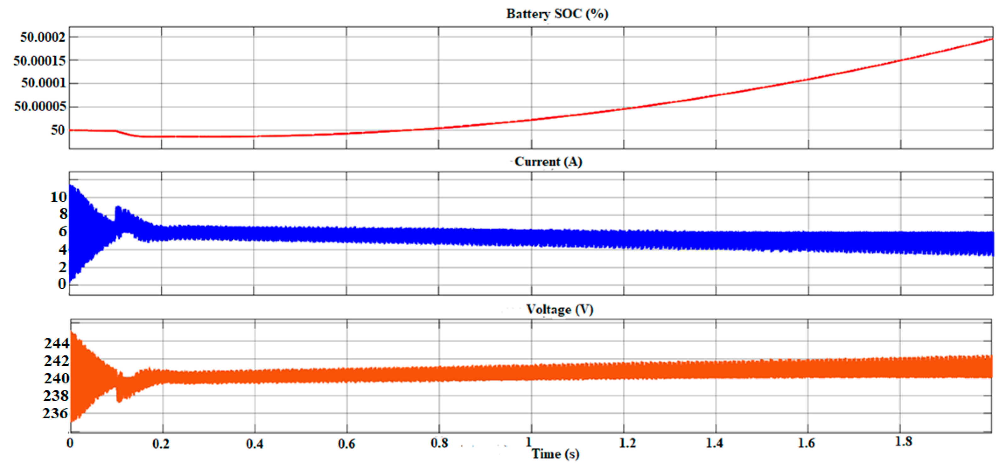
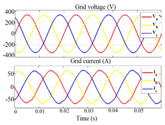
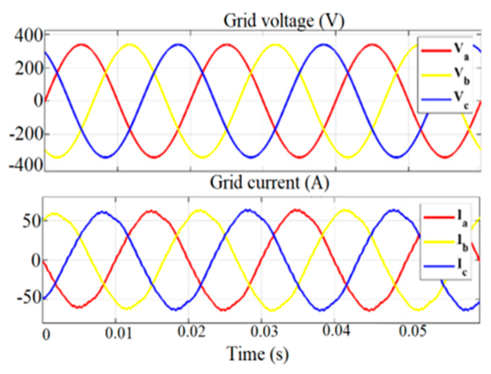
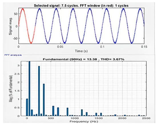
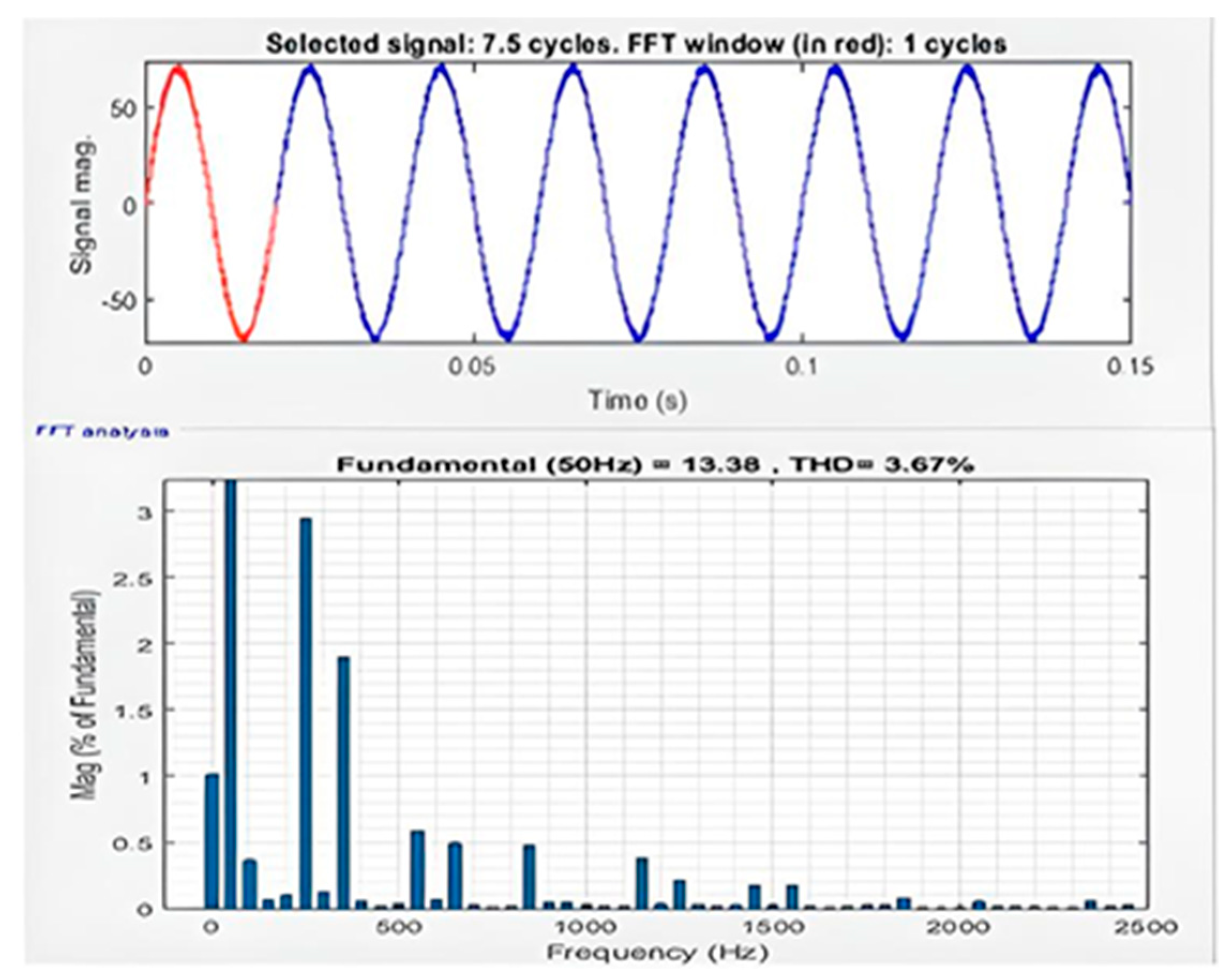
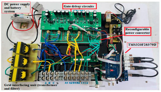
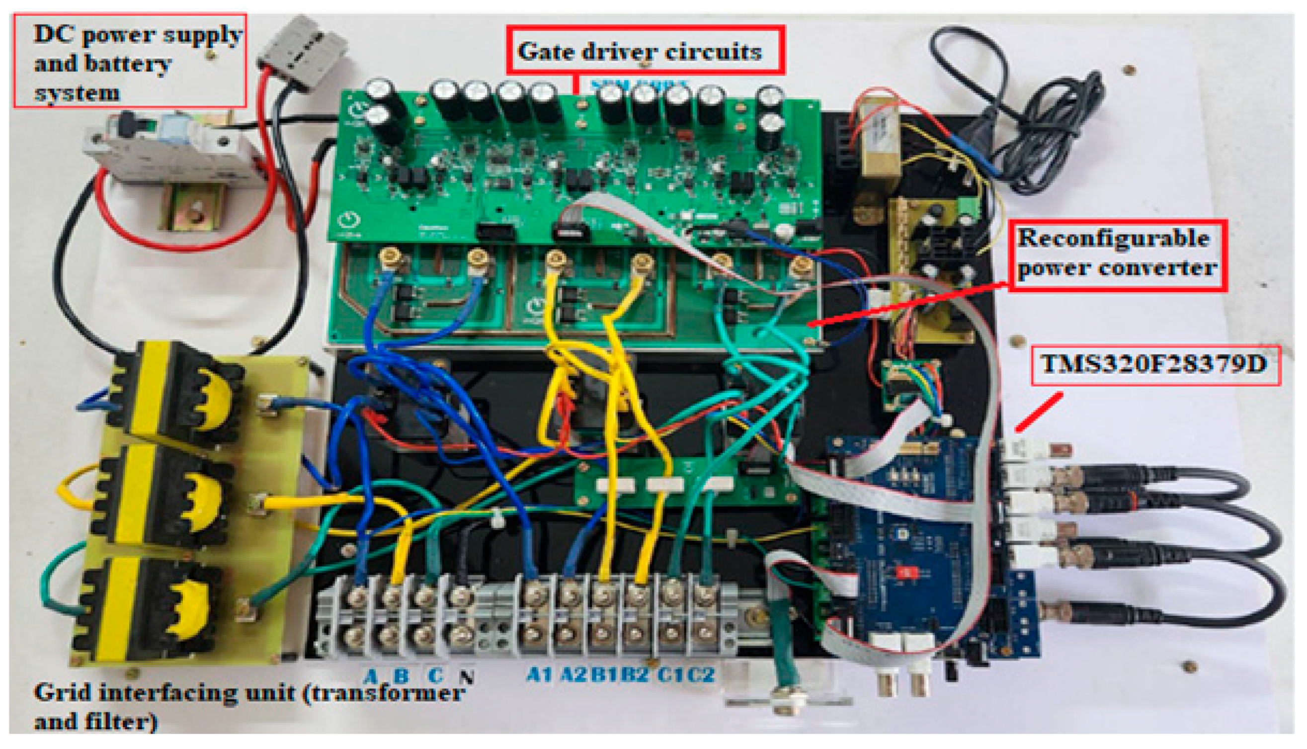
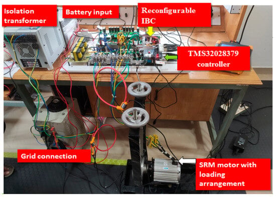
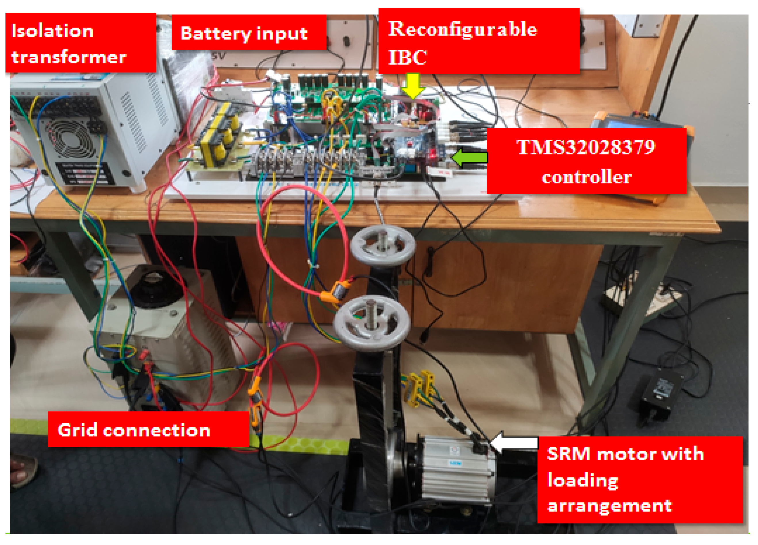
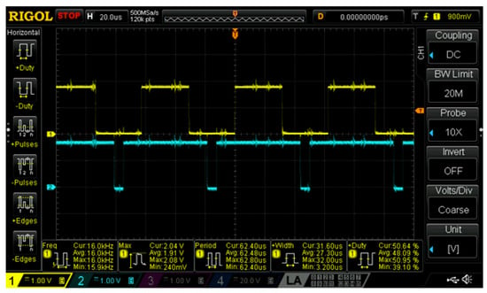
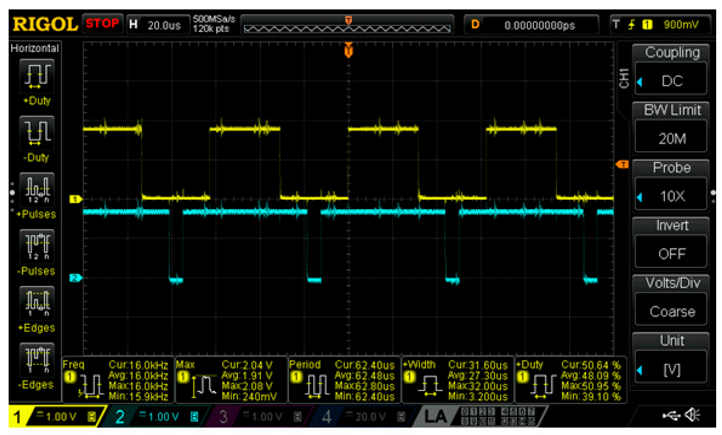
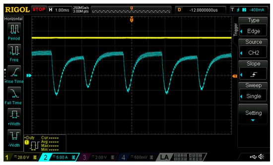
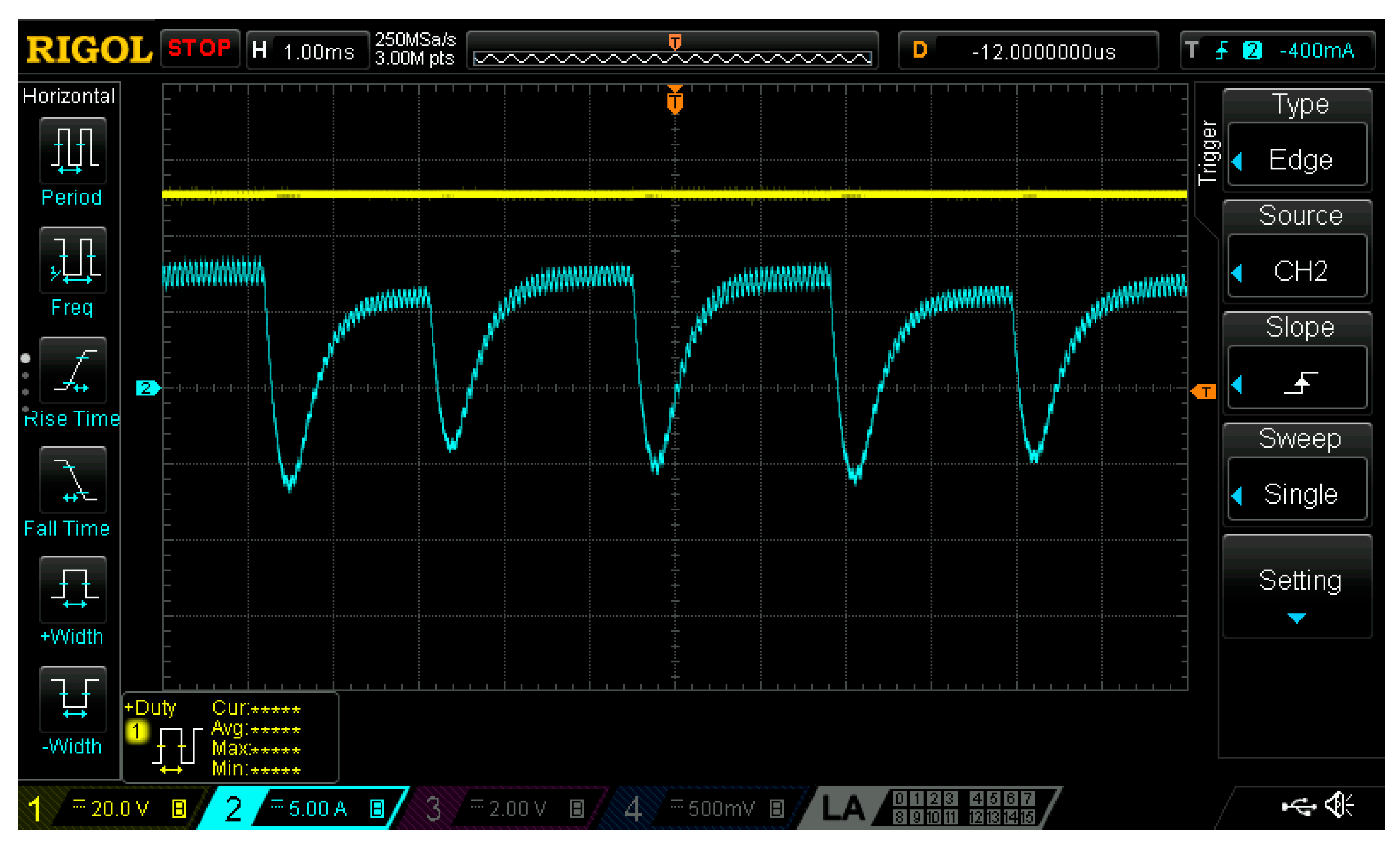
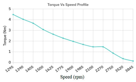
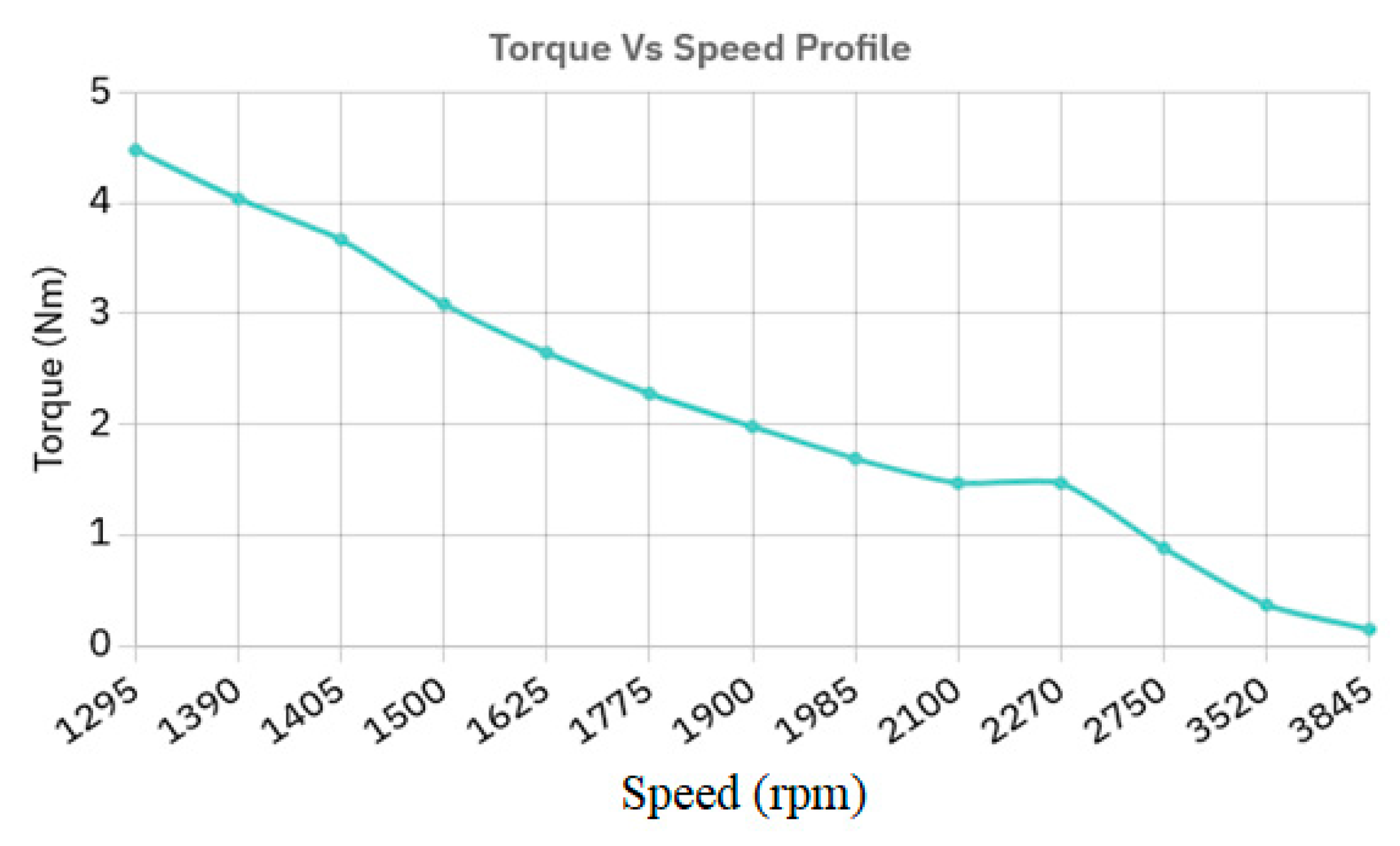
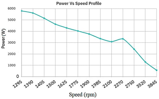
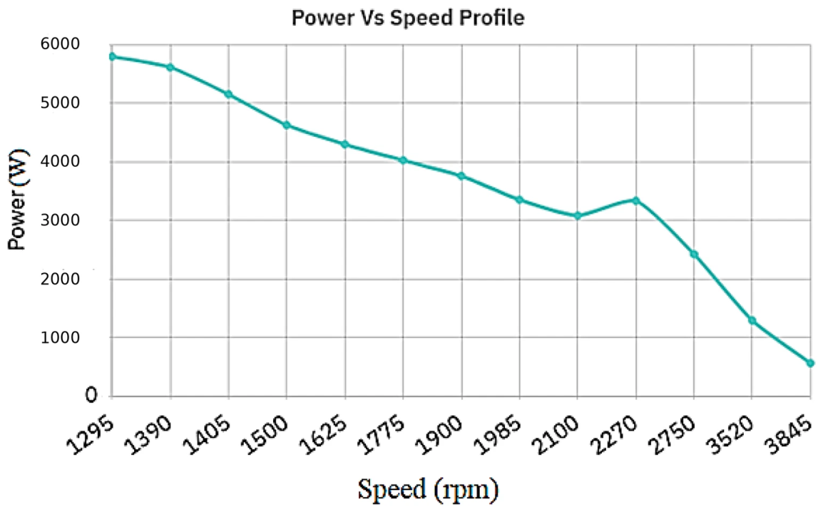
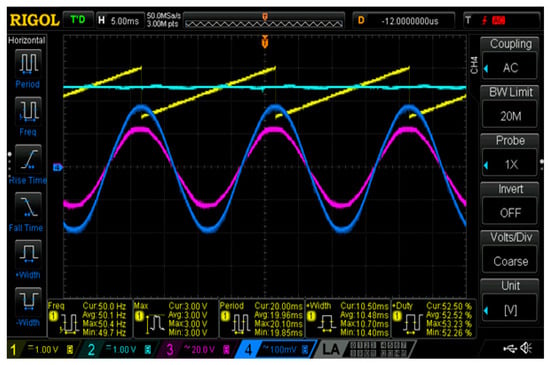
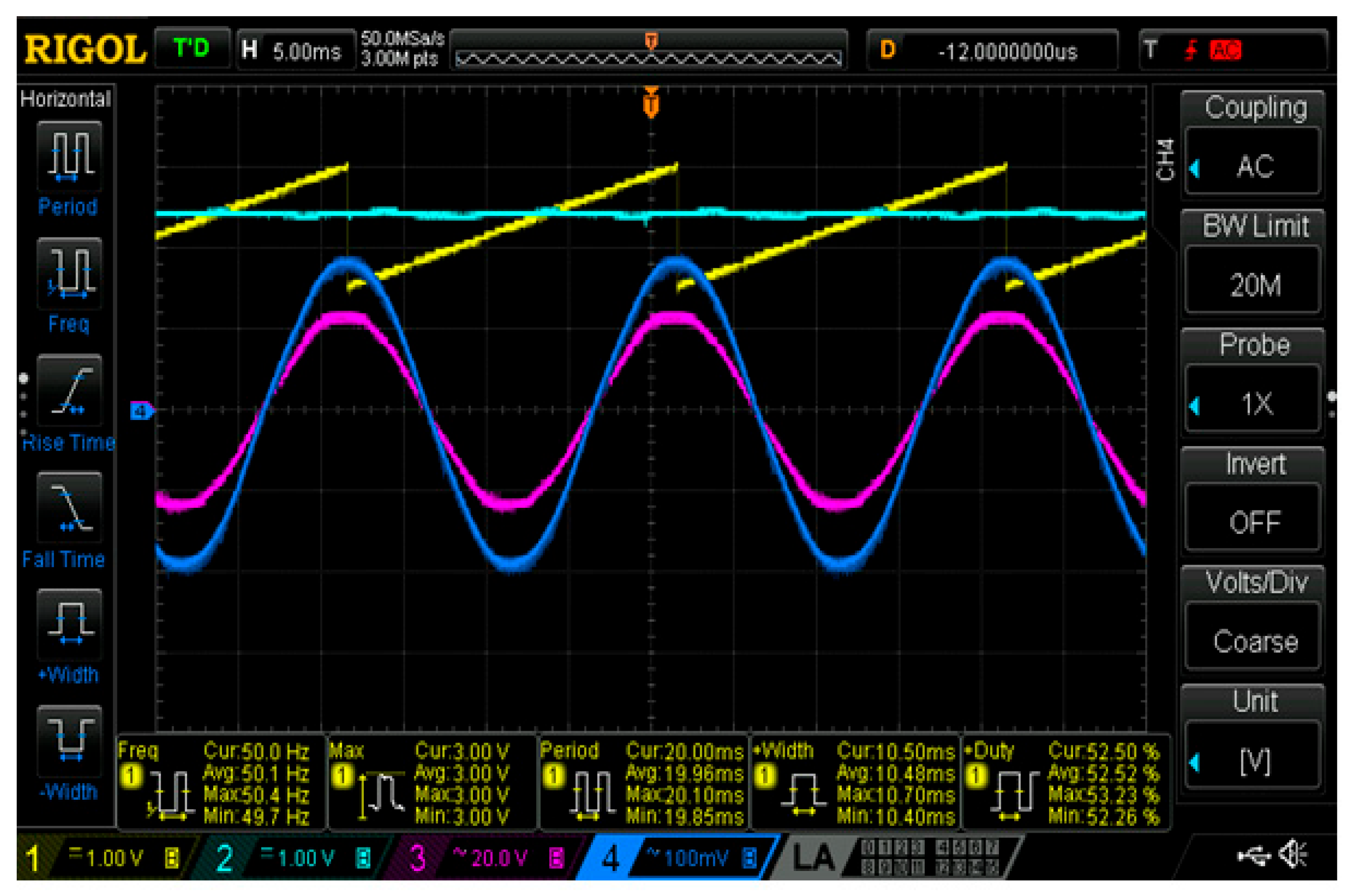
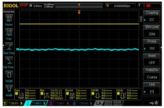
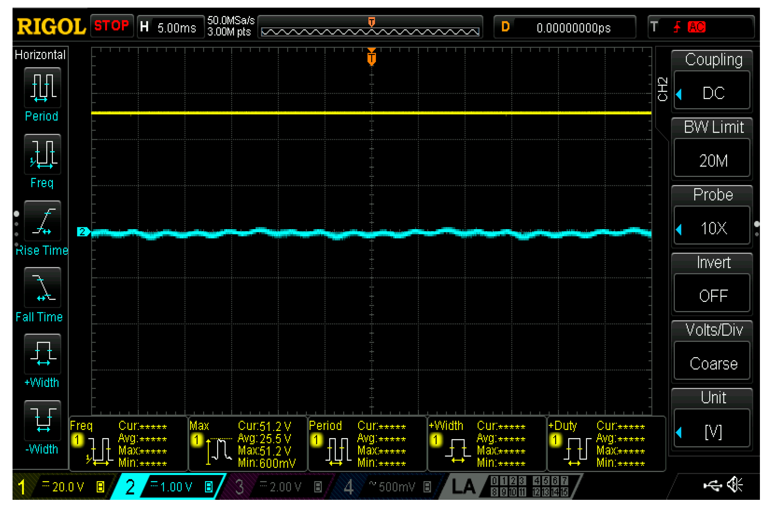
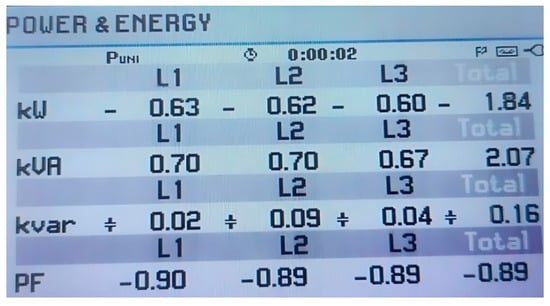
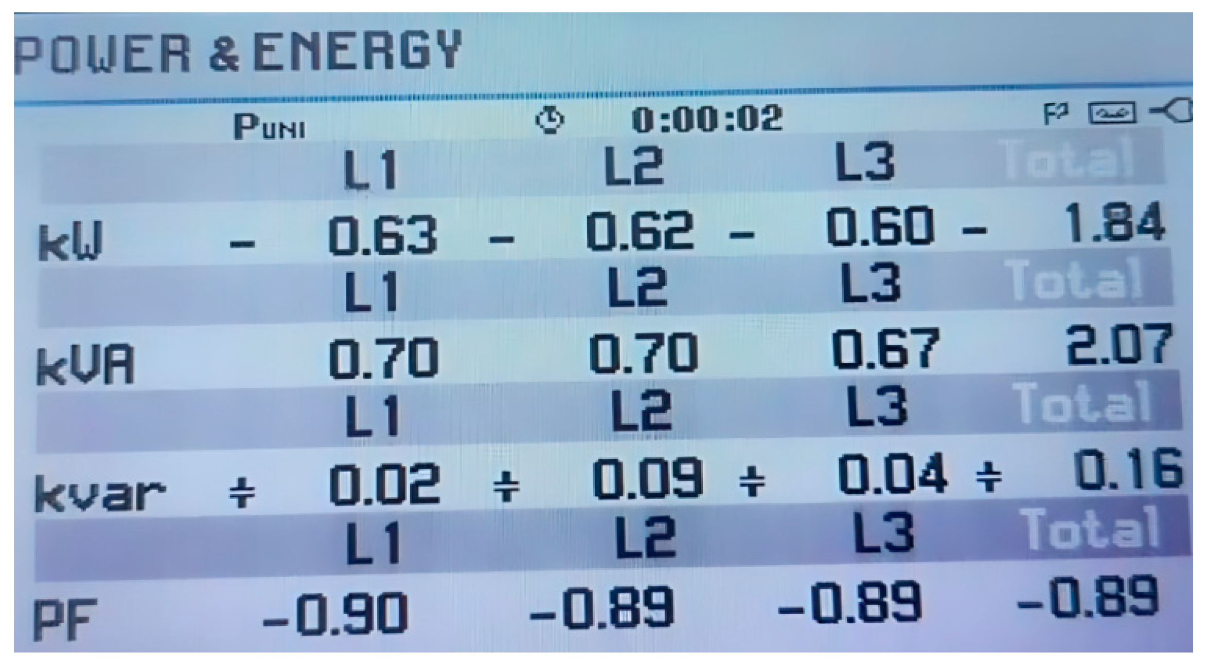
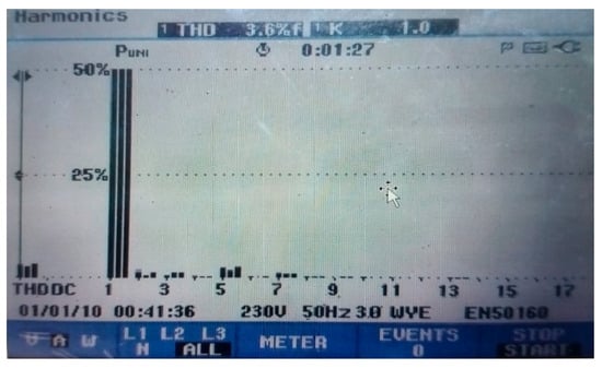
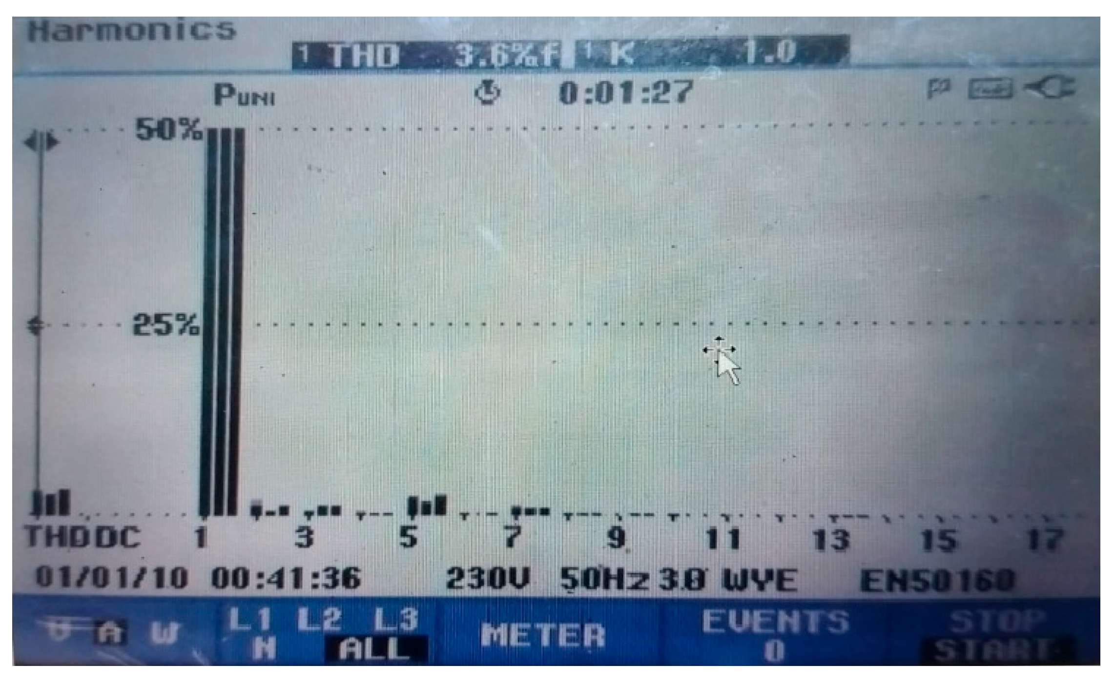
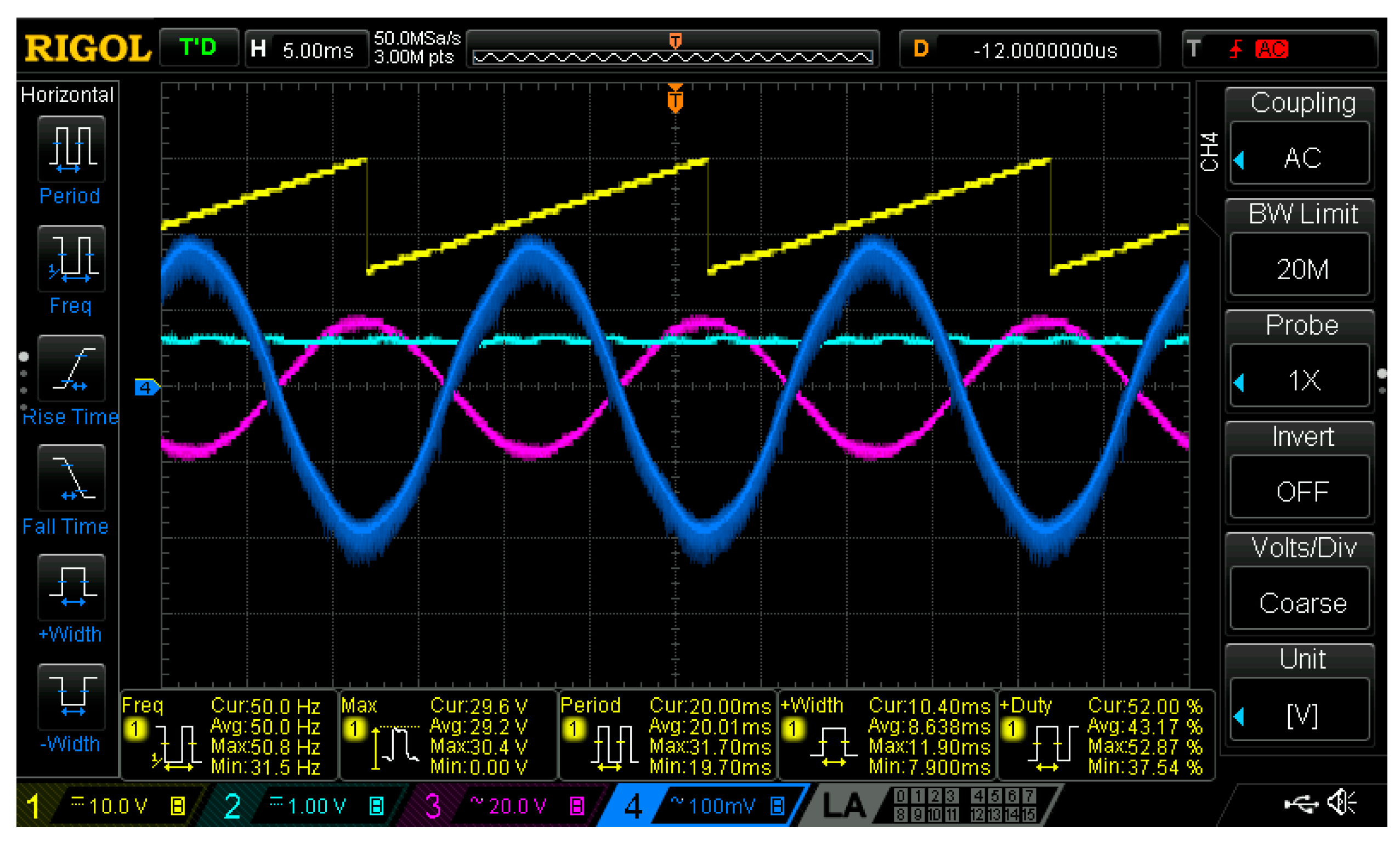
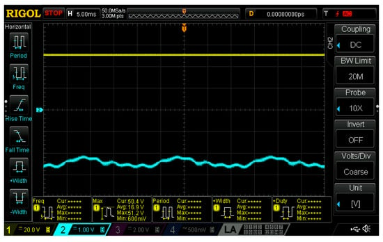
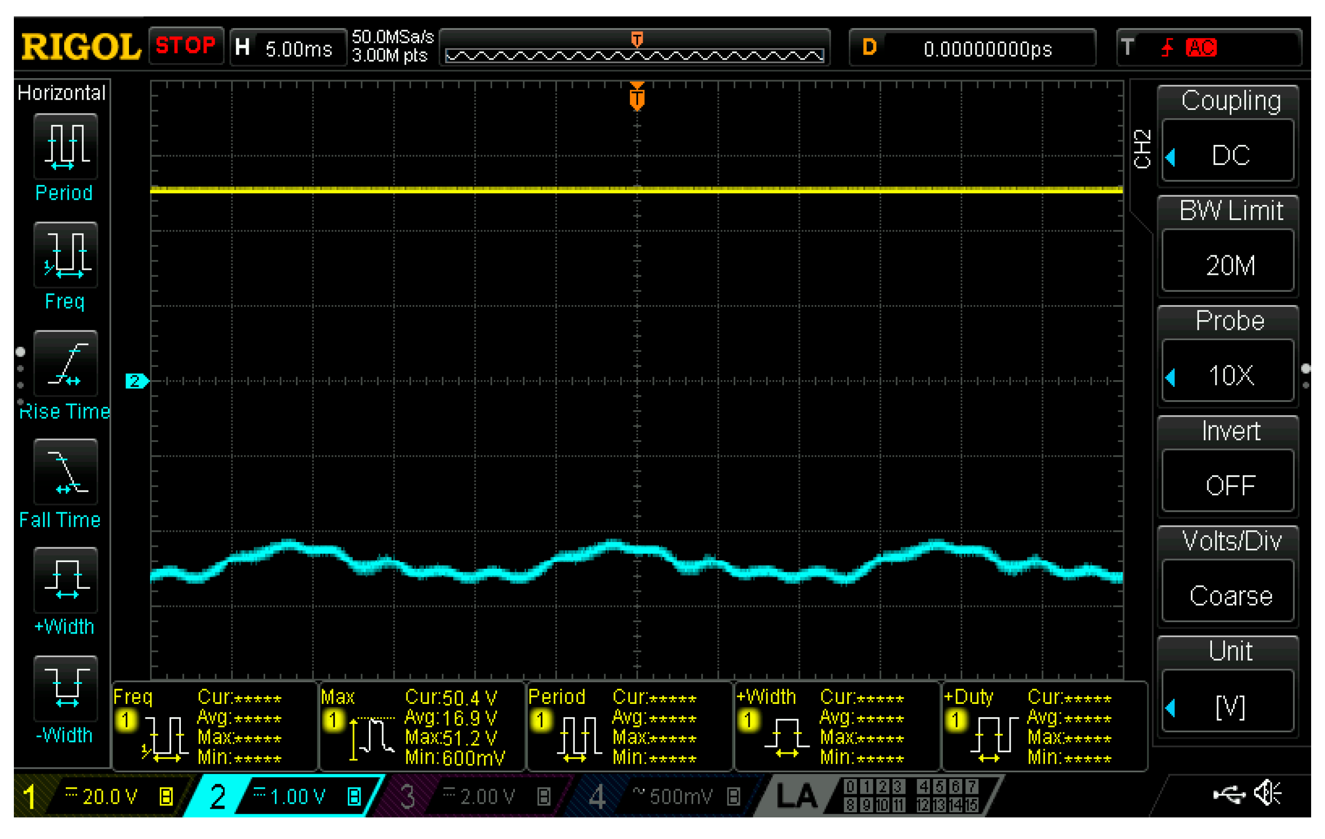
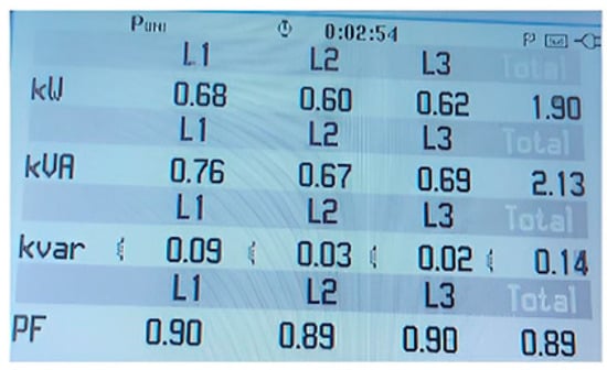
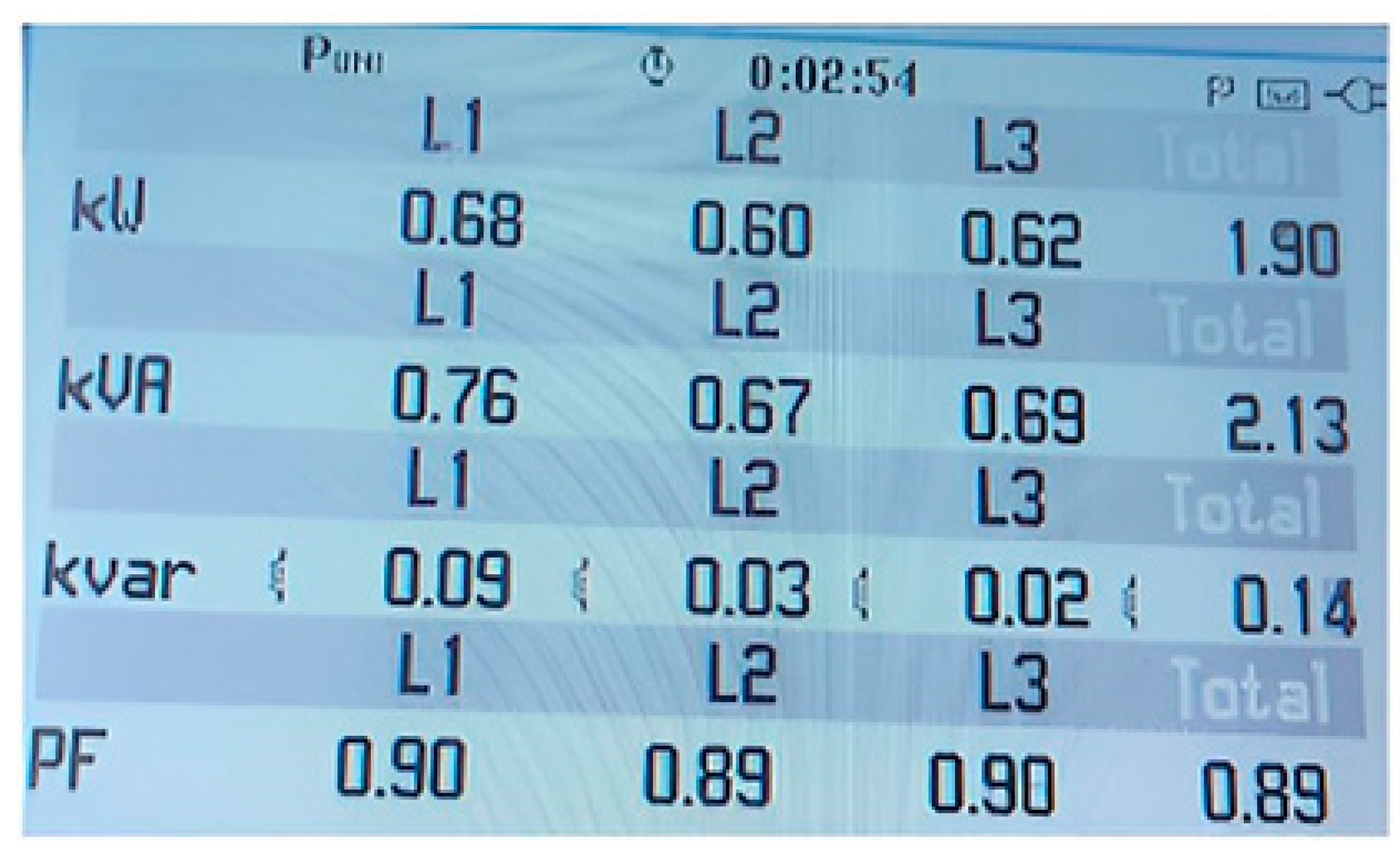
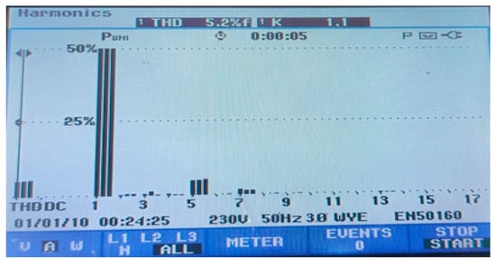
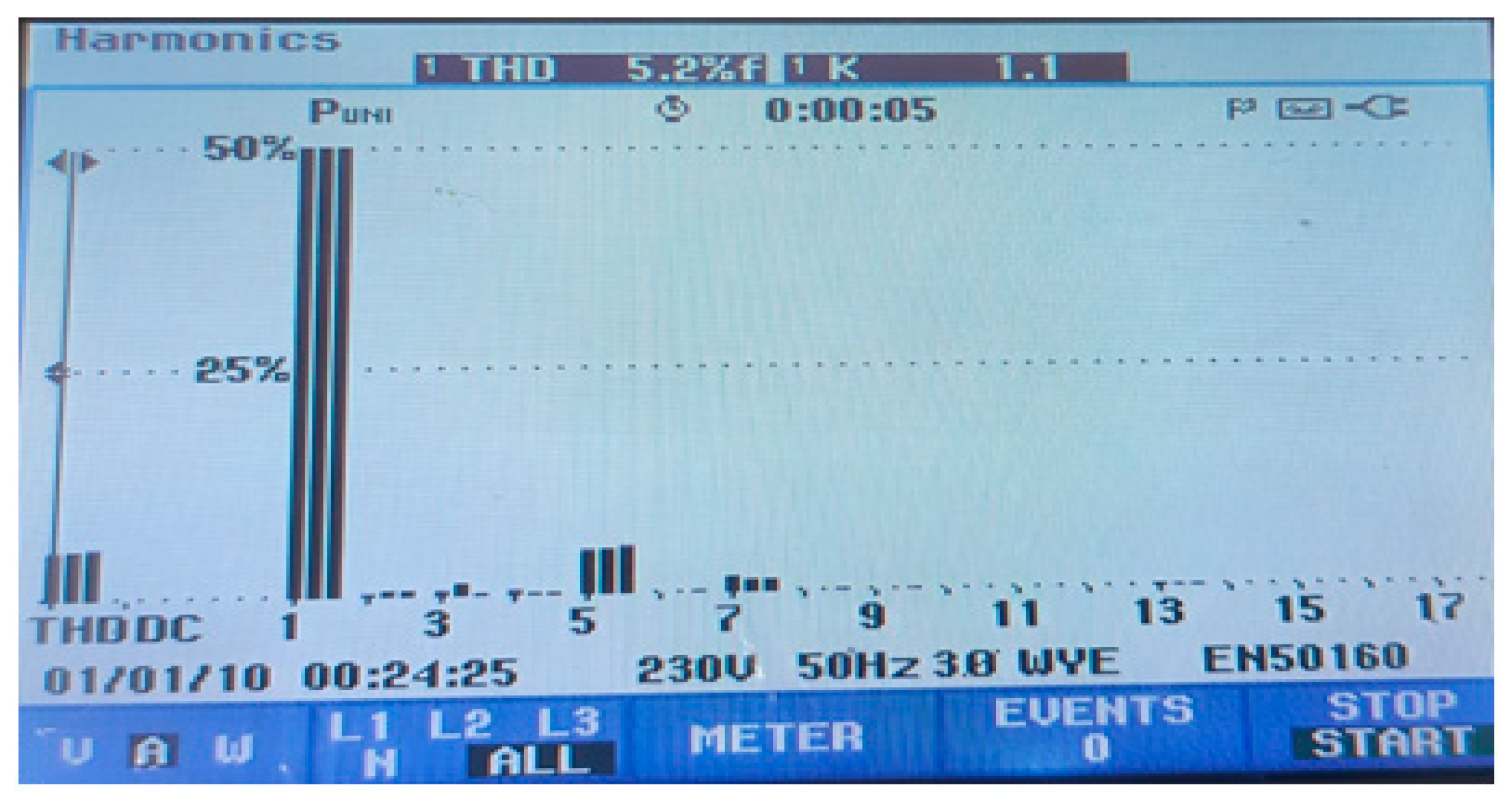

Disclaimer/Publisher’s Note: The statements, opinions and data contained in all publications are solely those of the individual author(s) and contributor(s) and not of MDPI and/or the editor(s). MDPI and/or the editor(s) disclaim responsibility for any injury to people or property resulting from any ideas, methods, instructions or products referred to in the content. |
© 2026 by the authors. Licensee MDPI, Basel, Switzerland. This article is an open access article distributed under the terms and conditions of the Creative Commons Attribution (CC BY) license.