


Abstract
This paper presents a theoretical and numerical extension of Budeanu’s power theory for three-phase three-wire systems supplied by symmetrical nonsinusoidal voltages and feeding unbalanced linear time-invariant loads. The proposed formulation combines the classical Budeanu framework with the Currents’ Physical Components (CPC) theory to provide a physical interpretation of Budeanu distortion power. Five mutually orthogonal components of the load current are distinguished, namely the active, scattered, Budeanu reactive, Budeanu-complemented reactive, and negative-sequence unbalanced currents. Consequently, Budeanu distortion power is shown to be an orthogonal combination of three powers (scattered, Budeanu-complemented reactive, and negative-sequence unbalanced) and not merely a residual obtained from the apparent, active, and reactive powers. The theoretical formulation is verified numerically using three illustrative delta-connected load configurations fed by a voltage composed of the 1st, 5th, and 7th harmonics. In all examples, the sum of the proposed components reproduces exactly the line currents calculated directly with Ohm’s law and Kirchhoff’s current law, and they distinguish the physical mechanisms responsible for each contribution to distortion power. The analysis is restricted to 3-p 3-w circuits fed by symmetrical nonsinusoidal voltages and loaded with linear time-invariant (LTI) elements, which are not sources of harmonics; consequently, it does not directly address asymmetrical supply conditions, four-wire systems, time-varying loads, or nonlinear loads with harmonic generation.
1. Introduction
The description of power properties in electrical circuits supplied by nonsinusoidal voltages and in unbalanced three-phase systems remains an important issue in electrical engineering. This issue has acquired particular relevance due to the increasing presence of power-electronic converters, nonlinear loads, distributed energy resources, and other devices that modify voltage and current waveforms in electrical power systems [1,2,3,4,5,6,7]. In these circumstances, classical power relations may fail to account for the growth of the supply-current RMS value, the deterioration of the power factor, and the occurrence of additional effects associated with waveform distortion and load unbalance [4,5,6,7,8,9,10,11].
Budeanu’s theory, proposed in 1927 [1], is among the earliest frequency-domain power theories and has had a lasting influence on the field. It defined active, reactive, and distortion powers for circuits in which voltages and currents are nonsinusoidal. Its formal simplicity contributed to its widespread use; however, the physical interpretation of Budeanu reactive power and, in particular, Budeanu distortion power has been questioned for several decades [4,5,6,7]. In the original formulation, Budeanu distortion power is obtained as a residual quantity from the apparent, active, and reactive powers. Consequently, its value does not identify the physical phenomena in the circuit or the equivalent load parameters that cause the related rise in the current RMS value [4,5,7].
The issue remains relevant because Budeanu’s quantities have been repeatedly reinterpreted and compared with alternative approaches to the description of power under nonsinusoidal conditions [12,13]. Contemporary research on frequency-domain non-active-power decompositions also demonstrates that the definition, terminology, and physical interpretation of non-active current and power components remain active research topics [14]. Therefore, a power theory intended for the analysis of practical three-phase systems should not only calculate aggregate quantities but also distinguish the physical mechanisms that produce non-active current components.
The Currents’ Physical Components (CPC) theory proposed by Czarnecki [2,8,9,10,11,13,15] offers a description based on physical phenomena. In this theory, the current components are related to equivalent load parameters and to distinct power-related phenomena. The CPC approach has been developed for single-phase and three-phase systems, including systems supplied by nonsinusoidal and asymmetrical voltages [13,15,16,17,18,19]. In particular, the analysis of three-phase systems requires the circuit to be treated as a whole rather than as three independent single-phase circuits. Such an approach is necessary for a consistent description of apparent power, current components, power factor, and the effects of load unbalance [15,16,17].
The application of CPC theory to three-phase three-wire systems is especially important because the absence of a neutral conductor changes the structure of admissible current components and the interpretation of load unbalance. In this class of circuits, a physically meaningful power description must distinguish the effects of active energy transfer, conductance variation with harmonic order, reactive properties of the load, and negative-sequence unbalance [10,15]. These properties cannot be fully represented by the original Budeanu formulation, which provides only the total values of active power, Budeanu reactive power, and residual distortion power.
In the authors’ previous works, the Budeanu formulation was extended to single-phase systems [20]. The extension was later developed for three-phase four-wire systems supplied by a symmetrical nonsinusoidal voltage, where the current of an unbalanced load was represented by seven mutually orthogonal components [21]. In contrast to the four-wire case, the absence of the neutral conductor in three-phase three-wire systems eliminates the path for zero-sequence currents and reduces the number of mutually orthogonal current components to five; the differences between these formulations are discussed in Section 6.7.
Road-lighting installations based on LED luminaires constitute an important practical field in which the analysis of electrical quantities under nonsinusoidal operating conditions is increasingly relevant. The electronic drivers incorporated in modern LED luminaires, particularly under dimming operation or within smart-control schemes, can affect the power factor, reactive-power demand, and harmonic spectrum of the current drawn from the supply network [22,23,24,25,26]. Laboratory and field studies have also shown that the current harmonics and power demand of LED luminaires depend on the level and harmonic distortion of the supply voltage [27,28], and that power-quality aspects should be assessed already at the pre-evaluation stage of outdoor-lighting renewal projects [29]. These phenomena may deteriorate power-quality indices, contribute to additional active-power losses in supply conductors, and affect the energy performance of the overall installation [22,23,24,25,26,30]. In particular, limiting reactive-power flows in lighting installations has been shown to reduce active-power losses, highlighting the practical importance of reactive-power management and compensation [30]. Moreover, comprehensive energy audits of road-lighting systems enable the identification of technical and operational measures that reduce energy intensity and support the effective modernization of existing installations [31]. In this context, the extended Budeanu theory provides a useful framework for separating non-active effects associated with reactive-power transfer, frequency-dependent load parameters, and load asymmetry. Such a decomposition can support the interpretation of measured current and power quantities, the identification of dominant mechanisms responsible for the increase in apparent power, and the selection of appropriate compensation or operating measures in LED road-lighting installations.
The present work extends this research line to three-phase three-wire systems supplied by symmetrical nonsinusoidal voltages and feeding unbalanced linear time-invariant loads. The proposed formulation combines the common elements of the classical Budeanu theory and the CPC theory. Within this formulation, the load current is split into five mutually orthogonal parts: the active, scattered, Budeanu reactive, Budeanu-complemented reactive, and negative-sequence unbalanced currents. It is further shown that, in the considered 3-p 3-w systems, Budeanu distortion power is not an unspecified residual but consists of three parts: the scattered, Budeanu-complemented reactive, and negative-sequence unbalanced powers.
The paper is structured as follows. In Section 2, the CPC description of a 3-p 3-w circuit with a symmetrical nonsinusoidal supply is recalled, together with the current components and powers that serve as the physical reference for the extension. Section 3 combines the circuit-theory description and the classical Budeanu formulation. It first describes the calculation of branch and line currents using Ohm’s law and Kirchhoff’s current law, which provides the reference solution for the component decomposition, and then summarizes the classical Budeanu theory, emphasizing the limitation resulting from the residual definition of distortion power.
Section 4 develops the extended Budeanu formulation for 3-p 3-w systems. First, the common active-current component and the Budeanu reactive current are defined. Subsequently, the Budeanu-complemented reactive current is introduced, and the five-component orthogonal current decomposition, together with the corresponding power equation, is obtained.
Section 5 presents three theoretical illustrations for unbalanced LTI loads supplied by a symmetrical nonsinusoidal voltage. The examples demonstrate the general case with all components of Budeanu distortion current, the case without conductance scattering, and the purely reactive unbalanced-load case. Section 6 discusses the physical interpretation of the obtained results and compares the mechanisms responsible for Budeanu distortion power in the three cases. Finally, Section 7 summarizes the main conclusions and outlines the relevance of the developed formulation to future studies on ideal and minimizing compensation in 3-p 3-w systems.
2. Currents’ Physical Components Theory for 3-p 3-w Systems
Consider a three-phase three-wire system supplied by symmetrical nonsinusoidal line-to-line voltages and feeding an unbalanced linear time-invariant load. The supply source is assumed to be ideal, i.e., with zero internal impedance; therefore, the terminal voltages do not depend on the load parameters, and the load affects only the currents. Let and denote the vectors of the complex RMS values of the voltage and line-current harmonics:
and:
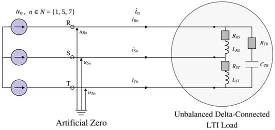
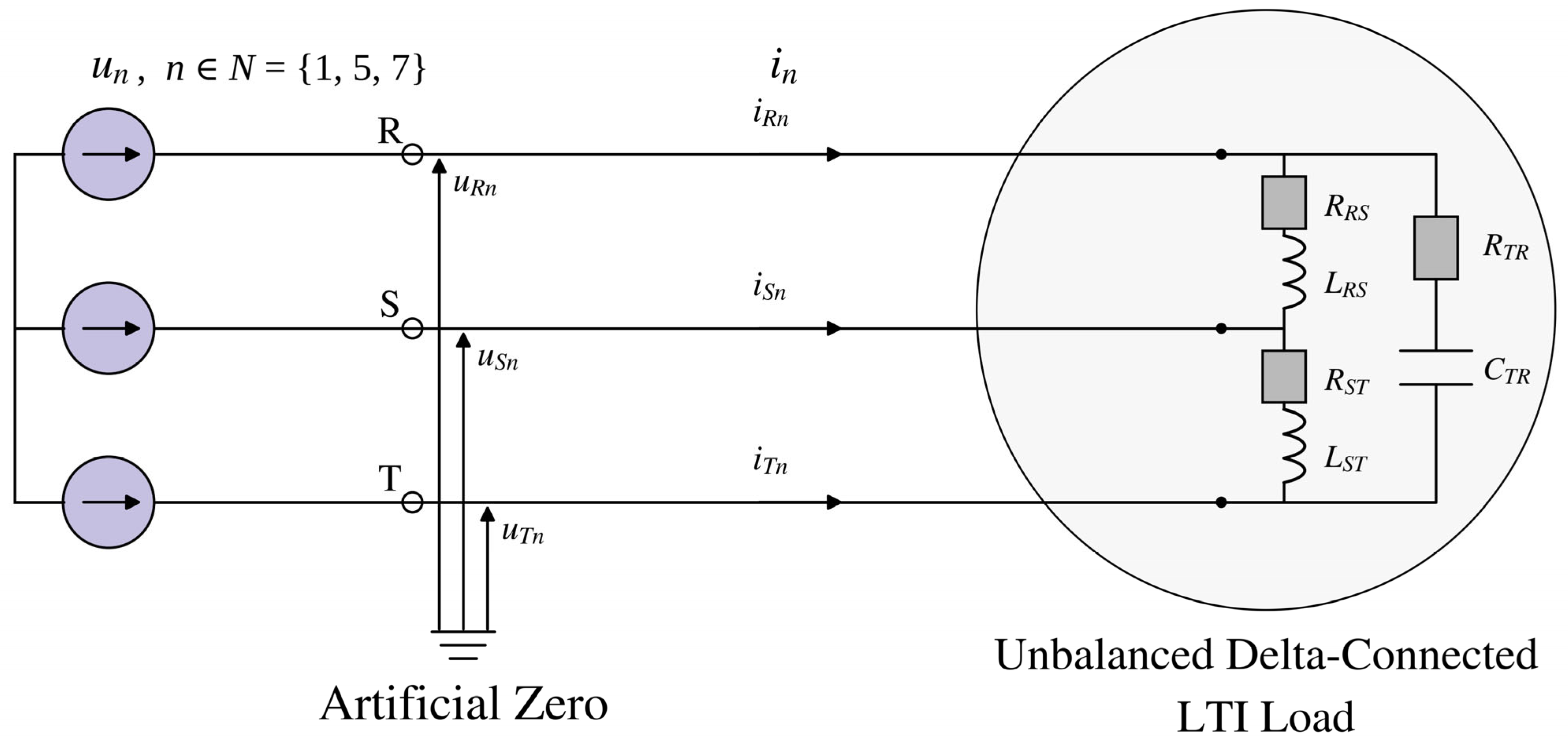
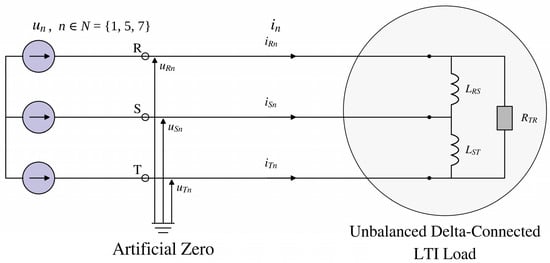
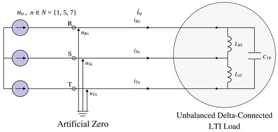
where n denotes the harmonic order, N is the set of harmonic orders present in the supply voltage (in the theoretical illustrations, N = {1, 5, 7}), is the fundamental angular frequency, and and are the vectors of the complex RMS values of the n-th harmonic of the terminal voltages (measured with respect to the artificial zero, Figure 1) and of the line currents, respectively. Hence, Equations (1)–(7) are formulated in the harmonic domain and are not limited to the fundamental frequency.
Figure 1.
Scheme of the three-phase three-wire system considered in Theoretical Illustration 1 (unbalanced RLC load), supplied by a symmetrical nonsinusoidal voltage source (series connection of harmonic sources of orders n ∈ N = {1, 5, 7} in each phase). The arrows denote the reference directions of the line currents and of the voltages measured with respect to the artificial zero.
The total equivalent conductance can be obtained from the active power P balance as follows:
This equivalent conductance gives rise to the active-current component , which is expressed as follows:
Using Equation (3) together with the harmonic-specific equivalent conductances, the scattered-current component can be expressed as follows:
The harmonic-specific equivalent susceptances yield the following expression for the reactive-current component :
For a three-phase three-wire circuit supplied by a symmetrical nonsinusoidal voltage source, the total unbalanced current consists of only one component, namely the negative-sequence unbalanced current. It can therefore be expressed as follows:
For the considered three-phase three-wire load under nonsinusoidal supply conditions, the resultant current can be written as follows:
The three-phase RMS value of the load current is therefore composed of four mutually orthogonal components, and its square equals the sum of their squares:
The corresponding power equation, derived from the orthogonal voltage and current components, can be written as follows:
where the reactive power , the scattered power , and the negative-sequence unbalanced power are each equal to the product of the voltage three-phase RMS value and the three-phase RMS value of the respective current component: , , and ; Equation (10) is obtained by multiplying Equation (9) by . The scattered power results from the variation in the load conductance with harmonic order around the equivalent conductance , whereas the negative-sequence unbalanced power results from load unbalance, described by the unbalanced admittance . The superscript n in and denotes the negative sequence and should not be confused with the harmonic order n.
The component quantities introduced in the preceding equations are defined below. In particular, the unbalanced admittance is given by the following:
whereas the voltage vector associated with load unbalance can be written as follows:
A key quantity in the above formulation is the generalized rotation coefficient , defined as follows:
where s is the sequence indicator of the n-th voltage harmonic: s = 1 for positive-sequence harmonics (n = 3k + 1) and s = −1 for negative-sequence harmonics (n = 3k − 1), k being a natural number.
The power factor is as follows:
Equations (3)–(7), adopted from the CPC theory for 3-p 3-w systems [2,10,15], define the equivalent conductance, active current, scattered current, CPC reactive current, and negative-sequence unbalanced current, respectively. The 3-p 3-w load current therefore contains four mutually orthogonal CPCs. No independent positive-sequence or zero-sequence unbalanced component is present in the adopted formulation.
3. Classical Budeanu Power Theory and Line Currents Obtained from Circuit Laws
In the classical Budeanu approach, active and reactive powers are calculated as the sums of the harmonic active and reactive powers. Distortion power is then defined as the residual part of the apparent power.
According to Budeanu [1], the active power , the reactive power , and the distortion power are defined as follows:
Here, X denotes a phase index from the set {R, S, T}, whereas YY denotes a line-to-line branch index from the set {RS, ST, TR}.
The classical definition provides the value of but does not identify the physically distinct current components constituting this power.
The harmonic branch currents are calculated from Ohm’s law using the line-to-line voltages and the corresponding branch admittances. The line currents are subsequently reconstructed using Kirchhoff’s current law. These currents constitute the reference solution used to validate the CPC and extended Budeanu current decompositions.
The complex RMS values of the branch currents in the delta-connected load are obtained from Ohm’s law. The line currents are then determined from Kirchhoff’s current law:
The complex RMS values of the line currents resulting from the line-to-line currents in the delta-connected system are given by the following:
Finally, the line currents in a three-phase three-wire system can be expressed as follows:
For the three-wire system supplied by a symmetrical nonsinusoidal voltage, the three-phase RMS value of the load current is as follows:
4. Extended Budeanu Power Theory for 3-p 3-w Systems
The formulation presented below is restricted to three-phase three-wire systems. Systems with a neutral conductor, in which zero-sequence currents and triplen harmonics can flow and the unbalanced current contains positive-, negative-, and zero-sequence components, were analyzed for a symmetrical nonsinusoidal supply in [21], where a seven-component decomposition was obtained. A comparison of both formulations is given in Section 6.7.
4.1. Common Elements of the CPC and Budeanu Theories
The active current in the CPC and Budeanu descriptions is the same because active power is common to both theories. Budeanu reactive power defines the equivalent Budeanu susceptance and the corresponding Budeanu reactive current; the same definitions were used for single-phase and four-wire systems in [20,21].
Both theories obtain the active power as the sum of the harmonic active powers, Equation (15); for periodic waveforms, this sum equals the average of the instantaneous power over one period; the same active power determines the equivalent conductance in Equation (3). Consequently, and the active current are common to both theories [5,8,13,20,21]. The reactive quantities differ because is the algebraic sum of harmonic reactive powers of possibly opposite signs, whereas the CPC reactive current depends on the susceptance of each harmonic separately. The scattered and unbalanced currents are not defined in the classical Budeanu theory and are adopted here from the CPC theory without modification.
The equivalent susceptance is defined as follows:
Based on the equivalent susceptance of the complete system , the expression for the Budeanu reactive current can be derived as follows:
Its three-phase RMS value is determined from the following:
The condition under which the reactive currents in the two power theories are equal is given below:
The CPC reactive current and the Budeanu reactive current are equal if and only if the load susceptance is invariant with harmonic order over the harmonic set present in the supply voltage. A sinusoidal supply is a trivial special case because it contains only one voltage harmonic.
4.2. Physical Interpretation of Budeanu Distortion Power
The extended theory retains the active, scattered, and negative-sequence unbalanced currents from the CPC theory. The difference between the CPC reactive current and the Budeanu reactive current is associated with the deviations of the harmonic susceptances from and defines the Budeanu-complemented reactive current, namely:
The three-phase RMS value of this current is as follows:
With the additional component included, the load current in the three-phase three-wire system supplied by a symmetrical nonsinusoidal voltage source is given by the following:
The additional current component is orthogonal to the remaining components (see Appendix A). Therefore, the following expression for the three-phase RMS value of the load current can be written according to the extended Budeanu theory:
The power equation in this case takes the following form:
In three-phase three-wire systems supplied by symmetrical nonsinusoidal voltages, Budeanu distortion power can consist of up to three components, namely:
where is the Budeanu-complemented reactive power, whereas and are defined as in Equation (10). The scattered power results from the conductance variation with harmonic order , the Budeanu-complemented reactive power from the deviation of the harmonic susceptances from the equivalent Budeanu susceptance , and the negative-sequence unbalanced power from load unbalance . Because these components consist of several harmonics of different frequencies, they cannot be represented jointly on a single phasor diagram. Their relation has a geometric interpretation in terms of mutually orthogonal quantities: is the diagonal of a rectangular construction formed by , , and , where the Budeanu distortion current is in turn formed by , , and , so that .
Thus, the load current in the extended Budeanu theory consists of five mutually orthogonal components: active, scattered, Budeanu reactive, Budeanu-complemented reactive, and negative-sequence unbalanced current. The quantities ,, and are expressed in VA, whereas and are expressed in var.
4.3. Use of Generative Artificial Intelligence
Generative AI tools were used for two purposes only: to help prepare the graphical layouts of the circuit schemes of the three theoretical illustrations and to check the English grammar and syntax after translation. All theoretical derivations, numerical calculations, choices of load parameters, analyses, interpretations, and conclusions are the authors’ own work and were verified by them. Every AI-assisted element was checked and edited by the authors, who accept full responsibility for the content of the manuscript.
5. Theoretical Illustrations
The following three theoretical illustrations demonstrate the occurrence of the individual components of Budeanu distortion power. The supply voltage has the same harmonic amplitudes and harmonic content in all illustrations. Harmonics of order n = 3k are not considered for the reasons given below. The supply source is assumed to be ideal (zero internal impedance); hence, the same symmetrical nonsinusoidal voltage is applied in all three illustrations, which differ only in the parameters of the unbalanced load. In Figure 1 (and in the corresponding schemes of Illustrations 2 and 3), the source un in each phase represents the series connection of the harmonic voltage sources of orders n ∈ N = {1, 5, 7}, in accordance with the Fourier-series representation of the periodic supply voltage. The proposed theory is valid for any finite set of harmonics N. The harmonics 1, 5, and 7 were selected because (i) in a symmetrical three-wire system, triplen harmonics are of zero sequence and do not produce line currents; (ii) the fifth and seventh harmonics are the characteristic harmonics of six-pulse power-electronic converters (n = 6k ± 1) and are among the harmonics most commonly found in low-voltage networks [28]; and (iii) this is the minimal set containing both negative-sequence (n = 5) and positive-sequence (n = 1, 7) harmonics. Including higher-order harmonics would only add further terms to the same sums without introducing a new physical phenomenon.
5.1. Theoretical Illustration 1
Theoretical Illustration 1 concerns a 3-p 3-w circuit fed by a symmetrical nonsinusoidal source with the 1st, 5th, and 7th harmonics; the delta-connected LTI load has its branches between lines R–S, S–T, and T–R. This general RLC case is used to check the five-component decomposition and to identify the components of Budeanu distortion power.
Table 1 gives the branch resistances and reactances at the fundamental frequency.
Table 1.
Theoretical Illustration 1: fundamental-frequency parameters of the load branches.
The branch parameters for the n-th harmonic are obtained from the fundamental-frequency values as , , and ; the same rule is applied in all three theoretical illustrations.
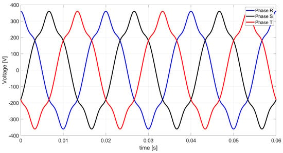
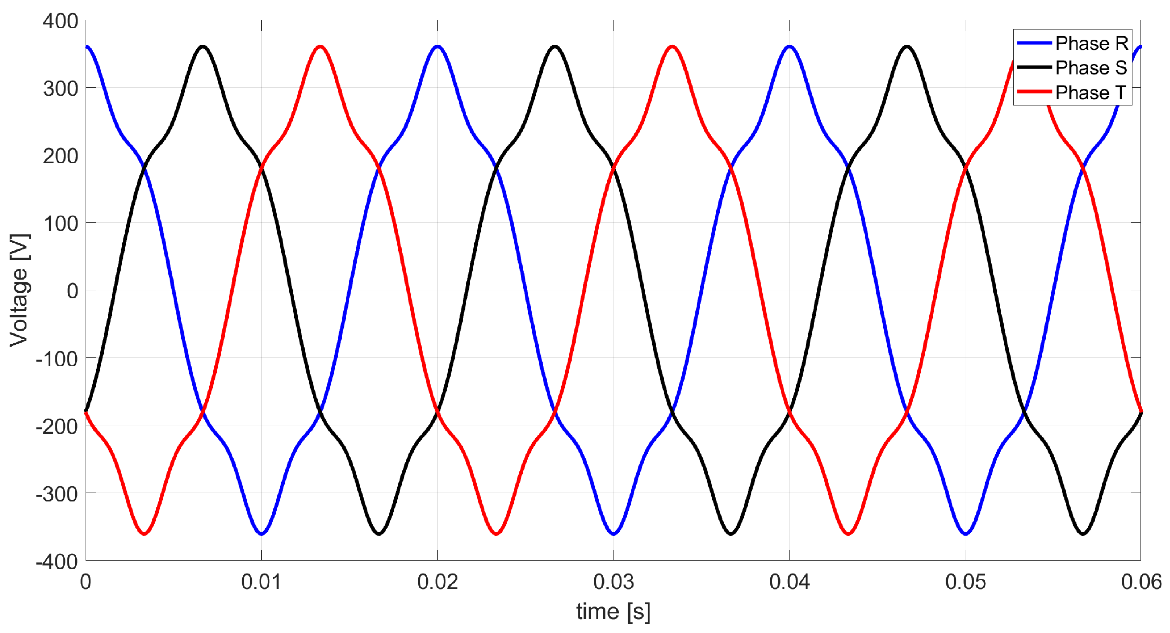
Figure 2 shows the nonsinusoidal source voltages at terminals R, S, and T.
Figure 2.
Nonsinusoidal supply voltages at load terminals R, S, and T.
The supply voltage in Figure 2 has the three-phase RMS value:
Table 2 summarizes the complex harmonic admittances of the three branches of the delta-connected load.
Table 2.
Theoretical Illustration 1: complex branch admittances for harmonics n = 1, 5, 7.
Ohm’s law yields the complex RMS values of the harmonic branch currents, and Kirchhoff’s current law then gives the line currents; both sets of values are collected in Table 3.
Table 3.
Theoretical Illustration 1: complex RMS values of the branch (line-to-line) and line currents for harmonics n = 1, 5, 7.
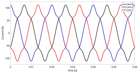
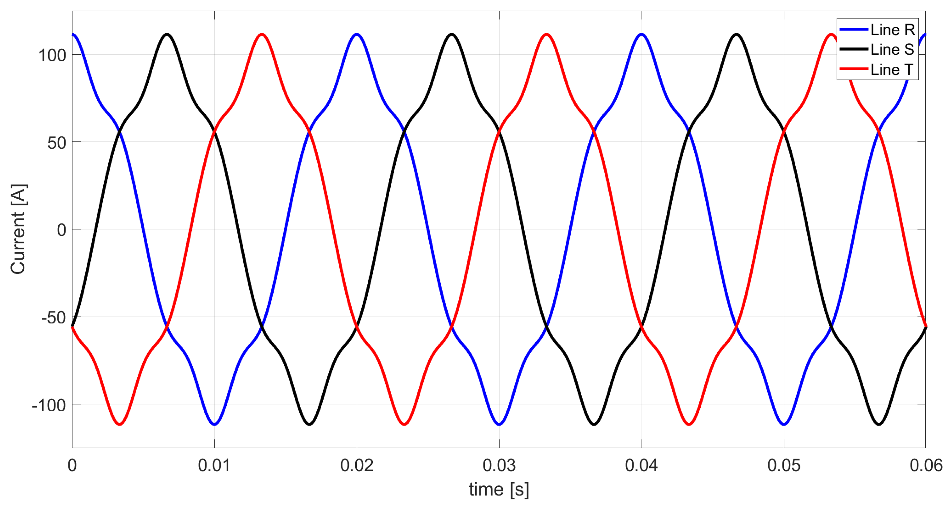
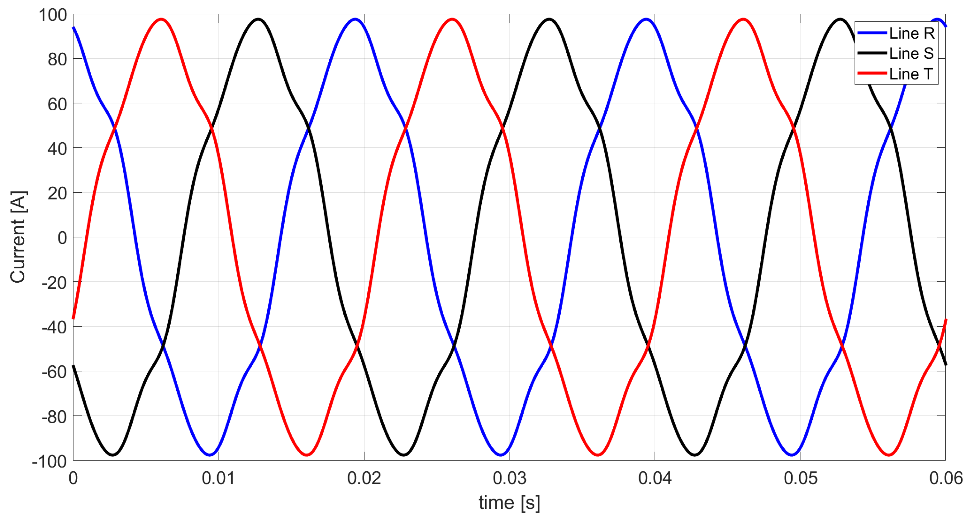
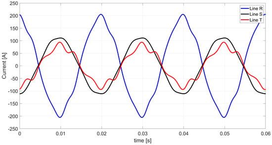
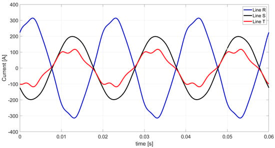
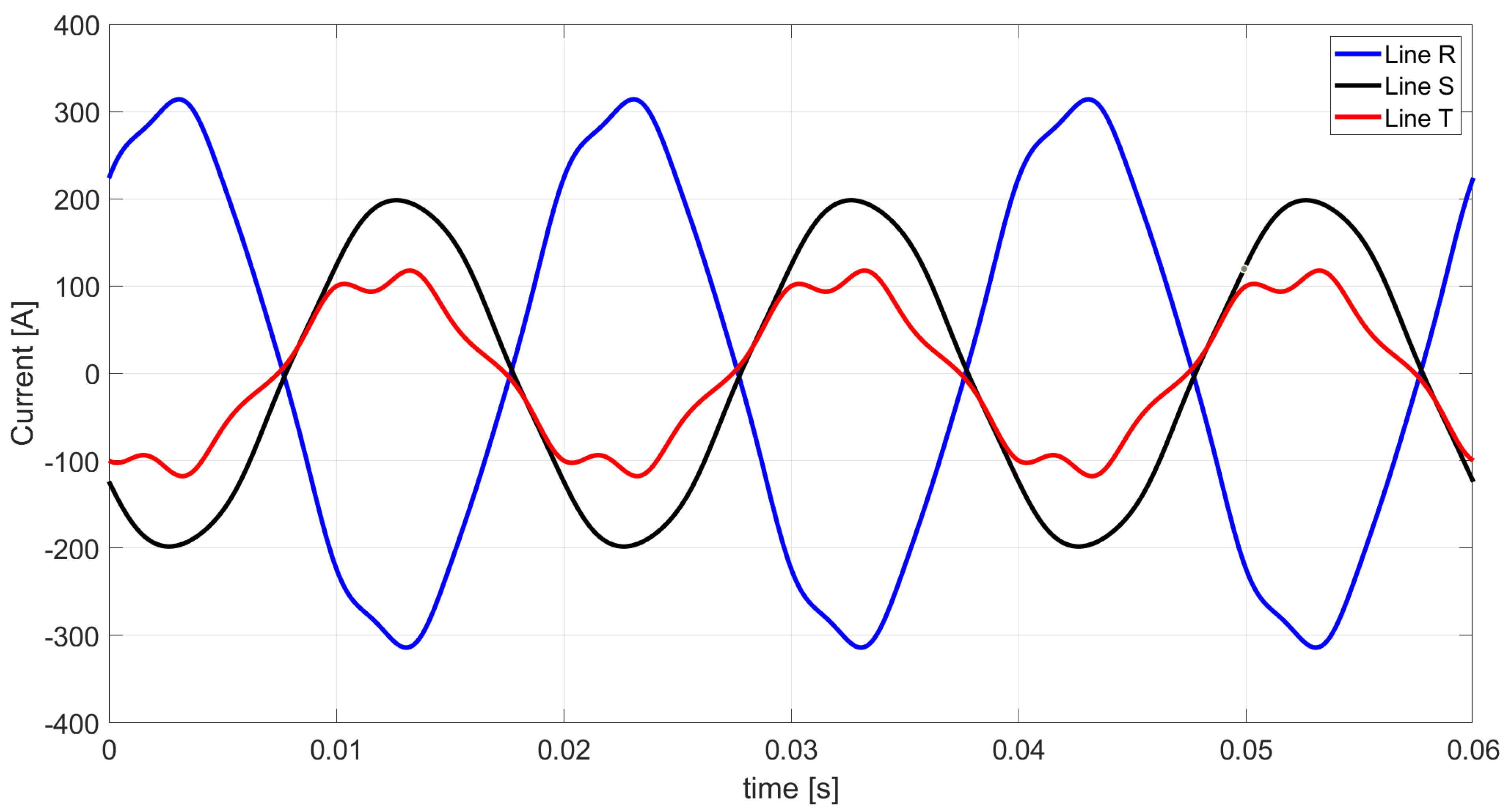
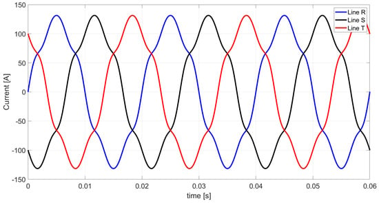
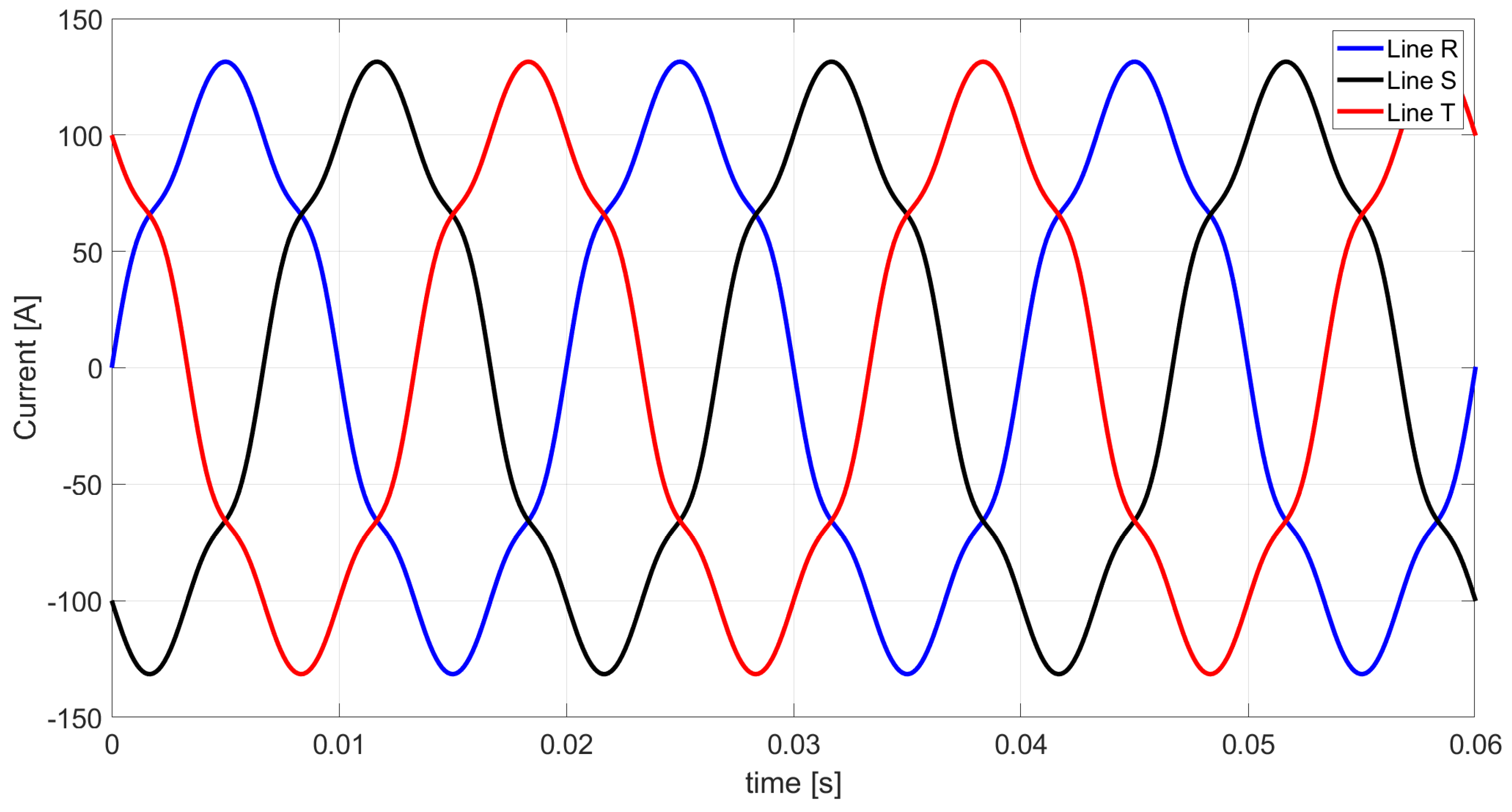
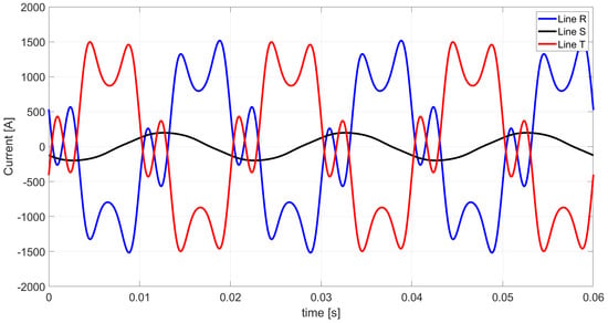
The resulting line-current waveforms obtained from Equations (18)–(20) are shown in Figure 3.
Figure 3.
Theoretical Illustration 1: line currents calculated with Ohm’s law and Kirchhoff’s current law (reference solution).
For the line currents in Figure 3, the three-phase RMS value is as follows:
Using Equations (15) and (16), the active power and Budeanu reactive power were calculated for each considered harmonic. Table 4 lists these values together with their totals for the complete three-phase system.
Table 4.
Theoretical Illustration 1: three-phase active, Budeanu reactive, distortion, and apparent powers.
For Theoretical Illustration 1, Equation (14) gives the following power factor :
From Equation (3), the load in Figure 1 has the equivalent conductance:
The harmonic equivalent conductances and susceptances of the load are given in Table 5; they are defined with respect to line (not line-to-line) quantities.
Table 5.
Theoretical Illustration 1: equivalent conductances and susceptances of the load for harmonics n = 1, 5, 7.
Equation (22) of the extended Budeanu theory gives the equivalent Budeanu susceptance of the load in Figure 1:
The five current components obtained from the extended Budeanu formulation are summarized in Table 6.
Table 6.
Theoretical Illustration 1: three-phase RMS values of the five load-current components in the extended Budeanu theory.
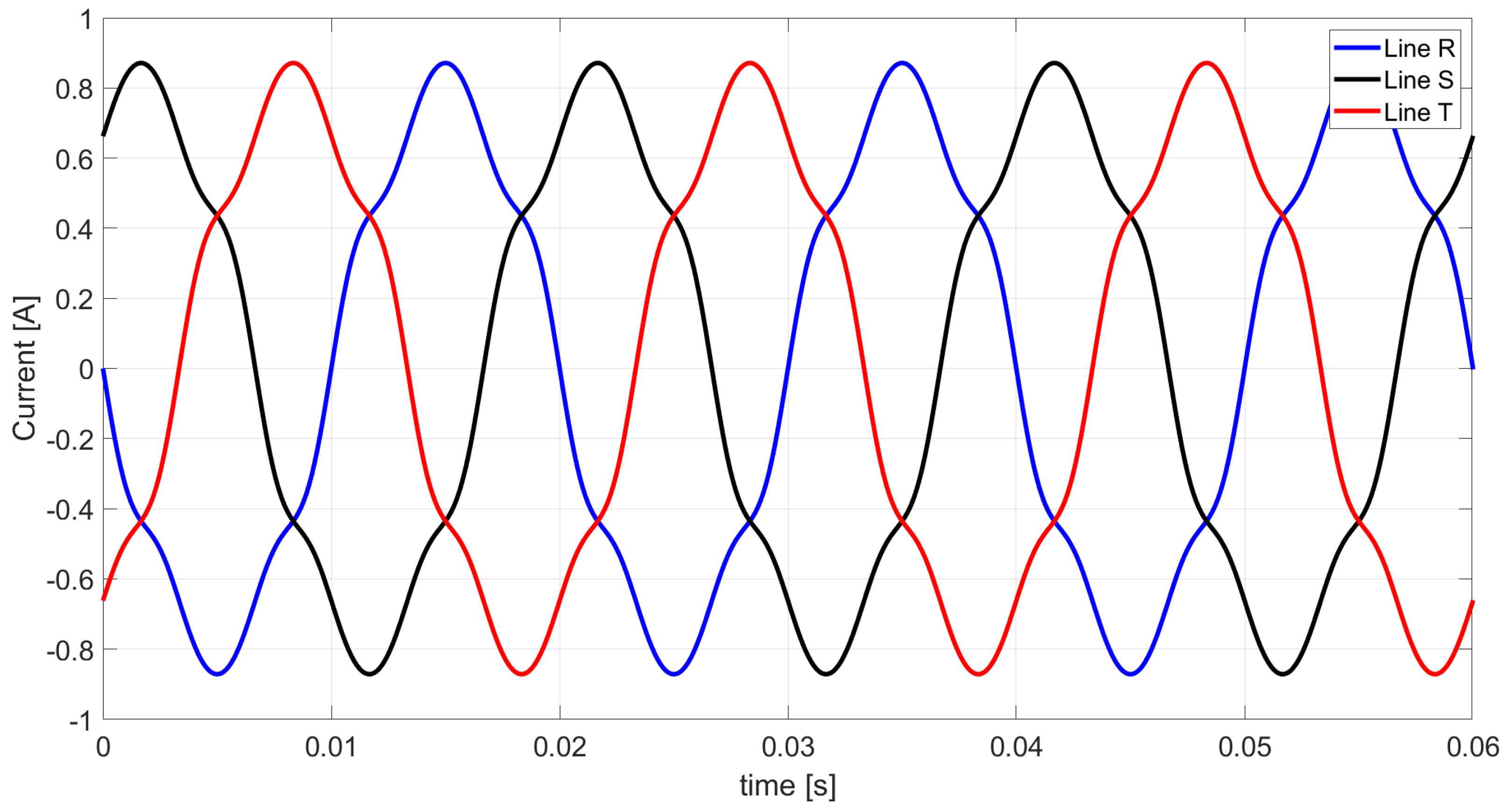
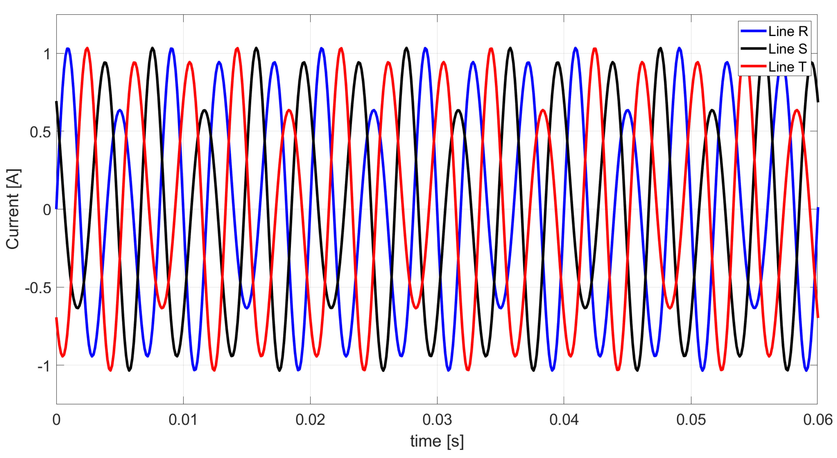
The active, scattered, and negative-sequence unbalanced currents are common to the CPC theory and the extended Budeanu theory. The associated waveforms are shown in Figure 4, Figure 5, Figure 6, Figure 7 and Figure 8. Each waveform represents the time-domain sum of the contributions of all considered harmonics (n = 1, 5, 7) in lines R, S, and T; it does not represent a separate harmonic. The shapes of the scattered current (Figure 5) and of the Budeanu-complemented reactive current (Figure 8) are dominated by the fifth harmonic, for which the RMS values of these components are the largest (Table 6).
Figure 4.
Theoretical Illustration 1: active-current waveforms.
Figure 5.
Theoretical Illustration 1: scattered-current waveforms in lines R, S, and T (time-domain sum of the contributions of harmonics n = 1, 5, and 7).
Figure 6.
Theoretical Illustration 1: negative-sequence unbalanced-current waveforms.
Figure 7.
Theoretical Illustration 1: Budeanu reactive-current waveforms.
Figure 8.
Theoretical Illustration 1: Budeanu-complemented reactive-current waveforms in lines R, S, and T (time-domain sum of the contributions of harmonics n = 1, 5, and 7).
As shown in Figure 9, the sum of the five components specified by Equation (28) reproduces the line-current waveforms of Figure 3.
Figure 9.
Theoretical Illustration 1: line-current waveforms reconstructed from the five orthogonal components.
The reconstructed waveforms coincide with the reference solution in Figure 3, which validates the proposed decomposition for Theoretical Illustration 1. The RMS values of the components of the Budeanu distortion current are listed in Table 7.
Table 7.
Theoretical Illustration 1: three-phase RMS values of the components constituting the Budeanu distortion current.
The tabulated values confirm that the Budeanu distortion current is the orthogonal sum of the scattered current, the Budeanu-complemented reactive current, and the negative-sequence unbalanced current. All three components of the Budeanu distortion current occur in this general RLC case. The negative-sequence unbalanced component is dominant.
5.2. Theoretical Illustration 2
The second example uses the same supply voltage and the same delta connection of the LTI load as Illustration 1, but each branch is either purely resistive or purely reactive, so that the scattered current vanishes. The example verifies the five-component decomposition and shows which components of Budeanu distortion power remain without conductance scattering. The scheme of the circuit is shown in Figure 10.
Figure 10.
Scheme of the three-phase three-wire system considered in Theoretical Illustration 2 (inductive branches RS and ST, resistive branch TR), supplied by a symmetrical nonsinusoidal voltage source (series connection of harmonic sources of orders n ∈ N = {1, 5, 7} in each phase). The arrows denote the reference directions of the line currents and of the voltages measured with respect to the artificial zero.
The fundamental-frequency branch parameters of this load are given in Table 8.
Table 8.
Theoretical Illustration 2: fundamental-frequency parameters of the load branches.
The resulting harmonic admittances of the three branches are listed in Table 9.
Table 9.
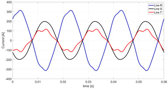
Theoretical Illustration 2: complex branch admittances for harmonics n = 1, 5, 7.
The branch and line currents, calculated in the same way as in Illustration 1, are given in Table 10.
Table 10.
Theoretical Illustration 2: complex RMS values of the branch (line-to-line) and line currents for harmonics n = 1, 5, 7.
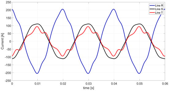
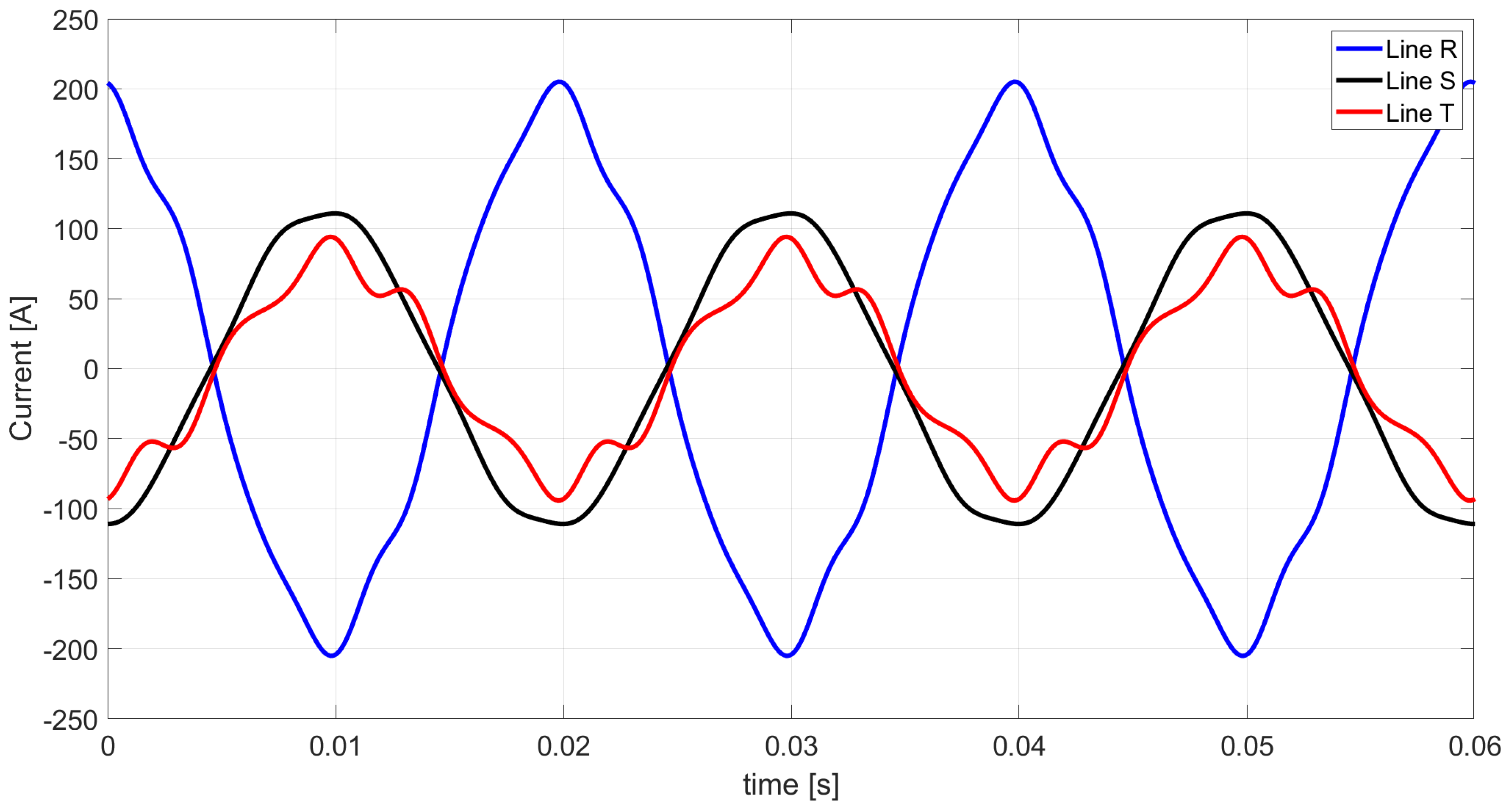
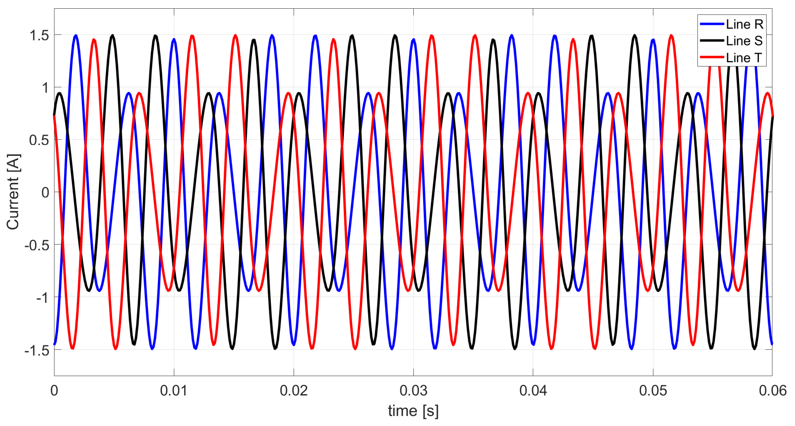
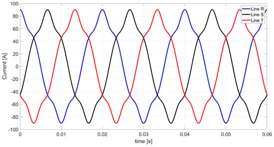
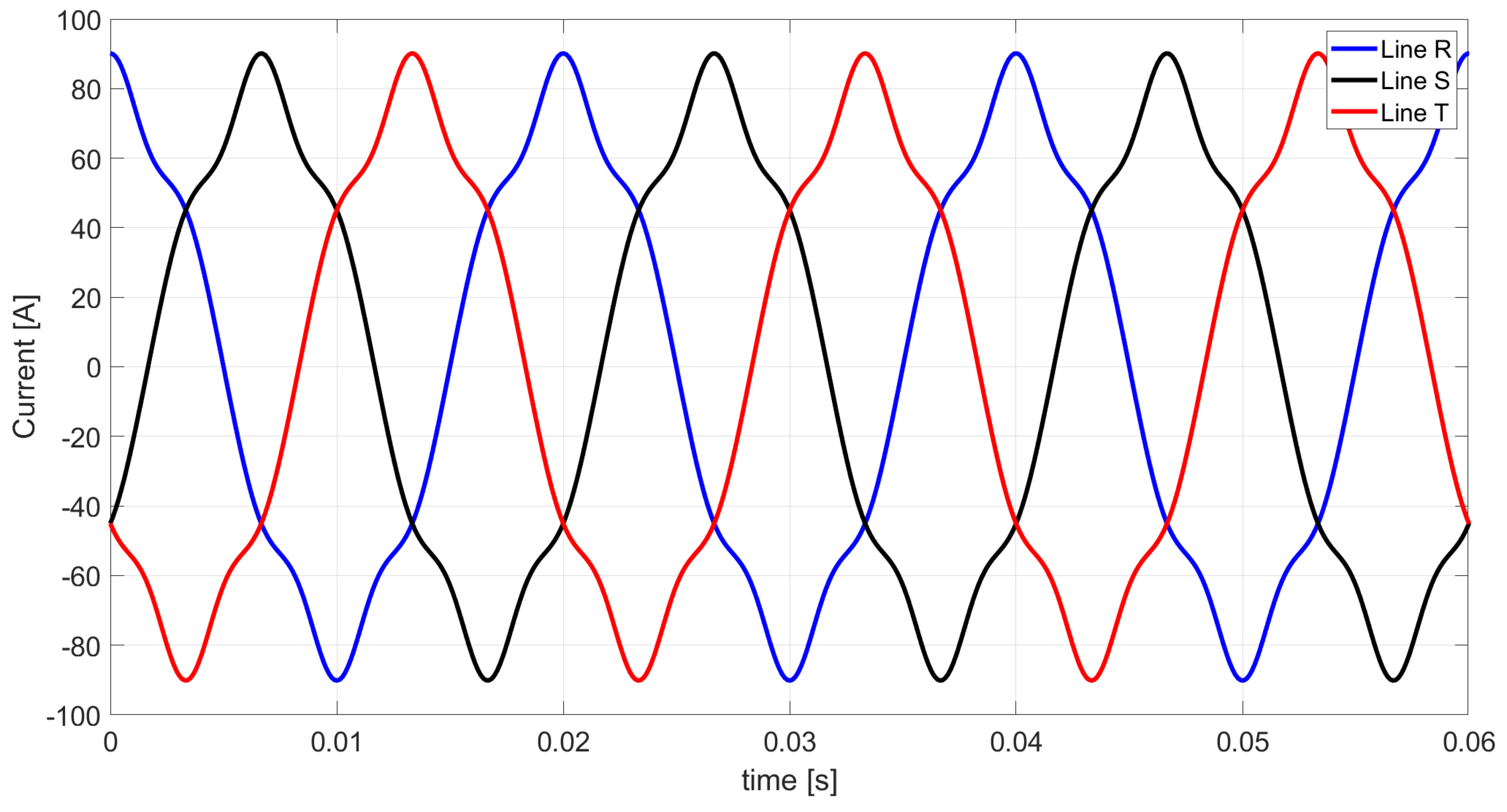
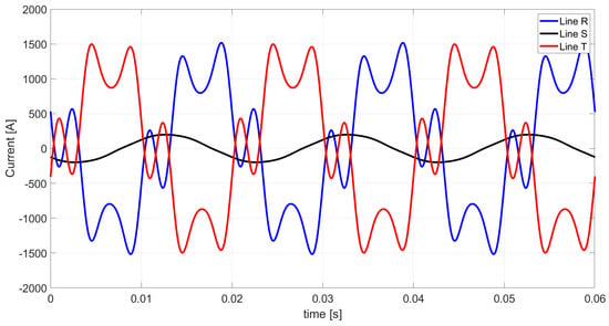
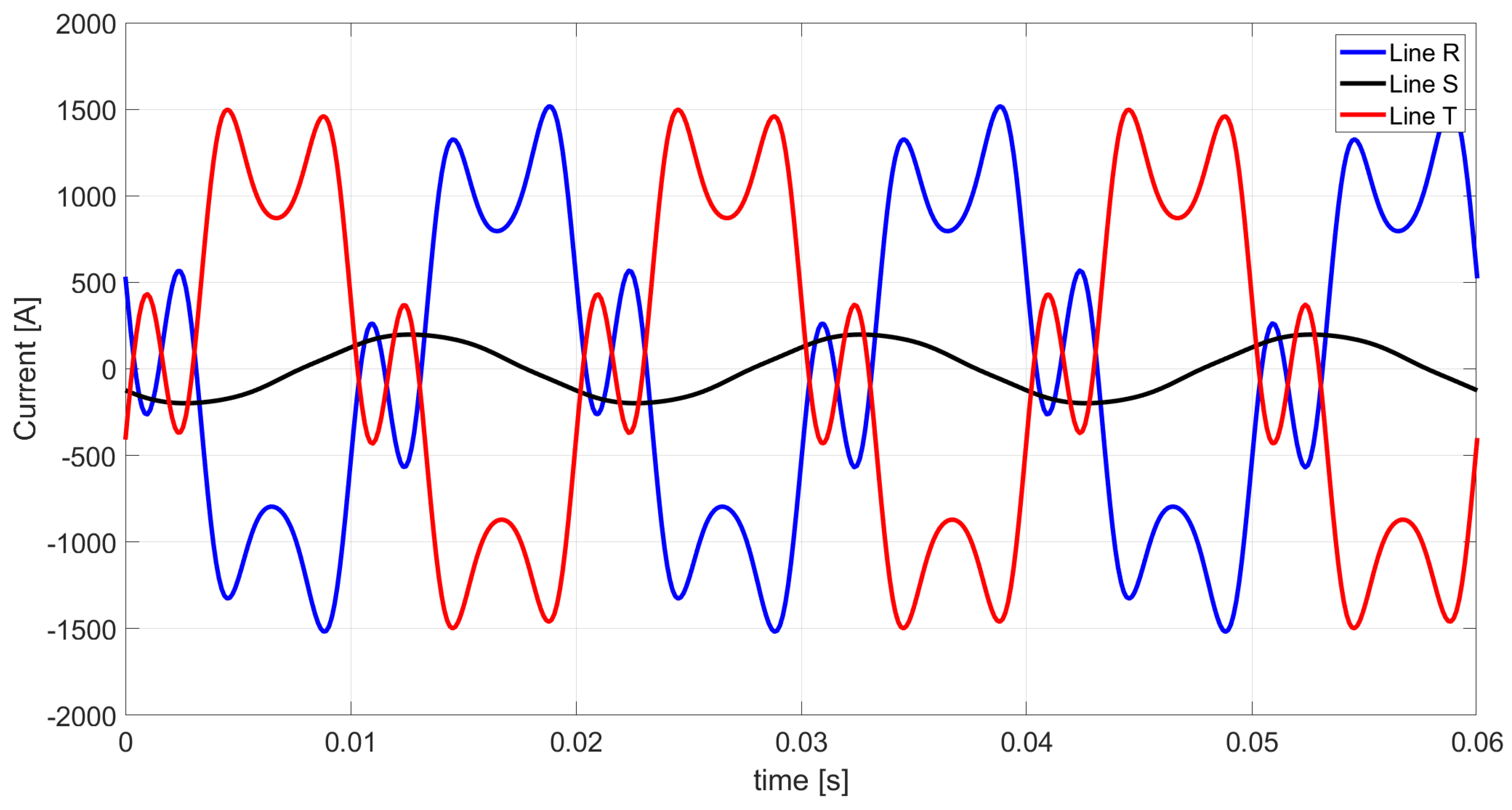
The resulting line-current waveforms obtained from Equations (18)–(20) are shown in Figure 11.
Figure 11.
Theoretical Illustration 2: line currents calculated with Ohm’s law and Kirchhoff’s current law (reference solution).
The three-phase RMS value of the line currents plotted in Figure 11 is as follows:
Using Equations (15) and (16), the active power and Budeanu reactive power were calculated for each considered harmonic. Table 11 lists these values together with their totals for the complete three-phase system.
Table 11.
Theoretical Illustration 2: three-phase active, Budeanu reactive, distortion, and apparent powers.
Applying Equation (14) to Theoretical Illustration 2 yields the power factor :
Equation (3) gives the equivalent conductance of the load in Figure 10:
Table 12 lists the corresponding harmonic equivalent parameters of this load, again referred to line quantities.
Table 12.
Theoretical Illustration 2: equivalent conductances and susceptances of the load for harmonics n = 1, 5, 7.
From Equation (22), the equivalent Budeanu susceptance of the load in Figure 10 is as follows:
The five current components obtained from the extended Budeanu formulation are summarized in Table 13.
Table 13.
Theoretical Illustration 2: three-phase RMS values of the five load-current components in the extended Budeanu theory.
The active, scattered, and negative-sequence unbalanced currents are common to the CPC theory and the extended Budeanu theory. The associated waveforms are shown in Figure 12, Figure 13, Figure 14, Figure 15 and Figure 16.
Figure 12.
Theoretical Illustration 2: active-current waveforms.
Figure 13.
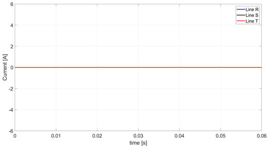
Theoretical Illustration 2: scattered-current waveforms in lines R, S, and T (time-domain sum of the contributions of harmonics n = 1, 5, and 7). The scattered currents in lines R, S, and T are identically zero; therefore, the three curves coincide.
Figure 14.
Theoretical Illustration 2: negative-sequence unbalanced-current waveforms.
Figure 15.
Theoretical Illustration 2: Budeanu reactive-current waveforms.
Figure 16.
Theoretical Illustration 2: Budeanu-complemented reactive-current waveforms in lines R, S, and T (time-domain sum of the contributions of harmonics n = 1, 5, and 7).
As shown in Figure 17, the sum of the five components specified by Equation (28) reproduces the line-current waveforms of Figure 11.
Figure 17.
Theoretical Illustration 2: line-current waveforms reconstructed from the five orthogonal components.
For Theoretical Illustration 2, the reconstructed waveforms are identical to the reference solution in Figure 11, which confirms the decomposition in the absence of the scattered current. The RMS values of the components of the Budeanu distortion current are listed in Table 14.
Table 14.
Theoretical Illustration 2: three-phase RMS values of the components constituting the Budeanu distortion current.
The tabulated values confirm that the Budeanu distortion current is the orthogonal sum of the scattered current, the Budeanu-complemented reactive current, and the negative-sequence unbalanced current. The scattered component is absent. Therefore, Budeanu distortion current consists only of the complemented reactive and negative-sequence unbalanced components.
5.3. Theoretical Illustration 3
In the third example, the supply voltage and the delta connection remain unchanged, whereas the LTI load contains only inductive and capacitive elements. The example verifies the five-component decomposition for a purely reactive load and shows that Budeanu distortion power can occur without active power and without scattered current. The scheme of the circuit is shown in Figure 18.
Figure 18.
Scheme of the three-phase three-wire system considered in Theoretical Illustration 3 (inductive branches RS and ST, capacitive branch TR), supplied by a symmetrical nonsinusoidal voltage source (series connection of harmonic sources of orders n ∈ N = {1, 5, 7} in each phase). The arrows denote the reference directions of the line currents and of the voltages measured with respect to the artificial zero.
The fundamental-frequency reactances of the load branches are listed in Table 15.
Table 15.
Theoretical Illustration 3: fundamental-frequency parameters of the load branches.
Table 16 contains the harmonic admittances of the three reactive branches.
Table 16.
Theoretical Illustration 3: complex branch admittances for harmonics n = 1, 5, 7.
Table 17 contains the branch and line currents, determined with Ohm’s law and Kirchhoff’s current law as before.
Table 17.
Theoretical Illustration 3: complex RMS values of the branch (line-to-line) and line currents for harmonics n = 1, 5, 7.
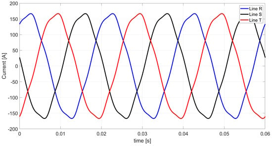
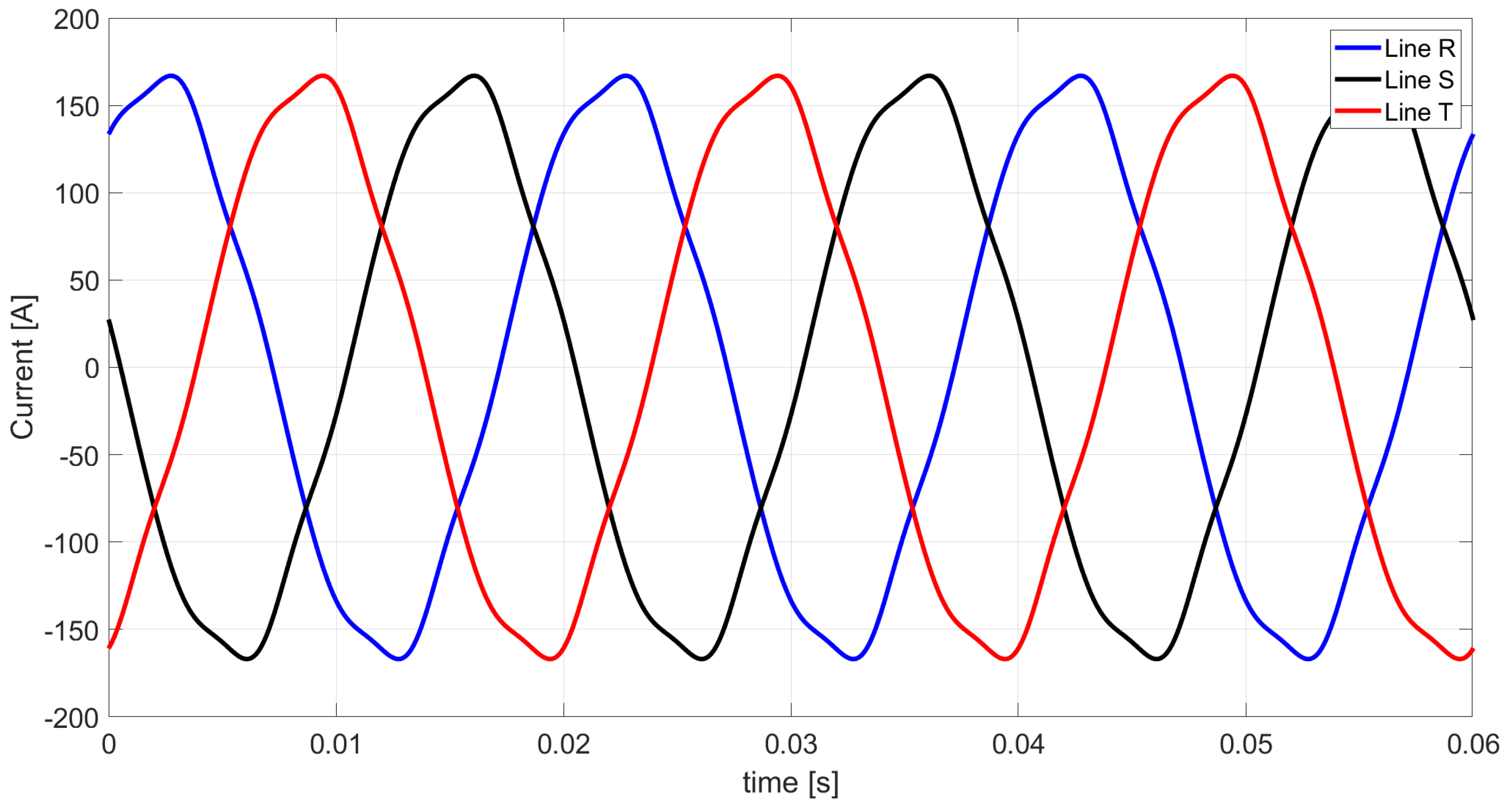
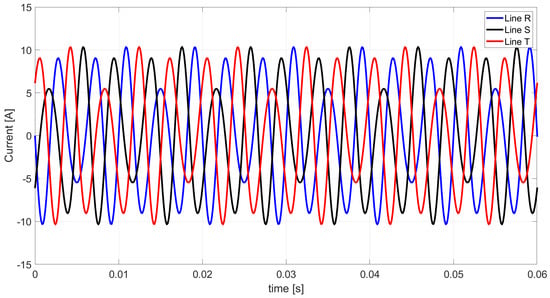
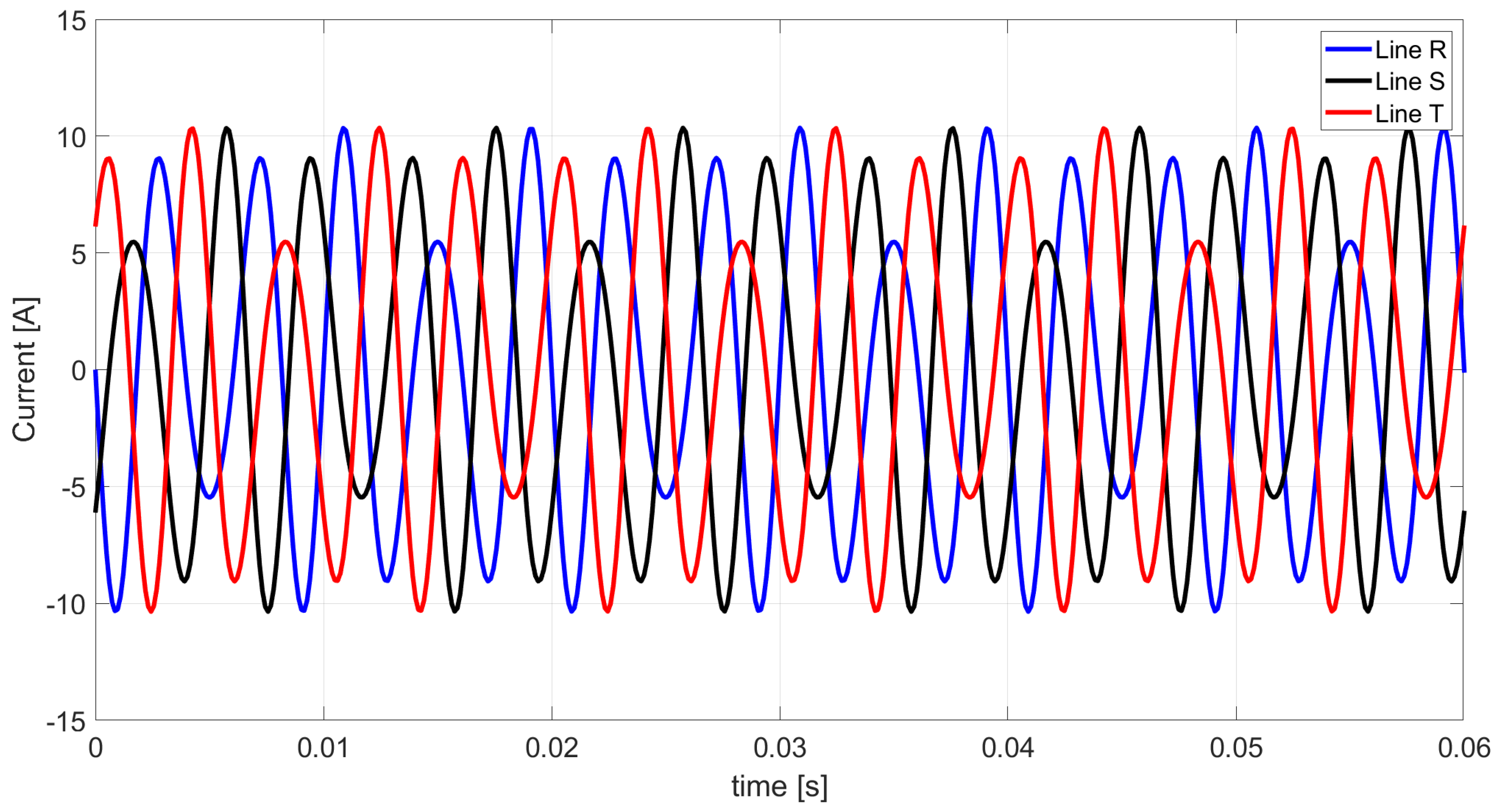
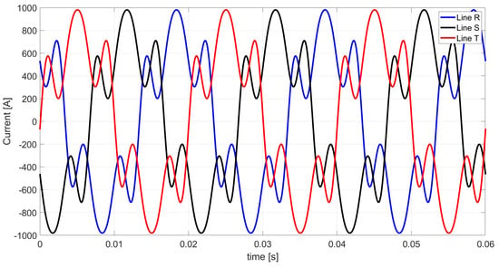
The resulting line-current waveforms obtained from Equations (18)–(20) are shown in Figure 19.
Figure 19.
Theoretical Illustration 3: line currents calculated with Ohm’s law and Kirchhoff’s current law (reference solution).
The line currents in Figure 19 have the three-phase RMS value:
Using Equations (15) and (16), the active power and Budeanu reactive power were calculated for each considered harmonic. Table 18 lists these values together with their totals for the complete three-phase system.
Table 18.
Theoretical Illustration 3: three-phase active, Budeanu reactive, distortion, and apparent powers.
In Theoretical Illustration 3, the power factor obtained from Equation (14) is:
Because the load has no resistive elements, Equation (3) yields a zero equivalent conductance for the load in Figure 18:
For this load, the harmonic equivalent parameters, referred to line quantities, are listed in Table 19.
Table 19.
Theoretical Illustration 3: equivalent conductances and susceptances of the load for harmonics n = 1, 5, 7.
The extended Budeanu theory, Equation (22), yields the following equivalent Budeanu susceptance of the load in Figure 18:
The five current components obtained from the extended Budeanu formulation are summarized in Table 20.
Table 20.
Theoretical Illustration 3: three-phase RMS values of the five load-current components in the extended Budeanu theory.
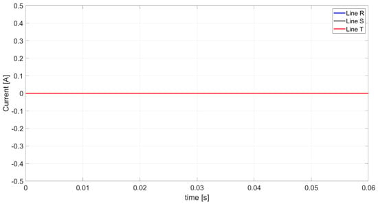
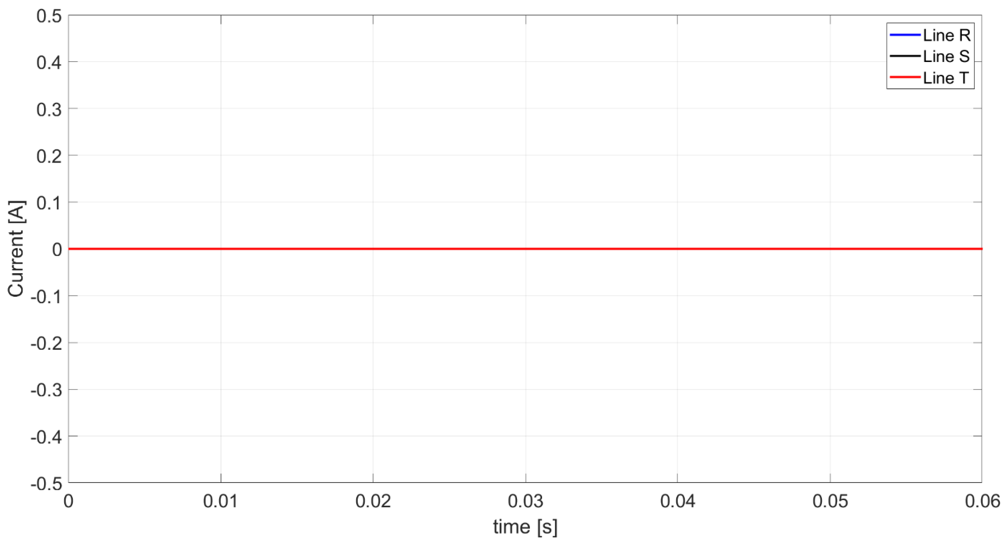
The active, scattered, and negative-sequence unbalanced currents are common to the CPC theory and the extended Budeanu theory. The associated waveforms are shown in Figure 20, Figure 21, Figure 22, Figure 23 and Figure 24.
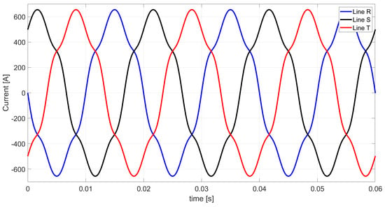
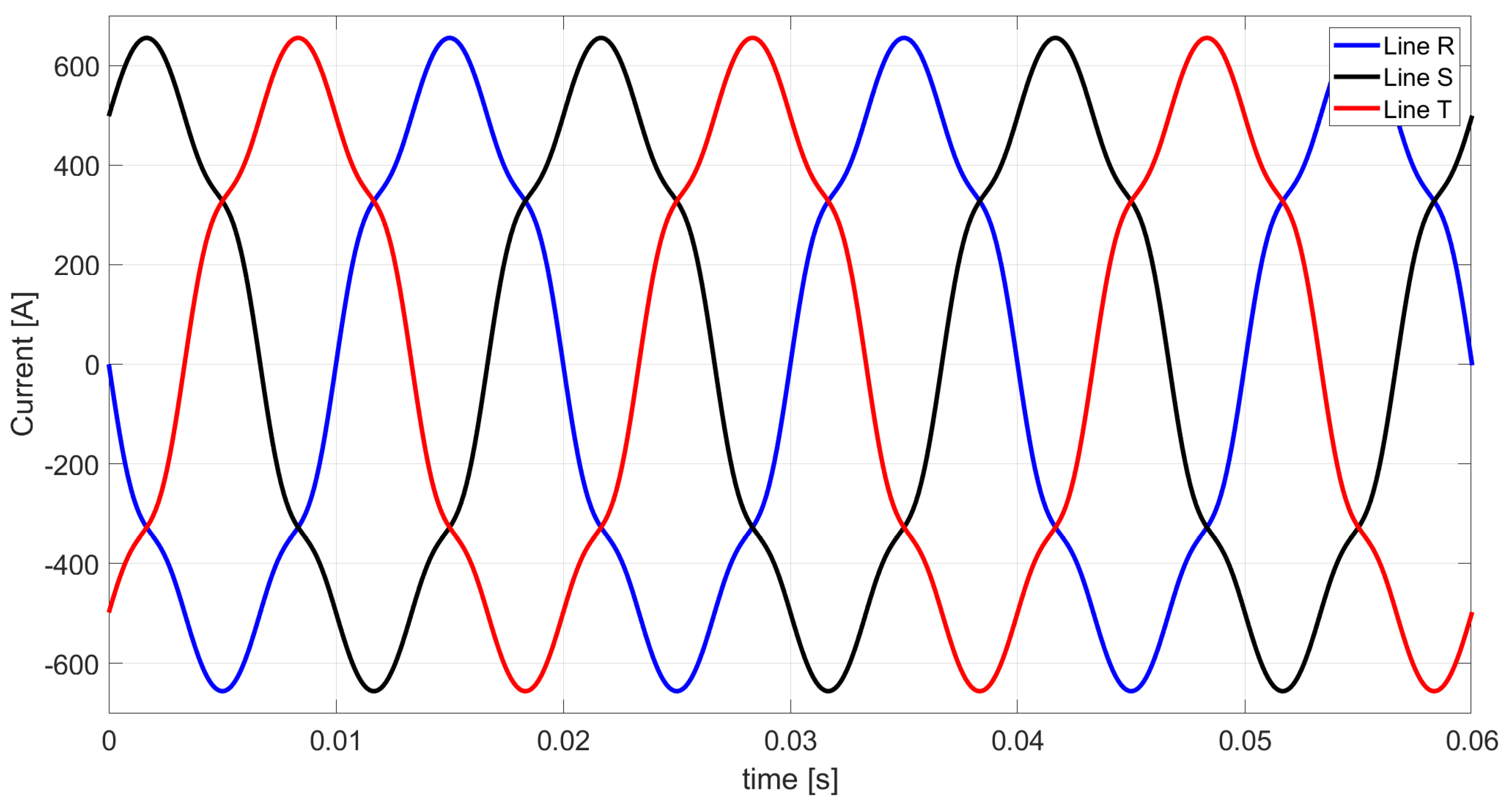
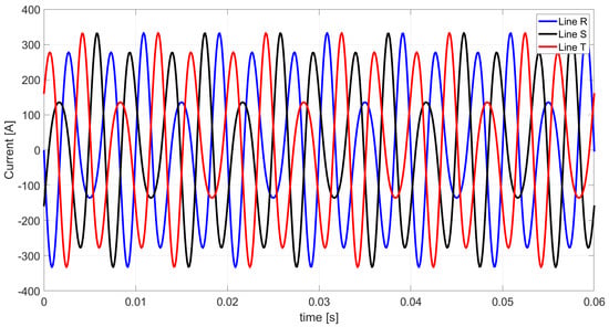
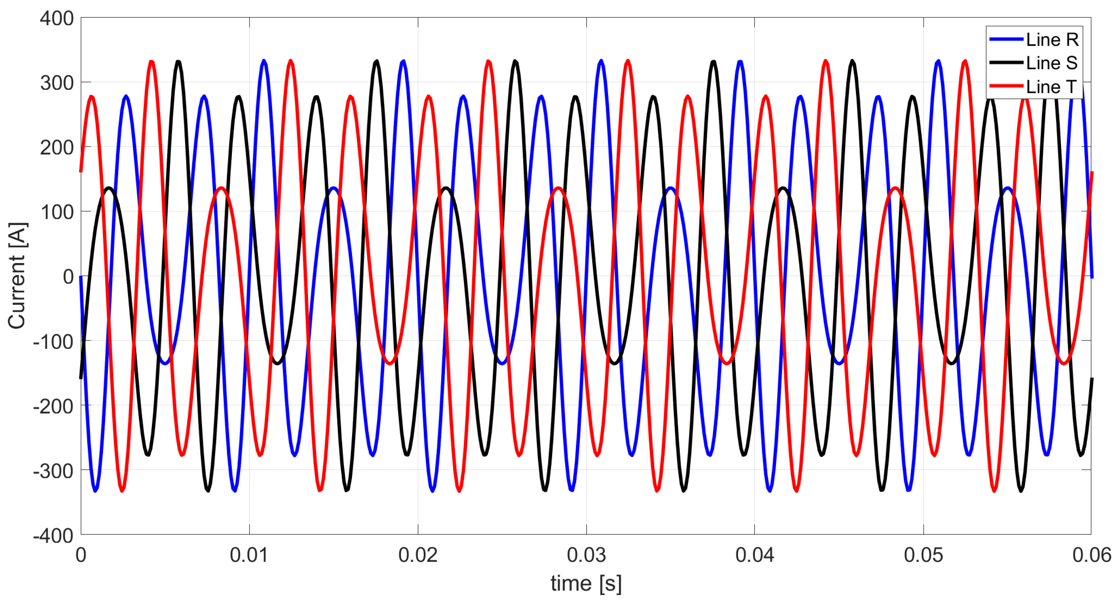
Figure 20.
Theoretical Illustration 3: active-current waveforms. The active currents in lines R, S, and T are identically zero; therefore, the three curves coincide.
Figure 21.
Theoretical Illustration 3: scattered-current waveforms in lines R, S, and T (time-domain sum of the contributions of harmonics n = 1, 5, and 7). The scattered currents in lines R, S, and T are identically zero; therefore, the three curves coincide.
Figure 22.
Theoretical Illustration 3: negative-sequence unbalanced-current waveforms.
Figure 23.
Theoretical Illustration 3: Budeanu reactive-current waveforms.
Figure 24.
Theoretical Illustration 3: Budeanu-complemented reactive-current waveforms in lines R, S, and T (time-domain sum of the contributions of harmonics n = 1, 5, and 7).
As shown in Figure 25, the sum of the five components specified by Equation (28) reproduces the line-current waveforms of Figure 19.
Figure 25.
Theoretical Illustration 3: line-current waveforms reconstructed from the five orthogonal components.
In Theoretical Illustration 3, the reconstructed waveforms likewise coincide with the reference solution in Figure 19, although the active and scattered currents are zero. The RMS values of the components of the Budeanu distortion current are listed in Table 21.
Table 21.
Theoretical Illustration 3: three-phase RMS values of the components constituting the Budeanu distortion current.
The tabulated values confirm that the Budeanu distortion current is the orthogonal sum of the scattered current, the Budeanu-complemented reactive current, and the negative-sequence unbalanced current. The load is purely reactive. The active and scattered currents vanish; nevertheless, the Budeanu distortion current is nonzero owing to the complemented reactive and negative-sequence unbalanced components.
6. Discussion of the Theoretical Illustrations
The three theoretical illustrations confirm that the extended Budeanu theory developed for three-phase three-wire systems provides a physically interpretable decomposition of the load current and, consequently, of Budeanu distortion power. In all considered cases, the line currents reconstructed from the orthogonal current components are identical to the line currents calculated directly from Ohm’s law and Kirchhoff’s current law. This agreement confirms that the proposed current decomposition does not modify the electrical state of the system but only separates the total current into components associated with distinct properties of the load.
The main result of the theoretical analysis is that Budeanu distortion power in a three-phase three-wire system is not an unspecified residual quantity. In the proposed formulation, it is related to the Budeanu distortion current, which consists of the scattered current, the Budeanu-complemented reactive current, and the negative-sequence unbalanced current. Therefore, the power relation identifies the three physical mechanisms responsible for the value of Budeanu distortion power in the considered class of systems. The scattered power is caused by the variation in the equivalent conductance with harmonic order. The Budeanu-complemented reactive power is caused by the variation in susceptance with harmonic order with respect to the equivalent Budeanu susceptance. The negative-sequence unbalanced power is caused by load unbalance in the three-phase three-wire system.
The presented decomposition also explains why the original Budeanu theory cannot identify the physical origin of distortion power. In the classical formulation, the value of is obtained only from the difference between the square of the apparent power and the sum of the squares of the active and Budeanu reactive powers. Consequently, identical or similar values of may result from different combinations of scattered, complemented reactive, and unbalanced components. The extended theory removes this ambiguity by relating each current component and its associated power to the equivalent parameters of the load.
6.1. General Case—Theoretical Illustration 1
The first illustration represents the general case of an unbalanced three-phase three-wire RLC load supplied by a symmetrical nonsinusoidal voltage containing the fundamental, fifth, and seventh harmonics. In this system, all five current components of the extended Budeanu theory are present. The RMS values of the active, scattered, Budeanu reactive, Budeanu-complemented reactive, and negative-sequence unbalanced currents are equal to 123.699 A, 1.556 A, 1.006 A, 1.131 A, and 114.536 A, respectively.
The most important observation is that the negative-sequence unbalanced current is much larger than the scattered current and the Budeanu-complemented reactive current. Consequently, the Budeanu distortion current has an RMS value of 114.552 A and is almost entirely determined by the negative-sequence unbalanced component. The small difference between 114.552 A and 114.536 A follows from the simultaneous presence of the scattered and complemented reactive components.
This case demonstrates that a large value of Budeanu distortion power does not necessarily indicate strong waveform distortion caused by a nonlinear load. The load considered here is an LTI load. The dominant contribution to arises from the asymmetrical structure of the load, which generates a substantial negative-sequence unbalanced current. Thus, the extended theory distinguishes between the effect of harmonic-frequency variation in the load parameters and the effect of load unbalance, even though both effects are included jointly in the classical Budeanu distortion power.
For Theoretical Illustration 1, the active power is 49,475.5 W, the Budeanu reactive power is −402.3 var, the Budeanu distortion power is 45,817.2 VA, and the apparent power is 67,433 VA. The small negative value of indicates that the equivalent Budeanu reactive power has a capacitive character. However, the relatively small absolute value of should not be interpreted as an indication of favorable power conditions, because the negative-sequence unbalanced current remains very large. This observation illustrates the limited diagnostic value of when used alone.
6.2. Case Without Conductance Scattering—Theoretical Illustration 2
The second illustration was selected to eliminate the scattered current. Its RMS value is zero for every considered harmonic and for the complete system. Therefore, the scattered power is also equal to zero. This condition allows the effect of the Budeanu-complemented reactive current and the negative-sequence unbalanced current to be analyzed without the influence of conductance variation.
The RMS values of the Budeanu reactive current, the Budeanu-complemented reactive current, and the negative-sequence unbalanced current are 151.799 A, 10.915 A, and 202.444 A, respectively. The corresponding Budeanu distortion current is 202.738 A. Since = 0, this result verifies that the distortion current is determined by the orthogonal combination of , and .
The presence of = 10.915 A shows that the Budeanu reactive current does not fully represent the current associated with the reactive properties of the load. The missing part is the Budeanu-complemented reactive current, caused by the frequency dependence of the load susceptance. This component is not revealed by the classical Budeanu description, although it contributes to the RMS current and to Budeanu distortion power.
The results also demonstrate that an inductive Budeanu reactive power does not characterize all non-active phenomena in the circuit. In Theoretical Illustration 2, = 60,714.7 var, while = 81,088.8 VA. The distortion power exceeds the Budeanu reactive power, despite the absence of conductance scattering. This is caused primarily by the negative-sequence unbalanced component and, to a lesser extent, by the complemented reactive component. Therefore, compensation designed solely on the basis of would not eliminate the main cause of the non-active current in this particular system.
6.3. Purely Reactive Load—Theoretical Illustration 3
The third illustration is particularly important because it concerns a purely reactive and unbalanced load. Both the active power and the active current are zero. Moreover, the scattered current is absent because no resistive elements are present in the load. Nevertheless, the Budeanu distortion power has a considerable value of 436,401.5 VA, while the apparent power is 531,068.4 VA.
In this case, the Budeanu reactive, Budeanu-complemented reactive, and negative-sequence unbalanced currents have RMS values of 756.644 A, 335.021 A, and 1038.381 A, respectively. The Budeanu distortion current is 1091.089 A. This means that the load current cannot be characterized only by the Budeanu reactive current, even though the load contains exclusively reactive elements.
The value of = 335.021 A arises because the inductive and capacitive susceptances vary with harmonic order and differ from the equivalent Budeanu susceptance. This finding is particularly relevant to the interpretation of Budeanu reactive power. In a circuit supplied by a nonsinusoidal voltage, the algebraic sum of the harmonic reactive powers does not identify all current components associated with reactance. The Budeanu-complemented reactive current identifies the part of the reactive current that is omitted by the original Budeanu formulation but is present in the physical current of the load.
At the same time, the dominant component of the distortion current remains the negative-sequence unbalanced current. The result confirms that a purely reactive three-phase three-wire load can produce a substantial not because of nonlinear distortion, but because of the combined effects of frequency-dependent susceptance and load unbalance. This illustration therefore gives a direct physical explanation for a situation that cannot be interpreted from the original relation alone.
6.4. Comparison of the Three Illustrations
The three illustrations were deliberately selected to demonstrate different combinations of the components constituting the Budeanu distortion current. Their comparison is summarized in Table 22.
Table 22.
Comparison of the RMS values of the current components constituting the Budeanu distortion current.
The first illustration provides the most general verification of the proposed power decomposition, because all three components of Budeanu distortion current are present. The second illustration demonstrates that the scattered component is not necessary for distortion power to occur. The third illustration demonstrates that neither active power nor a resistive part of the load is necessary for a significant value of Budeanu distortion power.
The comparison also shows that the negative-sequence unbalanced component dominates in all three test cases. This result is related to the intentionally unbalanced structure of the analyzed loads. However, the general form of the proposed model does not imply that must be dominant. For a symmetrical load with frequency-dependent conductance or susceptance, the Budeanu distortion current can be formed only by , only by , or by their orthogonal combination. Thus, the proposed decomposition applies to a broader set of systems than the three examples considered here.
Additional numerical examples with other load types would not change the approach or the calculation procedure, because the decomposition is derived analytically for arbitrary LTI branch admittances. The occurrence of each component follows directly from the equivalent load parameters: the active current vanishes if (purely reactive load, Theoretical Illustration 3); the scattered current vanishes if for all n ∈ N (e.g., when each branch is either purely resistive or purely reactive, Theoretical Illustrations 2 and 3); the Budeanu-complemented reactive current vanishes if for all n ∈ N, which is always the case for a sinusoidal supply; and the negative-sequence unbalanced current vanishes if for all n ∈ N, e.g., for a balanced load.
6.5. Symmetrical Purely Reactive Load Under Symmetrical Nonsinusoidal Supply
The considered limiting case clarifies the physical meaning of Budeanu distortion power in a three-phase three-wire system. Let the supply voltages be symmetrical but nonsinusoidal, and let the load be balanced and consist of three identical purely reactive elements. Under these conditions, the phase admittances are identical; therefore, the unbalanced current component is absent. Moreover, because the load has no conductive part, the scattered current associated with variations in conductance among the voltage harmonics is also equal to zero. Consequently, neither load unbalance nor harmonic-dependent conductance contributes to the Budeanu distortion-power balance.
The remaining non-active current component is the Budeanu-complemented reactive current. Hence, for this operating condition, the Budeanu distortion current reduces to a single physical component,
and the corresponding power relation becomes
This result follows directly from the fact that the susceptance of an ideal reactive element is frequency dependent. For an inductor, the susceptance decreases with harmonic order, whereas for a capacitor it increases with harmonic order. Thus, when the voltage contains more than one harmonic, the susceptance associated with the n-th harmonic generally differs from the equivalent susceptance . The resulting mismatch, , produces the complemented reactive current and, consequently, a nonzero value of Budeanu distortion power even though the supply and load remain perfectly symmetrical.
This observation is important because it separates waveform-distortion effects from phase asymmetry. In the present case, a nonzero must not be interpreted as evidence of load unbalance: the system is balanced by construction. Instead, is entirely associated with the harmonic dependence of the reactive load. Therefore, the result provides a transparent benchmark for assessing the decomposition of non-active currents and powers. Any formulation applied to this case should predict zero scattered and unbalanced components, while retaining only the complemented reactive component.
For a sinusoidal supply, this component vanishes because only the fundamental harmonic is present and . Accordingly, = 0 and = 0. The contrast between sinusoidal and nonsinusoidal operation demonstrates that the occurrence of Budeanu distortion power in the examined balanced reactive system is caused by the interaction between voltage harmonics and frequency-dependent susceptance, rather than by an asymmetrical circuit configuration.
6.6. Implications of the Proposed Model
The results of the three theoretical illustrations have implications for both the interpretation of power phenomena and the formulation of future compensation methods. First, the proposed extension directly links Budeanu distortion power with the equivalent load parameters. Unlike the classical Budeanu formulation, in which is obtained solely as a residual quantity from apparent, active, and Budeanu reactive powers, the extended model identifies the physical mechanisms contributing to this quantity. Specifically, the decomposition distinguishes the effects of conductance variation with harmonic order, susceptance variation with harmonic order, and negative-sequence load unbalance.
This distinction is relevant to compensation analysis because the identified current components are associated with different load properties and cannot generally be mitigated by the same compensating device. The Budeanu-complemented reactive current results from deviations of the harmonic susceptances from the equivalent Budeanu susceptance; therefore, it provides a theoretical basis for considering reactive compensation strategies. In contrast, the scattered current is associated with harmonic-order-dependent conductance and cannot, in general, be eliminated by a lossless reactive compensator. The negative-sequence unbalanced current originates from the asymmetrical structure of the load and requires a balancing compensation approach.
Thus, the proposed decomposition may support the selection of a compensation objective by indicating whether the dominant increase in the RMS current and apparent power is associated primarily with reactive properties, conductance scattering, or load unbalance. However, the present theoretical–numerical study does not derive, optimize, or experimentally validate a compensator. The formulation should therefore be regarded as a physical and mathematical basis for future studies on the synthesis, optimization, and evaluation of ideal and minimizing compensation methods for three-phase three-wire systems supplied by symmetrical nonsinusoidal voltages.
6.7. Comparison with the Single-Phase and Three-Phase Four-Wire Formulations
The main differences between the present formulation and the previous extensions of Budeanu’s theory for single-phase systems [20] and three-phase four-wire systems [21] result from the absence of the neutral conductor. In three-phase four-wire systems, zero-sequence currents and 3rd harmonics can flow, and the unbalanced current is decomposed into positive-, negative-, and zero-sequence components; consequently, the extended Budeanu theory contains seven mutually orthogonal current components. In three-phase three-wire systems, the line currents sum to zero, 3rd harmonics of a symmetrical supply voltage do not produce line currents, and the unbalanced current consists of only one component, namely the negative-sequence unbalanced current, described by the unbalanced admittance and the rotation coefficient . Therefore, the decomposition reduces to five components, and Budeanu distortion power consists of at most three components instead of five. The comparison is summarized in Table 23.
Table 23.
Comparison of the extended Budeanu formulations for single-phase, three-phase four-wire, and three-phase three-wire systems.
6.8. Scope and Limitations of the Study
The present study is theoretical–numerical. The proposed decomposition does not change the values of voltages and currents; it changes their physical interpretation. The classical and extended Budeanu theories are evaluated from the same complex RMS values of the voltage and current harmonics and yield identical values of , , , and ; they differ only in that the extended theory identifies the physical components of . The correctness of the decomposition is verified analytically by the orthogonality proof in Appendix A and numerically by the agreement between the reconstructed line currents and those obtained from Ohm’s law and Kirchhoff’s current law in each illustration.
The supply source is assumed to be ideal, with zero internal impedance. Under this assumption, the capacitor in the TR branch of Theoretical Illustration 1 changes only the branch and line currents, and its effect is represented by the harmonic-dependent susceptance . In a real network with a nonzero supply impedance, a capacitor would also modify the voltage harmonics and could lead to resonance; this case, as well as asymmetrical supply voltages, four-wire systems, and time-varying or harmonic-generating loads, is outside the scope of the present model. An experimental verification on a real three-phase three-wire installation, including the influence of measurement uncertainty and supply impedance, will be undertaken in a separate study, after the theoretical description has been completed with respect to its mathematical consistency, ideal compensation, and the minimization of balancing compensation, including the tuning of the compensator branches to minimize the line currents.
7. Conclusions
This work developed an extension of Budeanu’s power theory for three-phase three-wire systems supplied by symmetrical nonsinusoidal voltages and feeding unbalanced linear time-invariant loads. The formulation is built on the elements shared by the classical Budeanu theory and the CPC theory. It allows the current of the considered 3-p 3-w load to be represented by five mutually orthogonal components, i.e., the active, scattered, Budeanu reactive, Budeanu-complemented reactive, and negative-sequence unbalanced currents.
The proposed decomposition retains the active, scattered, and negative-sequence unbalanced current components of the CPC theory, while the CPC reactive current is split into two parts, the Budeanu reactive and the Budeanu-complemented reactive currents. The second of them represents the part of the reactive current resulting from the variation in load susceptance with harmonic order relative to the equivalent Budeanu susceptance. Consequently, the CPC reactive current and the Budeanu reactive current are identical only when the load susceptance is invariant with harmonic order for all harmonics present in the supply voltage. A purely sinusoidal supply constitutes a trivial special case of this condition.
The principal result of the developed theory is the physical interpretation of Budeanu distortion power in three-phase three-wire systems. Instead of treating this quantity exclusively as a residual term obtained from the apparent, active, and Budeanu reactive powers, the proposed model shows that it consists of three mutually orthogonal powers, i.e., the scattered, Budeanu-complemented reactive, and negative-sequence unbalanced powers (Equation (31)).
This relation shows that a nonzero value of can arise from three different physical mechanisms: conductance variation with harmonic order, susceptance variation with harmonic order, and load unbalance. The original Budeanu formulation does not distinguish between these mechanisms.
The three theoretical illustrations confirmed the consistency of the proposed model. In each illustration, the current reconstructed from the five orthogonal components was identical to the line current obtained directly from Ohm’s law and Kirchhoff’s current law. The first illustration represented the general RLC case and demonstrated the simultaneous occurrence of all three components of the Budeanu distortion current. The second illustration showed that Budeanu distortion power may remain nonzero even when the scattered current is absent. The third illustration demonstrated that a purely reactive and unbalanced load may have a substantial Budeanu distortion power despite zero active power and zero scattered current. These results confirm that the distortion power defined by Budeanu does not itself identify a separate phenomenon of waveform distortion.
The extended model provides a theoretical basis for a more detailed assessment of non-active current phenomena in 3-p 3-w systems. In particular, it distinguishes the components associated with the reactive properties of the load from those associated with conductance variation and unbalance. This distinction is important for future studies on compensation, because the Budeanu-complemented reactive current may be influenced by appropriately designed reactive compensators, whereas the negative-sequence unbalanced current requires balancing compensation and the scattered current is not affected by a shunt reactive compensator [10]. Thus, the developed formulation creates a consistent starting point for the synthesis and evaluation of ideal and minimizing compensation methods for three-phase three-wire systems.
The present study is theoretical–numerical. An experimental verification on a real three-phase three-wire installation, including the influence of measurement uncertainty and of the internal impedance of the supply, will be undertaken in a separate study, once the theory has been completed with respect to ideal compensation and the minimization of balancing compensation, including the tuning of the compensator branches to minimize the line currents.
Author Contributions
Conceptualization, Z.S., D.S. and T.P.; methodology, Z.S. and T.P.; software, Z.S.; validation, Z.S. and T.P.; formal analysis, Z.S. and D.S.; investigation, Z.S.; resources, Z.S. and T.P.; data curation, Z.S.; writing—original draft preparation, Z.S. and T.P.; writing—review and editing, Z.S., D.S. and T.P.; visualization, Z.S.; supervision, T.P.; project administration, Z.S.; funding acquisition, Z.S. All authors have read and agreed to the published version of the manuscript.
Funding
This research was funded by Bialystok University of Technology, research project No. WZ/WE-IA/7/2026, financed by a research subsidy provided by the minister responsible for science.
Data Availability Statement
All data generated and analyzed in this study are presented in the article; further information is available from the corresponding author upon request.
Acknowledgments
ChatGPT (GPT-4o, Free plan, web interface, OpenAI, San Francisco, CA, USA; accessed September–October 2026) and Perplexity (Pro plan, Claude Opus 5.5 model, web interface, Perplexity AI, San Francisco, CA, USA; accessed September–October 2026) were used to help prepare the graphical layouts of Figure 1, Figure 10 and Figure 18 and to check grammar and syntax after translation into English. All AI-assisted outputs were reviewed and edited by the authors, who are fully responsible for the published content.
Conflicts of Interest
The authors declare no conflicts of interest.
Nomenclature
| Symbol | Meaning |
| n; N | harmonic order; set of harmonic orders present in the supply voltage (N = {1, 5, 7} in the illustrations) |
| k | natural number used to classify harmonic orders (n = 3k ± 1, n = 6k ± 1) |
| fundamental angular frequency | |
| , | vectors of the terminal voltages (with respect to the artificial zero) and of the line currents |
| , | vectors of the complex RMS values of the n-th harmonic of the voltages and line currents |
| , … | n-th harmonic of the voltage of terminal R with respect to the artificial zero and of the line current R (Figure 1, Figure 10 and Figure 18) |
| , | three-phase RMS values of the voltage and current |
| R, S, T; RS, ST, TR | line conductors (roman letters); branches of the delta-connected load |
| X; YY | phase index from the set {R, S, T}; branch index from the set {RS, ST, TR} |
| , , | complex admittances of the load branches for the n-th harmonic |
| , , | equivalent conductance of the load; equivalent conductance and susceptance for the n-th harmonic |
| equivalent Budeanu susceptance | |
| unbalanced admittance for the n-th harmonic; voltage vector associated with load unbalance, Equation (12) | |
| , s | generalized rotation coefficient; sequence indicator (s = 1 for n = 3k + 1, s = −1 for n = 3k − 1) |
| active, scattered, and CPC reactive currents | |
| Budeanu reactive and Budeanu-complemented reactive currents | |
| negative-sequence unbalanced current (superscript n: negative sequence, not the harmonic order) | |
| Budeanu distortion current | |
| P | active power [W] |
| , , | CPC reactive power; Budeanu reactive power; Budeanu-complemented reactive power [var] |
| , , | Budeanu distortion power; scattered power; negative-sequence unbalanced power [VA] |
| S | apparent power [VA] (italic, as opposed to the line conductor S) |
| power factor | |
| CPC; LTI; 3-p 3-w; 3-p 4-w | Currents’ Physical Components; linear time-invariant; three-phase three-wire; three-phase four-wire |
Appendix A
Two three-phase quantities x and y are orthogonal if their scalar product, defined as in [2,21], vanishes:
When both quantities are expressed through the complex RMS values of their harmonics,
the scalar product becomes the following:
The mutual orthogonality of the CPCs has been proved in [2,15]. Therefore, only the Budeanu reactive and Budeanu-complemented reactive currents have to be checked against the other components; the proof follows the procedure applied to single-phase and four-wire systems in [20,21].
- Budeanu reactive current vs. active current:
- 2.
- Budeanu reactive current vs. scattered current:
- 3.
- Budeanu-complemented reactive current vs. active current:
- 4.
- Budeanu-complemented reactive current vs. scattered current:
- 5.
- Budeanu-complemented reactive current vs. Budeanu reactive current:
- 6.
- Budeanu reactive current vs. negative-sequence unbalanced current:
- 7.
- Budeanu-complemented reactive current vs. negative-sequence unbalanced current:
References
- Budeanu, C.I. Puissances Reactives et Fictives; Institut Romain de l’Energie: Bucharest, Romania, 1927. [Google Scholar]
- Czarnecki, L.S. Moce w Obwodach Elektrycznych z Niesinusoidalnymi Przebiegami Prądów i Napięć; Oficyna Wydawnicza Politechniki Warszawskiej: Warsaw, Poland, 2005. [Google Scholar]
- Nowomiejski, Z. Generalized theory of electric power. Arch. Für Elektrotechnik 1981, 63, 177–182. [Google Scholar] [CrossRef] [Scilit]
- Czarnecki, L.S. What is wrong with the Budeanu concept of reactive and distortion power and why it should be abandoned. IEEE Trans. Instrum. Meas. 1987, 36, 834–837. [Google Scholar] [CrossRef] [Scilit]
- Czarnecki, L.S. Budeanu and Fryze: Two frameworks for interpreting power properties of circuits with nonsinusoidal voltages and currents. Electr. Eng. 1997, 80, 359–367. [Google Scholar] [CrossRef] [Scilit]
- Willems, J.L. Budeanu’s reactive power and related concepts revisited. IEEE Trans. Instrum. Meas. 2011, 60, 1182–1186. [Google Scholar] [CrossRef] [Scilit]
- Czarnecki, L.S. Budeanu’s Power Theory Misconceptions. In Powers and Compensation in Circuits with Nonsinusoidal Current; Oxford University Press: Oxford, UK, 2025; pp. 669–680. [Google Scholar]
- Czarnecki, L.S. Currents’ Physical Components (CPC)-Based Power Theory. Part I: Power properties of electrical circuits and systems. Przegląd Elektrotechniczny 2019, 95, 1–11. [Google Scholar]
- Czarnecki, L.S. Currents’ Physical Components (CPC)-Based Power Theory. Part II: Filters and reactive, switching and hybrid compensators. Przegląd Elektrotechniczny 2020, 96, 1–11. [Google Scholar] [CrossRef] [Scilit]
- Czarnecki, L.S. CPC in Three-Phase Three-Wire Circuits. In Powers and Compensation in Circuits with Nonsinusoidal Current; Oxford University Press: Oxford, UK, 2025; pp. 269–346. [Google Scholar]
- Czarnecki, L.S. Deficiencies of the Kusters and Moore’s Power Theory. In Powers and Compensation in Circuits with Nonsinusoidal Current; Oxford University Press: Oxford, UK, 2025. [Google Scholar]
- Jeltsema, D. Budeanu’s Concept of Reactive and Distortion Power Revisited. Przegląd Elektrotechniczny 2016, 92, 68–73. [Google Scholar] [CrossRef] [Scilit]
- Czarnecki, L.S. Currents’ Physical Components (CPC) in Circuits with Nonsinusoidal Voltages and Currents. Part 1: Single-Phase Linear Circuits. Electr. Power Qual. Util. J. 2005, 11, 3–14. [Google Scholar]
- Vah, S.; Staud, N. Comparison and extension of advanced frequency domain non-active power decompositions. Electr. Power Syst. Res. 2023, 224, 109654. [Google Scholar] [CrossRef] [Scilit]
- Czarnecki, L.S. Currents’ Physical Components (CPC) in Circuits with Nonsinusoidal Voltages and Currents. Part 2: Three-Phase Three-Wire Linear Circuits. Electr. Power Qual. Util. J. 2006, 12, 3–13. [Google Scholar]
- Czarnecki, L.S.; Haley, P.M. Unbalanced Power in Four-Wire Systems and Its Reactive Compensation. IEEE Trans. Power Deliv. 2015, 30, 53–63. [Google Scholar] [CrossRef] [Scilit]
- Czarnecki, L.S.; Haley, P.M. Power Properties of Four-Wire Systems at Nonsinusoidal Supply Voltage. IEEE Trans. Power Deliv. 2016, 31, 513–521. [Google Scholar] [CrossRef] [Scilit]
- Czarnecki, L.S. Comparison of instantaneous reactive power p-q theory with theory of the currents’ physical components. Electr. Eng. 2003, 85, 21–28. [Google Scholar] [CrossRef] [Scilit]
- Czarnecki, L.S. On some misinterpretations of the instantaneous reactive power p-q theory. IEEE Trans. Power Electron. 2004, 19, 828–836. [Google Scholar] [CrossRef]
- Sołjan, Z.; Zajkowski, M. Extension and correction of Budeanu power theory based on Currents’ Physical Components CPC theory for single-phase systems. Energies 2022, 15, 8321. [Google Scholar] [CrossRef] [Scilit]
- Sołjan, Z.; Popławski, T. Budeanu’s distortion power components based on CPC theory in three-phase four-wire systems supplied by symmetrical nonsinusoidal voltage waveforms. Energies 2024, 17, 1043. [Google Scholar] [CrossRef] [Scilit]
- Albu, H.; Beu, D.; Ciugudeanu, C. Study on the Power Quality of LED Street Luminaires. Sustainability 2022, 14, 9671. [Google Scholar] [CrossRef] [Scilit]
- Djuretic, A.; Skerovic, V.; Arsic, N.; Kostic, M. Luminous Flux to Input Power Ratio, Power Factor and Harmonics When Dimming High-Pressure Sodium and LED Luminaires Used in Road Lighting. Light. Res. Technol. 2019, 51, 304–323. [Google Scholar] [CrossRef] [Scilit]
- Lerch, T.; Rad, M.; Wojnicki, I. Impact of Dimming LED Street Luminaires on Power Quality. Int. J. Electron. Telecommun. 2021, 67, 255–260. [Google Scholar] [CrossRef] [Scilit]
- Gil-de-Castro, A.; Moreno-Munoz, A.; Larsson, A.; de la Rosa, J.J.G.; Bollen, M.H.J. LED street lighting: A power quality comparison among street light technologies. Light. Res. Technol. 2013, 45, 710–728. [Google Scholar] [CrossRef] [Scilit]
- Drgona, P.; Durana, P.; Betko, T. Research of the Negative Influence of Dimmed LED Luminaires in Context of Smart Installations. Sustainability 2021, 13, 9753. [Google Scholar] [CrossRef] [Scilit]
- McLorn, G.; Laverty, D.; Morrow, D.J.; McLoone, S. Load and harmonic distortion characterization of modern low-energy lighting under applied voltage variation. Electr. Power Syst. Res. 2019, 169, 124–138. [Google Scholar] [CrossRef] [Scilit]
- da Silva, R.P.B.; Quadros, R.; Shaker, H.R.; da Silva, L.C.P. Analysis of the Electrical Quantities Measured by Revenue Meters Under Different Voltage Distortions and the Influences on the Electrical Energy Billing. Energies 2019, 12, 4757. [Google Scholar] [CrossRef] [Scilit]
- Hermoso-Orzáez, M.J.; Gago-Calderón, A.; Rojas-Sola, J.I. Power Quality and Energy Efficiency in the Pre-Evaluation of an Outdoor Lighting Renewal with Light-Emitting Diode Technology: Experimental Study and Amortization Analysis. Energies 2017, 10, 836. [Google Scholar] [CrossRef] [Scilit]
- Kurkowski, M.; Popławski, T.; Zajkowski, M.; Sołjan, Z. The Impact of Limiting Reactive Power Flows on Active Power Losses in Lighting Installations. Energies 2024, 17, 4072. [Google Scholar] [CrossRef] [Scilit]
- Popławski, T.; Kurkowski, M. Audit of Road Lighting Installation as a Tool to Improve Energy Intensity—Case Study. Przegląd Elektrotechniczny 2023, 99, 241–244. [Google Scholar] [CrossRef] [Scilit]

Disclaimer/Publisher’s Note: The statements, opinions and data contained in all publications are solely those of the individual author(s) and contributor(s) and not of MDPI and/or the editor(s). MDPI and/or the editor(s) disclaim responsibility for any injury to people or property resulting from any ideas, methods, instructions or products referred to in the content. |
© 2026 by the authors. Licensee MDPI, Basel, Switzerland. This article is an open access article distributed under the terms and conditions of the Creative Commons Attribution (CC BY) license.