


Abstract
The modular multilevel converter (MMC) is currently the mainstream solution for connecting offshore wind power to high-voltage direct-current (HVDC) grids. However, its large number of submodules and bulky energy-storage capacitors have become key bottlenecks that limit the compactness and cost reduction of offshore converter platforms. To achieve a compact offshore converter station, this paper proposes a novel MMDTC-MMC hybrid DC transmission system for offshore wind power. A modular multilevel DC-link T-type converter (MMDTC) is used at the sending end. While effectively overcoming the volume disadvantage of conventional MMCs, the proposed converter retains the inherent advantages of a fully controlled topology, including bidirectional power transmission and black start capability. Considering the physical characteristic that the AC- and DC-side voltages of this topology are directly coupled, a steady-state analytical model of the system is derived. A coordinated control strategy based on an adaptive closed loop for submodule capacitor voltage is then proposed to solve the transient energy-balancing problem caused by strong active- and reactive-power coupling. Quantitative analysis shows that, under the same DC-voltage level and operating conditions, the total number of submodules required by the sending-end MMDTC is only 35.6% of that required by a conventional MMC, while the required capacitance is reduced to 33.41%. With a reasonable sacrifice in device current stress, the hardware cost and physical space required by the offshore converter platform are significantly reduced. Finally, MATLAB/Matlab of R2024a simulation results verify the effectiveness of the proposed compact topology and adaptive control strategy under high-quality steady-state bidirectional power transmission and transient power-step conditions.
1. Introduction
To combat global climate change and achieve the ambitious goals of carbon neutrality, the rapid transition from fossil fuels to renewable energy sources has become a critical global consensus. In this context, offshore wind power has emerged as an indispensable pillar of the future global energy matrix due to its massive theoretical potential, stable wind speeds, high energy utilization rates, and minimal occupation of terrestrial resources [1]. Driven by the urgent global demand for clean energy, offshore wind farms are currently experiencing a rapid and inevitable expansion from near-shore, shallow waters toward far-sea, deep-water regions with much larger generation capacities. However, this large-scale, deep-sea energy exploitation presents unprecedented technical and economic challenges for power transmission. Conventional high-voltage alternating current (HVAC) transmission is severely constrained in transmission distance and capacity by the charging effect of submarine cables and relatively high line losses [2,3,4]. Consequently, high-voltage direct current (HVDC) transmission, which is immune to synchronous operation constraints and cable-charging reactive-power limitations, has become the essential and often the only viable solution for integrating large-capacity offshore wind power over long distances [5,6,7].
At present, the main converter topologies used in offshore-wind-power DC transmission systems include the line-commutated converter (LCC), diode rectifier unit (DRU), and modular multilevel converter (MMC). LCC-based DC transmission systems offer mature technology and large capacity, but they have an inherent risk of commutation failure and require bulky reactive-power compensation equipment and AC filters on the AC side, increasing the volume and construction cost of offshore platforms [8]. To reduce platform volume, the DRU-MMC hybrid DC transmission system, which uses a DRU as the offshore sending-end converter, has been developed [9,10]. The DRU is simple, compact, and highly reliable. However, because diodes conduct in only one direction, the system can transmit power only in one direction and cannot provide black-start support for an offshore wind farm. In addition, DRU operation injects substantial low-order harmonics into the AC side and degrades power quality [11,12,13]. In comparison, an MMC based on fully controllable devices provides high-quality multilevel output voltage waveforms, requires no bulky high-capacity filters, independently controls active and reactive power, and supports black start. It is therefore regarded as one of the most promising technologies for offshore-wind-power integration [14,15,16].
Although MMCs exhibit excellent electrical performance in offshore-wind-power integration, their inherent structural characteristics also create serious engineering challenges. To achieve high-voltage DC transmission, each MMC arm must cascade a large number of half-bridge or full-bridge submodules [17,18,19]. More seriously, because the arm current contains both fundamental-frequency and DC components, the submodule capacitors experience large low-frequency energy fluctuations. Large energy-storage capacitors are therefore required to maintain voltage stability. For offshore converter platforms with limited space and load-bearing capacity, the large number of submodules and bulky capacitors directly result in large converter stations and high costs [20,21,22,23,24]. Thus, a key technical challenge in HVDC transmission is to substantially reduce the number of converter devices and capacitor values while retaining the superior performance of fully controlled converters, thereby making offshore converter platforms compact.
To address these challenges, this paper proposes a novel MMDTC-MMC hybrid DC transmission system for offshore wind power. A modular multilevel DC-link T-type converter (MMDTC) [25,26,27,28] is used at the offshore sending end, while a conventional MMC is used at the onshore receiving end. The topology retains the advantages of fully controlled converters, including bidirectional power transmission, independent reactive-power control, and black-start capability, while substantially reducing the physical volume and investment cost of the offshore converter station.
It should be noted that while our previous studies have successfully explored the basic operational mechanisms of the MMDTC topology in applications, such as STATCOM, power electronic transformer, and Battery energy storage system [24,25,26,27,28], those applications primarily focus on isolated operation scenarios. Applying the MMDTC to high-power bidirectional HVDC transmission introduces fundamentally new physical constraints and system-level challenges. The primary purpose of this study is to formulate a compact and cost-effective hybrid HVDC transmission solution for offshore wind power that significantly reduces the required number of submodules and physical capacitance while fully preserving the superior electrical performance of fully-controlled converters. To achieve this overarching goal, the specific tasks implemented in this study are progressively structured as follows: (1) designing the system topology and operating principles of the MMDTC-MMC hybrid architecture; (2) deriving the exact mathematical steady-state models to quantitatively prove the theoretical boundaries of device and capacitance reduction; (3) developing a coordinated dual-loop decoupled control strategy to overcome the inherent AC/DC voltage coupling constraints of the topology; and (4) comprehensively validating the system’s dynamic robustness and compacting advantages through electromagnetic transient simulations under various practical operating conditions.
The fundamental scientific novelty of this research lies in breaking the inherent physical bottleneck of conventional MMC topologies—specifically, the rigid strong coupling between the required number of submodules and the peak AC phase voltage. By introducing the MMDTC architecture for high-capacity offshore HVDC integration, this study theoretically decouples these parameters, enabling a massive volume reduction mechanism. Based on this novel mechanism, the specific personal contributions of the authors to the field of HVDC transmission are justified and summarized as follows: (1) Deriving the exact steady-state analytical models that quantitatively prove the topological volume-reduction boundary; (2) Revealing that the sending-end MMDTC requires only 35.6% of the submodules and 33.41% of the capacitance compared to a conventional MMC; (3) Proposing an innovative coordinated dual-loop decoupled control strategy featuring an adaptive capacitor-voltage loop to overcome strong active/reactive power coupling; (4) Comprehensively validating the system’s exceptional dynamic robustness under bidirectional power flow and severe transient conditions.
The remainder of this paper is organized to clearly present the methodology, results, and discussion. Section 2, Section 3 and Section 4 collectively detail the methodology of this study: Section 2 introduces the topology and operating principles; Section 3 establishes the steady-state mathematical models to quantify the compacting mechanism; and Section 4 proposes the decoupled dual-loop control strategy. Section 5 provides a comprehensive theoretical comparison. Section 6 presents the simulation results under steady-state and transient conditions. Finally, Section 7 provides a dedicated discussion on the engineering trade-offs and topological limitations, followed by the conclusions in Section 8.
2. Topology Architecture and Operating Principle of the Hybrid System
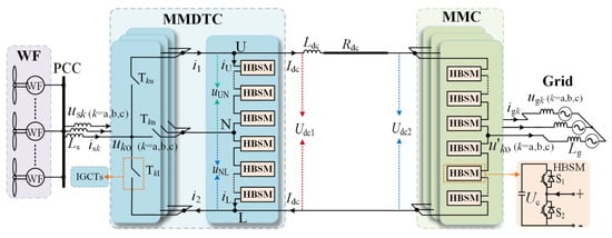
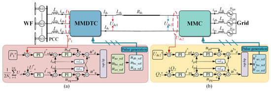
Figure 1 illustrates the MMDTC-MMC hybrid DC transmission system. The MMDTC is used as the sending-end converter and the MMC as the receiving-end converter; the two converters are interconnected by a DC cable whose equivalent resistance is Rdc. A DC smoothing reactor Ldc is connected in series with the DC line to suppress DC-current ripple. The MMDTC consists of a T-type structure and a modular multilevel DC link. The T-type structure is formed by high-voltage switch valves composed of series-connected IGCTs, which operate at a low switching frequency. The DC link is further divided into upper and lower arms, each consisting of N1 cascaded half-bridge submodules (HBSMs) [24]. Correspondingly, the receiving-end MMC adopts a three-phase, six-arm structure, with N2 HBSMs connected in series in each arm.
Figure 1.
Schematic diagram of the MMDTC-MMC hybrid DC transmission system.
The output phase voltage on the MMDTC AC side is defined as:
where V denotes the phase-voltage amplitude and ω denotes the angular frequency of the voltage.
The three-phase output voltages can be further expressed as:
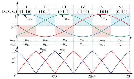
The T-type structure of the MMDTC has three phases, a, b, and c. Each phase consists of upper, middle, and lower high-voltage switches. Define the switching function Sk (k = a, b, c) for each phase, where Sk = 1, 0, and −1 indicate that the upper, middle, and lower switch of phase k is conducting, respectively. As shown in Figure 2, one fundamental-frequency period is divided into six sectors. The states of {Sa, Sb, Sc} in each sector determine the relationship between the upper- and lower-arm voltages and the three-phase output line voltages [27]. From Equation (2) and Figure 2, the mathematical expressions for the upper- and lower-arm output voltages are:
where floor(x) denotes the floor function.
Figure 2.
Relationship between arm voltage and line voltage.
Figure 2 shows that the upper- and lower-arm output voltages have a triple-frequency characteristic, with equal amplitudes and opposite phases. Notably, the arm voltages are always nonnegative. This feature makes a cascade of half-bridge submodules sufficient, without the need for full-bridge submodules. Using the arm voltage as the reference wave and combining it with carrier phase-shifted PWM, a nonnegative multilevel stepped waveform can be generated. Periodic switching of the high-voltage valves in the T-type structure then constructs the three-phase multilevel line-voltage waveform.
3. Steady-State Parameter Analysis and Mathematical Modeling
3.1. Analysis of the Number of Submodules
The MMDTC and MMC are interconnected through the DC line. Under steady-state operation, and neglecting the voltage drop caused by the equivalent impedance of the DC transmission line, the DC terminal voltages of the two converters are approximately equal (i.e., Udc1 ≈ Udc2). Therefore, the DC voltage is the key physical link connecting the mathematical models of the two converters and realizing system-level coupling.
For the sending-end MMDTC, the analytical expression of its DC-side output voltage Udc1 can be derived from the upper- and lower-arm voltage relationships described by Equations (3) and (4):
A Fourier-series expansion of Udc1 further gives the following result after high-order harmonic components are filtered out:
The above equation shows that Udc1 is mainly composed of a steady-state DC component superimposed with a sixth-harmonic AC ripple component. The amplitude of the sixth-harmonic component is only about 5.7% of the DC component. Because this harmonic component is relatively small, the subsequent boundary derivation of the steady-state mathematical model neglects this low-frequency fluctuation and retains only the dominant DC component for theoretical analysis.
According to the basic operating principle of the MMDTC [26], the AC output voltage and submodule voltage satisfy the following constraint:
where N1 denotes the number of submodules in the upper (lower) arm, m1 is the MMDTC modulation index, and Uc is the rated voltage of a submodule capacitor.
1.5V = m1N1Uc
Considering only the DC component in Equation (6), combining Equations (6) and (7) gives:
The number of submodules in an MMDTC arm can then be obtained from Equation (8):
According to the analysis in [15], the relationship between the number of MMC arm submodules N2, the DC voltage, and the submodule capacitor voltage is:
From the hardware-topology perspective, the MMDTC consists of only two DC-link arms, whereas a conventional MMC uses a standard three-phase, six-arm structure. Under steady-state operation, Udc1 ≈ Udc2; therefore, Equations (9) and (10) give the ratio of the total number of submodules required by the MMDTC and MMC:
The above equation shows that the ratio of the required submodule numbers, η1, is inversely proportional to the MMDTC modulation index m1: the larger m1 is, the more significant the MMDTC advantage in reducing the number of submodules. In practical engineering, m1 is generally set to 0.85, yielding a submodule-number ratio of approximately 35.6%. Thus, under the same DC-bus voltage, the total number of submodules required by the MMDTC is only 35.6% of that required by the MMC.
3.2. Analysis of AC- and DC-Side Current Coupling Characteristics for MMDTC
Assume that the AC system operates in a balanced three-phase state. The output current of each MMDTC AC-side phase can be uniformly expressed as:
where I denotes the MMDTC AC-side current amplitude and φ1 is the power-factor angle. According to the operating modes of the T-type structure in Figure 2, the instantaneous upper- and lower-arm currents are:
where iU and iL are the instantaneous currents of the upper and lower MMDTC arms, respectively, and Idc is the DC-line current.
The instantaneous arm power is the key physical quantity determining the energy fluctuation of the submodule capacitors. Combining Equations (3), (4), (13), and (14) gives the instantaneous power of the upper and lower MMDTC arms:
A Fourier-series decomposition is then applied to PU and PL. After neglecting high-order harmonic components that have a negligible effect on the overall characteristics, the instantaneous arm power can be approximated as the sum of a steady-state DC bias component and a triple-frequency AC fluctuation component:
The analytical expressions of the individual parameters after expansion are defined as follows:
Equation (17) shows that the instantaneous arm power is mainly composed of a DC component and a triple-frequency component. The triple-frequency component causes triple-frequency fluctuation of the submodule capacitor voltage, whereas the DC component causes a continuous one-sided drift of the capacitor voltage and destroys the steady-state balance. Therefore, the DC component of the instantaneous arm power is regulated to zero under steady-state operation:
This further gives:
Equation (20) reveals the intrinsic coupling mechanism between the AC- and DC-side currents of the MMDTC. For a constant AC-side output-current amplitude I, the DC-side current Idc is constrained by the AC-side power factor cosφ1, and the two quantities have a definite functional mapping. In particular, when the system operates at unity power factor (i.e., cosφ1 = 1), the corresponding DC current Idc reaches its global maximum.
3.3. The AC-Side Power Factor Analysis for MMDTC
A grid-voltage-oriented vector-control strategy is adopted. In the synchronous rotating dq frame, the voltage vector at the PCC is aligned with the d axis, so usd = Vs and usq = 0. The MMDTC AC-side voltage equation is then:
where ω is the angular frequency of the AC system, isd and isq are the d- and q-axis components of the MMDTC AC current, respectively, and Ls is the MMDTC AC-side filter inductance.
In steady-state operation, the fundamental-frequency voltage drop across the filter inductor is generally required to be no more than 5–10% of the grid phase voltage. Here, the system is assumed to operate at unity power factor, and the fundamental-frequency inductor voltage drop is set to 10%. The required filter inductance Ls can therefore be estimated as:
The active and reactive power output by the MMDTC AC side can then be expressed as:
The amplitude of the MMDTC AC-side output phase voltage can be expressed as:
On the DC side, if high-order harmonics are neglected and only the steady-state DC component of the DC current Idc is considered, its expression is:
Considering energy conservation and voltage coupling between the AC and DC sides, the following expression can be derived by combining Equations (6), (20), (21), (24), and (25):
The analytical expression of the system power factor can therefore be obtained as:
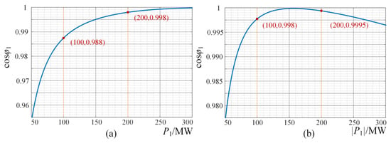
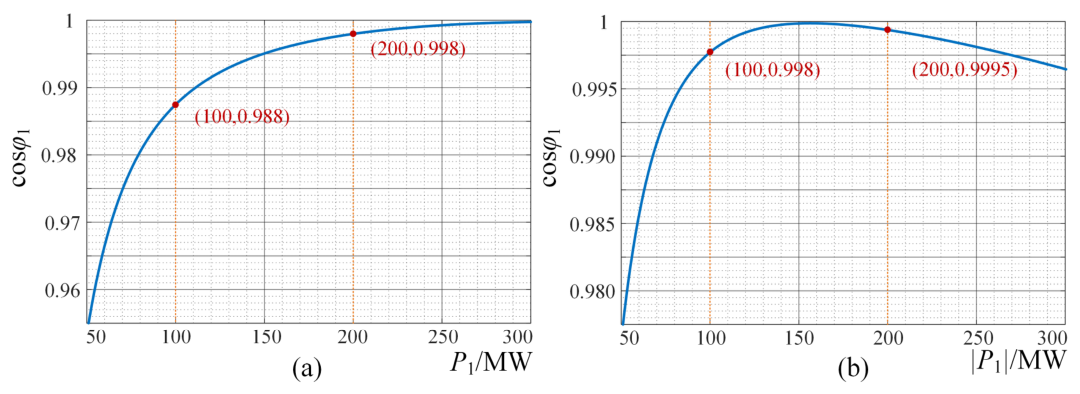
To illustrate the evolution of the MMDTC AC-side power factor, the following system parameters are used as an example. The RMS AC phase voltage at the PCC is set to 85 kV, the rated system power P1 to 200 MW, the rated DC-side voltage to 200 kV, and the equivalent resistance of the DC transmission line to 1 ohm. First, the filter inductance calculated from Equation (22) is Ls = 12.75 mH. Then, using Equations (23), (26), and (27), the nonlinear relationship between the power factor cos(φ1) and active power P1 can be plotted, as shown in Figure 3.
Figure 3.
Power factor cos(φ1) versus active power P1: (a) power transmitted from the MMDTC to the MMC (P1 > 0); (b) power transmitted from the MMC to the MMDTC (P1 < 0).
Figure 3 shows that, to ensure stable operation of the hybrid DC system, the sending-end MMDTC must dynamically adjust its power factor according to the output power. This means that the active- and reactive-power components on the MMDTC AC side are constrained and cannot be controlled independently. Nevertheless, as shown in Figure 3a, when the forward transmitted power is 50% of the rated power, namely P1 = 100 MW, the power factor is cosφ1 = 0.988; at rated transmitted power (200 MW), it increases to 0.998. Figure 3b shows a similar behavior for reverse power transmission. Thus, although the active and reactive components are constrained, operation near rated power is close to unity power factor.
A further analysis of Figure 3 shows that, to ensure global stability of the hybrid DC system, the sending-end MMDTC must dynamically adjust its power factor as the output power changes. This reveals the inherent constraint between the active- and reactive-power components on the MMDTC AC side, which limits the independent decoupling capability compared to a conventional MMC. Figure 3 also demonstrates its engineering value: under forward power flow, the power factor reaches 0.988 when the transmitted power is 50% of the rated capacity (P1 = 100 MW), and rises to 0.998 at the full rated condition (200 MW). Under reverse power flow, Figure 3b shows the same trend. In summary, although the MMDTC topology imposes a physical constraint between active and reactive power, the system can maintain operation close to unity power factor in the medium- and high-load range near rated power, meeting the practical requirements of high-efficiency, high-quality offshore-wind-power integration.
Because reactive power is directly determined by P1 and cos(φ1), this boundary curve essentially reflects the intrinsic active-reactive power (P-Q) coupling boundary of the MMDTC. As shown, unlike the conventional MMC, the maximum achievable active and reactive power ranges of the MMDTC are constrained under different power-factor conditions.
3.4. Analysis of Submodule Capacitance
Based on the steady-state operating constraint derived in Section 3.2, the DC component of the instantaneous arm power is strictly limited to zero. Under this constraint, the instantaneous powers of the upper and lower MMDTC arms can be further simplified to pure AC fluctuation terms by combining Equations (15) and (16):
Assume that the instantaneous arm power is evenly distributed among the cascaded submodules. The instantaneous power borne by an individual submodule is therefore the total arm power divided by the number of submodules. Dynamic integration of this instantaneous power directly causes periodic pulsation of the energy stored in the submodule capacitor, which can be described by the following mathematical relationship:
where Em denotes the amplitude of the capacitor-energy fluctuation and σ denotes the phase-angle offset of the synthesized waveform; their expressions are:
According to the energy-pulsation characteristics above, the difference between the maximum and minimum energy experienced by the capacitor over one complete cycle is the peak-to-peak energy fluctuation ΔE:
From the physical and electrical characteristics of the energy-storage capacitor, the steady-state energy fluctuation ΔE is constrained by the rated DC voltage, the capacitance, and the allowable voltage ripple, and should satisfy the following inherent constraint:
In the above equation, C1 denotes the submodule capacitance and ε1 is the submodule capacitor-voltage ripple ratio.
By combining Equations (31) and (32), and referring to the theoretical capacitor-parameter design model for conventional MMCs in [3], exact analytical expressions for the capacitance requirements of the MMDTC and receiving-end MMC submodules can be derived:
According to the overall energy-conservation law of the AC/DC system, and under the ideal assumption that converter losses are neglected, the active power transmitted by the sending-end MMDTC is equal to that transmitted by the receiving-end MMC, namely 3/2 V′I′ cos(φ2) = 3/2 V I cos(φ1). The ratio of the capacitance requirements of the MMDTC and MMC submodules can therefore be obtained:
Substituting the ratio of the total submodule numbers on the two sides derived in Section 3.1 (Equation (11)) into Equation (34) gives the final analytical model of the capacitance ratio η2:
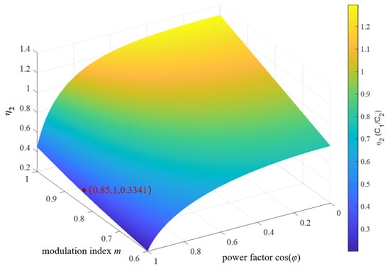
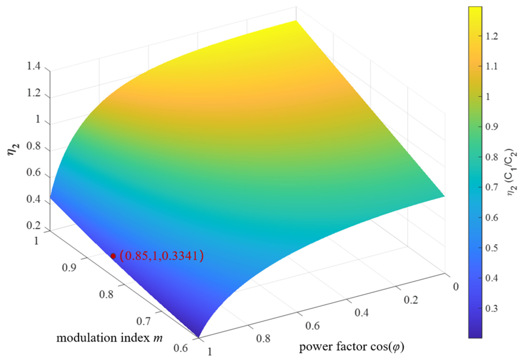
To illustrate the nonlinear influence of system operating variables on the capacitance ratio η2, both converters are assumed to operate with symmetric modulation and the same power factor (i.e., m1 = m2 = m and φ1 = φ2 = φ). Under this condition, the three-dimensional surface of η2 as a function of modulation index m and power factor cos(φ1) is shown in Figure 4.
Figure 4.
Three-dimensional relationship between capacitance ratio η2, modulation index m, and power-factor angle cos(φ).
The three-dimensional surface in Figure 4 shows that the capacitance ratio η2 decreases monotonically as the modulation index m decreases, indicating that the topological advantage of the MMDTC in reducing capacitor volume becomes more pronounced at a lower modulation index. Meanwhile, η2 decreases as the power factor cosφ increases; that is, the closer the system operates to unity power factor, the greater the reduction in capacitance achieved by the MMDTC. Under a typical engineering condition, assuming a rated modulation index of m = 0.85 and unity power factor (cosφ = 1), the corresponding surface point gives η2 = 33.41%. This result confirms that, under the same transmission capacity and operating boundaries, the submodule capacitance required by the proposed MMDTC is only 33.41% of that required by a conventional MMC, significantly mitigating the bulky energy-storage capacitor bottleneck that has long constrained the volume and load-bearing requirements of offshore converter platforms.
It is worth emphasizing the sensitivity and robustness of these theoretical reduction ratios. According to the derivations, the absolute capacitance values for both converters scale proportionally with the transmitted power and inversely with the allowable ripple requirement. Consequently, these two operating variables mathematically cancel out in the ratio η2. This indicates that the MMDTC’s advantage in footprint reduction is an inherent topological characteristic, completely immune to variations in power rating or ripple stringency. Furthermore, within the practical HVDC modulation index boundary (typically m in [0.80, 0.95]) and standard offshore wind power factor ranges (cosφ > 0.9), the 3D parametric surface in Figure 4 confirms that η2 remains firmly bounded below 45%. This parametric analysis demonstrates that the significant compacting advantage of the proposed MMDTC-MMC system is highly robust across the entire practical operating envelope.
3.5. Analysis of Submodule Current Stress
For the sending-end MMDTC, substituting the DC-current constraint derived from Equation (20) into the arm transient-current model (Equations (13) and (14)) gives the complete analytical expressions for the steady-state upper- and lower-arm currents:
The peak and RMS currents flowing through the submodules can then be obtained as:
Furthermore, based on the AC-side phase-voltage model derived in Section 3.2 and the analysis of the AC/DC voltage conversion ratio of conventional MMCs in [29], the mapping relationships between the AC-side output phase-voltage amplitudes and the DC-side bus voltage can be established for the MMDTC and MMC, respectively:
Because the DC-side bus voltages are approximately equal during steady-state power transmission (i.e., Udc1 ≈ Udc2), and based on the active-power balance boundary of the AC/DC system, Equation (40) can be used to derive the inherent ratio between the AC-side phase-current amplitudes of the MMDTC and the receiving-end MMC:
For the MMC, according to the analysis in [30], the peak and RMS currents flowing through the submodules are:
Based on the above theoretical models, the exact analytical expressions for the ratio η3 of the current peaks and the ratio η4 of the RMS currents borne by MMDTC and MMC submodule devices can be derived to quantitatively compare the current burden of the two topologies:
Substituting typical steady-state operating parameters from practical engineering into the above equation (the receiving-end MMC modulation index is set to m2 = 0.85, and both converters operate at unity power factor, cos(φ1) = cos(φ2) = 1) gives η3 = 1.88 and η4 = 2.11. This quantitative assessment objectively reveals the trade-off introduced by the topology evolution: under the same DC-bus voltage and the same rated active-power transmission, the current peak and RMS value borne by the devices inside a single MMDTC submodule are 1.88 and 2.11 times those of the conventional MMC, respectively. Thus, although the MMDTC topology greatly reduces the total number of submodules and sharply compresses the volume of passive energy-storage capacitors to achieve a highly compact converter platform, it does so at the cost of higher current stress on individual active-power devices.
3.6. Smoothing-Reactor Parameter Design
The Fourier analysis in Section 3.1 shows that the MMDTC sending-end DC output voltage Udc1 contains low-frequency AC pulsation dominated by the sixth harmonic, with an amplitude of approximately 5.7% of the steady-state DC component. This harmonic-voltage disturbance is the main source of DC-line current ripple. To effectively suppress the injection of high-frequency harmonic current into the DC transmission network, a high-capacity smoothing reactor is generally connected in series between the MMDTC DC terminal and the DC transmission cable.
Neglecting the ripple voltage at the MMC DC terminal, the equivalent circuit of the sixth harmonic on the DC side can be expressed as:
where ω = 2πf, f is the fundamental frequency of the AC system, Udc6 is the amplitude of the sixth-harmonic component of the MMDTC DC voltage, Ldc is the smoothing-reactor inductance, and Rdc is the equivalent resistance of the DC cable.
In practical HVDC transmission projects, for relatively high-order harmonics such as the sixth harmonic, the reactance of the smoothing reactor is much larger than the ohmic resistance of the DC line (i.e., 6ωLdc >> Rdc). Therefore, the above equation can be simplified as:
The primary optimization objective in designing the key parameters of the smoothing reactor is to limit DC-side current ripple to a safe range. In engineering specifications, the maximum allowable ripple current is usually expressed as a specified percentage of the rated steady-state DC current Idc:
where ε6’ is the allowable ripple coefficient. Its selection must balance the safety margin of converter power devices, the thermal-stability limit of the DC cable, and the power-quality requirements of the entire grid. Its engineering range is generally 1–5%. Combining Equations (46) and (47) gives the critical inductance design criterion for the smoothing reactor that satisfies the system ripple-suppression requirements:
Idc6,allow = ε′6 ⋅ Idc
4. Decoupled Dual-Loop Control Strategy
4.1. Overview of the Control-Strategy Architecture
The physical law revealed by Equation (7) shows that the AC- and DC-side voltages of the MMDTC have a direct algebraic coupling relationship, and the DC-terminal voltage is constrained by the AC-side output voltage. This means that the sending-end MMDTC itself has limited independent control freedom over the DC-bus voltage. Therefore, in the coordinated control of the MMDTC-MMC hybrid DC transmission system, the receiving-end MMC, which has more control degrees of freedom, can undertake the central task of maintaining DC-bus-voltage stability.
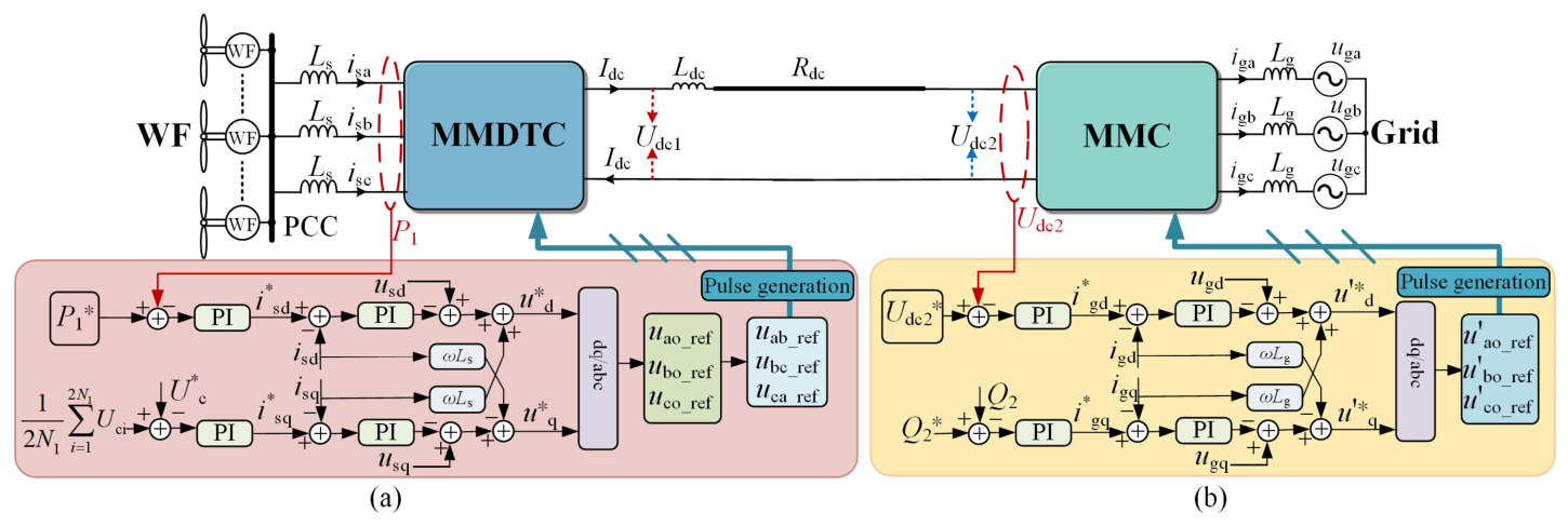
Accordingly, this paper designs a coordinated dual-loop decoupled control architecture. The sending-end MMDTC uses constant-active-power control to govern the transmission of offshore wind-power energy and is supplemented by an adaptive submodule-capacitor-voltage closed loop to handle the AC/DC coupling constraint. The receiving-end MMC uses constant-DC-voltage and constant-reactive-power control to stabilize the DC bus and support the onshore AC grid. The overall control block diagram is shown in Figure 5.
Figure 5.
Control block diagram of the MMDTC-MMC hybrid DC transmission system: (a) constant-active-power control with an adaptive submodule-capacitor-voltage closed loop; (b) constant-DC-voltage and constant-reactive-power control.
4.2. Constant-Active-Power Control and Adaptive Submodule-Capacitor-Voltage Closed Loop of Sending-End MMDTC
The steady-state boundary analysis in Section 3.2 and Section 3.3 shows that the active- and reactive-power components output by the MMDTC AC side are subject to an inherent physical constraint because of the direct coupling between the AC- and DC-side voltages. If an open-loop feedforward calculation based on the steady-state algebraic equations is used to generate the reactive-power reference, the system depends heavily on hardware parameters such as the filter inductance and is highly susceptible to nonlinear dead zones and measurement noise, which can cause steady-state-point drift or even instability.
For the sending-end MMDTC, this paper therefore proposes a reactive-power generation strategy based on an adaptive submodule-capacitor-voltage closed loop. The physical basis is that the MMDTC submodule capacitors act as natural physical integrators of the energy imbalance between the AC and DC sides. When the active power transmitted on the AC side does not match the DC output power, the energy difference is directly reflected in the deviation of the average submodule-capacitor voltage from its rated reference U*c.
To verify the feasibility of this closed-loop control, the mathematical relationship between the AC-side voltage amplitude V and the reactive current isq is further analyzed. In the grid-voltage-oriented synchronous rotating dq frame (with usd = Vs and usq = 0), the AC-side Kirchhoff voltage law gives the following vector equation for the synthesized amplitude V of the MMDTC output phase voltage:
Assuming that the active current isd is maintained constant by the system outer-loop dispatch, differentiating both sides of the above equation with respect to the reactive current isq gives the analytical sensitivity of voltage amplitude to reactive current:
In practical HVDC projects, the steady-state voltage drop across the filter inductance (ωLsisq) is much smaller than the grid phase-voltage reference Vs. Therefore, (Vs + ωLsisq) > 0 over the full operating range, which directly ensures that ∂V/∂isq>0. The positive polarity of this partial derivative proves that increasing the q-axis reactive current isq necessarily increases the MMDTC AC-side output-voltage amplitude V monotonically.
Based on this polarity relationship, when the capacitor voltage is higher than its rated value (Uc > U*c), the system must increase the positive reactive current isq to raise the synthesized AC voltage V and thereby deliver more energy to the high-voltage DC side. In the control architecture, the active-power outer loop independently generates the d-axis active-current reference i*sd from the dispatch command. The reactive-power branch constructs a submodule-capacitor-voltage outer loop, samples the capacitor voltages of all 2N1 MMDTC submodules in real time, and calculates their average. To match the positive control polarity described above, the deviation between the measured average and the rated reference U*c is sent to a PI controller, which directly generates the q-axis reactive-current reference i*sq:
where Kp, Uc, Ki, Uc are positive-gain PI-controller parameters. This closed-loop mechanism allows the MMDTC to automatically optimize the reactive current from the capacitor-voltage feedback response without relying on precise hardware parameters. It satisfies the rigid AC/DC voltage-coupling constraint and ensures the steady-state constraint and overvoltage safety of the submodule capacitors.
The inner current loop uses feedforward decoupling. Taking current flowing from the AC system into the MMDTC as the positive direction, the MMDTC AC-side voltage reference is:
where Kp,i, Ki,i are the PI-controller parameters of the inner current loop.
According to Equation (44), the feedforward terms ωLsisq and -ωLsisd dynamically decouple the d- and q-axis currents. The inner current loop responds much faster than the outer power loop, so the current commands generated by the outer loop can be regarded as steady-state references for the inner loop.
4.3. Constant-DC-Voltage and Constant-Reactive-Power Control of Receiving-End MMC
Unlike the sending-end MMDTC, the receiving-end MMC has an inherent decoupling between its AC and DC sides because the half-bridge submodule capacitors can independently establish voltage. Therefore, it has two independent control degrees of freedom. Its primary task is to maintain the DC-bus voltage Udc2 constant, thereby ensuring the transient and steady-state active-power balance of the DC line.
In the control structure, the DC-voltage outer loop uses a PI controller to generate the d-axis active-current reference:
where U*dc2 is the DC-voltage reference, Udc2 is the measured receiving-end DC voltage, and Ki,dc is a parameter of the DC-voltage outer-loop PI controller.
The receiving-end MMC AC-side active power and DC-side power satisfy:
The logical relationship between the two equations shows that, when the DC voltage in the network deviates from its reference, the DC-voltage outer loop automatically adjusts and outputs a new active-current command. By regulating the active power exchanged between the receiving-end MMC and the onshore AC grid, this mechanism changes the energy stored on the DC side during the transient and ultimately forces the DC voltage to return dynamically to its rated reference.
At the same time, the receiving-end MMC uses the q-axis current to independently control reactive power, whose output satisfies:
The corresponding reactive-power outer-loop control equation is:
where Q*2 is the receiving-end reactive-power reference, and Kp,Q2, Ki,Q2 are the PI-controller parameters of the reactive-power outer loop. Because the q-axis current is decoupled from active power and DC voltage, the receiving-end MMC can independently regulate the reactive power exchanged with the onshore AC grid without affecting the DC voltage or active-power transmission, thereby satisfying the grid reactive-power requirement.
The receiving-end MMC inner current-loop structure is similar to that of the sending end and likewise uses a grid-voltage-oriented feedforward decoupling strategy to generate the final modulation-voltage reference:
where Lg is the equivalent inductance between the receiving-end MMC and the AC grid.
5. Comprehensive Comparison of Typical DC Transmission Systems
To highlight the balance achieved by the proposed MMDTC-MMC hybrid DC transmission system among space occupation, hardware cost, and control performance, this section compares it with three mainstream topologies in offshore-wind-power DC transmission: conventional MMC-MMC, DRU-MMC, and LCC-MMC systems. The overall performance is listed in Table 1.
Table 1.
Comparison of hybrid DC transmission-system topologies.
Regarding hardware cost and offshore-platform space, the conventional MMC-MMC solution ranks first in platform volume and investment cost because each phase arm requires many cascaded submodules and large energy-storage capacitors. In contrast, DRU-MMC and LCC-MMC eliminate many fully controllable devices and submodule capacitors, so their converter or structural cost is lower. However, because their sending-end converters lack active support capability, large reactive-power compensation equipment, AC filters, and auxiliary synchronous condensers must be installed on the offshore platform, seriously eroding their space advantage. In the proposed MMDTC-MMC system, the sending-end MMDTC uses a carefully reconstructed topology to reduce the total number of submodules and the capacitance to 35.6% and 33.41%, respectively, of the conventional MMC values at the same DC voltage. Although the MMDTC introduces a high-voltage IGCT switch-valve group, it removes the distributed high-capacity energy-storage capacitors, and the IGCTs operate only at fundamental or low frequency with very low switching losses. Consequently, the overall cooling auxiliaries and physical platform volume remain highly compact, achieving genuine hardware compacting for offshore wind power.
In terms of controllability and grid-support capability, the sending ends of DRU-MMC and LCC-MMC use diodes or thyristors, so power transfer is unidirectional and the sending-end AC voltage must be supported by the offshore wind farm. More importantly, these topologies cannot transmit power in reverse and cannot realize a black start of the offshore converter station through the DC system. As a fully controlled hybrid topology, MMDTC-MMC inherits the core electrical advantages of MMC-MMC, including flexible bidirectional active-power flow and reverse power transmission from the receiving-end converter station. In addition, its output terminal uses a multilevel stepped waveform with very low AC-side harmonic content and does not require a bulky AC filter.
Regarding AC/DC interaction, a conventional MMC has no fixed proportional constraint between its AC- and DC-side voltages and can realize fully independent decoupled control. The MMDTC, however, is similar to the DRU and LCC in that its DC-side voltage and AC-side output voltage have a direct algebraic coupling relationship.
In addition, to comprehensively evaluate the system efficiency and compactness, the inherent trade-off between the reduced submodule count and the increased device current stress must be analyzed. As derived in Equation (44), the per-device RMS current in the MMDTC is 2.11 times that of a conventional MMC. This inevitably increases the localized conduction losses and thermal dissipation requirements per submodule, necessitating power devices with higher current ratings and upgraded cooling systems. However, from a system-level perspective, the total number of HBSMs is drastically reduced by approximately 64.4%. Furthermore, the high-voltage IGCT valves in the T-type structure operate at very low switching frequencies, resulting in negligible switching losses. Consequently, the overall semiconductor losses of the MMDTC are estimated to be comparable to or only slightly higher than those of a conventional MMC. More importantly, in offshore converter platforms, the physical footprint and weight are overwhelmingly dominated by the bulky passive energy-storage capacitors rather than the semiconductor heat sinks. The 66.59% reduction in total capacitance volume far outweighs the added volume of the upgraded cooling system, confirming the substantial overall optimization in platform compactness and investment cost.
6. Simulation Verification
6.1. Simulation Parameter Configuration
A MMDTC-MMC hybrid transmission system with a rated output power of 200 MW, a rated DC voltage of 200 kV, and a 100 km DC cable is built in MATLAB/Simulink. Setting Uc = 800 V and substituting Udc1 = Udc2 = 200 kV and m1 = 0.85 into Equations (9) and (10) gives the numbers of submodules per arm for the MMDTC and MMC as N1 = 267 and N2 = 250, respectively. With ε1 = 5%, the required submodule capacitances are C1 ≥ 1.42 mF and C2 ≥ 4.27 mF; this paper selects C1 = 1.5 mF and C2 = 4.5 mF. The main simulation parameters are listed in Table 2. According to Equation (48), the smoothing-reactor inductance must satisfy Ldc ≥ 41 mH; Ldc = 50 mH is selected.
Table 2.
Main simulation parameters.
6.2. Steady-State Operating Performance
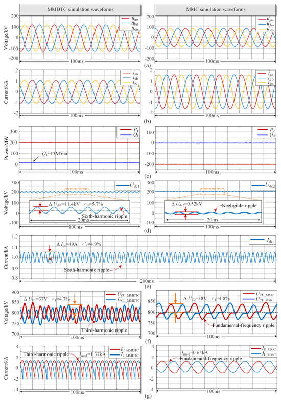
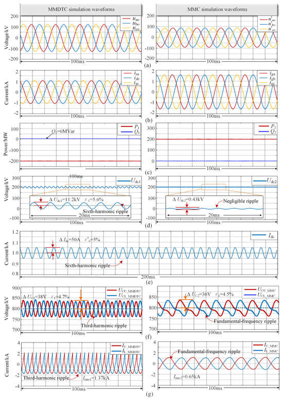
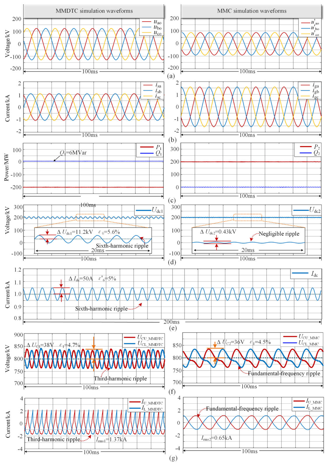
Figure 6 presents the simulated waveforms when active power is transmitted from the MMDTC to the MMC under steady-state conditions. Figure 6a,b show the AC-side voltages and currents of the MMDTC and MMC, respectively. The three-phase AC output voltages of both converters are multilevel and closely approximate sinusoidal waveforms. The MMDTC-side voltage amplitude is approximately 142.5% of the MMC-side value, whereas its current amplitude is approximately 70.27% of the MMC-side value. Their power levels are therefore essentially the same, verifying balanced power transmission. Figure 6c shows that the MMDTC active power is 200 MW and its reactive power is only 13 Mvar. This reactive power is produced by the coupling between the MMDTC AC- and DC-side voltages to regulate the DC-side voltage, which agrees with the theoretical analysis in Section 3.3. Figure 6d shows the DC-side voltage. The MMC-side DC voltage Udc2 contains only a DC component, whereas the MMDTC-side voltage Udc1 contains a sixth-harmonic ripple component whose amplitude is approximately 5.7% of the DC component, consistent with the theoretical analysis of Equation (6). However, Figure 6e shows that the sixth-harmonic component of the DC current accounts for only 4.9% of its DC component, owing to suppression by the DC smoothing reactor.
Figure 6.
Simulated waveforms for power transmission from the MMDTC to the MMC: (a) three-phase AC-side output voltage; (b) three-phase AC output current; (c) output power; (d) DC-side voltage; (e) DC current; (f) submodule capacitor voltage; (g) arm current.
Figure 6f shows the capacitor-voltage waveforms of several submodules in the upper and lower arms. The MMDTC submodule capacitor voltage has a triple-frequency ripple, whereas the MMC submodule capacitor voltage has a fundamental-frequency ripple. The two capacitor-voltage ripple ratios are approximately equal. However, Table 2 shows that the MMDTC submodule capacitance is only one-third of the MMC value. Therefore, the MMDTC can significantly reduce the required submodule capacitance while maintaining the same ripple ratio. Figure 6g shows the arm currents. The MMDTC arm current has a triple-frequency ripple, with a peak value of 2113 A and an RMS value of 1370 A. The MMC arm current has a fundamental-frequency ripple, with a peak value of 1123 A and an RMS value of 650 A. These results agree with the theoretical analysis in Section 3.4.
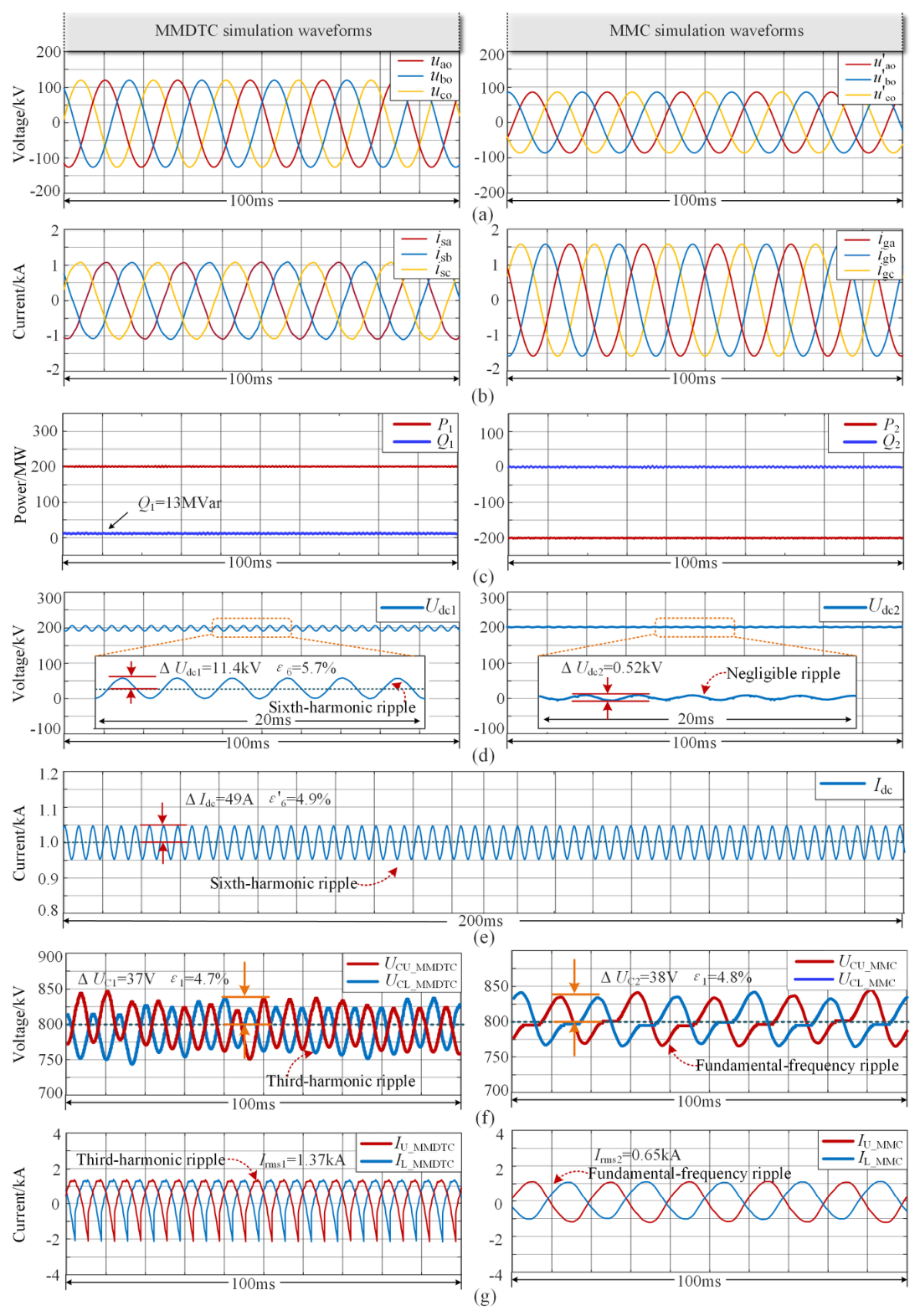
When power is transmitted in the reverse direction, namely from the MMC to the MMDTC, the simulated waveforms are shown in Figure 7. Compared with Figure 6, the waveforms are essentially the same except for the current direction. Figure 6 and Figure 7 show that the proposed MMDTC-MMC hybrid transmission system can transmit active power bidirectionally.
Figure 7.
Simulated waveforms for power transmission from the MMC to the MMDTC: (a) three-phase AC-side output voltage; (b) three-phase AC output current; (c) output power; (d) DC-side voltage; (e) DC current; (f) submodule capacitor voltage; (g) arm current.
6.3. Transient Dynamic Response
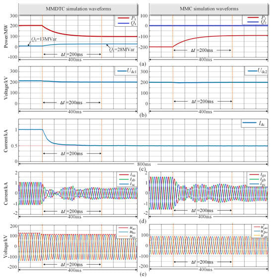
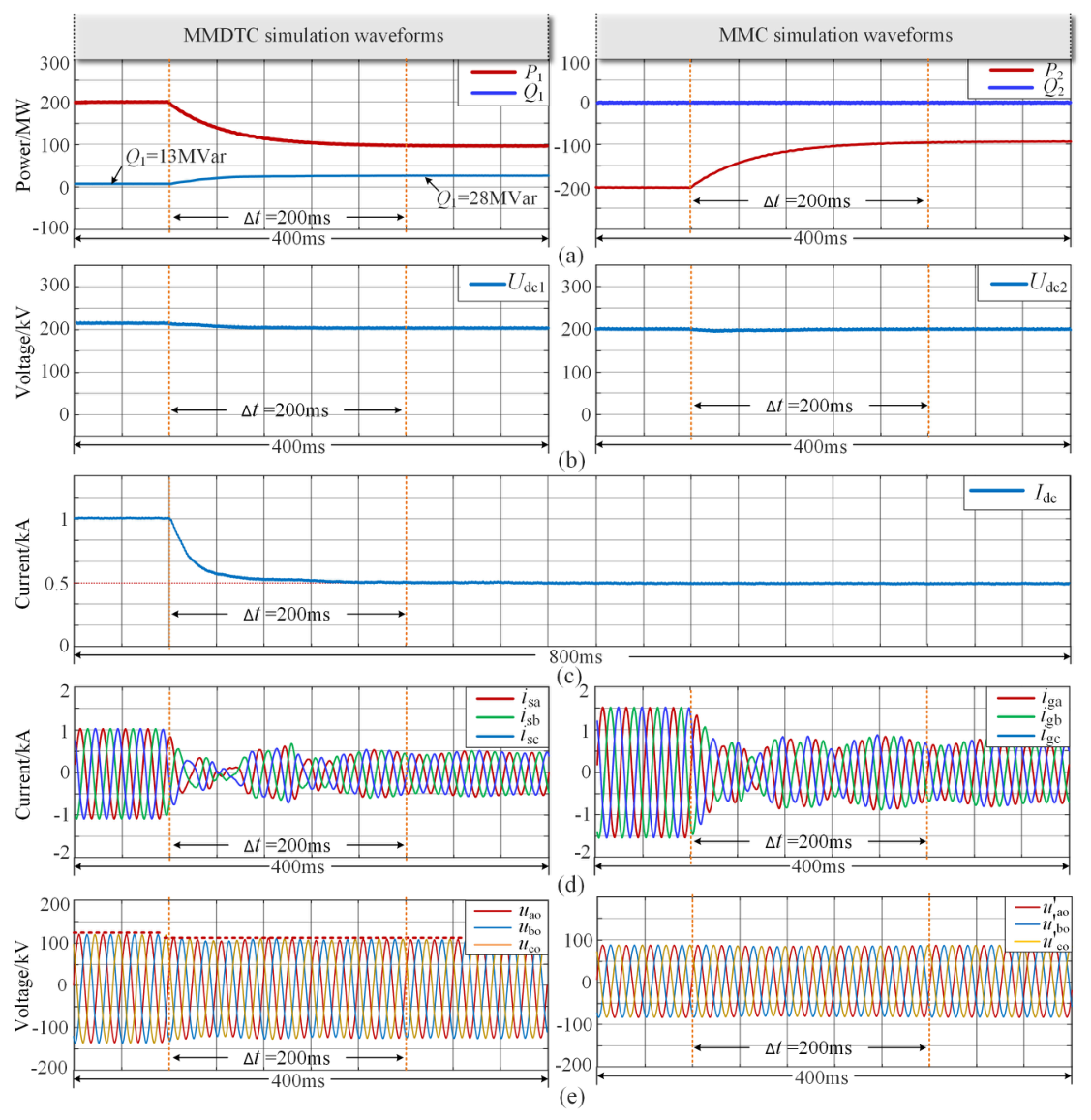
To evaluate the dynamic response of the MMDTC-MMC hybrid DC transmission system under transient conditions, an active-power step is applied at time t0 in the simulation, with the reference changing from 200 MW to 100 MW. The corresponding results are shown in Figure 8. Figure 8a shows that, after the power-reference step, the active powers P1 of the sending-end MMDTC and P2 of the receiving-end MMC rapidly track the reference change and smoothly reach new steady-state values, with a stable dynamic response. The reactive power absorbed by the MMDTC, Q1, increases from 13 Mvar to 28 Mvar, whereas Q2 remains essentially unchanged. This indicates that the MMDTC reactive power changes with active power, while the MMC reactive power can be controlled independently.
Figure 8.
Simulated waveforms under an active-power step during transmission from the MMDTC to the MMC: (a) active and reactive power; (b) DC-side voltage; (c) DC current; (d) three-phase AC-side output current; (e) three-phase AC-side output voltage.
Figure 8b shows the response of the DC-side voltages. After the power decreases, the MMDTC-side DC voltage Udc1 decreases slightly, whereas the receiving-end MMC-side voltage Udc2 remains essentially constant, consistent with the theoretical expectation of the control strategy in Figure 5. The DC-current waveform in Figure 8c reflects the power change more directly: its amplitude decreases by approximately 50%, consistent with the power-change ratio. Figure 8d shows the three-phase AC-side output currents. After a brief dynamic adjustment, the currents quickly become stable and their amplitudes also decrease by approximately 50%, demonstrating good transient response. Figure 8e shows the three-phase AC output voltages; the MMDTC-side output-voltage amplitude decreases slightly. This is because the MMDTC AC- and DC-side output voltages are coupled, so changing Udc1 requires a corresponding adjustment of the AC-side output-voltage amplitude, consistent with the theoretical analysis above.
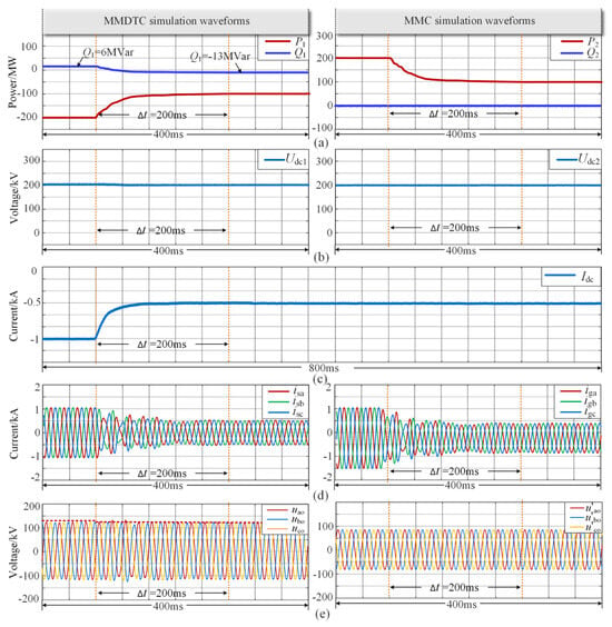
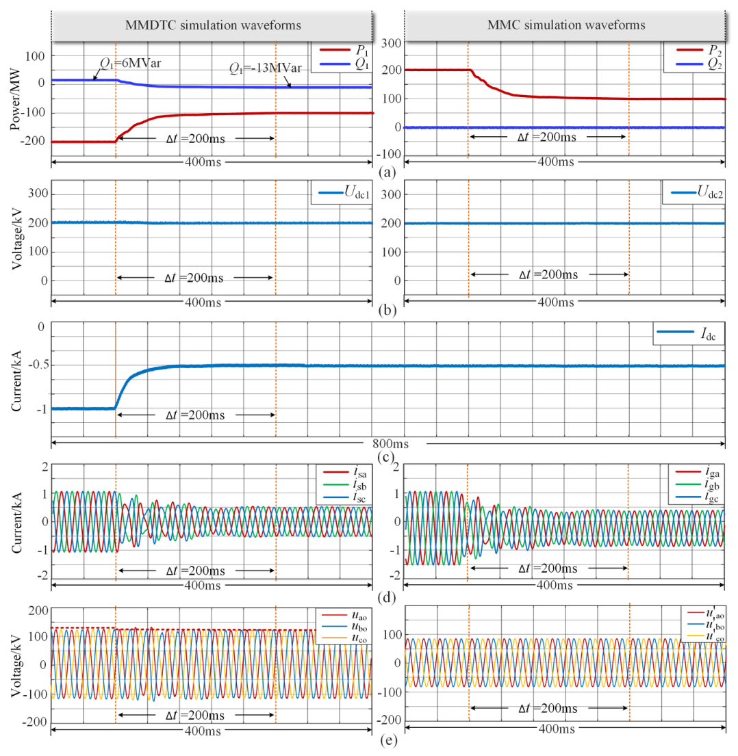
To evaluate the dynamic response of the MMDTC-MMC hybrid DC transmission system under reverse power transmission, an active-power step is applied at time t0 in the simulation, with the reference changing from 200 MW to 100 MW. The corresponding results are shown in Figure 9. Figure 9a shows that Q1 decreases from 6 Mvar to -13 Mvar, whereas Q2 remains essentially unchanged. This again demonstrates that the MMDTC reactive power depends on the active-power variation.
Figure 9.
Simulated waveforms under an active-power step during transmission from the MMC to the MMDTC: (a) active and reactive power; (b) DC-side voltage; (c) DC current; (d) three-phase AC-side output current; (e) three-phase AC-side output voltage.
7. Discussion
To comprehensively assess the practical feasibility of the proposed MMDTC, its intrinsic trade-offs must be objectively discussed. First, the increased current stress on individual devices necessitates the selection of semiconductors with higher current ratings, which will inevitably increase the individual component cost. Second, regarding system efficiency, the total conduction loss is defined by the single-device loss multiplied by the number of conducting devices. Although the unit conduction loss increases, the total submodule count is drastically reduced by approximately 64.4%. This direct offset ensures that the overall conduction loss does not deteriorate significantly. Third, from a thermal management perspective, while the higher loss per device raises the localized heat dissipation requirements for individual switches, the massive reduction in the total component count ensures that the overall cooling capacity requirement of the system does not increase substantially. Ultimately, considering that the capital expenditure of offshore platforms is limited by weight and footprint, the substantial economic savings derived from reducing the total submodule count and passive capacitor volume are more than sufficient to offset the localized costs of upgrading device ratings and enhancing component-level cooling. Therefore, the MMDTC exhibits high practical feasibility for offshore HVDC applications.
While the proposed MMDTC-MMC hybrid topology achieves a highly compact design and significant cost reduction for offshore platforms by utilizing HBSMs, this structural choice introduces inherent limitations regarding DC fault ride-through capability. Unlike topologies employing full-bridge submodules (FBSMs), HBSMs cannot generate negative voltages to actively block fault currents. Consequently, the current MMDTC-MMC configuration necessitates the installation of high-capacity ultra-fast DC circuit breakers at the converter terminals to quickly isolate DC faults. Alternatively, the topology could be evolved into a hybrid submodule configuration, such as substituting a portion of the HBSMs with FBSMs to acquire self-blocking capabilities, which will be the central focus of our future work.
8. Conclusions
This paper proposes a lightweight MMDTC-MMC hybrid HVDC transmission system tailored for offshore wind integration. Based on the theoretical modeling, control design, and comprehensive simulation validations, the detailed structured conclusions are drawn as follows:
(1) Topological Mechanism: By utilizing a T-type structure operating at fundamental frequencies on the sending end, the intrinsic physical bottleneck of conventional MMCs—the rigid coupling between the submodule count and the AC grid voltage—is fundamentally broken, allowing for massive footprint compaction without losing fully-controlled capabilities.
(2) Theoretical Volume-Reduction Boundaries: The derived steady-state analytical models quantify the hardware optimization. Under identical modulation and ripple constraints, the proposed MMDTC requires only 35.6% of the submodules and 33.41% of the total passive capacitance compared to a conventional MMC benchmark, providing economic and dimensional value for offshore platforms.
(3) Decoupled Control and Dynamic Robustness: The proposed coordinated dual-loop decoupled strategy, featuring an adaptive capacitor-voltage feedback loop, successfully overcomes the strong internal active/reactive power coupling. Quantitative transient evaluations demonstrate dynamic robustness: during a severe 50% active-power step, the system stabilizes within 150 ms, while maintaining the DC current ripple below the designed 5.0% threshold.
(4) Limitations and Future Work: While highly compact, the reliance on half-bridge submodules intrinsically limits the system’s DC fault-blocking capability, necessitating ultra-fast DC circuit breakers in practical engineering. Investigating hybrid-submodule configurations to acquire self-blocking abilities and integrating grid-forming control to handle extreme weak-grid disturbances will be the primary focus of our future work.
Author Contributions
Conceptualization, D.N.; Methodology, Q.Z.; Validation, Z.N., P.G. and Z.W.; Formal analysis, L.Z.; Investigation, Q.Z.; Resources, L.Z.; Data curation, P.G. and Z.W.; Writing—original draft, Z.N.; Writing—review & editing, D.N.; Visualization, D.Y.; Supervision, D.Y. All authors have read and agreed to the published version of the manuscript.
Funding
This work is supported by the Science and Technology Research Foundation of Institute of Electrical Engineering of Chinese Academy of Sciences (IEERF250308), the Natural Science Foundation of China (52407113), the Natural Science Foundation of Shandong Province (ZR2024ME075), and the Youth Science and Technology Innovation Support Program for Higher Education Institutions of Shandong Province (2024KJH134).
Data Availability Statement
The data presented in this study are available on request from the corresponding author.
Conflicts of Interest
The authors declare no conflict of interest.
References
- Krishnamoorthy, H.; Daniel, M.; Ramos-Ruiz, J.; Enjeti, P.; Liu, L.; Aeloiza, E. Isolated AC-DC converter using medium-frequency transformer for offshore wind turbine DC collection grid. IEEE Trans. Ind. Electron. 2017, 64, 8939–8947. [Google Scholar] [CrossRef] [Scilit]
- Khan, W.A.; Usman, H.F.; Raza, A.; Abbas, S.K.; Yousaf, A.; Ellahi, M. A scheme for transfer of load between HVDC and HVAC link. In Proceedings of the 2022 International Conference on Engineering and Emerging Technologies (ICEET), Kuala Lumpur, Malaysia, 27–28 October 2022. [Google Scholar]
- Li, Z.; Gao, F.; Xu, F.; Ma, X.; Chu, Z.; Wang, P.; Gou, R.; Li, Y. Power module capacitor voltage balancing method for a ±350-kV/1000-MW modular multilevel converter. IEEE Trans. Power Electron. 2016, 31, 3977–3984. [Google Scholar] [CrossRef] [Scilit]
- Xu, J.; Deng, W.; Gao, C.; Lu, F.; Liang, J.; Zhao, C.; Li, G. Dual harmonic injection for reducing the submodule capacitor voltage ripples of hybrid MMC. IEEE J. Emerg. Sel. Top. Power Electron. 2021, 9, 3622–3633. [Google Scholar] [CrossRef] [Scilit]
- Dai, L.; Deng, C.; Chao, W.; Wang, J.; Huang, J. Research on control strategy and simulation of MMC-HVDC system based on battery energy storage system. In Proceedings of the 2023 3rd International Conference on Electrical Engineering and Control Science (IC2ECS), Hangzhou, China, 29–31 December 2023. [Google Scholar]
- Xu, L.; Liu, C.; Zhang, J.; Tian, Z.; Feng, P.; Liu, S.; Liu, F. Grid-supporting characterization of MMC-HVDC system for offshore wind farm under different control modes: A comparative study. In Proceedings of the 2024 IEEE 10th International Power Electronics and Motion Control Conference (IPEMC2024-ECCE Asia), Chengdu, China, 17–20 May 2024. [Google Scholar]
- Sun, Y.; Zhang, Y.; Ma, L.; Xu, S.; Li, Z. Stability analysis and oscillation mechanism of offshore wind-PV-storage integrated via MMC-HVDC system. In Proceedings of the 2025 5th International Conference on Electrical Engineering and Control Science (IC2ECS), Beijing, China, 5–7 December 2025. [Google Scholar]
- Su, Y.; Xin, Q.; Cao, R.; Xie, H.; Liu, H.; Zhao, X.; Guo, L.; Qin, K. Research on the mechanism and evaluation method of DC-side harmonic oscillation of LCC-HVDC system. In Proceedings of the 2023 International Conference on Power Energy Systems and Applications (ICoPESA), Nanjing, China, 24–26 February 2023. [Google Scholar]
- Shi, L.; Adam, G.P.; Li, R.; Xu, L. Interoperability assessment of MMC and DRU connected offshore wind farms in meshed multi-terminal DC grids. In Proceedings of the 8th Renewable Power Generation Conference (RPG 2019), Shanghai, China, 24–25 October 2019. [Google Scholar]
- Li, R.; Yu, L.; Xu, L.; Adam, G.P. DC fault protection of diode-rectifier-unit-based HVDC system connecting offshore wind farms. In Proceedings of the 2018 IEEE Power & Energy Society General Meeting (PESGM), Portland, OR, USA, 5–10 August 2018. [Google Scholar]
- Ren, X.; Yu, H.; Cai, X.; Yang, R.; Fen, W.; Zhang, Z.; Peng, G.; Liu, H. A novel scheme for DRU-HVDC transmitted offshore wind farm. In Proceedings of the 2023 IEEE Sustainable Power and Energy Conference (iSPEC), Chongqing, China, 28–30 November 2023. [Google Scholar]
- Yu, M.; Wang, Y.; Bao, S.; Huang, Y.; Pei, Z.; Chen, X. Simulation analysis of fault characteristics of offshore wind power DC delivery system based on hybrid series connection of DRU and MMC. In Proceedings of the 2025 2nd International Symposium on New Energy Technologies and Power Systems (NETPS), Hangzhou, China, 23–25 May 2025. [Google Scholar]
- Pei, X.; Wu, H.; Xu, Y.; Cheng, X.; Zhang, Q.; Zhang, Z.; Liang, P.; Xu, Z. Overvoltage research and insulation coordination for HVDC transmission system based on medium-frequency DRU-MMC. In Proceedings of the 2023 IEEE 7th Conference on Energy Internet and Energy System Integration (EI2), Hangzhou, China, 15–18 December 2023. [Google Scholar]
- Wang, H.; Pan, X.; Chen, Y.; Chen, X.; Zhang, J. Offshore wind farm low-frequency transmission empirical system based on DRU-MMC topology. In Proceedings of the 2024 IEEE 6th International Conference on Power, Intelligent Computing and Systems (ICPICS), Shenyang, China, 26–28 July 2024. [Google Scholar]
- Chang, X.; Wang, X.; Long, X.; Chen, W.; Yan, M.; Ni, J.; Chen, Q. Design and adaptive harmonic suppression method of series-connected transformerless hybrid MMC-DRU for offshore wind farms. In Proceedings of the 2026 IEEE 4th International Conference on Power Science and Technology (ICPST), Hohhot, China, 15–18 May 2026. [Google Scholar]
- Lesnicar, A.; Marquardt, R. An innovative modular multilevel converter topology suitable for a wide power range. In Proceedings of the 2003 IEEE Bologna Power Tech Conference Proceedings, Bologna, Italy, 23–26 June 2003. [Google Scholar]
- Liu, H.; Dahidah, M.S.A.; Yu, J.; Naayagi, R.T.; Armstrong, M. Design and control of unidirectional DC-DC modular multilevel converter for offshore DC collection point: Theoretical analysis and experimental validation. IEEE Trans. Power Electron. 2019, 34, 5191–5208. [Google Scholar] [CrossRef] [Scilit]
- Yang, W.; Lu, Z.; Xu, Y.; Qiao, G. MMC-HVDC system high-frequency resonance suppression method based on capacitive filter. In Proceedings of the 2024 14th International Conference on Power and Energy Systems (ICPES), Chengdu, China, 13–16 December 2024. [Google Scholar]
- Yang, M.; Wang, X.; Ping, M.; Liu, X.; Wu, J.; Yao, W. Charging strategy for hybrid MMC with DC link short-connected. In Proceedings of the 2018 2nd IEEE Conference on Energy Internet and Energy System Integration (EI2), Beijing, China, 20–22 October 2018. [Google Scholar]
- Zhu, Y.; Guo, Q.; Li, C.; Chang, D.; Chen, D.; Zhu, Y. Research on power modulation strategy for MMC-HVDC and LCC-HVDC in parallel HVDC system. In Proceedings of the 2019 IEEE 3rd Conference on Energy Internet and Energy System Integration (EI2), Changsha, China, 8–10 November 2019. [Google Scholar]
- Liu, Y.; Fan, Z.; Wu, R.; Tang, J. A black-start control method for grid connection of offshore wind power through DRU-MMC hybrid transmission system. In Proceedings of the 2025 IEEE 9th Conference on Energy Internet and Energy System Integration (EI2), Jilin, China, 5–8 December 2025. [Google Scholar]
- Lu, Y.; Xie, H.; Ni, X.; Gu, Y.; Wang, J.; Ye, W.; Zhang, Z.; Xu, Z. Optimal frequency selection for medium-frequency offshore wind power transmission systems based on DRU-parallel auxiliary MMC. In Proceedings of the 2025 10th International Conference on Power and Renewable Energy (ICPRE), Hangzhou, China, 19–22 September 2025. [Google Scholar]
- Ghadi, R.J.; Mehrasa, M.; Rodrigues, E.M. Stable performance of a multi-terminal MMC-HVDC system under loads and DC-link voltage variation. In Proceedings of the 2022 International Symposium on Power Electronics, Electrical Drives, Automation and Motion (SPEEDAM), Sorrento, Italy, 22–24 June 2022. [Google Scholar]
- Puranik, I.; Zhang, L.; Qin, J. Impact of low-frequency ripple on lifetime of battery in MMC-based battery storage systems. In Proceedings of the 2018 IEEE Energy Conversion Congress and Exposition (ECCE), Portland, OR, USA, 23–27 September 2018. [Google Scholar]
- Niu, D.; Gao, F.; Xu, T.; Ma, Z. Thyristor-based T-type converter with modular multilevel DC link. IEEE Trans. Power Electron. 2022, 37, 6792–6806. [Google Scholar] [CrossRef] [Scilit]
- Liu, S.; Niu, D.; Zhang, L.; Lin, J.; Fang, J.; Li, Z. Low-capacitance operation and its hierarchical control for STATCOM based on T-type converter with MMDTC. IEEE Trans. Power Electron. 2025, 40, 1153–1167. [Google Scholar] [CrossRef] [Scilit]
- Cui, X.; Niu, D.; Yan, Q.; Wang, D.; Li, Z.; Zhang, L. Submodule capacitor voltage ripple suppression in MMDTC-based PET using three-port active bridge. Energies 2025, 18, 5178. [Google Scholar] [CrossRef] [Scilit]
- Yan, Q.; Niu, D.; Cui, X.; Wang, D.; Yu, D.; Zhang, L. Inter-arm state-of-charge balancing control based on arm-valley voltage adjustment in MMDTC-BESS. Appl. Sci. 2025, 15, 10196. [Google Scholar] [CrossRef] [Scilit]
- Kim, G.-W.; Choi, H.-S. Limiting characteristics of capacitor discharge current of MMC-based system using the SFCL on short circuit. IEEE Trans. Appl. Supercond. 2022, 32, 5600505. [Google Scholar] [CrossRef] [Scilit]
- Rohner, S.; Bernet, S.; Hiller, M.; Sommer, R. Modulation, losses, and semiconductor requirements of modular multilevel converters. IEEE Trans. Ind. Electron. 2010, 57, 2633–2642. [Google Scholar] [CrossRef] [Scilit]

Disclaimer/Publisher’s Note: The statements, opinions and data contained in all publications are solely those of the individual author(s) and contributor(s) and not of MDPI and/or the editor(s). MDPI and/or the editor(s) disclaim responsibility for any injury to people or property resulting from any ideas, methods, instructions or products referred to in the content. |
© 2026 by the authors. Licensee MDPI, Basel, Switzerland. This article is an open access article distributed under the terms and conditions of the Creative Commons Attribution (CC BY) license.