


Abstract
Operating proton-exchange membrane fuel cells (PEMFCs) under near-boiling-point conditions is considered promising for heavy-duty applications; however, elevated temperatures and insufficient hydration can intensify mass transport limitations in the catalyst layer (CL). Although regulating the side-chain structure of PFSA ionomers is an effective strategy to improve high-temperature performance, the relationship between ionomer architecture, CL microstructure, and transport behavior remains insufficiently understood. Herein, a systematic comparison between a long-side-chain (LSC) ionomer (Nafion-117) and a short-side-chain (SSC) ionomer (D79) was conducted using single-cell measurements at 75 and 105 °C, with polarization tests performed at 40% and 80% RH and cyclic voltammetry (CV) measurements conducted at 100% RH. The effects of ionomer structures on catalyst ink dispersion, CL morphology, pore characteristics, and electrochemical transport behavior were investigated. The results demonstrate that D79 exhibits superior performance under near-boiling-point conditions, accompanied by higher Pt utilization and lower ohmic and concentration losses, particularly at high current densities and low humidity. D79 also forms a more open and heterogeneous pore structure, which is consistent with its more favorable high-current-density transport behavior. Polarization loss decomposition further indicates that the performance advantage of D79 is mainly associated with reduced ohmic and concentration polarization losses under near-boiling-point and low-humidity conditions. These findings clarify the influence of PFSA side-chain structure on CL microstructure and electrochemical transport behavior and provide experimental insights for the design of PFSA ionomers for near-boiling-point PEMFC operation.
1. Introduction
Proton-exchange membrane fuel cells (PEMFCs) are highly efficient, zero-emission electrochemical energy conversion devices [1,2,3], achieving widespread commercial success in passenger vehicles and stationary power generation [4,5,6]. Currently, PEMFC applications are expanding beyond light-duty vehicles into high-power sectors like heavy-duty trucking and engineering machinery [7]. As heavy-duty transportation demands greater power output, higher efficiency, and enhanced durability, operating PEMFCs at elevated temperatures has emerged as a key strategy [8]. The target operating temperature for next-generation PEMFCs is progressively shifting from the conventional 75 °C to 105~120 °C [9,10]. Higher operating temperatures offer clear advantages, such as enhancing system heat rejection, accelerating reaction kinetics, and mitigating flooding issues [11,12,13,14]. However, maintaining efficient PEMFC operation near the boiling point of water remains highly challenging [15].
Efficient fuel-cell performance hinges on a well-balanced triple-phase boundary (TPB) in the catalyst layer (CL), comprising the Pt/C catalyst, the ionomer, and the pore network [16,17]. However, elevated temperatures significantly alter this microscopic environment. Near-boiling conditions cause severe water loss and a decrease in the hydration degree. Under low-hydration conditions, the overall proton conductivity of perfluorosulfonic acid (PFSA) ionomers, such as Nafion, decreases significantly [18,19,20]. As water molecules exist primarily as bound water at low hydration levels, the lack of continuous aqueous channels restricts the vehicle mechanism, in which protons are transported through the translational diffusion of hydrated species such as hydronium ions, while the discontinuous hydrogen bond network inhibits proton hopping [21,22,23]. Furthermore, near-boiling conditions alter the adsorption morphology of the ionomer on the catalyst surface. This disrupts TPB continuity and substantially increases the interfacial resistance for protons accessing the active sites [24,25,26,27].
Overcoming this severe dehydration is crucial for high-temperature performance. Currently, regulating the side-chain length and equivalent weight (EW) of PFSA ionomers represents a primary strategy to optimize the mass transport network under elevated-temperature and low-humidity environments [28]. Traditional long-side-chain (LSC) ionomers like Nafion-117 (EW ~1100) suffer from substantial dehydration and a reduction in proton conductivity in this regime [29]. Conversely, short-side-chain (SSC), low-EW ionomers such as Aquivion offer a higher density of sulfonic acid groups [30]. This structural advantage not only preserves a continuous ion-conducting network at low hydration but also reduces oxygen transport resistance in CL, thereby improving catalyst utilization at high current densities [31]. Lim et al. [32] demonstrated that the C2 short-side-chain structure in Aquivion ionomers exhibits lower flexibility than the C4 long-side-chain structure. This promotes the tight packing of sulfonic acid groups, forming more ordered ionic clusters. Furthermore, Maier et al. [28] confirmed that low-EW PFSA membranes exhibit superior mechanical stability and lower performance degradation at elevated temperatures. The SSC structure restricts polymer chain movement, which significantly enhances the thermo-mechanical stability and degradation resistance of the ionic domains.
Although extensive research has elucidated the structural and transport properties of PFSA ionomers with respect to hydration degree, EW, and side-chain architecture, systematic experimental investigations under practical high-temperature and variable-humidity operating conditions remain limited. In particular, the role of ionomer side-chain architecture in regulating catalyst-layer microstructure and mass transport behavior under near-boiling conditions is still not fully understood. Therefore, this study focuses on the influence of LSC and SSC ionomers on the structural evolution and transport characteristics of PEMFC catalyst layers. In this study, Nafion-117 was selected as a representative LSC ionomer due to its well-established physicochemical characteristics and extensive characterization in previous studies, while D79 was selected as a representative SSC ionomer to enable a systematic comparison of ionomer side-chain architectures. Systematic single-cell electrochemical measurements were performed at 75 °C and near-boiling (105 °C) conditions under different relative humidity conditions. Combined with dynamic light scattering (DLS) analysis of catalyst inks, scanning electron microscopy (SEM), and mercury intrusion porosimetry (MIP), the effects of ionomer architecture on catalyst-layer morphology, pore structure, and initial ink dispersion behavior were investigated. By correlating these microstructural characteristics with electrochemical responses, this work clarifies how LSC and SSC ionomers regulate reactant transport and catalyst utilization under challenging thermal and humidity environments, providing experimental insights for the rational design of ionomers and catalyst layers for near-boiling PEMFC operation.
2. Materials and Methods
2.1. Preparation of CL and MEA
The catalyst ink was prepared using Pt/C (50 wt% Pt, Tanaka Kikinzoku Kogyo, Tokyo, Japan) and a water/ethanol solvent mixture. Ethanol (analytical reagent grade, AR) was purchased from Sinopharm Chemical Reagent Co., Ltd. (Shanghai, China), and ultrapure water was prepared in the laboratory. Nafion-117 solution from DuPont (Wilmington, DE, USA) was used as the long-side-chain sample, while D79-25BS solution from Solvay (Brussels, Belgium) was used as the short-side-chain sample. The solutions were first ultrasonically pre-mixed for 15 min, then subjected to three planetary ball-milling cycles, each lasting 15 min, to ensure uniform dispersion of the catalyst particles. The slurry composition was adjusted by varying the proportions of the individual components, with the solid content controlled at 13 wt% and the I/C ratio maintained at 0.7.
Commercial Gore membranes (18 μm) were used as proton-exchange membranes (PEMs). The membrane was selected based on preliminary high-temperature single-cell evaluations, which demonstrated relatively stable performance under near-boiling operating conditions. Since this work aims to investigate the influence of catalyst-layer ionomer architecture, the same membrane was applied in membrane electrode assembly (MEA) to minimize the interference from membrane-related factors and enable a direct comparison between LSC and SSC ionomers.
A polytetrafluoroethylene (PTFE)-based transfer film was used as the transfer substrate. The catalyst ink was coated onto the transfer film and dried to form the catalyst layer at 110 °C in a vacuum oven. The catalyst layers were transferred onto a PEM by hot pressing at 130 °C under a pressure of 0.6 MPa for 180 s. The catalyst-coated membrane (CCM) was thereby prepared. A 100 μm thick hot-melt adhesive film was used as the sealing layer for the CCM. Carbon papers (H24 XC 483, Freudenberg Group, Weinheim, Germany) were subsequently attached to both sides of the CCM by hot pressing. The process was performed at 130 °C under a pressure of 0.6 MPa for 120 s to obtain the MEA. The effective working area of the MEA is 25 cm−2. The Pt loadings on the anode and cathode were 0.2 and 0.3 mgPt/cm2, respectively.
2.2. Physical Characterization
Dynamic Light Scattering (DLS): DLS measurements were primarily utilized to characterize the dispersion state of the catalyst ink. The fundamental principle involves illuminating nano- to micro-sized particles suspended in a liquid with a laser. The thermodynamically driven random Brownian motion of these particles causes dynamic fluctuations in the scattered light intensity of the sample over time. By fitting the intensity autocorrelation function, the translational diffusion coefficient (Dt) of the particles can be obtained. The average diffusion coefficient can be extracted from the decay rate of the light intensity fluctuations. Faster fluctuations indicate more rapid particle movement and, consequently, a smaller particle size. Subsequently, in conjunction with the Stokes–Einstein equation, the average hydrodynamic radius (Rh) of the aggregates can be calculated as follows:
where kB is the Boltzmann constant, T is the absolute temperature, and η is the dynamic viscosity of the dispersion medium.
Mercury Intrusion Porosimetry (MIP): MIP analysis was primarily employed to characterize the pore-size distribution of the catalyst-layer coatings. The underlying principle relies on the fact that mercury, as a non-wetting liquid, is “incompatible” with most solid surfaces (exhibiting a contact angle greater than 90°). Since liquid mercury cannot spontaneously permeate the pores, external pressure must be applied to force the mercury to overcome surface tension and intrude into the pore spaces. A higher applied external pressure allows the mercury to enter pores with smaller radii. The relationship between the external pressure (P) and the pore diameter (d) is expressed as follows:
where γ is the surface tension of liquid mercury and θ is the contact angle between the mercury and the porous material.
Scanning Electron Microscopy (SEM): Catalyst-layer samples from the activated MEA were selected for testing. This morphological characterization was performed using a field emission scanning electron microscope (FE-SEM). The accelerating voltage was regulated within a range of 5 to 15 kV, and the magnification was adjusted (500× to 50,000×) according to observation requirements to inspect and document the surface morphology of the MEA and the distribution of catalyst particles.
2.3. Electrochemical Testing
Single-fuel-cell Activation: To establish a steady electrochemical baseline prior to testing, each MEA was subjected to an activation procedure using a Rigor high-temperature fuel-cell test station. The cell was operated at 75 °C under 80% relative humidity (RH). Reactant gases were supplied with stoichiometric ratios of 1.5 for the anode and 2.5 for the cathode, while being pressurized to 0.13 MPa and 0.15 MPa, respectively. Activation was achieved by stepwise increasing the current load until a stable voltage of ~0.3 V was attained. Subsequently, the system was maintained at this specific current for 5 h to complete the activation process.
Single-Cell Performance Evaluation: The single-cell assembly utilized graphite bipolar plates featuring serpentine flow channels. To minimize interfacial contact resistance, gold-coated copper plates functioned as the current collectors. Preceding the actual measurements, the anode compartment was flushed with N2 to eliminate any remaining H2 gas. Additionally, a comprehensive leak check was performed to confirm the sealing integrity of the entire system.
Polarization Curve Measurement: To construct accurate steady-state polarization and power density curves, a discrete current-stepping technique was applied. The procedure started with an ascending sweep, increasing the current density in increments of 100 mA cm−2 and holding for 3 min per step. Subsequently, the current was stepped down in decrements of 200 mA cm−2, allowing at least 2 min per point for the voltage response to fully stabilize. Only the steady-state voltage values were logged for data plotting. The HFR values were recorded simultaneously with the voltage data using a high-frequency impedance analyzer. During this entire evaluation, the anode and cathode operating environments (including gas humidification, stoichiometric flow rates, and back-pressures) were kept consistent with the preceding activation protocol.
Electrochemical Impedance Spectroscopy (EIS): EIS measurements were conducted utilizing an electrochemical workstation. For the cell wiring configuration, the cathode served as the working electrode, while the anode functioned simultaneously as the counter and reference electrodes. To ensure a linear system response, the amplitude of the alternating current (AC) perturbation was strictly controlled to be less than 5% of the applied direct current. The AC impedance spectra were collected in the frequency domain from 10 kHz down to 0.1 Hz under two distinct operating current densities. Finally, the resulting impedance data were visualized as Nyquist plots (Z′ versus −Z″). The impedance spectra were fitted using an equivalent circuit consisting of a series ohmic resistance (Rs) and a parallel combination of the charge-transfer resistance (Rct) and a constant phase element (CPE), denoted as “Rs − (Rct‖CPE)”. Nonlinear least-squares regression was employed to determine the circuit parameters. The fitting errors were within an acceptable range, supporting the reliability of the fitted results.
Cyclic voltammetry (CV): CV measurement was utilized to evaluate the ECSA of the catalyst layer (CL). Throughout both the CV and linear sweep voltammetry (LSV) measurements, the anode and cathode compartments were continuously fed with pure H2 and N2, respectively, maintaining an identical flow rate of 0.2 SLPM on each side. The CV profiles were recorded by sweeping the potential between 0.05 V and 1.15 V at a constant sweep rate of 200 mV/s. Subsequently, the ECSA was quantified based on the following equation:
SECSA is the electrochemically active area of Pt in the working electrode (m2/g). SH is the hydrogen desorption peak area on the CV curve (A·V). Qr is the charge constant for hydrogen adsorption on smooth Pt (0.21 mC/cm2). v is the CV scan rate (V/s). is the mass of Pt in the electrode (g).
3. Results and Discussion
3.1. Dispersion Characteristics of Catalyst Inks
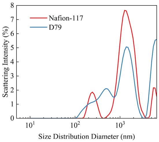
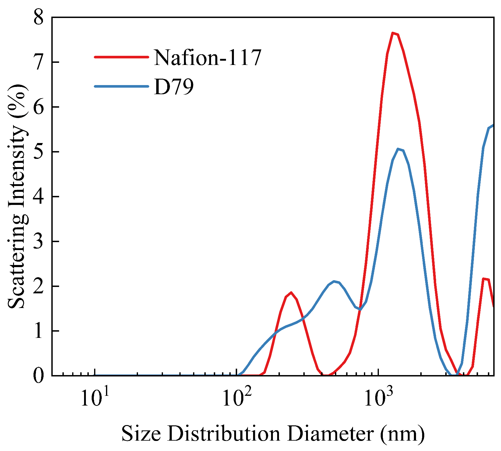
As shown in Figure 1, the catalyst inks prepared with Nafion-117 and D79 ionomers exhibit distinctly different particle size distribution characteristics, indicating that the particles and aggregates in the two inks have different hydrodynamic size distributions. For consistency, the particle-size distribution shown in the figure and the corresponding parameters listed in Table 1 were obtained from the same measurement. The mean particle sizes of the Nafion-117 and D79 inks are 769.2 and 1076.0 nm, respectively, while their main peak positions are 969.4 and 1052.7 nm, respectively, confirming the difference. The particle size distribution of the Nafion-117 ink is mainly concentrated within a relatively limited size range while still exhibiting a certain distribution width, suggesting a relatively uniform hydrodynamic size of the particles and aggregates in the ink. In contrast, the D79 ink exhibits a broader multimodal particle size distribution, indicating the coexistence of particles or aggregates with different characteristic sizes and, consequently, a wider overall range of hydrodynamic sizes. The differences in particle size distributions suggest that the catalyst inks based on the two ionomers exhibit different aggregation states, which may be related to the intrinsic structures of the ionomers and their distribution within the inks. It should be noted that the DLS results are intended to provide a qualitative comparison of the particle-size distribution characteristics of the two catalyst inks.
Figure 1.
Hydrodynamic size distributions obtained by DLS.
Table 1.
Representative DLS results of catalyst inks prepared with Nafion-117 and D79 ionomers.
The differences in particle size distributions may be associated with the microstructural characteristics of the resulting catalyst layers. However, the final morphology and pore structure may also be influenced by solvent evaporation, particle rearrangement, and shrinkage during drying and film formation. Therefore, the observed differences in particle size distributions provide a basis for further investigating the surface morphology and pore structure of the catalyst layers, rather than establishing a direct causal relationship.
3.2. Effect of Ionomer Side-Chain Length on CL Microstructure
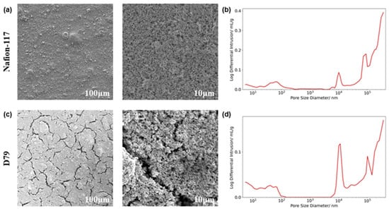
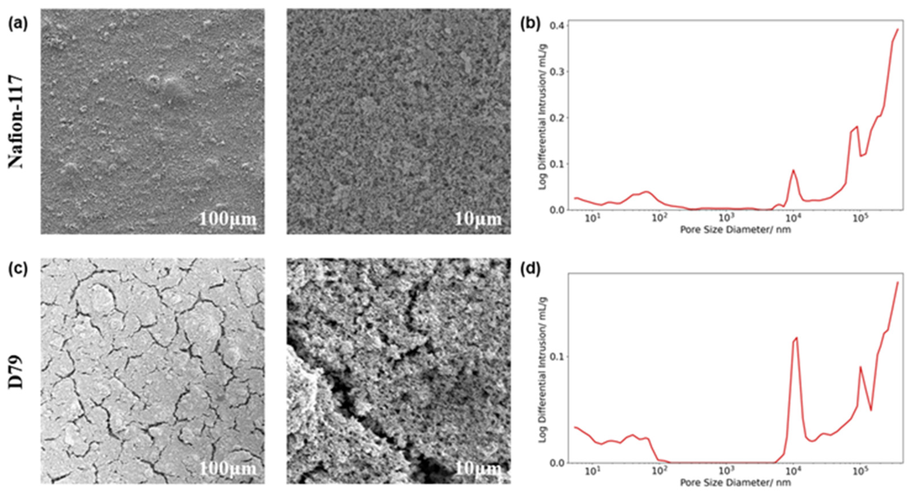
The surface morphology of the CL in the MEA prepared with Nafion-117 ionomer is shown in Figure 2a. At low magnification, the Nafion-117 catalyst layer exhibits a relatively flat and continuous surface, with no obvious macroscopic cracks or large-area structural defects observed, indicating that this ionomer system can form a relatively uniform catalyst-layer coverage. With increasing magnification, the catalyst layer is observed to consist mainly of nanoscale particles and their agglomerates, with relatively dense packing between particles and the formation of interparticle pores within a certain size range. From a microstructural perspective, this dense particle packing is conducive to maintaining continuous contact between catalyst particles while providing space for ionomer distribution and reactant transport. However, the relatively compact particle arrangement may also reduce the openness of the pore network within the catalyst layer, thereby imposing some influence on gas diffusion and product-water transport, particularly under near-boiling-point operation at high current densities, where continuously generated water may further increase local mass-transfer resistance. As shown by the MIP results in Figure 2b, the Nafion-117 CL exhibits a distinct multiscale pore-size distribution, indicating the formation of a heterogeneous pore structure spanning the nano- to micrometer scale. The Nafion-117 system exhibits a pore-size distribution peak around 104 nm, together with a gradually increasing mercury intrusion response at larger pore sizes, suggesting the presence of a certain proportion of micrometer-scale pores within the catalyst layer. However, combined with the SEM results, the overall structure remains dominated by relatively dense particle packing, and the pore structure may mainly originate from interparticle gaps, with some pores exhibiting relatively limited accessibility.
Figure 2.
SEM images of CL based on (a) Nafion-117 and (c) D79; MIP pore size distributions of CL based on (b) Nafion-117 and (d) D79.
In contrast, the CL prepared with D79 ionomer exhibits distinctly different surface morphological characteristics, as shown in Figure 2c. At low magnification, numerous widely distributed cracks can be observed on the surface of the D79 catalyst layer, with a certain degree of interconnection. Compared with the continuous and relatively flat surface of the Nafion-117 catalyst layer, the D79 catalyst layer exhibits more pronounced surface undulations and structural heterogeneity. These cracks may be associated with volumetric shrinkage during the drying and film-forming process of the catalyst layer. Although cracks may potentially facilitate gas transport by providing additional pathways, excessive cracking could compromise the mechanical integrity of the catalyst layer, weaken interfacial contact within the catalyst layer or between the catalyst layer and adjacent components, and increase the risk of structural degradation during long-term operation. However, the present study focuses on the initial morphology and electrochemical performance, and the effects of these cracks on interfacial contact and long-term durability have not been directly evaluated. During solvent evaporation, structural rearrangement between the ionomer and catalyst particles may induce local shrinkage stresses, thereby contributing to crack formation. However, the specific role of the drying process requires further investigation. At higher magnification, the D79 catalyst layer is also found to consist of nanoscale particles and their agglomerates. However, compared with the Nafion-117 system, the particles exhibit looser packing, higher surface roughness, and more pronounced interparticle pore structures. As shown in Figure 2d, the D79 CL also exhibits a multiscale pore size distribution ranging from nanometer to micrometer scales. Compared with Nafion-117, the D79 system presents a more pronounced and sharper pore distribution peak around ~104 nm, indicating that pores within this size range make a more significant contribution to the overall pore volume. Combined with the SEM results, the looser particle packing and crack structures in the D79 CL show a certain correspondence with its pore-size distribution, indicating that the two ionomer systems form different CL microstructures. This difference may be associated with the distinct side-chain architectures of the ionomers. Compared with Nafion-117, the shorter side chains of D79 may modify ionomer chain conformation and its interaction with catalyst particles during ink preparation and catalyst-layer formation, thereby affecting particle rearrangement and contributing to the formation of a looser particle network and more pronounced interparticle pore structures. However, further direct characterization of ionomer distribution within the catalyst layer is required to verify this hypothesis.
Quantitative analysis of the MIP results further reveals differences in the pore structures of the two catalyst layers. The Nafion-117 catalyst layer exhibits a total intrusion volume of 0.2290 mL g−1 and a porosity of 28.0%, compared with 0.1351 mL g−1 and 18.9%, respectively, for the D79 catalyst layer. In contrast, D79 exhibits a larger total pore area (7.333 m2 g−1) than Nafion-117 (6.019 m2 g−1), together with a smaller average pore diameter (73.68 nm versus 152.21 nm). These results indicate that the two catalyst layers differ not only in their total mercury-accessible pore volume but also in their pore-size characteristics. The larger pore area and smaller average pore diameter of D79 suggest a greater contribution from relatively small pores or pore throats.
Overall, the two ionomer systems exhibit distinct catalyst-ink particle size distributions and catalyst-layer microstructural characteristics. The Nafion-117 system forms a catalyst layer with relatively dense particle packing and a comparatively continuous surface, whereas the D79 system exhibits looser particle packing, more pronounced surface cracks, and distinct pore-size distribution characteristics. The broader multimodal particle size distribution of the D79 ink may be related to the microstructural differences observed in the resulting catalyst layer. However, catalyst-layer formation also involves solvent evaporation, particle rearrangement, and shrinkage. These microstructural differences may influence reactant transport and water distribution within the catalyst layer and may be associated with the differences in electrochemical performance discussed below.
3.3. Effect of Temperature on Proton Transport Behavior
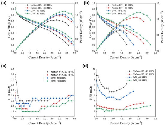
To investigate the influence of catalyst-layer ionomer structures on MEA performance under near-boiling-point conditions, the polarization performance and high-frequency resistance (HFR) characteristics of Nafion-117 and D79 MEAs were evaluated at 75 and 105 °C under different RH conditions (RH 40% and 80%). As shown in Figure 3, both ionomer systems exhibit pronounced humidity-dependent behavior; however, distinct performance degradation characteristics are observed under high-temperature and low-humidity conditions.
Figure 3.
Polarization curves of MEAs at (a) 75 °C and (b) 105 °C and corresponding HFR curves at (c) 75 °C and (d) 105 °C under different RH conditions.
As shown in Figure 3a, both Nafion-117- and D79-based MEAs exhibited favorable electrochemical performance at 75 °C. The performance was improved with increasing RH. For the Nafion-117 MEA, the limiting current density and peak power density under RH 40% were lower than those under RH 80%. This behavior may be attributed to the insufficient water content in CL under low-humidity conditions. The reduced hydration level could decrease the dissociation of sulfonic acid groups in the LSC ionomer, thereby affecting the formation of proton-conducting pathways. In addition, the reduced water availability may decrease the effective TPB area and increase the electrochemical polarization losses. When the RH was increased to 80%, the peak power density of the Nafion-117 MEA increased to 1.49 W∙cm−2, representing an improvement of approximately 15%. This result indicates that sufficient hydration can facilitate proton transport and improve the overall polarization performance of the MEA. In comparison, the D79-based MEA exhibited higher output performance than Nafion-117 under both humidity conditions. This behavior may be related to the structural characteristics of SSC ionomers. The SSC ionomer may form more continuous proton transport pathways under low-humidity conditions and maintain better proton conductivity with limited water availability.
As shown in Figure 3c, both MEAs exhibited relatively low HFR values at 75 °C. Under RH 80%, Nafion-117 and D79 maintained lower HFR values in the low-to-medium current-density region, suggesting that sufficient humidification enabled the formation of stable proton-conducting networks in both ionomers. With increasing current density, a slight increase in HFR was observed. This phenomenon may be associated with water redistribution in CL during high-current-density operation.
As shown in Figure 3b, the performance of both Nafion-117 and D79 decreased at 105 °C, while the extent of degradation was different. The Nafion-117 MEA exhibited the most severe performance loss under RH 40%. The limiting current density was below 2 A∙cm−2, and the peak power density decreased to only 0.65 W∙cm−2. Although the performance was partially recovered by increasing RH, significant polarization losses remained. These results suggest that Nafion-117 suffers from stronger water management limitations under near-boiling-point operating conditions. This behavior may be associated with its LSC structure, which requires sufficient hydration to maintain continuous proton-conducting pathways. At elevated temperatures, accelerated water evaporation may induce local dehydration in CL, resulting in increased proton transport resistance. In addition, dehydration may alter the hydrated morphology of the ionomer, leading to shrinkage of ionomer domains and reduced contact between ionomer and catalyst surfaces. Meanwhile, dehydration-induced morphological changes in the ionomer may alter the catalyst-layer microstructure and the catalyst–ionomer interface, which could further contribute to mass transport limitations at high current densities. In contrast, the D79-based MEA exhibited better performance retention under near-boiling-point conditions. At 105 °C and 80% RH, the D79-based MEA achieved a peak power density of approximately 1.21 W∙cm−2. Although this value was lower than that obtained at 75 °C (1.66 W∙cm−2), it remained higher than that of the Nafion-117-based MEA under the same operating condition (1.06 W∙cm−2). This performance trend suggests that although elevated temperature still induces negative effects, such as accelerated water loss and increased transport resistance, the SSC structure of D79 may facilitate the preservation of proton-conducting pathways and maintain more effective catalyst–ionomer contact, thereby mitigating performance degradation at near-boiling-point temperatures.
The HFR results in Figure 3d further support this observation. At 105 °C, Nafion-117 exhibited significantly increased resistance and maintained higher HFR values throughout the operation. In comparison, D79 maintained relatively lower HFR values under both RH conditions. This difference may be associated with variations in proton transport within the membrane and catalyst layers, as well as interfacial contact resistance. The SSC structure may also contribute to more favorable water management under near-boiling-point conditions; however, this possibility cannot be directly confirmed by HFR measurements alone.
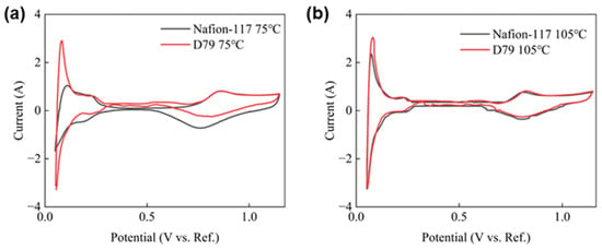
As shown in Figure 4 and Table 2, both MEAs exhibited typical redox features of Pt catalysts. This result indicates that the Pt catalysts retained good electrochemical activity in both ionomer systems. At 75 °C, the ECSA values of Nafion-117 and D79 were 28.90 and 36.57 , respectively. The ECSA of D79 was approximately 26.5% higher than that of Nafion-117. This improvement may suggest that the SSC structure provides a more favorable ionomer–catalyst interface, thereby enhancing the electrochemical accessibility of Pt active sites. In comparison, the LSC structure may result in less favorable ionomer–catalyst interactions, thereby limiting the utilization of some Pt active sites.
Figure 4.
CV of MEAs with different ionomers at (a) 75 and (b) 105 °C.
Table 2.
ECSA of MEAs with different ionomers at 75 and 105 °C.
When the operating temperature was increased to 105 °C, the ECSA values of both MEAs decreased to different extents. The ECSA of Nafion-117 decreased to 25.23 , corresponding to a retention of 87.3%. For D79, the ECSA decreased to 28.05 , with a retention of 76.7%. The decrease in ECSA may be associated with enhanced water evaporation under near-boiling-point conditions, which reduces ionomer hydration and may impair proton transport within the CL. Notably, although D79 showed a larger relative decrease in ECSA than Nafion-117, it still maintained a higher absolute ECSA at 105 °C. It indicates that more Pt active sites remained electrochemically accessible in the D79-based MEA under near-boiling-point conditions. Combined with the polarization results, the higher performance of D79 at near-boiling-point temperatures may not originate solely from its higher ECSA, but may also be associated with improved mass transport and water management in CL.
The difference in ECSA retention may reflect the temperature-dependent changes in the electrochemical accessibility of Pt active sites in the two ionomer systems. The initially higher ECSA of D79 suggests that a larger Pt surface area was electrochemically accessible at 75 °C. However, as the temperature increases, enhanced water evaporation may alter ionomer hydration and proton access to the catalyst surface, potentially reducing the accessibility of some Pt sites and contributing to the larger relative ECSA decrease observed for D79. Differences in the ionomer–catalyst interface and catalyst-layer morphology may also contribute to this behavior, although these effects cannot be distinguished based on the ECSA measurements alone. Importantly, the higher absolute ECSA of D79 at 105 °C, together with its lower HFR and higher limiting current density, suggests that the retention of electrochemically accessible Pt sites, ohmic resistance, and reactant transport jointly influence the overall cell performance. Thus, despite its lower relative ECSA retention, D79 may maintain superior cell performance because its remaining accessible Pt surface area and transport characteristics are more favorable under near-boiling-point conditions.
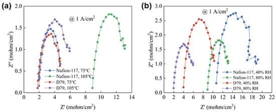
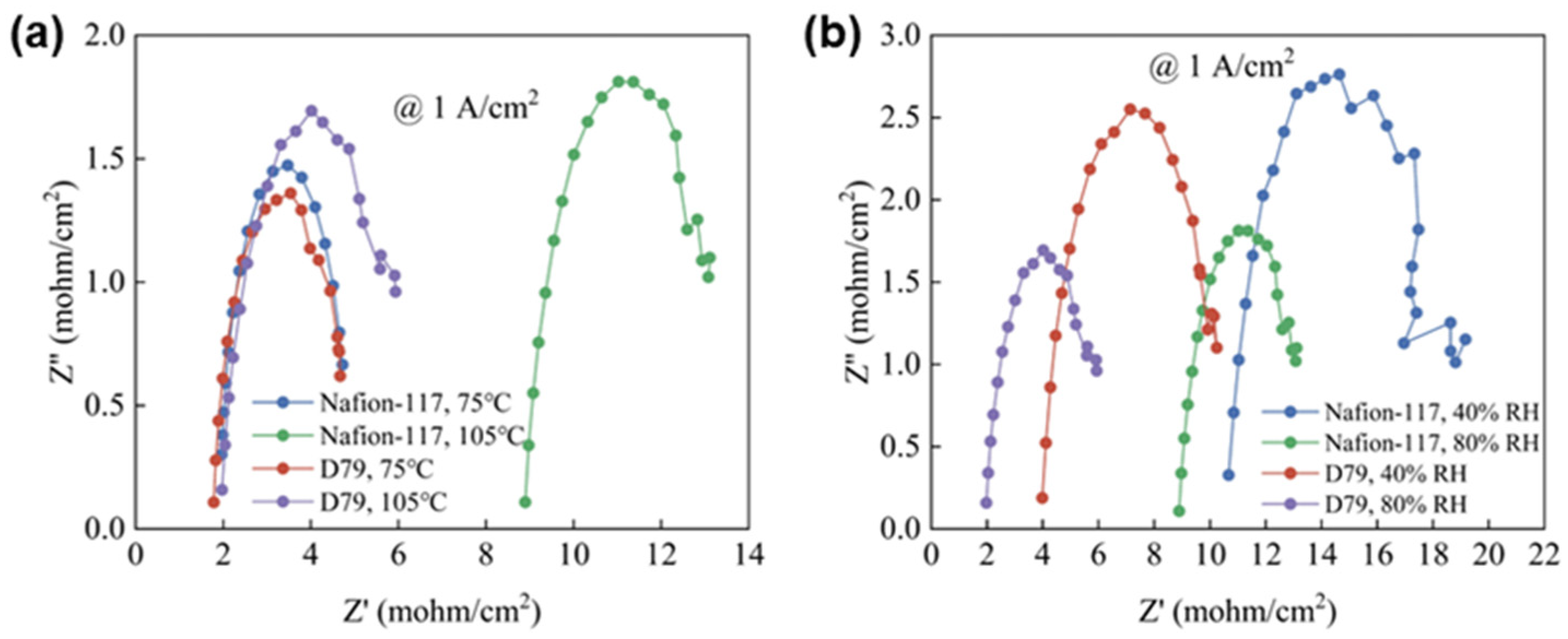
To further investigate proton transport and electrochemical reaction processes within catalyst layers containing different ionomers, EIS measurements were performed and fitted, with the results shown in Figure 5 and Table 3. Figure 5a compares the effects of temperature on the impedance characteristics of MEA with different ionomers under RH 80% conditions. It can be observed that Nafion-117 and D79 exhibit similar impedance responses at 75 °C. The fitting results show that the Rs and Rct values of Nafion-117 are 1.934 and 2.949 mΩ∙cm−2, respectively, while those of D79 are 1.862 and 2.852 mΩ∙cm−2. These results indicate that both ionomer systems can maintain sufficient hydration and establish effective proton transport pathways and catalytic interfaces under highly humidified conditions.
Figure 5.
EIS of MEA prepared with different ionomers under different operating conditions: (a) temperature effect at 80% RH; (b) humidity effect at 105 °C.
Table 3.
EIS fitting parameters of MEAs with different ionomers at different temperatures and RH%.
However, when the temperature increases to 105 °C, the two ionomer systems exhibit distinctly different impedance evolution behaviors. Specifically, the Rs and Rct values of Nafion-117 increase to 9.115 and 3.969 mΩ∙cm−2, corresponding to increases of 371% and 34.6%, respectively. This result suggests that the proton transport process in the Nafion-117 MEA is significantly affected under near-boiling-point operating conditions. Since proton transport in Nafion strongly relies on continuous hydration networks, elevated temperature may accelerate water evaporation in CL, causing shrinkage or disruption of hydrophilic ion-conducting channels and consequently increasing proton transport resistance. In contrast, D79 exhibits much smaller impedance variations with increasing temperature. Under RH 80% conditions, the Rs and Rct values of D79 increase only to 2.116 and 3.651 mΩ∙cm−2, corresponding to increases of 13.6% and 28.0%, respectively, indicating a more stable impedance response. In particular, the increase in ohmic resistance is significantly lower than that of Nafion-117, suggesting that the D79 ionomer structure is more capable of maintaining continuous proton transport pathways under elevated temperature conditions. This behavior may be associated with the enhanced stability of hydrophilic domains induced by the shorter side-chain structure of D79, enabling more stable proton transport under near-boiling-point conditions.
The influence of humidity variation on impedance behavior at 105 °C was further analyzed, as shown in Figure 5b. With increasing RH from 40% to 80%, both ionomer systems exhibit reduced impedance values, indicating that enhanced water supply facilitates proton transport and electrochemical reaction processes under elevated temperature conditions. However, the responses of different ionomers to humidity variation are significantly different. Under RH 40% conditions at 105 °C, Nafion-117 exhibits a relatively high ohmic resistance. This behavior may be attributed to insufficient hydration of the ionomer under the combined effects of elevated temperature and low humidity, which may disrupt the continuity of proton-conducting pathways and increase the resistance to proton transport. Although both Rs and Rct decrease with increasing RH, the reductions remain limited, suggesting that increasing humidity alone is insufficient to fully recover the proton transport characteristics under near-boiling-point conditions.
In comparison, D79 exhibits greater tolerance to humidity variations at 105 °C. Under RH 40% conditions, the Rs and Rct t values of D79 are 4.273 and 5.694 mΩ∙cm−2, respectively. After increasing RH to 80%, the Rs and Rct values further decrease to 2.116 and 3.651 mΩ∙cm−2, respectively. Notably, under low-humidity conditions, D79 maintains a substantially lower ohmic resistance than Nafion-117, indicating that its proton transport structure exhibits stronger tolerance toward water content fluctuations.
The EIS results demonstrate that ionomer side-chain structures significantly influence the impedance response of MEAs under near-boiling-point conditions. For Nafion-117, the decreased stability of hydration networks at elevated temperatures leads to a rapid increase in proton transport resistance. In contrast, D79 maintains more stable proton transport characteristics under both elevated temperature and varying humidity conditions, exhibiting improved temperature and humidity adaptability. These results are consistent with the DLS, SEM, and MIP analyses, which revealed a more open transport structure for D79, further highlighting the importance of ionomer structure optimization in improving transport processes in near-boiling-point PEMFCs.
3.4. Polarization Loss Analysis Under Near-Boiling-Point Conditions
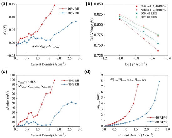
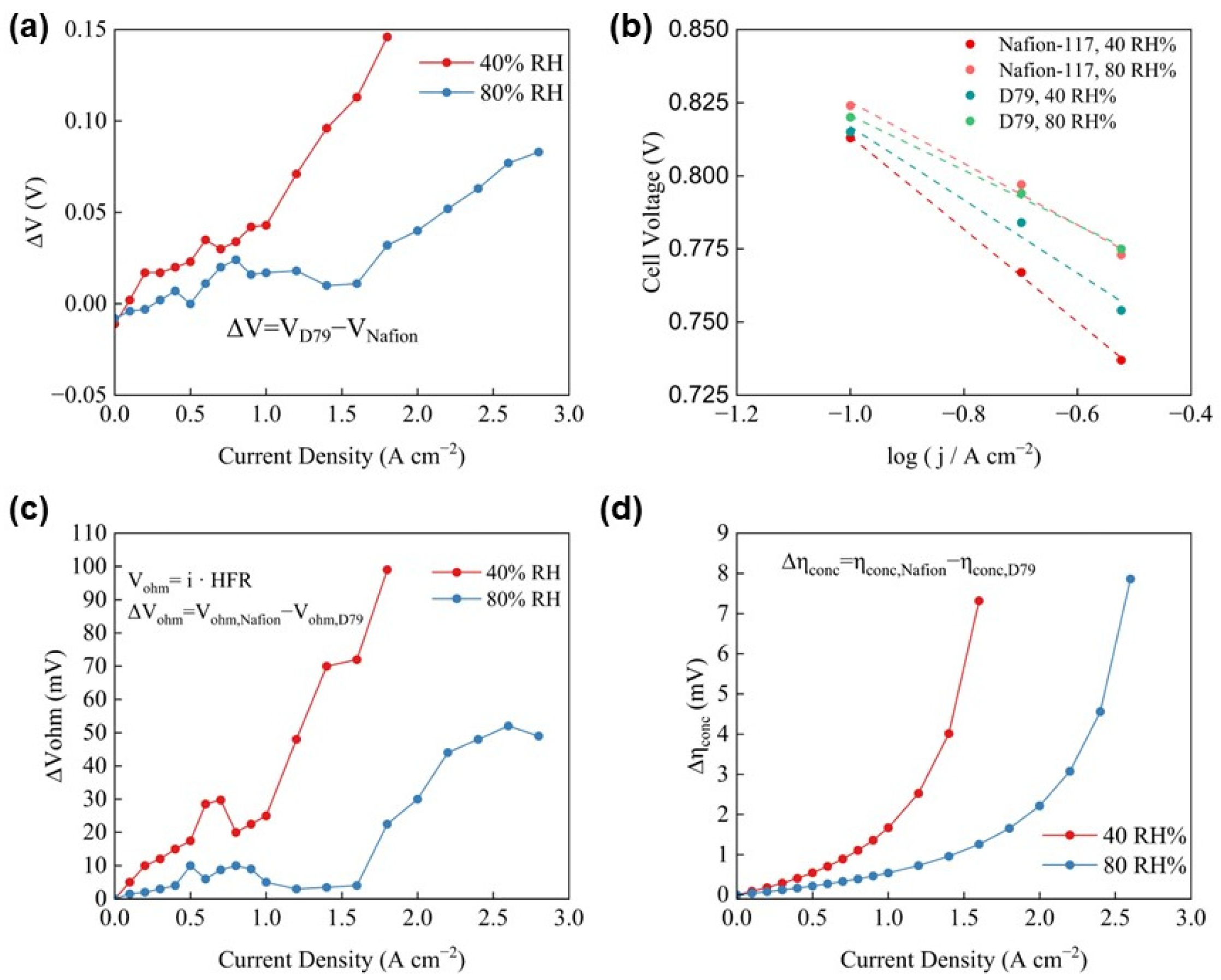
To further elucidate the mechanisms governing performance losses associated with different ionomers under near-boiling-point operating conditions, the polarization losses originating from different processes were quantitatively separated based on the polarization curves obtained at 105 °C. Figure 6a presents the voltage difference (ΔV) between the D79 and Nafion-117 MEA at 105 °C, where ΔV is defined as the voltage difference between D79 and Nafion-117 at the same current density. It can be observed that ΔV exhibits a pronounced current-density dependence under different RH conditions. Under RH 40% conditions, the voltage difference between the two MEAs remains relatively small in the low-current-density region, whereas the voltage advantage of D79 increases rapidly with increasing current density. Similarly, under RH 80% conditions, D79 maintains a higher voltage output and exhibits a more pronounced advantage in the high-current-density region. These results suggest that the performance enhancement of D79 is not primarily associated with electrochemical reaction processes under low-load conditions but is more closely related to the improved transport of reactants, water, and protons in CL under high-current-density operation.
Figure 6.
Polarization loss analysis of Nafion-117 and D79 MEAs under near-boiling-point conditions: (a) voltage difference; (b) Tafel curves; (c) ohmic loss difference; (d) concentration overpotential difference as a function of current density.
To distinguish the contribution of electrochemical kinetics to the performance difference, Tafel analysis was further conducted for the MEAs with different ionomers at 105 °C, as shown in Figure 6b, and the corresponding fitting parameters are summarized in Table 4. The Tafel slopes were obtained by linear fitting of the approximately linear regions of the Tafel plots over a current-density range of 0.1~0.3 A cm−2, where the polarization response was predominantly activation-controlled. The selected fitting regions were identified based on the linearity of the Tafel plots, while regions potentially affected by substantial ohmic and mass-transport losses were excluded.
Table 4.
Comparison of Tafel fitting parameters for Nafion-117 and D79 MEAs at 105 °C.
The results show that the Tafel slopes of both ionomer systems decrease with increasing RH, indicating that enhanced humidification improves the hydration state of the catalyst layer and reduces polarization losses associated with interfacial electrochemical reactions. Under RH 40% conditions, the Tafel slopes of Nafion-117 and D79 are 158.6 and 125.2 mV/dec, respectively, with D79 exhibiting a more favorable kinetic response. Under RH 80% conditions, the Tafel slopes decrease to 105.0 and 93.5 mV/dec, respectively, and the difference between the two systems becomes less pronounced. These results indicate that under near-boiling-point and low-humidity conditions, D79 is more capable of maintaining a stable proton transport environment and interfacial hydration state in the catalyst layer, thereby reducing activation polarization associated with deterioration of the reaction interface. In comparison, the reduced water retention capability of Nafion-117 may lead to more pronounced changes at the catalyst/ionomer interface, resulting in a larger Tafel slope. Therefore, the lower Tafel slope of D79 is likely attributed to the more open catalyst-layer microenvironment rather than a simple enhancement of the intrinsic reaction kinetics.
The difference in ohmic polarization losses between the two MEAs was calculated from the HFR data shown in Figure 3d, and the results are presented in Figure 6c. It can be observed that D79 exhibits lower ohmic polarization losses than Nafion-117 under both RH conditions, and the difference between the two systems gradually increases with increasing current density. Under RH 40% conditions, the ohmic loss of Nafion-117 increases rapidly with increasing current density, whereas D79 exhibits a relatively moderate increase. As the current density increases, the difference in ohmic losses between Nafion-117 and D79 becomes increasingly significant, indicating that proton transport resistance within Nafion-117 increases more substantially under high-load operation. This result is consistent with the previous EIS analysis.
By gradually increasing the current density, the operational limiting current density (iL,op) was determined when the cell voltage decreased to approximately 0.3 V and the cell could no longer maintain stable operation upon further current increase. This operational criterion was adopted to consistently compare the high-current-density performance and transport-related limitations of different MEAs. The corresponding operational limiting current densities are summarized in Table 5.
Table 5.
Comparison of experimental iLs for Nafion-117 and D79 MEAs at 105 °C.
Although the operational limiting current density determined using a voltage cutoff is not strictly equivalent to the true diffusion-limited current density, it can serve as an approximate effective limiting-current parameter for comparative analysis under consistent operating and testing conditions. At high current densities, mass transport limitations become increasingly important, and the rapid voltage decrease provides an operational indication of the onset of severe performance limitations. In this study, the same voltage criterion and testing procedure were applied to all MEAs, allowing their high-current-density behavior to be compared consistently. Accordingly, the measured operational limiting current density was used as an approximation of the effective limiting current in Equation (4) to estimate the relative differences in concentration-related polarization. This approximation is intended for comparative analysis and does not imply that the measured current represents a strictly diffusion-controlled limit.
The concentration overpotential was calculated according to Equation (4) [33], and the difference in concentration polarization losses between Nafion-117 and D79 as a function of current density was obtained as shown in Figure 6d. It can be observed that D79 exhibits superior mass transport capability at 105 °C, with a more pronounced performance advantage under low-humidity conditions. This result indicates that D79 exhibits a more favorable high-current-density performance under near-boiling-point conditions, particularly under low-humidity operation. The improved operational limiting current density may be associated with the more open catalyst-layer structure and enhanced transport characteristics of D79, which could alleviate transport-related polarization losses under demanding operating conditions.
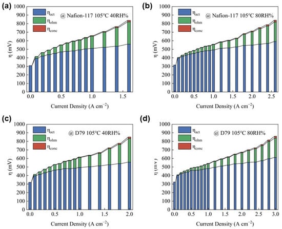
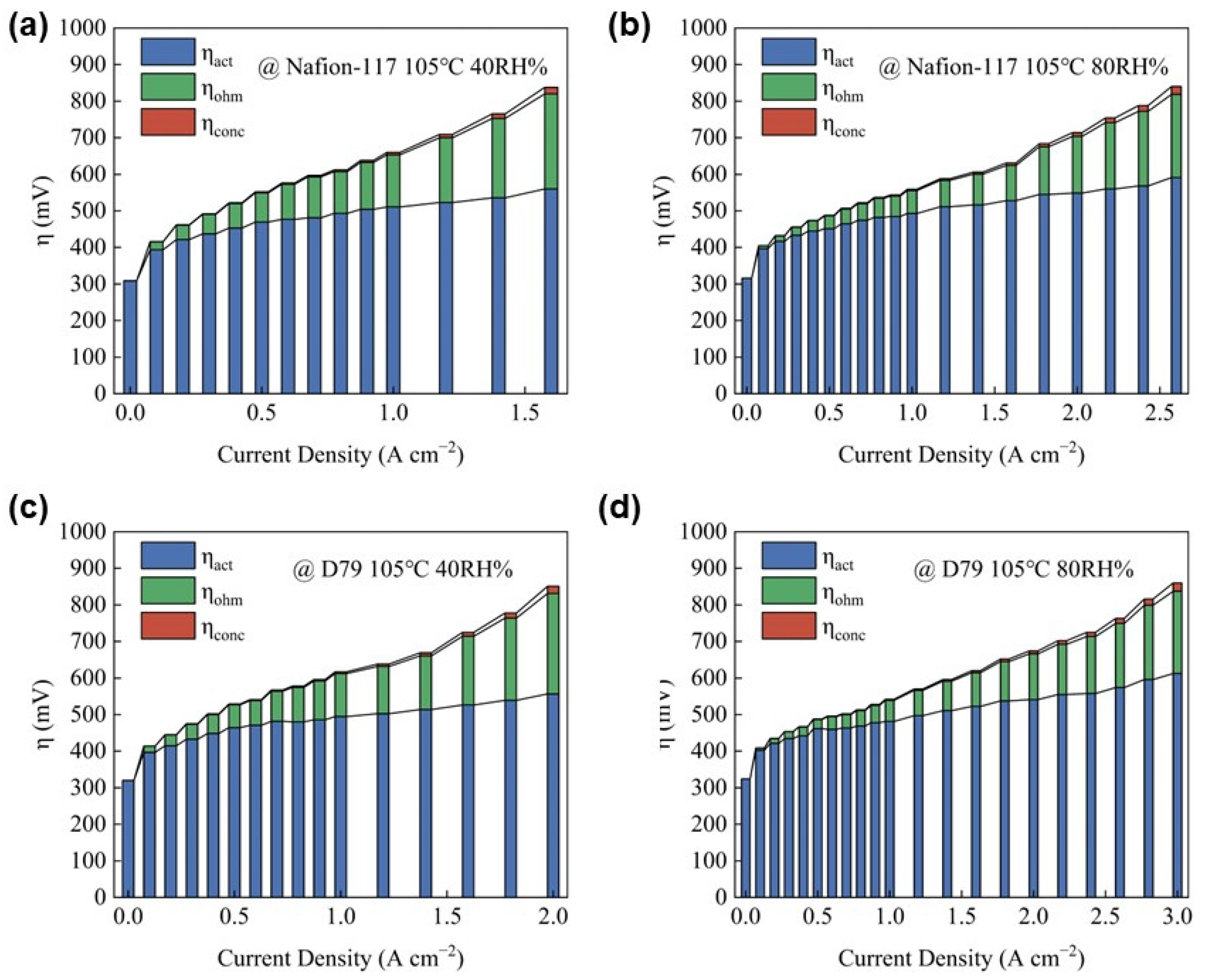
Finally, based on Vcell = E − ηact − ηohm − ηconc, the activation overpotential (ηact) at each current density point was calculated, and the polarization losses of Nafion-117 and D79 MEAs at 105 °C were further decomposed, as shown in Figure 7. Overall, both ionomer-based MEAs exhibit typical polarization loss evolution characteristics under different operating conditions. In the low-current-density region, activation polarization dominates the total voltage loss. With increasing current density, ohmic polarization gradually increases and becomes an important factor limiting cell performance. At higher current densities, concentration polarization increases rapidly, indicating that reactant transport gradually becomes the critical limiting factor for PEMFC performance.
Figure 7.
Voltage loss decomposition of Nafion-117 and D79 MEAs under near-boiling-point conditions: Nafion-117-based MEA at (a) 40% RH and (b) 80% RH; D79-based MEA at (c) 40% RH and (d) 80% RH.
As shown in Figure 7a,b, increasing RH can partially reduce the ohmic polarization loss of the Nafion-117 MEA in the medium- to high-current-density region. Compared with RH 80%, Nafion-117 under RH 40% exhibits a more pronounced increase in ohmic loss at medium-to-high current densities, resulting in a larger voltage penalty at high current density. This indicates that proton transport in CL of Nafion-117 is significantly restricted under near-boiling-point and low-humidity conditions. Since proton conduction in Nafion relies strongly on continuous hydration networks, water evaporation at elevated temperatures may reduce the water content of the ionomer phase, leading to contraction or decreased connectivity of proton-conducting pathways and consequently increasing proton transport resistance within the catalyst layer and membrane. When RH is increased to 80%, the enhanced water supply partially restores the hydration state of the ionomer phase and reduces the ohmic loss associated with proton transport.
In contrast, D79 exhibits a more stable ohmic polarization behavior under different humidity conditions, as shown in Figure 7c. Even under low-humidity conditions (RH 40%), the increase in ohmic loss of D79 remains lower than that of Nafion-117, indicating that D79 can maintain more stable proton transport capability under elevated temperature and insufficient hydration conditions. When RH is increased to 80% (Figure 7d), the ohmic polarization of D79 is further reduced; however, the improvement is relatively limited, suggesting that the D79 ionomer structure possesses enhanced water retention capability and temperature adaptability. Combined with the previous EIS results, D79 exhibits a lower Rs value at 105 °C, further demonstrating its ability to effectively reduce ohmic losses associated with proton transport limitations under near-boiling-point operation. Since the cell configuration, PEM, gas diffusion layers, and assembly conditions were identical, the difference in ohmic polarization between the two ionomers primarily originates from differences in proton transport capability and hydration stability of the ionomer phase in CL. Therefore, Figure 7 provides indirect evidence for the proton transport characteristics and humidity dependence of the two ionomer systems from the perspective of cell-level performance.
At high current densities, both MEAs exhibit an increasing contribution from concentration polarization, indicating that transport-related losses become more important as the reaction rate increases. Based on the slope change in the concentration polarization curves, the mass transport-limited region becomes apparent at approximately 1.0 A cm−2 for Nafion-117 at 40% RH, while it is extended to higher current densities for the other operating conditions, including approximately 1.6 A cm−2 for Nafion-117 at 80% RH, 1.4 A cm−2 for D79 at 40% RH, and 2.4 A cm−2 for D79 at 80% RH. Under RH 40% conditions, Nafion-117 enters the mass transport-limited region at a lower current density, indicating more severe transport limitations compared with D79. In comparison, D79 exhibits a relatively slower increase in concentration polarization under both RH 40% and RH 80% conditions, suggesting improved mass transport behavior at high current densities. This observation is consistent with the SEM and MIP results, which reveal a more open catalyst-layer morphology and a distinct multiscale pore structure in the D79-based catalyst layer. These structural features may provide favorable pathways for reactant transport and product-water removal, potentially contributing to the reduced concentration polarization observed under near-boiling-point conditions.
Overall, the performance degradation of MEAs at 105 °C results from the combined effects of activation, ohmic, and concentration polarization losses, among which ionomer structures exert a more pronounced influence on ohmic and mass transport losses. For Nafion-117, reduced hydration network stability at elevated temperatures leads to increased proton transport resistance, particularly under low-humidity conditions. In contrast, D79 maintains more favorable transport characteristics under elevated temperature and varying humidity conditions, which may be attributed to its enhanced ionomer hydration stability and more accessible catalyst-layer pore structure. Therefore, for near-boiling-point PEMFC operation, ionomer design should not only focus on achieving high proton conductivity but also consider water retention capability at elevated temperatures and the ability to regulate CL microstructures, thereby enabling synergistic optimization of proton transport, reactant diffusion, and water management.
For a more direct comparison, the key electrochemical performance parameters of the Nafion-117 and D79 MEAs at 105 °C are summarized in Table 6.
Table 6.
Summary of electrochemical performance for Nafion-117 and D79 MEAs at 105 °C
4. Conclusions
This study investigated the effects of PFSA ionomer side-chain length on catalyst-layer structure, electrochemical performance, and transport-related polarization in PEMFCs under near-boiling-point conditions. The main conclusions are summarized as follows:
- (1)
- Ionomer side-chain structure influences catalyst ink aggregation and catalyst-layer pore morphology. Compared with Nafion-117, D79 exhibits a broader particle-size distribution in the catalyst ink and a more open catalyst-layer morphology, with a more pronounced pore-size distribution peak around 104 nm. These results suggest that differences in ionomer–catalyst interactions and aggregate packing may influence the formation of multiscale pore structures, potentially affecting reactant transport and product-water removal.
- (2)
- D79 exhibits more favorable electrochemical performance and transport-related behavior, particularly at elevated temperature and low humidity. At 105 °C and 40% RH, D79 shows lower resistances than Nafion-117. D79 also exhibits higher ECSA at both 75 and 105 °C, indicating greater electrochemically active surface-area utilization. In addition, its operational limiting current density reaches 2.2 A cm−2 at 105 °C and 40% RH, compared with 1.8 A cm−2 for Nafion-117. Polarization-loss analysis further indicates that the performance difference is associated with the combined effects of activation, ohmic, and concentration polarization, with transport-related losses becoming increasingly important at high current densities.
Overall, the superior performance of D79 under near-boiling-point conditions is associated with not only higher Pt utilization but also more favorable proton transport characteristics and a more open catalyst-layer architecture. These findings highlight that the side-chain structure of PFSA ionomers influences electrochemical processes in the catalyst layer and may affect gas and water transport by modifying catalyst ink dispersion and the resulting pore structure. Therefore, PFSA ionomer design should consider the interplay between molecular structure, catalyst-layer microstructure, and electrochemical performance to achieve a favorable balance between reaction-site utilization and transport properties under elevated-temperature and low-humidity conditions.
Author Contributions
J.F. prepared the original draft of the manuscript. J.W. and B.L. conceived the research and provided critical feedback. P.M. and W.Z. contributed to the conceptualization of the study, experimental design, and data analysis. D.Y. and C.Z. contributed to the interpretation of the results and project administration. All authors have read and agreed to the published version of the manuscript.
Funding
This research was funded by the National Key R&D Program of China (No. 2022YFB4003505).
Data Availability Statement
The research data are available upon request.
Conflicts of Interest
The authors declare no conflicts of interest.
Abbreviations
The following abbreviations are used in this manuscript:
| PEMFC | Proton-Exchange Membrane Fuel Cell |
| CL | Catalyst Layer |
| LSC | Long Side Chain |
| SSC | Short Side Chain |
| MEA | Membrane Electrode Assembly |
| RH | Relative Humidity |
References
- Yu, J.; Hu, K.; Zhang, Z.; Luo, L.; Liu, Y.; Zhou, D.; Wang, F.; Kuang, Y.; Xu, H.; Li, H.; et al. Interfacial Nanobubbles’ Growth at the Initial Stage of Electrocatalytic Hydrogen Evolution. Energy Environ. Sci. 2023, 16, 2068–2079. [Google Scholar] [CrossRef] [Scilit]
- Doulgeris, S.; Dimaratos, A.; Zacharof, N.; Toumasatos, Z.; Kolokotronis, D.; Samaras, Z. Real World Fuel Consumption Prediction via a Combined Experimental and Modeling Technique. Sci. Total Environ. 2020, 734, 139254. [Google Scholar] [CrossRef] [Scilit]
- Fan, L.; Wang, J.; Ruiz Diaz, D.F.; Li, L.; Wang, Y.; Jiao, K. Molecular Dynamics Modeling in Catalyst Layer Development for PEM Fuel Cell. Prog. Energy Combust. Sci. 2025, 108, 101220. [Google Scholar] [CrossRef] [Scilit]
- Yoshizumi, T.; Kubo, H.; Okumura, M. Development of High-Performance FC Stack for the New MIRAI; SAE International: Warrendale, PA, USA, 2021. [Google Scholar]
- Bose, A.B.; Gopu, S.; Li, W. Enhancement of Proton Exchange Membrane Fuel Cells Performance at Elevated Temperatures and Lower Humidities by Incorporating Immobilized Phosphotungstic Acid in Electrodes. J. Power Sources 2014, 263, 217–222. [Google Scholar] [CrossRef] [Scilit]
- Li, J.; Bu, F.; Ru, C.; Jiang, H.; Duan, Y.; Sun, Y.; Pu, X.; Shang, L.; Li, X.; Zhao, C. Enhancing the Selectivity of Nafion Membrane by Incorporating a Novel Functional Skeleton Molecule to Improve the Performance of Direct Methanol Fuel Cells. J. Mater. Chem. A 2020, 8, 196–206. [Google Scholar] [CrossRef] [Scilit]
- Jiao, K.; Xuan, J.; Du, Q.; Bao, Z.; Xie, B.; Wang, B.; Zhao, Y.; Fan, L.; Wang, H.; Hou, Z.; et al. Designing the next Generation of Proton-Exchange Membrane Fuel Cells. Nat. Int. Wkly. J. Sci. 2021, 595, 361–369. [Google Scholar] [CrossRef] [Scilit]
- Yang, J.; Xu, H.; Li, J.; Gong, K.; Yue, F.; Han, X.; Wu, K.; Shao, P.; Fu, Q.; Zhu, Y.; et al. Oxygen- and Proton-Transporting Open Framework Ionomer for Medium-Temperature Fuel Cells. Science 2024, 385, 1115–1120. [Google Scholar] [CrossRef] [Scilit]
- Singh, B.; Singh, M. Interplay between Structure and Mechanical Relaxations Based on PFSA Proton Conducting Membranes. J. Membr. Sci. 2019, 573, 280–287. [Google Scholar] [CrossRef] [Scilit]
- Ryu, S.; Lee, B.; Kim, J.; Pak, C.; Moon, S. High-temperature Operation of PEMFC Using Pore-filling PTFE/Nafion Composite Membrane Treated with Electric Field. Int. J. Energy Res. 2021, 45, 19136–19146. [Google Scholar] [CrossRef] [Scilit]
- Bevilacqua, N.; Asset, T.; Schmid, M.A.; Markötter, H.; Manke, I.; Atanassov, P.; Zeis, R. Impact of Catalyst Layer Morphology on the Operation of High Temperature PEM Fuel Cells. J. Power Sources Adv. 2021, 7, 100042. [Google Scholar] [CrossRef] [Scilit]
- Luo, D.; Li, M.; Ma, Q.; Wen, G.; Dou, H.; Ren, B.; Liu, Y.; Wang, X.; Shui, L.; Chen, Z. Porous Organic Polymers for Li-Chemistry-Based Batteries: Functionalities and Characterization Studies. Chem. Soc. Rev. 2022, 51, 2917–2938. [Google Scholar] [CrossRef] [Scilit]
- Zuo, P.; Li, Y.; Wang, A.; Tan, R.; Liu, Y.; Liang, X.; Sheng, F.; Tang, G.; Ge, L.; Wu, L.; et al. Sulfonated Microporous Polymer Membranes with Fast and Selective Ion Transport for Electrochemical Energy Conversion and Storage. Angew. Chem.—Int. Ed. 2020, 59, 9564–9573. [Google Scholar] [CrossRef] [Scilit]
- Araya, S.S.; Zhou, F.; Liso, V.; Sahlin, S.L.; Vang, J.R.; Thomas, S.; Gao, X.; Jeppesen, C.; Kaer, S.K. A Comprehensive Review of PBI-Based High Temperature PEM Fuel Cells. Int. J. Hydrogen Energy 2016, 41, 21310–21344. [Google Scholar] [CrossRef] [Scilit]
- Wang, Q.; Lu, J.; Zheng, W.; Li, B.; Zheng, J.P.; Cui, G.; Hao, L.; Ming, P. Dynamic Thermal and Mass Transport in PEM Fuel Cells at Elevated Temperatures and Pressures: A 3D Model Study. Fuel 2025, 381, 133623. [Google Scholar] [CrossRef] [Scilit]
- Yang, D.; Guo, Y.; Zhang, Z.; Wang, J.; Zheng, W.; Yang, D.; Ming, P.; Li, B. Cracking in PEMFC Electrodes with Highly Graphitized Carbon Supports: Effects of Solvent and Dispersion Process. Int. J. Hydrogen Energy 2026, 225, 154539. [Google Scholar] [CrossRef] [Scilit]
- Chen, H.; Wan, K.; Ming, P.; Yang, D.; Zhang, C.; Wang, J.; Li, B. High Water Content Reduces Oxygen Transport Resistance via Ionomer Film Restructuring at Medium-High Voltages. Chem. Eng. J. 2026, 529, 173000. [Google Scholar] [CrossRef] [Scilit]
- Nechitailov, A.A.; Krasnova, A.; Kastsova, A.G.; Glebova, N.V. Proton-Exchange Membranes with Stabilized Conductivity. Membranes 2026, 16, 245. [Google Scholar] [CrossRef] [Scilit]
- Shao, Z.-G.; Joghee, P.; Hsing, I.-M. Preparation and Characterization of Hybrid Nafion–Silica Membrane Doped with Phosphotungstic Acid for High Temperature Operation of Proton Exchange Membrane Fuel Cells. J. Membr. Sci. 2004, 229, 43–51. [Google Scholar] [CrossRef] [Scilit]
- Xiang, Y.; Yang, M.; Zhang, J.; Lan, F.; Lu, S. Phosphotungstic Acid (HPW) Molecules Anchored in the Bulk of Nafion as Methanol-Blocking Membrane for Direct Methanol Fuel Cells. J. Membr. Sci. 2011, 368, 241–245. [Google Scholar] [CrossRef] [Scilit]
- Paul, D.K.; Fraser, A.; Karan, K. Towards the Understanding of Proton Conduction Mechanism in PEMFC Catalyst Layer: Conductivity of Adsorbed Nafion Films. Electrochem. Commun. 2011, 13, 774–777. [Google Scholar] [CrossRef] [Scilit]
- Jia, W.; Wu, P. Fast Proton Conduction in Denatured Bovine Serum Albumin-Coated Nafion Membranes. ACS Appl. Mater. Interfaces 2018, 10, 39768–39776. [Google Scholar] [CrossRef] [Scilit]
- Devanathan, R.; Venkatnathan, A.; Rousseau, R.; Dupuis, M.; Frigato, T.; Gu, W.; Helms, V. Atomistic Simulation of Water Percolation and Proton Hopping in Nafion Fuel Cell Membrane. J. Phys. Chem. B 2010, 114, 13681–13690. [Google Scholar] [CrossRef] [Scilit]
- Yu, R.J.; Guo, H.; Chen, H.; Ye, F. Heat and Mass Transfer at the Interface between Cathode Catalyst Layer and Gas Diffusion Layer of a Proton Exchange Membrane Fuel Cell. Int. Commun. Heat Mass Transf. 2023, 140, 106548. [Google Scholar] [CrossRef] [Scilit]
- Molaeimanesh, G.R.; Saeidi Googarchin, H.; Qasemian Moqaddam, A. Lattice Boltzmann Simulation of Proton Exchange Membrane Fuel Cells—A Review on Opportunities and Challenges. Int. J. Hydrogen Energy 2016, 41, 22221–22245. [Google Scholar] [CrossRef] [Scilit]
- Chen, L.; Luan, H.-B.; He, Y.-L.; Tao, W.-Q. Pore-Scale Flow and Mass Transport in Gas Diffusion Layer of Proton Exchange Membrane Fuel Cell with Interdigitated Flow Fields. Int. J. Therm. Sci. 2012, 51, 132–144. [Google Scholar] [CrossRef] [Scilit]
- Chen, L.; Zhang, R.; Kang, Q.; Tao, W.-Q. Pore-Scale Study of Pore-Ionomer Interfacial Reactive Transport Processes in Proton Exchange Membrane Fuel Cell Catalyst Layer. Chem. Eng. J. 2020, 391, 123590. [Google Scholar] [CrossRef] [Scilit]
- Maier, M.; Abbas, D.; Mitrovic, J.; Marth, A.; Thiele, S.; Bohm, T. Performance and Degradation Analysis of Low and High Equivalent Weight Short Side Chain PFSA Membranes in PEMFCs. ACS Appl. Energy Mater. 2024, 7, 10637–10649. [Google Scholar] [CrossRef] [Scilit]
- Bae, B.; Ha, H.; Kim, D. Nafion®-Graft-Polystyrene Sulfonic Acid Membranes for Direct Methanol Fuel Cells. J. Membr. Sci. 2006, 276, 51–58. [Google Scholar] [CrossRef] [Scilit]
- Gebert, M.; Merlo, L.; Arcella, V. AQUIVION—The Short-Side-Chain PFSA for Next Generation PEFCs Presents D79-20BS as New Stabilized Low-EW Dispersion Grade. ECS Trans. 2011, 30, 91–95. [Google Scholar] [CrossRef] [Scilit]
- Kreuer, K.D.; Schuster, M.; Obliers, B.; Diat, O.; Traub, U.; Fuchs, A.; Klock, U.; Paddison, S.J.; Maier, J. Short-Side-Chain Proton Conducting Perfluorosulfonic Acid Ionomers: Why They Perform Better in PEM Fuel Cells. J. Power Sources 2008, 178, 499–509. [Google Scholar] [CrossRef] [Scilit]
- Lim, J.H.; Hou, J.; Kim, W.Y.; Wi, S.; Lee, C.H. The Relationship between Chemical Structure of Perfluorinated Sulfonic Acid Ionomers and Their Membrane Properties for PEMEC Application. Int. J. Hydrogen Energy 2024, 49, 794–804. [Google Scholar] [CrossRef] [Scilit]
- Haji, S. Analytical Modeling of PEM Fuel Cell i–V Curve. Renew. Energy 2011, 36, 451–458. [Google Scholar] [CrossRef] [Scilit]

Disclaimer/Publisher’s Note: The statements, opinions and data contained in all publications are solely those of the individual author(s) and contributor(s) and not of MDPI and/or the editor(s). MDPI and/or the editor(s) disclaim responsibility for any injury to people or property resulting from any ideas, methods, instructions or products referred to in the content. |
© 2026 by the authors. Licensee MDPI, Basel, Switzerland. This article is an open access article distributed under the terms and conditions of the Creative Commons Attribution (CC BY) license.