


Abstract
This paper presents a new strategy for a three-phase LLC resonant converter operating over an extended output-voltage range. The converter employs three-phase, two-phase full-bridge, and single-phase half-bridge modes to regulate the output voltage from approximately 400 V to 100 V within the specified switching-frequency range. In conventional fixed half-bridge operation, one phase continuously transfers power, resulting in unequal component utilization and localized thermal loading. The proposed rotating phase-shedding method periodically rotates the active, supporting, and inactive states among the three converter phases. Consequently, the accumulated current stress and power losses are distributed uniformly without requiring additional power components. The operating principles and phase-rotation sequence are analyzed, and the proposed strategy is experimentally validated on an 11 kW three-phase LLC resonant converter prototype. Measured current waveforms confirm the correct transfer of the active state among the phases. Thermal-camera measurements demonstrate a more uniform temperature distribution across the secondary-side rectifier diodes compared with fixed phase-shedding operation, confirming improved component utilization and thermal performance.
1. Introduction
The increasing demand for efficient, compact, and galvanically isolated DC/DC converters has accelerated the development of resonant converter topologies for electric-vehicle charging systems, data-center power supplies, telecommunications infrastructure, and energy-storage applications. Among these topologies, the LLC resonant converter is particularly attractive because it can achieve zero-voltage switching (ZVS) of the primary-side switches, low switching losses, and high-frequency operation over a wide load range [1,2,3,4]. The adoption of wide-bandgap semiconductor devices, including SiC MOSFETs, further increases the achievable switching frequency and power density while enabling operation at elevated junction temperatures [5].
For high-power applications, multiphase and three-phase LLC resonant converters offer several advantages over conventional single-phase implementations. The total output power is distributed among multiple resonant phases, thereby reducing the electrical stress imposed on individual semiconductor and magnetic components. Moreover, interleaved operation can reduce the output current ripple, decrease the required output-filter capacitance, and improve the distribution of power losses within the converter [6,7]. Integrated and matrix transformer structures can also improve magnetic utilization and increase the achievable power density [7,8,9]. A high-frequency three-phase interleaved LLC converter employing GaN devices and integrated planar magnetics was demonstrated in [7], whereas the current-sharing behavior of a star-connected three-phase LLC converter was investigated in [6].
Despite these advantages, the voltage-regulation capability of a conventional LLC converter is primarily determined by the gain characteristic of its resonant tank. Variable switching frequency is commonly employed to regulate the output voltage by changing the resonant-tank impedance. However, achieving a wide output-voltage range using frequency control alone may require operation over a broad switching-frequency interval. This complicates the design of the transformer, resonant components, gate drivers, and electromagnetic-interference filters. Wide-frequency operation may also increase circulating current and reduce the available soft-switching margin near the boundaries of the required voltage and load ranges [3,4,10,11].
Several methods have therefore been proposed to extend the voltage-conversion range of LLC resonant converters. These include phase-shift modulation, combined phase-shift and pulse-frequency modulation, resonant-tank reconfiguration, transformer reconfiguration, and transitions among different bridge configurations [10,11,12]. In [10], a three-phase staggered LLC resonant converter was operated in three-phase interleaved, single-phase full-bridge, and single-phase half-bridge modes to achieve a wide voltage-gain range. Adaptive phase-shift modulation combined with frequency control was investigated in [11] to extend the operating range while reducing turn-off losses. However, multimode operation introduces additional challenges associated with mode transitions and unequal utilization of the converter phases.
Phase-shedding is an established method for improving the performance of multiphase converters. Conventional phase-shedding strategies deactivate one or more phases under reduced-load conditions, thereby decreasing switching and gate-drive losses and improving light-load efficiency [13,14,15,16,17]. In [13], phase-shedding was applied to a three-phase LLC converter, resulting in a measured light-load efficiency improvement of up to 2%. A topology based on split resonant capacitors was proposed in [15] to provide both natural current balancing and single-phase phase-shedding operation. More recently, a multiphase LLC topology combining natural current sharing and phase-shedding was presented in [14], with reported efficiency improvements.
In addition to improving light-load efficiency, phase-shedding can be used to modify the effective bridge configuration and extend the output-voltage regulation range. In the conventional mode, all three converter phases participate in power transfer. By disabling one converter leg, the two remaining legs can be operated as a full bridge. For lower output-voltage requirements, the converter can be reconfigured into a single-phase half-bridge operating mode. This multimode approach uses the existing semiconductor devices and resonant phases without requiring additional active or passive power components. However, reducing the number of active phases also decreases the available output-power capability.
A particular limitation arises in the single-phase half-bridge operating mode. In this configuration, only one resonant phase actively transfers power, while a switch associated with a second converter leg remains continuously turned on to establish the required voltage excitation and current return path. The third phase remains inactive. If the same phase assignment is maintained throughout the operating interval, the corresponding resonant components, transformer, semiconductor devices, and rectifier branch accumulate greater electrical and thermal loading than the remaining converter phases. Prolonged fixed-phase operation can therefore result in unequal component utilization and localized thermal stress.
Rotating phase-shedding provides a potential solution to this limitation. Rotational phase-shedding methods have previously been investigated in conventional multiphase DC/DC converters to equalize phase utilization and improve transitions between different numbers of active phases [17]. In [17], seamless rotational phase-shedding was demonstrated using a 15 kW, 50 kHz three-phase interleaved synchronous boost converter. The method sequentially changed the active phases while preserving interleaved operation. However, applying this principle to the single-phase half-bridge operating mode of a three-phase LLC resonant converter introduces several additional challenges, including resonant-current continuity and phase-dependent switching states. In a conventional interleaved synchronous boost converter, each phase is typically either active or inactive and employs a separate power inductor. In comparison, the three-phase LLC resonant converter requires three distinct phase functions during half-bridge operation: an active phase that transfers power, a supporting phase that provides the required current return path, and an inactive phase. Consequently, the proposed rotation strategy must exchange all three phase functions rather than simply enable or disable individual phases. Furthermore, the continuity of the resonant-tank current and capacitor voltage must be considered to ensure smooth transitions between rotational states and to limit current transients, voltage disturbances, and semiconductor stress.
This paper proposes a rotating phase-shedding strategy for the single-phase half-bridge operating mode of a three-phase LLC resonant converter. Instead of maintaining a fixed phase assignment, active, supporting, and inactive states are periodically rotated among phases , , and . Consequently, each converter phase assumes the active role for approximately the same accumulated operating time. The primary objective is not to reduce the instantaneous total converter losses, but to distribute the accumulated conduction and switching losses more uniformly among the phases. The proposed strategy improves component utilization and reduces localized thermal loading without requiring additional semiconductor devices, balancing circuits, or custom magnetic structures.
The proposed strategy is experimentally evaluated using a three-phase LLC resonant converter prototype. The measurements include phase-current waveforms, output-voltage characteristics, and thermal images obtained under fixed and rotating phase-shedding conditions. The measured electrical waveforms confirm the sequential transfer of the active state among the three phases, while the thermal-camera measurements demonstrate a more uniform temperature distribution under rotating operation.
2. Converter Topology and Theoretical Analysis
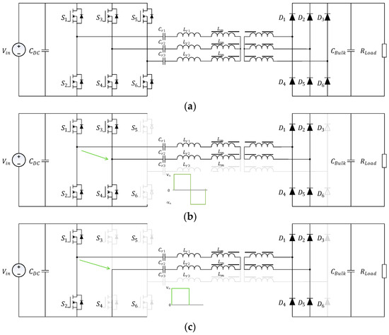
The three operating configurations considered in this work are summarized in Figure 1. Comprehensive analyses of the three-phase LLC resonant converter are available in [6] and [9], while the operating principles and design of conventional full-bridge and half-bridge LLC converters are discussed in [3,4] and [1,2], respectively. The present work therefore focuses on the proposed rotating phase-shedding control strategy and its application to the single-phase half-bridge operating mode of a three-phase LLC resonant converter.
Figure 1.
Three-phase LLC resonant converter operational modes (a) three phase, (b) two phase, (c) half bridge.
2.1. Three-Phase Operation Mode
The conventional three-phase mode is illustrated in Figure 1a. In this configuration, all three converter phases participate in power transfer. The gate-drive signals of phases , , and are mutually displaced by , resulting in symmetrical excitation of the three resonant tanks.
Assuming identical resonant-tank parameters and balanced operation, the three phase currents have equal RMS values. The total output power is therefore equally distributed among the phases, and the power transferred by each phase is given by
This mode provides the full rated-power capability of the converter and is used over the nominal output-voltage range. Its minimum output voltage is determined by the minimum achievable resonant-tank gain and the maximum permissible switching frequency.
2.2. Two-Phase Operation Mode
The two-phase full-bridge mode is shown in Figure 1b. One converter phase is disabled, while the two remaining converter legs form a full-bridge configuration. The switches of the active legs are driven using complementary PWM signals with the required dead time, and a relative phase displacement of is applied between the legs to generate a bipolar excitation voltage.
The reduction in the number of active phases limits the maximum available output power:
This limitation arises from the RMS current per phase.
2.3. Single-Phase Half-Bridge Operating Mode
The single-phase half-bridge operating mode is employed in the lowest-output-voltage region. In this configuration, two resonant phases are disabled, and only one phase actively transfers power to the secondary side. One switch of another converter leg is maintained in a constant conducting state to establish the required voltage reference and current return path Figure 1c. The resulting configuration allows the active resonant phase to operate as a conventional half-bridge LLC converter.
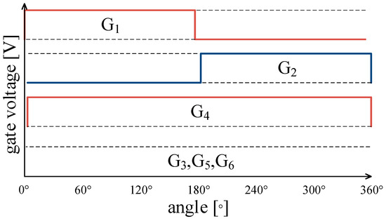
The two switches of the active phase leg are driven by complementary gate signals with an appropriate dead time. In the supporting leg, the designated switch remains continuously turned on, while its complementary switch remains turned off. Both switching devices of the third leg remain disabled. Figure 2 illustrates gate signals, in which S1 and S2 operate as the active switches of phase , S4 provides the current return path through phase , and S3, S5, and S6 remain disabled.
Figure 2.
Half-bridge operational mode gate signals: phase is active, phase is support, and phase is inactive.
Since the voltage applied to the resonant tank is halved compared with two-phase full-bridge configurations, this mode further extends the converter operating range toward lower output voltages.
The output-power capability is limited because only one resonant phase contributes to power transfer. Assuming identical power capability for all three phases, the maximum output power in the single-phase half-bridge mode is approximately one-third of the rated converter power:
In conventional fixed-phase operation, continuous selection of the same active phase results in nonuniform utilization and localized thermal loading. The rotating phase-shedding strategy proposed in this work addresses this limitation by periodically transferring the active half-bridge state among phases , , and . This approach preserves the electrical characteristics of the single-phase operating mode while distributing the accumulated power losses and thermal stress among all three converter phases.
2.4. Comparison of the Operating Modes
The three-phase mode covers the nominal output-voltage range and provides the full rated power of the converter. The two-phase full-bridge mode extends operation toward lower output voltages, whereas the single-phase half-bridge mode provides a further reduction in the achievable output voltage. All three configurations operate within the same specified switching-frequency range.
The combined output-voltage range is given by the union of the voltage ranges available in the individual modes:
where , , and denote the output-voltage ranges of the three-phase, two-phase full-bridge, and single-phase half-bridge modes, respectively. An overlap between adjacent operating ranges is desirable to facilitate smooth mode transitions and enable the implementation of hysteresis.
An operating mode can be selected only when the required output voltage and power satisfy
and
where identifies the selected operating mode. The operating point must additionally remain within the permissible semiconductor current, transformer current, and thermal stress. In regions where two operating modes are feasible, the preferred mode can be selected based on efficiency, current stress, thermal loading, and transition behavior.
The principal characteristics of the individual operating modes are summarized in Table 1.
Table 1.
Comparison of the converter operating modes.
In the conventional implementation of the single-phase half-bridge mode, one phase remains continuously active, resulting in unequal accumulated losses and thermal loading. This limitation provides the motivation for the rotating phase-shedding method introduced in the following section.
2.5. Rotating Phase-Shedding in Half-Bridge Mode
The proposed method rotates the active half-bridge state among all three phases. A general rotation sequence can be defined as
followed by a return to . Here, the subscript “active” identifies the switching phase, “support” denotes the leg with the required fixed switched state, and “off” represents the inactive leg. The rotating intervals are equal:
Similarly, each phase assumes the supporting and inactive roles for one-third of the total operating time. The accumulated losses of the active MOSFETs together with the rectifier diodes are theoretically analyzed in the following subsection.
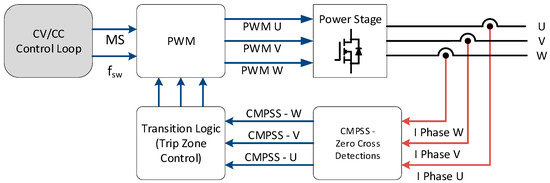
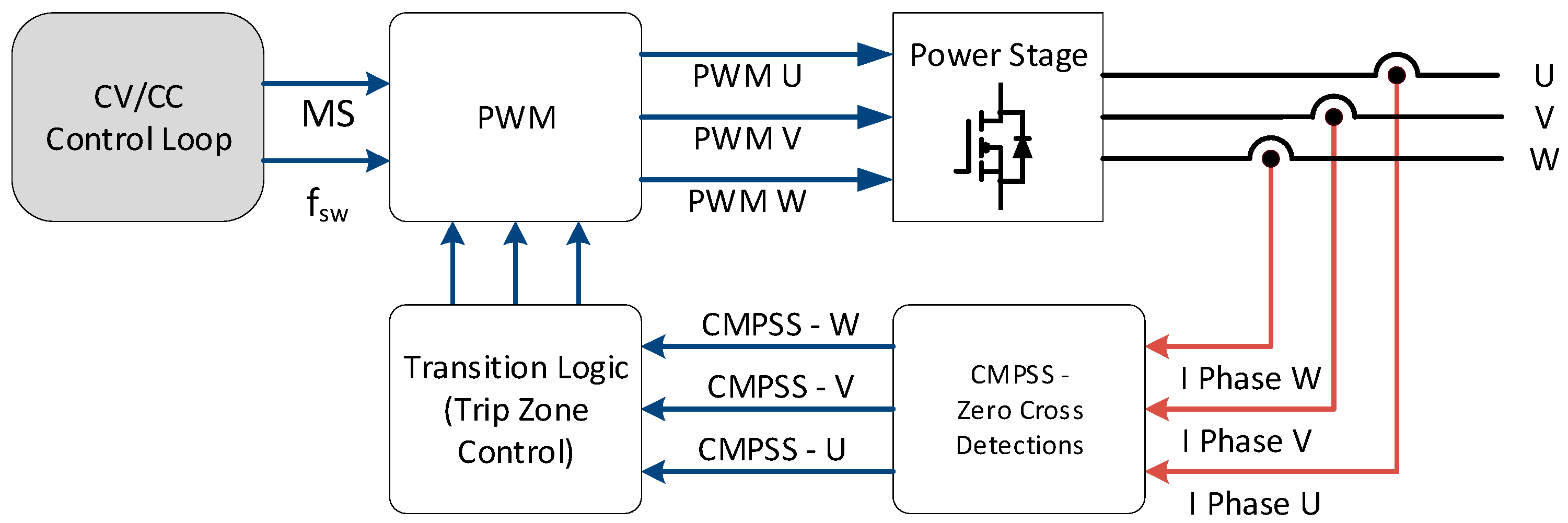
The transition between consecutive states must be synchronized with the PWM time base. The transition logic is described in Figure 3. The base idea is to use an internal ADC comparator and Trip Zone Control in PWMs peripherals. A detailed description of the transition process is provided in Section 3.
Figure 3.
Control block diagram; MS—mode selection, CMPSS—MCU internal comparators of ADCs; phase current measurements is provided with 1 MHz sensor bandwidth.
2.6. Semiconductor Loss Model for Fixed and Rotating Phase-Shedding
A semiconductor loss analysis is performed to distinguish the redistribution of losses from a reduction in the total converter losses. From a component-level perspective, the analyzed semiconductor losses comprise the losses in the primary-side MOSFETs and the secondary-side rectifier diodes. Losses associated with the transformer, control electronics, gate-driver circuitry, and auxiliary power supplies are neglected in this analysis. The MOSFET power losses are described by the following equations:
where represents the conduction losses of the active MOSFET, denotes the switching losses, and represents the gate-drive losses. These loss components are described below:
where is the RMS current through the MOSFET, and is the on-state resistance evaluated at the estimated junction temperature .
where is the switching frequency, and and are the turn-on and turn-off switching energies, respectively. Operation of the converter under ZVS conditions significantly reduces .
where is the gate charge, and is the total bipolar gate-voltage excursion.
In the supporting leg, only conduction losses are considered and are calculated using the same expression as in (12).
For the rectifier stage, the reverse-recovery losses of the SiC Schottky diodes are negligible. Therefore, the rectifier-diode losses are approximated by the conduction losses , which are calculated using the following equation:
where is diode forward voltage, is average rectifier current, and is dynamic resistance.
Assume the fixed state of operation described in Equation (7). The power losses of fixed phase-shedding are described below:
The total power loss for fixed phase-shedding is
For rotating phase-shedding operation, the loss distribution differs from that under fixed operation. As defined in (10), each phase sequentially assumes the active, supporting, and inactive roles for one-third of the rotation period. Consequently, the time-averaged loss of each phase can be expressed as follows:
The total power loss under rotating phase-shedding operation can then be expressed as follows:
The provided loss analysis indicates comparable total power losses under fixed and rotating phase-shedding operation; therefore, no significant improvement in overall converter efficiency is expected. The primary benefit of the rotating strategy is the more uniform distribution of accumulated losses and thermal stress among the converter phases.
3. Experimental Validation
3.1. Experimental Prototype and Measurement Setup
An experimental prototype was developed to validate the proposed rotating phase-shedding strategy under practical operating conditions. The prototype is based on a three-phase LLC resonant converter and supports conventional three-phase operation, two-phase full-bridge operation, and single-phase half-bridge operation. The electrical parameters and principal specifications of the converter are summarized in Table 2.
Table 2.
Converter parameter overview.
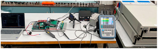
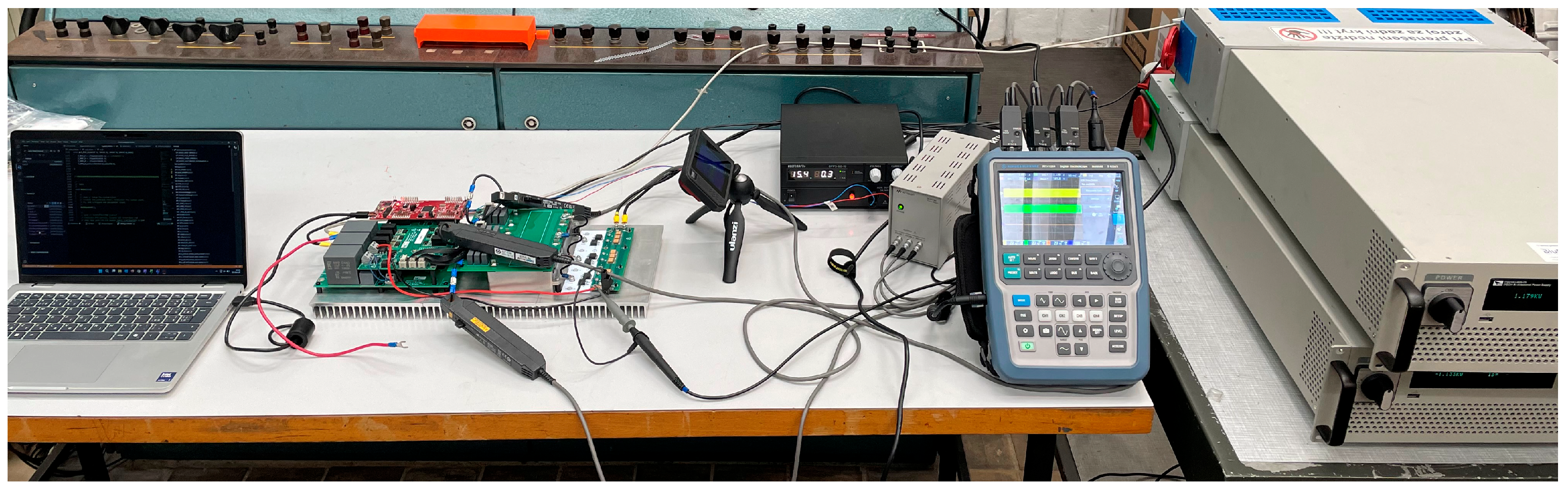
The experimental setup is shown in Figure 4: a control PC, the converter under test, a thermal camera, a digital oscilloscope, and an auxiliary power supply. Two bidirectional power supplies operate as the input DC source and electronic load, respectively.
Figure 4.
Test bench setup.
To ensure a valid comparison between fixed and rotating phase-shedding, all measurements are performed at the same input voltage VIN = 350 V. The temperature distribution is evaluated after the converter reaches thermal steady state.
3.2. Steady-State Operation
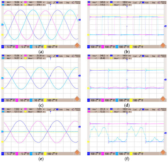
Figure 5 presents oscillograms corresponding to the three operating modes. The oscillograms in the left column show the transformer currents of phases , , and on Channels 1, 2, and 3 (Ch1–Ch3), respectively. Channel 4 (Ch4) represents the converter output voltage. The oscillograms in the right column show the switching-node voltages of the three converter legs, measured with respect to the negative DC-link terminal (), on Ch1–Ch3. The output voltage is again displayed on Ch4. The output-voltage waveform serves as a common reference for measurements.
Figure 5.
Three-phase LLC resonant converter operational modes—three-phase mode: (a) phase currents, (b) phase voltages; two-phase mode: (c) phase Currents, (d) phase voltages; half-bridge mode: (e) phase currents (f) phase Voltages; VIN = 350 V and Rload = 30 Ohm and fsw = 100 kHz.
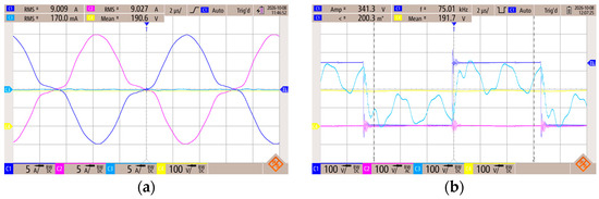
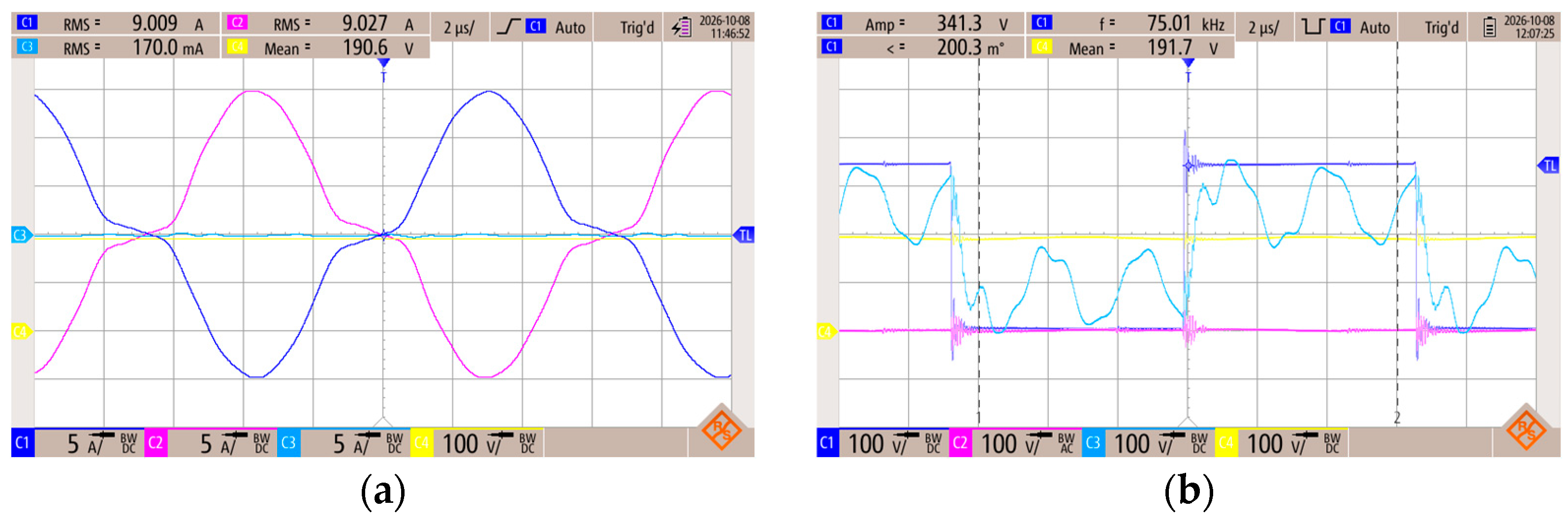
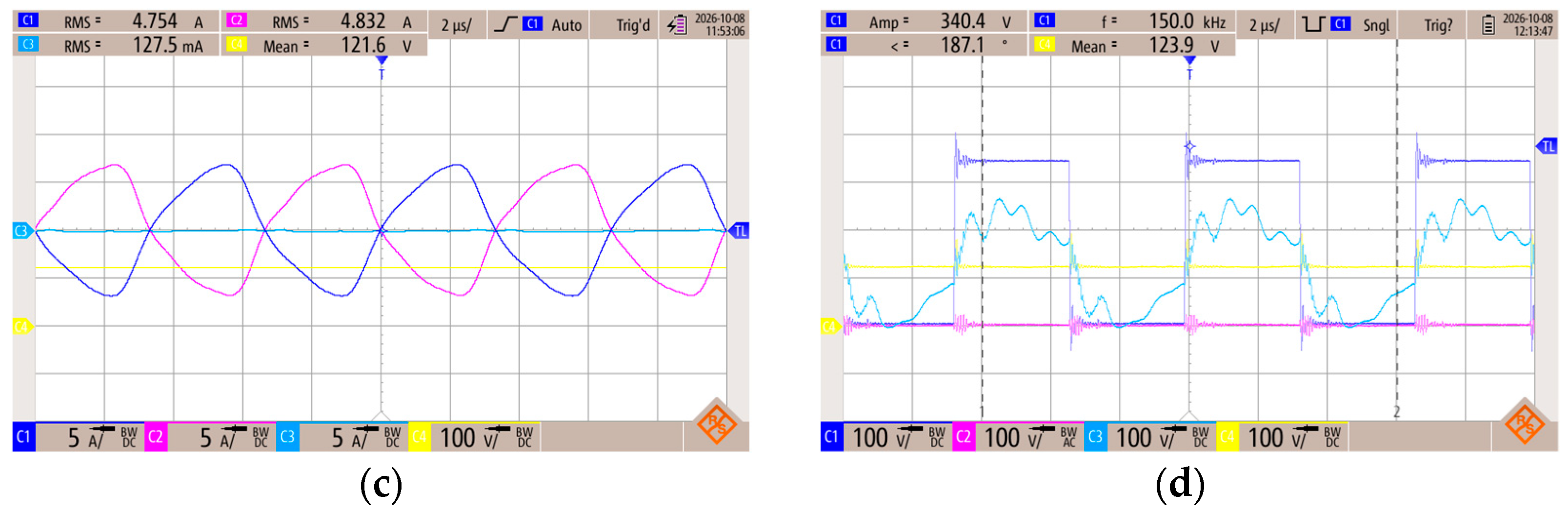
Particular attention should be given to the single-phase half-bridge operating mode shown in Figure 5f. In this configuration, the voltage measured on Ch3 represents the floating switching-node voltage of the inactive converter leg. Meanwhile, the voltage on Ch2 remains at the positive DC-link potential because the high-side switch of the corresponding phase is continuously turned on to provide the return path for the resonant current. Figure 6 presents the measured switching waveforms of the half-bridge operation at different switching frequencies.
Figure 6.
Half-bridge mode operations: (a) phase currents fsw = 75 kHz, (b) phase voltages fsw = 75 kHz, (c) phase currents fsw = 150 kHz, (d) phase Voltages fsw = 150 kHz; operational VIN = 350 V and Rload = 30 Ohm.
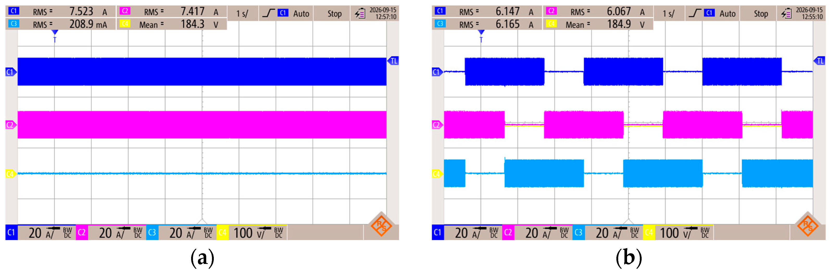
Figure 7 compares the transformer current waveforms in the single-phase half-bridge operating mode. The oscillogram (a) shows conventional fixed-phase operation, whereas the oscillogram on (b) presents the proposed rotating phase-shedding operation with = 3.3 s, = 1.1 s. Both measurements were performed at the same operating point VIN = 350 V and Rload = 30 Ohm and fsw = 100 kHz.
Figure 7.
Half-bridge mode: (a) fixed phase-shedding; (b) rotating phase-shedding.
During fixed-phase operation, phase carries no current because it remains inactive throughout the measurement interval. In contrast, during the proposed rotating phase-shedding operation, all three phases participate sequentially in power transfer.
The resonant current is periodically transferred among the operating states , , and , as defined previously. Consequently, each phase assumes the active role for a specified interval, resulting in a more uniform distribution of accumulated electrical and thermal loading among the converter phases.
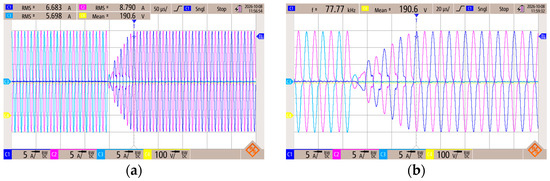
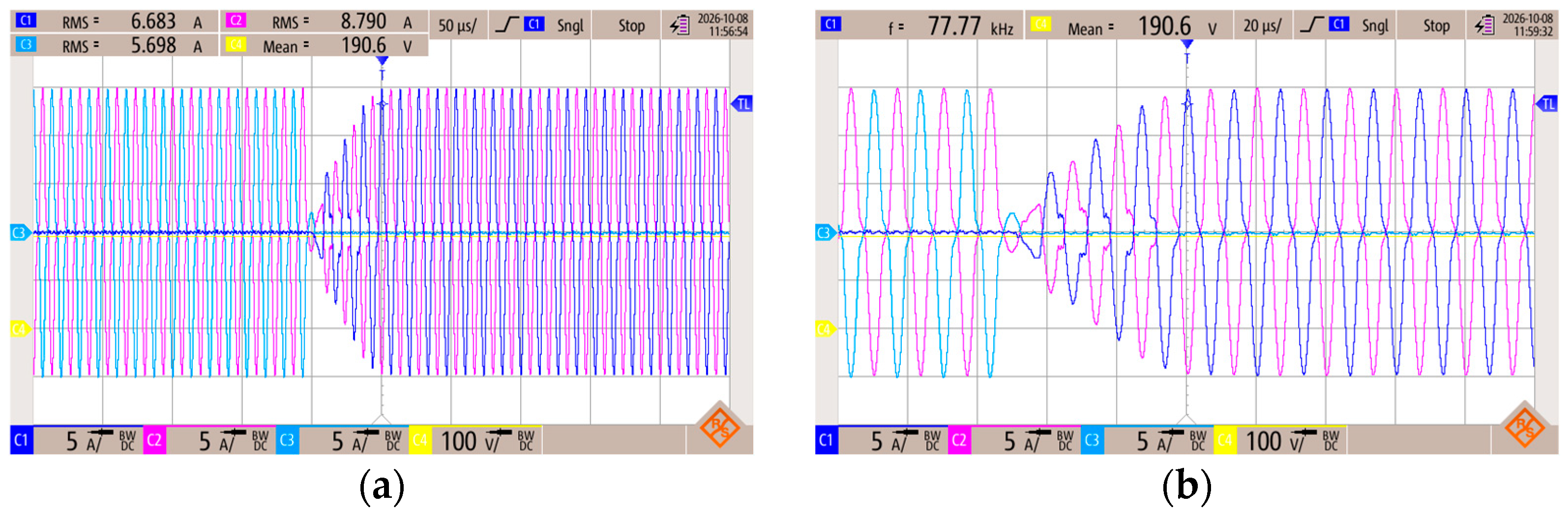
Figure 8 presents the transition between and states at a switching frequency of fsw = 75 kHz, the same operational point as earlier. The transition is shown using both an extended time scale and a detailed view. The measured waveforms demonstrate a smooth transfer between the phases, with transient behavior limited to only several switching cycles. Before the transition, phase is inactive, as shown on Ch1. After the transition, phase becomes inactive, as shown on Ch3.
Figure 8.
Transition from to ; currents of phase , , correspond to Ch1, Ch2, Ch3; Output voltage is on Ch4: (a) extended time scale; (b) detailed view.
Since the laboratory load has a large input capacitance, no significant output-voltage transient is observed during the state transition. The input capacitance of the load provides additional filtering and suppresses short-term voltage disturbances. In practical applications, the output capacitance should be sufficiently large to maintain the output voltage during transitions between rotational states.
3.3. Output Voltage Range
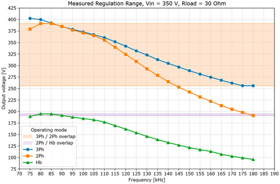
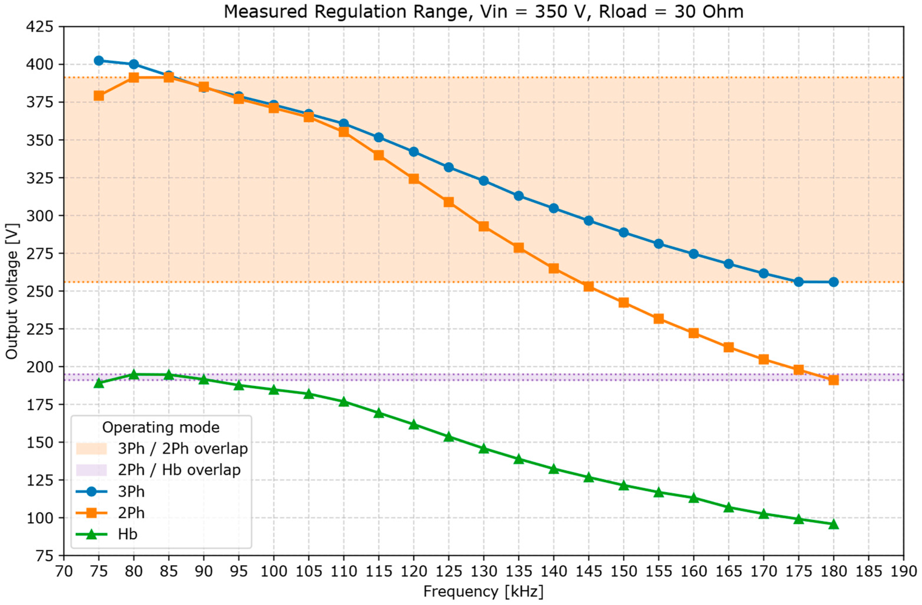
The extended output voltage range is presented in Figure 9 as a function of the switching frequency and the selected operating mode. The output voltage ranges of the three-phase (3Ph) and two-phase (2Ph) full-bridge modes demonstrate a significant overlap. This overlapping region allows the control system to select the more efficient operating mode at operating points that can be achieved using either configuration. In comparison, the overlap between the two-phase full-bridge and single-phase half-bridge (HB) modes is narrower, thereby providing less flexibility for efficiency-based mode selection.
Figure 9.
VOUT based on fsw and operational mode and overlapping regions.
The measurement results demonstrate that the proposed multimode operating strategy provides a significant extension of the converter output-voltage range. By transitioning among the three-phase, two-phase full-bridge, and single-phase half-bridge modes, the output voltage can be regulated from approximately 400 V down to 100 V while maintaining the specified switching-frequency range.
3.4. Thermal Performance
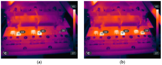
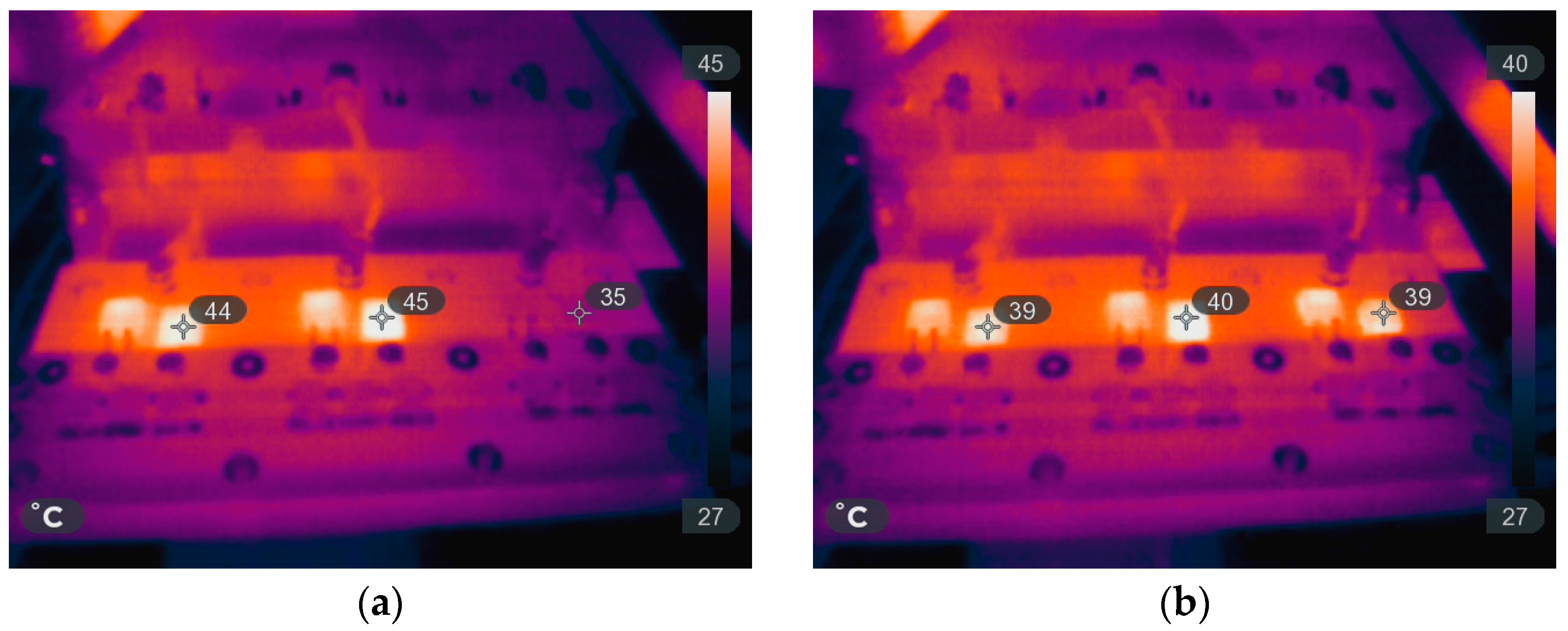
The temperature measurements of the secondary side rectifier diodes are presented in Figure 10. The operational points correspond to fixed mode Figure 7a,b rotating half-bridge mode. Under the fixed operation, the unequal utilization of the converter phases results in a nonuniform temperature distribution across the rectifier diodes. In comparison, the proposed rotating phase-shedding mode sequentially distributes the power-transfer intervals among all three phases. As a result, the corresponding losses are distributed more uniformly, reducing the maximum diode temperature and improving the thermal balance of the converter.
Figure 10.
Thermal camera measurement results: (a) fixed phase-shedding mode, (b) rotating phase-shedding mode.
4. Discussion
The three-phase LLC resonant converter investigated in this work demonstrates a wide output-voltage regulation range. Through the application of the proposed phase-shedding strategy, the converter output voltage can be regulated from approximately 400 V down to 100 V, with the lowest output-voltage region achieved in the single-phase half-bridge operating mode.
However, the extension of the output-voltage range is accompanied by a reduction in the available output power. This power derating results from the reduced number of active resonant phases. While all three phases contribute to power transfer in the conventional three-phase mode, only two phases participate in the two-phase full-bridge mode, and only one phase actively transfers power in the single-phase half-bridge mode. Therefore, the maximum output-power capability decreases as the converter transitions toward lower-voltage operating modes.
In conventional fixed half-bridge operation, the same phase remains active throughout the entire operating interval, while a second phase provides the supporting current path. The third phase remains inactive. This unequal phase utilization results in an asymmetric distribution of phase currents and power losses. Consequently, the continuously active phase and its corresponding semiconductor and magnetic components experience higher cumulative electrical and thermal stress, leading to a nonuniform temperature distribution within the converter.
The proposed rotating phase-shedding strategy addresses this limitation by periodically transferring the active and supporting states among all three converter phases. Although only one phase actively transfers power during each individual operating state, phases , , and participate sequentially over the complete rotation cycle. This approach distributes the accumulated current stress and power losses more uniformly among the converter phases.
The experimental results demonstrate that rotating phase-shedding improves the thermal distribution within the converter and reduces localized thermal loading compared with fixed half-bridge operation are summarized in Table 3.
Table 3.
Measurement results.
It should be noted that the proposed method does not necessarily reduce the instantaneous total converter losses. Instead, the principal benefit of the proposed strategy is the more uniform distribution of accumulated losses among the converter phases. Experimentally, the maximum temperature difference between the phases was reduced from approximately 10 °C in the fixed operating mode to 1 °C with rotating phase-shedding. This improves converter hardware utilization and may reduce the thermal stress imposed on individual components during prolonged operation in the single-phase half-bridge mode.
5. Conclusions
This work demonstrates that rotating phase-shedding provides an effective means of improving phase utilization during single-phase half-bridge operation of a three-phase LLC resonant converter. By periodically exchanging the active, supporting, and inactive phase assignments, the proposed strategy avoids the persistent loading of one converter phase associated with conventional fixed phase-shedding.
The operating principles of the converter were analyzed in Figure 5 for the three-phase, two-phase full-bridge, and single-phase half-bridge modes, including the proposed rotating phase-shedding strategy (Figure 7). The achievable output-voltage range was experimentally evaluated for each operating mode (Figure 9). In addition, the transition behavior among the rotating phase-shedding states was investigated and documented in Figure 8.
Experimental thermal measurements confirm uniform temperature distribution across the secondary-side rectifier diodes (Figure 10); the maximum temperature difference between phases is 1 °C. Since each power transfer path includes the corresponding primary-side switching devices, transformer, and rectifier branch, a similar improvement is expected throughout the converter. Nevertheless, direct measurements of the primary-side semiconductor are not possible in this setup.
Future research should focus on efficiency measurements and direct monitoring of the primary-side MOSFET temperatures to provide a quantitative comparison between conventional fixed phase-shedding and rotating phase-shedding operation.
Author Contributions
Conceptualization, F.F. and P.S.; Methodology, F.F. and P.S.; Software, F.F.; Validation, F.F. and P.S.; Formal analysis, F.F. and P.S.; Investigation, F.F.; Resources, F.F.; Writing – original draft, F.F.; Writing – review & editing, P.S.; Visualization, F.F. and P.S.; Supervision, P.S. and J.L.; Project administration, J.L.; Funding acquisition, F.F.. All authors have read and agreed to the published version of the manuscript.
Funding
This research was funded by Czech Technical University in Prague (Grant No. SGS25/140/OHK3/3T/13).
Data Availability Statement
The original contributions presented in this study are included in the article. Further inquiries can be directed to the corresponding author.
Conflicts of Interest
The authors declare no conflict of interest.
References
- Steigerwald, R.L. A Comparison of Half-Bridge Resonant Converter Topologies. IEEE Trans. Power Electron. 1988, 3, 174–182. [Google Scholar] [CrossRef] [Scilit]
- Yang, B.; Lee, F.C.; Zhang, A.J.; Huang, G. Llc Resonant Converter for Front End Dc/Dc Conversion. In Proceedings of the APEC Seventeenth Annual IEEE Applied Power Electronics Conference and Exposition (Cat. No.02CH37335); IEEE: Piscataway, NJ, USA, 2002. [Google Scholar] [CrossRef] [Scilit]
- Ramos-Paja, C.A.; Ramirez Scarpetta, J.M.; Martinez-Salamero, L. Integrated Learning Platform for Internet-Based Control-Engineering Education. IEEE Trans. Ind. Electron. 2010, 57, 3284–3296. [Google Scholar] [CrossRef] [Scilit]
- Adragna, C.; De Simone, S.; Spini, C. A Design Methodology for Llc Resonant Converters Based on Inspection of Resonant Tank Currents. In Proceedings of the 2008 Twenty-Third Annual IEEE Applied Power Electronics Conference and Exposition; IEEE: Piscataway, NJ, USA, 2008. [Google Scholar] [CrossRef] [Scilit]
- Millán, J.; Godignon, P.; Perpiñà, X.; Pérez-Tomás, A.; Rebollo, J. A Survey of Wide Bandgap Power Semiconductor Devices. IEEE Trans. Power Electron. 2014, 29, 2155–2163. [Google Scholar] [CrossRef] [Scilit]
- Orietti, E.; Mattavelli, P.; Spiazzi, G.; Adragna, C.; Gattavari, G. Current Sharing in Three-Phase Llc Interleaved Resonant Converter. In Proceedings of the 2009 IEEE Energy Conversion Congress and Exposition; IEEE: Piscataway, NJ, USA, 2009. [Google Scholar] [CrossRef] [Scilit]
- Fei, C.; Gadelrab, R.; Li, Q.; Lee, F.C.; Gattavari, G. High-Frequency Three-Phase Interleaved Llc Resonant Converter with Gan Devices and Integrated Planar Magnetics. IEEE J. Emerg. Sel. Top. Power Electron. 2019, 7, 653–663. [Google Scholar] [CrossRef] [Scilit]
- Gadelrab, R.; Lee, F.C.; Li, Q.; Gattavari, G. Three-Phase Interleaved Llc Resonant Converter with Integrated Planar Magnetics for Telecom and Server Application. In Proceedings of the 2020 IEEE Applied Power Electronics Conference and Exposition (APEC); IEEE: Piscataway, NJ, USA, 2020. [Google Scholar] [CrossRef] [Scilit]
- Lin, J.-Y.; Yueh, H.-Y.; Lin, Y.-F.; Liu, P.-H.; Gattavari, G. Analysis and Design of Three-Phase Llc Resonant Converter with Matrix Transformers. Energies 2022, 15, 1315. [Google Scholar] [CrossRef] [Scilit]
- Feng, X.; Wang, S.; Li, Z.; Dai, Z.; Gattavari, G. Design of Three-Phase Staggered Llc Resonant Converter with Flexible Transition Control for Wide Voltage Gain. J. Electr. Eng. 2022, 18, 441–455. [Google Scholar] [CrossRef] [Scilit]
- Jiang, H.; Yue, X.; Li, Z.; Dai, Z.; Gattavari, G. Phase-Shifting Adaptive Llc Resonant Converter with Reduced Turn-Off Loss in Wide Voltage Application. Energies 2024, 17, 1555. [Google Scholar] [CrossRef] [Scilit]
- Abdel-Rahim, O.; Alamir, N.; Abdelrahem, M.; Orabi, M.; Kennel, R.; Ismeil, M.A. A Phase-Shift-Modulated Llc-Resonant Micro-Inverter Based on Fixed Frequency Predictive-Mppt. Energies 2020, 13, 1460. [Google Scholar] [CrossRef] [Scilit]
- Arshadi, S.A.; Ordonez, M.; Mohammadi, M.; Eberle, W.; Kennel, R.; Ismeil, M.A. Efficiency Improvement of Three-Phase Llc Resonant Converter Using Phase Shedding. In Proceedings of the 2017 IEEE Energy Conversion Congress and Exposition (ECCE); IEEE: Piscataway, NJ, USA, 2017. [Google Scholar] [CrossRef] [Scilit]
- Ahmad, U.; Giral, R.; Olalla, C.; Sangwongwanich, A.; Davari, P.; Blaabjerg, F. Multiphase Llc Resonant Converter with Natural Current Sharing and Phase-Shedding. IEEE Trans. Ind. Appl. 2025, 61, 6524–6534. [Google Scholar] [CrossRef] [Scilit]
- Chiba, A.; Aoyagi, Y.; Takagi, K.; Sangwongwanich, A.; Davari, P.; Blaabjerg, F. Current Balancing and Phase Shedding by Split Capacitor for a Three-Phase Llc Resonant Converter. In Proceedings of the 2020 IEEE Energy Convers Congress and Exposition (ECCE); IEEE: Piscataway, NJ, USA, 2020. [Google Scholar] [CrossRef] [Scilit]
- Cousineau, M.; Monroy, M.; Lorenzi Pol, W.; Hureau, L.; Aulagnier, G.; Goyhenetche, P.; Rolland, E.; Flumian, D. Decentralized Phase Shedding with Low Power Mode for Multiphase Converter. Energies 2021, 14, 6748. [Google Scholar] [CrossRef] [Scilit]
- Xiao, Z.; Yao, Z.; Deng, F.; Zhang, L.; Tang, Y.; Goyhenetche, P.; Rolland, E.; Flumian, D. Seamless Rotational Phase Shedding for Multiphase Dc–Dc Converters. IEEE Trans. Power Electron. 2024, 39, 4996–5001. [Google Scholar] [CrossRef] [Scilit]

Disclaimer/Publisher’s Note: The statements, opinions and data contained in all publications are solely those of the individual author(s) and contributor(s) and not of MDPI and/or the editor(s). MDPI and/or the editor(s) disclaim responsibility for any injury to people or property resulting from any ideas, methods, instructions or products referred to in the content. |
© 2026 by the authors. Licensee MDPI, Basel, Switzerland. This article is an open access article distributed under the terms and conditions of the Creative Commons Attribution (CC BY) license.