


Abstract
This paper presents an experimental investigation of a wet steam cycle (WSC) for waste-heat-to-power conversion using a rotary blower as an expander. In a WSC, the entire process takes place in the wet-steam region. To determine suitable rotary blower and generator parameters for testing, preliminary simulations were carried out using Ebsilon Professional software. Wet steam was produced by injecting feedwater into the saturated steam pipeline. To ensure a homogeneous mixture, the necessary length of straight pipe downstream of the injection nozzle was determined using CFD analysis. A detailed design was then developed, and a test stand was constructed. During the experimental test, the wet-steam gauge pressure at the expander inlet ranged from 2 bar to 2.8 bar. Wet steam mass flow rates were 425–500 kg/h with a steam quality of approximately 0.7–0.83. Generator output power ranged from 70 W to 130 W. The calculated isentropic efficiency of the expander ranged from approximately 7% to approximately 10%. The findings show that this expander type can be used to generate electricity from waste heat by implementing WSC. To the authors’ knowledge, no comparable studies have been reported to date. The cycle can contribute to more sustainable energy use when the available waste heat is insufficient to generate superheated or saturated steam.
1. Introduction
In recent decades, energy demand has increased significantly. This increase is primarily due to rising living standards, population growth, and the growing number of electrically powered devices. It has become necessary to seek and implement new energy generation systems. As a result, extensive research and development have been carried out in areas such as innovative energy systems and waste heat recovery [1]. The aim was to protect the environment by using energy efficiently. Waste heat offers significant potential in this regard. The recovery of waste heat on a small/distributed scale typically involves converting it into electricity at low- to medium-temperature levels. The process infrastructure should be kept as simple as possible, and environmentally friendly working fluids should be used. Unfortunately, many fluids used in the Organic Rankine Cycle (ORC) are subject to safety-related restrictions. According to Bao and Zhao [2], numerous reviews of low-temperature systems suggest that selecting the ORC fluid should balance efficiency and operating safety.
Water is non-flammable and non-toxic. However, in many attempts to use low-temperature energy sources, a significant problem arises: insufficient heat is available to produce superheated steam [3]. In micro-CHP (Combined Heat and Power) systems supplied with biomass or waste heat, steam superheaters are a limiting factor. At a low fluid pressure (approximately 1 MPa), steam reaches only the saturation state. In practice, during throttling and expansion in simple steam systems, even slight superheating quickly disappears, and operation proceeds on saturated steam [4]. Studies of ejector nozzles have also shown that non-equilibrium condensation occurs in steam, even at low levels of superheating [5]. The available results for steam condensation in supersonic nozzles confirm that the transition to a liquid–vapour mixture is typical under such conditions [6]. As a result, many systems rely on saturated or wet steam, provided the expander structure permits it. Theoretical analyses and a few experimental studies indicate that, despite reduced efficiency, the use of wet steam is feasible and can be profitable, provided that the expansion machine can tolerate liquid in the flow [7].
Due to frequent instability in superheated steam, numerous computational approaches for saturated or wet steam are currently being developed. This primarily concerns CFD and various reduced models. CFD modelling of processes related to wet steam and condensation (nucleation, droplet growth) is well recognised and utilised in the analysis of specific devices, such as ejectors [4], nozzles [5], blade cascades, and turbine stages [6]. For ejectors, for example, it has been shown that using the ideal-gas model leads to an erroneous assessment of losses [4]. These issues are also analysed in two-dimensional terms for turbines [7], in sealing zones of volumetric expanders [8], and during expansion in volumetric machines [9]. Classical papers on nozzles and turbines confirm the need to account for condensation in the calculation of their stages [6] and extend this to two-dimensional cascade calculations [7].
The key issues in volumetric machines are the impact of two-phase flow on the sealing zones. At long residence times and low steam quality, full condensation within the chamber volume is possible. For example, in [8], attention was drawn to leak-related problems, and the importance of research on sealing the screw expander shaft was highlighted. The literature emphasises that classic steam turbines do not tolerate liquid ingress, as it can lead to blade erosion, increased losses, and reduced service life. For this reason, volumetric expanders (screw, scroll, vane, piston, and Roots) are considered more resilient solutions for small-scale and low-temperature applications [10]. For example, He et al. [11] presented the benefits of using a screw expander in Steam Pressure Energy Recovery (SPER) systems.
An interesting method of waste heat management, widely described in the literature, is the Trilateral Flash Cycle (TFC). Unlike in the ORC, the working fluid in the TFC expands from the saturated liquid phase to a two-phase mixture. The TFC’s main advantage is a significant reduction in exergy losses in the heat exchanger, as evaporation does not occur within it [12]. The results of experiments with a nozzle and an impulse turbine demonstrate that the TFC can generate more power than the ORC using the same heat source and can operate effectively even with heat sources below 80 °C [13]. In a case study on integrating TFC with an existing ORC system, Iqbal et al. [13] report a significant increase in energy production and economic profitability. A payback period of less than 10 years was obtained at the nozzle isentropic efficiency of 40%. In TFC systems, the expander operates on a liquid-steam mixture from the very beginning, which requires two-phase flow tolerance [14]. In ORC variants with liquid-flooded expansion, the requirements are the same [15]. In steam-cascade systems, expansion is performed in a screw expander [16]. Theoretical and model analyses confirm that screw expanders tolerate the wet phase and maintain stable performance under part-load conditions [14,15,16]. Demonstration results for such an expander with direct steam generation show stable operation in two-phase conditions [17]. The thermo-economic evaluation of systems with tandem screw expanders indicates that this configuration is justified in terms of both energy and costs [18]. In SPER applications, screw expanders replace throttling valves, increasing exergy efficiency by up to 17% [11]. Simulations and dynamic tests indicate that condensation within the twin-screw steam expander chamber intensifies at low loads [19]. As Nikolov and Brümmer point out [20], effective sealing and lubrication reduce leakage and stabilise the operation of such an expander under multi-phase flow conditions.
An alternative to screw machines is the Roots expander. It is a rotary blower operating in reverse cycle. Comparative studies of four types of expanders (scroll, screw, piston, and Roots) showed that Roots units achieved lower isentropic efficiencies but were characterised by a simple structure, low cost, and potential resistance to liquid [21]. The ORC demonstrators also confirmed the feasibility of integrating a Roots expander into an energy system, thereby justifying the use of such a device for recovering energy from small sources [22]. The main limitations of this machine are leaks through gaps and a lack of internal compression, which reduce efficiency at large pressure differences. The mechanisms of these losses are clearly visible in CFD simulations [23]. Oil injection can enhance sealing and prevent inter-fin leakage, thereby improving efficiency and stabilising multi-phase flow operation [24]. Numerical analyses also indicate that the geometry and location of the inlet/outlet channels, as well as the distribution of gaps in the volume chambers, influence the shape of pressure pulsations. In addition, the areas most susceptible to the oil’s sealing effect are identified [24].
Previous experimental studies have been conducted mainly in organic media in ORC systems, limiting the direct extrapolation of the conclusions to steam [22]. For saturated and wet steam, the literature tends to emphasise the need for dedicated test stands and research rather than relying on ready-made sets of operating data, which clearly defines the research gap [25]. The test stand and the results presented in the present paper for the saturated/wet-steam reverse Roots blower substantially fill this gap and provide new empirical data.
As previously mentioned, under industrial and demonstration conditions, the available waste-heat flux is often insufficient to maintain stable steam superheating. For this reason, as Xu et al. [26] point out, many systems operate using saturated steam. This phenomenon is particularly evident in systems connected to existing sources (e.g., downstream of an extraction-backpressure turbine), where the available temperature and thermal power limit the extent of real superheating [27]. As indicated by the reviews of small-scale solutions, steam systems operating without permanent superheating are dominant in practice [28]. The commercially available Heliex systems with screw expanders, which are dedicated to operate with saturated or wet steam and do not include a superheater, are an example [29]. Other volumetric expanders are also used in small-scale applications simultaneously (e.g., multi-vane devices), as confirmed by ORC research and implementation [30]. Reviews of such structures indicate that they are resistant to typical no-superheating operating conditions [31]. In practice, system efficiency is strongly dependent on steam quality; as it decreases, the expander’s partial-load characteristics degrade rapidly [19]. Additionally, leaks and seal condition determine losses in two-phase flow, as confirmed by analyses of sealing zones in screw machines [8].
Partial evaporation ORC (PE-ORC) shows some similarity to the two-phase flow [32,33]. PE-ORC is a transition cycle between ORC and TFC. The use of a PE-ORC is necessary to effectively recover heat at temperatures below 100 °C [33]. In this case, the working fluid undergoes only partial evaporation and expansion under two-phase conditions. This results in a better match between the heat source and the working fluid’s temperature profile, leading to higher cycle exergy efficiency. However, references [32,33] are purely theoretical. Recent studies have also provided quantitative comparisons between ORC variants with two-phase expansion under similar heat-source conditions. Bellos [34] compared conventional ORC, PE-ORC, and TFC for waste-heat temperatures from 100 to 250 °C and reported system efficiencies of 6.49% for PE-ORC, 6.31% for ORC, and 5.50% for TFC at a heat-source temperature of 150 °C. Dawo et al. [35] experimentally compared PE-ORC and conventional ORC for heat-source temperatures of 110–140 °C and showed that PE-ORC can achieve substantially higher exergy efficiency due to improved heat-source utilisation. These results confirm the potential of two-phase expansion cycles for low-temperature waste-heat recovery, although a direct comparison with the present WSC is not straightforward because of differences in the working fluid, expander type, and boundary conditions.
The literature review shows that most publications focus on expanders in ORC systems. This is because efficient, affordable expanders are crucial to the cost-effectiveness of these systems. Despite the broad recognition of scroll, screw, piston, vane, and roots technologies for waste heat recovery [10,21], very little information is available on the use of wet steam to drive these expanders. Comprehensive comparisons of volumetric expander technologies are already available in the literature. Imran et al. [10] reviewed vane, screw, scroll and piston expanders for ORC waste-heat-recovery applications, while Dumont et al. [21] experimentally compared scroll, screw, piston and Roots expanders using R245fa as the working fluid. However, these comparisons concern organic working fluids and do not provide a corresponding experimental data set for a Roots expander supplied directly with wet steam. Only limited information is available on the use of a saturated steam-driven rotary blower in a glass factory [36] or of a commercially available wet-steam driven twin-screw expander [29]. A preliminary description of the issue and a concept for a test stand to study the wet-steam cycle (WSC) are also available in [25]. A distinguishing feature of the proposed WSC is that it both starts and ends within the wet-steam region. Therefore, the expanders used must tolerate a certain amount of condensate in the steam. The WSC proposed in this paper combines the thermodynamic advantages of the TFC process with the advantages of the conventional saturated steam process. The WSC differs fundamentally from the conventional TFC in its thermodynamic path. In a TFC, the working fluid enters the expander as a saturated liquid and progressively evaporates during expansion, whereas in the WSC the expander is supplied directly with wet steam, and the entire expansion process takes place within the two-phase region. The WSC should also be distinguished from conventional saturated-steam expansion, PE-ORC and liquid-flooded ORC systems. In saturated-steam systems, the expander is supplied with dry saturated steam, whereas in the present WSC a liquid fraction is already present at the expander inlet. In PE-ORC, an organic working fluid is only partially evaporated before expansion, while liquid-flooded ORC systems intentionally operate with a liquid phase present during the expansion of an organic working fluid. In contrast, the present WSC uses water/steam as the working fluid and supplies wet steam directly to the expander inlet. This requires an expander capable of tolerating a liquid fraction already at the inlet. Volumetric expanders, including Roots-type machines, are therefore particularly suitable candidates. From the application point of view, the WSC is intended for low- and medium-temperature waste-heat sources that are sufficient to generate saturated or wet steam, but do not provide stable superheating. In this respect, the WSC can be regarded as a simple water/steam-based alternative for recovering energy from such heat sources without using organic working fluids. WSC was selected for testing on the test stand primarily because of water’s environmentally friendly properties (unlike many refrigerants/low-boiling liquids). Furthermore, as highlighted in the literature review, there is often not enough waste heat to generate superheated or saturated steam.
A review of the literature indicates that Roots-type expanders achieve the lowest efficiency. The motivation for the experimental study of the Roots blower, apart from its simple design and low cost, was the report [36]. This report states that such blowers were operating at a glass factory and generated approximately 5000 kWh of electricity. They were driven by saturated steam. To the best of the authors’ knowledge, there is no other information regarding such an application of Roots blowers. It was therefore decided to verify the efficiency of their use when driven by wet steam. The constructed research stand also allows for the testing of other expanders. Such studies will be conducted on a scroll expander. Since screw expanders designed to operate with wet steam are currently commercially available, this type of expander was not selected for the experimental studies.
The objective of this study was practical confirmation of the feasibility of utilising a simple wet steam-driven rotary blower for electricity generation. The results presented in this publication are therefore a significant extension of the current state of knowledge.
2. Preliminary Calculations and Simulations
To select the rotary blower and generator with suitable parameters for experimental studies, preliminary calculations and thermodynamic simulations were first performed. The results enabled the selection of these devices from the available series. The literature analysis presented in Section 1 reveals that no experimental studies have been conducted to date on a rotary blower operating as a wet-steam-driven expander. There are no theoretical analyses for such a case either. Therefore, given the numerous unknowns in the planned experiment, it was essential to perform the preliminary calculations and thermodynamic simulations accurately. The basic unknowns were the expected electric power generated by the generator, the steam quality at the expander outlet, the generator isentropic efficiency, and the pressure ratio (PR).
As the starting point for the calculations, the parameters of an available boiler that produces saturated steam at a nominal pressure of 1 MPa (Section 4) were adopted. Considering the pressure indicated in [36] for the steam fed to the blower, operating as an expander, it is assumed that the machine will be supplied with wet steam at p1 = 4 bar. A reverse cycle blower (Roots blower) is classified as a volumetric expander [21]. However, according to the authors of [10], volumetric expanders primarily include piston, vane, scroll, and screw expanders. Defining volumetric expanders, Hsieh et al. [37] indicate that they transform energy by periodically expanding and contracting enclosed chambers. High PR values are typical of a volumetric expander.
In the case of the blower under analysis, the expansion process begins and ends in the wet-steam region. As the WSC is realised, the expander must be well-suited to wet steam. Considering the low PR values reported in the literature for Roots expanders [22], the wet-steam pressure at the expander outlet was set to p2 = 3 bar for the calculations. The other quantities adopted for the calculations are the assumed steam quality at the expander inlet, x1 = 0.8; the expander isentropic efficiency, ηis = 5%; the mass flow rate of saturated steam produced in the boiler, = 500 kg/h; and the feedwater temperature, tw = 80 °C. The assumption of such a low isentropic efficiency was based on the selection of a positive-displacement rotary blower (designed to convey air or gases at low pressures) for the experimental studies. The typical blower is not designed or available as an expander. Reversing the cycle does not guarantee the same efficiency as that achieved with dedicated Roots expanders [21]. Although the rotary blower rotor assembly is very similar to those used in Roots expanders, there are certain differences between these devices. These mainly relate to the geometry of the housing and flow ports, the seals, the lubrication system, and the bearing arrangement. Taking these differences into account, along with the change in working fluid (from air to wet steam), it was decided to set the isentropic efficiency at such a low level.
To obtain wet steam, water drawn from a feedwater tank with a known (assumed) temperature is “injected” into the saturated steam pipeline. The water is first heated to saturation temperature (143.6 °C at p1 = 4 bar). The heat required for this process is supplied by saturated steam (via condensation heat), so a portion of the steam mass flow will be condensed.
Based on a simple power balance equation:
and using a relation describing the steam quality:
the required mass flow rate of injection water, = 108.06 kg/h, and the mass flow rate of condensing saturated steam, = 13.5 kg/h, were obtained. The wet steam enthalpy and entropy at the expander inlet were calculated using the following formulae:
Respectively, the values are 2311.1 kJ/kg and 5.871 kJ/(kgK).
Then, using the following equation, the steam quality at the expander outlet was calculated (assuming isentropic expansion to pressure p2 = 3 bar):
The steam quality value is x2is = 0.79.
Next, the wet steam enthalpy value at the expander outlet was found:
where (assuming isentropic expansion):
The respective values are 2309 kJ/kg and 2268.4 kJ/kg.
The wet steam quality at the expander outlet is calculated using the following equation:
and is equal to 0.81. It is thus almost equal to the assumed steam quality level at the expander inlet (x1 = 0.8).
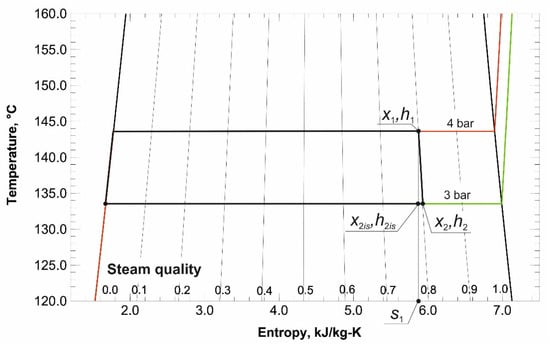
Selected calculated values are presented in Figure 1. A characteristic feature of the analysed cycle is that it is entirely contained in the wet steam region.
Figure 1.
Visualisation of the analysed WSC in a T-s chart.
The power obtained on the expander shaft:
is 0.284 kW (assumed mechanical efficiency: ηm = 0.8).
The generator produces 0.241 kW of electric power (assuming a generator efficiency: hg = 0.85).
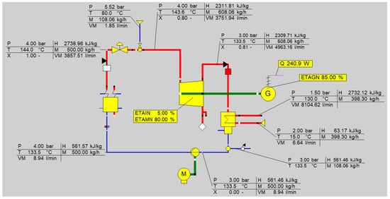
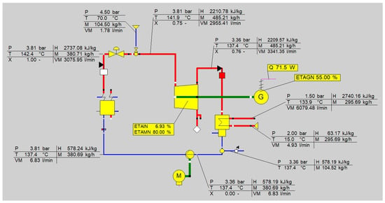
To confirm the correctness of the results, they were compared with the simulation results obtained from the Ebsilon Professional software [38]. The input data were the temperature, pressure, and fluid mass flow rate values used in the above calculations. The simulation results are presented in Figure 2.
Figure 2.
Ebsilon Professional simulation of a wet steam cycle realised using a rotary blower.
The simulation results agree with the results of the calculations—Formulae (1)–(9). This confirms the correctness of the calculation methodology. The slight discrepancies are due only to the accuracy of the enthalpy and entropy determination.
3. CFD Simulations of Steam–Water Mixing in a Pipeline
During the design of the laboratory test stand, provision was made for installing of an injection nozzle on the saturated steam pipeline, in accordance with the test stand diagram (Section 4). The water injection nozzle was placed in the axis of the steam pipeline, which allows for an axially symmetric geometry of the computational domain.
The CFD calculations aimed to determine the required length of the straight pipeline section downstream of the nozzle to achieve the most homogeneous steam–water mixture possible and to produce wet steam with a specified steam quality x1. In particular, the length was selected to avoid regions of excessive local liquid concentration in the pipe cross-section (e.g., a liquid “core” along the pipe axis or zones of high water content near the wall). This could lead to unstable operation of the installation and non-uniform inlet conditions for downstream components. The boundary conditions and flow parameters were selected to match the test stand’s operating conditions. The analyses assumed an absolute pressure of saturated steam at the pipeline inlet of p1 = 5 bar and a steam mass flow rate of = 500 kg/h (0.1389 kg/s). Water was injected at a pressure higher than the steam pressure and at a temperature corresponding to the saturated state. The injection water mass flow rate, , was selected to ensure that the mass and energy balances yielded a mixture with the specified steam quality, x1 = 0.85, under ideal-mixing conditions. The results of the calculations were used to assess whether the straight section provided sufficient equalisation of temperature profiles and liquid phase content. The analysis also examined the possibility of achieving conditions corresponding to the specified steam quality without significant non-uniformity of the mixture across the pipe cross-section.
3.1. Geometry and Computational Mesh
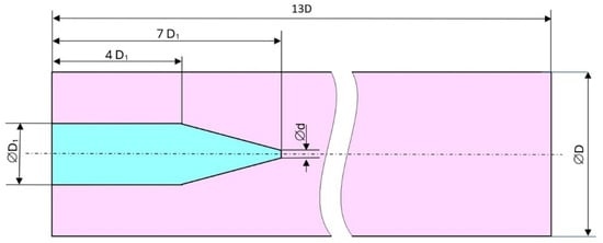
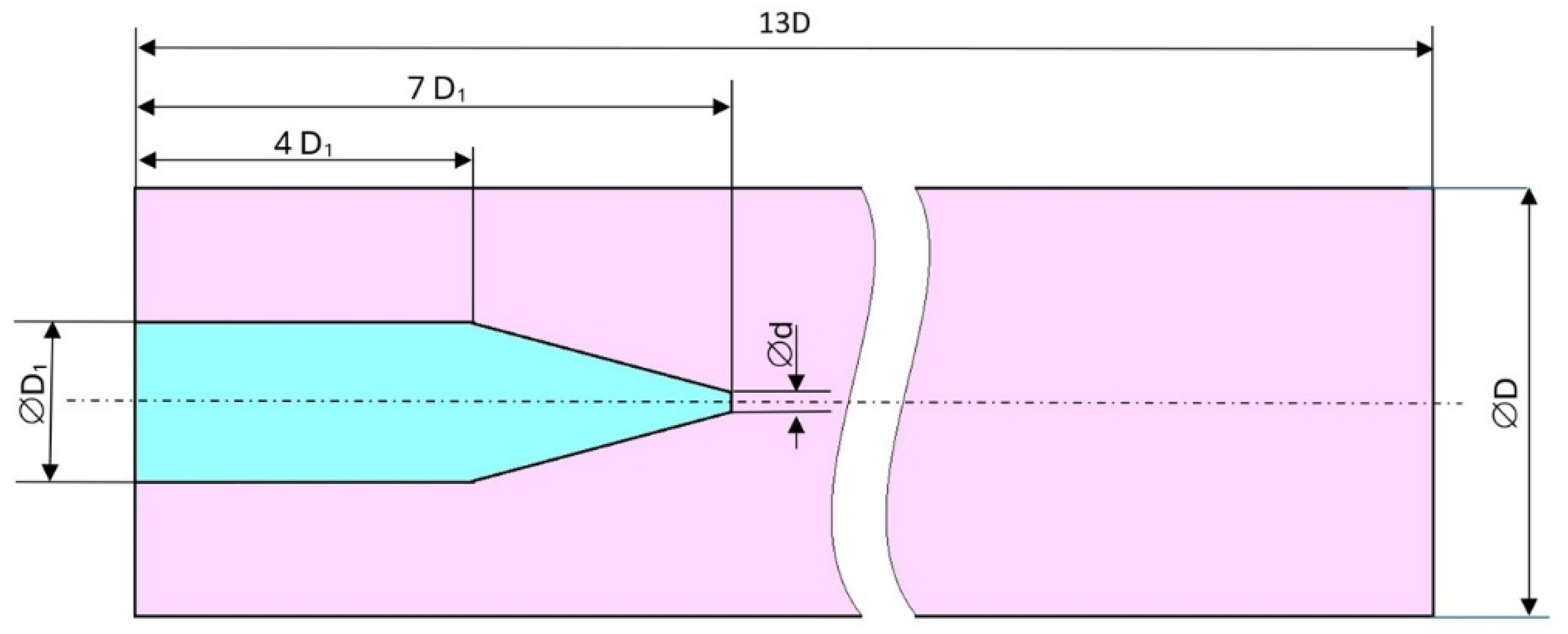
The numerical model was set up as axisymmetric (2D), corresponding to axial water injection into the steam pipeline. The two-dimensional axisymmetric approximation was adopted because the injection-nozzle outlet was positioned concentrically with the main steam pipe, and the water jet was directed along the pipe axis. Thus, the principal geometry and mean flow direction in the analysed mixing section were axisymmetric. The model was intended to determine the engineering mixing length rather than to resolve detailed three-dimensional effects such as local swirl, asymmetric droplet breakup or individual droplet-wall impingement. The computational domain consists of a pipe section of length L = 13D, where D = 43.1 mm is the internal diameter of the DN 40 steam pipe. Water is supplied via a pipe with a diameter of D1 = 16.1 mm to a nozzle converging to a diameter of d = 1.9 mm. Through a cross-section of this diameter, water is injected axially into the main DN 40 pipeline. The geometry with basic dimensions is shown in Figure 3.
Figure 3.
Computational domain geometry.
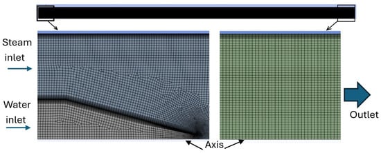
The calculations omit the wall thicknesses of the pipes and nozzle, treating them as boundaries with a specified internal geometry (Figure 3). This approximation is justified because the problem under analysis concerns mixing and the distribution of flow fields within the flow channel. Wall thicknesses, therefore, do not directly affect the geometry of the flow space or the boundary conditions. The model did not account for heat conduction in the wall material. The above simplifications reduce the complexity of the calculations without a significant loss of accuracy in estimating the length of the section required to mix the liquid and gas phases. The domain was discretised using a quad-dominant mesh with approximately 85,000 nodes. In areas where the greatest gradients were expected (around the injection nozzle and immediately downstream of the injection point), a local mesh refinement was applied to capture jet-steam interaction and shear-layer development accurately. An inflation layer consisting of 10 layers and a growth factor of 1.15 was applied to all wall surfaces. This ensured a reliable representation of the flow near the walls and limited the influence of numerical diffusion on the calculated field distributions. The computational mesh with refined areas at the inlet and outlet is shown in Figure 4. The obtained values of the dimensionless distance of the first node from the wall satisfied the condition . This means that the viscous layer immediately adjacent to the walls was included in the calculations. This is consistent with the use of the k–ω SST turbulence model and enables accurate determination of wall stresses and boundary layer development in the analysed flow.
Figure 4.
Computational mesh of the steam-pipe section with the water injection nozzle.
A mesh-dependency study was performed using three computational grids comprising approximately 5.0 × 10⁴, 8.5 ×10⁴, and 1.6 ×10⁵ nodes (Table 1). The comparison was based on the maximum liquid volume fraction, αl,max, evaluated at the 12D cross-section.
Table 1.
Mesh-independence study.
The obtained values were 0.066, 0.062, and 0.061 for the coarse, medium, and fine grids, respectively. Refinement from the medium to the finest grid, therefore, changed αl,max by only approximately 1.6%. Consequently, the grid comprising approximately 8.5 × 10⁴ nodes was considered sufficiently mesh-independent and adopted for the final simulations as a compromise between numerical accuracy and computational cost.
3.2. Model Setup and Convergence Criteria
The CFD calculations were performed under steady-state, two-dimensional axisymmetric conditions using the Mixture model. Steam was treated as the primary phase and liquid water as the secondary phase. Evaporation and condensation were neglected, while the energy equation was solved. At the steam inlet, an absolute pressure of 5 bar and a mass flow rate of 500 kg/h were assumed. The injected water was supplied at the same pressure as the steam and at the saturation temperature corresponding to this pressure, °C. Its mass flow rate was selected to obtain a target steam quality of after ideal mixing. A Pressure Outlet boundary condition was imposed at the pipe outlet. The pipe and nozzle walls were treated as impermeable, no-slip, and adiabatic, while the centreline was defined as the axis boundary condition. Thermophysical properties were based on IAPWS-IF97 data, and turbulence closure was provided by the SST model [39]. This simplification was adopted because both steam and injected water entered the mixing section at the same pressure and the corresponding saturation temperature, while the walls were assumed to be adiabatic. Thus, no significant thermal disequilibrium was imposed at the inlet, and the mixing process was governed primarily by turbulent shear and interphase momentum exchange. It should also be noted that neglecting evaporation and condensation does not necessarily lead to an underestimation of the mixing length, since local evaporation may reduce the liquid fraction and accelerate the decay of the liquid-rich core. Therefore, the obtained length of 12D should be regarded as appropriate for the hydrodynamic conditions analysed in the present study. A fully coupled non-equilibrium phase-change model may modify the local phase distribution; therefore, the 12D value should be interpreted as applicable to the hydrodynamic conditions and modelling assumptions adopted in the present study. For the present case, the governing equations of the Mixture model include the mixture continuity equation:
the mixture momentum equation:
and the transport equation for the liquid-phase volume fraction:
The mixture density and mass-averaged velocity are defined as:
where r, m, a, and v denote density, dynamic viscosity, volume fraction and velocity, respectively; the subscripts mix, k, l and dr denote the mixture, phase k, liquid phase and drift velocity, respectively. Under steady-state conditions, the time-derivative terms vanish. Pressure–velocity coupling was implemented using the SIMPLE algorithm. The pressure field was interpolated using the PRESTO! scheme. The momentum and energy equations, turbulence quantities, and phase fractions were discretised using second-order schemes. To accelerate convergence in steady-state calculations, the pseudo-time method (Local Time Step) was used.
Convergence was assessed using criteria commonly adopted in engineering CFD calculations. The residual thresholds were set to 10−4 for the continuity, momentum, turbulence and phase-volume-fraction equations and to 10−6 for the energy equation. In addition, the overall mass-flow imbalance between the inlets and outlet was required to remain below 0.1%. During the iterative solution process, the residuals reached their minimum values and stabilised at a plateau. The solution was considered converged only after the prescribed residual criteria were satisfied, the monitored flow quantities reached stable values, and no further appreciable changes in the principal mixing indicators were observed. These convergence requirements were considered adequate for the present steady-state engineering analysis, whose primary objective was to determine the required steam-water mixing length.
3.3. Computation Results
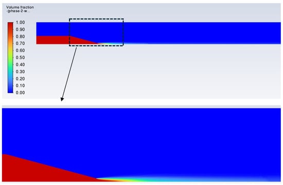
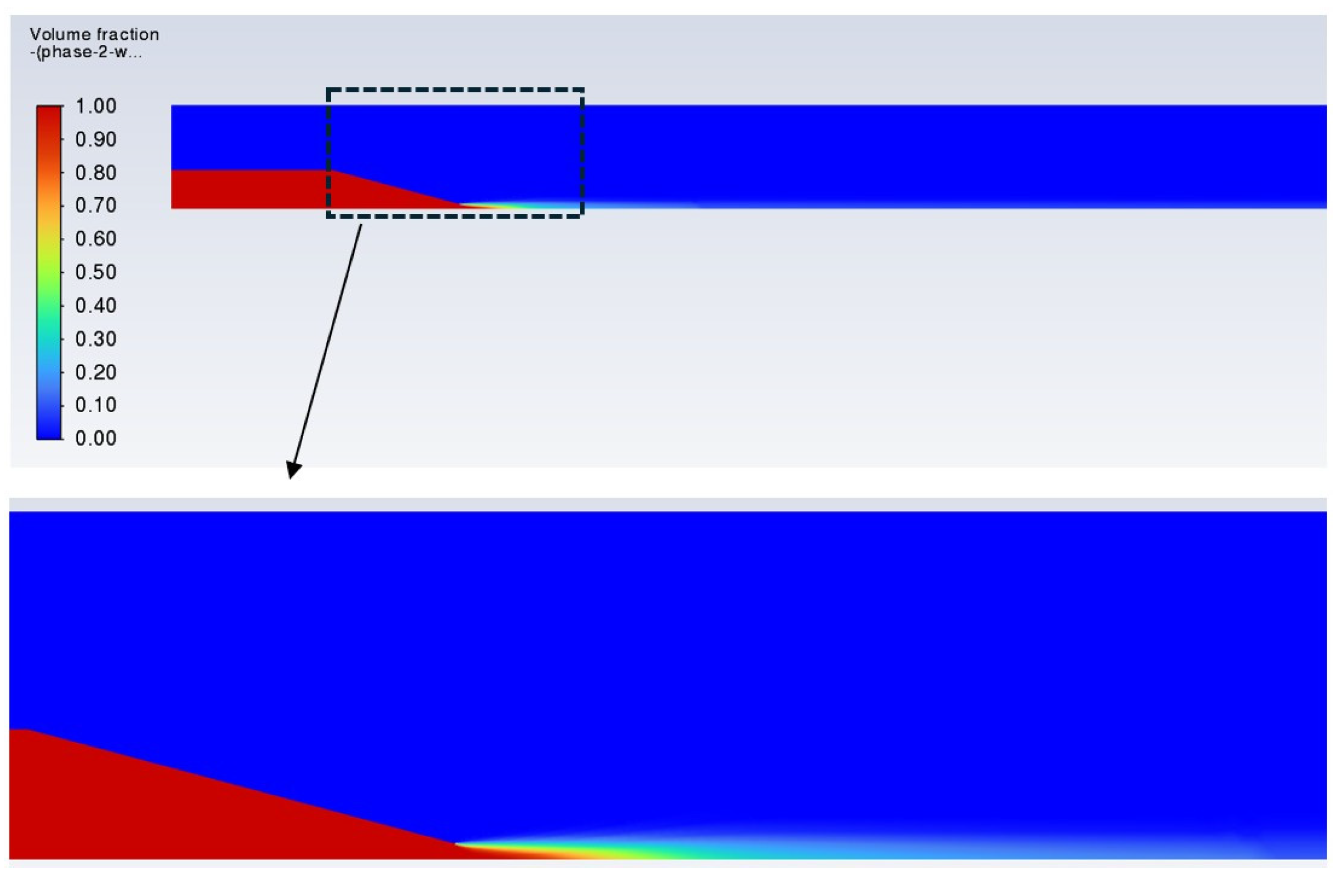
CFD calculations were performed for the mixing of steam and water in an axially symmetric domain corresponding to the axial injection of water into a steam pipeline. The primary qualitative result is the distribution of the local volume fraction of the liquid phase al (phase-2: water). It allows for the assessment of the formation of a liquid jet and its gradual dispersion within the steam flow.
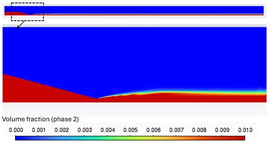
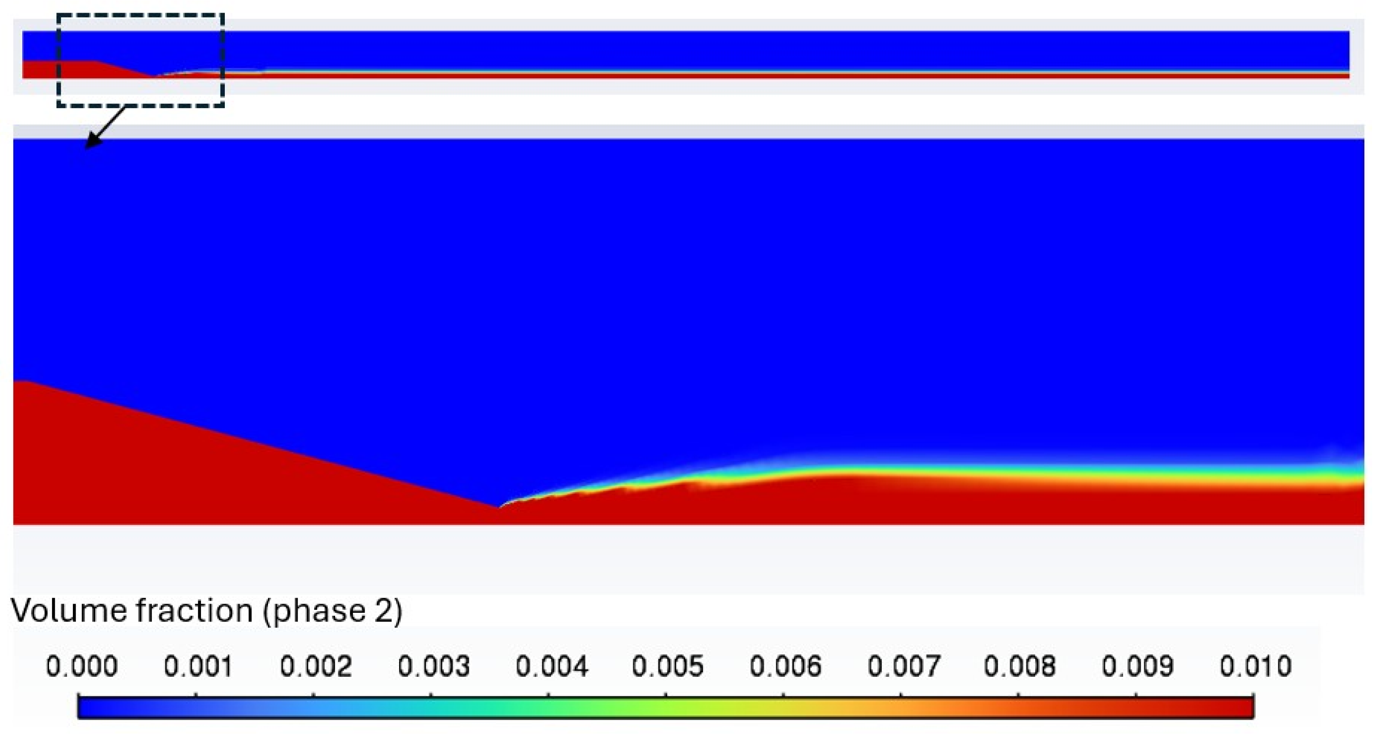
Figure 5 presents the al contours on a scale of 0–1. The continuous liquid-phase distribution results from the Eulerian formulation of the Mixture model, in which the phases are represented by continuous volume-fraction fields rather than by individually tracked droplets. Due to axial injection, a liquid-rich core initially forms along the pipe axis and disperses gradually through turbulent shear and interphase momentum exchange. The presence of a liquid region in the injection duct and the formation of a distinctly inhomogeneous al field immediately downstream of the nozzle outlet were clearly confirmed. In this context, a large portion of the main pipeline is characterised by very low al values. Therefore, to better visualise the mixing process, Figure 6 shows a reduced scale range of 0–0.1. The reduced scale highlights the gradual mixing, which is less visible in Figure 5 because of the full 0–1 colour scale. The presence of a liquid region in the injection duct and the formation of a distinctly inhomogeneous al field immediately downstream of the nozzle outlet were clearly confirmed. In this context, a large portion of the main pipeline is characterised by very low al values. Therefore, to better visualise the mixing process, Figure 6 shows a reduced scale range of 0–0.1. This allows better visualisation of the area with a low liquid fraction, as well as the gradual decay of phase non-uniformity along the pipe length. The local liquid volume fraction was used to analyse the results. This is because, in a two-phase model, it is a direct quantity calculated by the solver and best illustrates the spatial distribution of the phases (e.g., the presence of a liquid core). Mass fractions, on the other hand, can be misleading because of the large density difference between steam and water.
Figure 5.
Distribution of the liquid volume fraction al in the mixing region downstream of the injection nozzle (colour scale range is 0–1).
Figure 6.
Distribution of the liquid volume fraction al in the mixing region downstream of the injection nozzle (colour scale range is 0–0.1).
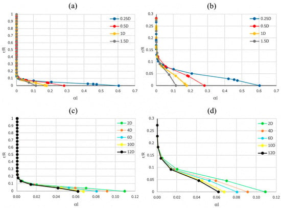
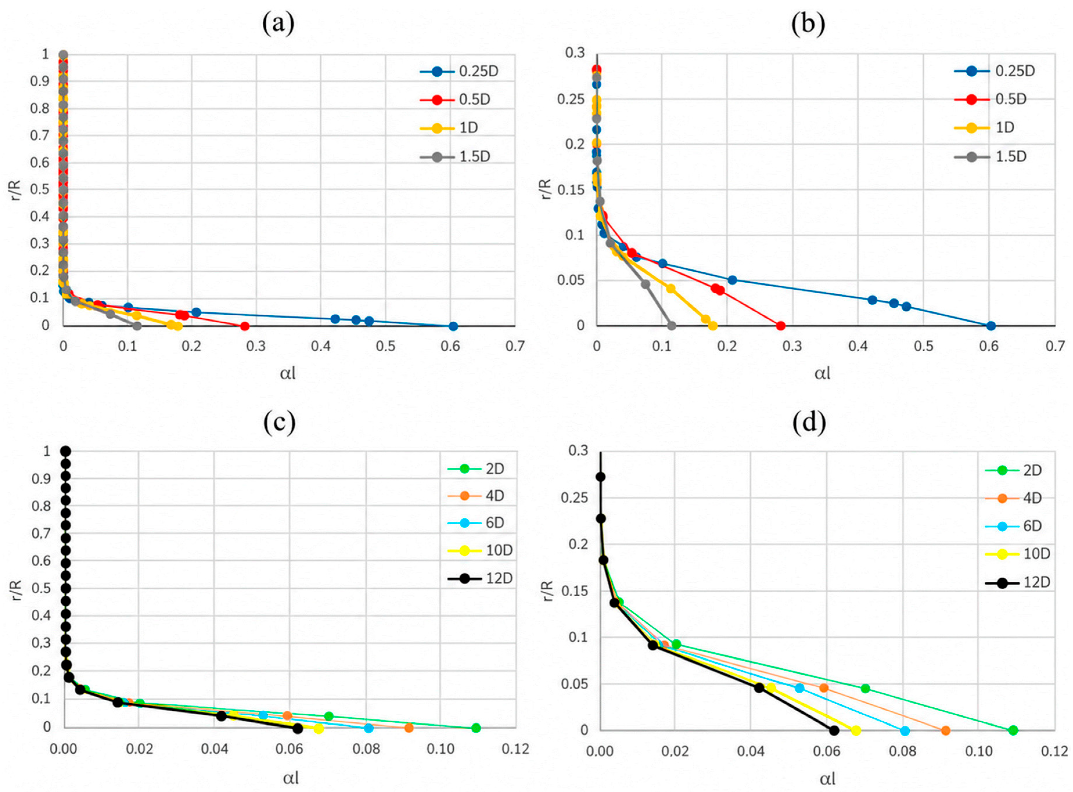
To quantitatively assess the mixing of water and steam, a set of control cross-sections was defined along the main pipeline. These cross-sections were located at distances z = 0.25D, 0.5D, 1D, 1.5D, 2D, …, 12D from the nozzle outlet (Figure 7). For each cross-section, the radial profile of the volume fraction of the liquid phase al was determined as a function of the normalized radius r/R (where R = D/2 represents the inner pipe radius, r/R = 0 corresponds to the central longitudinal axis, and r/R = 1 corresponds to the inner pipe wall), as shown in Figure 8.
Figure 7.
Control cross-sections along the pipe length.
Figure 8.
Distributions of the liquid volume fraction al at several pipe cross-sections: (a) cross-sections z/D = 0.25–1.5 (full radius, 0 ≤ r/R ≤ 1); (b) same as (a), with a zoomed-in view near the centreline (0 ≤ r/R ≤ 0.3); (c) cross-sections z/D = 2–12 (full radius, 0 ≤ r/R ≤ 1); (d) same as (c), with a zoomed-in view near the centreline (0 ≤ r/R ≤ 0.3).
The profiles obtained directly downstream of the nozzle (0.25D–1.5D) indicate strong non-uniformity. Its maximum occurs at the axis, which corresponds to the axial liquid jet. For r/R ≳ 0.1, the values of al decrease rapidly, and a significant portion of the cross-section remains nearly “dry”. As the distance from the injection point increases (2D–12D), a gradual decay of the liquid core is observed. The profiles flatten, and the maximum al along the axis, as well as the size of the region of increased liquid content, decrease. At the same time, even at a distance of 12D, an increased liquid content is still present near the axis. This means that the mixing process under axial injection conditions is gradual and requires a finite length of straight pipe to achieve the desired level of homogeneity.
Based on the al profiles in the control cross-sections, two practical metrics to quantify mixing were defined (Table 2). The first criterion was the maximum value of the liquid volume fraction in the cross-section, al,max, which describes the “wettest” point in the flow. The acceptance criterion was set at al,max < 0.07, corresponding to the limit of local over-wetting along the pipe centreline. As shown in Table 2, at a distance of 12D, al,max = 0.062 was obtained, which satisfies the adopted criterion.
Table 2.
Results of the maximum and mean liquid volume fraction at the control cross-sections.
The second criterion was a geometric measure of the liquid core based on the radius r0.05, defined as the radius at which al = 0.05. Using r0.05, the fraction of the cross-sectional area occupied by the region with al > 0.05 was estimated as A0.05/A = 100·(r0.05/R)2. Here, A0.05 denotes the cross-sectional area where the local liquid volume fraction exceeds 0.05 (i.e., the liquid-core region with al > 0.05), whereas A is the total cross-sectional area of the pipe (A = πR2). An acceptance threshold of A0.05/A < 0.1% was adopted, indicating that the region of elevated liquid content is confined to a very narrow core and does not form an extensive “wet” zone across the cross-section. According to Table 2, 12D r0.05/R = 0.027, corresponding to A0.05/A ≈ 0.07%, which also satisfies the second criterion. Consequently, a straight-pipe length of 12D can be considered sufficient to achieve an acceptable level of homogenisation of the liquid volume-fraction field under the injection conditions analysed. The adopted thresholds should be regarded as engineering design criteria rather than universal physical limits. The resulting straight-pipe length of 12D was subsequently implemented in the experimental test stand. During the experiments, stable wet-steam operation was achieved with this configuration, although the local liquid volume-fraction distribution was not measured experimentally.
4. Test Stand
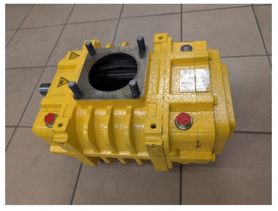
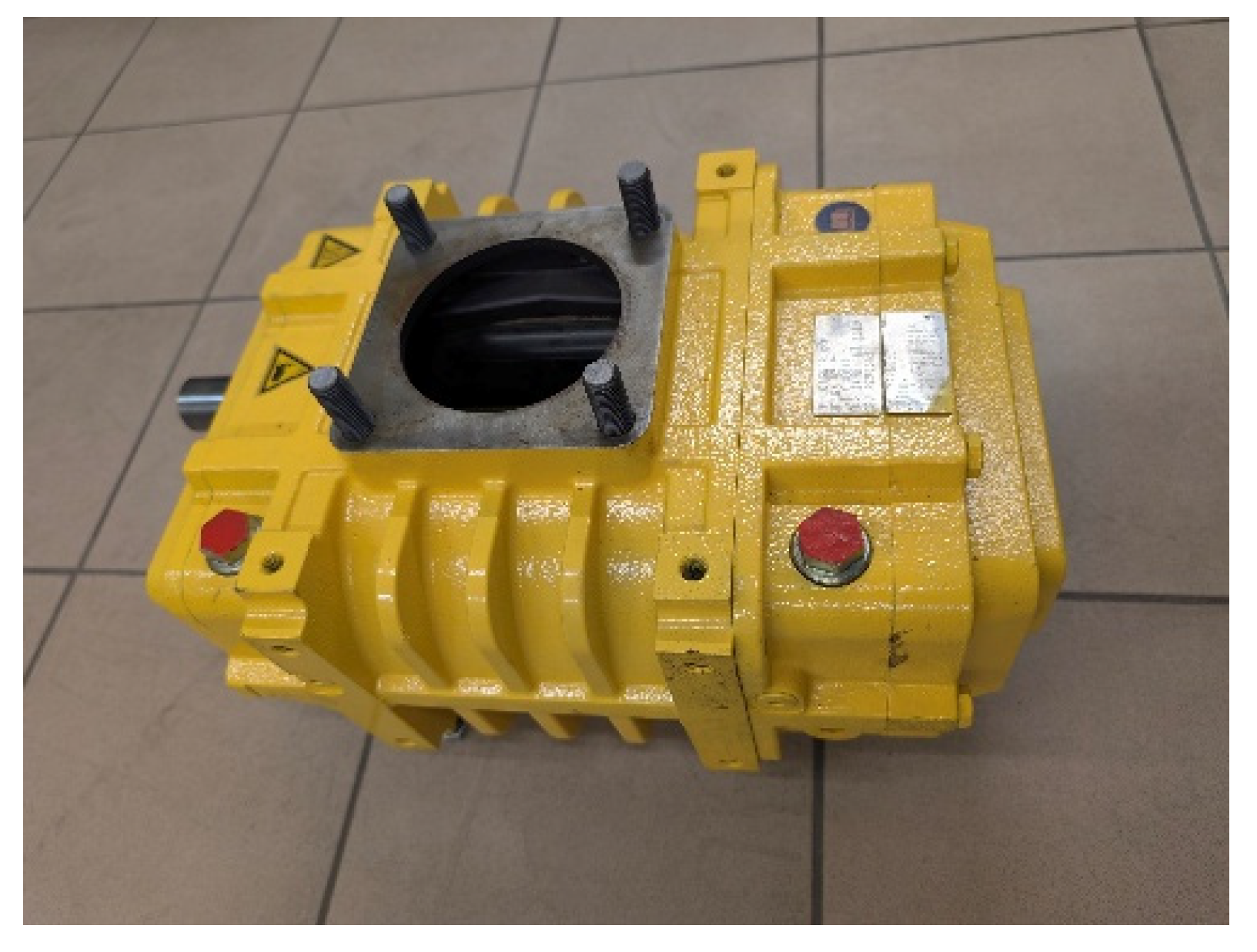
Based on the results from Section 2, the rotary blower was selected for testing. It is presented in Figure 9, and its parameters are listed in Table 3. The tests were performed during blower operation in reverse cycle (as an expander), realising the WSC (Section 5). The blower is oil-free. The rotary blower was represented in the Ebsilon model as a lumped thermodynamic expander; therefore, its internal rotor geometry and chamber dimensions were not included in the simulation.
Figure 9.
View of the tested rotary blower (KAESER OMEGA 42P).
Table 3.
Selected parameters of the rotary blower [40].
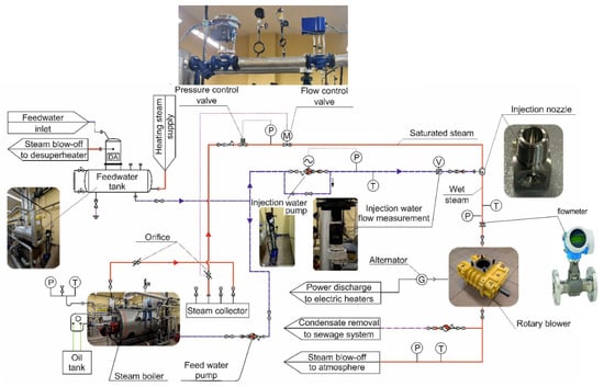
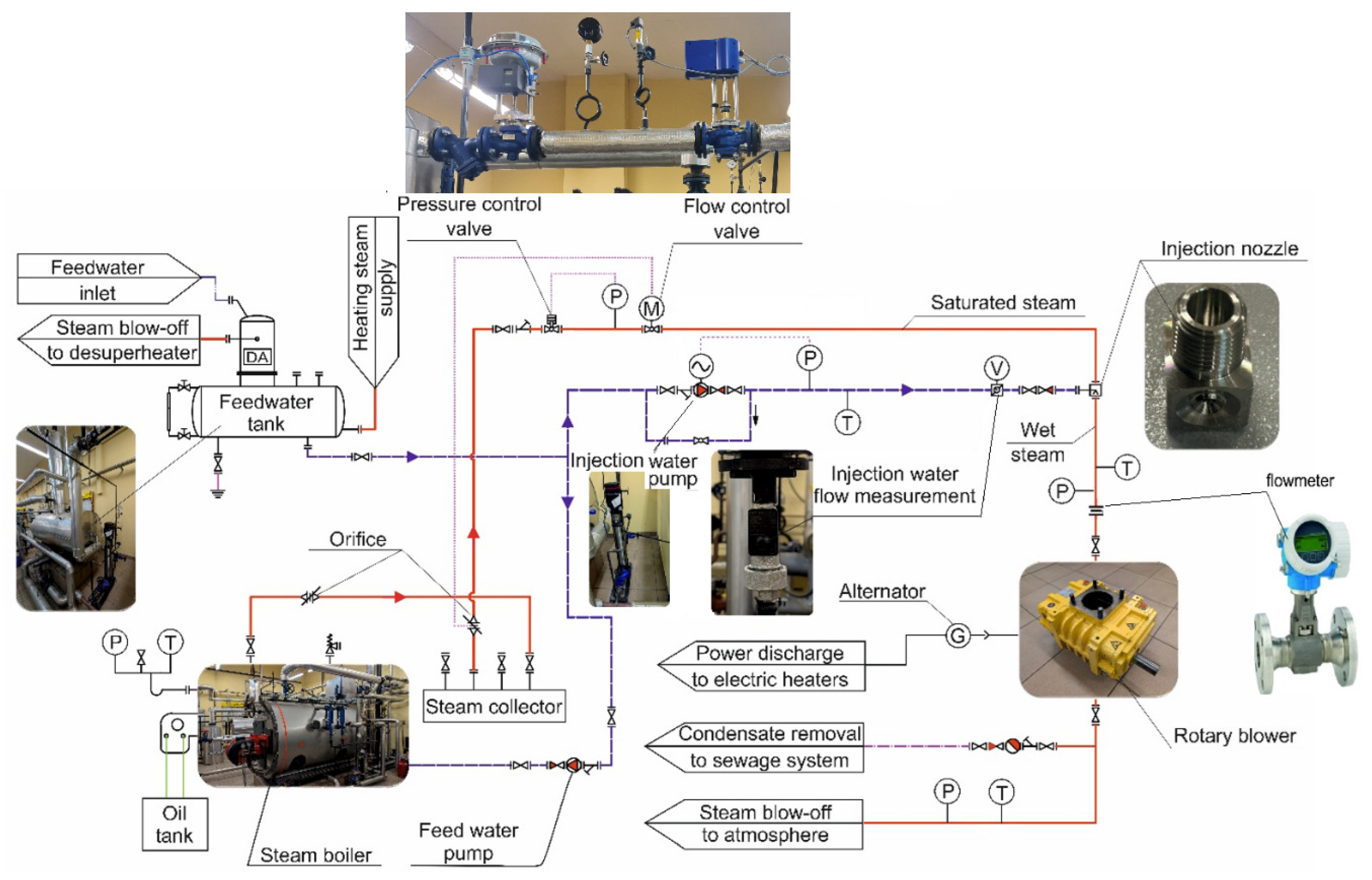
A test stand for experimental verification of the rotary blower’s operation as an expander was built in the Department of Energy’s laboratory at the Cracow University of Technology. It is an extension of the existing stand equipped with an oil boiler with the necessary fittings. A diagram of the entire test stand is shown in Figure 10.
Figure 10.
Schematic diagram of the experimental test stand, including the boiler, feedwater tank, injection-water pump, injection nozzle, straight mixing section, rotary expander, generator and the main measurement points. P—pressure measurement; T—temperature measurement; V—volume flow measurement; M—mass flow measurement.
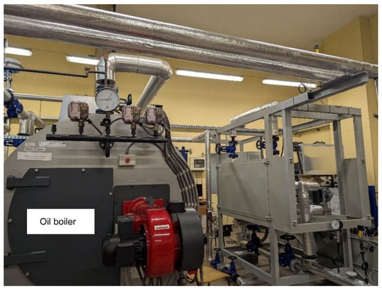
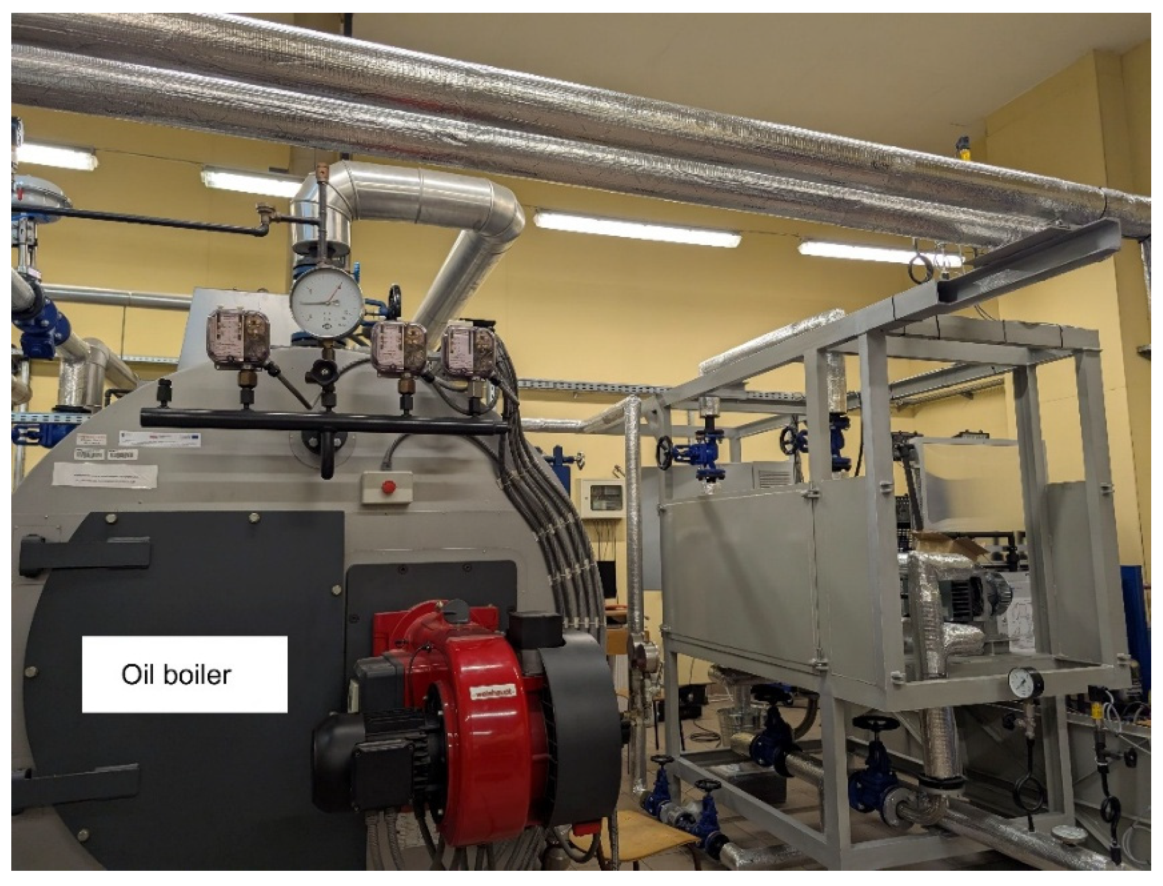
The available boiler (Figure 11) generates 700 kg/h of saturated steam at 1 MPa under nominal conditions.
Figure 11.
Oil boiler with the expander testing stand.
To obtain wet steam, the stand is additionally equipped with an injection water pump, a measurement of the injection water mass flow rate, and an injection nozzle mounted on the steam pipeline (Figure 12). To obtain a uniform mixture of steam and water, the required length of the straight pipe downstream of the nozzle was determined based on the modelling results presented in Section 3. The injection water is taken from the feedwater tank. The water temperature and pressure are measured. Because only a small water mass flow rate is required at the stand, a bypass is necessary to ensure the pump’s safe operation (Figure 10).
Figure 12.
Injection nozzle mounted in the saturated steam pipeline.
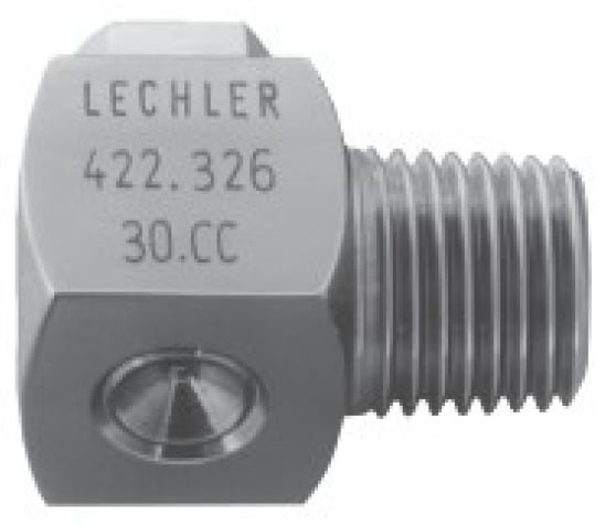
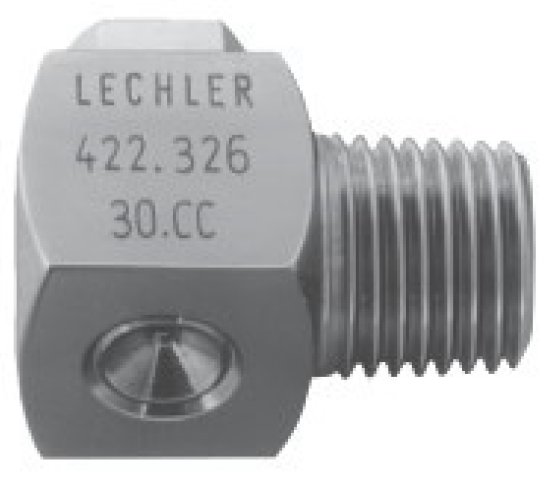
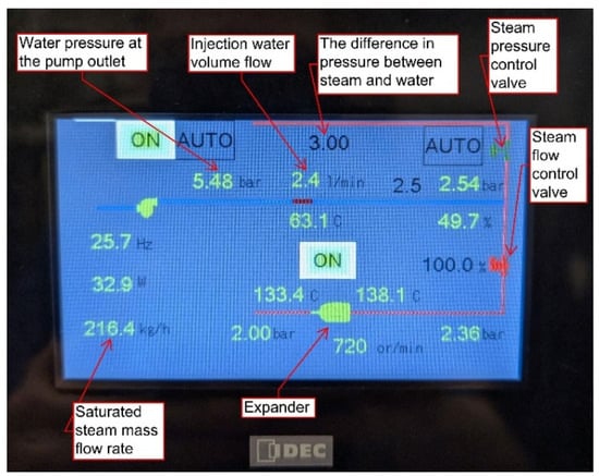
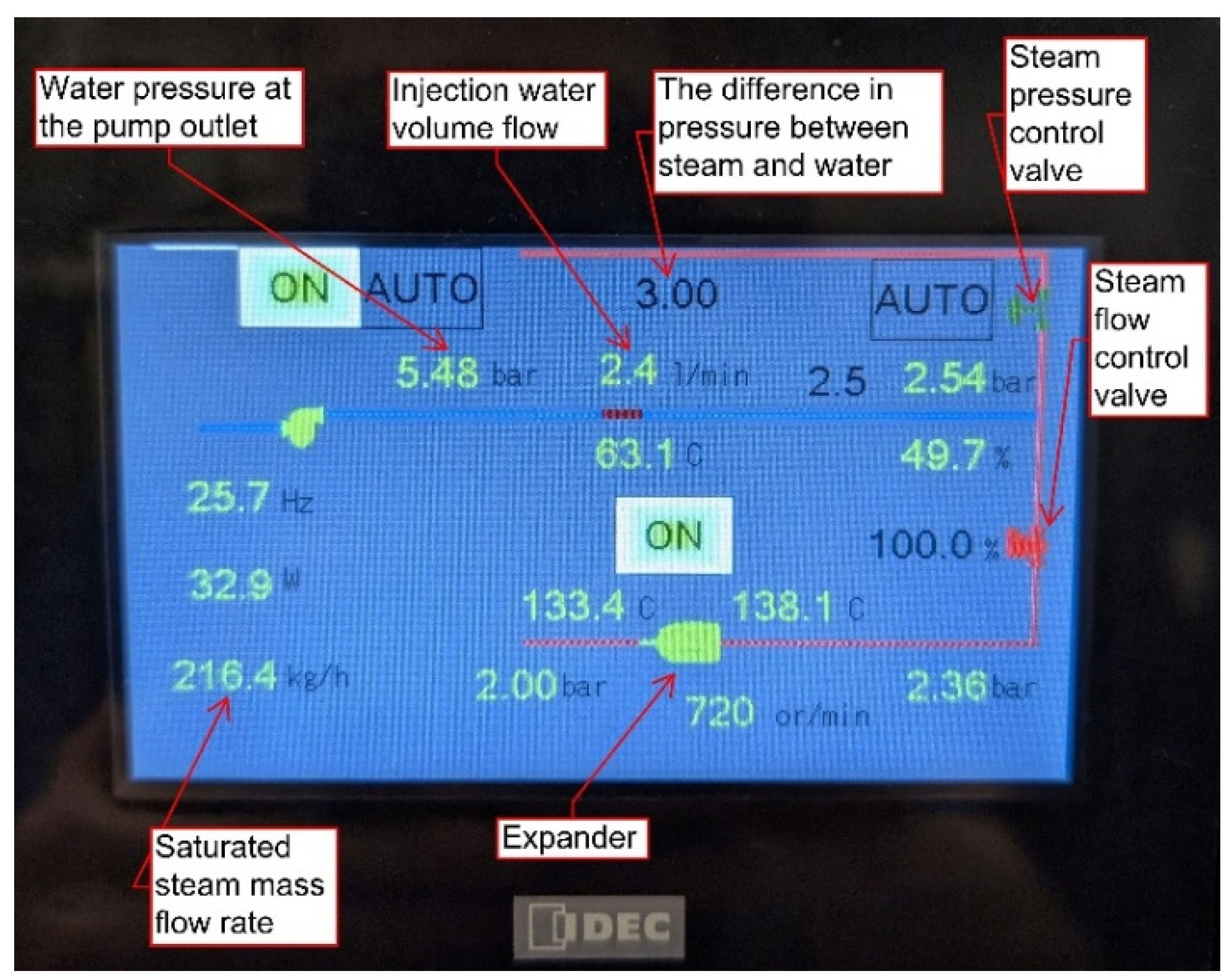
The nozzle used features a design with no built-in elements. It ensures an angular water supply and uniform spraying. The injection water mass flow rate was adjusted by setting the pressure difference between the saturated steam pressure and the injection water pressure. The difference was set on an active LCD (Figure 13). On the display, it is also possible to set the expander inlet steam pressure and the steam control valve opening rate.
Figure 13.
View of the screen enabling setting and reading instantaneous values (with description of selected quantities).
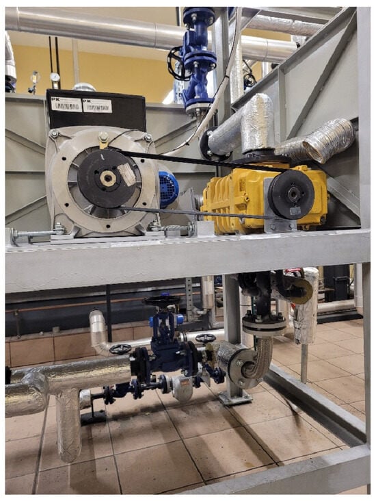
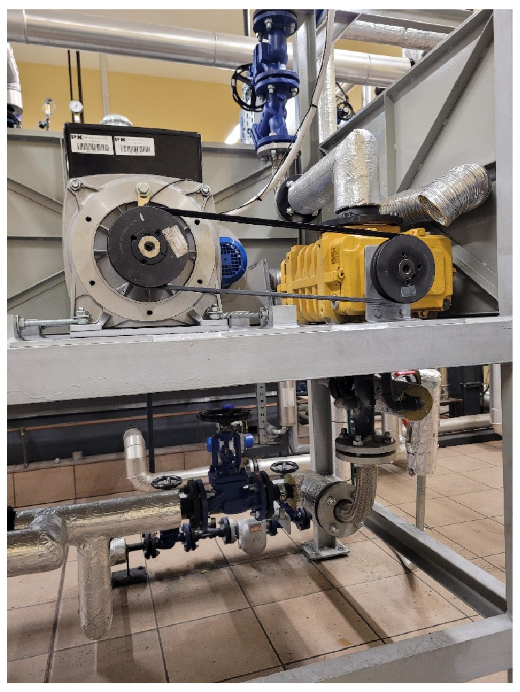
The right side of Figure 11 shows the stand extension used to test the performance of expanders driven with saturated or wet steam. For safety reasons, the expander with the generator is built in a steel sheet casing. A view of the tested blower, connected to the generator via V-belts, is shown in Figure 14 (all components are placed inside the casing). The electric power produced by the generator is delivered to electric heaters. The basic parameters of the selected generator are listed in Table 4. The parameters (especially power) are substantially different from those required as estimated in Section 2. This is due to plans to use the generator in further studies of other expanders characterised by higher expansion ratios, thereby achieving higher power.
Figure 14.
View of the rotary blower connected to the generator.
Table 4.
Selected parameters of the ALTERNATOR E1S13S a/4 [41].
The generator’s efficiency varies with the power generated at its terminals. Based on the efficiency curve [41], a formula was developed that allows for the real-time calculation of this efficiency:
The test stand is equipped with a data acquisition system. The measured quantities include, for example, the wet-steam temperature and pressure histories at the expander inlet and outlet, as well as the mass flow rates of saturated steam and injection water. Also measured are the generator’s rotational speed and the power it generates. The expander isentropic efficiency and the steam quality are calculated.
5. Selected Measurement Results and Their Analysis
The measurements were carried out at a gauge pressure of 3 bar set in the boiler. A data acquisition system collected the results after the boiler had been preheated, i.e., approximately 2 h after start-up. Such a long time was required, especially to heat the feedwater and stabilise the temperature of the pipelines and the expander. For the first several minutes of the measuring cycle, the expander was fed with saturated steam.
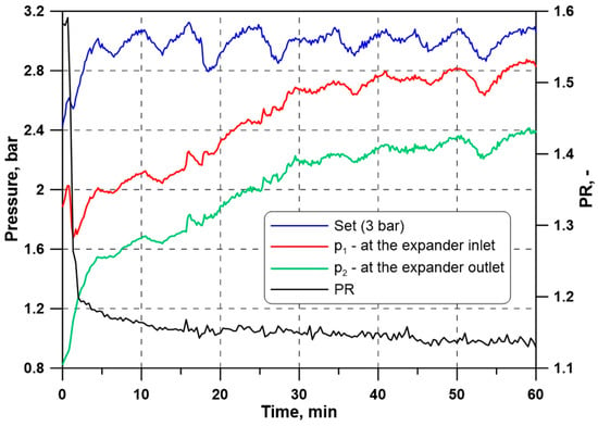
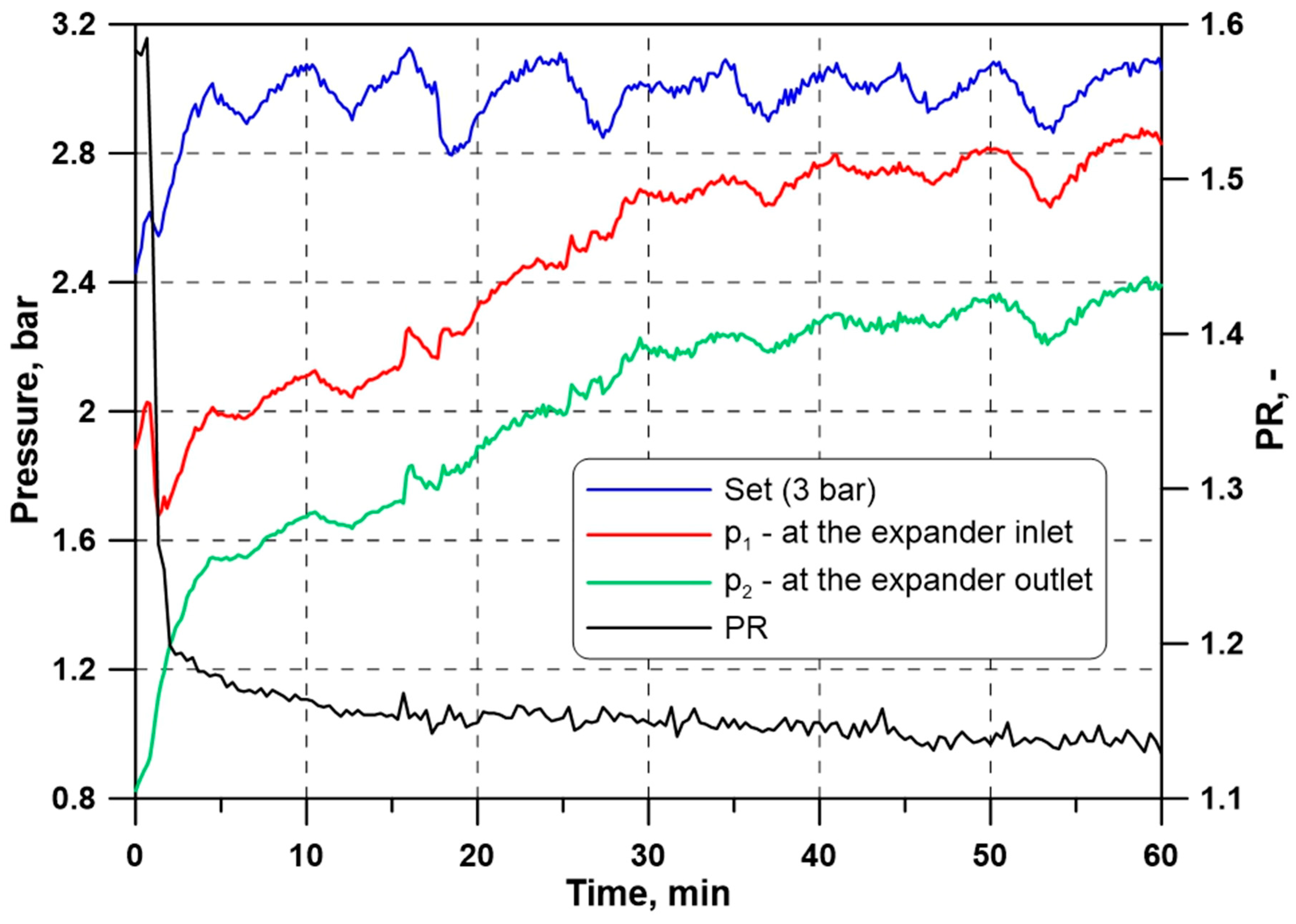
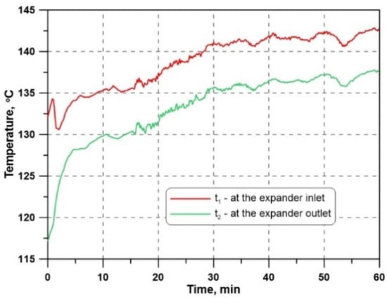
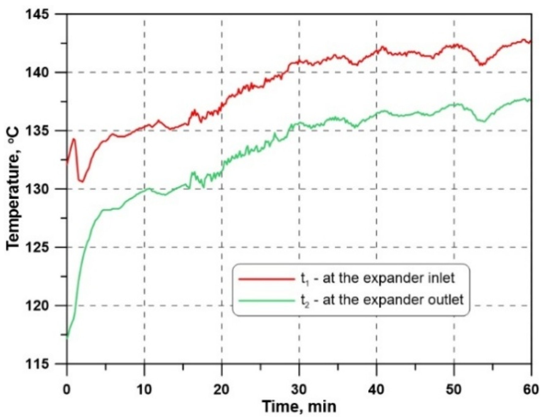
Figure 15, Figure 16, Figure 17, Figure 18, Figure 19, Figure 20 and Figure 21 display selected results of the measurements and calculations for the steam gauge pressure of 3 bar, as set on the boiler pressure control. The measured histories of gauge pressure and temperature are illustrated in Figure 15 and Figure 16, respectively. The pressure values presented in Figure 15 are gauge pressures, whereas all pressures used in the thermodynamic calculations and process simulations are absolute pressures. As shown in Figure 15, the pressure drop from the boiler to the expander inlet is approximately 0.5 bar. Such a large drop is caused by several factors. These primarily include the valves installed in the flow path to regulate the steam pressure and mass flow rate, as well as linear and local pressure losses. The control valves have the greatest impact. A fully open control valve can cause a pressure drop of 0.1–0.3 bar at a steam mass flow rate of approximately 450 kg/h. Linear and local pressure losses depend mainly on the flow velocity, which was approximately 35 m/s at the mass flow rate mentioned above and at a steam quality of 0.75.
Figure 15.
Measured histories of steam gauge pressure and calculated history of the PR values.
Figure 16.
Measured histories of steam temperature.
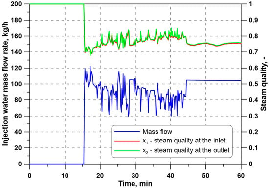
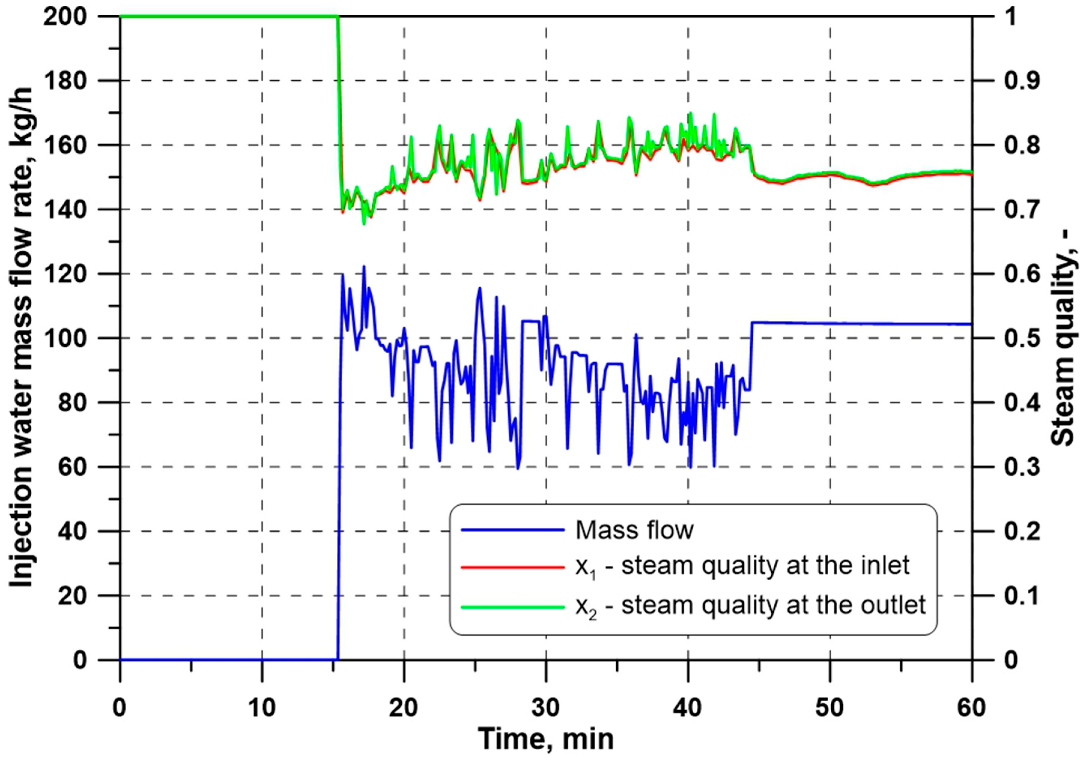
Figure 17.
Calculated histories of the steam quality at the expander inlet and outlet, and injection water mass flow rate.
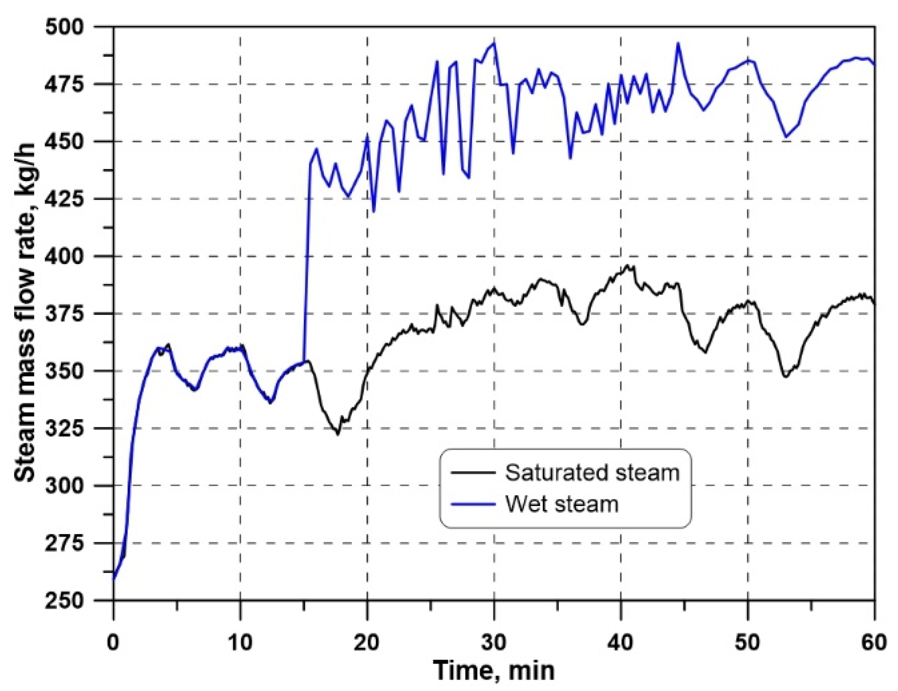
Figure 18.
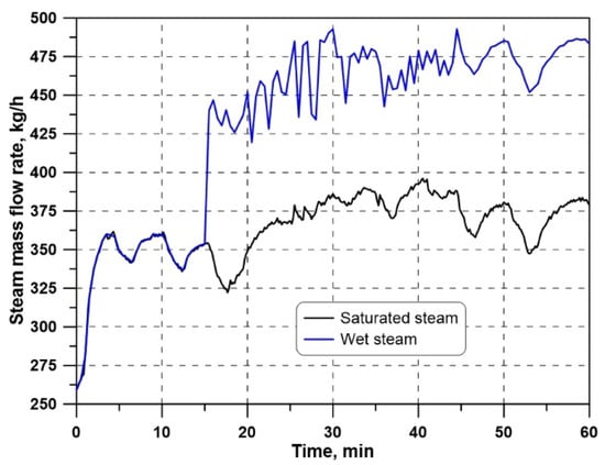
Histories of the steam mass flow rates: measured (saturated) at the boiler outlet and calculated (wet) at the expander inlet.
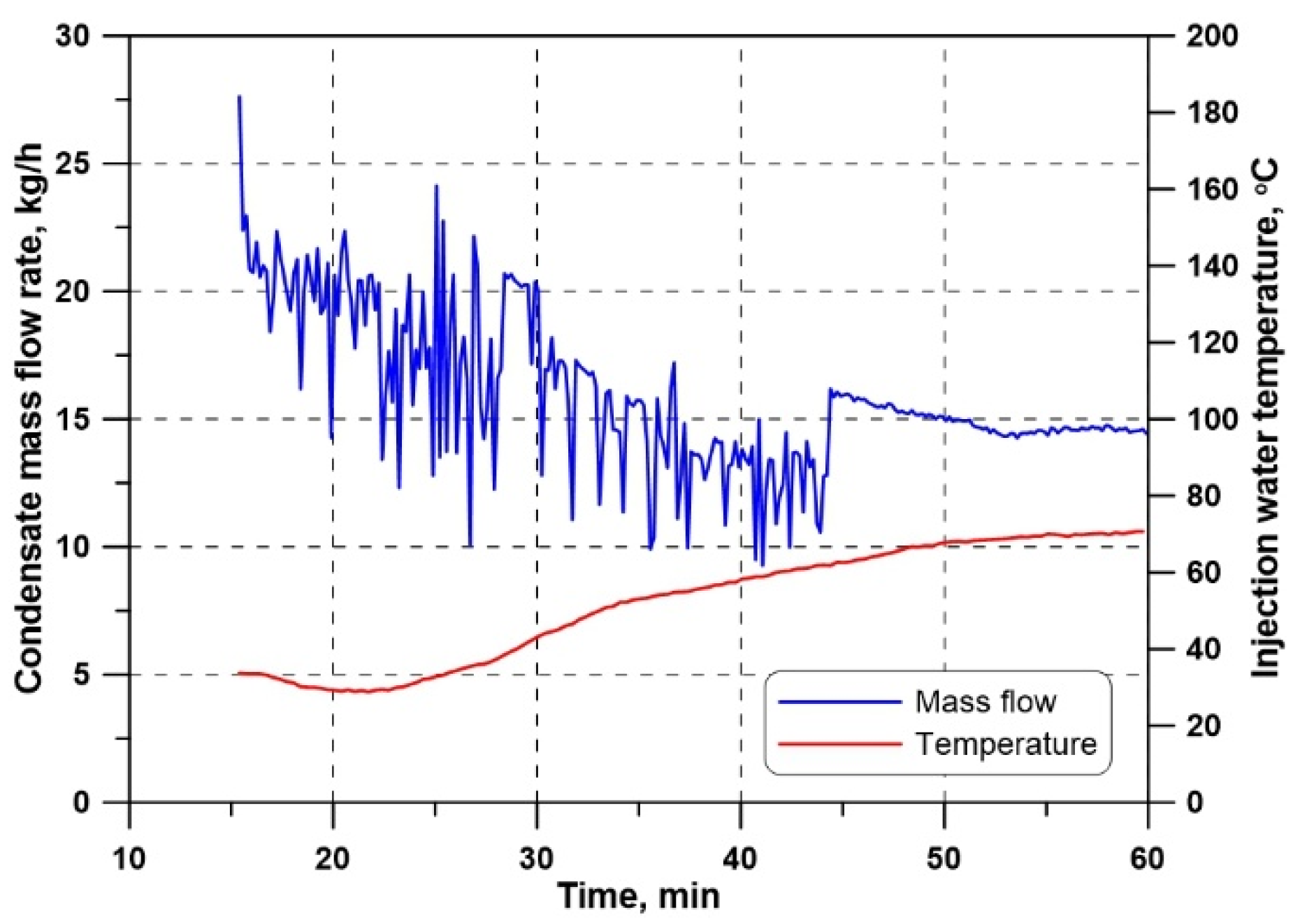
Figure 19.
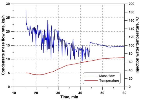
Measured history of the injection water temperature and calculated history of the condensate mass flow rate.
Figure 20.
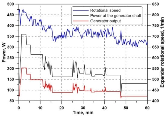
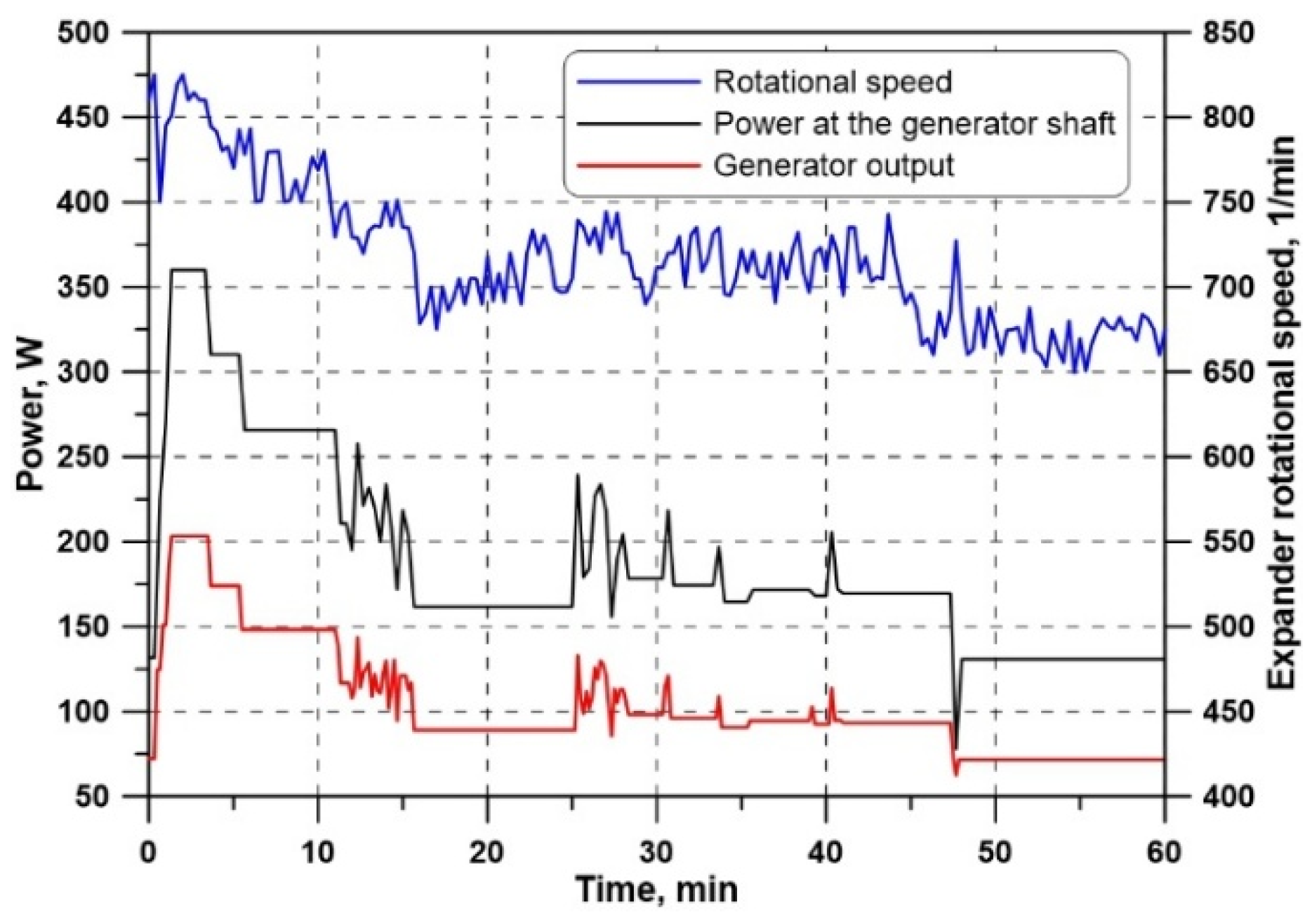
Measured histories of changes in electric power and the expander rotational speed; calculated history of changes in power at the generator shaft.
Figure 21.
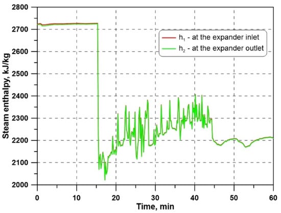
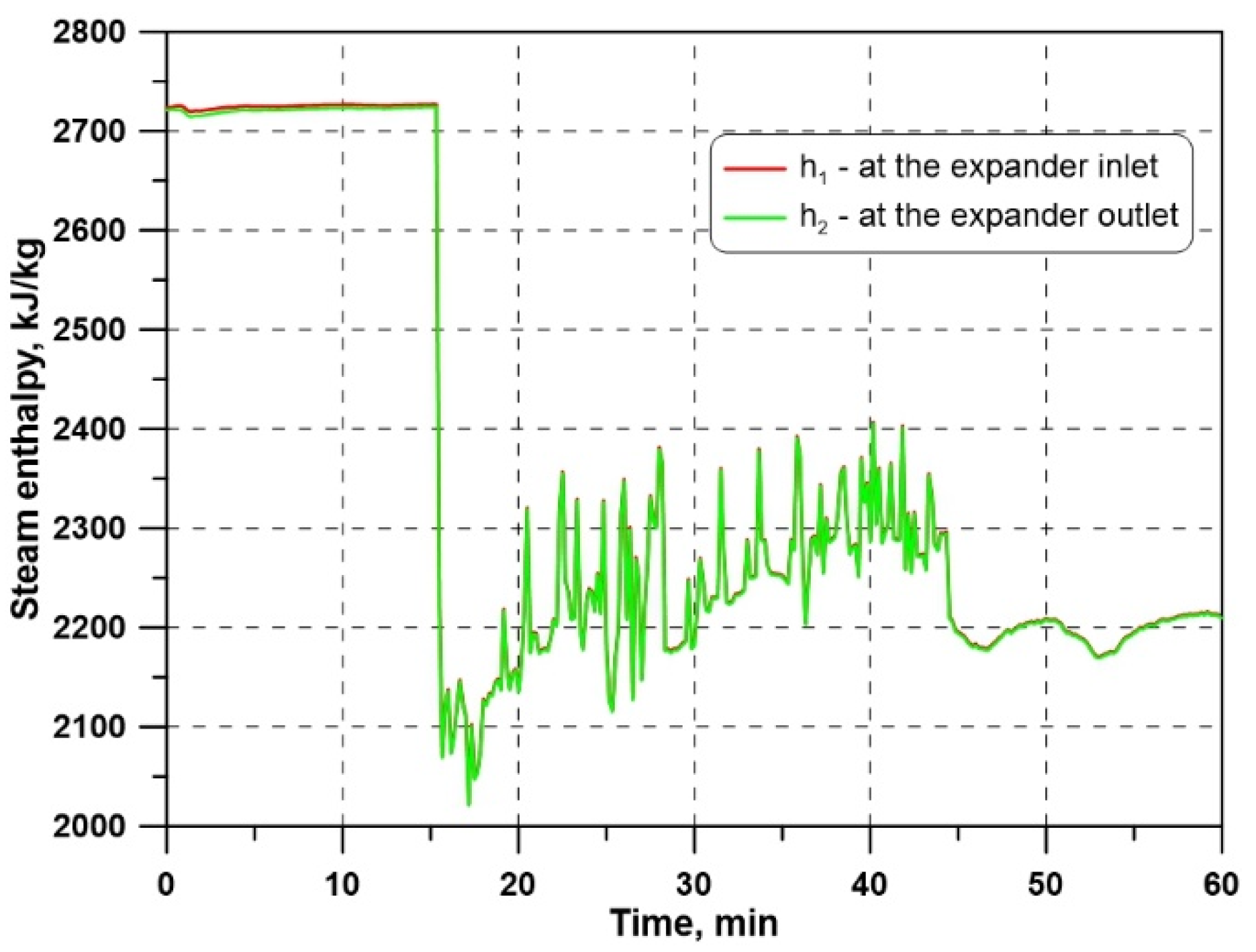
Calculated histories of the steam enthalpy at the expander inlet and outlet.
The calculated PR values, also shown in Figure 15, are low, hovering around 1.15.
Figure 15 and Figure 16 show that steady-state conditions were achieved after approximately 30 min of measurement. The pressure drop from the value set on the boiler pressure control (blue line in Figure 15) to the expander inlet (red line) is due to the pressure losses from the boiler to the expander. Throughout the measurement cycle, the difference between the expander inlet and outlet pressures is small (approximately 0.5 bar). This confirms the low pressure ratios obtained for this expander type.
For approx. the first 15 min of the measuring cycle, the expander was fed with saturated steam. Next, wet steam generation was initiated by injecting feedwater into the saturated steam (Figure 17 and Figure 18). The injection water volume flow, pressure, and temperature were measured on the test stand. Based on this, the water mass flow rate was calculated (Figure 17). The same figure also illustrates the calculated histories of the steam quality, which range from approximately 0.7 to approximately 0.83 at the expander inlet and outlet. Slightly higher oscillations in steam quality are observed at the expander outlet.
The steam quality values at the expander inlet are calculated based on the measured history of the saturated steam mass flow rate (Figure 18), the calculated injection water mass flow rate (Figure 17), and the calculated mass flow rate of condensate (Figure 19):
The condensation of a small mass flow of saturated steam results from absorbing the heat required to raise the injection water temperature to the saturation temperature. Figure 19 also shows the temperature history of the injected water. Lower water temperatures correspond to a higher condensate mass flow rate.
The effect of heat loss on the environment through the pipe walls during steam mixing and flow was not accounted for. The steel steam pipes, with an internal diameter of 40 mm, were well insulated with 50 mm-thick mineral wool. Ignoring the negligible thermal resistance of the pipe walls and the convective resistance from the steam to the pipe wall, the unit linear heat loss was estimated at approximately 22 W/m. Assuming a local heat loss of 10%, the total heat loss was calculated to be approximately 600 W for a 25 m-long pipeline. Consequently, the amount of condensed steam is approximately 1 kg/h. This is a negligible value compared with the mass flow rates of the injection water (Figure 17) and has no effect on the change in the steam quality at the expander inlet.
The steam quality at the expander outlet was calculated using Equation (8), which required the wet-steam enthalpy at the outlet. The values of the enthalpy were determined by means of the following formula:
The results of the power measurement at the generator terminals are shown in Figure 20. The power values ranged from approximately 70 W to approximately 130 W (when the expander was driven by wet steam). The generator’s efficiency, calculated using Equation (14), was low, at approximately 55%. Due to a lack of data (both from the manufacturer and the literature) on the mechanical efficiency of the tested rotary blower, ηm = 0.8 was assumed in the calculations. By substituting these values in Equation (16), the wet steam enthalpy values at the expander outlet were determined, as shown in Figure 21. Formula (3) was used to calculate the history of the wet steam enthalpy at the expander inlet, which is also shown in Figure 21. The curves representing the changes in these enthalpies are almost identical, which is due to the small pressure differences p1-p2 (Figure 15). A significant decrease in enthalpy (Figure 21) and in power (Figure 20) was observed when the expander was fed with wet steam. The expander was supplied with saturated steam for approximately 15 min, after which wet steam appeared at its inlet.
The measured expander rotational speed is shown in Figure 20. The values given in Table 3 (Section 4) are manufacturer data for the KAESER OMEGA 42 P blower operating in its intended blower mode. The manufacturer specifies a rated volumetric flow rate of 15.91 m3/min and a maximum allowable rotational speed of 4800 min−1. However, no design-point rotational speed is specified in the manufacturer’s documentation. In the present study, the machine was used in reverse operation as a wet-steam expander. As can be seen from Figure 20, the measured rotational speed was approximately 650–800 min−1. Therefore, the machine operated at only about 14–17% of its maximum permissible rotational speed. Since the manufacturer does not specify the design-point rotational speed for blower operation, it is not possible to determine this point for operation as a wet-steam-driven expander. Future studies will aim, among other things, to increase the rotational speed by modifying the transmission ratio.
The power history at the generator shaft, illustrated in Figure 20, was calculated using the generator’s efficiency, as determined using Equation (14).
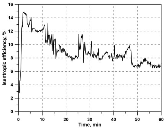
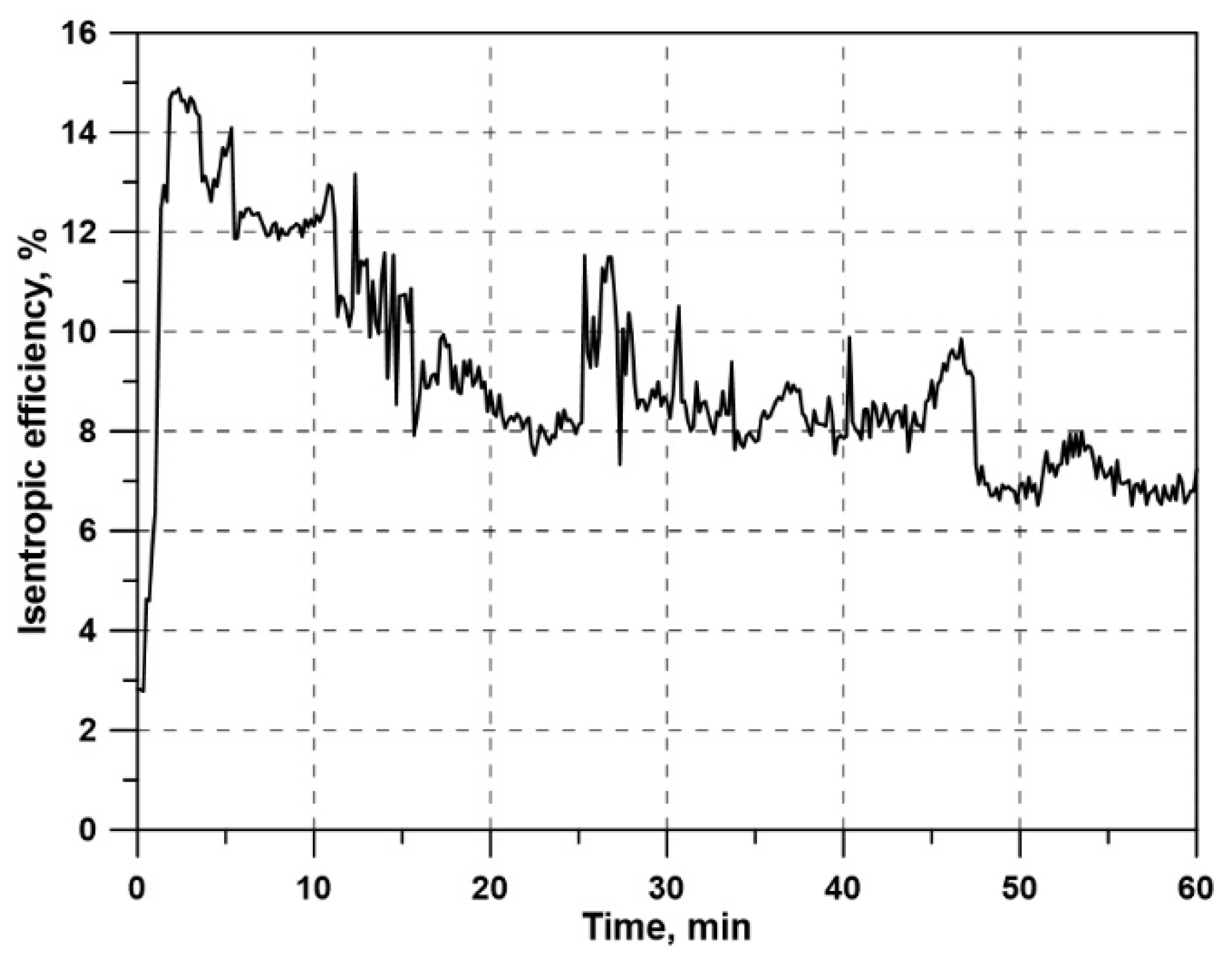
The calculated history of the expander isentropic efficiency is presented in Figure 22. The efficiency was calculated using the following equation:
Figure 22.
Calculated history of the expander isentropic efficiency.
The wet steam enthalpy () at the expander outlet was calculated by means of Equation (7). The steam quality at the expander outlet, which appears in this equation, was determined using Equation (5). In both cases, isentropic expansion was assumed.
The small difference between the inlet and outlet enthalpies (Figure 21) is partly associated with the operating principle of the Roots machine. Its theoretical internal volume ratio is close to unity, and therefore, only limited internal expansion occurs before the working chamber communicates with the outlet [22]. Consequently, part of the available pressure difference is lost during pressure equalisation rather than converted into useful shaft work. In addition, leakage, pressure losses, and non-optimal chamber filling and emptying may contribute to the low isentropic efficiency. Optimisation of port geometry and timing, or the introduction of a built-in volume ratio matched to the operating pressure ratio, could improve the performance of a Roots machine specifically designed for expander operation. The isentropic efficiency was approximately 11–15% during saturated-steam operation, compared with 7–10% during wet-steam operation. The observed decrease may partly reflect additional losses associated with the presence of the liquid phase.
This interpretation is qualitatively consistent with findings reported for other steam expansion devices. Grieb and Brümmer [42] showed that surface condensation in steam-driven twin-screw expanders can increase the admitted mass flow without a corresponding increase in power output, thereby reducing efficiency. Wetness-related losses have also been reported in the last stages of steam turbines, including thermodynamic losses associated with non-equilibrium condensation and mechanical losses associated with droplet motion and interaction with the blades [43].
Although the operating principles of these machines differ, vapour–droplet velocity differences and liquid interaction with the rotors and casing are likewise plausible sources of additional dissipation in a Roots expander. This analogy is qualitative and does not imply identical loss mechanisms or their relative importance [42,43]. Condensation and two-phase flow effects should therefore be considered possible contributors to the observed decrease in efficiency, as their individual contributions were not quantified in the present study.
The measured quantities, ranges, and measurement errors obtained at the test stand are listed in Table 5.
Table 5.
Measurement ranges and errors for selected quantities.
The total active power generated by the Linz Electric E1S13S A/4 generator was measured using a Klemsan EMD 4 power meter. The measurement range was 0–8 kW, with a declared uncertainty of ±1%. The instrument has an accuracy class of 0.5. Since the generator was connected to a purely resistive load consisting of electric heaters, the power factor was approximately equal to unity (cos φ ≈ 1).
Taking into account the measurement results and the data in Table 5, the uncertainty in the determination of selected quantities y was calculated in accordance with the uncertainty propagation rule. The following equation describes the rule:
where
and denote, respectively, the sensitivity coefficients and measurement accuracy.
Table 6 shows the uncertainties in the indirect measurements of steam quality and expander isentropic efficiency, calculated at the selected 50th minute of the measurement series (most variables have reached or are close to steady state).
Table 6.
Uncertainties in the indirect measurements of selected quantities.
The uncertainty values shown in Table 6 are small. This indicates that the measurement devices’ ranges are well selected and that the measurements were accurate.
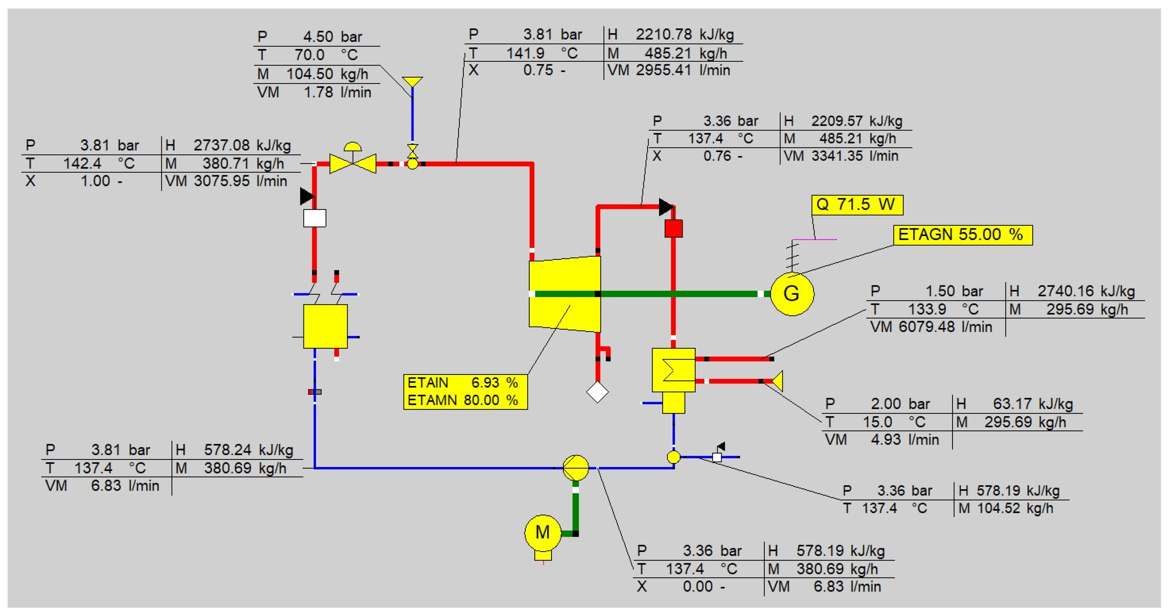
The correctness of the calculation results obtained from the experimental studies was confirmed by an additional simulation using the Ebsilon Professional software (Version 14.02). The boundary conditions used in the simulation with Ebsilon Professional software are listed in Table 7. The simulation was performed for the operating point corresponding to the 50th minute of the experiment. The measured parameters of saturated steam and injection water were assumed to be the boundary conditions. Subsequently, the wet-steam mixing process, expansion in the rotary blower and electricity generation were simulated under steady-state conditions. The resulting electrical power output was 71.5 W.
Table 7.
Quantities and their basic parameters used in the simulation process.
Additional assumptions were as follows:
- -
- Expander isentropic efficiency: ηis = 6.93%.
- -
- Mechanical efficiency of the Roots blower operating as an expander: ηm = 80%.
- -
- Generator efficiency: ηg = 55%.
The assumed value of expander mechanical efficiency (ηm = 0.8) is conservative compared with typical values reported for industrial Roots blowers, for which mechanical efficiencies above 90% are generally reported due to relatively low bearing and gear losses. However, in the present study, the machine operated under conditions for which it was not originally designed, i.e., as a wet-steam expander. Therefore, a lower mechanical efficiency was assumed to account for potential additional losses associated with this unconventional operating mode. To account for the effect of the mechanical efficiency uncertainty on the expander’s isentropic efficiency, this uncertainty was taken into account in the error propagation analysis—Equation (18). The standard uncertainty of the mechanical efficiency was calculated for the range of 0.80–0.85, assuming a rectangular distribution.
The simulation results are shown in Figure 23. The achieved electric power of approximately 71.5 W corresponds to the power measured at the generator terminals at the 50th minute of the measuring cycle (Figure 20). Consistency is also observed for the values of the other parameters, which confirms the accuracy of the calculations—Equations (1)–(9) and (15)–(17).
Figure 23.
Simulation results for the selected time instant of the experiment.
In addition, Table 8 shows the complete energy balance of the system for the operating point shown in Figure 23.
Table 8.
Complete energy balance of the system.
The actual net power output of the complete system was determined by accounting for the electricity consumption of all auxiliary equipment, namely the injection-water pump, the condensate circulation pump, and the cooling-water pump supplying the condenser. For the representative operating point shown in Figure 23, the generator produced 71.5 W of gross electrical power. The power consumption of the auxiliary equipment was estimated at approximately 4 W for the injection-water pump, 8 W for the condensate circulation pump, and 7 W for the cooling-water pump, resulting in a total auxiliary demand of approximately 19 W. Consequently, the actual net electrical power output of the complete installation was approximately 52.5 W. The thermal power supplied in the boiler at the same operating point was 228.3 kW. Therefore, the net thermal-to-electric efficiency of the overall system was approximately 0.023%. During the experiments, the wet-steam mass flow rate ranged from approximately 425 to 500 kg/h, while the measured generator output ranged from 70 to 130 W. These results indicate that the tested installation should be regarded primarily as a proof-of-concept demonstrator for electricity generation from wet steam using a rotary blower operating in reverse mode, rather than as an optimised power-generation system.
Furthermore, for comparison, Table 9 shows the values calculated during the preliminary design stage alongside those measured on the test stand.
Table 9.
Comparison of selected parameters during the preliminary design and measurement stages.
Table 9 compares the preliminary design assumptions with the parameters measured on the experimental test stand. The experimental steam quality values were generally consistent with the design assumptions. The measured isentropic efficiency of the expander (7–10%) was slightly higher than the conservative design estimate of 5%. However, the generated electrical power (70–130 W) was lower than the predicted value of 241 W. This discrepancy can be primarily attributed to the lower pressure ratio achieved during the experiments, the low rotational speed of the generator, mechanical losses in the belt transmission, and the operation of the generator far below its rated power, which resulted in reduced efficiency.
6. Summary
This paper presents an experimental investigation of a wet steam cycle (WSC) using a commercial Roots blower operated in reverse as an expander. Wet steam was produced by injecting water into saturated steam, and CFD calculations were used to determine the required mixing length downstream of the injection nozzle. A dedicated test stand was constructed and equipped with a data acquisition system.
Based on the experimental and numerical results, the main findings can be summarised as follows:
- The experimental results confirmed that a commercial Roots blower operated in reverse can generate electricity when supplied with wet steam. Stable operation was observed for an inlet gauge pressure of approximately 2–2.8 bar, a wet-steam mass flow rate of approximately 425–500 kg/h and a steam quality of approximately 0.70–0.83.
- The electrical power generated during wet-steam operation ranged from approximately 70 to 130 W, while the calculated isentropic efficiency of the expander was approximately 7–10%. These results confirm the feasibility of the concept, although the tested commercial blower was not designed or optimised for expander operation.
- The CFD analysis showed that, under the analysed conditions, the straight mixing section downstream of the water injection nozzle should not be shorter than 12D in order to achieve the adopted level of steam-water mixture homogeneity.
- The thermodynamic calculations and Ebsilon Professional simulations were consistent with the experimental results. For the selected operating point, the simulated electrical power of approximately 71.5 W agreed closely with the measured value.
The relatively low isentropic efficiency should be interpreted primarily in the context of the operating characteristics of the adapted Roots blower. Its performance may additionally be affected by leakage, pressure losses, relatively low rotational speed and two-phase-flow effects. Therefore, the tested machine should be regarded primarily as a demonstrator confirming the feasibility of wet-steam operation rather than as a final high-efficiency expander design.
The experiment covered only a small range of changes in the PR coefficient, the wet steam mass flow rate, and steam quality. Based on the results of the experimental testing, the following further studies are planned to verify the system’s universality and reliability:
- -
- increasing the range of steam quality;
- -
- increasing the mass flow rate of the wet steam driving the expander;
- -
- increasing the range of steam pressure at the expander inlet;
- -
- equipping the test stand with a torque measurement system;
- -
- increasing the generator rotational speed by changing the belt pulley diameters, which will make it possible to achieve higher values of power and isentropic efficiency;
- -
- improving the cooling of the expander body, with particular emphasis on the bearing zones (this will lead to the expander’s greater mechanical efficiency);
- -
- replacing the seals on the expander shaft to supply the device with wet steam at higher pressure and temperature;
- -
- using cooling oil suitable for high-temperature operation;
- -
- performing a comprehensive leakage analysis using CFD modelling.
Author Contributions
Conceptualization, W.Z. and A.C.; methodology, W.Z.; software, K.M.; validation, K.M. and J.C.; formal analysis, W.Z.; investigation, K.M., W.Z. and A.C.; resources, K.M.; data curation, K.M.; writing—original draft preparation, W.Z.; writing—review and editing, A.C.; visualization, J.C.; supervision, W.Z.; project administration, A.C.; funding acquisition, W.Z. All authors have read and agreed to the published version of the manuscript.
Funding
This research was funded in whole by the National Science Centre, Poland, grant number UMO-2022/47/B/ST8/02108.
Data Availability Statement
Data are available upon request.
Conflicts of Interest
The authors declare no conflict of interest.
Nomenclature
| c | specific heat, kJ/(kgK) |
| D | diameter, m |
| h | enthalpy, kJ/kg |
| mass flow rate, kg/h | |
| p | pressure, MPa |
| r | heat of vaporisation, kJ/kg |
| s | entropy, kJ/(kgK) |
| t | temperature, °C |
| x | steam quality |
| Greek symbols | |
| η | efficiency |
| Φ | power, W |
| Subscripts | |
| c | condensate |
| dr | drift |
| g | power generator |
| in | inlet |
| is | isentropic |
| k | phase k |
| l | liquid phase |
| m | mechanical |
| mix | mixture |
| s | saturated steam |
| w | injection water |
| 1 | inlet |
| 2 | outlet |
| Superscripts | |
| ′ | boiling water |
| ″ | saturated steam |
References
- Cheng, L.; Xia, G. Progress and Prospects for Research and Technology Development of Supercritical CO2 Thermal Conversion Systems for Power, Energy Storage, and Waste Heat Recovery. Heat Transf. Eng. 2024, 45, 1836–1853. [Google Scholar] [CrossRef] [Scilit]
- Bao, J.; Zhao, L. A review of working fluid and expander selections for organic Rankine cycle. Renew. Sustain. Energy Rev. 2013, 24, 325–342. [Google Scholar] [CrossRef] [Scilit]
- Sornek, K.; Jankowski, M.; Borsukiewicz, A.; Filipowicz, M. The Optimization of Steam Generation in a Biomass-Fired Micro-Cogeneration Prototype Operating on a Modified Rankine Cycle. Sustainability 2024, 16, 9. [Google Scholar] [CrossRef] [Scilit]
- He, N.; Chi, X.; Feng, C.; Lu, M.; Zhang, L.; Dong, J. Numerical Investigation on the Effect of Wet Steam and Ideal Gas Models for Steam Ejector Driven by Ship Waste Heat. Appl. Sci. 2023, 13, 12516. [Google Scholar] [CrossRef] [Scilit]
- Wang, C.; Wang, L.; Zhao, H.X.; Du, Z.; Ding, Z. Effects of superheated steam on non-equilibrium condensation in ejector primary nozzle. Int. J. Refrig. 2016, 67, 214–226. [Google Scholar] [CrossRef] [Scilit]
- Young, J.B. Spontaneous condensation of steam in supersonic nozzles. Physicochem. Hydrodyn. 1982, 3, 57–82. [Google Scholar]
- Young, J.B. Two-dimensional nonequilibrium wet-steam calculations for nozzles and turbine cascades. J. Turbomach. 1992, 114, 569–579. [Google Scholar] [CrossRef] [Scilit]
- Tian, Y.; Wang, Z.; Liu, Z.; Jiang, Z.; Zhao, Z.; Zhang, H. Two-phase flow characteristics and leakage in the shaft seal of steam screw expanders. Int. J. Refrig. 2025, 172, 214–227. [Google Scholar] [CrossRef] [Scilit]
- Weitzer, M.; Müller, D.; Karl, J. Two-phase expansion processes in heat pump—ORC systems (Carnot batteries) with volumetric machines for enhanced off-design efficiency. Renew. Energy 2022, 199, 720–732. [Google Scholar] [CrossRef] [Scilit]
- Imran, M.; Usman, M.; Park, B.S.; Lee, D.H. Volumetric expanders for low grade heat and waste heat recovery applications. Renew. Sustain. Energy Rev. 2016, 57, 1090–1109. [Google Scholar] [CrossRef] [Scilit]
- He, X.; Yu, Z.; Gu, Y.; Zhao, Z.; Zheng, L.; Lu, S. Modeling and Off-Design Performance Analysis of a Screw Expander-Based Steam Pressure Energy Recovery System in a Combined Heat and Power Unit. ACS Omega 2021, 6, 35442–35456. [Google Scholar] [CrossRef] [Scilit] [PubMed]
- Bianchi, G.; Marchionni, M.; Miller, J.; Tassou, S.A. Modelling and off-design performance optimisation of a trilateral flash cycle system using two-phase twin-screw expanders with variable built-in volume ratio. Appl. Therm. Eng. 2020, 179, 115671. [Google Scholar] [CrossRef] [Scilit]
- Iqbal, M.A.; Rana, S.; Ahmadi, M.; Date, A.; Akbarzadeh, A. Experimental study on the prospect of low-temperature heat to power generation using Trilateral Flash Cycle (TFC). Appl. Therm. Eng. 2020, 172, 115139. [Google Scholar] [CrossRef] [Scilit]
- Skiadopoulos, A.; Antonopoulou, C.; Atsonios, K.; Grammelis, P.; Gkountas, A.; Bakalis, P.; Manolakos, D. Assessment of the Trilateral Flash Cycle potential for efficient solar energy conversion in Europe. Energy Convers. Manag. X 2023, 20, 100432. [Google Scholar] [CrossRef] [Scilit]
- Ziviani, D.; Gusev, S.; Schuessler, S.; Achaichia, A.; Braun, J.E.; Groll, E.A.; De Paepe, M.; van den Broek, M. Employing a single-screw expander in an Organic Rankine Cycle with liquid flooded expansion and internal regeneration. Energy Procedia 2017, 129, 379–386. [Google Scholar] [CrossRef] [Scilit]
- Li, J.; Li, P.; Pei, G.; Alvi, J.Z.; Ji, J. Analysis of a novel solar electricity generation system using cascade Rankine cycle and steam screw expander. Appl. Energy 2016, 165, 627–638. [Google Scholar] [CrossRef] [Scilit]
- Iodice, P.; Langella, G.; Amoresano, A. Modeling and energetic-exergetic evaluation of a novel screw expander-based direct steam generation solar system. Appl. Therm. Eng. 2019, 155, 82–95. [Google Scholar] [CrossRef] [Scilit]
- Li, P.; Li, J.; Tan, R.; Wang, Y.; Pei, G.; Jiang, B.; Tang, J. Thermo-economic evaluation of an innovative direct steam generation solar power system using screw expanders in a tandem configuration. Appl. Therm. Eng. 2019, 148, 1007–1017. [Google Scholar] [CrossRef] [Scilit]
- Tian, Y.; Xing, Z.; He, Z.; Wu, H. Modeling and performance analysis of twin-screw steam expander under fluctuating operating conditions in steam pipeline pressure energy recovery applications. Energy 2017, 141, 692–701. [Google Scholar] [CrossRef] [Scilit]
- Nikolov, A.; Brümmer, A. Investigating a small oil-flooded twin-screw expander for waste heat utilisation in ORC systems. Energies 2017, 10, 869. [Google Scholar] [CrossRef] [Scilit]
- Dumont, O.; Parthoens, A.; Dickes, R.; Lemort, V. Experimental investigation and optimal performance assessment of four volumetric expanders (scroll, screw, piston and roots) tested in a small-scale organic Rankine cycle system. Energy 2018, 165, 1119–1127. [Google Scholar] [CrossRef] [Scilit]
- Parthoens, A.; Dumont, O.; Guillaume, L.; Lemort, V. Experimental and numerical investigation of a Roots expander integrated into an ORC power system. In Proceedings of the 24th International Compressor Engineering Conference at Purdue, West Lafayette, IN, USA, 9–12 July 2018. [Google Scholar]
- Singh, G.; Sun, S.; Kovacevic, A.; Li, Q.; Bruecker, C. Transient flow analysis in a Roots blower: Experimental and numerical investigations. Mech. Syst. Signal Process. 2019, 134, 106305. [Google Scholar] [CrossRef] [Scilit]
- Casari, N.; Fadiga, E.; Pinelli, M.; Suman, A.; Kovacevic, A.; Rane, S.; Ziviani, D. Numerical investigation of oil injection in a Roots blower operated as expander. IOP Conf. Ser. Mater. Sci. Eng. 2019, 604, 012075. [Google Scholar] [CrossRef] [Scilit]
- Zima, W.; Cebula, A.; Morański, K.; Cisek, J. Concept of a test stand for electricity generation from waste heat using wet steam. Arch. Thermodyn. 2025, 46, 49–56. [Google Scholar] [CrossRef] [Scilit]
- Xu, Z.Y.; Wang, R.Z.; Yang, C. Perspectives for low-temperature waste heat recovery. Energy 2019, 176, 1037–1043. [Google Scholar] [CrossRef] [Scilit]
- Nandaliarasyad, N.; Prelifezia, N.P.; Wulandari, D.A.; Purnomo, C.A.; Aji, A.B.K. Study of Development Scenarios for Bottoming Unit Binary Cycle to Utilize Exhaust Steam from Back Pressure Turbine Geothermal Power Plant. IOP Conf. Ser. Earth Environ. Sci. 2020, 417, 012017. [Google Scholar] [CrossRef] [Scilit]
- Wołowicz, M.; Kolasiński, P.; Badyda, K. Modern Small and Microcogeneration Systems—A Review. Energies 2021, 14, 785. [Google Scholar] [CrossRef] [Scilit]
- Heliex Power Technology. Twin Screw Turbine. Available online: https://heliexpower.com/technology/ (accessed on 24 April 2024).
- Kolasiński, P.; Błasiak, P.; Rak, J. Experimental and Numerical Analyses on the Rotary Vane Expander Operating Conditions in a Micro Organic Rankine Cycle System. Energies 2016, 9, 606. [Google Scholar] [CrossRef] [Scilit]
- Kolasiński, P. Application of the Multi-Vane Expanders in ORC Systems—A Review on the Experimental and Modeling Research Activities. Energies 2019, 12, 2975. [Google Scholar] [CrossRef] [Scilit]
- Daniarta, S.; Kolasiński, P.; Imre, A.R. Thermodynamic efficiency of trilateral flash cycle, organic Rankine cycle and partially evaporated organic Rankine cycle. Energy Convers. Manag. 2021, 249, 114731. [Google Scholar] [CrossRef] [Scilit]
- Van Heule, X.; Couvreur, K.; De Paepe, M.; Beyne, W.; Lecompte, S. Sensitivity study of a partially evaporating organic Rankine cycle model with non-equilibrium expansion. Appl. Therm. Eng. 2025, 276, 126682. [Google Scholar] [CrossRef] [Scilit]
- Bellos, E. A detailed analysis of waste heat recovery organic Rankine cycle with partial evaporation and different working fluids. Appl. Therm. Eng. 2025, 263, 125410. [Google Scholar] [CrossRef] [Scilit]
- Dawo, F.; Buhr, J.; Schifflechner, C.; Wieland, C.; Spliethoff, H. Experimental assessment of an Organic Rankine Cycle with a partially evaporated working fluid. Appl. Therm. Eng. 2023, 221, 119858. [Google Scholar] [CrossRef] [Scilit]
- Report Spring 2011; Manufacturer’s Material (Available on Request). Available online: www.kaeser.com.
- Hsieh, J.-C.; Tsai, H.-T.; Chen, Y.-T.; Chen, C.-L.; Lin, C.-F. Volumetric and Turbine Expander Technologies in Organic Rankine Cycle Systems: A Systematic Review. Green Energy Fuel Res. 2025, 2, 197–217. [Google Scholar] [CrossRef] [Scilit]
- STEAG Energy Services GmbH. Ebsilon Professional, version 14.02—Release (Patch 2). 2019.
- ANSYS Inc. ANSYS Fluent Theory Guide, release/version 2025 R1; ANSYS Inc: Canonsburg, PA, USA, 2025. [Google Scholar]
- Rotary Blowers (Single Block): OMEGA Series. Available online: https://www.kaeser.com/int-en/products/blowers/rotary-lobe-blowers-single-block (accessed on 24 March 2026).
- Linz Electric. Technical Data Sheet. Alternator E1S13S A/4. Available online: https://www.linzelectric.com/uploads/ProdottiArticoli/04-E1S13S_A-41.pdf (accessed on 10 February 2026).
- Grieb, M.; Brümmer, A. Investigation into the effects of surface condensation in steam-driven twin screw expanders. IOP Conf. Ser. Mater. Sci. Eng. 2019, 604, 012044. [Google Scholar] [CrossRef] [Scilit]
- Fan, S.; Wang, Y.; Yao, K.; Shi, J.; Han, J.; Wan, J. Distribution Characteristics of High Wetness Loss Area in the Last Two Stages of Steam Turbine under Varying Conditions. Energies 2022, 15, 2527. [Google Scholar] [CrossRef] [Scilit]



Disclaimer/Publisher’s Note: The statements, opinions and data contained in all publications are solely those of the individual author(s) and contributor(s) and not of MDPI and/or the editor(s). MDPI and/or the editor(s) disclaim responsibility for any injury to people or property resulting from any ideas, methods, instructions or products referred to in the content. |
© 2026 by the authors. Licensee MDPI, Basel, Switzerland. This article is an open access article distributed under the terms and conditions of the Creative Commons Attribution (CC BY) license.